WO2019039248A1 - パイロット式制御弁 - Google Patents
パイロット式制御弁 Download PDFInfo
- Publication number
- WO2019039248A1 WO2019039248A1 PCT/JP2018/029360 JP2018029360W WO2019039248A1 WO 2019039248 A1 WO2019039248 A1 WO 2019039248A1 JP 2018029360 W JP2018029360 W JP 2018029360W WO 2019039248 A1 WO2019039248 A1 WO 2019039248A1
- Authority
- WO
- WIPO (PCT)
- Prior art keywords
- valve body
- pilot
- main valve
- main
- outlet
- Prior art date
- Legal status (The legal status is an assumption and is not a legal conclusion. Google has not performed a legal analysis and makes no representation as to the accuracy of the status listed.)
- Ceased
Links
Images


Classifications
-
- F—MECHANICAL ENGINEERING; LIGHTING; HEATING; WEAPONS; BLASTING
- F16—ENGINEERING ELEMENTS AND UNITS; GENERAL MEASURES FOR PRODUCING AND MAINTAINING EFFECTIVE FUNCTIONING OF MACHINES OR INSTALLATIONS; THERMAL INSULATION IN GENERAL
- F16K—VALVES; TAPS; COCKS; ACTUATING-FLOATS; DEVICES FOR VENTING OR AERATING
- F16K31/00—Actuating devices; Operating means; Releasing devices
- F16K31/02—Actuating devices; Operating means; Releasing devices electric; magnetic
- F16K31/06—Actuating devices; Operating means; Releasing devices electric; magnetic using a magnet, e.g. diaphragm valves, cutting off by means of a liquid
-
- F—MECHANICAL ENGINEERING; LIGHTING; HEATING; WEAPONS; BLASTING
- F16—ENGINEERING ELEMENTS AND UNITS; GENERAL MEASURES FOR PRODUCING AND MAINTAINING EFFECTIVE FUNCTIONING OF MACHINES OR INSTALLATIONS; THERMAL INSULATION IN GENERAL
- F16K—VALVES; TAPS; COCKS; ACTUATING-FLOATS; DEVICES FOR VENTING OR AERATING
- F16K31/00—Actuating devices; Operating means; Releasing devices
- F16K31/12—Actuating devices; Operating means; Releasing devices actuated by fluid
- F16K31/36—Actuating devices; Operating means; Releasing devices actuated by fluid in which fluid from the circuit is constantly supplied to the fluid motor
- F16K31/40—Actuating devices; Operating means; Releasing devices actuated by fluid in which fluid from the circuit is constantly supplied to the fluid motor with electrically-actuated member in the discharge of the motor
Definitions
- the present invention relates to a pilot type control valve suitable for use in a heat pump type cooling and heating system or the like, and in particular, lifts and drives a pilot valve body and responds to the pilot valve body to respond to the pilot valve body.
- the present invention relates to a pilot control valve adapted to be opened and closed by the body.
- pilot type solenoid valve in which a pilot valve body is driven by an electromagnetic actuator (solenoid) and the large-diameter main valve port is opened and closed by the main valve body in response to the pilot valve body
- the main valve body is provided with a pilot passage for releasing the pressure of the back pressure chamber to the outlet, and the pilot passage is opened and closed by the pilot valve body driven to move up and down by the electromagnetic actuator.
- a metal pilot valve body having a seal member attached to the tip thereof is usually press-fitted to a plunger driven up and down by an electromagnetic actuator. It is connected and fixed by caulking or the like, and a compression coil spring as a biasing member is compressed between the plunger and the suction element to bias the plunger (and the pilot valve body) away from the suction element.
- the present invention has been made in view of the above circumstances, and an object of the present invention is to provide a pilot type control valve which contributes to weight reduction and can reduce the number of assembling steps and improve the assemblability.
- the purpose is to
- a pilot control valve basically comprises a valve body provided with an inlet and an outlet, a main valve body for opening and closing the outlet, and the main valve body.
- a storage chamber in which a valve body is disposed and divided into a main valve chamber and a back pressure chamber by the main valve body, and the pressure of the main valve chamber or the inlet are supplied to the back pressure chamber.
- the main valve body is provided with a pilot passage for releasing the pressure of the back pressure chamber to the outlet, and the pilot passage is opened and closed by a pilot valve body driven up and down by an electromagnetic actuator.
- the outlet is opened and closed by the main valve body, and biasing is performed between a receiving portion provided on the pilot valve body and a suction element of the electromagnetic actuator.
- a member is interposed between the biasing member The force, the pilot valve body is pressed against the plunger of the electromagnetic actuator, the plunger is characterized by being urged away from said suction element.
- the receiving portion is provided integrally or separately from the pilot valve body.
- the receiving portion is mounted in an outer peripheral groove provided in the pilot valve body.
- the receiving portion is disposed in an insertion hole provided in the plunger.
- a stopper mechanism is provided between the pilot valve body and the suction element to determine the movement limit of the pilot valve body by the biasing force of the biasing member.
- the pilot valve body is preferably made of resin.
- the receptacle is preferably made of a magnetic material.
- the pilot control valve basically comprises a valve body provided with an inlet and an outlet, a main valve body for opening and closing the outlet, and the main valve body. And a storage chamber divided into a main valve chamber and a back pressure chamber by the main valve body, and a pressure supply passage for supplying the pressure of the main valve chamber or the inlet to the back pressure chamber.
- the main valve body is provided with a pilot passage for releasing the pressure of the back pressure chamber to the outflow port, and the pilot passage is opened and closed by a pilot valve member which is moved up and down by a lifting drive device.
- the outlet is opened and closed by the main valve body, and a biasing member is interposed between the receiving portion provided on the pilot valve body and the valve body or the elevation drive device.
- the biasing force of the biasing member It is a pilot control valve, characterized in that the valve body is adapted to be pressed against the valve body to the lifting drive.
- the biasing member is interposed between the receiving portion provided on the pilot valve body and the suction element, and the pilot valve body is pressed against the plunger by the biasing force of the biasing member, and the plunger is Since the pilot valve body is not required to be connected and fixed to the plunger by press-fitting, caulking or the like because it is biased in the direction away from the suction element, the strength (stiffness) of the pilot valve body itself can be suppressed low, and weight increase can be avoided. . In addition, since the suction force required for the operation of the plunger and the pilot valve can be reduced, weight reduction can be achieved also by this. Furthermore, since the process of connecting and fixing the pilot valve body to the plunger is not necessary, the number of assembling steps can be reduced, and the assembling process can be simplified to improve the assemblability.
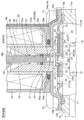
- FIG. 2 is a perspective view of the housing shown in FIG. 1; It is a principal part enlarged longitudinal cross-sectional view provided to operation
- FIG. 1 shows the state (a pilot valve body: open, main valve body closed). It is a principal part enlarged longitudinal cross-sectional view by which it uses for operation description of the pilot type solenoid valve shown by FIG. 1, and is a figure which shows valve-opened state (pilot valve body: open, main valve body: open).
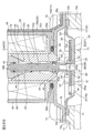
- FIG. 1 is a longitudinal sectional view showing an embodiment of a pilot-type solenoid valve as a pilot-type control valve according to the present invention.
- FIG. 1 is a cross-sectional view along the plane in which the left side of the O line passes through the center of the connector portion 56 toward the paper surface, and the right side of the O line is a cross-sectional view of the vertical surface toward the paper surface.
- the gap formed between the members, the separation distance between the members, and the like are large in comparison with the dimensions of the respective constituent members in order to facilitate understanding of the invention and for convenience in drawing. Or it may be drawn small.
- the pilot type solenoid valve 1 of the illustrated embodiment is used, for example, in a heat pump type cooling and heating system such as a car air conditioner, and mainly includes a bottomed short cylindrical valve body 10 having an inlet 11 and an outlet 12; An electromagnetic actuator (lifting and lowering drive device) 50 provided on the upper side of the valve main body 10 is provided.
- a heat pump type cooling and heating system such as a car air conditioner
- a cylindrical portion 13 provided with an outlet 12 with a main valve seat 12a is formed (in the illustrated example, integrally formed), and orthogonal to the outlet 12;
- a lateral hole-like inlet 11 is provided on the side thereof.
- a lid member 14 made of a substantially dome-shaped magnetic metal (for example, iron or the like) is attached to the upper portion of the valve main body 10 so as to close the top opening of the valve main body 10.
- the lower end of the suction element 53 of the electromagnetic actuator 50 described later is internally fitted in substantially the center of the ceiling portion 14a of the lid member 14 and the pilot valve body 40 (the lower large diameter portion 43 thereof) is inserted.
- a hole 14c is provided.
- a flange portion 14b extends (downwardly) on the outer peripheral portion of the ceiling portion 14a, and the lid member 14 is fixed to (the upper portion of) the valve main body 10 via the flange portion 14b.
- the lid member 14 has the flange portions 14 b of the lid member 14 fastened and fixed to a plurality of mounting portions 10 a integrally provided on the outer periphery of the valve main body 10 and substantially symmetrical with respect to the axis O. As a result, the valve body 10 is assembled.
- a main valve body (also referred to as a diaphragm valve body) 20 having a diaphragm 21 is accommodated in the valve body 10, specifically, in a storage chamber 16 defined by the valve body 10 and the lid member 14 so as to be elastically deformable.
- the storage chamber 16 is partitioned by the main valve body 20 into a main valve chamber 17 and a back pressure chamber 18.
- a pilot passage (a pilot valve port) 39 with a pilot valve seat 39a for escaping the pressure of the back pressure chamber 18 to the outlet 12 penetrates in the vertical direction (direction of the axis O) at the central portion of the main valve body 20.
- the pilot passage 39 is opened and closed by a pilot valve body portion 40a of a pilot valve body 40 described later.
- a pressure supply passage for equalizing pressure from the main valve chamber 17 or the inlet 11 to the back pressure chamber 18 at a position separated from the central portion of the main valve body 20 (a position outside the A pressure passage) 19 is also provided.
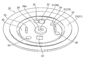
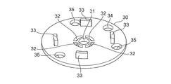
- the main valve body 20 is reinforced with a diaphragm 21 made of, for example, an elastic member such as rubber or Teflon (registered trademark), and a disc-like stopper 33 made of, for example, hard resin or metal. It is comprised with the member 30, and they are integrally formed by insert molding etc., for example.
- the diaphragm 21 and the reinforcing member 30 are integrated by insert molding, but it is sufficient if the diaphragm 21 and the reinforcing member 30 are fixed.
- the diaphragm 21 may be partially formed on the reinforcing member 30. A part of or may be fitted or fixed with an adhesive.
- the reinforcing member 30 is formed to have a larger diameter than the outlet 12, and the central portion of the pilot passage 39 (the central portion of the pilot passage 39 (see FIGS. 2A and 2B together with FIG. 1). And a through hole 32 for passing an elastic member constituting the diaphragm 21 when the main valve body 20 is formed.
- four through holes 32 having a generally fan-shaped planar view are provided at substantially equal angular intervals around the center hole 31 in the reinforcing member 30.
- a stopper 33 is provided so as to protrude.
- the stopper 33 prevents the pilot valve seat 39a provided on (the diaphragm 21 of) the main valve body 20 from colliding with the pilot valve body 40 or the like when the valve is opened (that is, when the main valve body 20 is lifted).
- the height is set higher than the height of the upper seal portion 24 of the diaphragm 21 described later.
- four substantially rectangular stoppers 33 are provided outside the through holes 32 of the reinforcing member 30 at substantially equal angular intervals.
- the stopper 33 is integrally formed with the reinforcing member 30, it may be formed separately (in other words, as a separate part) from the reinforcing member 30.
- the stopper may be formed on, for example, the diaphragm 21 or the ceiling portion 14 a of the lid member 14 or the like.
- the upper communication hole (pressure equalizing hole) constituting the pressure supply passage 19 (upper half)
- the diaphragm 21 basically has a relatively thick disk-like lower seal portion 22 formed on the lower surface side of the reinforcing member 30, and the outer periphery of the lower seal portion 22 (that is, the diaphragm A relatively thin elastically deforming portion 23 extended to the periphery of the inner wall 21), an annular upper seal portion 24 formed around the center hole 31 on the upper surface side of the reinforcing member 30 and on the through hole 32; A connecting portion (four connecting portions in this example) 25 formed in the through hole 32 of the reinforcing member 30 and connecting the lower seal portion 22 and the upper seal portion 24 is formed.
- a central hole 26 constituting (the lower part of) the pilot passage 39 is provided in the central portion of the lower seal portion 22, and the inner periphery of the upper seal portion 24 and the central hole 31 of the reinforcing member 30 and the lower portion are formed.
- the pilot passage 39 is formed by the central hole 26 of the side seal portion 22.
- a lower communication hole (also referred to as a pressure equalizing hole) 27 constituting a pressure supply passage 19 (lower half) is provided in the vicinity of the outer periphery of the lower seal portion 22.
- the pressure supply passage 19 is formed by the lower communication hole 27 and the upper communication hole 34 of the reinforcing member 30.
- the upper communication hole 34 of the reinforcement member 30 is slightly smaller than the lower communication hole 27 of the lower seal portion 22, and the passage diameter of the pilot passage 39 (the inner diameter of the upper seal portion 24, the reinforcement member 30
- the hole diameter of the central hole 31 and the hole diameter of the central hole 26 of the lower seal portion 22 are determined from the (minimum) passage diameter of the pressure supply passage 19 (here, the hole diameter of the upper communication hole 34 of the reinforcing member 30) It is slightly larger.
- the lower surface of the lower seal portion 22 of the diaphragm 21 constituting the main valve body 20 (in the illustrated example, an annular portion slightly inward of the lower communication hole 27 and slightly outward of the connecting portion 25)
- the main valve body 20a opens and closes the outlet 12 by contacting and separating the outlet 12 (the upper main valve seat 12a), and the upper surface of the upper seal 24 (in the illustrated example, from the outer edge of the upper seal 24)
- a pilot valve seat 39 a which contacts and separates the pilot valve body 40 (the pilot valve body portion 40 a at the lower end thereof) connected to the plunger 58 of the electromagnetic actuator 50. It is assumed.
- a diaphragm receiving portion 10 b is provided at the upper end of the valve body 10, and (the diaphragm 21 of the main valve body 20 is disposed to cover the top opening of the valve body 10).
- An outer peripheral portion (more specifically, a thick portion formed on the outer periphery of the elastically deformable portion 23) of (the elastically deformable portion 23) has a diaphragm receiving portion 10b and a lid member 14 provided on the upper end of the valve main body 10.
- the back pressure chamber 18 is formed on the upper side of the main valve body 20 in the storage chamber 16 by being pinched and held by the flange portion 14 b provided on the outer peripheral portion of the main valve body. 17 are formed.
- the pressure chamber 18 is in communication, and therefore the pilot passage 39 is closed by the pilot valve body 40 a of the pilot valve body 40, the inlet 11, the main valve chamber 17, and the back pressure chamber 18 are , High pressure fluid will be filled.
- the pressure supply passage 19 for supplying the pressure of the main valve chamber 17 to the inlet 11 to the back pressure chamber 18 is provided in the main valve body 20, but the pressure supply passage 19 Of course, it may be provided in the valve body 10 etc. other than the valve body 20.
- the diaphragm 21 and the reinforcing member 30 as described above are integrally formed, for example, by insert molding, whereby the rigidity of the diaphragm 21 by the reinforcing member 30 (especially, the main valve body portion 20a of the lower seal portion 22 or the upper side The strength of the pilot valve seat 39a at the seal portion 24 is maintained.
- An electromagnetic actuator (solenoid) 50 is mounted on and fixed to the upper portion of the valve body 10.
- the electromagnetic actuator 50 includes a resin coil bobbin 52 around which a solenoid coil 51 is wound.
- the coil bobbin 52 has a cylindrical tubular body 52a on which the solenoid coil 51 is encased, and a pair of flanges for regulating the variation of the solenoid coil 51 at the upper end and the lower end of the tubular body 52a. (The upper flange 52b and the lower flange 52c) are integrally formed.
- a cylindrical plunger 58 made of magnetic metal and a suction element 53 are disposed to face each other in the vertical direction on the inner periphery of (the cylindrical body 52a of the coil bobbin 52), and (the outer periphery of) the plunger 58
- the magnetic pole 59 made of a cylindrical body made of metal is covered.
- the cylindrical suction element 53 is disposed on the lower inner periphery of (the cylindrical body 52a of the coil bobbin 52), and the lower part of the suction element 53 is the lower end (opening) of the coil bobbin 52 (the cylindrical body 52a) It protrudes inside and is fixed to the fitting hole 14c of the lid member 14 by press fitting, caulking or the like.
- a stepped insertion hole (upper small diameter insertion hole 53a and lower large diameter insertion hole 53b) for inserting the lower portion of the pilot valve body 40 is provided in the suction element 53 along the vertical direction (the direction of the axis O). ing.
- the plunger 58 is disposed movably in the vertical direction (direction of the axis O) (on the both sides of the magnetic pole 59) on the inner peripheral upper portion of (the cylindrical body 52a of the coil bobbin 52).
- the cylindrical magnetic pole 59 is internally fitted on the inner peripheral upper portion of (the cylindrical body 52a of the coil bobbin 52), and the plunger 58 is inserted inside the magnetic pole 59 movably along the axis O direction. ing.
- the hollow portion formed inside the coil bobbin 52 (the cylindrical body portion 52a of the coil bobbin 52 (in the coil device 49 in which the solenoid coil 51 is wound around the coil bobbin 52))
- the wall surface facing the hollow portion is used as the inner wall surface of the plunger chamber 60.
- the plunger 58 is provided with a stepped insertion hole (upper small diameter insertion hole 58a and lower large diameter insertion hole 58b) for inserting the upper portion of the pilot valve body 40 along the vertical direction (direction of the axis O). There is.
- the magnetic pole 59 has a flange portion 59a protruding from the upper end thereof (outwardly) held between the upper surface of the coil bobbin 52 and the lower surface of (the ceiling portion 55a of the housing 55 described later) It is fixedly arranged between the plunger 58 and the plunger 58.
- a resin mold cover 54 is disposed to cover the coil bobbin 52 (and the solenoid coil 51 mounted on the coil bobbin 52), and the solenoid coil 51, the coil bobbin 52, and the suction element 53 are disposed outside the mold cover 54.
- the plunger 58 and the like are covered by a substantially gate-shaped housing 55.
- the housing 55 is made of a magnetic material (for example, iron or the like) in which a yoke surrounding the outer periphery of the coil device 49 including the solenoid coil 51, the coil bobbin 52, and the mold cover 54 is integrated.
- the housing 55 has a rectangular flat ceiling 55a covering the upper portion of the mold cover 54 so as to close the ceiling of the plunger chamber 60, as can be seen well with reference to FIG. 3 and FIG.
- a side leg 55b which extends downward from both sides of the portion 55a and covers the side (both sides) of the mold cover 54, and a valve is provided via a mounting leg 55c provided at the lower end of the side leg 55b. It is fixed to (the upper part of) the main body 10.
- the housing 55 holds the flange portion 14b of the lid member 14 between the attachment leg 55c of the housing 55 and the upper portion of the valve main body 10 (in other words, the flange portion of the lid member 14)
- the mounting leg 55c of the housing 55 is fastened and fixed to the mounting portion 10a of the valve main body 10 with bolts 15 while pinching 14b, so that the cover member 14 (flange portion 14b) and the cover member 14 (
- the valve body 10 is assembled in a state of being (magnetically) connected to the flange portion 14 b) of the valve body 10.
- a connector portion 56 is integrally formed on (the upper end side portion of) the mold cover 54, and an external terminal 57 for energizing the solenoid coil 51 is provided in a projecting manner inside the connector portion 56.
- the plunger 58 disposed in the plunger chamber 60 is connected to a stepped shaft-like pilot valve body 40 that opens and closes the pilot passage 39 of the main valve body 20 according to the energized state of the solenoid coil 51.
- the pilot valve body 40 may be made of resin or metal, for example, but resin is preferable because it is lightweight.
- the pilot valve body 40 is inserted from the upper side into the upper small diameter portion 41 inserted into the upper small diameter insertion hole 58a of the plunger 58, and the upper end is inserted into the lower large diameter insertion hole 58b of the plunger 58
- An intermediate body portion 42 inserted into the small diameter insertion hole 53a, and a lower large diameter portion 43 inserted into the lower large diameter insertion hole 53b of the suction element 53 are provided.
- the outer diameter of the lower large diameter portion 43 is slightly larger than the passage diameter of the pilot passage 39 of the main valve body 20, and slightly smaller than the outer diameter of the upper seal portion 24 of the diaphragm 21 constituting the main valve body 20. It is set to.
- An annular outer peripheral groove 44 is provided on the upper outer periphery (a portion inserted into the lower large diameter insertion hole 58b of the plunger 58) of the intermediate body portion 42 of the pilot valve body 40, and a semicircular washer, for example, The ring-shaped spring receptacle (receiving part) 45 of the structure which put two pieces together is engage
- a spring insertion groove 53c is formed on the inner peripheral surface of (the upper small diameter insertion hole 53a of) the suction element 53 with one end (lower end) closed and the other end (upper end) opened.
- the pilot valve body 40 is always upward (between the upper step surface (lower spring receiving surface) of the spring insertion groove 53 c and the lower surface (upper spring receiving surface) of the spring receiver 45 provided on the pilot valve body 40.
- a compression coil spring (biasing member) 46 which is biased in the valve opening direction) is contracted (so as to be externally inserted into the intermediate body portion 42 of the pilot valve body 40).
- the compression coil spring 46 (the outer peripheral step formed between the upper small diameter portion 41 and the middle body portion 42) of the pilot valve body 40 is inserted into the upper small diameter insertion hole 58a of the plunger 58 and the lower large diameter
- the plunger 58 is pressed against an inner circumferential step formed between the hole 58 b and connected with the plunger 58, and the plunger 58 is biased in a direction away from the suction element 53 (upward).
- a stopper that restricts upward movement of the pilot valve body 40 due to the biasing force of the compression coil spring 46 by the outer circumferential step formed between the radial portion 43 and the stopper (in other words, the upward movement limit of the pilot valve body 40 is defined)
- this stopper mechanism is not limited to the above configuration.
- the spring receiver 45 provided on the pilot valve body 40 may be made of metal or resin, for example, the suction force of the pilot valve body 40 toward the suction element 53 is enhanced by making it of magnetic material, for example. be able to.
- the spring receiving portion (receiving portion) 45 is formed separately (as a separate part) from the pilot valve body 40, it is of course possible to be integrally formed with the pilot valve body 40. It is. For example, a step in the radial direction may be provided on the surface of the intermediate body portion 42 of the pilot valve body 40, and this step may be used as a spring receiving portion (receiving portion).
- the lower portion of the lower large diameter portion 43 of the pilot valve body 40 is formed in a cylindrical shape, and a tapered surface (also referred to as a chamfered portion) 43b formed of a frusto-conical surface at the lower inner periphery of the cylindrical portion 43a.
- the tip end (outer end) portion of the tapered surface 43b contacts and separates from the pilot valve seat 39a formed on the main valve body 20 (upper seal portion 24 of the diaphragm 21) to open and close the pilot passage 39 Pilot valve body 40a.
- the outlet 12 of the valve body 10, the main valve body 20 (the pilot passage 39), the coil bobbin 52 (the tubular body 52a of the coil bobbin 52), the suction element 53, the plunger 58, the magnetic pole 59, and the pilot valve body 40 are arranged on the same axis O.
- the solenoid coil 51 when the solenoid coil 51 is energized (the suction coil 53, the plunger 58, the housing 55, the cover member 14, etc., the inner peripheral side of the solenoid coil 51, A magnetic path is formed on the outer peripheral side)
- the magnetic attraction generated by the solenoid coil 51 excites the attractor 53 and the plunger 58, and as shown in FIG. 4A, the plunger 58 resists the biasing force of the compression coil spring 46.
- the suction valve 53 sucks and moves downward, and the pilot valve body 40 is depressed accordingly, and the pilot valve body portion 40 a of the pilot valve body 40 is provided on the main valve body 20.
- the pilot passage 39 is closed by being pressed (seated) on the seat 39a.
- the pilot valve body 40 presses the main valve body 20 downward (in the valve closing direction) (against the elastic force (pushing-up force) of the diaphragm 21 of the main valve body 20), so the outlet 12 is also closed. .
- the high pressure fluid introduced from the inlet 11 to the main valve chamber 17 is not discharged to the outlet 12, but the high pressure fluid is back pressure through the pressure supply passage 19 provided in the main valve body 20. Since it is introduced into the chamber 18, the back pressure chamber 18 also has a high pressure, and the main valve body 20 a of the main valve body 20 is strongly pressed against the main valve seat 12 a of the outlet 12.
- the fluid (pressure) in the back pressure chamber 18 is drawn out (relieved) to the outlet 12 through the pilot passage 39, the pressure in the back pressure chamber 18 decreases, and the inlet 11 and the main valve chamber 17 (high pressure) Force that pushes up the main valve body 20 due to the differential pressure generated between the valve and the back pressure chamber 18 (low pressure) and the force that pushes up the main valve body 20 by the elastic force of the diaphragm 21 of the main valve body 20
- the main valve body 20 is pushed up (until the stopper 33 abuts on the ceiling portion of the storage chamber 16 (that is, the ceiling portion 14a of the lid member 14)) as shown in FIG. 4C.
- the outlet 12 is open.
- the compression coil spring (biasing member) 46 is interposed between the spring receiver (receiver) 45 provided on the pilot valve body 40 and the suction member 53. Because the pilot valve body 40 is pressed against the plunger 58 by the biasing force of the compression coil spring 46 and the plunger 58 is biased in the direction away from the suction bar 53, the pilot valve body 40 is Since it is not necessary to connect and fix them, and the strength (stiffness) of the pilot valve body 40 itself can be reduced, weight increase can be avoided. Further, since the suction force required for the operation of the plunger 58 and the pilot valve body 40 can be reduced, weight reduction can also be achieved by this. Furthermore, since the process of connecting and fixing the pilot valve body 40 to the plunger 58 is not necessary, the number of assembling steps can be reduced, and the assembling process can be simplified to improve the assemblability.
- the main valve body (diaphragm valve body) 20 having the diaphragm 21 is adopted, but as the main valve body 20, a main valve body of another type (for example, a piston type etc.) can be applied There is no need to elaborate.
- the electromagnetic actuator (solenoid) 50 utilizing an electromagnetic force is adopted as the elevation drive device for raising and lowering the pilot valve body 40, but instead of the plunger 58, an electric actuator as the elevation drive device
- the pilot valve body 40a provided at the lower end of the valve shaft while inserting the upper end portion of the valve shaft (member provided with the pilot valve body 40) into this member using a member that is raised and lowered by the electric motor (stepping motor) You may employ
- a compression coil spring 46 as a biasing member be disposed between the valve body (or the lift drive fixed to the valve body) and a spring receiver provided on the valve shaft.
Landscapes
- Engineering & Computer Science (AREA)
- General Engineering & Computer Science (AREA)
- Mechanical Engineering (AREA)
- Magnetically Actuated Valves (AREA)
- Fluid-Driven Valves (AREA)
Applications Claiming Priority (2)
| Application Number | Priority Date | Filing Date | Title |
|---|---|---|---|
| JP2017162460A JP6879556B2 (ja) | 2017-08-25 | 2017-08-25 | パイロット式制御弁 |
| JP2017-162460 | 2017-08-25 |
Publications (1)
| Publication Number | Publication Date |
|---|---|
| WO2019039248A1 true WO2019039248A1 (ja) | 2019-02-28 |
Family
ID=65438674
Family Applications (1)
| Application Number | Title | Priority Date | Filing Date |
|---|---|---|---|
| PCT/JP2018/029360 Ceased WO2019039248A1 (ja) | 2017-08-25 | 2018-08-06 | パイロット式制御弁 |
Country Status (2)
| Country | Link |
|---|---|
| JP (1) | JP6879556B2 (enExample) |
| WO (1) | WO2019039248A1 (enExample) |
Cited By (1)
| Publication number | Priority date | Publication date | Assignee | Title |
|---|---|---|---|---|
| CN117108811A (zh) * | 2023-10-10 | 2023-11-24 | 郑翰林 | 一种先导阀 |
Families Citing this family (1)
| Publication number | Priority date | Publication date | Assignee | Title |
|---|---|---|---|---|
| JP7557669B2 (ja) | 2021-02-16 | 2024-09-30 | パナソニックIpマネジメント株式会社 | 給水電磁弁 |
Citations (3)
| Publication number | Priority date | Publication date | Assignee | Title |
|---|---|---|---|---|
| JP2011169404A (ja) * | 2010-02-18 | 2011-09-01 | Rinnai Corp | 電磁弁 |
| WO2016041650A1 (en) * | 2014-09-19 | 2016-03-24 | Danfoss A/S | Solenoid valve |
| JP2016089969A (ja) * | 2014-11-06 | 2016-05-23 | 株式会社テージーケー | 電磁弁 |
Family Cites Families (2)
| Publication number | Priority date | Publication date | Assignee | Title |
|---|---|---|---|---|
| JP6111082B2 (ja) * | 2013-02-07 | 2017-04-05 | 株式会社不二工機 | 差圧弁付電磁弁 |
| JP6395696B2 (ja) * | 2015-12-16 | 2018-09-26 | 株式会社不二工機 | 可変容量型圧縮機用制御弁 |
-
2017
- 2017-08-25 JP JP2017162460A patent/JP6879556B2/ja active Active
-
2018
- 2018-08-06 WO PCT/JP2018/029360 patent/WO2019039248A1/ja not_active Ceased
Patent Citations (3)
| Publication number | Priority date | Publication date | Assignee | Title |
|---|---|---|---|---|
| JP2011169404A (ja) * | 2010-02-18 | 2011-09-01 | Rinnai Corp | 電磁弁 |
| WO2016041650A1 (en) * | 2014-09-19 | 2016-03-24 | Danfoss A/S | Solenoid valve |
| JP2016089969A (ja) * | 2014-11-06 | 2016-05-23 | 株式会社テージーケー | 電磁弁 |
Cited By (1)
| Publication number | Priority date | Publication date | Assignee | Title |
|---|---|---|---|---|
| CN117108811A (zh) * | 2023-10-10 | 2023-11-24 | 郑翰林 | 一种先导阀 |
Also Published As
| Publication number | Publication date |
|---|---|
| JP2019039513A (ja) | 2019-03-14 |
| JP6879556B2 (ja) | 2021-06-02 |
Similar Documents
| Publication | Publication Date | Title |
|---|---|---|
| WO2013097446A1 (en) | Solenoid valve | |
| JP4778204B2 (ja) | 電磁作動式の弁 | |
| CN112747130A (zh) | 一种燃气阀 | |
| WO2019039248A1 (ja) | パイロット式制御弁 | |
| JP2019039508A (ja) | パイロット式電磁弁 | |
| JP6320628B2 (ja) | 電磁弁 | |
| KR20200010335A (ko) | 파일럿식 전자밸브 | |
| KR102043966B1 (ko) | 현가장치의 모드 전환용 솔레노이드 밸브 조립체 | |
| JP6883328B2 (ja) | パイロット式電磁弁 | |
| WO2019039247A1 (ja) | パイロット式制御弁 | |
| US4582088A (en) | Three port solenoid valve | |
| CN112747123B (zh) | 一种燃气阀 | |
| JP6074375B2 (ja) | ダイアフラム弁構造及び電磁弁 | |
| JP6976582B2 (ja) | 電磁弁 | |
| JP6924499B2 (ja) | 電磁弁 | |
| JP2832175B2 (ja) | 電磁弁 | |
| JP2006070990A (ja) | 電動弁 | |
| KR101671950B1 (ko) | 솔레노이드 일체형 액추에이터 | |
| JP6467649B2 (ja) | 制御弁 | |
| KR101102462B1 (ko) | 고주파 공압식 솔레노이드 밸브 | |
| JP6941086B2 (ja) | 電磁アクチュエータ、およびそれを備えた電磁弁 | |
| JP2021025564A (ja) | 流路切換弁 | |
| JP7130601B2 (ja) | 電磁コイル及び弁装置 | |
| JPH0217256Y2 (enExample) | ||
| US10760561B2 (en) | Solenoid valve having ventilation structure |
Legal Events
| Date | Code | Title | Description |
|---|---|---|---|
| 121 | Ep: the epo has been informed by wipo that ep was designated in this application |
Ref document number: 18847428 Country of ref document: EP Kind code of ref document: A1 |
|
| NENP | Non-entry into the national phase |
Ref country code: DE |
|
| 122 | Ep: pct application non-entry in european phase |
Ref document number: 18847428 Country of ref document: EP Kind code of ref document: A1 |