WO2019039248A1 - パイロット式制御弁 - Google Patents
パイロット式制御弁 Download PDFInfo
- Publication number
- WO2019039248A1 WO2019039248A1 PCT/JP2018/029360 JP2018029360W WO2019039248A1 WO 2019039248 A1 WO2019039248 A1 WO 2019039248A1 JP 2018029360 W JP2018029360 W JP 2018029360W WO 2019039248 A1 WO2019039248 A1 WO 2019039248A1
- Authority
- WO
- WIPO (PCT)
- Prior art keywords
- valve body
- pilot
- main valve
- main
- outlet
- Prior art date
- Legal status (The legal status is an assumption and is not a legal conclusion. Google has not performed a legal analysis and makes no representation as to the accuracy of the status listed.)
- Ceased
Links
Images


Classifications
-
- F—MECHANICAL ENGINEERING; LIGHTING; HEATING; WEAPONS; BLASTING
- F16—ENGINEERING ELEMENTS AND UNITS; GENERAL MEASURES FOR PRODUCING AND MAINTAINING EFFECTIVE FUNCTIONING OF MACHINES OR INSTALLATIONS; THERMAL INSULATION IN GENERAL
- F16K—VALVES; TAPS; COCKS; ACTUATING-FLOATS; DEVICES FOR VENTING OR AERATING
- F16K31/00—Actuating devices; Operating means; Releasing devices
- F16K31/02—Actuating devices; Operating means; Releasing devices electric; magnetic
- F16K31/06—Actuating devices; Operating means; Releasing devices electric; magnetic using a magnet, e.g. diaphragm valves, cutting off by means of a liquid
-
- F—MECHANICAL ENGINEERING; LIGHTING; HEATING; WEAPONS; BLASTING
- F16—ENGINEERING ELEMENTS AND UNITS; GENERAL MEASURES FOR PRODUCING AND MAINTAINING EFFECTIVE FUNCTIONING OF MACHINES OR INSTALLATIONS; THERMAL INSULATION IN GENERAL
- F16K—VALVES; TAPS; COCKS; ACTUATING-FLOATS; DEVICES FOR VENTING OR AERATING
- F16K31/00—Actuating devices; Operating means; Releasing devices
- F16K31/12—Actuating devices; Operating means; Releasing devices actuated by fluid
- F16K31/36—Actuating devices; Operating means; Releasing devices actuated by fluid in which fluid from the circuit is constantly supplied to the fluid motor
- F16K31/40—Actuating devices; Operating means; Releasing devices actuated by fluid in which fluid from the circuit is constantly supplied to the fluid motor with electrically-actuated member in the discharge of the motor
Definitions
- the present invention relates to a pilot type control valve suitable for use in a heat pump type cooling and heating system or the like, and in particular, lifts and drives a pilot valve body and responds to the pilot valve body to respond to the pilot valve body.
- the present invention relates to a pilot control valve adapted to be opened and closed by the body.
- pilot type solenoid valve in which a pilot valve body is driven by an electromagnetic actuator (solenoid) and the large-diameter main valve port is opened and closed by the main valve body in response to the pilot valve body
- the main valve body is provided with a pilot passage for releasing the pressure of the back pressure chamber to the outlet, and the pilot passage is opened and closed by the pilot valve body driven to move up and down by the electromagnetic actuator.
- a metal pilot valve body having a seal member attached to the tip thereof is usually press-fitted to a plunger driven up and down by an electromagnetic actuator. It is connected and fixed by caulking or the like, and a compression coil spring as a biasing member is compressed between the plunger and the suction element to bias the plunger (and the pilot valve body) away from the suction element.
- the present invention has been made in view of the above circumstances, and an object of the present invention is to provide a pilot type control valve which contributes to weight reduction and can reduce the number of assembling steps and improve the assemblability.
- the purpose is to
- a pilot control valve basically comprises a valve body provided with an inlet and an outlet, a main valve body for opening and closing the outlet, and the main valve body.
- a storage chamber in which a valve body is disposed and divided into a main valve chamber and a back pressure chamber by the main valve body, and the pressure of the main valve chamber or the inlet are supplied to the back pressure chamber.
- the main valve body is provided with a pilot passage for releasing the pressure of the back pressure chamber to the outlet, and the pilot passage is opened and closed by a pilot valve body driven up and down by an electromagnetic actuator.
- the outlet is opened and closed by the main valve body, and biasing is performed between a receiving portion provided on the pilot valve body and a suction element of the electromagnetic actuator.
- a member is interposed between the biasing member The force, the pilot valve body is pressed against the plunger of the electromagnetic actuator, the plunger is characterized by being urged away from said suction element.
- the receiving portion is provided integrally or separately from the pilot valve body.
- the receiving portion is mounted in an outer peripheral groove provided in the pilot valve body.
- the receiving portion is disposed in an insertion hole provided in the plunger.
- a stopper mechanism is provided between the pilot valve body and the suction element to determine the movement limit of the pilot valve body by the biasing force of the biasing member.
- the pilot valve body is preferably made of resin.
- the receptacle is preferably made of a magnetic material.
- the pilot control valve basically comprises a valve body provided with an inlet and an outlet, a main valve body for opening and closing the outlet, and the main valve body. And a storage chamber divided into a main valve chamber and a back pressure chamber by the main valve body, and a pressure supply passage for supplying the pressure of the main valve chamber or the inlet to the back pressure chamber.
- the main valve body is provided with a pilot passage for releasing the pressure of the back pressure chamber to the outflow port, and the pilot passage is opened and closed by a pilot valve member which is moved up and down by a lifting drive device.
- the outlet is opened and closed by the main valve body, and a biasing member is interposed between the receiving portion provided on the pilot valve body and the valve body or the elevation drive device.
- the biasing force of the biasing member It is a pilot control valve, characterized in that the valve body is adapted to be pressed against the valve body to the lifting drive.
- the biasing member is interposed between the receiving portion provided on the pilot valve body and the suction element, and the pilot valve body is pressed against the plunger by the biasing force of the biasing member, and the plunger is Since the pilot valve body is not required to be connected and fixed to the plunger by press-fitting, caulking or the like because it is biased in the direction away from the suction element, the strength (stiffness) of the pilot valve body itself can be suppressed low, and weight increase can be avoided. . In addition, since the suction force required for the operation of the plunger and the pilot valve can be reduced, weight reduction can be achieved also by this. Furthermore, since the process of connecting and fixing the pilot valve body to the plunger is not necessary, the number of assembling steps can be reduced, and the assembling process can be simplified to improve the assemblability.
- FIG. 2 is a perspective view of the housing shown in FIG. 1; It is a principal part enlarged longitudinal cross-sectional view provided to operation
- FIG. 1 shows the state (a pilot valve body: open, main valve body closed). It is a principal part enlarged longitudinal cross-sectional view by which it uses for operation description of the pilot type solenoid valve shown by FIG. 1, and is a figure which shows valve-opened state (pilot valve body: open, main valve body: open).
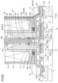
- FIG. 1 is a longitudinal sectional view showing an embodiment of a pilot-type solenoid valve as a pilot-type control valve according to the present invention.
- FIG. 1 is a cross-sectional view along the plane in which the left side of the O line passes through the center of the connector portion 56 toward the paper surface, and the right side of the O line is a cross-sectional view of the vertical surface toward the paper surface.
- the gap formed between the members, the separation distance between the members, and the like are large in comparison with the dimensions of the respective constituent members in order to facilitate understanding of the invention and for convenience in drawing. Or it may be drawn small.
- the pilot type solenoid valve 1 of the illustrated embodiment is used, for example, in a heat pump type cooling and heating system such as a car air conditioner, and mainly includes a bottomed short cylindrical valve body 10 having an inlet 11 and an outlet 12; An electromagnetic actuator (lifting and lowering drive device) 50 provided on the upper side of the valve main body 10 is provided.
- a heat pump type cooling and heating system such as a car air conditioner
- a cylindrical portion 13 provided with an outlet 12 with a main valve seat 12a is formed (in the illustrated example, integrally formed), and orthogonal to the outlet 12;
- a lateral hole-like inlet 11 is provided on the side thereof.
- a lid member 14 made of a substantially dome-shaped magnetic metal (for example, iron or the like) is attached to the upper portion of the valve main body 10 so as to close the top opening of the valve main body 10.
- the lower end of the suction element 53 of the electromagnetic actuator 50 described later is internally fitted in substantially the center of the ceiling portion 14a of the lid member 14 and the pilot valve body 40 (the lower large diameter portion 43 thereof) is inserted.
- a hole 14c is provided.
- a flange portion 14b extends (downwardly) on the outer peripheral portion of the ceiling portion 14a, and the lid member 14 is fixed to (the upper portion of) the valve main body 10 via the flange portion 14b.
- the lid member 14 has the flange portions 14 b of the lid member 14 fastened and fixed to a plurality of mounting portions 10 a integrally provided on the outer periphery of the valve main body 10 and substantially symmetrical with respect to the axis O. As a result, the valve body 10 is assembled.
- a main valve body (also referred to as a diaphragm valve body) 20 having a diaphragm 21 is accommodated in the valve body 10, specifically, in a storage chamber 16 defined by the valve body 10 and the lid member 14 so as to be elastically deformable.
- the storage chamber 16 is partitioned by the main valve body 20 into a main valve chamber 17 and a back pressure chamber 18.
- a pilot passage (a pilot valve port) 39 with a pilot valve seat 39a for escaping the pressure of the back pressure chamber 18 to the outlet 12 penetrates in the vertical direction (direction of the axis O) at the central portion of the main valve body 20.
- the pilot passage 39 is opened and closed by a pilot valve body portion 40a of a pilot valve body 40 described later.
- a pressure supply passage for equalizing pressure from the main valve chamber 17 or the inlet 11 to the back pressure chamber 18 at a position separated from the central portion of the main valve body 20 (a position outside the A pressure passage) 19 is also provided.
- the main valve body 20 is reinforced with a diaphragm 21 made of, for example, an elastic member such as rubber or Teflon (registered trademark), and a disc-like stopper 33 made of, for example, hard resin or metal. It is comprised with the member 30, and they are integrally formed by insert molding etc., for example.
- the diaphragm 21 and the reinforcing member 30 are integrated by insert molding, but it is sufficient if the diaphragm 21 and the reinforcing member 30 are fixed.
- the diaphragm 21 may be partially formed on the reinforcing member 30. A part of or may be fitted or fixed with an adhesive.
- the reinforcing member 30 is formed to have a larger diameter than the outlet 12, and the central portion of the pilot passage 39 (the central portion of the pilot passage 39 (see FIGS. 2A and 2B together with FIG. 1). And a through hole 32 for passing an elastic member constituting the diaphragm 21 when the main valve body 20 is formed.
- four through holes 32 having a generally fan-shaped planar view are provided at substantially equal angular intervals around the center hole 31 in the reinforcing member 30.
- a stopper 33 is provided so as to protrude.
- the stopper 33 prevents the pilot valve seat 39a provided on (the diaphragm 21 of) the main valve body 20 from colliding with the pilot valve body 40 or the like when the valve is opened (that is, when the main valve body 20 is lifted).
- the height is set higher than the height of the upper seal portion 24 of the diaphragm 21 described later.
- four substantially rectangular stoppers 33 are provided outside the through holes 32 of the reinforcing member 30 at substantially equal angular intervals.
- the stopper 33 is integrally formed with the reinforcing member 30, it may be formed separately (in other words, as a separate part) from the reinforcing member 30.
- the stopper may be formed on, for example, the diaphragm 21 or the ceiling portion 14 a of the lid member 14 or the like.
- the upper communication hole (pressure equalizing hole) constituting the pressure supply passage 19 (upper half)
- the diaphragm 21 basically has a relatively thick disk-like lower seal portion 22 formed on the lower surface side of the reinforcing member 30, and the outer periphery of the lower seal portion 22 (that is, the diaphragm A relatively thin elastically deforming portion 23 extended to the periphery of the inner wall 21), an annular upper seal portion 24 formed around the center hole 31 on the upper surface side of the reinforcing member 30 and on the through hole 32; A connecting portion (four connecting portions in this example) 25 formed in the through hole 32 of the reinforcing member 30 and connecting the lower seal portion 22 and the upper seal portion 24 is formed.
- a central hole 26 constituting (the lower part of) the pilot passage 39 is provided in the central portion of the lower seal portion 22, and the inner periphery of the upper seal portion 24 and the central hole 31 of the reinforcing member 30 and the lower portion are formed.
- the pilot passage 39 is formed by the central hole 26 of the side seal portion 22.
- a lower communication hole (also referred to as a pressure equalizing hole) 27 constituting a pressure supply passage 19 (lower half) is provided in the vicinity of the outer periphery of the lower seal portion 22.
- the pressure supply passage 19 is formed by the lower communication hole 27 and the upper communication hole 34 of the reinforcing member 30.
- the upper communication hole 34 of the reinforcement member 30 is slightly smaller than the lower communication hole 27 of the lower seal portion 22, and the passage diameter of the pilot passage 39 (the inner diameter of the upper seal portion 24, the reinforcement member 30
- the hole diameter of the central hole 31 and the hole diameter of the central hole 26 of the lower seal portion 22 are determined from the (minimum) passage diameter of the pressure supply passage 19 (here, the hole diameter of the upper communication hole 34 of the reinforcing member 30) It is slightly larger.
- the lower surface of the lower seal portion 22 of the diaphragm 21 constituting the main valve body 20 (in the illustrated example, an annular portion slightly inward of the lower communication hole 27 and slightly outward of the connecting portion 25)
- the main valve body 20a opens and closes the outlet 12 by contacting and separating the outlet 12 (the upper main valve seat 12a), and the upper surface of the upper seal 24 (in the illustrated example, from the outer edge of the upper seal 24)
- a pilot valve seat 39 a which contacts and separates the pilot valve body 40 (the pilot valve body portion 40 a at the lower end thereof) connected to the plunger 58 of the electromagnetic actuator 50. It is assumed.
- a diaphragm receiving portion 10 b is provided at the upper end of the valve body 10, and (the diaphragm 21 of the main valve body 20 is disposed to cover the top opening of the valve body 10).
- An outer peripheral portion (more specifically, a thick portion formed on the outer periphery of the elastically deformable portion 23) of (the elastically deformable portion 23) has a diaphragm receiving portion 10b and a lid member 14 provided on the upper end of the valve main body 10.
- the back pressure chamber 18 is formed on the upper side of the main valve body 20 in the storage chamber 16 by being pinched and held by the flange portion 14 b provided on the outer peripheral portion of the main valve body. 17 are formed.
- the pressure chamber 18 is in communication, and therefore the pilot passage 39 is closed by the pilot valve body 40 a of the pilot valve body 40, the inlet 11, the main valve chamber 17, and the back pressure chamber 18 are , High pressure fluid will be filled.
- the pressure supply passage 19 for supplying the pressure of the main valve chamber 17 to the inlet 11 to the back pressure chamber 18 is provided in the main valve body 20, but the pressure supply passage 19 Of course, it may be provided in the valve body 10 etc. other than the valve body 20.
- the diaphragm 21 and the reinforcing member 30 as described above are integrally formed, for example, by insert molding, whereby the rigidity of the diaphragm 21 by the reinforcing member 30 (especially, the main valve body portion 20a of the lower seal portion 22 or the upper side The strength of the pilot valve seat 39a at the seal portion 24 is maintained.
- An electromagnetic actuator (solenoid) 50 is mounted on and fixed to the upper portion of the valve body 10.
- the electromagnetic actuator 50 includes a resin coil bobbin 52 around which a solenoid coil 51 is wound.
- the coil bobbin 52 has a cylindrical tubular body 52a on which the solenoid coil 51 is encased, and a pair of flanges for regulating the variation of the solenoid coil 51 at the upper end and the lower end of the tubular body 52a. (The upper flange 52b and the lower flange 52c) are integrally formed.
- a cylindrical plunger 58 made of magnetic metal and a suction element 53 are disposed to face each other in the vertical direction on the inner periphery of (the cylindrical body 52a of the coil bobbin 52), and (the outer periphery of) the plunger 58
- the magnetic pole 59 made of a cylindrical body made of metal is covered.
- the cylindrical suction element 53 is disposed on the lower inner periphery of (the cylindrical body 52a of the coil bobbin 52), and the lower part of the suction element 53 is the lower end (opening) of the coil bobbin 52 (the cylindrical body 52a) It protrudes inside and is fixed to the fitting hole 14c of the lid member 14 by press fitting, caulking or the like.
- a stepped insertion hole (upper small diameter insertion hole 53a and lower large diameter insertion hole 53b) for inserting the lower portion of the pilot valve body 40 is provided in the suction element 53 along the vertical direction (the direction of the axis O). ing.
- the plunger 58 is disposed movably in the vertical direction (direction of the axis O) (on the both sides of the magnetic pole 59) on the inner peripheral upper portion of (the cylindrical body 52a of the coil bobbin 52).
- the cylindrical magnetic pole 59 is internally fitted on the inner peripheral upper portion of (the cylindrical body 52a of the coil bobbin 52), and the plunger 58 is inserted inside the magnetic pole 59 movably along the axis O direction. ing.
- the hollow portion formed inside the coil bobbin 52 (the cylindrical body portion 52a of the coil bobbin 52 (in the coil device 49 in which the solenoid coil 51 is wound around the coil bobbin 52))
- the wall surface facing the hollow portion is used as the inner wall surface of the plunger chamber 60.
- the plunger 58 is provided with a stepped insertion hole (upper small diameter insertion hole 58a and lower large diameter insertion hole 58b) for inserting the upper portion of the pilot valve body 40 along the vertical direction (direction of the axis O). There is.
- the magnetic pole 59 has a flange portion 59a protruding from the upper end thereof (outwardly) held between the upper surface of the coil bobbin 52 and the lower surface of (the ceiling portion 55a of the housing 55 described later) It is fixedly arranged between the plunger 58 and the plunger 58.
- a resin mold cover 54 is disposed to cover the coil bobbin 52 (and the solenoid coil 51 mounted on the coil bobbin 52), and the solenoid coil 51, the coil bobbin 52, and the suction element 53 are disposed outside the mold cover 54.
- the plunger 58 and the like are covered by a substantially gate-shaped housing 55.
- the housing 55 is made of a magnetic material (for example, iron or the like) in which a yoke surrounding the outer periphery of the coil device 49 including the solenoid coil 51, the coil bobbin 52, and the mold cover 54 is integrated.
- the housing 55 has a rectangular flat ceiling 55a covering the upper portion of the mold cover 54 so as to close the ceiling of the plunger chamber 60, as can be seen well with reference to FIG. 3 and FIG.
- a side leg 55b which extends downward from both sides of the portion 55a and covers the side (both sides) of the mold cover 54, and a valve is provided via a mounting leg 55c provided at the lower end of the side leg 55b. It is fixed to (the upper part of) the main body 10.
- the housing 55 holds the flange portion 14b of the lid member 14 between the attachment leg 55c of the housing 55 and the upper portion of the valve main body 10 (in other words, the flange portion of the lid member 14)
- the mounting leg 55c of the housing 55 is fastened and fixed to the mounting portion 10a of the valve main body 10 with bolts 15 while pinching 14b, so that the cover member 14 (flange portion 14b) and the cover member 14 (
- the valve body 10 is assembled in a state of being (magnetically) connected to the flange portion 14 b) of the valve body 10.
- a connector portion 56 is integrally formed on (the upper end side portion of) the mold cover 54, and an external terminal 57 for energizing the solenoid coil 51 is provided in a projecting manner inside the connector portion 56.
- the plunger 58 disposed in the plunger chamber 60 is connected to a stepped shaft-like pilot valve body 40 that opens and closes the pilot passage 39 of the main valve body 20 according to the energized state of the solenoid coil 51.
- the pilot valve body 40 may be made of resin or metal, for example, but resin is preferable because it is lightweight.
- the pilot valve body 40 is inserted from the upper side into the upper small diameter portion 41 inserted into the upper small diameter insertion hole 58a of the plunger 58, and the upper end is inserted into the lower large diameter insertion hole 58b of the plunger 58
- An intermediate body portion 42 inserted into the small diameter insertion hole 53a, and a lower large diameter portion 43 inserted into the lower large diameter insertion hole 53b of the suction element 53 are provided.
- the outer diameter of the lower large diameter portion 43 is slightly larger than the passage diameter of the pilot passage 39 of the main valve body 20, and slightly smaller than the outer diameter of the upper seal portion 24 of the diaphragm 21 constituting the main valve body 20. It is set to.
- An annular outer peripheral groove 44 is provided on the upper outer periphery (a portion inserted into the lower large diameter insertion hole 58b of the plunger 58) of the intermediate body portion 42 of the pilot valve body 40, and a semicircular washer, for example, The ring-shaped spring receptacle (receiving part) 45 of the structure which put two pieces together is engage
- a spring insertion groove 53c is formed on the inner peripheral surface of (the upper small diameter insertion hole 53a of) the suction element 53 with one end (lower end) closed and the other end (upper end) opened.
- the pilot valve body 40 is always upward (between the upper step surface (lower spring receiving surface) of the spring insertion groove 53 c and the lower surface (upper spring receiving surface) of the spring receiver 45 provided on the pilot valve body 40.
- a compression coil spring (biasing member) 46 which is biased in the valve opening direction) is contracted (so as to be externally inserted into the intermediate body portion 42 of the pilot valve body 40).
- the compression coil spring 46 (the outer peripheral step formed between the upper small diameter portion 41 and the middle body portion 42) of the pilot valve body 40 is inserted into the upper small diameter insertion hole 58a of the plunger 58 and the lower large diameter
- the plunger 58 is pressed against an inner circumferential step formed between the hole 58 b and connected with the plunger 58, and the plunger 58 is biased in a direction away from the suction element 53 (upward).
- a stopper that restricts upward movement of the pilot valve body 40 due to the biasing force of the compression coil spring 46 by the outer circumferential step formed between the radial portion 43 and the stopper (in other words, the upward movement limit of the pilot valve body 40 is defined)
- this stopper mechanism is not limited to the above configuration.
- the spring receiver 45 provided on the pilot valve body 40 may be made of metal or resin, for example, the suction force of the pilot valve body 40 toward the suction element 53 is enhanced by making it of magnetic material, for example. be able to.
- the spring receiving portion (receiving portion) 45 is formed separately (as a separate part) from the pilot valve body 40, it is of course possible to be integrally formed with the pilot valve body 40. It is. For example, a step in the radial direction may be provided on the surface of the intermediate body portion 42 of the pilot valve body 40, and this step may be used as a spring receiving portion (receiving portion).
- the lower portion of the lower large diameter portion 43 of the pilot valve body 40 is formed in a cylindrical shape, and a tapered surface (also referred to as a chamfered portion) 43b formed of a frusto-conical surface at the lower inner periphery of the cylindrical portion 43a.
- the tip end (outer end) portion of the tapered surface 43b contacts and separates from the pilot valve seat 39a formed on the main valve body 20 (upper seal portion 24 of the diaphragm 21) to open and close the pilot passage 39 Pilot valve body 40a.
- the outlet 12 of the valve body 10, the main valve body 20 (the pilot passage 39), the coil bobbin 52 (the tubular body 52a of the coil bobbin 52), the suction element 53, the plunger 58, the magnetic pole 59, and the pilot valve body 40 are arranged on the same axis O.
- the solenoid coil 51 when the solenoid coil 51 is energized (the suction coil 53, the plunger 58, the housing 55, the cover member 14, etc., the inner peripheral side of the solenoid coil 51, A magnetic path is formed on the outer peripheral side)
- the magnetic attraction generated by the solenoid coil 51 excites the attractor 53 and the plunger 58, and as shown in FIG. 4A, the plunger 58 resists the biasing force of the compression coil spring 46.
- the suction valve 53 sucks and moves downward, and the pilot valve body 40 is depressed accordingly, and the pilot valve body portion 40 a of the pilot valve body 40 is provided on the main valve body 20.
- the pilot passage 39 is closed by being pressed (seated) on the seat 39a.
- the pilot valve body 40 presses the main valve body 20 downward (in the valve closing direction) (against the elastic force (pushing-up force) of the diaphragm 21 of the main valve body 20), so the outlet 12 is also closed. .
- the high pressure fluid introduced from the inlet 11 to the main valve chamber 17 is not discharged to the outlet 12, but the high pressure fluid is back pressure through the pressure supply passage 19 provided in the main valve body 20. Since it is introduced into the chamber 18, the back pressure chamber 18 also has a high pressure, and the main valve body 20 a of the main valve body 20 is strongly pressed against the main valve seat 12 a of the outlet 12.
- the fluid (pressure) in the back pressure chamber 18 is drawn out (relieved) to the outlet 12 through the pilot passage 39, the pressure in the back pressure chamber 18 decreases, and the inlet 11 and the main valve chamber 17 (high pressure) Force that pushes up the main valve body 20 due to the differential pressure generated between the valve and the back pressure chamber 18 (low pressure) and the force that pushes up the main valve body 20 by the elastic force of the diaphragm 21 of the main valve body 20
- the main valve body 20 is pushed up (until the stopper 33 abuts on the ceiling portion of the storage chamber 16 (that is, the ceiling portion 14a of the lid member 14)) as shown in FIG. 4C.
- the outlet 12 is open.
- the compression coil spring (biasing member) 46 is interposed between the spring receiver (receiver) 45 provided on the pilot valve body 40 and the suction member 53. Because the pilot valve body 40 is pressed against the plunger 58 by the biasing force of the compression coil spring 46 and the plunger 58 is biased in the direction away from the suction bar 53, the pilot valve body 40 is Since it is not necessary to connect and fix them, and the strength (stiffness) of the pilot valve body 40 itself can be reduced, weight increase can be avoided. Further, since the suction force required for the operation of the plunger 58 and the pilot valve body 40 can be reduced, weight reduction can also be achieved by this. Furthermore, since the process of connecting and fixing the pilot valve body 40 to the plunger 58 is not necessary, the number of assembling steps can be reduced, and the assembling process can be simplified to improve the assemblability.
- the main valve body (diaphragm valve body) 20 having the diaphragm 21 is adopted, but as the main valve body 20, a main valve body of another type (for example, a piston type etc.) can be applied There is no need to elaborate.
- the electromagnetic actuator (solenoid) 50 utilizing an electromagnetic force is adopted as the elevation drive device for raising and lowering the pilot valve body 40, but instead of the plunger 58, an electric actuator as the elevation drive device
- the pilot valve body 40a provided at the lower end of the valve shaft while inserting the upper end portion of the valve shaft (member provided with the pilot valve body 40) into this member using a member that is raised and lowered by the electric motor (stepping motor) You may employ
- a compression coil spring 46 as a biasing member be disposed between the valve body (or the lift drive fixed to the valve body) and a spring receiver provided on the valve shaft.
Landscapes
- Engineering & Computer Science (AREA)
- General Engineering & Computer Science (AREA)
- Mechanical Engineering (AREA)
- Magnetically Actuated Valves (AREA)
- Fluid-Driven Valves (AREA)
Abstract
軽量化に寄与するとともに、組立工数の削減や組立性の向上を図ることのできるパイロット式制御弁を提供する。パイロット弁体40に設けられたばね受け45と吸引子53との間に圧縮コイルばね46が介装され、その圧縮コイルばね46の付勢力によって、パイロット弁体40がプランジャ58に押し付けられ、プランジャ58が吸引子53から離れる方向に付勢される。
Description
本発明は、ヒートポンプ式冷暖房システム等に使用するのに好適なパイロット式制御弁に係り、特に、パイロット弁体を昇降駆動し、このパイロット弁体に応動して大口径の主弁口を主弁体で開閉するようにされたパイロット式制御弁に関する。
電磁式アクチュエータ(ソレノイド)によりパイロット弁体を駆動し、このパイロット弁体に応動して大口径の主弁口を主弁体で開閉するようにされたパイロット式電磁弁としては、例えば特許文献1に所載のように、ピストン型の主弁体と、該主弁体が摺動自在に嵌挿されるとともに、該主弁体により背圧室と主弁室とに仕切られた嵌挿室とを備え、前記主弁体に前記背圧室の圧力を流出口へ逃がすためのパイロット通路が設けられるとともに、該パイロット通路を前記電磁式アクチュエータにより昇降駆動されるパイロット弁体で開閉するようにされたものが知られている。
ところで、上記特許文献1に所載の如くの従来のパイロット式電磁弁では、通常、電磁式アクチュエータにより昇降駆動されるプランジャに、先端にシール部材が取り付けられた金属製のパイロット弁体を圧入・かしめ等により連結固定し、プランジャと吸引子との間に付勢部材としての圧縮コイルばねを縮装して、プランジャ(及びパイロット弁体)を吸引子から離れる方向に付勢している。
そのため、上記従来のパイロット式電磁弁では、プランジャに連結固定されるパイロット弁体自体の強度(剛性)が必要となり、重量増加を招くとともに、プランジャ(及びパイロット弁体)を吸引子側に引き寄せるための吸引力も大きくなるという問題があった。また、圧入工程やかしめ工程といったプランジャにパイロット弁体を連結固定する工程が必要となり、組立工数が増加するとともに、組立工程が煩雑化するという問題もあった。
本発明は、上記事情に鑑みてなされたものであって、その目的とするところは、軽量化に寄与するとともに、組立工数の削減や組立性の向上を図ることのできるパイロット式制御弁を提供することを目的とする。
上記の目的を達成すべく、本発明に係るパイロット式制御弁は、基本的に、流入口及び流出口が設けられた弁本体と、前記流出口を開閉するための主弁体と、該主弁体が配在されるとともに、該主弁体によって主弁室と背圧室とに仕切られた収納室と、前記主弁室ないし前記流入口の圧力を前記背圧室に供給するための圧力供給通路とを備え、前記主弁体に前記背圧室の圧力を前記流出口へ逃がすためのパイロット通路が設けられ、該パイロット通路を電磁式アクチュエータにより昇降駆動されるパイロット弁体で開閉することにより、該パイロット弁体に応動して前記流出口を前記主弁体で開閉するようにされ、前記パイロット弁体に設けられた受け部と前記電磁式アクチュエータの吸引子との間に付勢部材が介装され、該付勢部材の付勢力によって、前記パイロット弁体が前記電磁式アクチュエータのプランジャに押し付けられ、前記プランジャが前記吸引子から離れる方向に付勢されていることを特徴としている。
好ましい態様では、前記受け部は、前記パイロット弁体と一体もしくは別体に設けられる。
別の好ましい態様では、前記受け部は、前記パイロット弁体に設けられた外周溝に装着される。
他の好ましい態様では、前記受け部は、前記プランジャに設けられた挿入穴内に配置される。
他の好ましい態様では、前記パイロット弁体と前記吸引子との間に、前記付勢部材の付勢力による前記パイロット弁体の移動限界を定めるストッパ機構が設けられる。
前記パイロット弁体は、好ましくは、樹脂製である。
前記受け部は、好ましくは、磁性材料で作製される。
また、本発明に係るパイロット式制御弁は、基本的に、流入口及び流出口が設けられた弁本体と、前記流出口を開閉するための主弁体と、該主弁体が配在されるとともに、該主弁体によって主弁室と背圧室とに仕切られた収納室と、前記主弁室ないし前記流入口の圧力を前記背圧室に供給するための圧力供給通路とを備え、前記主弁体に前記背圧室の圧力を前記流出口へ逃がすためのパイロット通路が設けられ、該パイロット通路を昇降駆動装置により昇降駆動されるパイロット弁体で開閉することにより、該パイロット弁体に応動して前記流出口を前記主弁体で開閉するようにされ、前記パイロット弁体に設けられた受け部と前記弁本体ないし前記昇降駆動装置との間に付勢部材が介装され、該付勢部材の付勢力によって、前記パイロット弁体が前記弁本体ないし前記昇降駆動装置に押し付けられるようにされていることを特徴とするパイロット式制御弁である。
本発明によれば、パイロット弁体に設けられた受け部と吸引子との間に付勢部材が介装され、その付勢部材の付勢力によって、パイロット弁体がプランジャに押し付けられ、プランジャが吸引子から離れる方向に付勢されるので、圧入・かしめ等によってパイロット弁体をプランジャに連結固定する必要が無くなり、パイロット弁体自体の強度(剛性)が低く抑えられるため、重量増加を回避できる。また、プランジャ及びパイロット弁体の稼働に要する吸引力を小さくできるため、これによっても、軽量化を図ることができる。さらに、パイロット弁体をプランジャに連結固定する工程が不要となるため、組立工数を削減できるとともに、組立工程を簡素化して組立性を向上させることができる。
以下、本発明の実施形態を図面を参照しながら説明する。
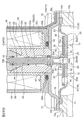
図1は、本発明に係るパイロット式制御弁としてのパイロット式電磁弁の一実施形態を示す縦断面図である。図1は、紙面に向かってO線の左側がコネクタ部56の中心を通る面に沿った断面図であり、O線の右側が紙面に向かって垂直な面の断面図である。
なお、本明細書において、上下、左右、前後等の位置、方向を表わす記述は、説明が煩瑣になるのを避けるために図面に従って便宜上付けたものであり、実際の使用状態での位置、方向を指すとは限らない。本明細書では、昇降駆動装置としての電磁式アクチュエータ(ソレノイド)が配置された側を上側、弁本体が配置された側を下側としている。
また、各図において、部材間に形成される隙間や部材間の離隔距離等は、発明の理解を容易にするため、また、作図上の便宜を図るため、各構成部材の寸法に比べて大きくあるいは小さく描かれている場合がある。
図示実施形態のパイロット式電磁弁1は、例えばカーエアコン等のヒートポンプ式冷暖房システム等に用いられるもので、主に、流入口11及び流出口12を有する底部付き短円筒状の弁本体10と、弁本体10の上側に設けられた電磁式アクチュエータ(昇降駆動装置)50とを備えている。
弁本体10の底部中央には、主弁座12a付きの流出口12が設けられた円筒部13が形成(図示例では、一体に形成)されるとともに、前記流出口12に直交するように、その側部に横穴状の流入口11が設けられている。
弁本体10の上部には、該弁本体10の上面開口を塞ぐように概略ドーム状の磁性金属(例えば、鉄等)からなる蓋部材14が取り付けられている。この蓋部材14の天井部14aの略中央には、後述する電磁式アクチュエータ50の吸引子53の下端が内嵌されるとともにパイロット弁体40(の下部大径部43)が挿通される嵌合穴14cが設けられている。また、その天井部14aの外周部には(下向きに)フランジ部14bが延設されており、このフランジ部14bを介して当該蓋部材14は弁本体10(の上部)に固定されている。図示例では、蓋部材14は、弁本体10の外周に一体に且つ軸線Oに対して略対称に設けられた複数の取付部10aに前記蓋部材14のフランジ部14bをボルト類15で締結固定することにより、弁本体10に組み付けられる。
前記弁本体10内、具体的には、弁本体10と蓋部材14により画成された収納室16には、ダイヤフラム21を有する主弁体(ダイヤフラム弁体ともいう)20が弾性変形自在に収納され、該主弁体20により前記収納室16が主弁室17と背圧室18とに仕切られている。主弁体20の中央部には、背圧室18の圧力を流出口12へ逃がすためのパイロット弁座39a付きのパイロット通路(パイロット弁口)39が上下方向(軸線O方向)に貫通するように設けられ、後述するパイロット弁体40のパイロット弁体部40aにより前記パイロット通路39を開閉するようになっている。また、主弁体20の中央部から離間した位置(流出口12より外側の位置)には、主弁室17ないし流入口11の圧力を背圧室18に供給するための圧力供給通路(均圧通路ともいう)19が設けられている。
詳細には、前記主弁体20は、例えばゴムあるいはテフロン(登録商標)等の弾性部材から作製されたダイヤフラム21と、例えば硬質の樹脂あるいは金属等から作製された円板状のストッパ33付き補強部材30とで構成され、それらが例えばインサート成形等により一体化されて形成されている。なお、本例では、ダイヤフラム21と補強部材30をインサート成形にて一体化した構成としたが、ダイヤフラム21と補強部材30とが固定されていればよく、例えば補強部材30の一部にダイヤフラム21の一部を嵌合、又は接着剤で固定してもよい。
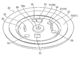
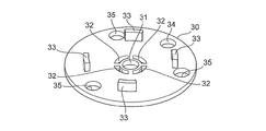
より詳しくは、前記補強部材30は、流出口12より大径に形成されるとともに、図1とともに図2A、Bを参照すればよく分かるように、その中央部に、パイロット通路39(の中央部分)を構成する中心穴31が開設され、該中心穴31の周囲に、前記主弁体20の成形時にダイヤフラム21を構成する弾性部材を通過させるための通し穴32が貫設されている。本例では、平面視略扇形の通し穴32が、前記補強部材30における中心穴31周りに略等角度間隔に4個設けられている。
また、前記補強部材30の上面における通し穴32周りには、収納室16の天井面(つまり、蓋部材14の天井部14aの下面)に当接して主弁体20の最大変形(リフト)位置を定めるストッパ33が突設されている。このストッパ33は、開弁時(つまり、主弁体20のリフト時)に当該主弁体20(のダイヤフラム21)に設けられたパイロット弁座39aがパイロット弁体40等に衝突するのを阻止すべく、その高さが、後述するダイヤフラム21の上側シール部24の高さより高く設定されている。本例では、略矩形状のストッパ33が、前記補強部材30における通し穴32の外側に略等角度間隔に4個設けられている。
なお、ここでは、前記ストッパ33が補強部材30と一体に成形されているが、補強部材30と別体に(言い換えれば、別部品として)形成しても良い。また、前記ストッパを、例えば、ダイヤフラム21や蓋部材14の天井部14a等に形成しても良いことは勿論である。
さらに、前記補強部材30の外周付近(図2A、Bに示す例では、隣り合うストッパ33の中間付近)には、圧力供給通路19(の上半分)を構成する上側連通穴(均圧孔ともいう)34が開設されるとともに、当該補強部材30とダイヤフラム21との固着力を高めるためにダイヤフラム21を構成する弾性部材の一部が侵入して充填される導入穴(図2A、Bに示す例では、3個)35が開設されている。
一方、前記ダイヤフラム21は、基本的に、前記補強部材30の下面側に形成される比較的肉厚の円板状の下側シール部22と、該下側シール部22の外周(つまり、ダイヤフラム21の周縁)に延設される比較的肉薄の弾性変形部23と、前記補強部材30の上面側における中心穴31周り且つ通し穴32上に形成される円環状の上側シール部24と、前記補強部材30の通し穴32内に形成されて下側シール部22と上側シール部24とを連結する連結部(本例では、4箇所の連結部)25とからなっている。
下側シール部22の中央部には、パイロット通路39(の下部)を構成する中央穴26が設けられており、前記上側シール部24の内周と前記補強部材30の中心穴31と前記下側シール部22の中央穴26とで前記パイロット通路39が形成されている。
また、下側シール部22の外周付近には、圧力供給通路19(の下半分)を構成する下側連通穴(均圧孔ともいう)27が設けられており、前記下側シール部22の下側連通穴27と前記補強部材30の上側連通穴34とで前記圧力供給通路19が形成されている。図示例では、補強部材30の上側連通穴34は、下側シール部22の下側連通穴27より若干小さくされるとともに、前記パイロット通路39の通路径(上側シール部24の内径、補強部材30の中心穴31の穴径、下側シール部22の中央穴26の穴径)は、圧力供給通路19の(最小)通路径(ここでは、補強部材30の上側連通穴34の穴径)より若干大きくされている。
本実施形態では、前記主弁体20を構成するダイヤフラム21における下側シール部22の下面(図示例では、下側連通穴27より若干内側かつ連結部25より若干外側の円環状部分)が、流出口12(の上端の主弁座12a)に接離して当該流出口12を開閉する主弁体部20aとされ、前記上側シール部24の上面(図示例では、上側シール部24の外縁より内側、かつ、連結部25より若干内側の円環状部分)が、電磁式アクチュエータ50のプランジャ58に連結されたパイロット弁体40(の下端のパイロット弁体部40a)に接離するパイロット弁座39aとされる。
前記弁本体10の上端には、ダイヤフラム受け部10bが設けられており、弁本体10の上面開口を覆うように主弁体20(のダイヤフラム21)が配在され、該主弁体20のダイヤフラム21(の弾性変形部23)の外周部(より詳しくは、弾性変形部23の外周に形成された肉厚部)が、前記弁本体10の上端に設けられたダイヤフラム受け部10bと蓋部材14の外周部に設けられたフランジ部14bとで挟圧保持されることで、収納室16における主弁体20より上側に背圧室18が形成され、主弁体20より下側に主弁室17が形成されている。
前記のように、本例では、圧力供給通路19を構成する下側シール部22の下側連通穴27と補強部材30の上側連通穴34とを介して流入口11ないし主弁室17と背圧室18とが連通しており、したがって、パイロット通路39がパイロット弁体40のパイロット弁体部40aで閉じられている状態においては、流入口11、主弁室17、背圧室18には、高圧の流体が充満することになる。
なお、本例では、主弁室17ないし流入口11の圧力を背圧室18に供給するための圧力供給通路19が主弁体20に設けられているが、前記圧力供給通路19は、主弁体20以外の弁本体10等に設けても良いことは勿論である。
上記した如くのダイヤフラム21と補強部材30とが例えばインサート成形等により一体に形成されることで、当該補強部材30によってダイヤフラム21の剛性(特に、下側シール部22における主弁体部20aや上側シール部24におけるパイロット弁座39aの強度)が保持されることになる。
電磁式アクチュエータ(ソレノイド)50は、前記弁本体10の上部に載置固定されている。
前記電磁式アクチュエータ50は、ソレノイドコイル51が巻装された樹脂製のコイルボビン52を備える。このコイルボビン52は、ソレノイドコイル51が外装される円筒状の筒状胴体部52aを有するとともに、その筒状胴体部52aの上端部及び下端部に、ソレノイドコイル51のばらつきを規制する一対のフランジ部(上側フランジ部52b、下側フランジ部52c)が一体的に形成されている。
コイルボビン52(の筒状胴体部52a)の内周には、磁性金属からなる円筒状のプランジャ58と吸引子53とが上下方向で対向配置されるとともに、前記プランジャ58(の外周)に、磁性金属からなる円筒体で作製された磁極59が外装されている。
前記円筒状の吸引子53は、コイルボビン52(の筒状胴体部52a)の内周下部に配置され、この吸引子53の下部が、コイルボビン52(の筒状胴体部52a)の下端(開口)から突出して前記蓋部材14の嵌合穴14cに圧入・かしめ等により内嵌固定されている。この吸引子53には、パイロット弁体40の下部を挿通するための段付きの挿通穴(上部小径挿通穴53a、下部大径挿通穴53b)が上下方向(軸線O方向)に沿って設けられている。
一方、前記プランジャ58は、コイルボビン52(の筒状胴体部52a)の内周上部に、(間に磁極59を挟んで)上下方向(軸線O方向)に移動自在に配在されている。言い換えれば、コイルボビン52(の筒状胴体部52a)の内周上部に円筒状の磁極59が内嵌され、その磁極59の内側に前記プランジャ58が軸線O方向に沿って移動自在に内挿されている。すなわち、ここでは、コイルボビン52(の筒状胴体部52a)の内側(コイルボビン52にソレノイドコイル51が巻装されたコイル装置49内)に形成された中空部が、前記プランジャ58が昇降自在に配置されるプランジャ室60とされ、その中空部に面する壁面が前記プランジャ室60の内壁面として用いられている。このプランジャ58には、パイロット弁体40の上部を挿入するための段付きの挿入穴(上部小径挿入穴58a、下部大径挿入穴58b)が上下方向(軸線O方向)に沿って設けられている。
なお、前記磁極59は、その上端から(外向きに)突設されたフランジ部59aがコイルボビン52の上面と後述するハウジング55(の天井部55a)の下面とで挟持されて、前記コイルボビン52とプランジャ58との間に固定配置されている。
前記コイルボビン52(及び該コイルボビン52に外装されたソレノイドコイル51)を覆うように樹脂製のモールドカバー54が配在され、該モールドカバー54の外側において、ソレノイドコイル51、コイルボビン52、吸引子53、及びプランジャ58等が概略門型のハウジング55により覆われている。
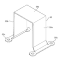
より詳しくは、前記ハウジング55は、前記ソレノイドコイル51、コイルボビン52、モールドカバー54からなるコイル装置49の外周を囲うヨークが一体とされた磁性材料(例えば、鉄等)で作製されている。このハウジング55は、図1とともに図3を参照すればよく分かるように、前記プランジャ室60の天井部を閉塞するように前記モールドカバー54の上部を覆う矩形平板状の天井部55aと、該天井部55aの両側部から下方に延びて前記モールドカバー54の側部(両側部)を覆う側脚部55bとで構成され、その側脚部55bの下端に設けられた取付脚55cを介して弁本体10(の上部)に固定されている。図示例では、このハウジング55は、当該ハウジング55の取付脚55cと弁本体10の上部との間に前記蓋部材14のフランジ部14bを挟んだ状態で(言い換えれば、前記蓋部材14のフランジ部14bを挟圧しながら)前記弁本体10の取付部10aに前記ハウジング55の取付脚55cをボルト類15で締結固定することにより、前記蓋部材14(のフランジ部14b)とともに且つ前記蓋部材14(のフランジ部14b)と(磁気的に)接続された状態で弁本体10に組み付けられている。
前記ハウジング55の天井部55aとモールドカバー54の上部と磁極59のフランジ部59aとで囲まれる空間(具体的には、モールドカバー54の上面において磁極59のフランジ部59aの外側に設けられた環状溝54a)、並びに、モールドカバー54の下部と蓋部材14の天井部14aとの間(具体的には、モールドカバー54の下面における内周付近に設けられた環状溝54b)にはそれぞれ、シール部材としてのOリング61、62が圧縮状態で装着されている。
また、モールドカバー54(の上端側部)には、コネクタ部56が一体成形され、コネクタ部56の内部には、ソレノイドコイル51に通電するための外部端子57が突設されている。
前記プランジャ室60に配在されたプランジャ58には、ソレノイドコイル51の通電状態に応じて前記主弁体20のパイロット通路39を開閉する段付き軸状のパイロット弁体40が連結されている。なお、このパイロット弁体40は、例えば樹脂製でも金属製でも良いが、樹脂製の方が軽量であるので好ましい。
前記パイロット弁体40は、上側から、プランジャ58の上部小径挿入穴58aに嵌挿される上部小径部41、上端側がプランジャ58の下部大径挿入穴58bに内挿されるとともに下端側が吸引子53の上部小径嵌挿穴53aに挿通される中間胴部42、吸引子53の下部大径嵌挿穴53bに内挿される下部大径部43を備えている。下部大径部43の外径は、前記主弁体20のパイロット通路39の通路径より若干大径、かつ、前記主弁体20を構成するダイヤフラム21の上側シール部24の外径より若干小径に設定されている。
パイロット弁体40の中間胴部42の上部外周(プランジャ58の下部大径挿入穴58bに内挿される部分)には環状の外周溝44が設けられ、該外周溝44に、例えば半周状のワッシャを2個合わせた構成のリング状のばね受け(受け部)45が嵌め込まれている。
一方、前記吸引子53(の上部小径嵌挿穴53a)の内周面には、一端(下端)を閉じ且つ他端(上端)を開いたばね挿入溝53cが形成されている。このばね挿入溝53cの上向きの段差面(下側ばね受け面)と前記パイロット弁体40に設けられたばね受け45の下面(上側ばね受け面)との間に、パイロット弁体40を常時上方(開弁方向)に付勢する圧縮コイルばね(付勢部材)46が(パイロット弁体40の中間胴部42に外挿されるようにして)縮装されている。この圧縮コイルばね46の付勢力によって、パイロット弁体40(の上部小径部41と中間胴部42との間に形成される外周段差)がプランジャ58(の上部小径挿入穴58aと下部大径挿入穴58bとの間に形成される内周段差)に押し付けられて当該プランジャ58と連結されるとともに、プランジャ58は吸引子53から離れる方向(上方向)に付勢されている。
ここで、図示例では、吸引子53の上部小径嵌挿穴53aと下部大径嵌挿穴53bとの間に形成される内周段差と、前記パイロット弁体40の中間胴部42と下部大径部43との間に形成される外周段差とによって、前記圧縮コイルばね46の付勢力によるパイロット弁体40の上方移動を規制する(言い換えれば、パイロット弁体40の上方移動限界を定める)ストッパ機構が形成されているが、このストッパ機構は、上記構成に限定されないことは当然である。
また、前記パイロット弁体40に設けられたばね受け45は、例えば金属製でも樹脂製でも良いが、例えば磁性材料で作製することにより、当該パイロット弁体40の吸引子53側への吸引力を高めることができる。また、本例では、前記ばね受け(受け部)45は、パイロット弁体40と別体に(別部品として)形成されているが、パイロット弁体40と一体に形成しても良いことは勿論である。例えば、パイロット弁体40の中間胴部42の表面に径方向の段差を設け、この段差をばね受け(受け部)としてもよい。
前記パイロット弁体40の下部大径部43の上部外周(に設けられた環状溝)には、例えばゴムあるいはテフロン(登録商標)等の合成樹脂で作製されたパッキン(ピストンリング)47が装着されている。
また、本例では、パイロット弁体40の下部大径部43の下部が円筒状に形成されるとともに、その円筒部43aの下端内周に、円錐台面からなるテーパ面(面取り部ともいう)43bが形成されており、そのテーパ面43bの先端(外端)部分が、主弁体20(のダイヤフラム21の上側シール部24)に形成されたパイロット弁座39aに接離してパイロット通路39を開閉するパイロット弁体部40aとされている。
なお、図示例では、弁本体10の流出口12、主弁体20(のパイロット通路39)、コイルボビン52(の筒状胴体部52a)、吸引子53、プランジャ58、磁極59、及びパイロット弁体40等が、同一軸線O上に配置されている。
このような構成とされたパイロット式電磁弁1にあっては、ソレノイドコイル51に通電すると、(吸引子53、プランジャ58、ハウジング55、蓋部材14等を介してソレノイドコイル51の内周側及び外周側に磁路が形成されて)ソレノイドコイル51により発生した磁界により吸引子53及びプランジャ58が励磁され、図4Aに示される如くに、圧縮コイルばね46の付勢力に抗してプランジャ58が吸引子53に吸引されて下方に移動し、これに伴い、パイロット弁体40が押し下げられて当該パイロット弁体40のパイロット弁体部40aが主弁体20に設けられたパイロット通路39のパイロット弁座39aに押し付けられて(着座して)パイロット通路39が閉じられる。それとともに、パイロット弁体40が(主弁体20のダイヤフラム21の弾性力(押し上げる力)に抗して)主弁体20を下方(閉弁方向)に押圧するので、流出口12も閉じられる。
したがって、このときは、流入口11から主弁室17に導入された高圧の流体が流出口12へは導出されないが、この高圧流体が主弁体20に設けられた圧力供給通路19を通じて背圧室18に導入されるので、背圧室18も高圧となり、主弁体20の主弁体部20aが流出口12の主弁座12aに強く押し付けられる。
一方、この閉弁状態からソレノイドコイル51への通電をオフすると、つまり、ソレノイドコイル51に通電しないときには、図4Bに示される如くに、圧縮コイルばね46の付勢力により、パイロット弁体40がプランジャ58とともに押し上げられて上方に移動し、パイロット弁体40のパイロット弁体部40aがパイロット弁座39aから離れてパイロット通路39が開かれる。
これにより、背圧室18の流体(圧力)がパイロット通路39を通じて流出口12へ導出され(逃がされ)、背圧室18の圧力が低下し、流入口11及び主弁室17(高圧)と背圧室18(低圧)との間に生じた差圧力及び主弁体20のダイヤフラム21の弾性力による主弁体20を押し上げる力(開弁させる力)が主弁体20を押し下げる力(閉弁させる力)に打ち勝ち、図4Cに示される如くに、(ストッパ33が収納室16の天井部(つまり、蓋部材14の天井部14a)に当接するまで)主弁体20が押し上げられて、流出口12が開く。
このように、本実施形態のパイロット式電磁弁1では、パイロット弁体40に設けられたばね受け(受け部)45と吸引子53との間に圧縮コイルばね(付勢部材)46が介装され、その圧縮コイルばね46の付勢力によって、パイロット弁体40がプランジャ58に押し付けられ、プランジャ58が吸引子53から離れる方向に付勢されるので、圧入・かしめ等によってパイロット弁体40をプランジャ58に連結固定する必要が無くなり、パイロット弁体40自体の強度(剛性)が低く抑えられるため、重量増加を回避できる。また、プランジャ58及びパイロット弁体40の稼働に要する吸引力を小さくできるため、これによっても、軽量化を図ることができる。さらに、パイロット弁体40をプランジャ58に連結固定する工程が不要となるため、組立工数を削減できるとともに、組立工程を簡素化して組立性を向上させることができる。
なお、上記実施形態では、ダイヤフラム21を有する主弁体(ダイヤフラム弁体)20を採用したが、当該主弁体20としては、その他のタイプ(例えばピストン型等)の主弁体を適用できることは詳述するまでも無い。
また、上記実施形態では、パイロット弁体40を昇降させるための昇降駆動装置として、電磁力を利用した電磁式アクチュエータ(ソレノイド)50を採用したが、プランジャ58に替わり昇降駆動装置としての電動式アクチュエータである電動モータ(ステッピングモータ)により昇降する部材を用い、この部材に弁軸(パイロット弁体40を備えた部材)の上端部を挿入させながら弁軸の下端に設けられたパイロット弁体40aを昇降駆動するようにした電動弁に採用しても良い。この場合、弁本体側(あるいは、弁本体に固定された昇降駆動装置側)と弁軸に設けられたばね受けとの間に、付勢部材としての圧縮コイルばね46が配置されると良い。
1 パイロット式電磁弁
10 弁本体
10b ダイヤフラム受け部
11 流入口
12 流出口
12a 主弁座
13 円筒部
14 蓋部材
16 収納室
17 主弁室
18 背圧室
19 圧力供給通路
20 主弁体
20a 主弁体部
21 ダイヤフラム
22 下側シール部
23 弾性変形部
24 上側シール部
25 連結部
30 補強部材
32 通し穴
33 ストッパ
39 パイロット通路
39a パイロット弁座
40 パイロット弁体
40a パイロット弁体部
41 上部小径部
42 中間胴部
43 下部大径部
44 外周溝
45 ばね受け(受け部)
46 圧縮コイルばね(付勢部材)
47 パッキン(ピストンリング)
49 コイル装置
50 電磁式アクチュエータ(昇降駆動装置)
51 ソレノイドコイル
52 コイルボビン
53 吸引子
54 モールドカバー
55 ハウジング
58 プランジャ
59 磁極
59a フランジ部
60 プランジャ室
61 Oリング
62 Oリング
10 弁本体
10b ダイヤフラム受け部
11 流入口
12 流出口
12a 主弁座
13 円筒部
14 蓋部材
16 収納室
17 主弁室
18 背圧室
19 圧力供給通路
20 主弁体
20a 主弁体部
21 ダイヤフラム
22 下側シール部
23 弾性変形部
24 上側シール部
25 連結部
30 補強部材
32 通し穴
33 ストッパ
39 パイロット通路
39a パイロット弁座
40 パイロット弁体
40a パイロット弁体部
41 上部小径部
42 中間胴部
43 下部大径部
44 外周溝
45 ばね受け(受け部)
46 圧縮コイルばね(付勢部材)
47 パッキン(ピストンリング)
49 コイル装置
50 電磁式アクチュエータ(昇降駆動装置)
51 ソレノイドコイル
52 コイルボビン
53 吸引子
54 モールドカバー
55 ハウジング
58 プランジャ
59 磁極
59a フランジ部
60 プランジャ室
61 Oリング
62 Oリング
Claims (8)
- 流入口及び流出口が設けられた弁本体と、前記流出口を開閉するための主弁体と、該主弁体が配在されるとともに、該主弁体によって主弁室と背圧室とに仕切られた収納室と、前記主弁室ないし前記流入口の圧力を前記背圧室に供給するための圧力供給通路とを備え、前記主弁体に前記背圧室の圧力を前記流出口へ逃がすためのパイロット通路が設けられ、該パイロット通路を電磁式アクチュエータにより昇降駆動されるパイロット弁体で開閉することにより、該パイロット弁体に応動して前記流出口を前記主弁体で開閉するようにされたパイロット式制御弁であって、
前記パイロット弁体に設けられた受け部と前記電磁式アクチュエータの吸引子との間に付勢部材が介装され、該付勢部材の付勢力によって、前記パイロット弁体が前記電磁式アクチュエータのプランジャに押し付けられ、前記プランジャが前記吸引子から離れる方向に付勢されていることを特徴とするパイロット式制御弁。 - 前記受け部は、前記パイロット弁体と一体もしくは別体に設けられていることを特徴とする請求項1に記載のパイロット式制御弁。
- 前記受け部は、前記パイロット弁体に設けられた外周溝に装着されていることを特徴とする請求項1に記載のパイロット式制御弁。
- 前記受け部は、前記プランジャに設けられた挿入穴内に配置されていることを特徴とする請求項1から3のいずれか一項に記載のパイロット式制御弁。
- 前記パイロット弁体と前記吸引子との間に、前記付勢部材の付勢力による前記パイロット弁体の移動限界を定めるストッパ機構が設けられていることを特徴とする請求項1から4のいずれか一項に記載のパイロット式制御弁。
- 前記パイロット弁体は、樹脂製であることを特徴とする請求項1から5のいずれか一項に記載のパイロット式制御弁。
- 前記受け部は、磁性材料で作製されていることを特徴とする請求項1から6のいずれか一項に記載のパイロット式制御弁。
- 流入口及び流出口が設けられた弁本体と、前記流出口を開閉するための主弁体と、該主弁体が配在されるとともに、該主弁体によって主弁室と背圧室とに仕切られた収納室と、前記主弁室ないし前記流入口の圧力を前記背圧室に供給するための圧力供給通路とを備え、前記主弁体に前記背圧室の圧力を前記流出口へ逃がすためのパイロット通路が設けられ、該パイロット通路を昇降駆動装置により昇降駆動されるパイロット弁体で開閉することにより、該パイロット弁体に応動して前記流出口を前記主弁体で開閉するようにされたパイロット式制御弁であって、
前記パイロット弁体に設けられた受け部と前記弁本体ないし前記昇降駆動装置との間に付勢部材が介装され、該付勢部材の付勢力によって、前記パイロット弁体が前記弁本体ないし前記昇降駆動装置に押し付けられるようにされていることを特徴とするパイロット式制御弁。
Applications Claiming Priority (2)
| Application Number | Priority Date | Filing Date | Title |
|---|---|---|---|
| JP2017-162460 | 2017-08-25 | ||
| JP2017162460A JP6879556B2 (ja) | 2017-08-25 | 2017-08-25 | パイロット式制御弁 |
Publications (1)
| Publication Number | Publication Date |
|---|---|
| WO2019039248A1 true WO2019039248A1 (ja) | 2019-02-28 |
Family
ID=65438674
Family Applications (1)
| Application Number | Title | Priority Date | Filing Date |
|---|---|---|---|
| PCT/JP2018/029360 Ceased WO2019039248A1 (ja) | 2017-08-25 | 2018-08-06 | パイロット式制御弁 |
Country Status (2)
| Country | Link |
|---|---|
| JP (1) | JP6879556B2 (ja) |
| WO (1) | WO2019039248A1 (ja) |
Cited By (1)
| Publication number | Priority date | Publication date | Assignee | Title |
|---|---|---|---|---|
| CN117108811A (zh) * | 2023-10-10 | 2023-11-24 | 郑翰林 | 一种先导阀 |
Families Citing this family (1)
| Publication number | Priority date | Publication date | Assignee | Title |
|---|---|---|---|---|
| JP7557669B2 (ja) | 2021-02-16 | 2024-09-30 | パナソニックIpマネジメント株式会社 | 給水電磁弁 |
Citations (3)
| Publication number | Priority date | Publication date | Assignee | Title |
|---|---|---|---|---|
| JP2011169404A (ja) * | 2010-02-18 | 2011-09-01 | Rinnai Corp | 電磁弁 |
| WO2016041650A1 (en) * | 2014-09-19 | 2016-03-24 | Danfoss A/S | Solenoid valve |
| JP2016089969A (ja) * | 2014-11-06 | 2016-05-23 | 株式会社テージーケー | 電磁弁 |
Family Cites Families (2)
| Publication number | Priority date | Publication date | Assignee | Title |
|---|---|---|---|---|
| JP6111082B2 (ja) * | 2013-02-07 | 2017-04-05 | 株式会社不二工機 | 差圧弁付電磁弁 |
| JP6395696B2 (ja) * | 2015-12-16 | 2018-09-26 | 株式会社不二工機 | 可変容量型圧縮機用制御弁 |
-
2017
- 2017-08-25 JP JP2017162460A patent/JP6879556B2/ja active Active
-
2018
- 2018-08-06 WO PCT/JP2018/029360 patent/WO2019039248A1/ja not_active Ceased
Patent Citations (3)
| Publication number | Priority date | Publication date | Assignee | Title |
|---|---|---|---|---|
| JP2011169404A (ja) * | 2010-02-18 | 2011-09-01 | Rinnai Corp | 電磁弁 |
| WO2016041650A1 (en) * | 2014-09-19 | 2016-03-24 | Danfoss A/S | Solenoid valve |
| JP2016089969A (ja) * | 2014-11-06 | 2016-05-23 | 株式会社テージーケー | 電磁弁 |
Cited By (1)
| Publication number | Priority date | Publication date | Assignee | Title |
|---|---|---|---|---|
| CN117108811A (zh) * | 2023-10-10 | 2023-11-24 | 郑翰林 | 一种先导阀 |
Also Published As
| Publication number | Publication date |
|---|---|
| JP6879556B2 (ja) | 2021-06-02 |
| JP2019039513A (ja) | 2019-03-14 |
Similar Documents
| Publication | Publication Date | Title |
|---|---|---|
| WO2013097446A1 (en) | Solenoid valve | |
| CN112747130A (zh) | 一种燃气阀 | |
| JP2019039508A (ja) | パイロット式電磁弁 | |
| WO2019039248A1 (ja) | パイロット式制御弁 | |
| JP6320628B2 (ja) | 電磁弁 | |
| KR20200010335A (ko) | 파일럿식 전자밸브 | |
| KR102043966B1 (ko) | 현가장치의 모드 전환용 솔레노이드 밸브 조립체 | |
| JP6883328B2 (ja) | パイロット式電磁弁 | |
| WO2019039247A1 (ja) | パイロット式制御弁 | |
| CN112747123A (zh) | 一种燃气阀 | |
| US4582088A (en) | Three port solenoid valve | |
| JP6074375B2 (ja) | ダイアフラム弁構造及び電磁弁 | |
| JP6976582B2 (ja) | 電磁弁 | |
| JP6924499B2 (ja) | 電磁弁 | |
| JP2832175B2 (ja) | 電磁弁 | |
| JP2006070990A (ja) | 電動弁 | |
| KR101671950B1 (ko) | 솔레노이드 일체형 액추에이터 | |
| CN118729039A (zh) | 可调式阻尼阀装置 | |
| JP6467649B2 (ja) | 制御弁 | |
| KR101102462B1 (ko) | 고주파 공압식 솔레노이드 밸브 | |
| JP6941086B2 (ja) | 電磁アクチュエータ、およびそれを備えた電磁弁 | |
| JP2021025564A (ja) | 流路切換弁 | |
| JP7130601B2 (ja) | 電磁コイル及び弁装置 | |
| CN112747161B (zh) | 一种燃气比例阀 | |
| JPH0217256Y2 (ja) |
Legal Events
| Date | Code | Title | Description |
|---|---|---|---|
| 121 | Ep: the epo has been informed by wipo that ep was designated in this application |
Ref document number: 18847428 Country of ref document: EP Kind code of ref document: A1 |
|
| NENP | Non-entry into the national phase |
Ref country code: DE |
|
| 122 | Ep: pct application non-entry in european phase |
Ref document number: 18847428 Country of ref document: EP Kind code of ref document: A1 |