WO2019039145A1 - 情報管理システム、情報管理方法およびケアサポートシステム - Google Patents
情報管理システム、情報管理方法およびケアサポートシステム Download PDFInfo
- Publication number
- WO2019039145A1 WO2019039145A1 PCT/JP2018/027071 JP2018027071W WO2019039145A1 WO 2019039145 A1 WO2019039145 A1 WO 2019039145A1 JP 2018027071 W JP2018027071 W JP 2018027071W WO 2019039145 A1 WO2019039145 A1 WO 2019039145A1
- Authority
- WO
- WIPO (PCT)
- Prior art keywords
- display
- information
- unit
- person
- identification information
- Prior art date
- Legal status (The legal status is an assumption and is not a legal conclusion. Google has not performed a legal analysis and makes no representation as to the accuracy of the status listed.)
- Ceased
Links
Images








Classifications
-
- G—PHYSICS
- G16—INFORMATION AND COMMUNICATION TECHNOLOGY [ICT] SPECIALLY ADAPTED FOR SPECIFIC APPLICATION FIELDS
- G16H—HEALTHCARE INFORMATICS, i.e. INFORMATION AND COMMUNICATION TECHNOLOGY [ICT] SPECIALLY ADAPTED FOR THE HANDLING OR PROCESSING OF MEDICAL OR HEALTHCARE DATA
- G16H30/00—ICT specially adapted for the handling or processing of medical images
- G16H30/40—ICT specially adapted for the handling or processing of medical images for processing medical images, e.g. editing
-
- A—HUMAN NECESSITIES
- A61—MEDICAL OR VETERINARY SCIENCE; HYGIENE
- A61G—TRANSPORT, PERSONAL CONVEYANCES, OR ACCOMMODATION SPECIALLY ADAPTED FOR PATIENTS OR DISABLED PERSONS; OPERATING TABLES OR CHAIRS; CHAIRS FOR DENTISTRY; FUNERAL DEVICES
- A61G12/00—Accommodation for nursing, e.g. in hospitals, not covered by groups A61G1/00 - A61G11/00, e.g. trolleys for transport of medicaments or food; Prescription lists
-
- G—PHYSICS
- G16—INFORMATION AND COMMUNICATION TECHNOLOGY [ICT] SPECIALLY ADAPTED FOR SPECIFIC APPLICATION FIELDS
- G16H—HEALTHCARE INFORMATICS, i.e. INFORMATION AND COMMUNICATION TECHNOLOGY [ICT] SPECIALLY ADAPTED FOR THE HANDLING OR PROCESSING OF MEDICAL OR HEALTHCARE DATA
- G16H40/00—ICT specially adapted for the management or administration of healthcare resources or facilities; ICT specially adapted for the management or operation of medical equipment or devices
- G16H40/20—ICT specially adapted for the management or administration of healthcare resources or facilities; ICT specially adapted for the management or operation of medical equipment or devices for the management or administration of healthcare resources or facilities, e.g. managing hospital staff or surgery rooms
-
- G—PHYSICS
- G16—INFORMATION AND COMMUNICATION TECHNOLOGY [ICT] SPECIALLY ADAPTED FOR SPECIFIC APPLICATION FIELDS
- G16H—HEALTHCARE INFORMATICS, i.e. INFORMATION AND COMMUNICATION TECHNOLOGY [ICT] SPECIALLY ADAPTED FOR THE HANDLING OR PROCESSING OF MEDICAL OR HEALTHCARE DATA
- G16H50/00—ICT specially adapted for medical diagnosis, medical simulation or medical data mining; ICT specially adapted for detecting, monitoring or modelling epidemics or pandemics
- G16H50/30—ICT specially adapted for medical diagnosis, medical simulation or medical data mining; ICT specially adapted for detecting, monitoring or modelling epidemics or pandemics for calculating health indices; for individual health risk assessment
Definitions
- the present invention relates to an information management system and an information management method for managing information on the bodies of a plurality of subjects, and a care support system including the above information management system.
- Patent Document 1 discloses a system for devising display of a monitor in such a nurse station.
- a nurse call master unit for a nurse to respond to a call by a nurse call slave unit from a hospitalized patient is installed at a nurse station.
- the said nurse call master machine has a display part which carries out the color display of the list of at least a full name and a bed number contained in patient information of a hospitalized patient.
- a frame is provided for each hospital room, individual patient information is displayed inside the room, and a list display of patient information is performed, and at least a part of the frame is displayed according to the male room / female room Display in a preset color.
- JP-A-2015-96154 see claim 1, paragraphs [0005] to [0006], [0010], FIG. 4, etc.
- a detection unit for detecting the condition of the cared person for example, getting up / dwelling, falling, presence or absence, breathing
- the output information is output to the management server and managed there.
- the display section of such a management server there is no regularity in the arrangement of the information of the carers in the list display, or the information of the carers is displayed in the same mode regardless of the physical condition (for example, the degree of care required).
- the present invention has been made to solve the above-mentioned problems, and the object of the present invention is to select an object person from among a plurality of object persons to be managed based on the information displayed on the display unit. Even in the case of searching, the subject can be easily (efficiently) found according to each purpose, and thereby information management capable of accessing the database and quickly acquiring the health management information of the above subject.
- System, information management method, and providing a care support system is provided.
- An information management system includes a display unit, an operation unit for selecting a predetermined area on a display screen of the display unit, or inputting predetermined information, and a plurality of target persons to be managed.
- the individual identification information is regularly arranged on the basis of the attribute of the individual unrelated to the physical condition and displayed on the display unit together with the attribute, and regularly arranged and displayed based on the operation of the operation unit
- a display control unit that causes the display unit to display the individual pieces of identification information that have been separately displayed on the display unit in a manner that differs according to a preset classification for the physical condition; and any identification information displayed on the display unit is the operation unit Access to a database possessing health care information on medical care, care or nursing of the subject corresponding to the selected identification information when selected by the And an access control unit that acquires.
- individual identification information of a plurality of target persons to be managed is regularly displayed in accordance with the attribute of the individual unrelated to the physical condition and displayed together with the attribute
- the health management information on medical care, care or nursing of the subject corresponding to the selected identification information is possessed.
- a care support system is a care support system that includes the above-described information management system and supports the life of each target person, and is installed in the room of each target person And a management server that manages information output from the detection unit, wherein the management server is configured of the information management system.
- a care support system is a care support system that includes the above-described information management system and supports the life of each target person, and is installed in the room of each target person And a user terminal capable of communicating with the management server, the user terminal including: a detection unit that detects a state of a target person of the subject; a management server that manages information output from the detection unit; The system is configured to access the external database to acquire the health management information.
- FIG. 1 is an explanatory view showing a schematic configuration of a facility type care support system according to an embodiment of the present invention. It is explanatory drawing which shows typically a mode of the living room in which the moving body detection unit was installed. It is a block diagram which shows the schematic structure of the said moving body detection unit. It is a block diagram which shows the detailed structure of the optical detection part which the said moving body detection unit has. It is an explanatory view showing a schematic structure of a visit type care support system. It is a block diagram showing a schematic structure of an information management system applicable to the facility type and the visit type care support system. It is a flowchart which shows the flow of the process in the said information management system.
- FIG. 11 is an explanatory view showing a display example when a predetermined person-in-charge selection area is selected by the operation unit. It is explanatory drawing which shows the further another example of the said display screen.
- FIG. 11 is an explanatory view showing a display example when a predetermined person-in-charge selection area is selected by the operation unit and a date is further input in a date input field. It is explanatory drawing which shows the further another example of the said display screen.
- the information management system of the present embodiment is a system constructed for the purpose of managing information on the body of a cared person living in a care facility or a patient (cared person) admitted to a hospital.
- the information management system is also a system that implements the information management method of the present embodiment.
- Such an information management system is applicable to, for example, a management server of a facility-type care support system, and also a management server of a visit-type (including a visiting medical type, a visiting care type, a visiting nursing type) care support system.
- the present invention is also applicable to user terminals.
- each of the facility-type and visit-type care support systems will be described.
- FIG. 1 is an explanatory view showing a schematic configuration of a facility type care support system 1 of the present embodiment.
- the care support system 1 is a system for supporting the daily life of a cared person living in a care facility or a patient (cared person) admitted to a hospital, and is also called a watching system.
- the cared person and the cared person are targets of support by the care support system 1, that is, subjects (subjects) managed by recognition and detection by the image recognition system 20 and the radio wave detection unit 30 described later.
- the care support system 1 is constructed in a care facility will be described.
- the staff station 100 is a so-called filling place of a carer who supports the life of a cared person who spends in the care facility S.
- the staff station 100 is provided with a management server 100a.
- the management server 100a is a terminal device communicably connected to a later-described moving object detection unit 10 installed in the living room 101 via the communication line 200, and includes a central processing unit (CPU).
- Configured The communication line 200 is configured by, for example, a wired LAN (Local Area Network), but may of course be a wireless LAN.
- the management server 100a receives various types of information (for example, a photographed image in the living room 101 and biological information of the care recipient (for example, information indicating a breathing state)) transmitted from the moving body detection unit 10 via the communication line 200. as well as it supervises as to display the received information on the display unit 100b 1. Thus, caregiver or system users of nursing homes S can look at the information displayed on the display unit 100b 1, to grasp the state of the care (respiratory status, fall presence, etc.).
- Display unit 100b 1 may be a personal computer 100b displays that are communicably connected to for example a management server 100a.
- the management server 100a may be configured integrally with the personal computer 100b.
- the management server 100 a detects the moving object detection unit Information of the effect is received from 10, the data of the photographed image in the living room 101 acquired by the optical detection unit 23 of the moving body detection unit 10 is transmitted to the portable terminal owned by the caregiver, and the care recipient's abnormality It is also possible to inform the caregiver.
- the capacity, size, resolution, etc. of the image are appropriately adjusted.
- At least one living room 101 is provided in the care facility S, and FIG. 1 shows the case where two living rooms 101 are provided as an example.
- one bed 102 used by the care recipient is installed in the living room 101.
- a plurality of beds 102 are installed corresponding to the carers.
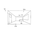
- FIG. 2 is explanatory drawing which shows typically the mode in the living room 101 in which the moving body detection unit 10 was installed.
- the moving body detection unit 10 is installed on the ceiling portion 101 a of each living room 101, and is communicably connected to the communication line 200.
- the living room 101 is a multi-bed room in which a plurality of beds 102 are installed, a plurality of moving body detection units 10 (corresponding to the number of beds 102) are installed corresponding to each bed 102.
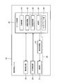
- FIG. 3 is a block diagram showing a schematic configuration of the moving body detection unit 10.
- the moving body detection unit 10 is a unit that detects information of a care recipient (subject) as a moving body in the living room 101, and includes an image recognition system 20, a radio wave detection unit 30, and a unit control unit 40.
- the motion detection unit 10 is also referred to as a sensor box because it includes various sensors such as the radio wave detection unit 30 and an optical detection unit 23 described later.
- the radio wave detection unit 30 is a sensor that detects the state of the care recipient in the living room 101 by radiation and reception of radio waves.
- the radio wave detection unit 30 includes a radiation unit and a reception unit (not shown), and for example, is a microwave Doppler sensor that radiates microwaves in the 24 GHz band and receives reflected waves that are reflected and Doppler-shifted by the care recipient Configured Accordingly, the radio wave detection unit 30 can detect the respiratory state, the sleep state, the heart rate, and the like of the care recipient from the received reflected wave as biological information.
- the radio wave detection unit 30 functions as a micro motion detection unit that detects micro motion of the care recipient (subject).
- the unit control unit 40 controls the operations of the image recognition system 20 and the radio wave detection unit 30, and performs image processing and signal processing on the information obtained from the image recognition system 20 and the radio wave detection unit 30. Is a control board that outputs the information to the management server 100a as information on the condition of the care recipient.
- the unit control unit 40 includes a main control unit 41, an information processing unit 42, an interface unit 43, a storage unit 24, and an image recognition unit 25.
- the storage unit 24 and the image recognition unit 25 are provided in the unit control unit 40 here, but may be provided independently of the unit control unit 40. The details of the storage unit 24 and the image recognition unit 25 will be described later.
- the main control unit 41 is configured of a CPU that controls the operation of each unit in the moving object detection unit 10.
- the information processing unit 42 and the image recognition unit 25 may be configured by the above-described CPU (may be integrated with the main control unit 41), or may be another calculation unit or a circuit that performs a specific process. It may be configured.
- the information processing unit 42 is configured to perform predetermined processing on information (for example, image data) output from an optical detection unit 23 described later of the image recognition system 20 and information (for example, data related to a breathing state) Perform signal processing based on the algorithm of The information obtained by the signal processing is used for image recognition in the image recognition system 20 (in particular, the image recognition unit 25).
- information for example, image data
- information for example, data related to a breathing state
- a network cable (not shown) of the communication line 200 is electrically connected to the interface unit 43.
- Information on the condition of the care receiver detected by the moving object detection unit 10 based on the image and the microwave is transmitted to the management server 100 a via the interface unit 43 and the communication line 200.
- the image recognition system 20 includes an illumination unit 21, an illumination control unit 22, and an optical detection unit 23.
- the lighting unit 21 includes an LED (Light Emitting Diode) that emits infrared light (for example, near infrared light) so as to enable photographing in the dark, and is positioned on the ceiling portion 101 a of the living room 101. , Illuminate the interior of the room 101.
- the illumination unit 21 includes a plurality of LEDs, and illuminates a floor surface 101b (see FIG. 2) in the living room 101 and a wall connecting the ceiling portion 101a and the floor surface 101b. Control of illumination (emission of infrared light) by the illumination unit 21 is performed by the illumination control unit 22.
- the optical detection unit 23 is an imaging unit that captures an image by capturing the inside of the living room 101 under the illumination of the illumination unit 21 and is configured by, for example, a camera.
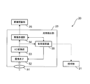
- FIG. 4 is a block diagram showing the detailed configuration of the optical detection unit 23.
- the optical detection unit 23 is disposed on the ceiling unit 101 a of the living room 101 adjacent to the illumination unit 21, and acquires an image of a viewpoint directly above, whose view direction is directly below, by photographing.
- the optical detection unit 23 includes a lens 51, an imaging device 52, an AD (analog / digital) conversion unit 53, an image processing unit 54, and a control calculation unit 55.
- the lens 51 is, for example, a fixed focus lens, and is configured of a general super wide-angle lens or a fisheye lens.
- a lens having a diagonal angle of view of 150 ° or more can be used. Thereby, it becomes possible to image the inside of the living room 101 from the ceiling portion 101a to the floor surface 101b.
- the imaging device 52 is configured of, for example, an image sensor such as a charge coupled device (CCD) or a complementary metal oxide semiconductor (CMOS).
- the imaging device 52 is configured by removing the IR cut filter so that the condition of the care recipient can be detected as an image even in a dark environment.
- An output signal from the imaging element 52 is input to the AD conversion unit 53.
- the AD conversion unit 53 receives an analog image signal of an image captured by the imaging element 52, and converts the analog image signal into a digital image signal.
- the digital image signal output from the AD conversion unit 53 is input to the image processing unit 54.
- the image processing unit 54 receives the digital image signal output from the AD conversion unit 53, and executes image processing such as black correction, noise correction, color interpolation, white balance, and the like on the digital image signal. .
- the signal after image processing output from the image processing unit 54 is input to the image recognition unit 25.
- the control calculation unit 55 performs calculations such as AE (Automatic Exposure) related to the control of the imaging device 52, and also controls the exposure time and gain of the imaging device 52. In addition, the control calculation unit 55 executes calculations such as suitable light amount setting and light distribution setting for the illumination unit 21 as necessary, and executes control.
- the control calculation unit 55 may have the function of the illumination control unit 22 described above.
- the above-described image recognition system 20 further includes the storage unit 24 and the image recognition unit 25 described above.
- the storage unit 24 is a memory for storing control programs executed by the unit control unit 40 and various types of information, and includes, for example, a random access memory (RAM), a read only memory (ROM), and a non-volatile memory.
- RAM random access memory
- ROM read only memory
- non-volatile memory non-volatile memory
- the image recognition unit 25 performs an image recognition process on the image data of the image acquired by the optical detection unit 23. More specifically, the image recognition unit 25 receives a signal after the image processing unit 54 of the optical detection unit 23 has performed the image processing, and extracts the contour of the object, for example, and performs shape matching by a method such as pattern matching. Execute image recognition processing to recognize Thereby, the image recognition unit 25 can recognize the state of the care receiver in the living room 101.
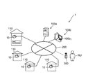
- FIG. 5 is an explanatory view showing a schematic configuration of the visit type care support system 1.
- the visit-type care support system 1 installs the above-described moving body detection unit 10 at each home (living room 110) of a subject who manages health, such as a carer or a carer, and each moving body detection unit 10 It is configured to be communicably connected to the management server 100a via the communication line 200, and the basic configuration is the same as the facility type care support system 1 except that the moving object detection unit 10 is installed in each building. It is.
- a user NU of the system owns (carries) a user terminal 300 capable of wireless communication with the management server 100 a via the communication line 200.
- the user NU can operate the user terminal 300 to access the management server 100a and acquire various information.
- a doctor, a care worker, or a nurse who visits a home of a target person such as a cared person and manages the health can be assumed.
- a multifunctional portable terminal such as a tablet or a smartphone, or a notebook personal computer can be assumed.
- FIG. 6 is a block diagram showing a schematic configuration of the information management system 60 of the present embodiment.
- the information management system 60 is a system applicable to the management server 100 a of both the facility type and the visit type care support system 1 described above, and includes the display unit 61, the operation unit 62, the database 63, the communication unit 64 and the like. , And a control unit 65.
- the display unit 61 is configured by, for example, a display (liquid crystal display device) of a personal computer, and displays various information.
- various information identification information, an attribute, etc. of a several subject are considered, for example.
- identification information of a plurality of target persons any information may be used as long as the target persons can be individually identified, such as a name, initials, a nickname, and a room number.
- attributes of a plurality of subjects for example, consider information (independent of the physical situation) that is not related to the physical condition, such as the age of the individual subject, the whereabouts, the number of years of use of the information management system 60 Can.
- the display unit 61 may be configured of a display unit with a touch panel.
- the operation unit 62 is operated by a user of the system (for example, a doctor, a caregiver, a nurse, a system administrator) to select a predetermined area on the display screen of the display unit 61 or to input predetermined information.
- a user of the system for example, a doctor, a caregiver, a nurse, a system administrator
- it comprises a keyboard and a mouse.
- the display unit 61 is configured of a display unit with a touch panel, the touch panel functions as the operation unit 62.
- the database 63 is configured by, for example, a hard disk, and stores health management information on medical care, care or nursing of individual subjects, and stores the information together with the above-mentioned attributes for each of a plurality of subjects (identification information). Part (memory).
- health management information for example, information such as the daily body temperature, respiratory rate (micromotion rate), blood pressure, and sleep state of the subject can be considered.
- the information to be detected by the moving body detection unit 10 for example, the respiratory rate, sleep state, bed rest state, absence state
- the information to be detected by the moving body detection unit 10 is the information output from the moving body detection unit 10 to the information management system 60 , And stored in the database 63 as health management information.
- the identification information and the attribute of the subject, and the information not to be detected by the moving body detection unit 10 are input by the operation of the operation unit 62 and health management It is stored in the database 63 as information.
- the information management system 60 may not have the database 63. That is, the database 63 may be provided outside the information management system 60, and the information management system 60 may access the database 63 to acquire the health management information.
- the communication unit 64 is an interface for inputting and outputting information between the information management system 60 and the outside, and includes a transmitting circuit, a receiving circuit, an antenna, and the like.
- the control unit 65 includes a display control unit 65a, an access control unit 65b, and an overall control unit 65c.
- the display control unit 65 a controls the display on the display unit 61.
- the access control unit 65b accesses the database 63 based on the operation by the operation unit 62, and acquires health management information of a predetermined target person.
- the overall control unit 65 c controls the operation of each unit of the information management system 60.
- the control unit 65 is configured of one CPU, and executes the functions of the display control unit 65a, the access control unit 65b, and the overall control unit 65c.
- the display control unit 65a, the access control unit 65b, and the overall control unit 65c may be configured by different CPUs.
- FIG. 7 is a flowchart showing the flow of processing in the information management system 60.
- processing of display of identification information (S1), selection of identification information (S2), acquisition of health management information (S3), and display of health management information (S4) is performed. The following will be described in order.
- S1 display of identification information
- individual identification information of a plurality of target persons to be managed is regularly arranged on the basis of the attribute of an individual unrelated to the physical condition and is combined with the attribute and displayed on the display unit 61. While being displayed, the individual identification information regularly arranged and displayed on the basis of the operation of the operation unit 62 is further displayed on the display unit 61 in a manner different according to the classification set in advance for the physical condition (display step).
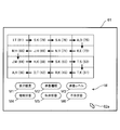
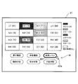
- FIG. 8 is an explanatory view showing an example of a display screen in the display unit 61.
- the identification information of the subject the initials of the subject (for example, if the surname is "patent" and the first name is " ⁇ .”, The initial is "IT") and the attribute of the subject is
- An example is shown in which the identification information of a plurality of subjects is sequentially arranged in a zigzag route from the upper left to the lower right in the two-dimensional matrix in ascending order of age using age.
- the numbers in parentheses in the figure indicate the age of the subject.
- the identification information of the subject is not arranged in the order of the Japanese syllabary (this point is apparent when looking at the order of the initials), but from the upper age to the lower right regularly Because you can see the display screen and search for a target person of a specific age, you can quickly and easily (and easily) display the display position of a specific age. The target person can be found quickly.
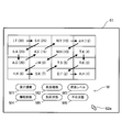
- FIG. 9 is an explanatory view showing another example of the display screen in the display unit 61.
- the identification information is arranged in order from the older one in the direction from the right to the screen left Thereafter, this may be alternately repeated to the lowermost stage of the screen (the fourth line in the example of FIG. 9).
- FIG. 10 is an explanatory view showing still another example of the display screen in the display unit 61.
- identification information May be arranged in order, and this may be alternately repeated up to the rightmost column (fourth column in the example of FIG. 10) on the screen.
- the identification information may be arranged in order of age from the left of the screen to the right of the screen in all the rows from the top of the screen to the bottom of the screen.
- the identification information may be arranged in order from the older one on the screen to the lower part of the screen in all the columns from the leftmost column on the screen to the rightmost column on the screen. Further, in the example described above, the identification information may be arranged in order from the smaller age.
- FIG. 11 is an explanatory view showing still another example of the display screen in the display unit 61.
- the age of usage of the information management system 60 is used as the attribute of the subject, and identification information of a plurality of subjects is sequentially from the upper left to the lower right in the two-dimensional matrix. You may arrange in order by the route of zigzag.
- the numbers in parentheses in the figure indicate the number of years of use of the subject.
- the identification information of the target person is regularly arranged from the upper left to the lower right sequentially from the one with many years of use of the system, it is specified when you want to look for the target person of specific use age by looking at the display screen You can quickly find the display position of the age of use, which allows you to quickly find the target person of a specific age of use.
- the physical condition selection mark M is displayed.
- the selection mark M is a situation selection for selecting each physical condition of “degree of need of care”, “type of disease”, “level of disease”, “sleeping state”, “bedbed state”, “absent state” It includes regions M1 to M6.
- the user of the system operates the operation unit 62 (for example, a mouse) to move the pointer 62a on the display screen and click at a predetermined position of the selection mark M (any of the situation selection areas M1 to M6 Can be instructed to display in a mode according to the selected physical condition.
- the display mode on the display unit 61 can be switched to the display mode according to the predetermined physical condition.
- the display control unit 65a can grasp the physical condition of each target person by referring to the database 63, the display control unit 65a displays the identification information of each target person in a mode according to the physical condition. It can be displayed on the part 61.
- each physical condition is classified into a plurality in advance.
- the degree of need of nursing care is classified into the degree of needed care 1 to 3 and the type of disease is classified into respiratory disease, circulatory disease, digestive disease and the like (eg, cancer (eg, cancer)
- the level of is classified into stages 1 to 4, the state of sleep is classified into sleep / wakening, the state of bed rest is classified into bed rest / wake up, and the state of absence is absent. / Classified as living room.
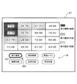
- each piece of identification information is displayed on the display unit 61 in a different manner according to the classification set in advance for the physical condition. For example, as shown in FIG.
- each identification information is displayed on the display unit 61 in a manner different depending on the degree of needed care of 1 to 3.
- the user of the system can quickly find a target person of a predetermined physical condition (target person belonging to a predetermined classification) by looking at the display unit 61.
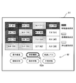
- 12 to 17 show different classifications by changing the type of hatching, but in addition, different classifications may be shown by changing the display color or the like.
- FIG. 18 shows a display example in the case where the identification information of a target person of a predetermined attribute (age) is selected by the operation unit 62 on the display screen of FIG.
- the user of the system operates the operation unit 62 to move the pointer 62a and clicks at the position of the identification information on the display screen, whereby the identification information can be selected.
- a target person of a predetermined physical condition is found from the display screen shown in FIG. 12 and the like (a display screen in which each identification information is displayed in a mode according to the physical condition)
- the identification information is selected.
- the identification information can be selected by the operation of the operation unit 62 similar to the above.
- S3 Acquisition of health management information, S4; display of health management information
- the access control unit 65b accesses the database 63, and the health management information of the target person corresponding to the selected identification information is displayed.
- the display control unit 65a causes the display unit 61 to display the health management information acquired by the access control unit 65b (S4; health management information display process).
- the display unit 61 functions as an output unit that outputs the health management information. Therefore, it can be said that the process of S4 is an output process which outputs the above-mentioned health management information.
- the health management information may be printed on paper by a printer instead of displaying the health management information on the display unit 61 in S4. In this case, the printer constitutes an output unit that outputs health management information.
- FIG. 19 shows a display example when the health management information of the subject corresponding to the identification information selected in FIG. 18 is displayed on the display unit 61 (The same layout is applied when the health management information is printed on paper. Is).
- the body temperature of the subject corresponding to the selected identification information, the movement speed (breathing rate), the blood pressure, and the information on the sleep state are displayed as health management information.
- an image (still image) captured by the moving body detection unit in the living room is also displayed together with the health management information.
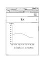
- FIG. 20 shows an example of a display screen when the column of body temperature is selected by the operation of the operation unit 62 on the display screen of FIG.
- the operation unit 62 By the above-described operation of the operation unit 62, a change in the temperature of the subject within a predetermined period in the past is displayed.
- the user of the system can look at the display screen and examine (understand) the health condition of the subject person in more detail.
- the age of individual subjects or the age of use of the system is used as the attribute of the individual.
- Age and age are attributes unrelated to the physical condition of the individual, and are stable information that does not change over a long period of time. Therefore, the user of the system can stably find out a specific target person for a long period of time from the regularly arranged attributes on the display unit 61.
- each identification information in a mode different depending on a preset classification, for each subject's degree of care required, type of disease, level of disease, sleep state, bed rest state, absent state Is displayed on the display unit 61 (see FIGS. 12 to 17).
- the user can easily find the target person of the predetermined classification from the identification information belonging to the predetermined classification regarding the degree of need of nursing care and the like.
- the display control unit 65a causes the display unit 61 to display the situation selection areas M1 to M6 for selecting any one of a plurality of physical situations, and causes the operation section 62 to select the situation selection area.
- the display control unit 65a causes the display unit 61 to display the situation selection areas M1 to M6 for selecting any one of a plurality of physical situations, and causes the operation section 62 to select the situation selection area.
- individual identification information is switched to a mode according to the physical condition corresponding to the selected condition selection area and displayed on the display unit 61 (FIG. 12 to FIG. 17).
- the health management information acquired in the access process of S3 is output (displayed) by the display unit 61 as an output unit. This enables the user of the system to strive for further health management of the subject based on the output (displayed) health management information.
- the management server 100a of the facility type or visit type care support system 1 is configured by the information management system 60 described above.
- the care support system 1 for example, even when looking for a cared person of a specific age or when looking for a cared person whose degree of required care belongs to a predetermined classification, the display screen of the display unit 61 is looked for You can easily find the care recipient you want. Then, the health management information on the found subject can be quickly acquired by accessing the database 63.
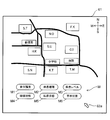
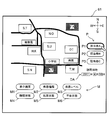
- FIG. 21 is an explanatory view showing still another example of the display screen in the display step of S1 described above.
- the display control unit 65a causes the display unit 61 to display individual identification information (for example, initials) superimposed on a map indicating the location, using the locations of the individual subjects as the attributes of the individual.
- individual identification information for example, initials
- a map indicating the location indicating the location
- users of the system such as a doctor who visits the subject's home often image individual subjects in a distinguishable manner at their locations. Therefore, the user can easily find the target person who is the object based on the whereabouts by displaying the individual identification information superimposed on the map indicating the whereabouts.
- displaying the identification information superimposed on the map showing the whereabouts means displaying the identification information at a position corresponding to the whereabouts on the map, which means that the identification information is displayed together with the whereabouts .
- FIG. 21 shows a display example in the case where the user of the system instructs, for example, display in a mode according to the degree of nursing care required by the operation of the operation unit 62 on the display screen shown in FIG.
- each identification information is displayed on the display unit 61 in a different manner depending on the degree of need for nursing care 1 to 3, the user of the system looks at the display unit 61 and quickly categorizes the target person who belongs to the classification of the degree of required care Can be found.
- the operation unit 62 instructs display in a mode according to a physical condition other than the degree of need for nursing care, the identification information is displayed in the same manner as in the case shown in FIGS. It is easy to find subjects who belong to the physical condition classification of.
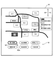
- FIG. 23 is explanatory drawing which shows the further another example of the display screen in the display process of S1.
- the identification information may be displayed at each matrix-like position by making the whereabouts of the object person (the position on the map) correspond to the simple two-dimensional matrix-like arrangement. . Even with such a display, the user of the system can easily find the subject corresponding to the predetermined location and the subject belonging to the predetermined physical condition classification.
- FIG. 24 is an explanatory view showing still another example of the display screen in the display step of S1 described above.
- the display control unit 65a is in charge of selecting persons in charge (for example, persons in charge A to C) who are in charge of medical care, care or nursing of each target person.
- the person selection area P (for example, P1 to P3) may be displayed on the display unit 61.
- the person-in-charge selection area P may be an area in which the names of the persons in charge can be freely input by the operation unit 62.
- the display control unit 65a displays the identification information of the target person in charge of the person in charge corresponding to the selected (inputted) person-in-charge selection area on the display unit 61 in a mode different from other identification information. You may
- FIG. 25 shows a display example when the person-in-charge selection area P1 is selected by the operation unit 62.
- identification information of a target person in charge of the person-in-charge A corresponding to the person-in-charge selection area P1 is hatched and displayed on the display unit 61.
- the identification information of the person in charge of the other persons in charge B and C may be displayed thin so that only the existence can be seen (the identification information can not be selected), or even if it is not displayed at all. Good.
- the person in charge A who is the user of the system can see the display unit 61 and immediately grasp the target person in charge of medical care and the like.
- FIG. 26 is an explanatory view showing still another example of the display screen in the display step of S1 described above.
- the display control unit 65a causes the date input box DA to be displayed on the display unit 61, and takes charge of the date of the input date when the date is input to the date input box DA by the operation unit 62.
- the identification information of the target person to be visited by the person may be displayed on the display unit 61 in a mode different from other identification information. Note that the (current) date of the day may be input in advance in the date input field DA by default.
- FIG. 27 shows a display example when the person-in-charge selection area P1 is selected by the operation unit 62 and the date is further input in the date input field DA.
- the identification information of the person who the person in charge A travels (visits) on the day of the date entered in the date input field DA is hatched. And displayed on the display unit 61.
- the identification information of the other target persons may be displayed thin so that only the existence can be known (the identification information can not be selected) or may not be displayed at all.
- the person in charge A who is the user of the system can see the display unit 61 and can immediately grasp the person to be visited on the day of the input date.
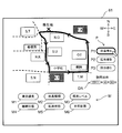
- FIG. 28 is an explanatory view showing still another example of the display screen in the display step of S1 described above.
- the display control unit 65a combines the traveling route (see thick line in the figure) of the person in charge traveling on the day of the input date with the map indicating the whereabouts of the object person in charge It may be displayed on the display unit 61. With such a display, the person in charge A can see the display portion 61 and can immediately confirm the whereabouts (visiting place) and the patrol route of the target person to be patrolled on the map at a glance, and patrol efficiently. Can.
- the above-mentioned patrol route may be set, for example, in the order of being able to turn preferentially from a subject requiring a high degree of care based on the classification of physical condition, or on the map in the order of turning from a subject close to the present location It may be set or may be set based on preset order information.
- the display modes shown in FIG. 24 to FIG. 28 can be used in combination with the display modes corresponding to the physical condition as shown in FIG.
- the left half of each piece of identification information shown in FIGS. 24 to 28 may be set as a display mode according to the physical condition.
- the person in charge A can visit the subject's home after confirming the physical condition (for example, the level of the degree of need of nursing care) of the subject to be patrolled by himself / herself and considering the response and measures in advance. .
- each identification information can be displayed on the map by setting transparency and displaying each identification information, or by pulling out one identification information from the position of the original location using a lead-out line, or the like. You should try not to overlap.
- the display shown in FIG. 21 to FIG. 28 may be performed by the management server 100 a of the facility type or visit type care support system 1, but in particular, it is necessary to visit the subject by relying on the residence. It is very effective in the visit type care support system 1. That is, by performing the display shown in FIG. 21 to FIG. 28 in the user terminal 300 owned by the user of the system, the user is the subject person in charge (subject person who needs patrol), the predetermined date It is possible to immediately grasp the person to be visited (visited) and the patrol route on the day of the day, which is extremely advantageous in performing patrol.
- the user terminal 300 may be configured by the information management system 60 described above.
- the database 63 is provided outside the user terminal 300 (for example, the management server 100a), and the user terminal 300 accesses the database 63 to acquire health management information.
- a program for causing the user terminal 300 (for example, CPU, computer) to execute each function of the information management system 60 from the server
- the program may be downloaded or installed in the user terminal 300 by reading the program from a recording medium (for example, a CD-ROM) in which the program is recorded.
- a recording medium for example, a CD-ROM
- the information management system described above includes a display unit, an operation unit for selecting a predetermined area on the display screen of the display unit, or for inputting predetermined information, and a plurality of target persons to be managed.
- the individual identification information is regularly arranged based on the attribute of the individual unrelated to the physical condition and displayed on the display unit together with the attribute, and regularly arranged and displayed based on the operation of the operation unit.
- a display control unit that causes the display unit to display the individual identification information in a manner that differs according to a classification previously set for the physical condition, and any identification information displayed on the display unit by the operation unit When selected, access to a database possessing health care information on medical care, care or nursing of the subject corresponding to the selected identification information, and the health And an access control unit for acquiring information.
- the display control unit displays the individual identification information (for example, name and initials) of the plurality of subjects regularly arranged and displayed based on the attribute (for example, age) of the individual unrelated to the physical condition. Displayed in the department.
- the individual identification information regularly displayed side by side by the operation of the operation unit further indicates the physical condition (for example, the degree of care required) Since the information is displayed on the display unit in a different manner according to the preset classification, it is possible to easily find the above-mentioned subject (subject belonging to the predetermined category) of the predetermined physical condition. In this way, when searching for a subject for different purposes, the subject can be easily found according to each purpose, so the health management information about the found subject can be accessed quickly by accessing the database. It becomes possible to acquire.
- the information management method described above regularly displays individual identification information of a plurality of target persons to be managed on the basis of the attribute of an individual unrelated to the physical condition, and displays the attribute and the attribute on the display unit.
- a database having health care information on medical care, care or nursing of the subject corresponding to the selected identification information is accessed.
- an access step of acquiring the health management information is acquired.
- the attribute may be either an age of an individual subject, a residence, or a use age of the system. Further, in the above information management method, the attribute may be either the age of an individual subject, the whereabouts, or the number of years of use of a system using the information management method.
- Age, etc. is an attribute of an individual unrelated to the physical condition, and is stable information that does not change over a long period, so from the regularly arranged attributes on the display unit, stable over a long period, a specific target person Can be found out.
- the attribute may be a residence of an individual subject, and the display control unit may display the identification information on the display unit so as to be superimposed on a map indicating the residence.
- the attribute may be a residence of an individual subject, and in the display step, the individual identification information may be displayed on the display unit while being superimposed on a map indicating the residence.
- Good For users of the system, individual subjects may be imaged at their location (differentiably). In such a case, it is possible to easily find the target person who is the object by superimposing the individual identification information on the map showing the whereabouts.
- the physical condition may be any of the care needs of individual subjects, types of diseases, levels of diseases, sleep states, bed rest states, absence states. In this case, it is possible to easily find a subject belonging to a predetermined classification from individual identification information displayed in a different manner according to the classification set in advance for the degree of nursing need etc.
- the display control unit causes the display unit to display a situation selection area for selecting any of a plurality of physical situations, and one of the situation selection areas is selected by the operation unit.
- the individual identification information may be switched to a mode according to the physical condition corresponding to the condition selection area and displayed on the display unit.
- a situation selection area for selecting any one of a plurality of physical situations is displayed on the display unit, and any one of the situation selection areas is selected by the operation unit.
- each of the identification information may be switched to a mode corresponding to the physical condition corresponding to the condition selection area and displayed on the display unit.
- the information management system may further include an output unit that outputs the health management information acquired by the access control unit.
- the information management method may further include the step of outputting the health management information acquired in the access step at an output unit.
- the display unit may double as the output unit, and the display control unit may cause the display unit to display the health management information acquired by the access control unit.
- the display unit doubles as the output unit, and the information management method includes a health management information display step of displaying the health management information acquired in the access step on the display portion. It may further be included.
- the display control unit causes the display unit to display a person-in-charge selection area for selecting a person in charge of medical care, care or nursing of each target person, and the operation control unit selects The identification information of the target person in charge of the person in charge corresponding to the selected person-in-charge selection area may be displayed on the display unit in a mode different from other identification information.
- a person-in-charge selection area for selecting a person in charge of medical care, care or nursing of each target person is displayed on the display unit, and the operation unit
- the identification information of the target person in charge of the person in charge corresponding to the selected person-in-charge selection area may be displayed on the display unit in a mode different from other identification information. In this case, the user (person in charge) of the system can see the display unit and immediately grasp the target person in charge of medical care and the like.
- the display control unit causes the display unit to display a date input field, and identification information of an object person who is to be patrolled by a person on the day of the date input to the date input field by the operation unit. May be displayed on the display unit in a manner different from other identification information.
- a date input field is displayed on the display unit, and identification of an object person who is to be patrolled by a person on the day of the date input in the date input field by the operation unit Information may be displayed on the display unit in a manner different from other identification information. In this case, the person in charge can view the display unit and immediately grasp the person who is to be patrolled on the day of the input date.
- the display control unit causes the display unit to display the traveling route of the person in charge traveling on the day of the input date, together with the map indicating the location of the person the person in charge travels.
- a traveling route of a person in charge traveling on a date of an input date is displayed on the display unit together with a map indicating the whereabouts of the object person who is traveling in the person in charge. You may In this case, the person in charge can see the display section and immediately grasp the whereabouts and the patrol route of the person to be patrolled, and can patrol efficiently.
- the care support system described above is a care support system that includes the above-described information management system and supports the life of each target person, and is installed in the room of each target person and the state of each target person And a management server that manages information output from the detection unit, and the management server may be configured by the information management system.
- the effects described above can be obtained in a care support system in which the information management system is applied to the management server.
- the care support system described above is a care support system that includes the above-described information management system and supports the life of each target person, and is installed in the room of each target person and the state of each target person And a user terminal capable of communicating with the management server, wherein the user terminal is configured by the information management system.
- the health management information may be acquired by accessing the external database. In this case, in the care support system in which the information management system is applied to the user terminal, the above-described effect can be obtained.
- the present invention is applicable to, for example, a system that manages information on the bodies of a plurality of subjects.
Landscapes
- Health & Medical Sciences (AREA)
- Public Health (AREA)
- Engineering & Computer Science (AREA)
- General Health & Medical Sciences (AREA)
- Medical Informatics (AREA)
- Primary Health Care (AREA)
- Epidemiology (AREA)
- General Business, Economics & Management (AREA)
- Biomedical Technology (AREA)
- Business, Economics & Management (AREA)
- Pathology (AREA)
- Nuclear Medicine, Radiotherapy & Molecular Imaging (AREA)
- Data Mining & Analysis (AREA)
- Databases & Information Systems (AREA)
- Radiology & Medical Imaging (AREA)
- Nursing (AREA)
- Life Sciences & Earth Sciences (AREA)
- Animal Behavior & Ethology (AREA)
- Veterinary Medicine (AREA)
- Accommodation For Nursing Or Treatment Tables (AREA)
- Medical Treatment And Welfare Office Work (AREA)
- Alarm Systems (AREA)
Abstract
情報管理システム(60)の表示制御部(65a)は、管理対象となる複数の対象者の個々の識別情報を、身体状況とは無関係な個人の属性に基づいて規則的に並べて属性と併せて表示部(61)に表示させるとともに、操作部(62)の操作に基づいて、規則的に並べて表示された個々の識別情報を、さらに身体状況について予め設定された分類によって異なる態様で表示部(61)に表示させる。アクセス制御部(65b)は、表示部(61)に表示されたいずれかの識別情報が操作部(62)によって選択されたときに、データベース(63)にアクセスして、選択された識別情報に対応する対象者の健康管理情報を取得する。
Description
本発明は、複数の対象者の身体に関する情報を管理する情報管理システムおよび情報管理方法と、上記情報管理システムを含むケアサポートシステムとに関するものである。
病院内のナースステーションでは、各病室内の患者の身体に関する情報が管理されており、患者の心拍数などをモニタ上で確認することができる。このようなナースステーションにおいて、モニタの表示を工夫するシステムが、例えば特許文献1に開示されている。特許文献1のシステムでは、入院患者からのナースコール子機による呼び出しに看護師が応答するためのナースコール親機が、ナースステーションに設置されている。そして、上記ナースコール親機が、入院患者の患者情報に含まれる少なくとも氏名およびベッド番号の一覧をカラー表示する表示部を有している。上記表示部では、病室ごとにフレームを設けてその内部に個々の患者情報を表示し、患者情報の一覧表示を実施するとともに、上記フレーム内の少なくとも一部を、男性部屋/女性部屋に応じて予め設定された色で表示する。これにより、表示部上で男性部屋/女性部屋を容易に判別することが可能となり、患者の誤配置を防止することが可能となる。
ところが、特許文献1のシステムでは、色分け表示によって部屋の種別の判断は容易になるものの、一覧表示における個々の患者の情報の並び方に規則性がない。このため、一覧表示から特定の患者(例えば1人)を探したい場合に、その患者を容易に(効率よく)見つけることができない。また、所定の身体状況の患者(例えばAという病気を患っている患者)を探したい場合でも、そのような患者(例えば複数人)の情報が他と区別できるように表示されないため、上記患者を容易に見つけることもできない。つまり、異なる目的で患者を探す場合のそれぞれにおいて、患者を表示情報から容易に見つけることができない。その結果、上記患者のさらに詳しい健康管理情報(日々の体温や呼吸数などの、健康を管理する上で必要な情報)を知りたい場合でも、そのような情報を有するデータベースに迅速にアクセスして、上記患者についての健康管理情報を迅速に取得することができない。
なお、このような問題は、例えば被介護者の日常生活を支援する目的で構築されるシステムにおいても同様に起こり得る。つまり、上記システムでは、被介護者が日常生活を営む居室内に、被介護者の状態(例えば起床/入床、転倒有無、呼吸)を検知する検知ユニットが設置され、各検知ユニットにて検知された情報が、管理サーバーに出力されてそこで管理される。このような管理サーバーの表示部において、一覧表示における被介護者の情報の並び方に規則性がなかったり、身体状況(例えば要介護度)に関係なく、被介護者の情報が同じ態様で表示されると、特定の被介護者を探す場合でも、所定の身体状況の被介護者(例えば要介護度が高い被介護者)を探す場合でも、そのような被介護者を一覧表示から容易に見つけることができない。その結果、上記被介護者の健康管理情報をデータベースから迅速に取得することができない。
本発明は、上記の問題点を解決するためになされたもので、その目的は、表示部に表示された情報に基づき、管理対象となる複数の対象者の中から、異なる目的で対象者を探す場合でも、それぞれの目的に応じて対象者を容易に(効率よく)見つけることができ、これによって、上記対象者の健康管理情報を、データベースにアクセスして迅速に取得することができる情報管理システム、情報管理方法およびケアサポートシステムを提供することにある。
本発明の一側面に係る情報管理システムは、表示部と、前記表示部の表示画面上での所定領域の選択、または所定情報の入力のための操作部と、管理対象となる複数の対象者の個々の識別情報を、身体状況とは無関係な個人の属性に基づいて規則的に並べて前記属性と併せて前記表示部に表示させるとともに、前記操作部の操作に基づいて、規則的に並べて表示された個々の前記識別情報を、さらに前記身体状況について予め設定された分類によって異なる態様で前記表示部に表示させる表示制御部と、前記表示部に表示されたいずれかの識別情報が前記操作部によって選択されたときに、選択された前記識別情報に対応する対象者の、医療、介護または看護に関する健康管理情報を所有するデータベースにアクセスして、前記健康管理情報を取得するアクセス制御部とを備えている。
本発明の他の側面に係る情報管理方法は、管理対象となる複数の対象者の個々の識別情報を、身体状況とは無関係な個人の属性に基づいて規則的に並べて前記属性と併せて表示部に表示するとともに、操作部の操作に基づいて、規則的に並べて表示された個々の前記識別情報を、さらに前記身体状況について予め設定された分類によって異なる態様で前記表示部に表示する表示工程と、前記表示部に表示されたいずれかの識別情報が前記操作部によって選択されたときに、選択された前記識別情報に対応する対象者の、医療、介護または看護に関する健康管理情報を所有するデータベースにアクセスして、前記健康管理情報を取得するアクセス工程とを含む。
本発明のさらに他の側面に係るケアサポートシステムは、上述した情報管理システムを含み、各々の対象者の生活を支援するケアサポートシステムであって、各々の対象者の居室に設置されて、各々の対象者の状態を検知する検知ユニットと、前記検知ユニットから出力される情報を管理する管理サーバーとを含み、前記管理サーバーが、前記情報管理システムで構成されている。
本発明のさらに他の側面に係るケアサポートシステムは、上述した情報管理システムを含み、各々の対象者の生活を支援するケアサポートシステムであって、各々の対象者の居室に設置されて、各々の対象者の状態を検知する検知ユニットと、前記検知ユニットから出力される情報を管理する管理サーバーと、前記管理サーバーと通信可能な利用者端末とを含み、前記利用者端末が、前記情報管理システムで構成され、外部の前記データベースにアクセスして、前記健康管理情報を取得する構成である。
表示部に表示された情報に基づき、管理対象となる複数の対象者の中から、異なる目的で対象者を探す場合でも、それぞれの目的に応じて対象者を容易に(効率よく)見つけることができる。これにより、見つけた上記対象者についての健康管理情報を、データベースにアクセスして迅速に取得することができる。
本発明の実施の一形態について、図面に基づいて説明すれば、以下の通りである。
本実施形態の情報管理システムは、介護施設に入居している被介護者や、病院に入院している患者(被看護者)の身体に関する情報の管理を目的として構築されるシステムである。また、上記情報管理システムは、本実施形態の情報管理方法を実現するシステムでもある。このような情報管理システムは、例えば施設型のケアサポートシステムの管理サーバーに適用可能であり、また、訪問型(訪問医療型、訪問介護型、訪問看護型を含む)のケアサポートシステムの管理サーバーや利用者端末にも適用可能である。以下、情報管理システムについて説明する前に、まず、施設型、訪問型の各ケアサポートシステムについて説明する。
〔ケアサポートシステム(施設型)〕
図1は、本実施形態の施設型のケアサポートシステム1の概略の構成を示す説明図である。ケアサポートシステム1は、介護施設に入居している被介護者や、病院に入院している患者(被看護者)の日常の生活を支援するためのシステムであり、見守りシステムとも呼ばれている。被介護者および被看護者は、ケアサポートシステム1による支援の対象、つまり、後述する画像認識システム20や電波検出部30での認識や検出等によって管理される対象者(被検者)である。ここでは、例として、ケアサポートシステム1が介護施設内で構築されている場合について説明する。
図1は、本実施形態の施設型のケアサポートシステム1の概略の構成を示す説明図である。ケアサポートシステム1は、介護施設に入居している被介護者や、病院に入院している患者(被看護者)の日常の生活を支援するためのシステムであり、見守りシステムとも呼ばれている。被介護者および被看護者は、ケアサポートシステム1による支援の対象、つまり、後述する画像認識システム20や電波検出部30での認識や検出等によって管理される対象者(被検者)である。ここでは、例として、ケアサポートシステム1が介護施設内で構築されている場合について説明する。
介護施設Sには、スタッフステーション100および居室101が設けられている。スタッフステーション100は、介護施設Sで過ごす被介護者の生活をサポートする介護者のいわゆる詰め所である。このスタッフステーション100には、管理サーバー100aが設けられている。管理サーバー100aは、通信回線200を介して、居室101に設置される後述の動体検知ユニット10と通信可能に接続される端末装置であり、中央演算処理装置(CPU;Central Processing Unit)を含んで構成される。なお、通信回線200は、例えば有線LAN(Local Area Network)で構成されるが、無線LANであっても勿論構わない。
管理サーバー100aは、通信回線200を介して、動体検知ユニット10から送信される各種の情報(例えば居室101内の撮影画像や被介護者の生体情報(例えば呼吸状態を示す情報))を受信して管理するとともに、受信した情報を表示部100b1に表示させる。これにより、介護施設Sの介護者やシステムの利用者は、表示部100b1に表示された情報を見て、被介護者の状態(呼吸状態、転倒有無など)を把握することができる。表示部100b1は、例えば管理サーバー100aと通信可能に接続されるパーソナルコンピュータ100bのディスプレイで構成することができる。なお、管理サーバー100aは、パーソナルコンピュータ100bと一体的に構成されてもよい。また、後述する画像認識システム20での画像認識処理により、被介護者が床面に転倒するなど、被介護者の動作が異常であることが認識されたときには、管理サーバー100aは、動体検知ユニット10からその旨の情報を受信して、動体検知ユニット10の光学検出部23で取得される居室101内の撮影画像のデータを、介護者が所有する携帯端末に送信し、被介護者の異常を介護者に知らせることも可能である。なお、動体検知ユニット10から管理サーバー100aへの画像データの送信時、および管理サーバー100aから上記携帯端末への画像データの送信時には、画像の容量、サイズ、解像度などが適宜調整される。
居室101は、介護施設Sにおいて少なくとも1つ設けられており、図1では例として居室101が2つ設けられている場合を示している。居室101内には、被介護者が使用するベッド102が1つ設置されている。なお、1つの居室101内に被介護者が二人以上入居する場合、被介護者の各々に対応して複数のベッド102が設置される。
図2は、動体検知ユニット10が設置された居室101内の様子を模式的に示す説明図である。図1および図2に示すように、動体検知ユニット10は、各居室101の天井部101aに設置され、通信回線200と通信可能に接続されている。居室101が複数のベッド102が設置された多床室である場合、動体検知ユニット10は、各ベッド102に対応して複数(各ベッド102の数だけ)設置される。
〔動体検知ユニット〕
次に、動体検知ユニット10について説明する。図3は、動体検知ユニット10の概略の構成を示すブロック図である。動体検知ユニット10は、居室101内の動体としての被介護者(被検者)の情報を検知するユニットであり、画像認識システム20、電波検出部30およびユニット制御部40を備えている。動体検知ユニット10は、電波検出部30をはじめ、後述する光学検出部23など、種々のセンサを備えていることから、センサボックスとも呼ばれる。
次に、動体検知ユニット10について説明する。図3は、動体検知ユニット10の概略の構成を示すブロック図である。動体検知ユニット10は、居室101内の動体としての被介護者(被検者)の情報を検知するユニットであり、画像認識システム20、電波検出部30およびユニット制御部40を備えている。動体検知ユニット10は、電波検出部30をはじめ、後述する光学検出部23など、種々のセンサを備えていることから、センサボックスとも呼ばれる。
電波検出部30は、電波の放射および受信によって、居室101内での被介護者の状態を検知するセンサである。電波検出部30は、不図示の放射部および受信部を備えており、例えば24GHz帯のマイクロ波を放射し、被介護者にて反射してドップラーシフトした反射波を受信するマイクロ波ドップラーセンサによって構成される。これにより、電波検出部30は、受信した反射波から被介護者の呼吸状態や睡眠状態、心拍数などを生体情報として検出することができる。
なお、被介護者が呼吸しているとき(睡眠中も含む)、被介護者の呼吸による体の微小な動き(微体動)が生じる。このため、被介護者の呼吸状態や睡眠状態を検出することは、被介護者の微体動を検出するのと同じである。このことから、電波検出部30は、被介護者(被検者)の微体動を検出する微体動検出部として機能しているとも言うことができる。
ユニット制御部40は、画像認識システム20および電波検出部30の動作を制御するとともに、画像認識システム20および電波検出部30から得た情報に対して画像処理や信号処理を行い、得られた結果を被介護者の状態に関する情報として管理サーバー100aに出力する制御基板である。
ユニット制御部40は、主制御部41、情報処理部42、インターフェース部43、記憶部24および画像認識部25を備えている。記憶部24および画像認識部25は、ここではユニット制御部40に設けられているが、ユニット制御部40とは独立して設けられていてもよい。なお、記憶部24および画像認識部25の詳細については後述する。
主制御部41は、動体検知ユニット10内の各部の動作を制御するCPUで構成されている。情報処理部42および画像認識部25は、上記のCPUで構成されてもよいし(主制御部41と一体化されていてもよいし)、他の演算部や、特定の処理を行う回路で構成されてもよい。
情報処理部42は、画像認識システム20の後述する光学検出部23から出力される情報(例えば画像データ)や、電波検出部30から出力される情報(例えば呼吸状態に関するデータ)に対して、所定のアルゴリズムに基づいた信号処理を行う。信号処理によって得られた情報は、画像認識システム20(特に画像認識部25)での画像認識に利用される。
インターフェース部43には、通信回線200のネットワークケーブル(不図示)が電気的に接続される。画像やマイクロ波に基づいて動体検知ユニット10が検出した被介護者の状態に関する情報は、インターフェース部43および通信回線200を介して管理サーバー100aに送信される。
画像認識システム20は、照明部21、照明制御部22および光学検出部23を備えている。
照明部21は、暗闇での撮影を可能にすべく、赤外線(例えば近赤外光)を発光するLED(Light Emitting Diode)を含んで構成されており、居室101の天井部101aに位置して、居室101内を照明する。例えば、照明部21は、複数のLEDを有しており、居室101内の床面101b(図2参照)や、天井部101aと床面101bとをつなぐ壁を照明する。照明部21による照明(赤外線の発光)の制御は、照明制御部22によって行われる。
光学検出部23は、照明部21の照明のもとで居室101内を撮影して画像を取得する撮像部であり、例えばカメラで構成される。図4は、光学検出部23の詳細な構成を示すブロック図である。光学検出部23は、居室101の天井部101aに、照明部21と隣接して配置されており、撮影によって視野方向が直下である直上視点の画像を取得する。この光学検出部23は、レンズ51、撮像素子52、AD(analog/digital)変換部53、画像処理部54および制御演算部55を備えている。
レンズ51は、例えば固定焦点レンズであり、一般的な超広角レンズや魚眼レンズで構成されている。超広角レンズとしては、対角画角が150°以上のレンズを用いることができる。これにより、天井部101aから床面101bに向かって居室101内を撮影することが可能となる。
撮像素子52は、例えばCCD(Charge Coupled Device)やCMOS(Complementary Metal Oxide Semiconductor)といったイメージセンサで構成されている。撮像素子52は、真っ暗な環境でも被介護者の状態が画像として検出できるように、IRカットフィルタを除去して構成されている。撮像素子52からの出力信号は、AD変換部53に入力される。
AD変換部53は、撮像素子52によって撮像された画像のアナログの画像信号を受信し、そのアナログの画像信号をデジタルの画像信号に変換する。AD変換部53から出力されるデジタルの画像信号は、画像処理部54に入力される。
画像処理部54は、AD変換部53から出力されるデジタルの画像信号を受信し、そのデジタルの画像信号に対して、例えば黒補正、ノイズ補正、色補間、ホワイトバランスなどの画像処理を実行する。画像処理部54から出力される画像処理後の信号は、画像認識部25に入力される。
制御演算部55は、撮像素子52の制御に関する例えばAE(Automatic Exposure)などの演算を実行するとともに、撮像素子52に対して露光時間やゲインなどの制御を実行する。また、制御演算部55は、必要に応じて、照明部21に対して好適な光量設定や配光設定などの演算を実行するとともに、制御を実行する。なお、制御演算部55に、上述の照明制御部22の機能を持たせるようにしてもよい。
上記した画像認識システム20は、さらに、上述した記憶部24および画像認識部25を備えている。
記憶部24は、ユニット制御部40が実行する制御プログラムや各種の情報を記憶するメモリであり、例えばRAM(Random Access Memory)、ROM(Read Only Memory)、不揮発性メモリなどで構成されている。
画像認識部25は、光学検出部23にて取得された画像の画像データに対して画像認識処理を行う。より具体的には、画像認識部25は、光学検出部23の画像処理部54が画像処理を実行した後の信号を受信し、例えば対象物の輪郭を抽出してパターンマッチング等の手法で形状を認識する画像認識処理を実行する。これにより、画像認識部25は、居室101内にいる被介護者の状態を認識することができる。
ここで、居室101内にいる被介護者の状態としては、起床、離床、入床(臥床)、転倒などが想定される。これらの被介護者の状態は、被介護者の体の大きさ動作(体動)を伴う点で、電波検出部30で検出される微体動(呼吸等による体の微小な動き)と区別される。
〔ケアサポートシステム(訪問型)〕
図5は、訪問型のケアサポートシステム1の概略の構成を示す説明図である。訪問型のケアサポートシステム1は、被介護者や被看護者などの健康を管理する対象者のそれぞれの自宅(居室110)に上述した動体検知ユニット10を設置し、各動体検知ユニット10を、通信回線200を介して管理サーバー100aと通信可能に接続して構成されており、建物ごとに動体検知ユニット10を設置した点を除けば、施設型のケアサポートシステム1と基本的な構成は同じである。
図5は、訪問型のケアサポートシステム1の概略の構成を示す説明図である。訪問型のケアサポートシステム1は、被介護者や被看護者などの健康を管理する対象者のそれぞれの自宅(居室110)に上述した動体検知ユニット10を設置し、各動体検知ユニット10を、通信回線200を介して管理サーバー100aと通信可能に接続して構成されており、建物ごとに動体検知ユニット10を設置した点を除けば、施設型のケアサポートシステム1と基本的な構成は同じである。
該システムの利用者NUは、管理サーバー100aと通信回線200を介して無線通信可能な利用者端末300を所有(携帯)している。これにより、利用者NUは、利用者端末300を操作して管理サーバー100aにアクセスし、種々の情報を取得することが可能である。なお、利用者NUとしては、被介護者などの対象者の自宅を訪問して健康を管理する医師、介護士、看護師を想定することができる。また、利用者端末300としては、タブレットやスマートフォンなどの多機能型携帯端末や、ノート型パーソナルコンピュータを想定することができる。
〔情報管理システム〕
次に、上述したケアサポートシステム1に適用可能な情報管理システムについて説明する。なお、以下では、身体に関する情報を管理する対象となる者、つまり、介護施設Sの各居室101に入居している被介護者、自宅(各居室110)で生活して訪問医療等を受ける被介護者や被看護者のことを、単に「対象者」とも称する。
次に、上述したケアサポートシステム1に適用可能な情報管理システムについて説明する。なお、以下では、身体に関する情報を管理する対象となる者、つまり、介護施設Sの各居室101に入居している被介護者、自宅(各居室110)で生活して訪問医療等を受ける被介護者や被看護者のことを、単に「対象者」とも称する。
図6は、本実施形態の情報管理システム60の概略の構成を示すブロック図である。情報管理システム60は、上述した施設型、訪問型の両方のケアサポートシステム1の管理サーバー100aに適用可能なシステムであり、表示部61と、操作部62と、データベース63と、通信部64と、制御部65とを備えている。
表示部61は、例えばパーソナルコンピュータのディスプレイ(液晶表示装置)で構成され、種々の情報を表示する。上記種々の情報としては、例えば、複数の対象者の識別情報や属性などが考えられる。ここで、複数の対象者の識別情報については、例えば氏名、イニシャル、ニックネーム、部屋番号など、対象者を個々に識別できる情報であれば何であってもよい。複数の対象者の属性としては、例えば個々の対象者の年齢、居所、情報管理システム60の利用年数(関わり累積時間)など、身体状況とは無関係な(身体状況に左右されない)情報を考えることができる。上記の身体状況とは、ここでは、例えば個々の対象者の要介護度、疾患の種類、疾患のレベル、睡眠状態、臥床状態、不在状態のいずれかを考えることができる。なお、表示部61は、タッチパネル付きの表示部で構成されてもよい。
操作部62は、表示部61の表示画面上での所定領域の選択、または所定情報の入力のためにシステムの利用者(例えば医師、介護士、看護師、システムの管理者)によって操作されるものであり、例えばキーボードやマウスによって構成される。なお、表示部61がタッチパネル付きの表示部で構成される場合、上記タッチパネルが操作部62として機能する。
データベース63は、例えばハードディスクで構成されており、個々の対象者の医療、介護または看護に関する健康管理情報を所有し、複数の対象者(識別情報)ごとに、上記した属性と併せて記憶する記憶部(メモリ)である。上記の健康管理情報としては、例えば、対象者の日々の体温、呼吸数(微体動数)、血圧、睡眠状態などの情報を考えることができる。健康管理情報の中で、動体検知ユニット10での検知対象である情報(例えば呼吸数、睡眠状態、臥床状態、不在状態)については、動体検知ユニット10から情報管理システム60に出力される情報が、健康管理情報としてデータベース63に記憶される。一方、対象者の識別情報および属性や、動体検知ユニット10での検知対象ではない情報(例えば要介護度、疾患の種類、疾患のレベル)については、操作部62の操作によって入力され、健康管理情報としてデータベース63に記憶される。
なお、情報管理システム60は、データベース63を有していなくてもよい。つまり、データベース63が情報管理システム60の外部に設けられて、情報管理システム60がデータベース63にアクセスして健康管理情報を取得する構成であってもよい。
通信部64は、情報管理システム60と外部との間で情報の入出力を行うためのインターフェースであり、送信回路、受信回路、アンテナなどを含んで構成される。
制御部65は、表示制御部65aと、アクセス制御部65bと、全体制御部65cとを含んでいる。表示制御部65aは、表示部61での表示を制御する。アクセス制御部65bは、操作部62による操作に基づき、データベース63にアクセスして、所定の対象者の健康管理情報を取得する。全体制御部65cは、情報管理システム60の各部の動作を制御する。制御部65は、1つのCPUで構成され、表示制御部65a、アクセス制御部65b、全体制御部65cの各機能を実行する。なお、表示制御部65a、アクセス制御部65b、全体制御部65cは、別々のCPUで構成されてもよい。
〔情報管理システムでの処理の流れ〕
次に、上記構成の情報管理システム60での処理について説明する。図7は、情報管理システム60における処理の流れを示すフローチャートである。情報管理システム60では、識別情報の表示(S1)、識別情報の選択(S2)、健康管理情報の取得(S3)、健康管理情報の表示(S4)の各処理が行われる。以下、順に説明する。
次に、上記構成の情報管理システム60での処理について説明する。図7は、情報管理システム60における処理の流れを示すフローチャートである。情報管理システム60では、識別情報の表示(S1)、識別情報の選択(S2)、健康管理情報の取得(S3)、健康管理情報の表示(S4)の各処理が行われる。以下、順に説明する。
(S1;識別情報の表示)
S1では、表示制御部65aの制御により、管理対象となる複数の対象者の個々の識別情報を、身体状況とは無関係な個人の属性に基づいて規則的に並べて属性と併せて表示部61に表示するとともに、操作部62の操作に基づいて、規則的に並べて表示された個々の識別情報を、さらに身体状況について予め設定された分類によって異なる態様で表示部61に表示する(表示工程)。
S1では、表示制御部65aの制御により、管理対象となる複数の対象者の個々の識別情報を、身体状況とは無関係な個人の属性に基づいて規則的に並べて属性と併せて表示部61に表示するとともに、操作部62の操作に基づいて、規則的に並べて表示された個々の識別情報を、さらに身体状況について予め設定された分類によって異なる態様で表示部61に表示する(表示工程)。
図8は、表示部61における表示画面の一例を示す説明図である。同図では、対象者の識別情報として対象者のイニシャル(例えば、姓が「特許」であり、名が「一朗」であれば、イニシャルは「I.T」)を用い、対象者の属性として年齢を用い、複数の対象者の識別情報を、年齢の大きいほうから順に、2次元マトリクス内の左上から右下に向かってジグザグの経路で順に並べた例を示している。なお、同図の括弧内の数字は、対象者の年齢を示している。この例では、対象者の識別情報は、五十音順には並んでいないが(この点はイニシャルの並びを見れば明らかである)、年齢の大きいほうから順に左上から右下に向かって規則的に並んでいるため、表示画面を見て特定の年齢の対象者を探したい場合に、特定の年齢の表示位置を素早く(容易に、効率よく)見つけることができ、これによって、特定の年齢の対象者を素早く見つけることができる。
なお、表示部61の表示画面上で複数の対象者の識別情報を規則的に並べるときの並べ方は、図8の例に限定されるわけではない。図9は、表示部61における表示画面の他の例を示す説明図である。同図のように、画面最上段の第1行において、画面左から画面右に向かい、次の第2行において、画面右から画面左に向かう方向に、年齢の大きいほうから識別情報を順に並べ、以下、これを画面最下段(図9の例では第4行)まで交互に繰り返すようにしてもよい。
図10は、表示部61における表示画面のさらに他の例を示す説明図である。同図のように、画面で最も左の第1列において、画面上から画面下に向かい、その右隣りの第2列において、画面下から画面上に向かう方向に、年齢の大きいほうから識別情報を順に並べ、以下、これを画面で最も右の列(図10の例では第4列)まで交互に繰り返すようにしてもよい。
なお、図示はしないが、画面最上段から画面最下段に向かって、全ての行において、画面左から画面右に、年齢の大きいほうから識別情報を順に並べてもよい。また、画面で最も左の列から画面で最も右の列に向かって、全ての列において、画面上から画面下に、年齢の大きいほうから識別情報を順に並べてもよい。また、以上で示した例において、年齢の小さいほうから順に識別情報を並べてもよい。
また、図11は、表示部61における表示画面のさらに他の例を示す説明図である。同図のように、対象者の属性として、情報管理システム60の利用年数を用い、複数の対象者の識別情報を、利用年数の多いほうから順に、2次元マトリクス内の左上から右下に向かってジグザグの経路で順に並べてもよい。なお、同図の括弧内の数字は、対象者の利用年数を示している。対象者の識別情報は、システムの利用年数の多いほうから順に左上から右下に向かって規則的に並んでいるため、表示画面を見て特定の利用年数の対象者を探したい場合に、特定の利用年数の表示位置を素早く見つけることができ、これによって、特定の利用年数の対象者を素早く見つけることができる。
図8~図11で示したいずれの表示画面においても、身体状況の選択マークMが表示されている。選択マークMは、それぞれ、「要介護度」、「疾患の種類」、「疾患のレベル」、「睡眠状態」、「臥床状態」、「不在状態」の各身体状況を選択するための状況選択領域M1~M6を含む。システムの利用者は、操作部62(例えばマウス)を操作して、表示画面上のポインタ62aを移動させ、選択マークMの所定の位置でクリックすることにより(状況選択領域M1~M6のいずれかを選択することにより)、選択した身体状況に応じた態様での表示を指示することができる。
図12~図17は、図8で示した表示画面において、システムの利用者が、操作部62の操作によって、異なる身体状況(要介護度、疾患の種類、疾患のレベル、睡眠状態、臥床状態、不在状態)に応じた態様での表示を指示した場合の表示例をそれぞれ示している。このように操作部62の操作により、表示部61での表示態様を、所定の身体状況に応じた表示態様に切り替えることができる。なお、個々の対象者の身体状況については、表示制御部65aがデータベース63を参照することで把握できるため、表示制御部65aは、個々の対象者の識別情報を身体状況に応じた態様で表示部61に表示させることができる。
また、個々の身体状況は、予め複数に分類されている。例えば、要介護度については、要介護度1~3に分類されており、疾患の種類については、呼吸器系疾患、循環器系疾患、消化器系疾患に分類されており、疾患(例えば癌)のレベルについては、ステージ1~4に分類されており、睡眠状態については、睡眠/覚醒に分類されており、臥床状態については、臥床/起床に分類されており、不在状態については、不在/在室に分類されている。図12~図17に示すように、表示制御部65aの制御により、個々の識別情報は、身体状況について予め設定された分類によって異なる態様で表示部61に表示される。例えば図12に示すように、要介護度に応じた表示態様が選択された場合、各識別情報は、要介護度1~3によって異なる態様で表示部61に表示される。これにより、システムの利用者は、表示部61を見て、所定の身体状況の対象者(所定の分類に属する対象者)を素早く見つけることができる。なお、図12~図17では、ハッチングの種類を変えることで異なる分類を示しているが、その他、表示色を変えるなどの方法で異なる分類を示してもよい。
(S2;識別情報の選択)
システムの利用者は、表示部61に表示された属性または身体状況に応じた表示を見て、目的となる対象者を見つけると、上記対象者に対応する識別情報を操作部62によって選択する(選択工程)。例えば、図18は、図8の表示画面において、所定の属性(年齢)の対象者の識別情報を操作部62によって選択する場合の表示例を示している。このように、システムの利用者が操作部62を操作してポインタ62aを移動させ、表示画面上の上記識別情報の位置でクリックすることにより、上記識別情報を選択することができる。なお、図12等で示した表示画面(各識別情報が身体状況に応じた態様で表示された表示画面)から、所定の身体状況の対象者を見つけてその識別情報を選択する場合でも、上記と同様の操作部62の操作により、上記識別情報を選択することができる。
システムの利用者は、表示部61に表示された属性または身体状況に応じた表示を見て、目的となる対象者を見つけると、上記対象者に対応する識別情報を操作部62によって選択する(選択工程)。例えば、図18は、図8の表示画面において、所定の属性(年齢)の対象者の識別情報を操作部62によって選択する場合の表示例を示している。このように、システムの利用者が操作部62を操作してポインタ62aを移動させ、表示画面上の上記識別情報の位置でクリックすることにより、上記識別情報を選択することができる。なお、図12等で示した表示画面(各識別情報が身体状況に応じた態様で表示された表示画面)から、所定の身体状況の対象者を見つけてその識別情報を選択する場合でも、上記と同様の操作部62の操作により、上記識別情報を選択することができる。
(S3;健康管理情報の取得、S4;健康管理情報の表示)
S2にて、目的となる対象者の識別情報が操作部62によって選択されると、アクセス制御部65bは、データベース63にアクセスして、選択された識別情報に対応する対象者の健康管理情報を取得する(S3;アクセス工程)。そして、表示制御部65aは、アクセス制御部65bによって取得された健康管理情報を表示部61に表示させる(S4;健康管理情報表示工程)。このとき、表示部61は、上記健康管理情報を出力する出力部として機能している。したがって、S4の工程は、上記健康管理情報を出力する出力工程であるとも言える。なお、S4にて、健康管理情報を表示部61にて表示する代わりに、健康管理情報をプリンタによって紙に印刷してもよい。この場合、プリンタが健康管理情報を出力する出力部を構成する。
S2にて、目的となる対象者の識別情報が操作部62によって選択されると、アクセス制御部65bは、データベース63にアクセスして、選択された識別情報に対応する対象者の健康管理情報を取得する(S3;アクセス工程)。そして、表示制御部65aは、アクセス制御部65bによって取得された健康管理情報を表示部61に表示させる(S4;健康管理情報表示工程)。このとき、表示部61は、上記健康管理情報を出力する出力部として機能している。したがって、S4の工程は、上記健康管理情報を出力する出力工程であるとも言える。なお、S4にて、健康管理情報を表示部61にて表示する代わりに、健康管理情報をプリンタによって紙に印刷してもよい。この場合、プリンタが健康管理情報を出力する出力部を構成する。
図19は、図18で選択した識別情報に対応する対象者の健康管理情報を表示部61に表示させたときの表示例を示している(健康管理情報を紙に印刷した場合も同様のレイアウトである)。この例では、選択した識別情報に対応する対象者の体温、微体動数(呼吸数)、血圧、睡眠状態に関する情報が、健康管理情報として表示されている。また、参考として、居室内の動体検知ユニットによって撮影された画像(静止画)も、上記健康管理情報と併せて表示されている。
図20は、図19の表示画面において、体温の欄を操作部62の操作によって選択したときの表示画面例を示している。操作部62の上記操作により、対象者の過去の所定期間内での体温の変化が表示される。これにより、システムの利用者は、表示画面を見て、対象者の健康状態をより詳しく調べる(把握する)ことが可能となる。
〔効果〕
以上のように、管理対象となる複数の対象者の個々の識別情報が、個人の属性に基づいて規則的に並べて表示部61に表示されるため、システムの利用者は、所定の属性を有する特定の対象者を探したい場合でも、その属性を表示画面上で容易に追うことが可能となり、特定の対象者を容易に見つけることができる。また、システムの利用者が所定の身体状況(例えば要介護度3)の対象者を探したい場合でも、操作部62の操作により、各識別情報が身体状況について予め設定された分類によって異なる態様で表示部61に表示されるため、表示画面上で上記対象者(要介護度3の対象者)を容易に見つけることができる。このように、異なる目的で対象者を探す場合でも、それぞれの目的に応じて対象者を容易に見つけることができるため、見つけた上記対象者についての健康管理情報を、データベース63にアクセスして迅速に取得することができる。
以上のように、管理対象となる複数の対象者の個々の識別情報が、個人の属性に基づいて規則的に並べて表示部61に表示されるため、システムの利用者は、所定の属性を有する特定の対象者を探したい場合でも、その属性を表示画面上で容易に追うことが可能となり、特定の対象者を容易に見つけることができる。また、システムの利用者が所定の身体状況(例えば要介護度3)の対象者を探したい場合でも、操作部62の操作により、各識別情報が身体状況について予め設定された分類によって異なる態様で表示部61に表示されるため、表示画面上で上記対象者(要介護度3の対象者)を容易に見つけることができる。このように、異なる目的で対象者を探す場合でも、それぞれの目的に応じて対象者を容易に見つけることができるため、見つけた上記対象者についての健康管理情報を、データベース63にアクセスして迅速に取得することができる。
また、以上では、個人の属性として、個々の対象者の年齢またはシステムの利用年数を用いている。年齢や利用年数は、個人の身体状況とは無関係な属性であり、長期にわたって変化しないステーブルな情報である。このため、システムの利用者は、表示部61上で規則的に並んだ属性から、長期にわたって安定して、特定の対象者を見つけ出すことができる。
また、上記身体状況として、個々の対象者の要介護度、疾患の種類、疾患のレベル、睡眠状態、臥床状態、不在状態のいずれについても、予め設定された分類によって異なる態様で、各識別情報が表示部61に表示される(図12~図17参照)。これにより、利用者は、要介護度等について所定の分類に属する識別情報から、所定の分類の対象者を容易に見つけることができる。
また、S1の表示工程において、表示制御部65aは、複数の身体状況の中からいずれかを選択するための状況選択領域M1~M6を表示部61に表示させるとともに、操作部62によって状況選択領域M1~M6のいずれかが選択されたときに、個々の識別情報を、選択された状況選択領域に対応する身体状況に応じた態様に切り替えて表示部61に表示させている(図12~図17参照)。これにより、身体状況の異なる表示態様に種々切り替えて、目的となる対象者を探すことが可能となる。
また、S4の健康管理情報表示工程では、S3のアクセス工程で取得した健康管理情報を、出力部としての表示部61にて出力(表示)させている。これにより、システムの利用者は、出力(表示)された健康管理情報に基づき、対象者のさらなる健康管理に努めることが可能となる。
また、施設型または訪問型のケアサポートシステム1の管理サーバー100aは、上述した情報管理システム60で構成される。この場合、ケアサポートシステム1において、例えば特定の年齢の被介護者を探す場合でも、要介護度が所定の分類に属する被介護者を探す場合でも、表示部61の表示画面を見て、探したい被介護者を容易に見つけることができる。そして、見つけた上記対象者についての健康管理情報を、データベース63にアクセスして迅速に取得することができる。
〔識別情報の他の表示例について〕
図21は、上述したS1の表示工程での表示画面のさらに他の例を示す説明図である。同図のように、個人の属性として、個々の対象者の居所を用い、表示制御部65aは、個々の識別情報(例えばイニシャル)を、居所を示す地図と重畳して表示部61に表示させてもよい。例えば、訪問型のケアサポートシステム1において、対象者の自宅を訪問する医師等のシステムの利用者は、個々の対象者を居所で区別可能にイメージしている場合が多い。そこで、個々の識別情報を、居所を示す地図上に重畳表示することにより、利用者は、目的となる対象者を、居所に基づいて容易に見つけることができる。なお、居所を示す地図と重畳して識別情報を表示するとは、地図上で居所と対応する位置に識別情報を表示することを指し、このことは居所とともに識別情報が表示されることを意味する。
図21は、上述したS1の表示工程での表示画面のさらに他の例を示す説明図である。同図のように、個人の属性として、個々の対象者の居所を用い、表示制御部65aは、個々の識別情報(例えばイニシャル)を、居所を示す地図と重畳して表示部61に表示させてもよい。例えば、訪問型のケアサポートシステム1において、対象者の自宅を訪問する医師等のシステムの利用者は、個々の対象者を居所で区別可能にイメージしている場合が多い。そこで、個々の識別情報を、居所を示す地図上に重畳表示することにより、利用者は、目的となる対象者を、居所に基づいて容易に見つけることができる。なお、居所を示す地図と重畳して識別情報を表示するとは、地図上で居所と対応する位置に識別情報を表示することを指し、このことは居所とともに識別情報が表示されることを意味する。
また、図21においても、表示部61の表示画面上に、身体状況の選択マークM(状況選択領域M1~M6)が表示される。これにより、システムの利用者は、操作部62を操作して表示画面上のポインタ62aを移動させ、状況選択領域M1~M6のいずれかを選択することにより、選択した身体状況に応じた態様での表示を指示することができる。図22は、図21で示した表示画面において、システムの利用者が、操作部62の操作によって、例えば要介護度に応じた態様での表示を指示した場合の表示例を示している。各識別情報は、要介護度1~3によって異なる態様で表示部61に表示されるため、システムの利用者は、表示部61を見て、所定の要介護度の分類に属する対象者を素早く見つけることができる。
なお、要介護度以外の身体状況に応じた態様での表示を操作部62によって指示した場合も、図13~図17で示した場合と同様の態様で各識別情報を表示することで、所定の身体状況の分類に属する対象者を容易に見つけることができる。
また、図23は、S1の表示工程での表示画面のさらに他の例を示す説明図である。対象者の居所に基づいて各識別情報を表示する場合、地図を表示することは必ずしも要しない。同図のように、対象者の居所(地図上での位置)を、簡略的な2次元のマトリクス状の配置に対応させて、マトリクス状の各位置に識別情報を表示するようにしてもよい。このような表示でも、システムの利用者は、所定の居所に対応する対象者、および所定の身体状況の分類に属する対象者を容易に見つけることができる。
なお、図21~図23のように識別情報を表示する場合であっても、S2以降の処理は上記と同様に行われる。したがって、図21~図23において、目的とする対象者の識別情報を操作部62の操作によって選択することにより、図19で示したような健康管理情報を表示部61に表示させることができる。
〔識別情報のさらに他の表示例について〕
図24は、上述したS1の表示工程での表示画面のさらに他の例を示す説明図である。同図のように、表示制御部65aは、図21の表示内容に加えて、各々の対象者の医療、介護または看護を担当する担当者(例えば担当者A~C)を選択するための担当者選択領域P(例えばP1~P3)を表示部61に表示させてもよい。なお、担当者選択領域Pは、操作部62によって各担当者の名前を自由に入力できる領域であってもよい。そして、表示制御部65aは、選択された(入力された)担当者選択領域に対応する担当者が担当する対象者の識別情報を、他の識別情報とは異なる態様で、表示部61に表示させてもよい。
図24は、上述したS1の表示工程での表示画面のさらに他の例を示す説明図である。同図のように、表示制御部65aは、図21の表示内容に加えて、各々の対象者の医療、介護または看護を担当する担当者(例えば担当者A~C)を選択するための担当者選択領域P(例えばP1~P3)を表示部61に表示させてもよい。なお、担当者選択領域Pは、操作部62によって各担当者の名前を自由に入力できる領域であってもよい。そして、表示制御部65aは、選択された(入力された)担当者選択領域に対応する担当者が担当する対象者の識別情報を、他の識別情報とは異なる態様で、表示部61に表示させてもよい。
図25は、操作部62によって担当者選択領域P1が選択されたときの表示例を示している。担当者選択領域P1が選択されると、担当者選択領域P1に対応する担当者Aが担当する対象者の識別情報が、ハッチングを付して表示部61に表示されている。このとき、他の担当者BおよびCが担当する対象者の識別情報については、存在だけがわかるように薄く表示されてもよいし(識別情報の選択はできなくなる)、全く表示されなくてもよい。これにより、システムの利用者である担当者Aは、表示部61を見て、自分が医療等を担当する対象者を即座に把握することができる。
図26は、上述したS1の表示工程での表示画面のさらに他の例を示す説明図である。同図のように、表示制御部65aは、日付入力欄DAを表示部61に表示させるとともに、操作部62によって日付入力欄DAに日付が入力されたときに、入力された日付の日に担当者が巡回する対象者の識別情報を、他の識別情報とは異なる態様で表示部61に表示させてもよい。なお、日付入力欄DAには、デフォルトでその日の(現在の)日付が予め入力されていてもよい。
図27は、操作部62によって担当者選択領域P1が選択され、さらに日付入力欄DAに日付が入力されたときの表示例を示している。担当者選択領域P1に対応する担当者Aが担当する対象者のうち、日付入力欄DAに入力された日付の日に担当者Aが巡回する(訪問する)対象者の識別情報が、ハッチングを付して表示部61に表示されている。このとき、他の対象者の識別情報については、存在だけがわかるように薄く表示されてもよいし(識別情報の選択はできなくなる)、全く表示されなくてもよい。これにより、システムの利用者である担当者Aは、表示部61を見て、入力された日付の日に自分が巡回する対象者を即座に把握することができる。
図28は、上述したS1の表示工程での表示画面のさらに他の例を示す説明図である。同図のように、表示制御部65aは、入力された日付の日に巡回する担当者の巡回ルート(図中の太線参照)を、担当者が巡回する対象者の居所を示す地図と併せて表示部61に表示させてもよい。このような表示により、担当者Aは、表示部61を見て、自分が巡回する対象者の居所(訪問場所)および巡回ルートを、地図上で一目で即座に確認でき、効率よく巡回することができる。なお、上記の巡回ルートは、例えば、身体状況の分類に基づき、要介護度の高い対象者から優先的に回れる順に設定されてもよいし、地図上で現在地から近い対象者から回れる順に設定されてもよいし、予め設定された順番情報に基づいて設定されてもよい。
なお、図24~図28で示した表示態様は、図22で示したような身体状況に応じた表示態様と併用することができる。例えば図24~図28で示した各識別情報の左半分を、身体状況に応じた表示態様とすればよい。この場合、担当者Aは、自分が巡回する対象者の身体状況(例えば要介護度のレベル)を確認し、その対応や措置を前もって考えた上で、対象者の自宅を訪問することができる。
なお、複数の対象者の居所が地図上で近く、地図上で各居所に対応する位置にそのまま各識別情報を表示させると、各識別情報が地図上で重なってしまう場合がある。そのような場合には、透明度を設定して各識別情報を表示したり、一方の識別情報を元の居所の位置から引き出し線を使って引き出して表示する、などによって各識別情報が地図上で重ならないようにすればよい。
以上の図21~図28で示した表示は、施設型または訪問型のケアサポートシステム1の管理サーバー100aにて行われてもよいが、特に、居所を頼りに対象者を訪問する必要がある訪問型のケアサポートシステム1において非常に有効である。つまり、システムの利用者が所有する利用者端末300において、図21~図28で示した表示を行うことにより、上記利用者が、担当の対象者(巡回が必要な対象者)、所定の日付の日に巡回(訪問)する対象者、巡回ルートをそれぞれ即座に把握することができ、巡回を行うにあたって非常に有利となる。利用者端末300において、図21~図28で示した表示を行うためには、利用者端末300が、上述した情報管理システム60で構成されていればよい。この場合、データベース63は利用者端末300の外部(例えば管理サーバー100a)に設けられ、利用者端末300からデータベース63にアクセスして健康管理情報を取得することになる。
なお、利用者端末300を情報管理システム60で構成するためには、情報管理システム60の各機能を利用者端末300(例えばCPU、コンピュータ)に実行させるためのプログラム(ソフトウェア、アプリケーション)をサーバーからダウンロードして、または、上記プログラムを記録した記録媒体(例えばCD-ROM)から上記プログラムを読み取って利用者端末300にインストールすればよい。これにより、利用者端末300を情報管理システム60として機能させることができる。
〔その他〕
以上で説明した本実施形態の情報管理システム、情報管理方法およびケアサポートシステムは、以下のように表現することができ、これによって以下の作用効果を奏すると言うことができる。
以上で説明した本実施形態の情報管理システム、情報管理方法およびケアサポートシステムは、以下のように表現することができ、これによって以下の作用効果を奏すると言うことができる。
すなわち、以上で説明した情報管理システムは、表示部と、前記表示部の表示画面上での所定領域の選択、または所定情報の入力のための操作部と、管理対象となる複数の対象者の個々の識別情報を、身体状況とは無関係な個人の属性に基づいて規則的に並べて前記属性と併せて前記表示部に表示させるとともに、前記操作部の操作に基づいて、規則的に並べて表示された個々の前記識別情報を、さらに前記身体状況について予め設定された分類によって異なる態様で前記表示部に表示させる表示制御部と、前記表示部に表示されたいずれかの識別情報が前記操作部によって選択されたときに、選択された前記識別情報に対応する対象者の、医療、介護または看護に関する健康管理情報を所有するデータベースにアクセスして、前記健康管理情報を取得するアクセス制御部とを備えている。
上記の構成によれば、表示制御部により、複数の対象者の個々の識別情報(例えば氏名やイニシャル)が、身体状況とは無関係な個人の属性(例えば年齢)に基づいて規則的に並べて表示部に表示される。これにより、表示部を見る者(例えばシステムの利用者)が、所定の属性を有する特定の対象者を探したい場合でも、表示部上で規則的に並んだ属性を順に追うことで、特定の対象者を容易に見つけることができる。また、表示部を見る者が所定の身体状況の対象者を探したい場合でも、操作部の操作により、規則的に並べて表示された個々の識別情報が、さらに身体状況(例えば要介護度)について予め設定された分類によって異なる態様で表示部に表示されるため、所定の身体状況の上記対象者(所定の分類に属する対象者)を容易に見つけることができる。このように、異なる目的で対象者を探す場合に、それぞれの目的に応じて対象者を容易に見つけることができるため、見つけた上記対象者についての健康管理情報を、データベースにアクセスして迅速に取得することが可能となる。
以上で説明した情報管理方法は、管理対象となる複数の対象者の個々の識別情報を、身体状況とは無関係な個人の属性に基づいて規則的に並べて前記属性と併せて表示部に表示するとともに、操作部の操作に基づいて、規則的に並べて表示された個々の前記識別情報を、さらに前記身体状況について予め設定された分類によって異なる態様で前記表示部に表示する表示工程と、前記表示部に表示されたいずれかの識別情報が前記操作部によって選択されたときに、選択された前記識別情報に対応する対象者の、医療、介護または看護に関する健康管理情報を所有するデータベースにアクセスして、前記健康管理情報を取得するアクセス工程とを含む。これにより、上記した情報管理システムによる効果と同様の効果を得ることができる。
上記情報管理システムにおいて、前記属性は、個々の対象者の年齢、居所、該システムの利用年数のいずれかであってもよい。また、上記情報管理方法において、前記属性は、個々の対象者の年齢、居所、該情報管理方法を使用するシステムの利用年数のいずれかであってもよい。年齢等は、身体状況とは無関係な個人の属性であり、長期にわたって変化しないステーブルな情報であるため、表示部上で規則的に並んだ属性から、長期にわたって安定して、特定の対象者を見つけ出すことができる。
上記情報管理システムにおいて、前記属性は、個々の対象者の居所であり、前記表示制御部は、個々の前記識別情報を、前記居所を示す地図と重畳して前記表示部に表示させてもよい。また、上記情報管理方法において、前記属性は、個々の対象者の居所であり、前記表示工程では、個々の前記識別情報を、前記居所を示す地図と重畳して前記表示部に表示してもよい。システムの利用者においては、個々の対象者が居所で(区別可能に)イメージされている場合がある。このような場合には、個々の識別情報を、居所を示す地図上に重畳表示することにより、目的となる対象者を容易に見つけることができる。
上記情報管理システムおよび上記情報管理方法において、前記身体状況は、個々の対象者の要介護度、疾患の種類、疾患のレベル、睡眠状態、臥床状態、不在状態のいずれかであってもよい。この場合、要介護度等について予め設定された分類によって異なる態様で表示される個々の識別情報から、所定の分類に属する対象者を容易に見つけることができる。
上記情報管理システムにおいて、前記表示制御部は、複数の身体状況の中からいずれかを選択するための状況選択領域を前記表示部に表示させるとともに、前記操作部によっていずれかの状況選択領域が選択されたときに、個々の前記識別情報を、前記状況選択領域に対応する身体状況に応じた態様に切り替えて前記表示部に表示させてもよい。また、上記情報管理方法において、前記表示工程では、複数の身体状況の中からいずれかを選択するための状況選択領域を前記表示部に表示するとともに、前記操作部によっていずれかの状況選択領域が選択されたときに、個々の前記識別情報を、前記状況選択領域に対応する身体状況に応じた態様に切り替えて前記表示部に表示してもよい。このような表示態様の切り替えにより、所望の身体状況に応じた表示態様を実現して、目的の対象者を探すことが可能となる。
上記情報管理システムは、前記アクセス制御部によって取得された前記健康管理情報を出力する出力部をさらに備えていてもよい。また、上記情報管理方法は、前記アクセス工程で取得した前記健康管理情報を、出力部にて出力する工程をさらに含んでいてもよい。取得した健康管理情報を出力部にて出力(表示または印刷)することにより、システムの利用者は、上記健康管理情報に基づき、対象者のさらなる健康管理に努めることが可能となる。
上記情報管理システムにおいて、前記表示部は、前記出力部を兼ねており、前記表示制御部は、前記アクセス制御部によって取得された前記健康管理情報を前記表示部に表示させてもよい。また、上記情報管理方法において、前記表示部は、前記出力部を兼ねており、該情報管理方法は、前記アクセス工程で取得した前記健康管理情報を前記表示部に表示する健康管理情報表示工程をさらに含んでいてもよい。取得した健康管理情報を表示部にて表示することにより、システムの利用者は、表示された上記健康管理情報に基づき、対象者のさらなる健康管理に努めることが可能となる。
上記情報管理システムにおいて、前記表示制御部は、各々の対象者の医療、介護または看護を担当する担当者を選択するための担当者選択領域を前記表示部に表示させるとともに、前記操作部によって選択された担当者選択領域に対応する担当者が担当する対象者の識別情報を、他の識別情報とは異なる態様で前記表示部に表示させてもよい。また、上記情報管理方法において、前記表示工程では、各々の対象者の医療、介護または看護を担当する担当者を選択するための担当者選択領域を前記表示部に表示するとともに、前記操作部によって選択された担当者選択領域に対応する担当者が担当する対象者の識別情報を、他の識別情報とは異なる態様で前記表示部に表示してもよい。この場合、システムの利用者(担当者)は、表示部を見て、自分が医療等を担当する対象者を即座に把握することができる。
上記情報管理システムにおいて、前記表示制御部は、日付入力欄を前記表示部に表示させるとともに、前記操作部によって前記日付入力欄に入力された日付の日に担当者が巡回する対象者の識別情報を、他の識別情報とは異なる態様で前記表示部に表示させてもよい。また、上記情報管理方法において、前記表示工程では、日付入力欄を前記表示部に表示するとともに、前記操作部によって前記日付入力欄に入力された日付の日に担当者が巡回する対象者の識別情報を、他の識別情報とは異なる態様で前記表示部に表示してもよい。この場合、担当者は、表示部を見て、入力された日付の日に自分が巡回する対象者を即座に把握することができる。
上記情報管理システムにおいて、前記表示制御部は、入力された日付の日に巡回する担当者の巡回ルートを、前記担当者が巡回する対象者の居所を示す地図と併せて前記表示部に表示させてもよい。また、上記情報管理方法において、前記表示工程では、入力された日付の日に巡回する担当者の巡回ルートを、前記担当者が巡回する対象者の居所を示す地図と併せて前記表示部に表示してもよい。この場合、担当者は、表示部を見て、自分が巡回する対象者の居所および巡回ルートを即座に把握して、効率よく巡回することができる。
以上で説明したケアサポートシステムは、上述した情報管理システムを含み、各々の対象者の生活を支援するケアサポートシステムであって、各々の対象者の居室に設置されて、各々の対象者の状態を検知する検知ユニットと、前記検知ユニットから出力される情報を管理する管理サーバーとを含み、前記管理サーバーが、前記情報管理システムで構成されていてもよい。この場合、管理サーバーに情報管理システムを適用したケアサポートシステムにおいて、上述の効果を得ることができる。
以上で説明したケアサポートシステムは、上述した情報管理システムを含み、各々の対象者の生活を支援するケアサポートシステムであって、各々の対象者の居室に設置されて、各々の対象者の状態を検知する検知ユニットと、前記検知ユニットから出力される情報を管理する管理サーバーと、前記管理サーバーと通信可能な利用者端末とを含み、前記利用者端末が、前記情報管理システムで構成され、外部の前記データベースにアクセスして、前記健康管理情報を取得する構成であってもよい。この場合、利用者端末に情報管理システムを適用したケアサポートシステムにおいて、上述の効果を得ることができる。
以上、本発明の実施形態につき説明したが、本発明の範囲はこれに限定されるものではなく、発明の主旨を逸脱しない範囲で種々の変更を加えて実施することができる。
本発明は、例えば複数の対象者の身体に関する情報を管理するシステムに利用可能である。
1 ケアサポートシステム
10 動体検知ユニット(検知ユニット)
60 情報管理システム
61 表示部(出力部)
62 操作部
63 データベース
65a 表示制御部
65b アクセス制御部
100a 管理サーバー
300 利用者端末
10 動体検知ユニット(検知ユニット)
60 情報管理システム
61 表示部(出力部)
62 操作部
63 データベース
65a 表示制御部
65b アクセス制御部
100a 管理サーバー
300 利用者端末
Claims (22)
- 表示部と、
前記表示部の表示画面上での所定領域の選択、または所定情報の入力のための操作部と、
管理対象となる複数の対象者の個々の識別情報を、身体状況とは無関係な個人の属性に基づいて規則的に並べて前記属性と併せて前記表示部に表示させるとともに、前記操作部の操作に基づいて、規則的に並べて表示された個々の前記識別情報を、さらに前記身体状況について予め設定された分類によって異なる態様で前記表示部に表示させる表示制御部と、
前記表示部に表示されたいずれかの識別情報が前記操作部によって選択されたときに、選択された前記識別情報に対応する対象者の、医療、介護または看護に関する健康管理情報を所有するデータベースにアクセスして、前記健康管理情報を取得するアクセス制御部とを備えている、情報管理システム。 - 前記属性は、個々の対象者の年齢、居所、該システムの利用年数のいずれかである、請求項1に記載の情報管理システム。
- 前記属性は、個々の対象者の居所であり、
前記表示制御部は、個々の前記識別情報を、前記居所を示す地図と重畳して前記表示部に表示させる、請求項1に記載の情報管理システム。 - 前記身体状況は、個々の対象者の要介護度、疾患の種類、疾患のレベル、睡眠状態、臥床状態、不在状態のいずれかである、請求項1から3のいずれかに記載の情報管理システム。
- 前記表示制御部は、複数の身体状況の中からいずれかを選択するための状況選択領域を前記表示部に表示させ、前記操作部によっていずれかの状況選択領域が選択されたときに、個々の前記識別情報を、前記状況選択領域に対応する身体状況に応じた態様に切り替えて前記表示部に表示させる、請求項1から4のいずれかに記載の情報管理システム。
- 前記アクセス制御部によって取得された前記健康管理情報を出力する出力部をさらに備えている、請求項5に記載の情報管理システム。
- 前記表示部は、前記出力部を兼ねており、
前記表示制御部は、前記アクセス制御部によって取得された前記健康管理情報を前記表示部に表示させる、請求項6に記載の情報管理システム。 - 前記表示制御部は、各々の対象者の医療、介護または看護を担当する担当者を選択するための担当者選択領域を前記表示部に表示させるとともに、前記操作部によって選択された担当者選択領域に対応する担当者が担当する対象者の識別情報を、他の識別情報とは異なる態様で前記表示部に表示させる、請求項1から7のいずれかに記載の情報管理システム。
- 前記表示制御部は、日付入力欄を前記表示部に表示させるとともに、前記操作部によって前記日付入力欄に入力された日付の日に担当者が巡回する対象者の識別情報を、他の識別情報とは異なる態様で前記表示部に表示させる、請求項8に記載の情報管理システム。
- 前記表示制御部は、入力された日付の日に巡回する担当者の巡回ルートを、前記担当者が巡回する対象者の居所を示す地図と併せて前記表示部に表示させる、請求項9に記載の情報管理システム。
- 請求項1から10のいずれかに記載の情報管理システムを含み、各々の対象者の生活を支援するケアサポートシステムであって、
各々の対象者の居室に設置されて、各々の対象者の状態を検知する検知ユニットと、
前記検知ユニットから出力される情報を管理する管理サーバーとを含み、
前記管理サーバーが、前記情報管理システムで構成されていることを特徴とするケアサポートシステム。 - 請求項1から10のいずれかに記載の情報管理システムを含み、各々の対象者の生活を支援するケアサポートシステムであって、
各々の対象者の居室に設置されて、各々の対象者の状態を検知する検知ユニットと、
前記検知ユニットから出力される情報を管理する管理サーバーと、
前記管理サーバーと通信可能な利用者端末とを含み、
前記利用者端末が、前記情報管理システムで構成され、外部の前記データベースにアクセスして、前記健康管理情報を取得することを特徴とするケアサポートシステム。 - 管理対象となる複数の対象者の個々の識別情報を、身体状況とは無関係な個人の属性に基づいて規則的に並べて前記属性と併せて表示部に表示するとともに、操作部の操作に基づいて、規則的に並べて表示された個々の前記識別情報を、さらに前記身体状況について予め設定された分類によって異なる態様で前記表示部に表示する表示工程と、
前記表示部に表示されたいずれかの識別情報が前記操作部によって選択されたときに、選択された前記識別情報に対応する対象者の、医療、介護または看護に関する健康管理情報を所有するデータベースにアクセスして、前記健康管理情報を取得するアクセス工程とを含むことを特徴とする情報管理方法。 - 前記属性は、個々の対象者の年齢、居所、該情報管理方法を使用するシステムの利用年数のいずれかである、請求項13に記載の情報管理方法。
- 前記属性は、個々の対象者の居所であり、
前記表示工程では、個々の前記識別情報を、前記居所を示す地図と重畳して前記表示部に表示する、請求項13に記載の情報管理方法。 - 前記身体状況は、個々の対象者の要介護度、疾患の種類、疾患のレベル、睡眠状態、臥床状態、不在状態のいずれかである、請求項13から15のいずれかに記載の情報管理方法。
- 前記表示工程では、複数の身体状況の中からいずれかを選択するための状況選択領域を前記表示部に表示するとともに、前記操作部によっていずれかの状況選択領域が選択されたときに、個々の前記識別情報を、前記状況選択領域に対応する身体状況に応じた態様に切り替えて前記表示部に表示する、請求項13から16のいずれかに記載の情報管理方法。
- 前記アクセス工程で取得した前記健康管理情報を、出力部にて出力する工程をさらに含む、請求項17に記載の情報管理方法。
- 前記表示部は、前記出力部を兼ねており、
該情報管理方法は、前記アクセス工程で取得した前記健康管理情報を前記表示部に表示する健康管理情報表示工程をさらに含む、請求項18に記載の情報管理方法。 - 前記表示工程では、各々の対象者の医療、介護または看護を担当する担当者を選択するための担当者選択領域を前記表示部に表示するとともに、前記操作部によって選択された担当者選択領域に対応する担当者が担当する対象者の識別情報を、他の識別情報とは異なる態様で前記表示部に表示する、請求項13から19のいずれかに記載の情報管理方法。
- 前記表示工程では、日付入力欄を前記表示部に表示するとともに、前記操作部によって前記日付入力欄に入力された日付の日に担当者が巡回する対象者の識別情報を、他の識別情報とは異なる態様で前記表示部に表示する、請求項20に記載の情報管理方法。
- 前記表示工程では、入力された日付の日に巡回する担当者の巡回ルートを、前記担当者が巡回する対象者の居所を示す地図と併せて前記表示部に表示する、請求項21に記載の情報管理方法。
Priority Applications (1)
| Application Number | Priority Date | Filing Date | Title |
|---|---|---|---|
| JP2019537991A JP7247889B2 (ja) | 2017-08-22 | 2018-07-19 | 情報管理システム、情報管理方法およびケアサポートシステム |
Applications Claiming Priority (2)
| Application Number | Priority Date | Filing Date | Title |
|---|---|---|---|
| JP2017-159265 | 2017-08-22 | ||
| JP2017159265 | 2017-08-22 |
Publications (1)
| Publication Number | Publication Date |
|---|---|
| WO2019039145A1 true WO2019039145A1 (ja) | 2019-02-28 |
Family
ID=65438624
Family Applications (1)
| Application Number | Title | Priority Date | Filing Date |
|---|---|---|---|
| PCT/JP2018/027071 Ceased WO2019039145A1 (ja) | 2017-08-22 | 2018-07-19 | 情報管理システム、情報管理方法およびケアサポートシステム |
Country Status (2)
| Country | Link |
|---|---|
| JP (1) | JP7247889B2 (ja) |
| WO (1) | WO2019039145A1 (ja) |
Cited By (1)
| Publication number | Priority date | Publication date | Assignee | Title |
|---|---|---|---|---|
| JP2020194493A (ja) * | 2019-05-30 | 2020-12-03 | アースアイズ株式会社 | 介護設備又は病院用の監視システム及び監視方法 |
Citations (6)
| Publication number | Priority date | Publication date | Assignee | Title |
|---|---|---|---|---|
| JP2005244581A (ja) * | 2004-02-26 | 2005-09-08 | Keakomu:Kk | ナースコール親機 |
| JP5158548B2 (ja) * | 2009-01-29 | 2013-03-06 | 株式会社在宅医療システム研究所 | 在宅医療支援システム |
| JP2015191526A (ja) * | 2014-03-28 | 2015-11-02 | エコナビスタ株式会社 | 情報処理装置、プログラム、情報処理システム及び情報表示方法 |
| JP2015188492A (ja) * | 2014-03-27 | 2015-11-02 | アイホン株式会社 | ナースコールシステム |
| JP2016057979A (ja) * | 2014-09-11 | 2016-04-21 | エコナビスタ株式会社 | 情報処理装置、プログラム及び情報処理方法 |
| JP6172424B1 (ja) * | 2016-02-24 | 2017-08-02 | コニカミノルタ株式会社 | 端末装置および端末装置の制御方法ならびに被監視者監視システム |
Family Cites Families (1)
| Publication number | Priority date | Publication date | Assignee | Title |
|---|---|---|---|---|
| JP6315911B2 (ja) * | 2013-07-09 | 2018-04-25 | キヤノン株式会社 | 画像符号化装置、画像符号化方法及びプログラム、画像復号装置、画像復号方法及びプログラム |
-
2018
- 2018-07-19 JP JP2019537991A patent/JP7247889B2/ja active Active
- 2018-07-19 WO PCT/JP2018/027071 patent/WO2019039145A1/ja not_active Ceased
Patent Citations (6)
| Publication number | Priority date | Publication date | Assignee | Title |
|---|---|---|---|---|
| JP2005244581A (ja) * | 2004-02-26 | 2005-09-08 | Keakomu:Kk | ナースコール親機 |
| JP5158548B2 (ja) * | 2009-01-29 | 2013-03-06 | 株式会社在宅医療システム研究所 | 在宅医療支援システム |
| JP2015188492A (ja) * | 2014-03-27 | 2015-11-02 | アイホン株式会社 | ナースコールシステム |
| JP2015191526A (ja) * | 2014-03-28 | 2015-11-02 | エコナビスタ株式会社 | 情報処理装置、プログラム、情報処理システム及び情報表示方法 |
| JP2016057979A (ja) * | 2014-09-11 | 2016-04-21 | エコナビスタ株式会社 | 情報処理装置、プログラム及び情報処理方法 |
| JP6172424B1 (ja) * | 2016-02-24 | 2017-08-02 | コニカミノルタ株式会社 | 端末装置および端末装置の制御方法ならびに被監視者監視システム |
Cited By (1)
| Publication number | Priority date | Publication date | Assignee | Title |
|---|---|---|---|---|
| JP2020194493A (ja) * | 2019-05-30 | 2020-12-03 | アースアイズ株式会社 | 介護設備又は病院用の監視システム及び監視方法 |
Also Published As
| Publication number | Publication date |
|---|---|
| JP7247889B2 (ja) | 2023-03-29 |
| JPWO2019039145A1 (ja) | 2020-07-30 |
Similar Documents
| Publication | Publication Date | Title |
|---|---|---|
| Virone et al. | An advanced wireless sensor network for health monitoring | |
| US20180374570A1 (en) | Central processing device and central processing method for subject observation system and subject observation system | |
| JP2019030628A (ja) | 情報提供装置、情報提供システム、情報提供方法、及びプログラム | |
| JP2020071503A (ja) | ケアシステム、その管理方法、およびプログラム | |
| Esch | A survey on ambient intelligence in healthcare | |
| JP7226315B2 (ja) | ケアサポートシステムおよび情報通知制御方法 | |
| JP7120238B2 (ja) | 発報制御システム、検知ユニット、ケアサポートシステムおよび発報制御方法 | |
| JP7180597B2 (ja) | 発報制御システム、検知ユニット、ケアサポートシステムおよび発報制御方法 | |
| JP2008289676A (ja) | 患者異常通知システム | |
| JP7247889B2 (ja) | 情報管理システム、情報管理方法およびケアサポートシステム | |
| JP7480475B2 (ja) | 通知制御システム、通知制御方法、及びプログラム | |
| KR20050090947A (ko) | 실버텔 운영 시스템 | |
| WO2020075675A1 (ja) | ケアシステムの管理方法および管理装置、ならびにプログラム | |
| WO2020009107A1 (ja) | 情報処理装置、センサーボックス、および、プログラム | |
| JPWO2020003735A1 (ja) | ケアサポートシステムおよび情報提供方法 | |
| JP7327389B2 (ja) | ケアサポートシステム及び情報処理方法 | |
| JP2020194392A (ja) | 情報を通知するためのプログラム、情報通知装置、および、情報を通知するためにコンピューターで実行される方法 | |
| JP2023177885A (ja) | 情報処理装置、情報処理システム、および、情報処理方法 | |
| JP7380551B2 (ja) | ケアサポートシステム及び情報処理方法 | |
| JP2020129214A (ja) | 見守り装置および見守りプログラム | |
| JP7840298B2 (ja) | 情報処理システム及び制御方法 | |
| JP2019194764A (ja) | ケアサポートシステム | |
| WO2020075674A1 (ja) | ケアシステムの管理方法および管理装置、ならびにプログラム | |
| JP7163923B2 (ja) | ケアサポートシステムおよび通信制御方法 | |
| JPWO2019216063A1 (ja) | ケアサポートシステムおよび情報提供方法 |
Legal Events
| Date | Code | Title | Description |
|---|---|---|---|
| 121 | Ep: the epo has been informed by wipo that ep was designated in this application |
Ref document number: 18847627 Country of ref document: EP Kind code of ref document: A1 |
|
| ENP | Entry into the national phase |
Ref document number: 2019537991 Country of ref document: JP Kind code of ref document: A |
|
| NENP | Non-entry into the national phase |
Ref country code: DE |
|
| 122 | Ep: pct application non-entry in european phase |
Ref document number: 18847627 Country of ref document: EP Kind code of ref document: A1 |