WO2019035172A1 - Système de source d'alimentation pour véhicule - Google Patents
Système de source d'alimentation pour véhicule Download PDFInfo
- Publication number
- WO2019035172A1 WO2019035172A1 PCT/JP2017/029319 JP2017029319W WO2019035172A1 WO 2019035172 A1 WO2019035172 A1 WO 2019035172A1 JP 2017029319 W JP2017029319 W JP 2017029319W WO 2019035172 A1 WO2019035172 A1 WO 2019035172A1
- Authority
- WO
- WIPO (PCT)
- Prior art keywords
- fuel cell
- sofc
- voltage
- vehicle power
- controller
- Prior art date
Links
Images


Classifications
-
- H—ELECTRICITY
- H01—ELECTRIC ELEMENTS
- H01M—PROCESSES OR MEANS, e.g. BATTERIES, FOR THE DIRECT CONVERSION OF CHEMICAL ENERGY INTO ELECTRICAL ENERGY
- H01M8/00—Fuel cells; Manufacture thereof
- H01M8/04—Auxiliary arrangements, e.g. for control of pressure or for circulation of fluids
- H01M8/04298—Processes for controlling fuel cells or fuel cell systems
- H01M8/04694—Processes for controlling fuel cells or fuel cell systems characterised by variables to be controlled
- H01M8/04858—Electric variables
- H01M8/04865—Voltage
- H01M8/04888—Voltage of auxiliary devices, e.g. batteries, capacitors
-
- B—PERFORMING OPERATIONS; TRANSPORTING
- B60—VEHICLES IN GENERAL
- B60L—PROPULSION OF ELECTRICALLY-PROPELLED VEHICLES; SUPPLYING ELECTRIC POWER FOR AUXILIARY EQUIPMENT OF ELECTRICALLY-PROPELLED VEHICLES; ELECTRODYNAMIC BRAKE SYSTEMS FOR VEHICLES IN GENERAL; MAGNETIC SUSPENSION OR LEVITATION FOR VEHICLES; MONITORING OPERATING VARIABLES OF ELECTRICALLY-PROPELLED VEHICLES; ELECTRIC SAFETY DEVICES FOR ELECTRICALLY-PROPELLED VEHICLES
- B60L1/00—Supplying electric power to auxiliary equipment of vehicles
-
- B—PERFORMING OPERATIONS; TRANSPORTING
- B60—VEHICLES IN GENERAL
- B60L—PROPULSION OF ELECTRICALLY-PROPELLED VEHICLES; SUPPLYING ELECTRIC POWER FOR AUXILIARY EQUIPMENT OF ELECTRICALLY-PROPELLED VEHICLES; ELECTRODYNAMIC BRAKE SYSTEMS FOR VEHICLES IN GENERAL; MAGNETIC SUSPENSION OR LEVITATION FOR VEHICLES; MONITORING OPERATING VARIABLES OF ELECTRICALLY-PROPELLED VEHICLES; ELECTRIC SAFETY DEVICES FOR ELECTRICALLY-PROPELLED VEHICLES
- B60L15/00—Methods, circuits, or devices for controlling the traction-motor speed of electrically-propelled vehicles
- B60L15/007—Physical arrangements or structures of drive train converters specially adapted for the propulsion motors of electric vehicles
-
- B—PERFORMING OPERATIONS; TRANSPORTING
- B60—VEHICLES IN GENERAL
- B60L—PROPULSION OF ELECTRICALLY-PROPELLED VEHICLES; SUPPLYING ELECTRIC POWER FOR AUXILIARY EQUIPMENT OF ELECTRICALLY-PROPELLED VEHICLES; ELECTRODYNAMIC BRAKE SYSTEMS FOR VEHICLES IN GENERAL; MAGNETIC SUSPENSION OR LEVITATION FOR VEHICLES; MONITORING OPERATING VARIABLES OF ELECTRICALLY-PROPELLED VEHICLES; ELECTRIC SAFETY DEVICES FOR ELECTRICALLY-PROPELLED VEHICLES
- B60L3/00—Electric devices on electrically-propelled vehicles for safety purposes; Monitoring operating variables, e.g. speed, deceleration or energy consumption
- B60L3/0023—Detecting, eliminating, remedying or compensating for drive train abnormalities, e.g. failures within the drive train
- B60L3/0053—Detecting, eliminating, remedying or compensating for drive train abnormalities, e.g. failures within the drive train relating to fuel cells
-
- B—PERFORMING OPERATIONS; TRANSPORTING
- B60—VEHICLES IN GENERAL
- B60L—PROPULSION OF ELECTRICALLY-PROPELLED VEHICLES; SUPPLYING ELECTRIC POWER FOR AUXILIARY EQUIPMENT OF ELECTRICALLY-PROPELLED VEHICLES; ELECTRODYNAMIC BRAKE SYSTEMS FOR VEHICLES IN GENERAL; MAGNETIC SUSPENSION OR LEVITATION FOR VEHICLES; MONITORING OPERATING VARIABLES OF ELECTRICALLY-PROPELLED VEHICLES; ELECTRIC SAFETY DEVICES FOR ELECTRICALLY-PROPELLED VEHICLES
- B60L3/00—Electric devices on electrically-propelled vehicles for safety purposes; Monitoring operating variables, e.g. speed, deceleration or energy consumption
- B60L3/04—Cutting off the power supply under fault conditions
-
- B—PERFORMING OPERATIONS; TRANSPORTING
- B60—VEHICLES IN GENERAL
- B60L—PROPULSION OF ELECTRICALLY-PROPELLED VEHICLES; SUPPLYING ELECTRIC POWER FOR AUXILIARY EQUIPMENT OF ELECTRICALLY-PROPELLED VEHICLES; ELECTRODYNAMIC BRAKE SYSTEMS FOR VEHICLES IN GENERAL; MAGNETIC SUSPENSION OR LEVITATION FOR VEHICLES; MONITORING OPERATING VARIABLES OF ELECTRICALLY-PROPELLED VEHICLES; ELECTRIC SAFETY DEVICES FOR ELECTRICALLY-PROPELLED VEHICLES
- B60L50/00—Electric propulsion with power supplied within the vehicle
- B60L50/50—Electric propulsion with power supplied within the vehicle using propulsion power supplied by batteries or fuel cells
- B60L50/60—Electric propulsion with power supplied within the vehicle using propulsion power supplied by batteries or fuel cells using power supplied by batteries
-
- B—PERFORMING OPERATIONS; TRANSPORTING
- B60—VEHICLES IN GENERAL
- B60L—PROPULSION OF ELECTRICALLY-PROPELLED VEHICLES; SUPPLYING ELECTRIC POWER FOR AUXILIARY EQUIPMENT OF ELECTRICALLY-PROPELLED VEHICLES; ELECTRODYNAMIC BRAKE SYSTEMS FOR VEHICLES IN GENERAL; MAGNETIC SUSPENSION OR LEVITATION FOR VEHICLES; MONITORING OPERATING VARIABLES OF ELECTRICALLY-PROPELLED VEHICLES; ELECTRIC SAFETY DEVICES FOR ELECTRICALLY-PROPELLED VEHICLES
- B60L50/00—Electric propulsion with power supplied within the vehicle
- B60L50/50—Electric propulsion with power supplied within the vehicle using propulsion power supplied by batteries or fuel cells
- B60L50/70—Electric propulsion with power supplied within the vehicle using propulsion power supplied by batteries or fuel cells using power supplied by fuel cells
-
- B—PERFORMING OPERATIONS; TRANSPORTING
- B60—VEHICLES IN GENERAL
- B60L—PROPULSION OF ELECTRICALLY-PROPELLED VEHICLES; SUPPLYING ELECTRIC POWER FOR AUXILIARY EQUIPMENT OF ELECTRICALLY-PROPELLED VEHICLES; ELECTRODYNAMIC BRAKE SYSTEMS FOR VEHICLES IN GENERAL; MAGNETIC SUSPENSION OR LEVITATION FOR VEHICLES; MONITORING OPERATING VARIABLES OF ELECTRICALLY-PROPELLED VEHICLES; ELECTRIC SAFETY DEVICES FOR ELECTRICALLY-PROPELLED VEHICLES
- B60L50/00—Electric propulsion with power supplied within the vehicle
- B60L50/50—Electric propulsion with power supplied within the vehicle using propulsion power supplied by batteries or fuel cells
- B60L50/75—Electric propulsion with power supplied within the vehicle using propulsion power supplied by batteries or fuel cells using propulsion power supplied by both fuel cells and batteries
-
- B—PERFORMING OPERATIONS; TRANSPORTING
- B60—VEHICLES IN GENERAL
- B60L—PROPULSION OF ELECTRICALLY-PROPELLED VEHICLES; SUPPLYING ELECTRIC POWER FOR AUXILIARY EQUIPMENT OF ELECTRICALLY-PROPELLED VEHICLES; ELECTRODYNAMIC BRAKE SYSTEMS FOR VEHICLES IN GENERAL; MAGNETIC SUSPENSION OR LEVITATION FOR VEHICLES; MONITORING OPERATING VARIABLES OF ELECTRICALLY-PROPELLED VEHICLES; ELECTRIC SAFETY DEVICES FOR ELECTRICALLY-PROPELLED VEHICLES
- B60L53/00—Methods of charging batteries, specially adapted for electric vehicles; Charging stations or on-board charging equipment therefor; Exchange of energy storage elements in electric vehicles
- B60L53/50—Charging stations characterised by energy-storage or power-generation means
- B60L53/54—Fuel cells
-
- B—PERFORMING OPERATIONS; TRANSPORTING
- B60—VEHICLES IN GENERAL
- B60L—PROPULSION OF ELECTRICALLY-PROPELLED VEHICLES; SUPPLYING ELECTRIC POWER FOR AUXILIARY EQUIPMENT OF ELECTRICALLY-PROPELLED VEHICLES; ELECTRODYNAMIC BRAKE SYSTEMS FOR VEHICLES IN GENERAL; MAGNETIC SUSPENSION OR LEVITATION FOR VEHICLES; MONITORING OPERATING VARIABLES OF ELECTRICALLY-PROPELLED VEHICLES; ELECTRIC SAFETY DEVICES FOR ELECTRICALLY-PROPELLED VEHICLES
- B60L53/00—Methods of charging batteries, specially adapted for electric vehicles; Charging stations or on-board charging equipment therefor; Exchange of energy storage elements in electric vehicles
- B60L53/60—Monitoring or controlling charging stations
- B60L53/62—Monitoring or controlling charging stations in response to charging parameters, e.g. current, voltage or electrical charge
-
- B—PERFORMING OPERATIONS; TRANSPORTING
- B60—VEHICLES IN GENERAL
- B60L—PROPULSION OF ELECTRICALLY-PROPELLED VEHICLES; SUPPLYING ELECTRIC POWER FOR AUXILIARY EQUIPMENT OF ELECTRICALLY-PROPELLED VEHICLES; ELECTRODYNAMIC BRAKE SYSTEMS FOR VEHICLES IN GENERAL; MAGNETIC SUSPENSION OR LEVITATION FOR VEHICLES; MONITORING OPERATING VARIABLES OF ELECTRICALLY-PROPELLED VEHICLES; ELECTRIC SAFETY DEVICES FOR ELECTRICALLY-PROPELLED VEHICLES
- B60L58/00—Methods or circuit arrangements for monitoring or controlling batteries or fuel cells, specially adapted for electric vehicles
- B60L58/10—Methods or circuit arrangements for monitoring or controlling batteries or fuel cells, specially adapted for electric vehicles for monitoring or controlling batteries
- B60L58/18—Methods or circuit arrangements for monitoring or controlling batteries or fuel cells, specially adapted for electric vehicles for monitoring or controlling batteries of two or more battery modules
- B60L58/20—Methods or circuit arrangements for monitoring or controlling batteries or fuel cells, specially adapted for electric vehicles for monitoring or controlling batteries of two or more battery modules having different nominal voltages
-
- B—PERFORMING OPERATIONS; TRANSPORTING
- B60—VEHICLES IN GENERAL
- B60L—PROPULSION OF ELECTRICALLY-PROPELLED VEHICLES; SUPPLYING ELECTRIC POWER FOR AUXILIARY EQUIPMENT OF ELECTRICALLY-PROPELLED VEHICLES; ELECTRODYNAMIC BRAKE SYSTEMS FOR VEHICLES IN GENERAL; MAGNETIC SUSPENSION OR LEVITATION FOR VEHICLES; MONITORING OPERATING VARIABLES OF ELECTRICALLY-PROPELLED VEHICLES; ELECTRIC SAFETY DEVICES FOR ELECTRICALLY-PROPELLED VEHICLES
- B60L58/00—Methods or circuit arrangements for monitoring or controlling batteries or fuel cells, specially adapted for electric vehicles
- B60L58/40—Methods or circuit arrangements for monitoring or controlling batteries or fuel cells, specially adapted for electric vehicles for controlling a combination of batteries and fuel cells
-
- H—ELECTRICITY
- H01—ELECTRIC ELEMENTS
- H01M—PROCESSES OR MEANS, e.g. BATTERIES, FOR THE DIRECT CONVERSION OF CHEMICAL ENERGY INTO ELECTRICAL ENERGY
- H01M10/00—Secondary cells; Manufacture thereof
- H01M10/42—Methods or arrangements for servicing or maintenance of secondary cells or secondary half-cells
- H01M10/44—Methods for charging or discharging
-
- H—ELECTRICITY
- H01—ELECTRIC ELEMENTS
- H01M—PROCESSES OR MEANS, e.g. BATTERIES, FOR THE DIRECT CONVERSION OF CHEMICAL ENERGY INTO ELECTRICAL ENERGY
- H01M16/00—Structural combinations of different types of electrochemical generators
- H01M16/003—Structural combinations of different types of electrochemical generators of fuel cells with other electrochemical devices, e.g. capacitors, electrolysers
- H01M16/006—Structural combinations of different types of electrochemical generators of fuel cells with other electrochemical devices, e.g. capacitors, electrolysers of fuel cells with rechargeable batteries
-
- H—ELECTRICITY
- H01—ELECTRIC ELEMENTS
- H01M—PROCESSES OR MEANS, e.g. BATTERIES, FOR THE DIRECT CONVERSION OF CHEMICAL ENERGY INTO ELECTRICAL ENERGY
- H01M8/00—Fuel cells; Manufacture thereof
- H01M8/04—Auxiliary arrangements, e.g. for control of pressure or for circulation of fluids
- H01M8/04298—Processes for controlling fuel cells or fuel cell systems
- H01M8/043—Processes for controlling fuel cells or fuel cell systems applied during specific periods
- H01M8/04302—Processes for controlling fuel cells or fuel cell systems applied during specific periods applied during start-up
-
- H—ELECTRICITY
- H01—ELECTRIC ELEMENTS
- H01M—PROCESSES OR MEANS, e.g. BATTERIES, FOR THE DIRECT CONVERSION OF CHEMICAL ENERGY INTO ELECTRICAL ENERGY
- H01M8/00—Fuel cells; Manufacture thereof
- H01M8/04—Auxiliary arrangements, e.g. for control of pressure or for circulation of fluids
- H01M8/04298—Processes for controlling fuel cells or fuel cell systems
- H01M8/04313—Processes for controlling fuel cells or fuel cell systems characterised by the detection or assessment of variables; characterised by the detection or assessment of failure or abnormal function
- H01M8/0432—Temperature; Ambient temperature
- H01M8/04365—Temperature; Ambient temperature of other components of a fuel cell or fuel cell stacks
-
- H—ELECTRICITY
- H01—ELECTRIC ELEMENTS
- H01M—PROCESSES OR MEANS, e.g. BATTERIES, FOR THE DIRECT CONVERSION OF CHEMICAL ENERGY INTO ELECTRICAL ENERGY
- H01M8/00—Fuel cells; Manufacture thereof
- H01M8/04—Auxiliary arrangements, e.g. for control of pressure or for circulation of fluids
- H01M8/04298—Processes for controlling fuel cells or fuel cell systems
- H01M8/04313—Processes for controlling fuel cells or fuel cell systems characterised by the detection or assessment of variables; characterised by the detection or assessment of failure or abnormal function
- H01M8/04537—Electric variables
- H01M8/04544—Voltage
- H01M8/04552—Voltage of the individual fuel cell
-
- H—ELECTRICITY
- H01—ELECTRIC ELEMENTS
- H01M—PROCESSES OR MEANS, e.g. BATTERIES, FOR THE DIRECT CONVERSION OF CHEMICAL ENERGY INTO ELECTRICAL ENERGY
- H01M8/00—Fuel cells; Manufacture thereof
- H01M8/04—Auxiliary arrangements, e.g. for control of pressure or for circulation of fluids
- H01M8/04298—Processes for controlling fuel cells or fuel cell systems
- H01M8/04313—Processes for controlling fuel cells or fuel cell systems characterised by the detection or assessment of variables; characterised by the detection or assessment of failure or abnormal function
- H01M8/04537—Electric variables
- H01M8/04604—Power, energy, capacity or load
- H01M8/04626—Power, energy, capacity or load of auxiliary devices, e.g. batteries, capacitors
-
- H—ELECTRICITY
- H01—ELECTRIC ELEMENTS
- H01M—PROCESSES OR MEANS, e.g. BATTERIES, FOR THE DIRECT CONVERSION OF CHEMICAL ENERGY INTO ELECTRICAL ENERGY
- H01M8/00—Fuel cells; Manufacture thereof
- H01M8/04—Auxiliary arrangements, e.g. for control of pressure or for circulation of fluids
- H01M8/04298—Processes for controlling fuel cells or fuel cell systems
- H01M8/04694—Processes for controlling fuel cells or fuel cell systems characterised by variables to be controlled
- H01M8/04858—Electric variables
- H01M8/04925—Power, energy, capacity or load
- H01M8/04932—Power, energy, capacity or load of the individual fuel cell
-
- H—ELECTRICITY
- H02—GENERATION; CONVERSION OR DISTRIBUTION OF ELECTRIC POWER
- H02J—CIRCUIT ARRANGEMENTS OR SYSTEMS FOR SUPPLYING OR DISTRIBUTING ELECTRIC POWER; SYSTEMS FOR STORING ELECTRIC ENERGY
- H02J7/00—Circuit arrangements for charging or depolarising batteries or for supplying loads from batteries
- H02J7/007—Regulation of charging or discharging current or voltage
-
- H—ELECTRICITY
- H02—GENERATION; CONVERSION OR DISTRIBUTION OF ELECTRIC POWER
- H02J—CIRCUIT ARRANGEMENTS OR SYSTEMS FOR SUPPLYING OR DISTRIBUTING ELECTRIC POWER; SYSTEMS FOR STORING ELECTRIC ENERGY
- H02J7/00—Circuit arrangements for charging or depolarising batteries or for supplying loads from batteries
- H02J7/34—Parallel operation in networks using both storage and other dc sources, e.g. providing buffering
-
- B—PERFORMING OPERATIONS; TRANSPORTING
- B60—VEHICLES IN GENERAL
- B60L—PROPULSION OF ELECTRICALLY-PROPELLED VEHICLES; SUPPLYING ELECTRIC POWER FOR AUXILIARY EQUIPMENT OF ELECTRICALLY-PROPELLED VEHICLES; ELECTRODYNAMIC BRAKE SYSTEMS FOR VEHICLES IN GENERAL; MAGNETIC SUSPENSION OR LEVITATION FOR VEHICLES; MONITORING OPERATING VARIABLES OF ELECTRICALLY-PROPELLED VEHICLES; ELECTRIC SAFETY DEVICES FOR ELECTRICALLY-PROPELLED VEHICLES
- B60L2210/00—Converter types
- B60L2210/10—DC to DC converters
- B60L2210/14—Boost converters
-
- B—PERFORMING OPERATIONS; TRANSPORTING
- B60—VEHICLES IN GENERAL
- B60L—PROPULSION OF ELECTRICALLY-PROPELLED VEHICLES; SUPPLYING ELECTRIC POWER FOR AUXILIARY EQUIPMENT OF ELECTRICALLY-PROPELLED VEHICLES; ELECTRODYNAMIC BRAKE SYSTEMS FOR VEHICLES IN GENERAL; MAGNETIC SUSPENSION OR LEVITATION FOR VEHICLES; MONITORING OPERATING VARIABLES OF ELECTRICALLY-PROPELLED VEHICLES; ELECTRIC SAFETY DEVICES FOR ELECTRICALLY-PROPELLED VEHICLES
- B60L2270/00—Problem solutions or means not otherwise provided for
- B60L2270/20—Inrush current reduction, i.e. avoiding high currents when connecting the battery
-
- H—ELECTRICITY
- H01—ELECTRIC ELEMENTS
- H01M—PROCESSES OR MEANS, e.g. BATTERIES, FOR THE DIRECT CONVERSION OF CHEMICAL ENERGY INTO ELECTRICAL ENERGY
- H01M2220/00—Batteries for particular applications
- H01M2220/20—Batteries in motive systems, e.g. vehicle, ship, plane
-
- H—ELECTRICITY
- H01—ELECTRIC ELEMENTS
- H01M—PROCESSES OR MEANS, e.g. BATTERIES, FOR THE DIRECT CONVERSION OF CHEMICAL ENERGY INTO ELECTRICAL ENERGY
- H01M2250/00—Fuel cells for particular applications; Specific features of fuel cell system
- H01M2250/20—Fuel cells in motive systems, e.g. vehicle, ship, plane
-
- Y—GENERAL TAGGING OF NEW TECHNOLOGICAL DEVELOPMENTS; GENERAL TAGGING OF CROSS-SECTIONAL TECHNOLOGIES SPANNING OVER SEVERAL SECTIONS OF THE IPC; TECHNICAL SUBJECTS COVERED BY FORMER USPC CROSS-REFERENCE ART COLLECTIONS [XRACs] AND DIGESTS
- Y02—TECHNOLOGIES OR APPLICATIONS FOR MITIGATION OR ADAPTATION AGAINST CLIMATE CHANGE
- Y02E—REDUCTION OF GREENHOUSE GAS [GHG] EMISSIONS, RELATED TO ENERGY GENERATION, TRANSMISSION OR DISTRIBUTION
- Y02E60/00—Enabling technologies; Technologies with a potential or indirect contribution to GHG emissions mitigation
- Y02E60/10—Energy storage using batteries
-
- Y—GENERAL TAGGING OF NEW TECHNOLOGICAL DEVELOPMENTS; GENERAL TAGGING OF CROSS-SECTIONAL TECHNOLOGIES SPANNING OVER SEVERAL SECTIONS OF THE IPC; TECHNICAL SUBJECTS COVERED BY FORMER USPC CROSS-REFERENCE ART COLLECTIONS [XRACs] AND DIGESTS
- Y02—TECHNOLOGIES OR APPLICATIONS FOR MITIGATION OR ADAPTATION AGAINST CLIMATE CHANGE
- Y02E—REDUCTION OF GREENHOUSE GAS [GHG] EMISSIONS, RELATED TO ENERGY GENERATION, TRANSMISSION OR DISTRIBUTION
- Y02E60/00—Enabling technologies; Technologies with a potential or indirect contribution to GHG emissions mitigation
- Y02E60/30—Hydrogen technology
- Y02E60/50—Fuel cells
-
- Y—GENERAL TAGGING OF NEW TECHNOLOGICAL DEVELOPMENTS; GENERAL TAGGING OF CROSS-SECTIONAL TECHNOLOGIES SPANNING OVER SEVERAL SECTIONS OF THE IPC; TECHNICAL SUBJECTS COVERED BY FORMER USPC CROSS-REFERENCE ART COLLECTIONS [XRACs] AND DIGESTS
- Y02—TECHNOLOGIES OR APPLICATIONS FOR MITIGATION OR ADAPTATION AGAINST CLIMATE CHANGE
- Y02T—CLIMATE CHANGE MITIGATION TECHNOLOGIES RELATED TO TRANSPORTATION
- Y02T10/00—Road transport of goods or passengers
- Y02T10/60—Other road transportation technologies with climate change mitigation effect
- Y02T10/64—Electric machine technologies in electromobility
-
- Y—GENERAL TAGGING OF NEW TECHNOLOGICAL DEVELOPMENTS; GENERAL TAGGING OF CROSS-SECTIONAL TECHNOLOGIES SPANNING OVER SEVERAL SECTIONS OF THE IPC; TECHNICAL SUBJECTS COVERED BY FORMER USPC CROSS-REFERENCE ART COLLECTIONS [XRACs] AND DIGESTS
- Y02—TECHNOLOGIES OR APPLICATIONS FOR MITIGATION OR ADAPTATION AGAINST CLIMATE CHANGE
- Y02T—CLIMATE CHANGE MITIGATION TECHNOLOGIES RELATED TO TRANSPORTATION
- Y02T10/00—Road transport of goods or passengers
- Y02T10/60—Other road transportation technologies with climate change mitigation effect
- Y02T10/70—Energy storage systems for electromobility, e.g. batteries
-
- Y—GENERAL TAGGING OF NEW TECHNOLOGICAL DEVELOPMENTS; GENERAL TAGGING OF CROSS-SECTIONAL TECHNOLOGIES SPANNING OVER SEVERAL SECTIONS OF THE IPC; TECHNICAL SUBJECTS COVERED BY FORMER USPC CROSS-REFERENCE ART COLLECTIONS [XRACs] AND DIGESTS
- Y02—TECHNOLOGIES OR APPLICATIONS FOR MITIGATION OR ADAPTATION AGAINST CLIMATE CHANGE
- Y02T—CLIMATE CHANGE MITIGATION TECHNOLOGIES RELATED TO TRANSPORTATION
- Y02T10/00—Road transport of goods or passengers
- Y02T10/60—Other road transportation technologies with climate change mitigation effect
- Y02T10/7072—Electromobility specific charging systems or methods for batteries, ultracapacitors, supercapacitors or double-layer capacitors
-
- Y—GENERAL TAGGING OF NEW TECHNOLOGICAL DEVELOPMENTS; GENERAL TAGGING OF CROSS-SECTIONAL TECHNOLOGIES SPANNING OVER SEVERAL SECTIONS OF THE IPC; TECHNICAL SUBJECTS COVERED BY FORMER USPC CROSS-REFERENCE ART COLLECTIONS [XRACs] AND DIGESTS
- Y02—TECHNOLOGIES OR APPLICATIONS FOR MITIGATION OR ADAPTATION AGAINST CLIMATE CHANGE
- Y02T—CLIMATE CHANGE MITIGATION TECHNOLOGIES RELATED TO TRANSPORTATION
- Y02T10/00—Road transport of goods or passengers
- Y02T10/60—Other road transportation technologies with climate change mitigation effect
- Y02T10/72—Electric energy management in electromobility
-
- Y—GENERAL TAGGING OF NEW TECHNOLOGICAL DEVELOPMENTS; GENERAL TAGGING OF CROSS-SECTIONAL TECHNOLOGIES SPANNING OVER SEVERAL SECTIONS OF THE IPC; TECHNICAL SUBJECTS COVERED BY FORMER USPC CROSS-REFERENCE ART COLLECTIONS [XRACs] AND DIGESTS
- Y02—TECHNOLOGIES OR APPLICATIONS FOR MITIGATION OR ADAPTATION AGAINST CLIMATE CHANGE
- Y02T—CLIMATE CHANGE MITIGATION TECHNOLOGIES RELATED TO TRANSPORTATION
- Y02T90/00—Enabling technologies or technologies with a potential or indirect contribution to GHG emissions mitigation
- Y02T90/10—Technologies relating to charging of electric vehicles
- Y02T90/12—Electric charging stations
-
- Y—GENERAL TAGGING OF NEW TECHNOLOGICAL DEVELOPMENTS; GENERAL TAGGING OF CROSS-SECTIONAL TECHNOLOGIES SPANNING OVER SEVERAL SECTIONS OF THE IPC; TECHNICAL SUBJECTS COVERED BY FORMER USPC CROSS-REFERENCE ART COLLECTIONS [XRACs] AND DIGESTS
- Y02—TECHNOLOGIES OR APPLICATIONS FOR MITIGATION OR ADAPTATION AGAINST CLIMATE CHANGE
- Y02T—CLIMATE CHANGE MITIGATION TECHNOLOGIES RELATED TO TRANSPORTATION
- Y02T90/00—Enabling technologies or technologies with a potential or indirect contribution to GHG emissions mitigation
- Y02T90/40—Application of hydrogen technology to transportation, e.g. using fuel cells
Definitions
- the present invention particularly relates to a vehicle power supply system used for a vehicle equipped with a fuel cell.
- a power supply system for a vehicle equipped with a fuel cell includes a main battery for supplying power to a traveling motor of the vehicle and a sub-battery for supplying power to accessories of the vehicle and the fuel cell.
- the main line connecting the main battery and the fuel cell is provided with a DCDC converter as a voltage converter. This DCDC converter boosts and controls the voltage of the fuel cell and supplies it to the high power system in which the main battery is disposed.
- a relay is provided between the DCDC converter and the fuel cell. This relay is closed at the time of start-up of the fuel cell or the like, and power can be supplied from the fuel cell to the main battery via the DCDC converter.
- JP 2008-84628 A discloses that when the relay is closed, a voltage difference between the fuel cell and the main battery is controlled by a DCDC converter to suppress inrush current.
- the present invention has been made in view of such circumstances, and an object thereof is to provide a power supply system for a vehicle capable of suppressing generation of rush current while suppressing power loss.
- a main battery for supplying power to a traveling motor of a vehicle, a fuel cell for supplying power to at least the main battery, a main line connecting the main battery and the fuel cell, and a main line
- a first voltage converter including a charging unit and a transformation unit for boosting the output voltage of the fuel cell, a relay provided between the charging unit and the fuel cell in the main line, and electric power for a vehicle or a fuel cell accessory
- a sub-battery connected to an accessory power supply line for supplying the power supply system.
- this power supply system for vehicles has a second voltage converter connected between the relay and the charging unit in the main line to adjust the power supplied from the sub-battery to the charging unit.
- FIG. 1 is a diagram showing a configuration of a power supply system for a vehicle according to a first embodiment.
- FIG. 2 is a view showing a configuration of a power supply system for a vehicle according to a second embodiment.
- FIG. 3 is a diagram showing the configuration of a power supply system for a vehicle according to a third embodiment.
- FIG. 4 is a flow chart for explaining the flow of start-up relay closing control according to the fourth embodiment.
- FIG. 5 is a flowchart for explaining the flow of startup relay closing control according to a modification of the fourth embodiment.
- FIG. 6 is a flow chart for explaining the flow of start-up relay closing control according to the fifth embodiment.
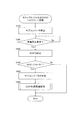
- FIG. 7 is a flowchart for explaining the flow of power generation permission determination according to the fifth embodiment.
- FIG. 1 is a diagram showing a configuration of a power supply system for a vehicle according to a first embodiment.
- FIG. 2 is a view showing a configuration of a power supply system for a vehicle according to a
- FIG. 8 is a view showing a configuration of a power supply system for a vehicle according to a sixth embodiment.
- FIG. 9 is a flowchart for explaining the flow of power generation permission determination according to the sixth embodiment.
- FIG. 10 is a flowchart for explaining the flow of SOFC stop related control according to the seventh embodiment.
- FIG. 11 is a diagram showing a configuration of a power supply system for a vehicle according to an eighth embodiment.
- FIG. 12 is a flow chart for explaining the flow of SOFC stop related control according to the eighth embodiment.
- FIG. 13 is a flowchart for explaining the flow of EAP process related control according to the eighth embodiment.
- FIG. 14 is a diagram showing a configuration of a power supply system for a vehicle according to a ninth embodiment.
- FIG. 15 is a flowchart for explaining the flow of control after termination of EAP according to the ninth embodiment.
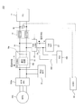
- FIG. 1 is a diagram for explaining a schematic configuration of a power supply system for a vehicle according to a first embodiment.
- the vehicle power supply system 100 includes a main battery 10 for supplying power to a traveling motor 200 of the vehicle and a SOFC (solid oxide fuel cell: solid oxide fuel cell for supplying power to the main battery 10).
- fuel cell 12 a main line 14 connecting the main battery 10 and the SOFC 12, an FC converter 16 as a first voltage converter disposed on the main line 14 to transform the output voltage of the SOFC 12, and an FC converter in the main line 14
- An FC connection relay 18 as a relay provided between the SOFC 12 and the SOFC 12, and a sub-battery 22 connected to an accessory power supply line 300 for supplying power to the vehicle or the accessory 400 of the SOFC 12.
- the traveling motor 200 is configured by a three-phase alternating current motor, receives power supply from the main battery 10 and the SOFC 12, and generates driving force of a vehicle on which the vehicle power supply system 100 is mounted.
- the traveling motor 200 functions as a generator according to the traveling state such as the operating state of a regenerative brake, for example, and supplies regenerative power to the main battery 10.
- the traveling motor 200 is provided with a motor inverter 200a that converts DC power supplied from the main battery 10 and the SOFC 12 into AC power while converting AC regenerative power generated by the traveling motor 200 into DC power. It is done.
- the main battery 10 is configured of, for example, a secondary battery such as a lithium ion battery.
- main battery 10 receives supply of electric power from an external charging device (not shown) and generated electric power of SOFC 12, and charges, while based on a request from electric motor 200, electric power being charged to the electric motor 200. Supply.
- the SOFC 12 is configured by stacking cells obtained by sandwiching an electrolyte layer formed of a solid oxide such as ceramic with an anode (fuel electrode) and a cathode (air electrode).
- the SOFC 12 receives the supply of fuel gas (hydrogen) to the fuel electrode and generates power by receiving the supply of oxidizing gas (oxygen) to the air electrode.
- the SOFC 12 in the present embodiment generates power when, for example, the charge power of the main battery 10 is insufficient for the traveling request, and the generated power is transmitted via the FC converter 16 through the main line 14 which is a power supply line. Supply to the main battery 10.
- the FC converter 16 is a DCDC converter that transforms (boosts) the power generated by the SOFC 12 and supplies it to the main battery 10 and the traveling motor 200.
- the FC converter 16 boosts the power supplied from the SOFC 12 to the main battery 10 in a state where the input-side capacitor 16a as a charging unit and the input-side capacitor 16a are charged on the side of the FC connection relay 18 (the SOFC 12 side).
- a transformer circuit 16 b constituted by circuit elements such as a coil or a transformer.
- the FC connection relay 18 is, for example, a normally open relay, and is controlled by the controller 90 in response to a request from the main battery 10 to the generated power of the SOFC 12 or the like.
- the sub battery 22 is a battery that supplies electric power to the electric component of the vehicle or the accessory 400 such as an air blower of the SOFC 12 through the accessory power supply line 300.
- the vehicle power supply system 100 of the present embodiment is configured to be able to supply the power stored in the sub-battery 22 to the input-side capacitor 16 a of the FC converter 16.
- the sub-battery 22 is connected in parallel between the FC connection relay 18 and the FC converter 16 (more specifically, the input-side capacitor 16a) in the main line 14 via the subline 24.
- a sub converter 26 as a second voltage converter is disposed in the sub line 24 to control the power supplied from the sub battery 22 to the input side capacitor 16 a.
- the sub-converter 26 is a DC-DC converter having a function of extracting power from the sub-battery 22 and charging the input-side capacitor 16 a based on a command from the controller 90.
- the power supply system 100 for vehicles is provided with the controller 90 which controls opening and closing of the FC connection relay 18.
- the controller 90 is constituted by a computer, particularly a microcomputer, provided with a central processing unit (CPU), a read only memory (ROM), a random access memory (RAM), and an input / output interface (I / O interface).
- the controller 90 is programmed to execute at least one process of the processes of the present embodiment and each of the embodiments described later.
- the controller 90 may be configured as one device, or may be divided into a plurality of devices, and each control of the present embodiment may be configured to be distributed and processed by the plurality of devices.
- the controller 90 acquires the FC output voltage detection value Vfc_d from the FC voltage sensor 30 as a fuel cell output voltage acquisition unit that detects the output voltage of the SOFC 12. Then, the controller 90 executes open / close control of the FC connection relay 18 and control of the sub converter 26 based on the FC output voltage detection value Vfc_d.
- the FC connection relay 18 is maintained in the open state.
- the FC connection relay 18 is closed and the generated power of the SOFC 12 is supplied to the main battery 10.
- the controller 90 controls the sub-converter 26 to charge the input-side capacitor 16a to a predetermined voltage, preferably with the FC connection relay 18 open.
- the voltage of the input-side capacitor 16 a will be simply referred to as “input-side capacitor voltage Vic”.
- the FC connection relay 18 can be closed, and the generation of inrush current can be suppressed.
- the sub-converter 26 is used to charge the input-side capacitor 16a. Therefore, the large FC converter 16 in which the power control to the high power system including the main battery 10 is assumed is performed while suppressing the power loss compared to the case where the difference between the output voltage of the SOFC 12 and the voltage of the main battery 10 is adjusted. The difference in voltage can be eliminated.
- the FC connection relay 18 is provided with a so-called precharge relay to close the precharge relay. It is conceivable to eliminate the potential difference between the SOFC 12 and the input side capacitor 16a. However, in this case, the SOFC 12 and the input-side capacitor 16a are energized via the precharge relay in a state where the preparation for power generation of the SOFC 12 is not completed and the output is not stable (the IV characteristic of the SOFC 12 is transient). It will be possible.
- charging of the input-side capacitor 16a by the sub-converter 26 is performed in a state where the FC connection relay 18 is opened and the conduction between the SOFC 12 and the input-side capacitor 16a is disconnected. Precharging is possible. Therefore, it is possible to cut off the conduction with the input-side capacitor 16a until the output of the SOFC 12 is stabilized, so that the input-side capacitor 16a is charged without performing the control for eliminating the potential difference fluctuation. be able to. That is, control relating to the charging can be simplified.
- the vehicle power supply system 100 connects the main battery 10 for supplying power to the traveling motor 200 of the vehicle, the SOFC 12 as a fuel cell for supplying power to at least the main battery 10, and the main battery 10 and the SOFC 12
- An FC converter 16 as a first voltage converter including a main line 14, an input-side capacitor 16 a as a charging unit disposed on the main line 14 and adjusting the output voltage of the SOFC 12, and a transformer circuit 16 b as a transformer unit
- An FC connection relay 18 as a relay provided between the FC converter 16 and the SOFC 12 in a line 14, and a sub-battery 22 connected to an accessory power supply line 300 for supplying power to the vehicle or the accessory 400 of the SOFC 12.
- the vehicle power supply system 100 is connected between the FC connection relay 18 and the input capacitor 16a in the main line 14 and serves as a second voltage converter for adjusting the power supplied from the sub battery 22 to the input capacitor 16a.
- a sub converter 26 is provided.
- the subconverter 26 is mainly used to charge the input-side capacitor 16a, the subconverter 26 is smaller in size than the large (large output) FC converter 16 in which the number of elements, wiring, and the like are complicated. it can. Therefore, compared with the case where the difference between the output voltage of SOFC 12 and the voltage of main battery 10 is adjusted using a large FC converter 16, the difference between the output voltage of SOFC 12 and the voltage of main battery 10 is eliminated while suppressing power loss. can do.
- the FC converter 16 is configured as a bidirectional converter. Has become more complicated and larger.
- the FC converter 16 can be configured as a one-way converter that boosts the voltage from the SOFC 12 toward the main battery 10, so the configuration of the FC converter 16 is also simplified. Be done. As a result, it is possible to realize the elimination of the difference between the output voltage of the SOFC 12 and the voltage of the main battery 10 while simplifying the configuration of the entire vehicle power supply system 100 more suitably.
- the vehicle power supply system 100 uses the FC voltage sensor 30 as a fuel cell output voltage acquisition unit that acquires the output voltage of the SOFC 12 and the FC output voltage detection value Vfc_d that is the acquired output voltage of the SOFC 12
- the controller 90 further includes a controller 90 that executes switching control of the FC connection relay 18 and control of the sub-converter 26.
- FC output voltage detection value Vfc_d it is possible to preferably block FC connection relay 18 at a timing at which rush current resulting from the difference between the open voltage of SOFC 12 and the voltage of main battery 10 can be suppressed. . Therefore, in a scene such as when the SOFC 12 starts up, the FC connection relay 18 can be closed at a timing when the difference between the FC output voltage detection value Vfc_d and the input-side capacitor voltage Vic becomes relatively small. It can be suitably suppressed.
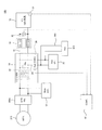
- FIG. 2 is a diagram showing a configuration of a vehicular power supply system 100 in the second embodiment.
- the transformer circuit 16 b of the FC converter 16 is omitted to simplify the drawing.
- the sub-converter 26 is integrated with the FC converter 16. More specifically, the sub-converter 26 is integrated with the FC converter 16 while being connected to the main line 14 between the sub-battery 22 and the input-side capacitor 16a as in the first embodiment. Thereby, it is possible to share circuit elements and wiring used for the control substrate, the power supply substrate, etc. included in the FC converter 16 and the sub-converter 26, and the system configuration can be further simplified.
- the sub-converter 26 mainly aims to supply power to the accessory 400 and charge the input-side capacitor 16a, assumed control power is smaller than that of the FC converter 16. . Therefore, the circuit configuration is simpler and the number of parts is smaller than that of the FC converter 16. Therefore, even if sub-converter 26 is incorporated into FC converter 16, charge control to input-side capacitor 16a described in the first embodiment can be realized without complicating the configuration of existing FC converter 16. .
- the sub converter 26 is integrally formed with the FC converter 16. Thereby, it is possible to share circuit elements and wiring used for the control substrate, the power supply substrate, etc. included in the FC converter 16 and the sub-converter 26, and the system configuration can be further simplified. As a result, it contributes to downsizing of the power supply system 100 for a vehicle.
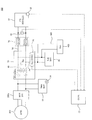
- FIG. 3 is a diagram showing the configuration of the vehicle power supply system 100 in the present embodiment.
- the FC converter 16 includes a transformer 40 as a transformer circuit 16 b between the SOFC 12 and the main battery 10. Therefore, the output voltage of the SOFC 12 is boosted by the transformer 40 and supplied to the main battery 10. More specifically, the transformer 40 is disposed on the secondary side (the main battery 10 side) of the input-side capacitor 16 a in the main line 14.
- the SOFC 12 of the present embodiment is configured such that the maximum output voltage is less than 60V. More specifically, for example, the number of stacked unit cells constituting the SOFC 12 is adjusted such that the maximum output voltage is less than 60V.
- the SOFC 12 when the maximum output voltage of the SOFC 12 is configured to be less than 60 V, the SOFC 12 can be removed from the target components of the high voltage safety request determined from the viewpoint of the safety of the vehicle.
- the voltage exceeds 60 V for safety reasons. It is required not to install voltage electrical components. However, since the maximum output voltage of the SOFC 12 of the present embodiment is less than 60 V, it does not fall under such a high voltage electrical component. Therefore, the SOFC 12 can be installed also in the front area and the rear area of the vehicle where the installation is not supposed.
- the transformer 40 of the FC converter 16 is interposed between the SOFC 12 not corresponding to the high voltage electrical component and the main battery 10 corresponding to the high voltage electrical component. Therefore, since the SOFC 12 and the main battery 10 are not directly wired, the SOFC 12 is substantially electrically isolated from the main battery 10 of the high voltage electrical component.
- the SOFC 12 can be more reliably made independent of the high voltage system including the main battery 10.
- the SOFC 12 can be installed in an arbitrary area of the vehicle including the collision area while satisfying the high voltage safety requirements, so that the freedom of the layout of the vehicle can be improved.
- the transformer (the transformer circuit 16 b) of the FC converter 16 is configured by the transformer 40.
- the SOFC 12 can be made independent of the high voltage system.
- SOFC12 is comprised so that the maximum output voltage may be less than 60V.
- the SOFC 12 can be removed from the target parts of the high voltage safety requirements defined from the viewpoint of the safety of the vehicle.
- the SOFC 12 can be made non-high voltage It is possible to cut off the direct electrical connection with the main battery 10 which is a high voltage electrical component while being a component. Therefore, the SOFC 12 can be installed in an arbitrary area of the vehicle including the collision area while satisfying the high voltage safety requirements, so that the freedom of the layout of the vehicle can be improved.
- the SOFC 12 having a high operating temperature can be separated from the other components as much as possible.
- the transformer 40 is provided to the FC converter 16 having a configuration in which the sub-converter 26 is integrated is described.
- the transformer 40 may be provided in the FC converter 16.
- the fourth embodiment will be described below.
- the same components as those in the first to third embodiments are denoted by the same reference numerals, and the detailed description thereof will be omitted.
- startup relay closing control the closing control of the FC connection relay 18 executed in the scene of activation of the SOFC 12 (hereinafter, “startup relay closing control”) Will also be described.
- FIG. 4 is a flowchart for explaining the flow of start-up relay closing control in the present embodiment.
- step S110 the controller 90 determines whether the SOFC 12 is activated. More specifically, the controller 90 determines that the SOFC 12 is activated when detecting a power generation request to the SOFC 12 when, for example, the remaining charge (SOC) of the main battery 10 falls below a predetermined value. Then, when it is determined that the SOFC 12 is activated, the controller 90 performs the process of step S120.
- SOC remaining charge
- step S120 the controller 90 charges the input-side capacitor 16a of the FC converter 16 with the FC connection relay 18 open. Specifically, the controller 90 controls the sub-converter 26 to charge the input capacitor 16a such that the input capacitor voltage Vic approaches the FC output voltage detection value Vfc_d. That is, the input side capacitor voltage Vic is brought close to the open circuit voltage of the SOFC 12 to suppress the voltage difference between the input side capacitor voltage Vic and the open circuit voltage of the SOFC 12.
- step S130 the controller 90 determines that the absolute value of the difference between the FC output voltage detection value Vfc_d and the input-side capacitor voltage Vic (hereinafter, "FC-also described as capacitor voltage difference absolute value
- is less than or equal to threshold voltage difference ⁇ Vth.
- step S140 the controller 90 closes the FC connection relay 18.
- step S120 to step S140 the FC connection relay 18 is closed in a state where the voltage difference between the input side capacitor voltage Vic and the open circuit voltage of the SOFC 12 is relatively small. Therefore, it is possible to suppress the occurrence of inrush current when the FC connection relay 18 is closed.
- the controller 90 determines whether the SOFC 12 is activated (step S110 in FIG. 4), and when it is determined that the SOFC 12 is activated, controls the subconverter 26 to To charge the input capacitor 16a (step S120 in FIG. 4). Then, the controller 90 closes the FC connection relay 18 after charging the input-side capacitor 16a (step S140 in FIG. 4).
- the input capacitor 16a when the SOFC 12 is started, the input capacitor 16a can be charged in a state where the FC connection relay 18 is open, and the input capacitor voltage Vic can be brought close to the open voltage of the SOFC 12. Therefore, the voltage difference between the input-side capacitor voltage Vic and the open circuit voltage of the SOFC 12 can be reduced, and the FC connection relay 18 can be closed in the state where the voltage difference is reduced. Generation of inrush current can be suppressed more reliably.
- the controller 90 sets the FC-capacitor voltage difference absolute value
- ⁇ Vfc_d as the difference between the input-side capacitor voltage Vic, which is the voltage of the input-side capacitor 16a, and the FC output voltage detection value Vfc_d. Is charged to the input-side capacitor 16a such that the threshold voltage difference .DELTA.Vth is equal to or smaller than -ic.vertline. (Steps S120 and S130 in FIG. 4).
- the controller 90 detects that there is a power generation request to the SOFC 12 when it determines that the SOFC 12 is activated, and charges the input-side capacitor 16a.
- the SOC of the main battery 10 is monitored to detect the prediction that the SOFC 12 needs to be started, and when the prediction is detected, before actually entering into the SOFC 12 start processing (detection of power generation request)
- the input capacitor 16a may be charged before the above.
- FIG. 5 is a flowchart for explaining the flow of start-up relay closing control in the present modification.
- the same step number is attached
- the controller 90 determines that the FC-capacitor voltage difference absolute value
- step S131 the controller 90 determines whether the FC-capacitor voltage difference ⁇ Vfc_d-ic obtained by subtracting the input-side capacitor voltage Vic from the FC output voltage detection value Vfc_d is 0 or more. That is, it is determined whether the FC output voltage detection value Vfc_d is equal to or higher than the input-side capacitor voltage Vic.
- the controller 90 determines that the FC output voltage detection value Vfc_d is equal to or higher than the input-side capacitor voltage Vic, the controller 90 closes the FC connection relay 18 in step S140.
- controller 90 determines in step S131 that FC output voltage detection value Vfc_d is less than input-side capacitor voltage Vic
- controller 90 discharges the power stored in input-side capacitor 16a in step S132.
- the controller 90 controls the sub-converter 26 to discharge the charging power from the input side capacitor 16 a to a discharge circuit built in the sub-converter 26 (not shown) or configured separately from the sub-converter 26.
- the FC connection relay 18 since the FC connection relay 18 is closed in a state where the output voltage of the SOFC 12 is higher than the input side capacitor voltage Vic, the current flowing at the time of the closing is directed from the SOFC 12 to the direction of the input side capacitor 16a. can do. Therefore, it is possible to suppress the flow of current from the input side capacitor 16a to the SOFC 12 when the FC connection relay 18 is closed.
- sub-converter 26 basically supplies power to input-side capacitor 16a under charge control in which FC-capacitor voltage difference absolute value
- the power is not supplied from the input side capacitor 16 a in the direction of the sub-converter 26). That is, basically, it is considered that the input-side capacitor voltage Vic is lower than the FC output voltage detection value Vfc_d during the charge control.
- start-up relay closing control is started in a state where the input side capacitor 16a has already been charged to some extent in a scene such as at the time of restarting after a short time stop of the SOFC 12.
- controller 90 controls sub-converter 26 to charge input-side capacitor 16a such that input-side capacitor voltage Vic is equal to or lower than FC output voltage detection value Vfc_d (see FIG. Steps S131 and S132 in FIG. 5).
- control for discharging the input capacitor 16a has been described as an example of the control for making the input capacitor voltage Vic equal to or lower than the output voltage of the SOFC 12.
- control to make the input-side capacitor voltage Vic other than this lower than the output voltage of the SOFC 12 may be adopted.
- the target value of the input-side capacitor voltage Vic is set lower by a predetermined margin with respect to the FC output voltage detection value Vfc_d within a range where FC-capacitor voltage difference absolute value
- the input-side capacitor voltage Vic may be maintained at or below the output voltage of the SOFC 12.
- the fifth embodiment will be described below.
- the same components as those in the first to fourth embodiments are denoted by the same reference numerals, and the detailed description thereof will be omitted.
- an aspect different from that of the fourth embodiment will be described with respect to the start-up relay closing control.
- the present embodiment will be described on the premise that it is based on the start-up relay closing control of the fourth embodiment shown in FIG. 4 from the viewpoint of simplifying the description, the fifth to ninth embodiments are implemented. In any of the embodiments, the start relay closing control according to the modification of the fourth embodiment shown in FIG. 5 may be based.
- FIG. 6 is a flowchart for explaining the flow of start-up relay closing control in the present embodiment.
- step S210 the controller 90 determines whether the SOFC 12 is activated as in the fourth embodiment.
- the controller 90 determines that the SOFC 12 is to be activated, the controller 90 performs the process of step S220.
- step S220 the controller 90 performs power generation permission determination to determine whether the power generation of the SOFC 12 is permitted. Specifically, in the start-up process of the SOFC 12, a warm-up process of heating the SOFC 12 with a start-up combustor or the like (not shown) is performed, and the temperature of the SOFC 12 gradually rises to a predetermined operating temperature (for example, 700.degree. Approaching 900 ° C). The SOFC 12 operates with the required power generation characteristics by reaching such an appropriate operating temperature.
- a predetermined operating temperature for example, 700.degree. Approaching 900 ° C.
- the warm-up process when the warm-up process is completed, it is determined that the power generation of the SOFC 12 is permitted. On the other hand, if the warm-up process of the SOFC 12 is not completed and the SOFC 12 does not reach the above-mentioned suitable operating temperature, there is a possibility that the SOFC 12 does not reach the required power generation characteristics. It is judged that the generation of electricity is not permitted.
- the power generation characteristic of the SOFC 12 is correlated with the magnitude of the open circuit voltage of the SOFC 12. That is, as the open circuit voltage of the SOFC 12 is larger, the power generation characteristic of the SOFC 12 is higher. Therefore, in the present embodiment, in the state where the FC connection relay 18 is open, the power generation permission of the SOFC 12 is determined based on the FC output voltage detection value Vfc_d as the open voltage of the SOFC 12.
- the content of specific power generation permission determination will be described.
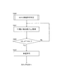
- FIG. 7 is a flowchart showing the process of determining whether the power generation of the SOFC 12 is permitted in the present embodiment.
- step S221 the controller 90 acquires an FC output voltage detection value Vfc_d from the FC voltage sensor 30.
- step S222 the controller 90 determines whether or not the FC output voltage detection value Vfc_d has reached the threshold voltage Vth1, that is, whether or not Vfc_d ⁇ Vth1.
- the threshold voltage Vth1 is suitably set as a reference for determining that the FC output voltage detection value Vfc_d can exhibit the normally required power generation characteristic of the SOFC 12 (determine that the warm-up process has ended).
- the controller 90 determines that the FC output voltage detection value Vfc_d is equal to or higher than the threshold voltage Vth1, the controller 90 determines that the power generation of the SOFC 12 is permitted, and proceeds to step S230.
- controller 90 passes through the processing of step S230, step S240 and step S250 similarly to the processing of step S120, step S130 and step S140 of FIG. 5 according to the fourth embodiment. Block the
- the FC connection relay 18 can be closed in a state where the power generation of the SOFC 12 is permitted and the power generation characteristics are stable. That is, the FC connection relay 18 can be closed in a region where the change in output voltage is relatively small with respect to the current drawn from the SOFC 12.
- the FC connection relay 18 when the FC connection relay 18 is closed in a state where the output voltage of the SOFC 12 is equal to or higher than the input-side capacitor voltage Vic, the current flows from the SOFC 12 to the input-side capacitor 16a, whereby the output voltage of the SOFC 12 is large.
- the controller 90 determines whether the power generation of the SOFC 12 is permitted when the SOFC 12 is activated (step S220 in FIG. 6), and determines that the power generation of the SOFC 12 is permitted. Then, the sub converter 26 is controlled to charge the input-side capacitor 16a (step S230 in FIG. 6), and the FC connection relay 18 is closed after the input-side capacitor 16a is charged (step S250 in FIG. 6). In particular, the controller 90 determines whether the power generation of the SOFC 12 is permitted based on whether the FC output voltage detection value Vfc_d is equal to or higher than the threshold voltage Vth1 (step S222 in FIG. 7). When the detected value Vfc_d is equal to or higher than the threshold voltage Vth1, it is determined that the power generation of the SOFC 12 is permitted (step S223 in FIG. 7).
- the power generation of the SOFC 12 is permitted, and a state in which the power generation characteristics are stable can be detected more reliably, and the FC connection relay 18 can be closed at the stable timing. That is, the FC connection relay 18 can be closed in a region where the change in output voltage is relatively small with respect to the current drawn from the SOFC 12. Thereby, when the current is extracted from the SOFC 12 for supply to the main battery 10 or the like after the closing of the FC connection relay 18, hunting of the voltage caused by the fluctuation of the output voltage of the SOFC 12 can be suppressed.
- the FC connection relay 18 will not be blocked. Therefore, it is possible to more reliably detect the case where the above-mentioned voltage hunting is concerned because the power generation of the SOFC 12 is not stabilized due to these other factors, and the FC connection relay 18 is not blocked. As a result, generation of inrush current when the FC connection relay 18 is blocked can be suppressed more reliably.
- the controller 90 determines whether the power generation of the SOFC 12 is permitted based on the FC output voltage detection value Vfc_d.
- the controller 90 applies a relatively small predetermined load to the SOFC 12, and changes the output current of the SOFC 12 by the load, and the power generation characteristic of the SOFC 12 based on the change of the FC output voltage detection value Vfc_d before and after applying the load. If the estimated power generation characteristic reaches a predetermined power generation characteristic threshold, it may be determined that power generation is permitted.
- the sixth embodiment will be described below.
- the same components as those in the first to fifth embodiments are denoted by the same reference numerals, and the detailed description thereof will be omitted.
- the power generation permission determination of the SOFC 12 in the block control of the FC connection relay 18 is performed based on the temperature (stack temperature Ts) of the SOFC 12 instead of the FC output voltage detection value Vfc_d of the fifth embodiment.
- FIG. 8 is a diagram showing a configuration of a vehicle power supply system 100 in the present embodiment.
- the power supply system 100 for a vehicle is provided with a stack temperature sensor 32 for detecting the temperature of the SOFC 12 based on the system configuration (see FIG. 3) described in the third embodiment. There is. Then, the stack temperature detection value Ts_d detected by the stack temperature sensor 32 is appropriately transmitted to the controller 90.
- the flow of the start-up relay closing control in this embodiment is the same as the flow shown in FIG. 6 according to the fifth embodiment, so only the part of the power generation permission determination that differs from the fifth embodiment will be described.
- FIG. 9 is a flowchart showing the process of determining whether the power generation of the SOFC 12 is permitted in the present embodiment.
- step S221 ′ the controller 90 acquires the stack temperature detection value Ts_d from the stack temperature sensor 32.
- step S222 ' the controller 90 determines whether or not the stack temperature detection value Ts_d has reached the first threshold temperature Tth1, that is, whether or not Ts_d ⁇ Tth1.
- the first threshold temperature Tth1 is determined from the viewpoint of whether the stack temperature detection value Ts_d is a temperature at which the power generation characteristic of the SOFC 12 normally required is obtained.
- the controller 90 determines that the power generation of the SOFC 12 is permitted in step S223 ′, and the step of FIG. 6 according to the fifth embodiment. After the processing of S230, step S240, and step S250, the FC connection relay 18 is closed.
- the present embodiment it is possible to more reliably detect that the stack temperature Ts has reached the predetermined operating temperature, and to close the FC connection relay 18.
- the increase in the stack temperature Ts accompanying the progress of the warm-up process correlates with the improvement of the power generation characteristic of the SOFC 12. Therefore, by determining whether the power generation of the SOFC 12 is permitted based on the stack temperature detection value Ts_d, the time when the power generation characteristic of the SOFC 12 becomes the required characteristic is suitably detected, and the FC connection relay 18 is Can be closed.
- the vehicle power supply system 100 further includes a stack temperature sensor 32 that is a fuel cell temperature acquisition unit that acquires a stack temperature detection value Ts_d as the temperature of the SOFC 12. Then, the controller 90 determines whether the power generation of the SOFC 12 is permitted based on whether the stack temperature detection value Ts_d is equal to or higher than the first threshold temperature Tth1 (step S222 ′ in FIG. 9). When the temperature is equal to or higher than the first threshold temperature Tth1, it is determined that the power generation of the SOFC 12 is permitted (step S223 ′ in FIG. 9).
- the FC connection relay 18 can be more reliably closed at a timing when the change in output voltage is relatively small with respect to the current drawn from the SOFC 12.
- the above-described hunting of the voltage caused by the fluctuation of the output voltage of the SOFC 12 is suppressed more preferably. be able to.
- the stack temperature Ts can be regarded as a parameter representing the power generation characteristic of the SOFC 12 in fact.
- the power generation characteristics of the SOFC 12 can be grasped with high accuracy, and the FC connection relay 18 can be closed at an appropriate timing. As a result, generation of inrush current when the FC connection relay 18 is blocked can be suppressed more reliably.
- the stack temperature sensor 32 for detecting the temperature is provided in the SOFC 12 based on the system configuration (see FIG. 3) described in the third embodiment, and the block control of the FC connection relay 18 and the related control
- the example of performing the power generation permission determination in the block control has been described.
- the present invention is not limited to this, and based on the system configuration (see FIG. 1) described in the first embodiment (see FIG. 1) and the system configuration described in the second embodiment (see FIG. 2)
- a sensor 32 may be provided to perform the block control of the FC connection relay 18 and the power generation permission determination in the block control.
- the power generation permission determination may be performed using the output voltage of the SOFC 12 (the FC output voltage detection value Vfc_d). For example, when both the stack temperature detection value Ts_d and the FC output voltage detection value Vfc_d become equal to or higher than the first threshold temperature Tth1 and the threshold voltage Vth1, respectively, it is determined that the power generation of the SOFC 12 is permitted. Also good.
- the stack temperature Ts can usually be a parameter representing the power generation characteristic of the SOFC 12.
- the stack temperature detection value Ts_d is equal to or higher than the first threshold temperature Tth1 because the warm-up processing itself is normally performed or the stoichiometric ratio of the fuel and air supplied to the SOFC 12 is not appropriate.
- the desired power generation characteristics can not be obtained. In this case, since the power generation characteristic is actually low and the preparation of the SOFC 12 is not sufficient, it is preferable that it is judged that the power generation is not permitted.
- the stack temperature detection value Ts_d is equal to or higher than the first threshold temperature Tth1 by performing the power generation permission determination of the SOFC 12 based on both the stack temperature detection value Ts_d and the FC output voltage detection value Vfc_d as described above. Even if there is, since the FC output voltage detection value Vfc_d does not become equal to or higher than the threshold voltage Vth1, it is possible to more reliably detect a state where the above-described desired power generation characteristic is not obtained and to judge that power generation is not permitted. .
- the open circuit voltage of the SOFC 12 becomes higher than expected due to factors such as individual differences of unit cells constituting the SOFC 12, and the FC output voltage detection value Vfc_d is not obtained even though the SOFC 12 has not reached desired power generation characteristics. Is assumed to be equal to or higher than the threshold voltage Vth1. In this case, since the warm-up process is not actually completed, it can be determined that the stack temperature detection value Ts_d does not become equal to or higher than the first threshold temperature Tth1 and that power generation is not permitted.
- blockade of the FC connection relay 18 can be performed more reliably by suppressing the generation of the inrush current by determining whether the SOFC 12 is allowed to generate power based on both the stack temperature detection value Ts_d and the FC output voltage detection value Vfc_d. can do.
- the seventh embodiment will be described below.
- the same components as those in the first to sixth embodiments are denoted by the same reference numerals, and the detailed description thereof will be omitted.
- the FC connection relay 18 is blocked by the start-up relay blocking control (see FIGS. 4 to 6) described in the fourth to sixth embodiments.
- the start-up relay blocking control see FIGS. 4 to 6 described in the fourth to sixth embodiments.
- FIG. 10 is a flowchart showing the flow of SOFC stop related control in the present embodiment.
- step S140 when the FC connection relay 18 is closed in step S140 (see FIG. 4) or step S250 (see FIG. 6), the controller 90 executes SOFC stop related control after step S310.
- step S310 the controller 90 stops the subconverter 26.
- the controller 90 deactivates the sub-converter 26 substantially simultaneously with (in response to the occlusion) the occlusion of the FC connection relay 18.
- the sub-converter 26 is used to control charging of the input-side capacitor 16a when the SOFC 12 is started, and basically, the need to operate the SOFC 12 during operation is low. Therefore, as in the present embodiment, by stopping the sub-converter 26 promptly in conjunction with the closing of the FC connection relay 18, it is possible to suppress the power consumption due to continuing the useless operation of the sub-converter 26.
- step S320 the controller 90 determines whether or not there is a power generation stop request of the SOFC 12 after stopping the sub-converter 26 as described above. Specifically, the controller 90 determines that there is a power generation stop request by detecting an operation of a predetermined SOFC stop operation switch (not shown), for example.
- step S330 the controller 90 stops the SOFC 12. Specifically, the controller 90 issues, for example, a command to stop the SOFC system provided with a fuel system or an air system actuator for generating the SOFC 12. According to this command, the fuel supply to the SOFC 12 is stopped, and a stop sequence including the cooling process of the SOFC 12 is executed.
- controller 90 reactivates sub-converter 26. This is for controlling the applied voltage of the EAP process by the sub-converter 26 in relation to the later-described EAP (Electric Anode Protection) process performed to suppress the oxidation deterioration of the anode catalyst at the time of stopping the SOFC 12.
- EAP Electro Anode Protection
- step S350 the controller 90 executes EAP processing as fuel cell protection processing.
- the EAP treatment is a protective voltage of a desired magnitude that is a voltage opposite to a voltage obtained by power generation of the SOFC 12
- This is a process of supplying a current of a predetermined magnitude (hereinafter also referred to as “EAP current”) to the SOFC 12 so as to be applied to the SOFC 12.
- the sub battery 22 is used as a power supply for EAP processing, and the EAP current is adjusted by the sub converter 26. That is, in the present embodiment, the controller 90 controls the sub-converter 26 to adjust the power extracted from the sub-battery 22 to control the EAP current to a desired magnitude.
- the FC connection relay 18 when the EAP processing is performed, the FC connection relay 18 is in a closed state, so that it is possible to supply the EAP current from the sub-battery 22 to the SOFC 12.
- the sub-converter 26 of this embodiment is smaller than the FC converter 16 because it is used to execute the above-described EAP processing in addition to the charging of the input-side capacitor 16a at the time of startup of the SOFC 12 described in the fourth embodiment. It is desirable that the output be slightly larger than in the case where only the charge control to the input side capacitor 16a is performed while the output is made.
- step S360 the controller 90 determines whether the stack temperature detection value Ts_d obtained by the stack temperature sensor 32 is less than or equal to a predetermined second threshold temperature Tth2.
- the reaction in which the catalyst in the anode electrode is oxidized does not occur below the oxidative degradation point (for example, a temperature between 400 ° C. and 500 ° C.) It has been known. That is, the oxidative degradation point is the lower limit of the temperature at which oxidative degradation of the anode occurs. Therefore, when the temperature of the SOFC 12 decreases due to the cooling process included in the SOFC 12 stop sequence, the EAP process can be stopped if the temperature is lower. Therefore, in the present embodiment, it is determined whether the stack temperature detection value Ts_d is equal to or lower than the second threshold temperature Tth2 as the determination as to whether or not the EAP processing is to be stopped.
- the stack temperature detection value Ts_d is equal to or lower than the second threshold temperature Tth2 as the determination as to whether or not the EAP processing is to be stopped.
- the second threshold temperature Tth2 it is preferable to set the second threshold temperature Tth2 to a temperature at or near the oxidation deterioration point.
- the controller 90 determines that the stack temperature detection value Ts_d is equal to or lower than the second threshold temperature Tth2, the controller 90 ends the EAP processing in step S370. Specifically, the controller 90 controls the sub-converter 26 to set the EAP current to zero.
- the controller 90 appropriately opens the FC connection relay 18 and stops the sub-converter 26 again.
- the controller 90 stops the sub-converter 26 (step S310 in FIG. 10).
- the sub-converter 26 can be promptly stopped in conjunction with the closing of the FC connection relay 18, and power consumption due to continuing the useless operation of the sub-converter 26 can be suppressed.
- the controller 90 determines whether there is a power generation stop request for the SOFC 12 (step S320 in FIG. 10). If so, the power generation of the SOFC 12 is stopped (step S330 in FIG. 10), and the subconverter 26 is reactivated while the FC connection relay 18 is closed (step S340 in FIG. 10). 26 is controlled to execute EAP processing as fuel cell protection processing for applying a predetermined voltage from the sub-battery 22 to the SOFC 12 (step S350 in FIG. 10).
- the FC connection relay 18 is in a closed state, so that it is possible to supply the EAP current from the sub-battery 22 to the SOFC 12. And, by supplying the EAP current from the sub-battery 22 to the SOFC 12 using the sub-converter 26, the EAP processing can be executed without providing another converter or battery for performing the EAP processing. .
- the existing system configuration can be simplified, and the relay at startup can be performed. Both blocking control and EAP processing at the time of stopping can be realized.
- the system configuration can be further simplified as compared with the existing system in which the FC converter 16 is bidirectionalized to execute EAP processing.
- the vehicle power supply system 100 includes a stack temperature sensor 32 (see FIG. 8) as a temperature acquisition unit of a fuel cell that acquires a stack temperature detection value Ts_d that is the temperature of the SOFC 12.
- a stack temperature sensor 32 see FIG. 8 as a temperature acquisition unit of a fuel cell that acquires a stack temperature detection value Ts_d that is the temperature of the SOFC 12.
- the EAP processing can be ended promptly. Therefore, the power consumption of the EAP processing can be suppressed.
- the second threshold temperature Tth2 is set to an oxidation deterioration point as a temperature at which oxidation deterioration in the anode electrode of the SOFC 12 occurs.
- the EAP processing can be terminated at a timing when the stack temperature Ts falls below an oxidation deterioration point at which the catalyst oxidation in the anode electrode theoretically does not occur. That is, since the EAP processing can be terminated at a more appropriate timing, the power consumption of the EAP processing can be suppressed, and the effect of suppressing the oxidation deterioration due to the EAP processing can be more reliably exhibited.
- the sub-converter 26 is stopped during the operation of the SOFC 12 (see step S310 in FIG. 10).
- the subconverter 26 may be kept operating while the SOFC 12 is operating.
- SOFC stop related control in that case is the process of step S310 (stop of the subconverter 26) and the process of step S340 (reconversion of the subconverter 26) to the SOFC stop related control of FIG. 10 described in this embodiment. It is similar except that the operation is removed.
- FIG. 11 is a diagram showing a configuration of a vehicular power supply system 100 in the present embodiment.
- this vehicle power supply system 100 is an SOC sensor for detecting the charge amount (SOC) of the main battery 10 based on the system configuration (see FIG. 3) described in the third embodiment. 34 are provided.
- the SOC sensor 34 detects, for example, the voltage and charge / discharge current of the main battery 10, and calculates the charge amount of the main battery 10 from the integrated value of the voltage and current. Then, the charge amount detection value (hereinafter, referred to as “charge amount detection value SOC_d”) detected by the SOC sensor 34 is appropriately transmitted to the controller 90.
- charge amount detection value SOC_d the charge amount detection value detected by the SOC sensor 34 is appropriately transmitted to the controller 90.
- FIG. 12 is a flowchart showing the flow of SOFC stop related control in the present embodiment.
- step S410 the controller 90 executes the process of step S410 and subsequent steps. Note that each process from step S410 to step S430 shown in the figure is the same as each process from step S310 to step S330 of the seventh embodiment, and thus detailed description will be omitted.
- step S430 the controller 90 determines in step S440 whether or not the charge amount detection value SOC_d obtained by the SOC sensor 34 exceeds a predetermined first charge amount threshold ⁇ th1. .
- the main battery 10 sufficiently charged to such an extent that the power required for the traveling of the vehicle is not short for a predetermined period of time even if the SOFC 12 is stopped? It is a threshold defined from the viewpoint of whether or not. That is, if it is assumed that the main battery 10 is charged with sufficient power to drive for the predetermined time, it is considered that the time until the power generation request for the SOFC 12 is issued again becomes longer. Is expected to last long. On the other hand, when the power of the main battery 10 is insufficient for the power required for traveling of the vehicle for a predetermined time, it is considered that the time until the second power generation request to the SOFC 12 is issued becomes short.
- the power of the main battery 10 is sufficient for the power required to drive the vehicle for a predetermined period of time, it is predicted that the power generation stop state of the SOFC 12 will continue for a long time.
- the supply stop time will also be longer.
- the reduction of the fuel gas partial pressure in the anode proceeds and the inside of the anode is more likely to become an oxidizing atmosphere. Therefore, in this case, since it is highly necessary to execute the EAP process to suppress the oxidation degradation of the anode catalyst, the EAP process is performed (after “Yes” in step S440).
- the controller 90 determines that the charge amount detection value SOC_d is equal to or less than the first charge amount threshold ⁇ th1, the controller 90 ends the present SOFC stop related control. On the other hand, when the controller 90 determines that the detected charge amount SOC_d exceeds the first charge amount threshold ⁇ th1, the controller 90 executes the process of step S450.
- step S450 controller 90 reactivates subconverter 26. Then, the controller 90 executes EAP process related control in the subsequent step S460.
- FIG. 13 is a flowchart showing the details of EAP process related control.
- step S461 the controller 90 starts EAP processing.
- step S462 the controller 90 determines whether the stack temperature detection value Ts_d is equal to or lower than a second threshold temperature Tth2.
- the controller 90 ends the EAP process as in the seventh embodiment (step S465).
- step S463 when the controller 90 determines that the stack temperature detection value Ts_d exceeds the second threshold temperature Tth2, the controller 90 executes the determination process of step S463.
- step S463 the controller 90 determines whether there is another power generation request for the SOFC 12. Then, if it is determined that the power generation request for the SOFC 12 is made again, the controller 90 executes the determination processing of step S464.
- step S464 the controller 90 determines whether fuel supply to the SOFC 12 has been started. That is, the controller 90 determines whether fuel supply to the SOFC 12 is started at the stage where the start-up process of the SOFC 12 is being performed based on the second power generation request.
- step S465 ends the EAP processing. That is, when the fuel supply to the SOFC 12 is started, the oxidizing atmosphere in the anode electrode is eliminated by the fuel supply, and the oxidation deterioration of the anode electrode catalyst does not substantially occur, so the EAP processing is ended.
- step S463 On the premise that the stack temperature detection value Ts_d is not less than or equal to the second threshold temperature Tth2 (“No” in step S462), the process in step S463 is repeated. In the determination of whether or not there is a power generation request, and in the determination of whether or not the fuel supply to the SOFC 12 is started in step S464, if at least one of them is negative, the EAP processing is continued. It becomes.
- EAP is started when fuel supply is started based on the second SOFC 12 start request. Since the process is stopped, it is possible to suppress the power consumption by continuing the EAP process unnecessarily.
- the vehicle power supply system 100 further includes an SOC sensor 34 (FIG. 11) as a charge amount acquisition unit that acquires the charge amount of the main battery 10. Then, after stopping the sub-converter 26 (step S410 in FIG. 12), the controller 90 determines whether there is a power generation stop request for the SOFC 12 (step S420 in FIG. 12). If so, the power generation of the SOFC 12 is stopped (step S430 in FIG.
- step S460 applying a predetermined voltage from the sub battery 22 to the SOFC 12 by controlling the reactivated sub converter 26 It performs EAP process that (step S460 in FIG. 12).
- the FC connection relay 18 is in a closed state, so that it is possible to supply the EAP current from the sub-battery 22 to the SOFC 12. And, by supplying the EAP current from the sub-battery 22 to the SOFC 12 using the sub-converter 26, the EAP processing can be executed without providing another converter or battery for performing the EAP processing. .
- the sub-converter 26 when the detected charge amount SOC_d of the main battery 10 exceeds the first charge amount threshold ⁇ th1, the sub-converter 26 is reactivated to execute the EAP process. That is, when the power of the main battery 10 is sufficient for the power required for traveling the vehicle for the predetermined time, the EAP processing is performed.
- the stop time of the SOFC 12 is short, and the anode electrode is short enough to cause oxidation deterioration of the anode catalyst.
- the decrease in fuel gas partial pressure will not progress. Therefore, in the present embodiment, it is possible to appropriately determine this situation and not to execute the EAP process. Therefore, power consumption can be reduced by not executing EAP processing as much as possible.
- the travel time of the vehicle is set or predicted, and the vehicle requests while the SOFC 12 is stopped based on the set or predicted travel time of the vehicle. It is also possible to calculate the predicted value of the power consumption to be performed, and to determine the first charge amount threshold ⁇ th1, which is a criterion for determining whether or not to perform the EAP process, based on the predicted value of the power consumption.
- step S464 in FIG. 13 the EAP processing is ended (step S465 in FIG. 13).
- the ninth embodiment will be described below.
- the same components as those in the first to eighth embodiments are denoted by the same reference numerals, and the detailed description thereof will be omitted.
- control after EAP termination after termination of the EAP processing described in step S370 of FIG. 10 or step S490 of FIG. 12 will be described.
- FIG. 14 is a diagram showing a configuration of a vehicle power supply system 100 in the present embodiment.
- the power supply system 100 for a vehicle is provided with the stack temperature sensor 32 and the SOC sensor 34 in the system configuration (see FIG. 2) described in the second embodiment, and the output of the SOFC 12 is 60 V or more
- the discharge circuit 26 a is incorporated in the sub converter 26.
- the discharge circuit 26 a discharges the charging power of the input side capacitor 16 a in response to a command from the controller 90.
- FIG. 15 is a flow chart showing the flow of control after the end of EAP in the present embodiment.
- step S370 when the FC connection relay 18 is closed in step S370 (see FIG. 10) or step S490 (see FIG. 12), the controller 90 executes control after the end of EAP in step S510 and thereafter.
- step S510 the controller 90 controls the sub-converter 26 to discharge the charging power of the input-side capacitor 16a by the discharging circuit 26a. Thereby, the input side voltage of the FC converter 16 can be reduced more reliably.
- the output of the SOFC 12 is 60 V or more, it is desirable to quickly reduce the input side voltage of the FC converter 16 when the vehicle or the SOFC 12 is stopped. Therefore, in the present embodiment, by discharging the charging power of the input-side capacitor 16a by the discharging circuit 26a, the above-described safety requirement can be more preferably satisfied.
- the controller 90 opens the FC connection relay 18 in step S520.
- step S530 controller 90 stops sub-converter 26 again.
- the sub-converter 26 includes a discharge circuit 26a (see FIG. 14). Then, when the EAP processing is completed, the controller 90 causes the discharging circuit 26 a of the sub-converter 26 to discharge the power charged in the input-side capacitor 16 a of the FC converter 16 while closing the FC connection relay 18 (FIG. Step S510) When the power of the input side capacitor 16a is discharged, the FC connection relay 18 is opened (Step S520 in FIG. 15), and the sub-converter 26 is stopped (Step S530 in FIG. 15).
- the discharge circuit 26 a that discharges the input-side capacitor 16 a is provided in the sub-converter 26 that can be configured smaller than the FC converter 16. Therefore, for example, as compared with the case where the large-sized FC converter 16 is a bidirectional converter and the input-side capacitor 16a is discharged by the FC converter 16, power consumption by the operation of the converter can be reduced and the circuit configuration is simplified. can do.
- the discharge circuit 26a is incorporated in the sub-converter 26 based on the configuration of the vehicle power supply system 100 shown in FIG.
- the present invention is not limited to this, and the discharge circuit 26a may be incorporated in the sub-converter 26 based on the configuration of the vehicle power supply system 100 shown in FIG. 1, FIG. 3, FIG.
- each above-mentioned embodiment showed only a part of application example of the present invention, and limited the technical scope of the present invention to the concrete composition of each above-mentioned embodiment. It is not the purpose to do.
- the configuration of vehicle power supply system 100 shown in FIGS. 1 to 3, 8, 11, and 14 is merely an example of a specific embodiment that can realize the present invention, and is not necessarily limited to these configurations. It is not a thing. That is, the configuration of the vehicular power supply system 100 can be appropriately modified within the scope of the subject matter of the present invention.
- the charging portion of the sub-converter 26 is configured by the input-side capacitor 16a.
- the charging unit may be configured by any other circuit element or circuit configuration that can be conceived by those skilled in the art other than the capacitor, as long as it can adjust the input side voltage of sub converter 26 according to the output voltage of SOFC 12. It is good.
- the present invention can be appropriately applied to a vehicle power supply system provided with a fuel cell of a solid polymer type other than SOFC 12, a fuel cell stack, or a laminated fuel cell in which the fuel cells are stacked.
- the above embodiments can be combined as appropriate.
- the system configuration of the vehicle power supply system 100 described in the first to third embodiments, the startup relay closing control described in the fourth to sixth embodiments, the SOFC described in the seventh and eighth embodiments can be combined with each other as appropriate.
- ⁇ Vfc_d-ic An example of closing the FC connection relay 18 when the difference ⁇ Vth or less is described.
- the block determination of the FC connection relay 18 may be applied based on whether or not it is not.
Abstract
La présente invention concerne un système de source d'alimentation pour un véhicule qui comprend : une batterie principale qui fournit de l'électricité à un moteur de traction du véhicule ; une pile à combustible qui fournit de l'électricité à au moins la batterie principale ; une ligne principale qui relie la batterie principale et la pile à combustible ; un premier transformateur de tension qui est agencé sur la ligne principale et qui comprend une unité de charge et une unité de transformateur pour ajuster la tension de sortie de la pile à combustible ; un relais qui est disposé sur la ligne principale entre l'unité de charge et la pile à combustible ; et une sous-batterie qui est connectée à une ligne d'alimentation électrique de dispositif auxiliaire pour fournir de l'électricité au véhicule ou à un dispositif auxiliaire de la pile à combustible. Le système de source d'alimentation de véhicule est pourvu d'un deuxième transformateur de tension qui est connecté sur la ligne principale entre le relais et l'unité de charge et qui ajuste l'électricité fournie par la sous-batterie à l'unité de charge.
Priority Applications (5)
| Application Number | Priority Date | Filing Date | Title |
|---|---|---|---|
| EP17921702.1A EP3670241B1 (fr) | 2017-08-14 | 2017-08-14 | Système de source d'alimentation pour véhicule |
| JP2019536373A JP6888681B2 (ja) | 2017-08-14 | 2017-08-14 | 車両用電源システム |
| PCT/JP2017/029319 WO2019035172A1 (fr) | 2017-08-14 | 2017-08-14 | Système de source d'alimentation pour véhicule |
| US16/630,973 US10862148B2 (en) | 2017-08-14 | 2017-08-14 | Vehicle power source system |
| CN201780093707.3A CN110997395B (zh) | 2017-08-14 | 2017-08-14 | 车辆用电源系统 |
Applications Claiming Priority (1)
| Application Number | Priority Date | Filing Date | Title |
|---|---|---|---|
| PCT/JP2017/029319 WO2019035172A1 (fr) | 2017-08-14 | 2017-08-14 | Système de source d'alimentation pour véhicule |
Publications (1)
| Publication Number | Publication Date |
|---|---|
| WO2019035172A1 true WO2019035172A1 (fr) | 2019-02-21 |
Family
ID=65361917
Family Applications (1)
| Application Number | Title | Priority Date | Filing Date |
|---|---|---|---|
| PCT/JP2017/029319 WO2019035172A1 (fr) | 2017-08-14 | 2017-08-14 | Système de source d'alimentation pour véhicule |
Country Status (5)
| Country | Link |
|---|---|
| US (1) | US10862148B2 (fr) |
| EP (1) | EP3670241B1 (fr) |
| JP (1) | JP6888681B2 (fr) |
| CN (1) | CN110997395B (fr) |
| WO (1) | WO2019035172A1 (fr) |
Cited By (6)
| Publication number | Priority date | Publication date | Assignee | Title |
|---|---|---|---|---|
| JP2021118064A (ja) * | 2020-01-23 | 2021-08-10 | 株式会社豊田自動織機 | 燃料電池システム |
| WO2021244899A1 (fr) * | 2020-06-04 | 2021-12-09 | Robert Bosch Gmbh | Procédé et dispositif de charge d'un condensateur de circuit intermédiaire dans un réseau haute tension |
| CN114179615A (zh) * | 2020-09-15 | 2022-03-15 | 郑州宇通客车股份有限公司 | 一种燃料电池车辆的碰撞处理控制方法及系统 |
| CN115071456A (zh) * | 2022-06-13 | 2022-09-20 | 一汽解放汽车有限公司 | Sofc增程系统的控制方法、sofc增程系统及车辆 |
| JP7352995B2 (ja) | 2019-12-31 | 2023-09-29 | 永安行科技股▲フン▼有限公司 | 水素燃料電池スタックの給電方法及びシステム、水素燃料駆動原付車両とその伝動方法及びシステム |
| CN115071456B (zh) * | 2022-06-13 | 2024-05-14 | 一汽解放汽车有限公司 | Sofc增程系统的控制方法、sofc增程系统及车辆 |
Families Citing this family (5)
| Publication number | Priority date | Publication date | Assignee | Title |
|---|---|---|---|---|
| JP7066529B2 (ja) * | 2018-05-31 | 2022-05-13 | 矢崎総業株式会社 | Dc/dc変換ユニット |
| JP7094780B2 (ja) * | 2018-05-31 | 2022-07-04 | 矢崎総業株式会社 | Dc/dc変換ユニット |
| JP7226299B2 (ja) * | 2019-12-23 | 2023-02-21 | トヨタ自動車株式会社 | 燃料電池車両 |
| US11628740B2 (en) * | 2020-10-29 | 2023-04-18 | Argo AI, LLC | Devices, systems, and methods for mitigating vehicle power loss in battery mode |
| JP7396262B2 (ja) * | 2020-12-21 | 2023-12-12 | トヨタ自動車株式会社 | 燃料電池システムおよび燃料電池システムの制御方法 |
Citations (5)
| Publication number | Priority date | Publication date | Assignee | Title |
|---|---|---|---|---|
| JP2004234907A (ja) * | 2003-01-28 | 2004-08-19 | Nissan Motor Co Ltd | 燃料電池車両用電源システム |
| JP2007305372A (ja) * | 2006-05-10 | 2007-11-22 | Honda Motor Co Ltd | 燃料電池システムにおけるコンタクタ故障検知装置 |
| JP2008017576A (ja) * | 2006-07-04 | 2008-01-24 | Suzuki Motor Corp | 車両用制御装置 |
| JP2008084628A (ja) | 2006-09-27 | 2008-04-10 | Toyota Motor Corp | 燃料電池システム及び燃料電池の始動方法 |
| JP2011010508A (ja) * | 2009-06-29 | 2011-01-13 | Toyota Motor Corp | 電源システム |
Family Cites Families (14)
| Publication number | Priority date | Publication date | Assignee | Title |
|---|---|---|---|---|
| JP3625789B2 (ja) * | 2001-08-10 | 2005-03-02 | 本田技研工業株式会社 | 車両の電源装置 |
| JP4874874B2 (ja) * | 2007-06-06 | 2012-02-15 | トヨタ自動車株式会社 | 車両の電源装置 |
| CN102510815A (zh) * | 2009-07-03 | 2012-06-20 | Inkar-M科研生产企业股份有限公司 | 电动车辆 |
| JP5308268B2 (ja) * | 2009-08-05 | 2013-10-09 | 本田技研工業株式会社 | 電力供給システム |
| WO2011099157A1 (fr) * | 2010-02-15 | 2011-08-18 | トヨタ自動車株式会社 | Système d'alimentation électrique et véhicule équipé de ce système |
| WO2012063331A1 (fr) | 2010-11-10 | 2012-05-18 | トヨタ自動車株式会社 | Système d'alimentation pour véhicule électrique, son procédé de commande et véhicule électrique |
| US9172252B2 (en) * | 2011-04-21 | 2015-10-27 | Toyota Jidosha Kabushiki Kaisha | Power supply apparatus for electrically powered vehicle and method for controlling the same |
| KR101284331B1 (ko) * | 2011-12-09 | 2013-07-08 | 성균관대학교산학협력단 | 친환경 차량의 충전장치 및 방법 |
| CN105594044B (zh) * | 2013-10-09 | 2018-04-27 | 日产自动车株式会社 | 燃料电池系统 |
| JP5880582B2 (ja) * | 2014-01-10 | 2016-03-09 | トヨタ自動車株式会社 | 車両 |
| US9819192B2 (en) * | 2014-07-29 | 2017-11-14 | General Electric Company | Solid oxide fuel cell-based power generation and delivery system and method of operating the same |
| WO2017104257A1 (fr) | 2015-12-15 | 2017-06-22 | 日産自動車株式会社 | Système de pile à combustible et procédé de commande de système de pile à combustible |
| JP6315293B2 (ja) * | 2016-02-22 | 2018-04-25 | トヨタ自動車株式会社 | 電力供給方法及び電力供給システム |
| JP6579124B2 (ja) * | 2017-02-14 | 2019-09-25 | トヨタ自動車株式会社 | 燃料電池車両 |
-
2017
- 2017-08-14 CN CN201780093707.3A patent/CN110997395B/zh active Active
- 2017-08-14 US US16/630,973 patent/US10862148B2/en active Active
- 2017-08-14 JP JP2019536373A patent/JP6888681B2/ja active Active
- 2017-08-14 WO PCT/JP2017/029319 patent/WO2019035172A1/fr unknown
- 2017-08-14 EP EP17921702.1A patent/EP3670241B1/fr active Active
Patent Citations (5)
| Publication number | Priority date | Publication date | Assignee | Title |
|---|---|---|---|---|
| JP2004234907A (ja) * | 2003-01-28 | 2004-08-19 | Nissan Motor Co Ltd | 燃料電池車両用電源システム |
| JP2007305372A (ja) * | 2006-05-10 | 2007-11-22 | Honda Motor Co Ltd | 燃料電池システムにおけるコンタクタ故障検知装置 |
| JP2008017576A (ja) * | 2006-07-04 | 2008-01-24 | Suzuki Motor Corp | 車両用制御装置 |
| JP2008084628A (ja) | 2006-09-27 | 2008-04-10 | Toyota Motor Corp | 燃料電池システム及び燃料電池の始動方法 |
| JP2011010508A (ja) * | 2009-06-29 | 2011-01-13 | Toyota Motor Corp | 電源システム |
Non-Patent Citations (1)
| Title |
|---|
| See also references of EP3670241A4 * |
Cited By (8)
| Publication number | Priority date | Publication date | Assignee | Title |
|---|---|---|---|---|
| JP7352995B2 (ja) | 2019-12-31 | 2023-09-29 | 永安行科技股▲フン▼有限公司 | 水素燃料電池スタックの給電方法及びシステム、水素燃料駆動原付車両とその伝動方法及びシステム |
| JP2021118064A (ja) * | 2020-01-23 | 2021-08-10 | 株式会社豊田自動織機 | 燃料電池システム |
| JP7370880B2 (ja) | 2020-01-23 | 2023-10-30 | 株式会社豊田自動織機 | 燃料電池システム |
| WO2021244899A1 (fr) * | 2020-06-04 | 2021-12-09 | Robert Bosch Gmbh | Procédé et dispositif de charge d'un condensateur de circuit intermédiaire dans un réseau haute tension |
| CN114179615A (zh) * | 2020-09-15 | 2022-03-15 | 郑州宇通客车股份有限公司 | 一种燃料电池车辆的碰撞处理控制方法及系统 |
| CN114179615B (zh) * | 2020-09-15 | 2023-09-01 | 宇通客车股份有限公司 | 一种燃料电池车辆的碰撞处理控制方法及系统 |
| CN115071456A (zh) * | 2022-06-13 | 2022-09-20 | 一汽解放汽车有限公司 | Sofc增程系统的控制方法、sofc增程系统及车辆 |
| CN115071456B (zh) * | 2022-06-13 | 2024-05-14 | 一汽解放汽车有限公司 | Sofc增程系统的控制方法、sofc增程系统及车辆 |
Also Published As
| Publication number | Publication date |
|---|---|
| EP3670241A1 (fr) | 2020-06-24 |
| CN110997395A (zh) | 2020-04-10 |
| EP3670241A4 (fr) | 2020-08-19 |
| JP6888681B2 (ja) | 2021-06-16 |
| JPWO2019035172A1 (ja) | 2020-07-09 |
| EP3670241B1 (fr) | 2021-08-11 |
| US10862148B2 (en) | 2020-12-08 |
| US20200227761A1 (en) | 2020-07-16 |
| CN110997395B (zh) | 2021-02-02 |
Similar Documents
| Publication | Publication Date | Title |
|---|---|---|
| WO2019035172A1 (fr) | Système de source d'alimentation pour véhicule | |
| JP5434195B2 (ja) | 燃料電池システム及びこれを備えた車両 | |
| JP5434196B2 (ja) | 燃料電池システム及びこれを備えた車両 | |
| JP6528846B2 (ja) | 電力調整システム及びその制御方法 | |
| US20050233192A1 (en) | Fuel cell system having secondary cell | |
| KR100993654B1 (ko) | 연료전지 차량의 제어 방법 | |
| JP4636313B2 (ja) | 車両用制御装置 | |
| JP6343599B2 (ja) | 駆動装置 | |
| CN106274519B (zh) | 燃料电池车辆的电网系统及其控制方法 | |
| US9796270B2 (en) | Power supply system and fuel cell vehicle | |
| JP5818014B2 (ja) | 燃料電池システム | |
| WO2019035169A1 (fr) | Système d'alimentation électrique et procédé de commande associé | |
| JP5509655B2 (ja) | 燃料電池システム及びこれを備えた車両 | |
| JP2009165243A (ja) | 燃料電池システム | |
| JP2007236132A (ja) | 車両用制御装置 | |
| KR101370739B1 (ko) | 컨버터, 이를 포함하는 전기 자동차, 및 컨버터 제어 방법 | |
| JP6133623B2 (ja) | 2電源負荷駆動システム及び燃料電池自動車 | |
| JP6104637B2 (ja) | 2電源負荷駆動システム及び燃料電池自動車 | |
| JP7127294B2 (ja) | 燃料電池システム | |
| JP2017103003A (ja) | 燃料電池システム | |
| JP2017139150A (ja) | 燃料電池システム | |
| JP7119595B2 (ja) | 電力制御システム | |
| JP4556989B2 (ja) | 燃料電池電源装置 | |
| JP7155622B2 (ja) | 電力供給システム | |
| WO2013150619A1 (fr) | Système pile à combustible |
Legal Events
| Date | Code | Title | Description |
|---|---|---|---|
| ENP | Entry into the national phase |
Ref document number: 2019536373 Country of ref document: JP Kind code of ref document: A |
|
| NENP | Non-entry into the national phase |
Ref country code: DE |
|
| ENP | Entry into the national phase |
Ref document number: 2017921702 Country of ref document: EP Effective date: 20200316 |