WO2019035172A1 - Power source system for vehicle - Google Patents
Power source system for vehicle Download PDFInfo
- Publication number
- WO2019035172A1 WO2019035172A1 PCT/JP2017/029319 JP2017029319W WO2019035172A1 WO 2019035172 A1 WO2019035172 A1 WO 2019035172A1 JP 2017029319 W JP2017029319 W JP 2017029319W WO 2019035172 A1 WO2019035172 A1 WO 2019035172A1
- Authority
- WO
- WIPO (PCT)
- Prior art keywords
- fuel cell
- sofc
- voltage
- vehicle power
- controller
- Prior art date
Links
Images


Classifications
-
- H—ELECTRICITY
- H01—ELECTRIC ELEMENTS
- H01M—PROCESSES OR MEANS, e.g. BATTERIES, FOR THE DIRECT CONVERSION OF CHEMICAL ENERGY INTO ELECTRICAL ENERGY
- H01M8/00—Fuel cells; Manufacture thereof
- H01M8/04—Auxiliary arrangements, e.g. for control of pressure or for circulation of fluids
- H01M8/04298—Processes for controlling fuel cells or fuel cell systems
- H01M8/04694—Processes for controlling fuel cells or fuel cell systems characterised by variables to be controlled
- H01M8/04858—Electric variables
- H01M8/04865—Voltage
- H01M8/04888—Voltage of auxiliary devices, e.g. batteries, capacitors
-
- B—PERFORMING OPERATIONS; TRANSPORTING
- B60—VEHICLES IN GENERAL
- B60L—PROPULSION OF ELECTRICALLY-PROPELLED VEHICLES; SUPPLYING ELECTRIC POWER FOR AUXILIARY EQUIPMENT OF ELECTRICALLY-PROPELLED VEHICLES; ELECTRODYNAMIC BRAKE SYSTEMS FOR VEHICLES IN GENERAL; MAGNETIC SUSPENSION OR LEVITATION FOR VEHICLES; MONITORING OPERATING VARIABLES OF ELECTRICALLY-PROPELLED VEHICLES; ELECTRIC SAFETY DEVICES FOR ELECTRICALLY-PROPELLED VEHICLES
- B60L1/00—Supplying electric power to auxiliary equipment of vehicles
-
- B—PERFORMING OPERATIONS; TRANSPORTING
- B60—VEHICLES IN GENERAL
- B60L—PROPULSION OF ELECTRICALLY-PROPELLED VEHICLES; SUPPLYING ELECTRIC POWER FOR AUXILIARY EQUIPMENT OF ELECTRICALLY-PROPELLED VEHICLES; ELECTRODYNAMIC BRAKE SYSTEMS FOR VEHICLES IN GENERAL; MAGNETIC SUSPENSION OR LEVITATION FOR VEHICLES; MONITORING OPERATING VARIABLES OF ELECTRICALLY-PROPELLED VEHICLES; ELECTRIC SAFETY DEVICES FOR ELECTRICALLY-PROPELLED VEHICLES
- B60L15/00—Methods, circuits, or devices for controlling the traction-motor speed of electrically-propelled vehicles
- B60L15/007—Physical arrangements or structures of drive train converters specially adapted for the propulsion motors of electric vehicles
-
- B—PERFORMING OPERATIONS; TRANSPORTING
- B60—VEHICLES IN GENERAL
- B60L—PROPULSION OF ELECTRICALLY-PROPELLED VEHICLES; SUPPLYING ELECTRIC POWER FOR AUXILIARY EQUIPMENT OF ELECTRICALLY-PROPELLED VEHICLES; ELECTRODYNAMIC BRAKE SYSTEMS FOR VEHICLES IN GENERAL; MAGNETIC SUSPENSION OR LEVITATION FOR VEHICLES; MONITORING OPERATING VARIABLES OF ELECTRICALLY-PROPELLED VEHICLES; ELECTRIC SAFETY DEVICES FOR ELECTRICALLY-PROPELLED VEHICLES
- B60L3/00—Electric devices on electrically-propelled vehicles for safety purposes; Monitoring operating variables, e.g. speed, deceleration or energy consumption
- B60L3/0023—Detecting, eliminating, remedying or compensating for drive train abnormalities, e.g. failures within the drive train
- B60L3/0053—Detecting, eliminating, remedying or compensating for drive train abnormalities, e.g. failures within the drive train relating to fuel cells
-
- B—PERFORMING OPERATIONS; TRANSPORTING
- B60—VEHICLES IN GENERAL
- B60L—PROPULSION OF ELECTRICALLY-PROPELLED VEHICLES; SUPPLYING ELECTRIC POWER FOR AUXILIARY EQUIPMENT OF ELECTRICALLY-PROPELLED VEHICLES; ELECTRODYNAMIC BRAKE SYSTEMS FOR VEHICLES IN GENERAL; MAGNETIC SUSPENSION OR LEVITATION FOR VEHICLES; MONITORING OPERATING VARIABLES OF ELECTRICALLY-PROPELLED VEHICLES; ELECTRIC SAFETY DEVICES FOR ELECTRICALLY-PROPELLED VEHICLES
- B60L3/00—Electric devices on electrically-propelled vehicles for safety purposes; Monitoring operating variables, e.g. speed, deceleration or energy consumption
- B60L3/04—Cutting off the power supply under fault conditions
-
- B—PERFORMING OPERATIONS; TRANSPORTING
- B60—VEHICLES IN GENERAL
- B60L—PROPULSION OF ELECTRICALLY-PROPELLED VEHICLES; SUPPLYING ELECTRIC POWER FOR AUXILIARY EQUIPMENT OF ELECTRICALLY-PROPELLED VEHICLES; ELECTRODYNAMIC BRAKE SYSTEMS FOR VEHICLES IN GENERAL; MAGNETIC SUSPENSION OR LEVITATION FOR VEHICLES; MONITORING OPERATING VARIABLES OF ELECTRICALLY-PROPELLED VEHICLES; ELECTRIC SAFETY DEVICES FOR ELECTRICALLY-PROPELLED VEHICLES
- B60L50/00—Electric propulsion with power supplied within the vehicle
- B60L50/50—Electric propulsion with power supplied within the vehicle using propulsion power supplied by batteries or fuel cells
- B60L50/60—Electric propulsion with power supplied within the vehicle using propulsion power supplied by batteries or fuel cells using power supplied by batteries
-
- B—PERFORMING OPERATIONS; TRANSPORTING
- B60—VEHICLES IN GENERAL
- B60L—PROPULSION OF ELECTRICALLY-PROPELLED VEHICLES; SUPPLYING ELECTRIC POWER FOR AUXILIARY EQUIPMENT OF ELECTRICALLY-PROPELLED VEHICLES; ELECTRODYNAMIC BRAKE SYSTEMS FOR VEHICLES IN GENERAL; MAGNETIC SUSPENSION OR LEVITATION FOR VEHICLES; MONITORING OPERATING VARIABLES OF ELECTRICALLY-PROPELLED VEHICLES; ELECTRIC SAFETY DEVICES FOR ELECTRICALLY-PROPELLED VEHICLES
- B60L50/00—Electric propulsion with power supplied within the vehicle
- B60L50/50—Electric propulsion with power supplied within the vehicle using propulsion power supplied by batteries or fuel cells
- B60L50/70—Electric propulsion with power supplied within the vehicle using propulsion power supplied by batteries or fuel cells using power supplied by fuel cells
-
- B—PERFORMING OPERATIONS; TRANSPORTING
- B60—VEHICLES IN GENERAL
- B60L—PROPULSION OF ELECTRICALLY-PROPELLED VEHICLES; SUPPLYING ELECTRIC POWER FOR AUXILIARY EQUIPMENT OF ELECTRICALLY-PROPELLED VEHICLES; ELECTRODYNAMIC BRAKE SYSTEMS FOR VEHICLES IN GENERAL; MAGNETIC SUSPENSION OR LEVITATION FOR VEHICLES; MONITORING OPERATING VARIABLES OF ELECTRICALLY-PROPELLED VEHICLES; ELECTRIC SAFETY DEVICES FOR ELECTRICALLY-PROPELLED VEHICLES
- B60L50/00—Electric propulsion with power supplied within the vehicle
- B60L50/50—Electric propulsion with power supplied within the vehicle using propulsion power supplied by batteries or fuel cells
- B60L50/75—Electric propulsion with power supplied within the vehicle using propulsion power supplied by batteries or fuel cells using propulsion power supplied by both fuel cells and batteries
-
- B—PERFORMING OPERATIONS; TRANSPORTING
- B60—VEHICLES IN GENERAL
- B60L—PROPULSION OF ELECTRICALLY-PROPELLED VEHICLES; SUPPLYING ELECTRIC POWER FOR AUXILIARY EQUIPMENT OF ELECTRICALLY-PROPELLED VEHICLES; ELECTRODYNAMIC BRAKE SYSTEMS FOR VEHICLES IN GENERAL; MAGNETIC SUSPENSION OR LEVITATION FOR VEHICLES; MONITORING OPERATING VARIABLES OF ELECTRICALLY-PROPELLED VEHICLES; ELECTRIC SAFETY DEVICES FOR ELECTRICALLY-PROPELLED VEHICLES
- B60L53/00—Methods of charging batteries, specially adapted for electric vehicles; Charging stations or on-board charging equipment therefor; Exchange of energy storage elements in electric vehicles
- B60L53/50—Charging stations characterised by energy-storage or power-generation means
- B60L53/54—Fuel cells
-
- B—PERFORMING OPERATIONS; TRANSPORTING
- B60—VEHICLES IN GENERAL
- B60L—PROPULSION OF ELECTRICALLY-PROPELLED VEHICLES; SUPPLYING ELECTRIC POWER FOR AUXILIARY EQUIPMENT OF ELECTRICALLY-PROPELLED VEHICLES; ELECTRODYNAMIC BRAKE SYSTEMS FOR VEHICLES IN GENERAL; MAGNETIC SUSPENSION OR LEVITATION FOR VEHICLES; MONITORING OPERATING VARIABLES OF ELECTRICALLY-PROPELLED VEHICLES; ELECTRIC SAFETY DEVICES FOR ELECTRICALLY-PROPELLED VEHICLES
- B60L53/00—Methods of charging batteries, specially adapted for electric vehicles; Charging stations or on-board charging equipment therefor; Exchange of energy storage elements in electric vehicles
- B60L53/60—Monitoring or controlling charging stations
- B60L53/62—Monitoring or controlling charging stations in response to charging parameters, e.g. current, voltage or electrical charge
-
- B—PERFORMING OPERATIONS; TRANSPORTING
- B60—VEHICLES IN GENERAL
- B60L—PROPULSION OF ELECTRICALLY-PROPELLED VEHICLES; SUPPLYING ELECTRIC POWER FOR AUXILIARY EQUIPMENT OF ELECTRICALLY-PROPELLED VEHICLES; ELECTRODYNAMIC BRAKE SYSTEMS FOR VEHICLES IN GENERAL; MAGNETIC SUSPENSION OR LEVITATION FOR VEHICLES; MONITORING OPERATING VARIABLES OF ELECTRICALLY-PROPELLED VEHICLES; ELECTRIC SAFETY DEVICES FOR ELECTRICALLY-PROPELLED VEHICLES
- B60L58/00—Methods or circuit arrangements for monitoring or controlling batteries or fuel cells, specially adapted for electric vehicles
- B60L58/10—Methods or circuit arrangements for monitoring or controlling batteries or fuel cells, specially adapted for electric vehicles for monitoring or controlling batteries
- B60L58/18—Methods or circuit arrangements for monitoring or controlling batteries or fuel cells, specially adapted for electric vehicles for monitoring or controlling batteries of two or more battery modules
- B60L58/20—Methods or circuit arrangements for monitoring or controlling batteries or fuel cells, specially adapted for electric vehicles for monitoring or controlling batteries of two or more battery modules having different nominal voltages
-
- B—PERFORMING OPERATIONS; TRANSPORTING
- B60—VEHICLES IN GENERAL
- B60L—PROPULSION OF ELECTRICALLY-PROPELLED VEHICLES; SUPPLYING ELECTRIC POWER FOR AUXILIARY EQUIPMENT OF ELECTRICALLY-PROPELLED VEHICLES; ELECTRODYNAMIC BRAKE SYSTEMS FOR VEHICLES IN GENERAL; MAGNETIC SUSPENSION OR LEVITATION FOR VEHICLES; MONITORING OPERATING VARIABLES OF ELECTRICALLY-PROPELLED VEHICLES; ELECTRIC SAFETY DEVICES FOR ELECTRICALLY-PROPELLED VEHICLES
- B60L58/00—Methods or circuit arrangements for monitoring or controlling batteries or fuel cells, specially adapted for electric vehicles
- B60L58/40—Methods or circuit arrangements for monitoring or controlling batteries or fuel cells, specially adapted for electric vehicles for controlling a combination of batteries and fuel cells
-
- H—ELECTRICITY
- H01—ELECTRIC ELEMENTS
- H01M—PROCESSES OR MEANS, e.g. BATTERIES, FOR THE DIRECT CONVERSION OF CHEMICAL ENERGY INTO ELECTRICAL ENERGY
- H01M10/00—Secondary cells; Manufacture thereof
- H01M10/42—Methods or arrangements for servicing or maintenance of secondary cells or secondary half-cells
- H01M10/44—Methods for charging or discharging
-
- H—ELECTRICITY
- H01—ELECTRIC ELEMENTS
- H01M—PROCESSES OR MEANS, e.g. BATTERIES, FOR THE DIRECT CONVERSION OF CHEMICAL ENERGY INTO ELECTRICAL ENERGY
- H01M16/00—Structural combinations of different types of electrochemical generators
- H01M16/003—Structural combinations of different types of electrochemical generators of fuel cells with other electrochemical devices, e.g. capacitors, electrolysers
- H01M16/006—Structural combinations of different types of electrochemical generators of fuel cells with other electrochemical devices, e.g. capacitors, electrolysers of fuel cells with rechargeable batteries
-
- H—ELECTRICITY
- H01—ELECTRIC ELEMENTS
- H01M—PROCESSES OR MEANS, e.g. BATTERIES, FOR THE DIRECT CONVERSION OF CHEMICAL ENERGY INTO ELECTRICAL ENERGY
- H01M8/00—Fuel cells; Manufacture thereof
- H01M8/04—Auxiliary arrangements, e.g. for control of pressure or for circulation of fluids
- H01M8/04298—Processes for controlling fuel cells or fuel cell systems
- H01M8/043—Processes for controlling fuel cells or fuel cell systems applied during specific periods
- H01M8/04302—Processes for controlling fuel cells or fuel cell systems applied during specific periods applied during start-up
-
- H—ELECTRICITY
- H01—ELECTRIC ELEMENTS
- H01M—PROCESSES OR MEANS, e.g. BATTERIES, FOR THE DIRECT CONVERSION OF CHEMICAL ENERGY INTO ELECTRICAL ENERGY
- H01M8/00—Fuel cells; Manufacture thereof
- H01M8/04—Auxiliary arrangements, e.g. for control of pressure or for circulation of fluids
- H01M8/04298—Processes for controlling fuel cells or fuel cell systems
- H01M8/04313—Processes for controlling fuel cells or fuel cell systems characterised by the detection or assessment of variables; characterised by the detection or assessment of failure or abnormal function
- H01M8/0432—Temperature; Ambient temperature
- H01M8/04365—Temperature; Ambient temperature of other components of a fuel cell or fuel cell stacks
-
- H—ELECTRICITY
- H01—ELECTRIC ELEMENTS
- H01M—PROCESSES OR MEANS, e.g. BATTERIES, FOR THE DIRECT CONVERSION OF CHEMICAL ENERGY INTO ELECTRICAL ENERGY
- H01M8/00—Fuel cells; Manufacture thereof
- H01M8/04—Auxiliary arrangements, e.g. for control of pressure or for circulation of fluids
- H01M8/04298—Processes for controlling fuel cells or fuel cell systems
- H01M8/04313—Processes for controlling fuel cells or fuel cell systems characterised by the detection or assessment of variables; characterised by the detection or assessment of failure or abnormal function
- H01M8/04537—Electric variables
- H01M8/04544—Voltage
- H01M8/04552—Voltage of the individual fuel cell
-
- H—ELECTRICITY
- H01—ELECTRIC ELEMENTS
- H01M—PROCESSES OR MEANS, e.g. BATTERIES, FOR THE DIRECT CONVERSION OF CHEMICAL ENERGY INTO ELECTRICAL ENERGY
- H01M8/00—Fuel cells; Manufacture thereof
- H01M8/04—Auxiliary arrangements, e.g. for control of pressure or for circulation of fluids
- H01M8/04298—Processes for controlling fuel cells or fuel cell systems
- H01M8/04313—Processes for controlling fuel cells or fuel cell systems characterised by the detection or assessment of variables; characterised by the detection or assessment of failure or abnormal function
- H01M8/04537—Electric variables
- H01M8/04604—Power, energy, capacity or load
- H01M8/04626—Power, energy, capacity or load of auxiliary devices, e.g. batteries, capacitors
-
- H—ELECTRICITY
- H01—ELECTRIC ELEMENTS
- H01M—PROCESSES OR MEANS, e.g. BATTERIES, FOR THE DIRECT CONVERSION OF CHEMICAL ENERGY INTO ELECTRICAL ENERGY
- H01M8/00—Fuel cells; Manufacture thereof
- H01M8/04—Auxiliary arrangements, e.g. for control of pressure or for circulation of fluids
- H01M8/04298—Processes for controlling fuel cells or fuel cell systems
- H01M8/04694—Processes for controlling fuel cells or fuel cell systems characterised by variables to be controlled
- H01M8/04858—Electric variables
- H01M8/04925—Power, energy, capacity or load
- H01M8/04932—Power, energy, capacity or load of the individual fuel cell
-
- H—ELECTRICITY
- H02—GENERATION; CONVERSION OR DISTRIBUTION OF ELECTRIC POWER
- H02J—CIRCUIT ARRANGEMENTS OR SYSTEMS FOR SUPPLYING OR DISTRIBUTING ELECTRIC POWER; SYSTEMS FOR STORING ELECTRIC ENERGY
- H02J7/00—Circuit arrangements for charging or depolarising batteries or for supplying loads from batteries
- H02J7/007—Regulation of charging or discharging current or voltage
-
- H—ELECTRICITY
- H02—GENERATION; CONVERSION OR DISTRIBUTION OF ELECTRIC POWER
- H02J—CIRCUIT ARRANGEMENTS OR SYSTEMS FOR SUPPLYING OR DISTRIBUTING ELECTRIC POWER; SYSTEMS FOR STORING ELECTRIC ENERGY
- H02J7/00—Circuit arrangements for charging or depolarising batteries or for supplying loads from batteries
- H02J7/34—Parallel operation in networks using both storage and other dc sources, e.g. providing buffering
-
- B—PERFORMING OPERATIONS; TRANSPORTING
- B60—VEHICLES IN GENERAL
- B60L—PROPULSION OF ELECTRICALLY-PROPELLED VEHICLES; SUPPLYING ELECTRIC POWER FOR AUXILIARY EQUIPMENT OF ELECTRICALLY-PROPELLED VEHICLES; ELECTRODYNAMIC BRAKE SYSTEMS FOR VEHICLES IN GENERAL; MAGNETIC SUSPENSION OR LEVITATION FOR VEHICLES; MONITORING OPERATING VARIABLES OF ELECTRICALLY-PROPELLED VEHICLES; ELECTRIC SAFETY DEVICES FOR ELECTRICALLY-PROPELLED VEHICLES
- B60L2210/00—Converter types
- B60L2210/10—DC to DC converters
- B60L2210/14—Boost converters
-
- B—PERFORMING OPERATIONS; TRANSPORTING
- B60—VEHICLES IN GENERAL
- B60L—PROPULSION OF ELECTRICALLY-PROPELLED VEHICLES; SUPPLYING ELECTRIC POWER FOR AUXILIARY EQUIPMENT OF ELECTRICALLY-PROPELLED VEHICLES; ELECTRODYNAMIC BRAKE SYSTEMS FOR VEHICLES IN GENERAL; MAGNETIC SUSPENSION OR LEVITATION FOR VEHICLES; MONITORING OPERATING VARIABLES OF ELECTRICALLY-PROPELLED VEHICLES; ELECTRIC SAFETY DEVICES FOR ELECTRICALLY-PROPELLED VEHICLES
- B60L2270/00—Problem solutions or means not otherwise provided for
- B60L2270/20—Inrush current reduction, i.e. avoiding high currents when connecting the battery
-
- H—ELECTRICITY
- H01—ELECTRIC ELEMENTS
- H01M—PROCESSES OR MEANS, e.g. BATTERIES, FOR THE DIRECT CONVERSION OF CHEMICAL ENERGY INTO ELECTRICAL ENERGY
- H01M2220/00—Batteries for particular applications
- H01M2220/20—Batteries in motive systems, e.g. vehicle, ship, plane
-
- H—ELECTRICITY
- H01—ELECTRIC ELEMENTS
- H01M—PROCESSES OR MEANS, e.g. BATTERIES, FOR THE DIRECT CONVERSION OF CHEMICAL ENERGY INTO ELECTRICAL ENERGY
- H01M2250/00—Fuel cells for particular applications; Specific features of fuel cell system
- H01M2250/20—Fuel cells in motive systems, e.g. vehicle, ship, plane
-
- Y—GENERAL TAGGING OF NEW TECHNOLOGICAL DEVELOPMENTS; GENERAL TAGGING OF CROSS-SECTIONAL TECHNOLOGIES SPANNING OVER SEVERAL SECTIONS OF THE IPC; TECHNICAL SUBJECTS COVERED BY FORMER USPC CROSS-REFERENCE ART COLLECTIONS [XRACs] AND DIGESTS
- Y02—TECHNOLOGIES OR APPLICATIONS FOR MITIGATION OR ADAPTATION AGAINST CLIMATE CHANGE
- Y02E—REDUCTION OF GREENHOUSE GAS [GHG] EMISSIONS, RELATED TO ENERGY GENERATION, TRANSMISSION OR DISTRIBUTION
- Y02E60/00—Enabling technologies; Technologies with a potential or indirect contribution to GHG emissions mitigation
- Y02E60/10—Energy storage using batteries
-
- Y—GENERAL TAGGING OF NEW TECHNOLOGICAL DEVELOPMENTS; GENERAL TAGGING OF CROSS-SECTIONAL TECHNOLOGIES SPANNING OVER SEVERAL SECTIONS OF THE IPC; TECHNICAL SUBJECTS COVERED BY FORMER USPC CROSS-REFERENCE ART COLLECTIONS [XRACs] AND DIGESTS
- Y02—TECHNOLOGIES OR APPLICATIONS FOR MITIGATION OR ADAPTATION AGAINST CLIMATE CHANGE
- Y02E—REDUCTION OF GREENHOUSE GAS [GHG] EMISSIONS, RELATED TO ENERGY GENERATION, TRANSMISSION OR DISTRIBUTION
- Y02E60/00—Enabling technologies; Technologies with a potential or indirect contribution to GHG emissions mitigation
- Y02E60/30—Hydrogen technology
- Y02E60/50—Fuel cells
-
- Y—GENERAL TAGGING OF NEW TECHNOLOGICAL DEVELOPMENTS; GENERAL TAGGING OF CROSS-SECTIONAL TECHNOLOGIES SPANNING OVER SEVERAL SECTIONS OF THE IPC; TECHNICAL SUBJECTS COVERED BY FORMER USPC CROSS-REFERENCE ART COLLECTIONS [XRACs] AND DIGESTS
- Y02—TECHNOLOGIES OR APPLICATIONS FOR MITIGATION OR ADAPTATION AGAINST CLIMATE CHANGE
- Y02T—CLIMATE CHANGE MITIGATION TECHNOLOGIES RELATED TO TRANSPORTATION
- Y02T10/00—Road transport of goods or passengers
- Y02T10/60—Other road transportation technologies with climate change mitigation effect
- Y02T10/64—Electric machine technologies in electromobility
-
- Y—GENERAL TAGGING OF NEW TECHNOLOGICAL DEVELOPMENTS; GENERAL TAGGING OF CROSS-SECTIONAL TECHNOLOGIES SPANNING OVER SEVERAL SECTIONS OF THE IPC; TECHNICAL SUBJECTS COVERED BY FORMER USPC CROSS-REFERENCE ART COLLECTIONS [XRACs] AND DIGESTS
- Y02—TECHNOLOGIES OR APPLICATIONS FOR MITIGATION OR ADAPTATION AGAINST CLIMATE CHANGE
- Y02T—CLIMATE CHANGE MITIGATION TECHNOLOGIES RELATED TO TRANSPORTATION
- Y02T10/00—Road transport of goods or passengers
- Y02T10/60—Other road transportation technologies with climate change mitigation effect
- Y02T10/70—Energy storage systems for electromobility, e.g. batteries
-
- Y—GENERAL TAGGING OF NEW TECHNOLOGICAL DEVELOPMENTS; GENERAL TAGGING OF CROSS-SECTIONAL TECHNOLOGIES SPANNING OVER SEVERAL SECTIONS OF THE IPC; TECHNICAL SUBJECTS COVERED BY FORMER USPC CROSS-REFERENCE ART COLLECTIONS [XRACs] AND DIGESTS
- Y02—TECHNOLOGIES OR APPLICATIONS FOR MITIGATION OR ADAPTATION AGAINST CLIMATE CHANGE
- Y02T—CLIMATE CHANGE MITIGATION TECHNOLOGIES RELATED TO TRANSPORTATION
- Y02T10/00—Road transport of goods or passengers
- Y02T10/60—Other road transportation technologies with climate change mitigation effect
- Y02T10/7072—Electromobility specific charging systems or methods for batteries, ultracapacitors, supercapacitors or double-layer capacitors
-
- Y—GENERAL TAGGING OF NEW TECHNOLOGICAL DEVELOPMENTS; GENERAL TAGGING OF CROSS-SECTIONAL TECHNOLOGIES SPANNING OVER SEVERAL SECTIONS OF THE IPC; TECHNICAL SUBJECTS COVERED BY FORMER USPC CROSS-REFERENCE ART COLLECTIONS [XRACs] AND DIGESTS
- Y02—TECHNOLOGIES OR APPLICATIONS FOR MITIGATION OR ADAPTATION AGAINST CLIMATE CHANGE
- Y02T—CLIMATE CHANGE MITIGATION TECHNOLOGIES RELATED TO TRANSPORTATION
- Y02T10/00—Road transport of goods or passengers
- Y02T10/60—Other road transportation technologies with climate change mitigation effect
- Y02T10/72—Electric energy management in electromobility
-
- Y—GENERAL TAGGING OF NEW TECHNOLOGICAL DEVELOPMENTS; GENERAL TAGGING OF CROSS-SECTIONAL TECHNOLOGIES SPANNING OVER SEVERAL SECTIONS OF THE IPC; TECHNICAL SUBJECTS COVERED BY FORMER USPC CROSS-REFERENCE ART COLLECTIONS [XRACs] AND DIGESTS
- Y02—TECHNOLOGIES OR APPLICATIONS FOR MITIGATION OR ADAPTATION AGAINST CLIMATE CHANGE
- Y02T—CLIMATE CHANGE MITIGATION TECHNOLOGIES RELATED TO TRANSPORTATION
- Y02T90/00—Enabling technologies or technologies with a potential or indirect contribution to GHG emissions mitigation
- Y02T90/10—Technologies relating to charging of electric vehicles
- Y02T90/12—Electric charging stations
-
- Y—GENERAL TAGGING OF NEW TECHNOLOGICAL DEVELOPMENTS; GENERAL TAGGING OF CROSS-SECTIONAL TECHNOLOGIES SPANNING OVER SEVERAL SECTIONS OF THE IPC; TECHNICAL SUBJECTS COVERED BY FORMER USPC CROSS-REFERENCE ART COLLECTIONS [XRACs] AND DIGESTS
- Y02—TECHNOLOGIES OR APPLICATIONS FOR MITIGATION OR ADAPTATION AGAINST CLIMATE CHANGE
- Y02T—CLIMATE CHANGE MITIGATION TECHNOLOGIES RELATED TO TRANSPORTATION
- Y02T90/00—Enabling technologies or technologies with a potential or indirect contribution to GHG emissions mitigation
- Y02T90/40—Application of hydrogen technology to transportation, e.g. using fuel cells
Definitions
- the present invention particularly relates to a vehicle power supply system used for a vehicle equipped with a fuel cell.
- a power supply system for a vehicle equipped with a fuel cell includes a main battery for supplying power to a traveling motor of the vehicle and a sub-battery for supplying power to accessories of the vehicle and the fuel cell.
- the main line connecting the main battery and the fuel cell is provided with a DCDC converter as a voltage converter. This DCDC converter boosts and controls the voltage of the fuel cell and supplies it to the high power system in which the main battery is disposed.
- a relay is provided between the DCDC converter and the fuel cell. This relay is closed at the time of start-up of the fuel cell or the like, and power can be supplied from the fuel cell to the main battery via the DCDC converter.
- JP 2008-84628 A discloses that when the relay is closed, a voltage difference between the fuel cell and the main battery is controlled by a DCDC converter to suppress inrush current.
- the present invention has been made in view of such circumstances, and an object thereof is to provide a power supply system for a vehicle capable of suppressing generation of rush current while suppressing power loss.
- a main battery for supplying power to a traveling motor of a vehicle, a fuel cell for supplying power to at least the main battery, a main line connecting the main battery and the fuel cell, and a main line
- a first voltage converter including a charging unit and a transformation unit for boosting the output voltage of the fuel cell, a relay provided between the charging unit and the fuel cell in the main line, and electric power for a vehicle or a fuel cell accessory
- a sub-battery connected to an accessory power supply line for supplying the power supply system.
- this power supply system for vehicles has a second voltage converter connected between the relay and the charging unit in the main line to adjust the power supplied from the sub-battery to the charging unit.
- FIG. 1 is a diagram showing a configuration of a power supply system for a vehicle according to a first embodiment.
- FIG. 2 is a view showing a configuration of a power supply system for a vehicle according to a second embodiment.
- FIG. 3 is a diagram showing the configuration of a power supply system for a vehicle according to a third embodiment.
- FIG. 4 is a flow chart for explaining the flow of start-up relay closing control according to the fourth embodiment.
- FIG. 5 is a flowchart for explaining the flow of startup relay closing control according to a modification of the fourth embodiment.
- FIG. 6 is a flow chart for explaining the flow of start-up relay closing control according to the fifth embodiment.
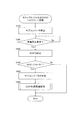
- FIG. 7 is a flowchart for explaining the flow of power generation permission determination according to the fifth embodiment.
- FIG. 1 is a diagram showing a configuration of a power supply system for a vehicle according to a first embodiment.
- FIG. 2 is a view showing a configuration of a power supply system for a vehicle according to a
- FIG. 8 is a view showing a configuration of a power supply system for a vehicle according to a sixth embodiment.
- FIG. 9 is a flowchart for explaining the flow of power generation permission determination according to the sixth embodiment.
- FIG. 10 is a flowchart for explaining the flow of SOFC stop related control according to the seventh embodiment.
- FIG. 11 is a diagram showing a configuration of a power supply system for a vehicle according to an eighth embodiment.
- FIG. 12 is a flow chart for explaining the flow of SOFC stop related control according to the eighth embodiment.
- FIG. 13 is a flowchart for explaining the flow of EAP process related control according to the eighth embodiment.
- FIG. 14 is a diagram showing a configuration of a power supply system for a vehicle according to a ninth embodiment.
- FIG. 15 is a flowchart for explaining the flow of control after termination of EAP according to the ninth embodiment.
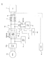
- FIG. 1 is a diagram for explaining a schematic configuration of a power supply system for a vehicle according to a first embodiment.
- the vehicle power supply system 100 includes a main battery 10 for supplying power to a traveling motor 200 of the vehicle and a SOFC (solid oxide fuel cell: solid oxide fuel cell for supplying power to the main battery 10).
- fuel cell 12 a main line 14 connecting the main battery 10 and the SOFC 12, an FC converter 16 as a first voltage converter disposed on the main line 14 to transform the output voltage of the SOFC 12, and an FC converter in the main line 14
- An FC connection relay 18 as a relay provided between the SOFC 12 and the SOFC 12, and a sub-battery 22 connected to an accessory power supply line 300 for supplying power to the vehicle or the accessory 400 of the SOFC 12.
- the traveling motor 200 is configured by a three-phase alternating current motor, receives power supply from the main battery 10 and the SOFC 12, and generates driving force of a vehicle on which the vehicle power supply system 100 is mounted.
- the traveling motor 200 functions as a generator according to the traveling state such as the operating state of a regenerative brake, for example, and supplies regenerative power to the main battery 10.
- the traveling motor 200 is provided with a motor inverter 200a that converts DC power supplied from the main battery 10 and the SOFC 12 into AC power while converting AC regenerative power generated by the traveling motor 200 into DC power. It is done.
- the main battery 10 is configured of, for example, a secondary battery such as a lithium ion battery.
- main battery 10 receives supply of electric power from an external charging device (not shown) and generated electric power of SOFC 12, and charges, while based on a request from electric motor 200, electric power being charged to the electric motor 200. Supply.
- the SOFC 12 is configured by stacking cells obtained by sandwiching an electrolyte layer formed of a solid oxide such as ceramic with an anode (fuel electrode) and a cathode (air electrode).
- the SOFC 12 receives the supply of fuel gas (hydrogen) to the fuel electrode and generates power by receiving the supply of oxidizing gas (oxygen) to the air electrode.
- the SOFC 12 in the present embodiment generates power when, for example, the charge power of the main battery 10 is insufficient for the traveling request, and the generated power is transmitted via the FC converter 16 through the main line 14 which is a power supply line. Supply to the main battery 10.
- the FC converter 16 is a DCDC converter that transforms (boosts) the power generated by the SOFC 12 and supplies it to the main battery 10 and the traveling motor 200.
- the FC converter 16 boosts the power supplied from the SOFC 12 to the main battery 10 in a state where the input-side capacitor 16a as a charging unit and the input-side capacitor 16a are charged on the side of the FC connection relay 18 (the SOFC 12 side).
- a transformer circuit 16 b constituted by circuit elements such as a coil or a transformer.
- the FC connection relay 18 is, for example, a normally open relay, and is controlled by the controller 90 in response to a request from the main battery 10 to the generated power of the SOFC 12 or the like.
- the sub battery 22 is a battery that supplies electric power to the electric component of the vehicle or the accessory 400 such as an air blower of the SOFC 12 through the accessory power supply line 300.
- the vehicle power supply system 100 of the present embodiment is configured to be able to supply the power stored in the sub-battery 22 to the input-side capacitor 16 a of the FC converter 16.
- the sub-battery 22 is connected in parallel between the FC connection relay 18 and the FC converter 16 (more specifically, the input-side capacitor 16a) in the main line 14 via the subline 24.
- a sub converter 26 as a second voltage converter is disposed in the sub line 24 to control the power supplied from the sub battery 22 to the input side capacitor 16 a.
- the sub-converter 26 is a DC-DC converter having a function of extracting power from the sub-battery 22 and charging the input-side capacitor 16 a based on a command from the controller 90.
- the power supply system 100 for vehicles is provided with the controller 90 which controls opening and closing of the FC connection relay 18.
- the controller 90 is constituted by a computer, particularly a microcomputer, provided with a central processing unit (CPU), a read only memory (ROM), a random access memory (RAM), and an input / output interface (I / O interface).
- the controller 90 is programmed to execute at least one process of the processes of the present embodiment and each of the embodiments described later.
- the controller 90 may be configured as one device, or may be divided into a plurality of devices, and each control of the present embodiment may be configured to be distributed and processed by the plurality of devices.
- the controller 90 acquires the FC output voltage detection value Vfc_d from the FC voltage sensor 30 as a fuel cell output voltage acquisition unit that detects the output voltage of the SOFC 12. Then, the controller 90 executes open / close control of the FC connection relay 18 and control of the sub converter 26 based on the FC output voltage detection value Vfc_d.
- the FC connection relay 18 is maintained in the open state.
- the FC connection relay 18 is closed and the generated power of the SOFC 12 is supplied to the main battery 10.
- the controller 90 controls the sub-converter 26 to charge the input-side capacitor 16a to a predetermined voltage, preferably with the FC connection relay 18 open.
- the voltage of the input-side capacitor 16 a will be simply referred to as “input-side capacitor voltage Vic”.
- the FC connection relay 18 can be closed, and the generation of inrush current can be suppressed.
- the sub-converter 26 is used to charge the input-side capacitor 16a. Therefore, the large FC converter 16 in which the power control to the high power system including the main battery 10 is assumed is performed while suppressing the power loss compared to the case where the difference between the output voltage of the SOFC 12 and the voltage of the main battery 10 is adjusted. The difference in voltage can be eliminated.
- the FC connection relay 18 is provided with a so-called precharge relay to close the precharge relay. It is conceivable to eliminate the potential difference between the SOFC 12 and the input side capacitor 16a. However, in this case, the SOFC 12 and the input-side capacitor 16a are energized via the precharge relay in a state where the preparation for power generation of the SOFC 12 is not completed and the output is not stable (the IV characteristic of the SOFC 12 is transient). It will be possible.
- charging of the input-side capacitor 16a by the sub-converter 26 is performed in a state where the FC connection relay 18 is opened and the conduction between the SOFC 12 and the input-side capacitor 16a is disconnected. Precharging is possible. Therefore, it is possible to cut off the conduction with the input-side capacitor 16a until the output of the SOFC 12 is stabilized, so that the input-side capacitor 16a is charged without performing the control for eliminating the potential difference fluctuation. be able to. That is, control relating to the charging can be simplified.
- the vehicle power supply system 100 connects the main battery 10 for supplying power to the traveling motor 200 of the vehicle, the SOFC 12 as a fuel cell for supplying power to at least the main battery 10, and the main battery 10 and the SOFC 12
- An FC converter 16 as a first voltage converter including a main line 14, an input-side capacitor 16 a as a charging unit disposed on the main line 14 and adjusting the output voltage of the SOFC 12, and a transformer circuit 16 b as a transformer unit
- An FC connection relay 18 as a relay provided between the FC converter 16 and the SOFC 12 in a line 14, and a sub-battery 22 connected to an accessory power supply line 300 for supplying power to the vehicle or the accessory 400 of the SOFC 12.
- the vehicle power supply system 100 is connected between the FC connection relay 18 and the input capacitor 16a in the main line 14 and serves as a second voltage converter for adjusting the power supplied from the sub battery 22 to the input capacitor 16a.
- a sub converter 26 is provided.
- the subconverter 26 is mainly used to charge the input-side capacitor 16a, the subconverter 26 is smaller in size than the large (large output) FC converter 16 in which the number of elements, wiring, and the like are complicated. it can. Therefore, compared with the case where the difference between the output voltage of SOFC 12 and the voltage of main battery 10 is adjusted using a large FC converter 16, the difference between the output voltage of SOFC 12 and the voltage of main battery 10 is eliminated while suppressing power loss. can do.
- the FC converter 16 is configured as a bidirectional converter. Has become more complicated and larger.
- the FC converter 16 can be configured as a one-way converter that boosts the voltage from the SOFC 12 toward the main battery 10, so the configuration of the FC converter 16 is also simplified. Be done. As a result, it is possible to realize the elimination of the difference between the output voltage of the SOFC 12 and the voltage of the main battery 10 while simplifying the configuration of the entire vehicle power supply system 100 more suitably.
- the vehicle power supply system 100 uses the FC voltage sensor 30 as a fuel cell output voltage acquisition unit that acquires the output voltage of the SOFC 12 and the FC output voltage detection value Vfc_d that is the acquired output voltage of the SOFC 12
- the controller 90 further includes a controller 90 that executes switching control of the FC connection relay 18 and control of the sub-converter 26.
- FC output voltage detection value Vfc_d it is possible to preferably block FC connection relay 18 at a timing at which rush current resulting from the difference between the open voltage of SOFC 12 and the voltage of main battery 10 can be suppressed. . Therefore, in a scene such as when the SOFC 12 starts up, the FC connection relay 18 can be closed at a timing when the difference between the FC output voltage detection value Vfc_d and the input-side capacitor voltage Vic becomes relatively small. It can be suitably suppressed.
- FIG. 2 is a diagram showing a configuration of a vehicular power supply system 100 in the second embodiment.
- the transformer circuit 16 b of the FC converter 16 is omitted to simplify the drawing.
- the sub-converter 26 is integrated with the FC converter 16. More specifically, the sub-converter 26 is integrated with the FC converter 16 while being connected to the main line 14 between the sub-battery 22 and the input-side capacitor 16a as in the first embodiment. Thereby, it is possible to share circuit elements and wiring used for the control substrate, the power supply substrate, etc. included in the FC converter 16 and the sub-converter 26, and the system configuration can be further simplified.
- the sub-converter 26 mainly aims to supply power to the accessory 400 and charge the input-side capacitor 16a, assumed control power is smaller than that of the FC converter 16. . Therefore, the circuit configuration is simpler and the number of parts is smaller than that of the FC converter 16. Therefore, even if sub-converter 26 is incorporated into FC converter 16, charge control to input-side capacitor 16a described in the first embodiment can be realized without complicating the configuration of existing FC converter 16. .
- the sub converter 26 is integrally formed with the FC converter 16. Thereby, it is possible to share circuit elements and wiring used for the control substrate, the power supply substrate, etc. included in the FC converter 16 and the sub-converter 26, and the system configuration can be further simplified. As a result, it contributes to downsizing of the power supply system 100 for a vehicle.
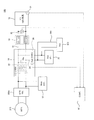
- FIG. 3 is a diagram showing the configuration of the vehicle power supply system 100 in the present embodiment.
- the FC converter 16 includes a transformer 40 as a transformer circuit 16 b between the SOFC 12 and the main battery 10. Therefore, the output voltage of the SOFC 12 is boosted by the transformer 40 and supplied to the main battery 10. More specifically, the transformer 40 is disposed on the secondary side (the main battery 10 side) of the input-side capacitor 16 a in the main line 14.
- the SOFC 12 of the present embodiment is configured such that the maximum output voltage is less than 60V. More specifically, for example, the number of stacked unit cells constituting the SOFC 12 is adjusted such that the maximum output voltage is less than 60V.
- the SOFC 12 when the maximum output voltage of the SOFC 12 is configured to be less than 60 V, the SOFC 12 can be removed from the target components of the high voltage safety request determined from the viewpoint of the safety of the vehicle.
- the voltage exceeds 60 V for safety reasons. It is required not to install voltage electrical components. However, since the maximum output voltage of the SOFC 12 of the present embodiment is less than 60 V, it does not fall under such a high voltage electrical component. Therefore, the SOFC 12 can be installed also in the front area and the rear area of the vehicle where the installation is not supposed.
- the transformer 40 of the FC converter 16 is interposed between the SOFC 12 not corresponding to the high voltage electrical component and the main battery 10 corresponding to the high voltage electrical component. Therefore, since the SOFC 12 and the main battery 10 are not directly wired, the SOFC 12 is substantially electrically isolated from the main battery 10 of the high voltage electrical component.
- the SOFC 12 can be more reliably made independent of the high voltage system including the main battery 10.
- the SOFC 12 can be installed in an arbitrary area of the vehicle including the collision area while satisfying the high voltage safety requirements, so that the freedom of the layout of the vehicle can be improved.
- the transformer (the transformer circuit 16 b) of the FC converter 16 is configured by the transformer 40.
- the SOFC 12 can be made independent of the high voltage system.
- SOFC12 is comprised so that the maximum output voltage may be less than 60V.
- the SOFC 12 can be removed from the target parts of the high voltage safety requirements defined from the viewpoint of the safety of the vehicle.
- the SOFC 12 can be made non-high voltage It is possible to cut off the direct electrical connection with the main battery 10 which is a high voltage electrical component while being a component. Therefore, the SOFC 12 can be installed in an arbitrary area of the vehicle including the collision area while satisfying the high voltage safety requirements, so that the freedom of the layout of the vehicle can be improved.
- the SOFC 12 having a high operating temperature can be separated from the other components as much as possible.
- the transformer 40 is provided to the FC converter 16 having a configuration in which the sub-converter 26 is integrated is described.
- the transformer 40 may be provided in the FC converter 16.
- the fourth embodiment will be described below.
- the same components as those in the first to third embodiments are denoted by the same reference numerals, and the detailed description thereof will be omitted.
- startup relay closing control the closing control of the FC connection relay 18 executed in the scene of activation of the SOFC 12 (hereinafter, “startup relay closing control”) Will also be described.
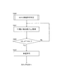
- FIG. 4 is a flowchart for explaining the flow of start-up relay closing control in the present embodiment.
- step S110 the controller 90 determines whether the SOFC 12 is activated. More specifically, the controller 90 determines that the SOFC 12 is activated when detecting a power generation request to the SOFC 12 when, for example, the remaining charge (SOC) of the main battery 10 falls below a predetermined value. Then, when it is determined that the SOFC 12 is activated, the controller 90 performs the process of step S120.
- SOC remaining charge
- step S120 the controller 90 charges the input-side capacitor 16a of the FC converter 16 with the FC connection relay 18 open. Specifically, the controller 90 controls the sub-converter 26 to charge the input capacitor 16a such that the input capacitor voltage Vic approaches the FC output voltage detection value Vfc_d. That is, the input side capacitor voltage Vic is brought close to the open circuit voltage of the SOFC 12 to suppress the voltage difference between the input side capacitor voltage Vic and the open circuit voltage of the SOFC 12.
- step S130 the controller 90 determines that the absolute value of the difference between the FC output voltage detection value Vfc_d and the input-side capacitor voltage Vic (hereinafter, "FC-also described as capacitor voltage difference absolute value
- is less than or equal to threshold voltage difference ⁇ Vth.
- step S140 the controller 90 closes the FC connection relay 18.
- step S120 to step S140 the FC connection relay 18 is closed in a state where the voltage difference between the input side capacitor voltage Vic and the open circuit voltage of the SOFC 12 is relatively small. Therefore, it is possible to suppress the occurrence of inrush current when the FC connection relay 18 is closed.
- the controller 90 determines whether the SOFC 12 is activated (step S110 in FIG. 4), and when it is determined that the SOFC 12 is activated, controls the subconverter 26 to To charge the input capacitor 16a (step S120 in FIG. 4). Then, the controller 90 closes the FC connection relay 18 after charging the input-side capacitor 16a (step S140 in FIG. 4).
- the input capacitor 16a when the SOFC 12 is started, the input capacitor 16a can be charged in a state where the FC connection relay 18 is open, and the input capacitor voltage Vic can be brought close to the open voltage of the SOFC 12. Therefore, the voltage difference between the input-side capacitor voltage Vic and the open circuit voltage of the SOFC 12 can be reduced, and the FC connection relay 18 can be closed in the state where the voltage difference is reduced. Generation of inrush current can be suppressed more reliably.
- the controller 90 sets the FC-capacitor voltage difference absolute value
- ⁇ Vfc_d as the difference between the input-side capacitor voltage Vic, which is the voltage of the input-side capacitor 16a, and the FC output voltage detection value Vfc_d. Is charged to the input-side capacitor 16a such that the threshold voltage difference .DELTA.Vth is equal to or smaller than -ic.vertline. (Steps S120 and S130 in FIG. 4).
- the controller 90 detects that there is a power generation request to the SOFC 12 when it determines that the SOFC 12 is activated, and charges the input-side capacitor 16a.
- the SOC of the main battery 10 is monitored to detect the prediction that the SOFC 12 needs to be started, and when the prediction is detected, before actually entering into the SOFC 12 start processing (detection of power generation request)
- the input capacitor 16a may be charged before the above.
- FIG. 5 is a flowchart for explaining the flow of start-up relay closing control in the present modification.
- the same step number is attached
- the controller 90 determines that the FC-capacitor voltage difference absolute value
- step S131 the controller 90 determines whether the FC-capacitor voltage difference ⁇ Vfc_d-ic obtained by subtracting the input-side capacitor voltage Vic from the FC output voltage detection value Vfc_d is 0 or more. That is, it is determined whether the FC output voltage detection value Vfc_d is equal to or higher than the input-side capacitor voltage Vic.
- the controller 90 determines that the FC output voltage detection value Vfc_d is equal to or higher than the input-side capacitor voltage Vic, the controller 90 closes the FC connection relay 18 in step S140.
- controller 90 determines in step S131 that FC output voltage detection value Vfc_d is less than input-side capacitor voltage Vic
- controller 90 discharges the power stored in input-side capacitor 16a in step S132.
- the controller 90 controls the sub-converter 26 to discharge the charging power from the input side capacitor 16 a to a discharge circuit built in the sub-converter 26 (not shown) or configured separately from the sub-converter 26.
- the FC connection relay 18 since the FC connection relay 18 is closed in a state where the output voltage of the SOFC 12 is higher than the input side capacitor voltage Vic, the current flowing at the time of the closing is directed from the SOFC 12 to the direction of the input side capacitor 16a. can do. Therefore, it is possible to suppress the flow of current from the input side capacitor 16a to the SOFC 12 when the FC connection relay 18 is closed.
- sub-converter 26 basically supplies power to input-side capacitor 16a under charge control in which FC-capacitor voltage difference absolute value
- the power is not supplied from the input side capacitor 16 a in the direction of the sub-converter 26). That is, basically, it is considered that the input-side capacitor voltage Vic is lower than the FC output voltage detection value Vfc_d during the charge control.
- start-up relay closing control is started in a state where the input side capacitor 16a has already been charged to some extent in a scene such as at the time of restarting after a short time stop of the SOFC 12.
- controller 90 controls sub-converter 26 to charge input-side capacitor 16a such that input-side capacitor voltage Vic is equal to or lower than FC output voltage detection value Vfc_d (see FIG. Steps S131 and S132 in FIG. 5).
- control for discharging the input capacitor 16a has been described as an example of the control for making the input capacitor voltage Vic equal to or lower than the output voltage of the SOFC 12.
- control to make the input-side capacitor voltage Vic other than this lower than the output voltage of the SOFC 12 may be adopted.
- the target value of the input-side capacitor voltage Vic is set lower by a predetermined margin with respect to the FC output voltage detection value Vfc_d within a range where FC-capacitor voltage difference absolute value
- the input-side capacitor voltage Vic may be maintained at or below the output voltage of the SOFC 12.
- the fifth embodiment will be described below.
- the same components as those in the first to fourth embodiments are denoted by the same reference numerals, and the detailed description thereof will be omitted.
- an aspect different from that of the fourth embodiment will be described with respect to the start-up relay closing control.
- the present embodiment will be described on the premise that it is based on the start-up relay closing control of the fourth embodiment shown in FIG. 4 from the viewpoint of simplifying the description, the fifth to ninth embodiments are implemented. In any of the embodiments, the start relay closing control according to the modification of the fourth embodiment shown in FIG. 5 may be based.
- FIG. 6 is a flowchart for explaining the flow of start-up relay closing control in the present embodiment.
- step S210 the controller 90 determines whether the SOFC 12 is activated as in the fourth embodiment.
- the controller 90 determines that the SOFC 12 is to be activated, the controller 90 performs the process of step S220.
- step S220 the controller 90 performs power generation permission determination to determine whether the power generation of the SOFC 12 is permitted. Specifically, in the start-up process of the SOFC 12, a warm-up process of heating the SOFC 12 with a start-up combustor or the like (not shown) is performed, and the temperature of the SOFC 12 gradually rises to a predetermined operating temperature (for example, 700.degree. Approaching 900 ° C). The SOFC 12 operates with the required power generation characteristics by reaching such an appropriate operating temperature.
- a predetermined operating temperature for example, 700.degree. Approaching 900 ° C.
- the warm-up process when the warm-up process is completed, it is determined that the power generation of the SOFC 12 is permitted. On the other hand, if the warm-up process of the SOFC 12 is not completed and the SOFC 12 does not reach the above-mentioned suitable operating temperature, there is a possibility that the SOFC 12 does not reach the required power generation characteristics. It is judged that the generation of electricity is not permitted.
- the power generation characteristic of the SOFC 12 is correlated with the magnitude of the open circuit voltage of the SOFC 12. That is, as the open circuit voltage of the SOFC 12 is larger, the power generation characteristic of the SOFC 12 is higher. Therefore, in the present embodiment, in the state where the FC connection relay 18 is open, the power generation permission of the SOFC 12 is determined based on the FC output voltage detection value Vfc_d as the open voltage of the SOFC 12.
- the content of specific power generation permission determination will be described.
- FIG. 7 is a flowchart showing the process of determining whether the power generation of the SOFC 12 is permitted in the present embodiment.
- step S221 the controller 90 acquires an FC output voltage detection value Vfc_d from the FC voltage sensor 30.
- step S222 the controller 90 determines whether or not the FC output voltage detection value Vfc_d has reached the threshold voltage Vth1, that is, whether or not Vfc_d ⁇ Vth1.
- the threshold voltage Vth1 is suitably set as a reference for determining that the FC output voltage detection value Vfc_d can exhibit the normally required power generation characteristic of the SOFC 12 (determine that the warm-up process has ended).
- the controller 90 determines that the FC output voltage detection value Vfc_d is equal to or higher than the threshold voltage Vth1, the controller 90 determines that the power generation of the SOFC 12 is permitted, and proceeds to step S230.
- controller 90 passes through the processing of step S230, step S240 and step S250 similarly to the processing of step S120, step S130 and step S140 of FIG. 5 according to the fourth embodiment. Block the
- the FC connection relay 18 can be closed in a state where the power generation of the SOFC 12 is permitted and the power generation characteristics are stable. That is, the FC connection relay 18 can be closed in a region where the change in output voltage is relatively small with respect to the current drawn from the SOFC 12.
- the FC connection relay 18 when the FC connection relay 18 is closed in a state where the output voltage of the SOFC 12 is equal to or higher than the input-side capacitor voltage Vic, the current flows from the SOFC 12 to the input-side capacitor 16a, whereby the output voltage of the SOFC 12 is large.
- the controller 90 determines whether the power generation of the SOFC 12 is permitted when the SOFC 12 is activated (step S220 in FIG. 6), and determines that the power generation of the SOFC 12 is permitted. Then, the sub converter 26 is controlled to charge the input-side capacitor 16a (step S230 in FIG. 6), and the FC connection relay 18 is closed after the input-side capacitor 16a is charged (step S250 in FIG. 6). In particular, the controller 90 determines whether the power generation of the SOFC 12 is permitted based on whether the FC output voltage detection value Vfc_d is equal to or higher than the threshold voltage Vth1 (step S222 in FIG. 7). When the detected value Vfc_d is equal to or higher than the threshold voltage Vth1, it is determined that the power generation of the SOFC 12 is permitted (step S223 in FIG. 7).
- the power generation of the SOFC 12 is permitted, and a state in which the power generation characteristics are stable can be detected more reliably, and the FC connection relay 18 can be closed at the stable timing. That is, the FC connection relay 18 can be closed in a region where the change in output voltage is relatively small with respect to the current drawn from the SOFC 12. Thereby, when the current is extracted from the SOFC 12 for supply to the main battery 10 or the like after the closing of the FC connection relay 18, hunting of the voltage caused by the fluctuation of the output voltage of the SOFC 12 can be suppressed.
- the FC connection relay 18 will not be blocked. Therefore, it is possible to more reliably detect the case where the above-mentioned voltage hunting is concerned because the power generation of the SOFC 12 is not stabilized due to these other factors, and the FC connection relay 18 is not blocked. As a result, generation of inrush current when the FC connection relay 18 is blocked can be suppressed more reliably.
- the controller 90 determines whether the power generation of the SOFC 12 is permitted based on the FC output voltage detection value Vfc_d.
- the controller 90 applies a relatively small predetermined load to the SOFC 12, and changes the output current of the SOFC 12 by the load, and the power generation characteristic of the SOFC 12 based on the change of the FC output voltage detection value Vfc_d before and after applying the load. If the estimated power generation characteristic reaches a predetermined power generation characteristic threshold, it may be determined that power generation is permitted.
- the sixth embodiment will be described below.
- the same components as those in the first to fifth embodiments are denoted by the same reference numerals, and the detailed description thereof will be omitted.
- the power generation permission determination of the SOFC 12 in the block control of the FC connection relay 18 is performed based on the temperature (stack temperature Ts) of the SOFC 12 instead of the FC output voltage detection value Vfc_d of the fifth embodiment.
- FIG. 8 is a diagram showing a configuration of a vehicle power supply system 100 in the present embodiment.
- the power supply system 100 for a vehicle is provided with a stack temperature sensor 32 for detecting the temperature of the SOFC 12 based on the system configuration (see FIG. 3) described in the third embodiment. There is. Then, the stack temperature detection value Ts_d detected by the stack temperature sensor 32 is appropriately transmitted to the controller 90.
- the flow of the start-up relay closing control in this embodiment is the same as the flow shown in FIG. 6 according to the fifth embodiment, so only the part of the power generation permission determination that differs from the fifth embodiment will be described.
- FIG. 9 is a flowchart showing the process of determining whether the power generation of the SOFC 12 is permitted in the present embodiment.
- step S221 ′ the controller 90 acquires the stack temperature detection value Ts_d from the stack temperature sensor 32.
- step S222 ' the controller 90 determines whether or not the stack temperature detection value Ts_d has reached the first threshold temperature Tth1, that is, whether or not Ts_d ⁇ Tth1.
- the first threshold temperature Tth1 is determined from the viewpoint of whether the stack temperature detection value Ts_d is a temperature at which the power generation characteristic of the SOFC 12 normally required is obtained.
- the controller 90 determines that the power generation of the SOFC 12 is permitted in step S223 ′, and the step of FIG. 6 according to the fifth embodiment. After the processing of S230, step S240, and step S250, the FC connection relay 18 is closed.
- the present embodiment it is possible to more reliably detect that the stack temperature Ts has reached the predetermined operating temperature, and to close the FC connection relay 18.
- the increase in the stack temperature Ts accompanying the progress of the warm-up process correlates with the improvement of the power generation characteristic of the SOFC 12. Therefore, by determining whether the power generation of the SOFC 12 is permitted based on the stack temperature detection value Ts_d, the time when the power generation characteristic of the SOFC 12 becomes the required characteristic is suitably detected, and the FC connection relay 18 is Can be closed.
- the vehicle power supply system 100 further includes a stack temperature sensor 32 that is a fuel cell temperature acquisition unit that acquires a stack temperature detection value Ts_d as the temperature of the SOFC 12. Then, the controller 90 determines whether the power generation of the SOFC 12 is permitted based on whether the stack temperature detection value Ts_d is equal to or higher than the first threshold temperature Tth1 (step S222 ′ in FIG. 9). When the temperature is equal to or higher than the first threshold temperature Tth1, it is determined that the power generation of the SOFC 12 is permitted (step S223 ′ in FIG. 9).
- the FC connection relay 18 can be more reliably closed at a timing when the change in output voltage is relatively small with respect to the current drawn from the SOFC 12.
- the above-described hunting of the voltage caused by the fluctuation of the output voltage of the SOFC 12 is suppressed more preferably. be able to.
- the stack temperature Ts can be regarded as a parameter representing the power generation characteristic of the SOFC 12 in fact.
- the power generation characteristics of the SOFC 12 can be grasped with high accuracy, and the FC connection relay 18 can be closed at an appropriate timing. As a result, generation of inrush current when the FC connection relay 18 is blocked can be suppressed more reliably.
- the stack temperature sensor 32 for detecting the temperature is provided in the SOFC 12 based on the system configuration (see FIG. 3) described in the third embodiment, and the block control of the FC connection relay 18 and the related control
- the example of performing the power generation permission determination in the block control has been described.
- the present invention is not limited to this, and based on the system configuration (see FIG. 1) described in the first embodiment (see FIG. 1) and the system configuration described in the second embodiment (see FIG. 2)
- a sensor 32 may be provided to perform the block control of the FC connection relay 18 and the power generation permission determination in the block control.
- the power generation permission determination may be performed using the output voltage of the SOFC 12 (the FC output voltage detection value Vfc_d). For example, when both the stack temperature detection value Ts_d and the FC output voltage detection value Vfc_d become equal to or higher than the first threshold temperature Tth1 and the threshold voltage Vth1, respectively, it is determined that the power generation of the SOFC 12 is permitted. Also good.
- the stack temperature Ts can usually be a parameter representing the power generation characteristic of the SOFC 12.
- the stack temperature detection value Ts_d is equal to or higher than the first threshold temperature Tth1 because the warm-up processing itself is normally performed or the stoichiometric ratio of the fuel and air supplied to the SOFC 12 is not appropriate.
- the desired power generation characteristics can not be obtained. In this case, since the power generation characteristic is actually low and the preparation of the SOFC 12 is not sufficient, it is preferable that it is judged that the power generation is not permitted.
- the stack temperature detection value Ts_d is equal to or higher than the first threshold temperature Tth1 by performing the power generation permission determination of the SOFC 12 based on both the stack temperature detection value Ts_d and the FC output voltage detection value Vfc_d as described above. Even if there is, since the FC output voltage detection value Vfc_d does not become equal to or higher than the threshold voltage Vth1, it is possible to more reliably detect a state where the above-described desired power generation characteristic is not obtained and to judge that power generation is not permitted. .
- the open circuit voltage of the SOFC 12 becomes higher than expected due to factors such as individual differences of unit cells constituting the SOFC 12, and the FC output voltage detection value Vfc_d is not obtained even though the SOFC 12 has not reached desired power generation characteristics. Is assumed to be equal to or higher than the threshold voltage Vth1. In this case, since the warm-up process is not actually completed, it can be determined that the stack temperature detection value Ts_d does not become equal to or higher than the first threshold temperature Tth1 and that power generation is not permitted.
- blockade of the FC connection relay 18 can be performed more reliably by suppressing the generation of the inrush current by determining whether the SOFC 12 is allowed to generate power based on both the stack temperature detection value Ts_d and the FC output voltage detection value Vfc_d. can do.
- the seventh embodiment will be described below.
- the same components as those in the first to sixth embodiments are denoted by the same reference numerals, and the detailed description thereof will be omitted.
- the FC connection relay 18 is blocked by the start-up relay blocking control (see FIGS. 4 to 6) described in the fourth to sixth embodiments.
- the start-up relay blocking control see FIGS. 4 to 6 described in the fourth to sixth embodiments.
- FIG. 10 is a flowchart showing the flow of SOFC stop related control in the present embodiment.
- step S140 when the FC connection relay 18 is closed in step S140 (see FIG. 4) or step S250 (see FIG. 6), the controller 90 executes SOFC stop related control after step S310.
- step S310 the controller 90 stops the subconverter 26.
- the controller 90 deactivates the sub-converter 26 substantially simultaneously with (in response to the occlusion) the occlusion of the FC connection relay 18.
- the sub-converter 26 is used to control charging of the input-side capacitor 16a when the SOFC 12 is started, and basically, the need to operate the SOFC 12 during operation is low. Therefore, as in the present embodiment, by stopping the sub-converter 26 promptly in conjunction with the closing of the FC connection relay 18, it is possible to suppress the power consumption due to continuing the useless operation of the sub-converter 26.
- step S320 the controller 90 determines whether or not there is a power generation stop request of the SOFC 12 after stopping the sub-converter 26 as described above. Specifically, the controller 90 determines that there is a power generation stop request by detecting an operation of a predetermined SOFC stop operation switch (not shown), for example.
- step S330 the controller 90 stops the SOFC 12. Specifically, the controller 90 issues, for example, a command to stop the SOFC system provided with a fuel system or an air system actuator for generating the SOFC 12. According to this command, the fuel supply to the SOFC 12 is stopped, and a stop sequence including the cooling process of the SOFC 12 is executed.
- controller 90 reactivates sub-converter 26. This is for controlling the applied voltage of the EAP process by the sub-converter 26 in relation to the later-described EAP (Electric Anode Protection) process performed to suppress the oxidation deterioration of the anode catalyst at the time of stopping the SOFC 12.
- EAP Electro Anode Protection
- step S350 the controller 90 executes EAP processing as fuel cell protection processing.
- the EAP treatment is a protective voltage of a desired magnitude that is a voltage opposite to a voltage obtained by power generation of the SOFC 12
- This is a process of supplying a current of a predetermined magnitude (hereinafter also referred to as “EAP current”) to the SOFC 12 so as to be applied to the SOFC 12.
- the sub battery 22 is used as a power supply for EAP processing, and the EAP current is adjusted by the sub converter 26. That is, in the present embodiment, the controller 90 controls the sub-converter 26 to adjust the power extracted from the sub-battery 22 to control the EAP current to a desired magnitude.
- the FC connection relay 18 when the EAP processing is performed, the FC connection relay 18 is in a closed state, so that it is possible to supply the EAP current from the sub-battery 22 to the SOFC 12.
- the sub-converter 26 of this embodiment is smaller than the FC converter 16 because it is used to execute the above-described EAP processing in addition to the charging of the input-side capacitor 16a at the time of startup of the SOFC 12 described in the fourth embodiment. It is desirable that the output be slightly larger than in the case where only the charge control to the input side capacitor 16a is performed while the output is made.
- step S360 the controller 90 determines whether the stack temperature detection value Ts_d obtained by the stack temperature sensor 32 is less than or equal to a predetermined second threshold temperature Tth2.
- the reaction in which the catalyst in the anode electrode is oxidized does not occur below the oxidative degradation point (for example, a temperature between 400 ° C. and 500 ° C.) It has been known. That is, the oxidative degradation point is the lower limit of the temperature at which oxidative degradation of the anode occurs. Therefore, when the temperature of the SOFC 12 decreases due to the cooling process included in the SOFC 12 stop sequence, the EAP process can be stopped if the temperature is lower. Therefore, in the present embodiment, it is determined whether the stack temperature detection value Ts_d is equal to or lower than the second threshold temperature Tth2 as the determination as to whether or not the EAP processing is to be stopped.
- the stack temperature detection value Ts_d is equal to or lower than the second threshold temperature Tth2 as the determination as to whether or not the EAP processing is to be stopped.
- the second threshold temperature Tth2 it is preferable to set the second threshold temperature Tth2 to a temperature at or near the oxidation deterioration point.
- the controller 90 determines that the stack temperature detection value Ts_d is equal to or lower than the second threshold temperature Tth2, the controller 90 ends the EAP processing in step S370. Specifically, the controller 90 controls the sub-converter 26 to set the EAP current to zero.
- the controller 90 appropriately opens the FC connection relay 18 and stops the sub-converter 26 again.
- the controller 90 stops the sub-converter 26 (step S310 in FIG. 10).
- the sub-converter 26 can be promptly stopped in conjunction with the closing of the FC connection relay 18, and power consumption due to continuing the useless operation of the sub-converter 26 can be suppressed.
- the controller 90 determines whether there is a power generation stop request for the SOFC 12 (step S320 in FIG. 10). If so, the power generation of the SOFC 12 is stopped (step S330 in FIG. 10), and the subconverter 26 is reactivated while the FC connection relay 18 is closed (step S340 in FIG. 10). 26 is controlled to execute EAP processing as fuel cell protection processing for applying a predetermined voltage from the sub-battery 22 to the SOFC 12 (step S350 in FIG. 10).
- the FC connection relay 18 is in a closed state, so that it is possible to supply the EAP current from the sub-battery 22 to the SOFC 12. And, by supplying the EAP current from the sub-battery 22 to the SOFC 12 using the sub-converter 26, the EAP processing can be executed without providing another converter or battery for performing the EAP processing. .
- the existing system configuration can be simplified, and the relay at startup can be performed. Both blocking control and EAP processing at the time of stopping can be realized.
- the system configuration can be further simplified as compared with the existing system in which the FC converter 16 is bidirectionalized to execute EAP processing.
- the vehicle power supply system 100 includes a stack temperature sensor 32 (see FIG. 8) as a temperature acquisition unit of a fuel cell that acquires a stack temperature detection value Ts_d that is the temperature of the SOFC 12.
- a stack temperature sensor 32 see FIG. 8 as a temperature acquisition unit of a fuel cell that acquires a stack temperature detection value Ts_d that is the temperature of the SOFC 12.
- the EAP processing can be ended promptly. Therefore, the power consumption of the EAP processing can be suppressed.
- the second threshold temperature Tth2 is set to an oxidation deterioration point as a temperature at which oxidation deterioration in the anode electrode of the SOFC 12 occurs.
- the EAP processing can be terminated at a timing when the stack temperature Ts falls below an oxidation deterioration point at which the catalyst oxidation in the anode electrode theoretically does not occur. That is, since the EAP processing can be terminated at a more appropriate timing, the power consumption of the EAP processing can be suppressed, and the effect of suppressing the oxidation deterioration due to the EAP processing can be more reliably exhibited.
- the sub-converter 26 is stopped during the operation of the SOFC 12 (see step S310 in FIG. 10).
- the subconverter 26 may be kept operating while the SOFC 12 is operating.
- SOFC stop related control in that case is the process of step S310 (stop of the subconverter 26) and the process of step S340 (reconversion of the subconverter 26) to the SOFC stop related control of FIG. 10 described in this embodiment. It is similar except that the operation is removed.
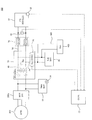
- FIG. 11 is a diagram showing a configuration of a vehicular power supply system 100 in the present embodiment.
- this vehicle power supply system 100 is an SOC sensor for detecting the charge amount (SOC) of the main battery 10 based on the system configuration (see FIG. 3) described in the third embodiment. 34 are provided.
- the SOC sensor 34 detects, for example, the voltage and charge / discharge current of the main battery 10, and calculates the charge amount of the main battery 10 from the integrated value of the voltage and current. Then, the charge amount detection value (hereinafter, referred to as “charge amount detection value SOC_d”) detected by the SOC sensor 34 is appropriately transmitted to the controller 90.
- charge amount detection value SOC_d the charge amount detection value detected by the SOC sensor 34 is appropriately transmitted to the controller 90.
- FIG. 12 is a flowchart showing the flow of SOFC stop related control in the present embodiment.
- step S410 the controller 90 executes the process of step S410 and subsequent steps. Note that each process from step S410 to step S430 shown in the figure is the same as each process from step S310 to step S330 of the seventh embodiment, and thus detailed description will be omitted.
- step S430 the controller 90 determines in step S440 whether or not the charge amount detection value SOC_d obtained by the SOC sensor 34 exceeds a predetermined first charge amount threshold ⁇ th1. .
- the main battery 10 sufficiently charged to such an extent that the power required for the traveling of the vehicle is not short for a predetermined period of time even if the SOFC 12 is stopped? It is a threshold defined from the viewpoint of whether or not. That is, if it is assumed that the main battery 10 is charged with sufficient power to drive for the predetermined time, it is considered that the time until the power generation request for the SOFC 12 is issued again becomes longer. Is expected to last long. On the other hand, when the power of the main battery 10 is insufficient for the power required for traveling of the vehicle for a predetermined time, it is considered that the time until the second power generation request to the SOFC 12 is issued becomes short.
- the power of the main battery 10 is sufficient for the power required to drive the vehicle for a predetermined period of time, it is predicted that the power generation stop state of the SOFC 12 will continue for a long time.
- the supply stop time will also be longer.
- the reduction of the fuel gas partial pressure in the anode proceeds and the inside of the anode is more likely to become an oxidizing atmosphere. Therefore, in this case, since it is highly necessary to execute the EAP process to suppress the oxidation degradation of the anode catalyst, the EAP process is performed (after “Yes” in step S440).
- the controller 90 determines that the charge amount detection value SOC_d is equal to or less than the first charge amount threshold ⁇ th1, the controller 90 ends the present SOFC stop related control. On the other hand, when the controller 90 determines that the detected charge amount SOC_d exceeds the first charge amount threshold ⁇ th1, the controller 90 executes the process of step S450.
- step S450 controller 90 reactivates subconverter 26. Then, the controller 90 executes EAP process related control in the subsequent step S460.
- FIG. 13 is a flowchart showing the details of EAP process related control.
- step S461 the controller 90 starts EAP processing.
- step S462 the controller 90 determines whether the stack temperature detection value Ts_d is equal to or lower than a second threshold temperature Tth2.
- the controller 90 ends the EAP process as in the seventh embodiment (step S465).
- step S463 when the controller 90 determines that the stack temperature detection value Ts_d exceeds the second threshold temperature Tth2, the controller 90 executes the determination process of step S463.
- step S463 the controller 90 determines whether there is another power generation request for the SOFC 12. Then, if it is determined that the power generation request for the SOFC 12 is made again, the controller 90 executes the determination processing of step S464.
- step S464 the controller 90 determines whether fuel supply to the SOFC 12 has been started. That is, the controller 90 determines whether fuel supply to the SOFC 12 is started at the stage where the start-up process of the SOFC 12 is being performed based on the second power generation request.
- step S465 ends the EAP processing. That is, when the fuel supply to the SOFC 12 is started, the oxidizing atmosphere in the anode electrode is eliminated by the fuel supply, and the oxidation deterioration of the anode electrode catalyst does not substantially occur, so the EAP processing is ended.
- step S463 On the premise that the stack temperature detection value Ts_d is not less than or equal to the second threshold temperature Tth2 (“No” in step S462), the process in step S463 is repeated. In the determination of whether or not there is a power generation request, and in the determination of whether or not the fuel supply to the SOFC 12 is started in step S464, if at least one of them is negative, the EAP processing is continued. It becomes.
- EAP is started when fuel supply is started based on the second SOFC 12 start request. Since the process is stopped, it is possible to suppress the power consumption by continuing the EAP process unnecessarily.
- the vehicle power supply system 100 further includes an SOC sensor 34 (FIG. 11) as a charge amount acquisition unit that acquires the charge amount of the main battery 10. Then, after stopping the sub-converter 26 (step S410 in FIG. 12), the controller 90 determines whether there is a power generation stop request for the SOFC 12 (step S420 in FIG. 12). If so, the power generation of the SOFC 12 is stopped (step S430 in FIG.
- step S460 applying a predetermined voltage from the sub battery 22 to the SOFC 12 by controlling the reactivated sub converter 26 It performs EAP process that (step S460 in FIG. 12).
- the FC connection relay 18 is in a closed state, so that it is possible to supply the EAP current from the sub-battery 22 to the SOFC 12. And, by supplying the EAP current from the sub-battery 22 to the SOFC 12 using the sub-converter 26, the EAP processing can be executed without providing another converter or battery for performing the EAP processing. .
- the sub-converter 26 when the detected charge amount SOC_d of the main battery 10 exceeds the first charge amount threshold ⁇ th1, the sub-converter 26 is reactivated to execute the EAP process. That is, when the power of the main battery 10 is sufficient for the power required for traveling the vehicle for the predetermined time, the EAP processing is performed.
- the stop time of the SOFC 12 is short, and the anode electrode is short enough to cause oxidation deterioration of the anode catalyst.
- the decrease in fuel gas partial pressure will not progress. Therefore, in the present embodiment, it is possible to appropriately determine this situation and not to execute the EAP process. Therefore, power consumption can be reduced by not executing EAP processing as much as possible.
- the travel time of the vehicle is set or predicted, and the vehicle requests while the SOFC 12 is stopped based on the set or predicted travel time of the vehicle. It is also possible to calculate the predicted value of the power consumption to be performed, and to determine the first charge amount threshold ⁇ th1, which is a criterion for determining whether or not to perform the EAP process, based on the predicted value of the power consumption.
- step S464 in FIG. 13 the EAP processing is ended (step S465 in FIG. 13).
- the ninth embodiment will be described below.
- the same components as those in the first to eighth embodiments are denoted by the same reference numerals, and the detailed description thereof will be omitted.
- control after EAP termination after termination of the EAP processing described in step S370 of FIG. 10 or step S490 of FIG. 12 will be described.
- FIG. 14 is a diagram showing a configuration of a vehicle power supply system 100 in the present embodiment.
- the power supply system 100 for a vehicle is provided with the stack temperature sensor 32 and the SOC sensor 34 in the system configuration (see FIG. 2) described in the second embodiment, and the output of the SOFC 12 is 60 V or more
- the discharge circuit 26 a is incorporated in the sub converter 26.
- the discharge circuit 26 a discharges the charging power of the input side capacitor 16 a in response to a command from the controller 90.
- FIG. 15 is a flow chart showing the flow of control after the end of EAP in the present embodiment.
- step S370 when the FC connection relay 18 is closed in step S370 (see FIG. 10) or step S490 (see FIG. 12), the controller 90 executes control after the end of EAP in step S510 and thereafter.
- step S510 the controller 90 controls the sub-converter 26 to discharge the charging power of the input-side capacitor 16a by the discharging circuit 26a. Thereby, the input side voltage of the FC converter 16 can be reduced more reliably.
- the output of the SOFC 12 is 60 V or more, it is desirable to quickly reduce the input side voltage of the FC converter 16 when the vehicle or the SOFC 12 is stopped. Therefore, in the present embodiment, by discharging the charging power of the input-side capacitor 16a by the discharging circuit 26a, the above-described safety requirement can be more preferably satisfied.
- the controller 90 opens the FC connection relay 18 in step S520.
- step S530 controller 90 stops sub-converter 26 again.
- the sub-converter 26 includes a discharge circuit 26a (see FIG. 14). Then, when the EAP processing is completed, the controller 90 causes the discharging circuit 26 a of the sub-converter 26 to discharge the power charged in the input-side capacitor 16 a of the FC converter 16 while closing the FC connection relay 18 (FIG. Step S510) When the power of the input side capacitor 16a is discharged, the FC connection relay 18 is opened (Step S520 in FIG. 15), and the sub-converter 26 is stopped (Step S530 in FIG. 15).
- the discharge circuit 26 a that discharges the input-side capacitor 16 a is provided in the sub-converter 26 that can be configured smaller than the FC converter 16. Therefore, for example, as compared with the case where the large-sized FC converter 16 is a bidirectional converter and the input-side capacitor 16a is discharged by the FC converter 16, power consumption by the operation of the converter can be reduced and the circuit configuration is simplified. can do.
- the discharge circuit 26a is incorporated in the sub-converter 26 based on the configuration of the vehicle power supply system 100 shown in FIG.
- the present invention is not limited to this, and the discharge circuit 26a may be incorporated in the sub-converter 26 based on the configuration of the vehicle power supply system 100 shown in FIG. 1, FIG. 3, FIG.
- each above-mentioned embodiment showed only a part of application example of the present invention, and limited the technical scope of the present invention to the concrete composition of each above-mentioned embodiment. It is not the purpose to do.
- the configuration of vehicle power supply system 100 shown in FIGS. 1 to 3, 8, 11, and 14 is merely an example of a specific embodiment that can realize the present invention, and is not necessarily limited to these configurations. It is not a thing. That is, the configuration of the vehicular power supply system 100 can be appropriately modified within the scope of the subject matter of the present invention.
- the charging portion of the sub-converter 26 is configured by the input-side capacitor 16a.
- the charging unit may be configured by any other circuit element or circuit configuration that can be conceived by those skilled in the art other than the capacitor, as long as it can adjust the input side voltage of sub converter 26 according to the output voltage of SOFC 12. It is good.
- the present invention can be appropriately applied to a vehicle power supply system provided with a fuel cell of a solid polymer type other than SOFC 12, a fuel cell stack, or a laminated fuel cell in which the fuel cells are stacked.
- the above embodiments can be combined as appropriate.
- the system configuration of the vehicle power supply system 100 described in the first to third embodiments, the startup relay closing control described in the fourth to sixth embodiments, the SOFC described in the seventh and eighth embodiments can be combined with each other as appropriate.
- ⁇ Vfc_d-ic An example of closing the FC connection relay 18 when the difference ⁇ Vth or less is described.
- the block determination of the FC connection relay 18 may be applied based on whether or not it is not.
Abstract
A power source system for a vehicle is provided which comprises: a main battery which supplies power to a traction motor of the vehicle; a fuel cell which supplies power to at least the main battery; a main line which connects the main battery and the fuel cell; a first voltage transformer which is arranged on the main line and which comprises a charging unit and a transformer unit for adjusting the output voltage of the fuel cell; a relay which is provided on the main line between the charging unit and the fuel cell; and a sub battery which is connected to an auxiliary device power supply line for supplying power to the vehicle or an auxiliary device of the fuel cell. The vehicle power source system is provided with a second voltage transformer which is connected on the main line between the relay and the charging unit and which adjusts power supplied from the sub battery to the charging unit.
Description
この発明は、特に、燃料電池を搭載した車両に用いられる車両用電源システムに関する。
The present invention particularly relates to a vehicle power supply system used for a vehicle equipped with a fuel cell.
燃料電池を搭載した車両用の電源システムは、車両の走行モータに電力を供給するメインバッテリと、車両や燃料電池の補機類に電力を供給するサブバッテリと、有している。メインバッテリと燃料電池の間を接続するメインラインには、電圧変換器としてのDCDCコンバータが設けられる。このDCDCコンバータは、燃料電池の電圧を昇圧制御してメインバッテリが配置されている強電系に供給する。
A power supply system for a vehicle equipped with a fuel cell includes a main battery for supplying power to a traveling motor of the vehicle and a sub-battery for supplying power to accessories of the vehicle and the fuel cell. The main line connecting the main battery and the fuel cell is provided with a DCDC converter as a voltage converter. This DCDC converter boosts and controls the voltage of the fuel cell and supplies it to the high power system in which the main battery is disposed.
このような車両用電源システムでは、DCDCコンバータと燃料電池の間にリレーが設けられている。このリレーは、燃料電池の起動時などにおいて閉塞され、燃料電池からDCDCコンバータを介してメインバッテリに電力が供給可能な状態となる。
In such a vehicle power supply system, a relay is provided between the DCDC converter and the fuel cell. This relay is closed at the time of start-up of the fuel cell or the like, and power can be supplied from the fuel cell to the main battery via the DCDC converter.
ここで、上記リレーの閉塞時においては、メインバッテリ側の強電系と燃料電池との間の電圧差に起因して突入電流が発生する可能性がある。このような突入電流を抑制する技術が知られている。JP2008-84628Aには、リレー閉塞時に、燃料電池とメインバッテリの間の電圧差をDCDCコンバータにより制御して、突入電流を抑制することが開示されている。
Here, when the relay is closed, a rush current may be generated due to a voltage difference between the high-power system on the main battery side and the fuel cell. Techniques for suppressing such inrush current are known. JP 2008-84628 A discloses that when the relay is closed, a voltage difference between the fuel cell and the main battery is controlled by a DCDC converter to suppress inrush current.
しかしながら、燃料電池とメインバッテリの間のDCDCコンバータは、高い出力を要求されるため大型に構成され、これを構成する素子や配線等の部品点数も多い。したがって、突入電流の抑制にあたりDCDCコンバータを作動させて電位差を調節するようにした場合、DCDCコンバータの回路を構成する多数の素子や配線に流れる電流を調整する必要があり、電力ロスが大きくなる。
However, since a DCDC converter between the fuel cell and the main battery is required to have a high output, it is large in size, and the number of components such as elements and wiring that constitute this is large. Therefore, when the DCDC converter is operated to adjust the potential difference in order to suppress the rush current, it is necessary to adjust the current flowing to a large number of elements and wirings that constitute the circuit of the DCDC converter, and the power loss increases.
本発明は、このような事情に鑑みてなされたものであり、その目的は、電力ロスを抑制しつつ、突入電流の発生も抑制することのできる車両用電源システムを提供することにある。
The present invention has been made in view of such circumstances, and an object thereof is to provide a power supply system for a vehicle capable of suppressing generation of rush current while suppressing power loss.
本発明のある態様によれば、車両の走行モータに電力を供給するメインバッテリと、少なくともメインバッテリに電力を供給する燃料電池と、メインバッテリと燃料電池を接続するメインラインと、メインラインに配置され燃料電池の出力電圧を昇圧する充電部及び変圧部を備えた第1電圧変換器と、メインラインにおいて充電部と燃料電池との間に設けられるリレーと、車両又は燃料電池の補機に電力を供給する補機電力供給ラインに接続されたサブバッテリと、を有する車両用電源システムが提供される。さらに、この車両用電源システムは、メインラインにおいてリレーと充電部の間に接続され、サブバッテリから充電部に供給する電力を調節する第2電圧変換器を有する。
According to an aspect of the present invention, a main battery for supplying power to a traveling motor of a vehicle, a fuel cell for supplying power to at least the main battery, a main line connecting the main battery and the fuel cell, and a main line A first voltage converter including a charging unit and a transformation unit for boosting the output voltage of the fuel cell, a relay provided between the charging unit and the fuel cell in the main line, and electric power for a vehicle or a fuel cell accessory And a sub-battery connected to an accessory power supply line for supplying the power supply system. Furthermore, this power supply system for vehicles has a second voltage converter connected between the relay and the charging unit in the main line to adjust the power supplied from the sub-battery to the charging unit.
以下、添付図面を参照しながら本発明の実施形態について説明する。
Hereinafter, embodiments of the present invention will be described with reference to the attached drawings.
(第1実施形態)
図1は、第1実施形態にかかる車両用電源システムの概略構成を説明する図である。 First Embodiment
FIG. 1 is a diagram for explaining a schematic configuration of a power supply system for a vehicle according to a first embodiment.
図1は、第1実施形態にかかる車両用電源システムの概略構成を説明する図である。 First Embodiment
FIG. 1 is a diagram for explaining a schematic configuration of a power supply system for a vehicle according to a first embodiment.
図示のように、車両用電源システム100は、車両の走行モータ200に電力を供給するメインバッテリ10と、メインバッテリ10に電力を供給する燃料電池としてのSOFC(固体酸化物形燃料電池:solid oxide fuel cell)12と、メインバッテリ10とSOFC12を接続するメインライン14と、メインライン14に配置されSOFC12の出力電圧を変圧する第1電圧変換器としてのFCコンバータ16と、メインライン14においてFCコンバータ16とSOFC12との間に設けられるリレーとしてのFC接続リレー18と、車両又はSOFC12の補機類400に電力を供給する補機電力供給ライン300に接続されたサブバッテリ22と、を有する。
As shown, the vehicle power supply system 100 includes a main battery 10 for supplying power to a traveling motor 200 of the vehicle and a SOFC (solid oxide fuel cell: solid oxide fuel cell for supplying power to the main battery 10). fuel cell 12, a main line 14 connecting the main battery 10 and the SOFC 12, an FC converter 16 as a first voltage converter disposed on the main line 14 to transform the output voltage of the SOFC 12, and an FC converter in the main line 14 An FC connection relay 18 as a relay provided between the SOFC 12 and the SOFC 12, and a sub-battery 22 connected to an accessory power supply line 300 for supplying power to the vehicle or the accessory 400 of the SOFC 12.
走行モータ200は、三相交流モータで構成されており、メインバッテリ10やSOFC12からの電力供給を受け、車両用電源システム100が搭載される車両の駆動力を生成する。なお、走行モータ200は、例えば回生ブレーキの作動状態などの走行状態に応じて発電機として機能し、メインバッテリ10に回生電力を供給する。
The traveling motor 200 is configured by a three-phase alternating current motor, receives power supply from the main battery 10 and the SOFC 12, and generates driving force of a vehicle on which the vehicle power supply system 100 is mounted. The traveling motor 200 functions as a generator according to the traveling state such as the operating state of a regenerative brake, for example, and supplies regenerative power to the main battery 10.
また、走行モータ200には、メインバッテリ10及びSOFC12から供給される直流電力を交流電力に変換する一方で、当該走行モータ200で発電した交流の回生電力を直流電力に変換するモータインバータ200aが設けられている。
Further, the traveling motor 200 is provided with a motor inverter 200a that converts DC power supplied from the main battery 10 and the SOFC 12 into AC power while converting AC regenerative power generated by the traveling motor 200 into DC power. It is done.
メインバッテリ10は、例えば、リチウムイオンバッテリー等の二次電池で構成される。また、メインバッテリ10は、図示しない外部充電装置からの電力やSOFC12の発電電力の供給を受けて充電する一方で、充電されている電力を走行モータ200からの要求に基づき、当該走行モータ200に供給する。
The main battery 10 is configured of, for example, a secondary battery such as a lithium ion battery. In addition, main battery 10 receives supply of electric power from an external charging device (not shown) and generated electric power of SOFC 12, and charges, while based on a request from electric motor 200, electric power being charged to the electric motor 200. Supply.
SOFC12は、セラミック等の固体酸化物で形成された電解質層を、アノード(燃料極)とカソード(空気極)により挟み込んで得られるセルを積層して構成される。SOFC12は、燃料極に燃料ガス(水素)の供給を受けるとともに、空気極に酸化ガス(酸素)の供給を受けることで発電する。なお、本実施形態におけるSOFC12は、例えばメインバッテリ10の充電電力が走行要求に対して不足している場合に発電を行い、電力供給ラインであるメインライン14により当該発電電力をFCコンバータ16を介してメインバッテリ10に供給する。
The SOFC 12 is configured by stacking cells obtained by sandwiching an electrolyte layer formed of a solid oxide such as ceramic with an anode (fuel electrode) and a cathode (air electrode). The SOFC 12 receives the supply of fuel gas (hydrogen) to the fuel electrode and generates power by receiving the supply of oxidizing gas (oxygen) to the air electrode. The SOFC 12 in the present embodiment generates power when, for example, the charge power of the main battery 10 is insufficient for the traveling request, and the generated power is transmitted via the FC converter 16 through the main line 14 which is a power supply line. Supply to the main battery 10.
FCコンバータ16は、SOFC12の発電電力を変圧(昇圧)してメインバッテリ10や走行モータ200に供給するDCDCコンバータである。FCコンバータ16は、FC接続リレー18の側(SOFC12側)において充電部としての入力側コンデンサ16aと、入力側コンデンサ16aが充電された状態で、SOFC12からメインバッテリ10に供給する電力を昇圧するためのコイル又はトランス等の回路素子で構成された変圧回路16bを有している。
The FC converter 16 is a DCDC converter that transforms (boosts) the power generated by the SOFC 12 and supplies it to the main battery 10 and the traveling motor 200. The FC converter 16 boosts the power supplied from the SOFC 12 to the main battery 10 in a state where the input-side capacitor 16a as a charging unit and the input-side capacitor 16a are charged on the side of the FC connection relay 18 (the SOFC 12 side). And a transformer circuit 16 b constituted by circuit elements such as a coil or a transformer.
FC接続リレー18は、例えばノーマルオープンリレーで構成されており、メインバッテリ10からSOFC12の発電電力の要求などに応じて、コントローラ90により開閉制御される。
The FC connection relay 18 is, for example, a normally open relay, and is controlled by the controller 90 in response to a request from the main battery 10 to the generated power of the SOFC 12 or the like.
サブバッテリ22は、補機電力供給ライン300を介して、車両の電装部品又はSOFC12の空気ブロア等の補機類400に電力を供給するバッテリである。
The sub battery 22 is a battery that supplies electric power to the electric component of the vehicle or the accessory 400 such as an air blower of the SOFC 12 through the accessory power supply line 300.
ここで、本実施形態の車両用電源システム100は、サブバッテリ22に蓄えられている電力をFCコンバータ16の入力側コンデンサ16aに供給できるように構成されている。具体的には、サブバッテリ22は、サブライン24を介して、メインライン14におけるFC接続リレー18とFCコンバータ16(より詳細には入力側コンデンサ16a)との間に並列接続されている。
Here, the vehicle power supply system 100 of the present embodiment is configured to be able to supply the power stored in the sub-battery 22 to the input-side capacitor 16 a of the FC converter 16. Specifically, the sub-battery 22 is connected in parallel between the FC connection relay 18 and the FC converter 16 (more specifically, the input-side capacitor 16a) in the main line 14 via the subline 24.
さらに、サブライン24には、サブバッテリ22から入力側コンデンサ16aに供給する電力を制御する第2電圧変換器としてのサブコンバータ26が配置されている。サブコンバータ26は、コントローラ90からの指令に基づき、サブバッテリ22から電力を取り出して入力側コンデンサ16aに充電する機能を有するDCDCコンバータである。
Furthermore, a sub converter 26 as a second voltage converter is disposed in the sub line 24 to control the power supplied from the sub battery 22 to the input side capacitor 16 a. The sub-converter 26 is a DC-DC converter having a function of extracting power from the sub-battery 22 and charging the input-side capacitor 16 a based on a command from the controller 90.
さらに、車両用電源システム100は、FC接続リレー18の開閉を制御するコントローラ90を備えている。コントローラ90は、中央演算装置(CPU)、読み出し専用メモリ(ROM)、ランダムアクセスメモリ(RAM)、及び入出力インタフェース(I/Oインタフェース)を備えたコンピュータ、特にマイクロコンピュータで構成される。そして、コントローラ90は、本実施形態及び後述する各実施形態の処理の少なくとも何れか一つの処理が実行できるようにプログラムされている。なお、コントローラ90は一つの装置として構成されていても良いし、複数の装置に分けられ、本実施形態の各制御を当該複数の装置で分散処理するように構成されていても良い。
Furthermore, the power supply system 100 for vehicles is provided with the controller 90 which controls opening and closing of the FC connection relay 18. The controller 90 is constituted by a computer, particularly a microcomputer, provided with a central processing unit (CPU), a read only memory (ROM), a random access memory (RAM), and an input / output interface (I / O interface). The controller 90 is programmed to execute at least one process of the processes of the present embodiment and each of the embodiments described later. The controller 90 may be configured as one device, or may be divided into a plurality of devices, and each control of the present embodiment may be configured to be distributed and processed by the plurality of devices.
本実施形態において、コントローラ90は、SOFC12の出力電圧を検出する燃料電池出力電圧取得部としてのFC電圧センサ30からFC出力電圧検出値Vfc_dを取得する。そして、コントローラ90は、FC出力電圧検出値Vfc_dに基づいて、FC接続リレー18の開閉制御、及びサブコンバータ26の制御を実行する。
In the present embodiment, the controller 90 acquires the FC output voltage detection value Vfc_d from the FC voltage sensor 30 as a fuel cell output voltage acquisition unit that detects the output voltage of the SOFC 12. Then, the controller 90 executes open / close control of the FC connection relay 18 and control of the sub converter 26 based on the FC output voltage detection value Vfc_d.
以上説明した車両用電源システム100において、例えば、メインバッテリ10の充電電力が不足しておらず、SOFC12を停止させている場合には、FC接続リレー18が開放状態に維持されている。
In the vehicle power supply system 100 described above, for example, when the charge power of the main battery 10 is not short and the SOFC 12 is stopped, the FC connection relay 18 is maintained in the open state.
一方で、例えばメインバッテリ10の充電電力が不足してSOFC12による補助的な電力供給が要求される場合には、FC接続リレー18が閉塞されてSOFC12の発電電力がメインバッテリ10に供給される。
On the other hand, for example, when the charging power of the main battery 10 is insufficient and the auxiliary power supply by the SOFC 12 is required, the FC connection relay 18 is closed and the generated power of the SOFC 12 is supplied to the main battery 10.
このとき、SOFC12の出力電圧と入力側コンデンサ16aの電圧との差が大きいと、当該リレーの閉塞操作時に、突入電流が発生する恐れがある。
At this time, if the difference between the output voltage of the SOFC 12 and the voltage of the input side capacitor 16a is large, there is a possibility that an inrush current may be generated when the relay is closed.
したがって、本実施形態において、コントローラ90は、好ましくはFC接続リレー18を開放した状態で、入力側コンデンサ16aを所定電圧まで充電するようにサブコンバータ26を制御する。以下では、この入力側コンデンサ16aの電圧を単に「入力側コンデンサ電圧Vic」とも記載する。
Therefore, in the present embodiment, the controller 90 controls the sub-converter 26 to charge the input-side capacitor 16a to a predetermined voltage, preferably with the FC connection relay 18 open. Hereinafter, the voltage of the input-side capacitor 16 a will be simply referred to as “input-side capacitor voltage Vic”.
このように、入力側コンデンサ16aを所定電圧まで充電することで、例えば、SOFC12の起動時などにおいて、SOFC12の開放電圧(OCV:Open circuit voltage)と入力側コンデンサ電圧Vicとの差が比較的小さい状態でFC接続リレー18を閉塞することができ、突入電流の発生を抑制することができる。
Thus, by charging the input side capacitor 16a to a predetermined voltage, the difference between the open circuit voltage (OCV) of the SOFC 12 and the input side capacitor voltage Vic is relatively small, for example, when the SOFC 12 is started. In the state, the FC connection relay 18 can be closed, and the generation of inrush current can be suppressed.
特に、本実施形態では、サブコンバータ26を用いて入力側コンデンサ16aの充電を行う。したがって、メインバッテリ10を含む強電系への電力制御が想定される大型のFCコンバータ16によって、SOFC12の出力電圧とメインバッテリ10の電圧の差を調節する場合と比べて電力ロスを抑制しつつ当該電圧の差を解消することができる。
In particular, in the present embodiment, the sub-converter 26 is used to charge the input-side capacitor 16a. Therefore, the large FC converter 16 in which the power control to the high power system including the main battery 10 is assumed is performed while suppressing the power loss compared to the case where the difference between the output voltage of the SOFC 12 and the voltage of the main battery 10 is adjusted. The difference in voltage can be eliminated.
なお、SOFC12の開放電圧と入力側コンデンサ電圧Vicとの差を解消すべく入力側コンデンサ16aに充電を行う方法として、FC接続リレー18にいわゆるプレチャージリレーを設けて、当該プレチャージリレーを閉塞してSOFC12と入力側コンデンサ16aとの間の電位差を解消することが考えられる。しかしながら、この場合、SOFC12の発電準備が完了しておらず、その出力が安定しない状態(SOFC12のIV特性が過渡的な状態)において、プレチャージリレーを介して、SOFC12と入力側コンデンサ16aが通電可能な状態となる。
As a method of charging the input-side capacitor 16a to eliminate the difference between the open circuit voltage of the SOFC 12 and the input-side capacitor voltage Vic, the FC connection relay 18 is provided with a so-called precharge relay to close the precharge relay. It is conceivable to eliminate the potential difference between the SOFC 12 and the input side capacitor 16a. However, in this case, the SOFC 12 and the input-side capacitor 16a are energized via the precharge relay in a state where the preparation for power generation of the SOFC 12 is not completed and the output is not stable (the IV characteristic of the SOFC 12 is transient). It will be possible.
したがって、SOFC12の出力が安定しない状態でSOFC12から入力側コンデンサ16aへの充電が行われることとなるため、SOFC12と入力側コンデンサ16aの電位差変動が生じやすくなり、当該電位差変動を解消するための制御が複雑となる。
Therefore, since charge from SOFC12 to input side capacitor 16a will be performed in the state where the output of SOFC12 is not stabilized, it becomes easy to produce potential difference change of SOFC12 and input side capacitor 16a, and control for eliminating the potential difference change concerned. Becomes complicated.
これに対して、本実施形態の構成であれば、FC接続リレー18を開放してSOFC12と入力側コンデンサ16aとの導通が切断された状態で、サブコンバータ26による入力側コンデンサ16aへの充電(プレチャージ)が可能である。したがって、SOFC12の出力が安定するまで入力側コンデンサ16aとの通電を遮断した状態とすることができるので、上記電位差変動を解消するための制御を行うことなく入力側コンデンサ16aへの充電を実行することができる。すなわち、当該充電に係る制御を簡素化することができる。
On the other hand, in the case of the configuration of the present embodiment, charging of the input-side capacitor 16a by the sub-converter 26 is performed in a state where the FC connection relay 18 is opened and the conduction between the SOFC 12 and the input-side capacitor 16a is disconnected. Precharging is possible. Therefore, it is possible to cut off the conduction with the input-side capacitor 16a until the output of the SOFC 12 is stabilized, so that the input-side capacitor 16a is charged without performing the control for eliminating the potential difference fluctuation. be able to. That is, control relating to the charging can be simplified.
以上説明した第1実施形態にかかる車両用電源システム100によれば、以下の作用効果を奏する。
According to the power supply system 100 for a vehicle according to the first embodiment described above, the following effects can be obtained.
本実施形態の車両用電源システム100は、車両の走行モータ200に電力を供給するメインバッテリ10と、少なくともメインバッテリ10に電力を供給する燃料電池としてのSOFC12と、メインバッテリ10とSOFC12を接続するメインライン14と、メインライン14に配置されSOFC12の出力電圧を調節する充電部としての入力側コンデンサ16a及び変圧部としての変圧回路16bを備えた第1電圧変換器としてのFCコンバータ16と、メインライン14においてFCコンバータ16とSOFC12との間に設けられるリレーとしてのFC接続リレー18と、車両又はSOFC12の補機類400に電力を供給する補機電力供給ライン300に接続されたサブバッテリ22と、を有する。
The vehicle power supply system 100 according to this embodiment connects the main battery 10 for supplying power to the traveling motor 200 of the vehicle, the SOFC 12 as a fuel cell for supplying power to at least the main battery 10, and the main battery 10 and the SOFC 12 An FC converter 16 as a first voltage converter including a main line 14, an input-side capacitor 16 a as a charging unit disposed on the main line 14 and adjusting the output voltage of the SOFC 12, and a transformer circuit 16 b as a transformer unit An FC connection relay 18 as a relay provided between the FC converter 16 and the SOFC 12 in a line 14, and a sub-battery 22 connected to an accessory power supply line 300 for supplying power to the vehicle or the accessory 400 of the SOFC 12. And.
さらに、車両用電源システム100は、メインライン14においてFC接続リレー18と入力側コンデンサ16aの間に接続され、サブバッテリ22から入力側コンデンサ16aに供給する電力を調節する第2電圧変換器としてのサブコンバータ26を有する。
Furthermore, the vehicle power supply system 100 is connected between the FC connection relay 18 and the input capacitor 16a in the main line 14 and serves as a second voltage converter for adjusting the power supplied from the sub battery 22 to the input capacitor 16a. A sub converter 26 is provided.
これにより、サブコンバータ26を用いてサブバッテリ22から入力側コンデンサ16aへの充電を行うことができる。特に、サブコンバータ26は入力側コンデンサ16aへの充電を行うことを主な用途とするため、素子数や配線等が多く複雑に構成された大型(大出力)のFCコンバータ16よりも小型に構成できる。したがって、大型のFCコンバータ16を用いてSOFC12の出力電圧とメインバッテリ10の電圧の差を調節する場合と比べて、電力ロスを抑制しつつSOFC12の出力電圧とメインバッテリ10の電圧の差を解消することができる。
Thereby, charging from the sub battery 22 to the input-side capacitor 16 a can be performed using the sub converter 26. In particular, since the subconverter 26 is mainly used to charge the input-side capacitor 16a, the subconverter 26 is smaller in size than the large (large output) FC converter 16 in which the number of elements, wiring, and the like are complicated. it can. Therefore, compared with the case where the difference between the output voltage of SOFC 12 and the voltage of main battery 10 is adjusted using a large FC converter 16, the difference between the output voltage of SOFC 12 and the voltage of main battery 10 is eliminated while suppressing power loss. can do.
特に、FCコンバータ16を用いてSOFC12の出力電圧とメインバッテリ10の電圧の差を調節する場合には、FCコンバータ16が双方向コンバータとして構成されるので、そもそも大型のFCコンバータ16が当該双方向化によってより複雑且つ大型化していた。これに対して、本実施形態の構成であれば、FCコンバータ16を、SOFC12からメインバッテリ10の方向に向かって昇圧する一方向コンバータとして構成することができるので、FCコンバータ16の構成も簡素化される。結果として、車両用電源システム100全体の構成をより好適に簡素化しつつ、SOFC12の出力電圧とメインバッテリ10の電圧の差の解消を実現することができる。
In particular, in the case of adjusting the difference between the output voltage of the SOFC 12 and the voltage of the main battery 10 using the FC converter 16, the FC converter 16 is configured as a bidirectional converter. Has become more complicated and larger. On the other hand, in the configuration of the present embodiment, the FC converter 16 can be configured as a one-way converter that boosts the voltage from the SOFC 12 toward the main battery 10, so the configuration of the FC converter 16 is also simplified. Be done. As a result, it is possible to realize the elimination of the difference between the output voltage of the SOFC 12 and the voltage of the main battery 10 while simplifying the configuration of the entire vehicle power supply system 100 more suitably.
また、本実施形態の車両用電源システム100は、SOFC12の出力電圧を取得する燃料電池出力電圧取得部としてのFC電圧センサ30と、取得されたSOFC12の出力電圧であるFC出力電圧検出値Vfc_dに基づいて、FC接続リレー18の開閉制御、及びサブコンバータ26の制御を実行するコントローラ90と、をさらに有する。
Further, the vehicle power supply system 100 according to the present embodiment uses the FC voltage sensor 30 as a fuel cell output voltage acquisition unit that acquires the output voltage of the SOFC 12 and the FC output voltage detection value Vfc_d that is the acquired output voltage of the SOFC 12 The controller 90 further includes a controller 90 that executes switching control of the FC connection relay 18 and control of the sub-converter 26.
これにより、FC出力電圧検出値Vfc_dに応じて、SOFC12の開放電圧とメインバッテリ10の電圧との差に起因する突入電流を抑制し得るタイミングで、好適にFC接続リレー18を閉塞することができる。したがって、SOFC12の起動時などのシーンにおいて、FC出力電圧検出値Vfc_dと入力側コンデンサ電圧Vicとの差が比較的小さくなるタイミングでFC接続リレー18を閉塞することができるので、突入電流の発生を好適に抑制することができる。
Thereby, according to FC output voltage detection value Vfc_d, it is possible to preferably block FC connection relay 18 at a timing at which rush current resulting from the difference between the open voltage of SOFC 12 and the voltage of main battery 10 can be suppressed. . Therefore, in a scene such as when the SOFC 12 starts up, the FC connection relay 18 can be closed at a timing when the difference between the FC output voltage detection value Vfc_d and the input-side capacitor voltage Vic becomes relatively small. It can be suitably suppressed.
なお、本実施形態では、FC出力電圧検出値Vfc_dに基づいて、FC接続リレー18の開閉制御、及びサブコンバータ26の制御を実行する例を説明した。しかしながら、SOFC12の出力電圧とメインバッテリ10の電圧の差を解消する観点からFC接続リレー18の開閉制御、及びサブコンバータ26の制御が実行可能であるならば、FC出力電圧検出値Vfc_dに代えて、又はこれとともに他の任意の制御パラメータを用いてFC接続リレー18の開閉制御、及びサブコンバータ26の制御を実行するようにしても良い。
In the present embodiment, an example has been described in which the switching control of the FC connection relay 18 and the control of the sub-converter 26 are executed based on the FC output voltage detection value Vfc_d. However, from the viewpoint of eliminating the difference between the output voltage of SOFC 12 and the voltage of main battery 10, if switching control of FC connection relay 18 and control of subconverter 26 are executable, instead of FC output voltage detection value Vfc_d Alternatively, the open / close control of the FC connection relay 18 and the control of the sub converter 26 may be executed using any other control parameter.
(第2実施形態)
以下、第2実施形態について説明する。なお、第1実施形態と同様の要素には同一の符号を付し、その詳細な説明は省略する。 Second Embodiment
The second embodiment will be described below. In addition, the same code | symbol is attached | subjected to the element similar to 1st Embodiment, and the detailed description is abbreviate | omitted.
以下、第2実施形態について説明する。なお、第1実施形態と同様の要素には同一の符号を付し、その詳細な説明は省略する。 Second Embodiment
The second embodiment will be described below. In addition, the same code | symbol is attached | subjected to the element similar to 1st Embodiment, and the detailed description is abbreviate | omitted.
図2は、第2実施形態における車両用電源システム100の構成を示す図である。なお、図面の簡略化のため、FCコンバータ16の変圧回路16bは省略している。
FIG. 2 is a diagram showing a configuration of a vehicular power supply system 100 in the second embodiment. The transformer circuit 16 b of the FC converter 16 is omitted to simplify the drawing.
図示のように、本実施形態では、サブコンバータ26がFCコンバータ16に一体に組み込まれている。より詳細には、サブコンバータ26は、第1実施形態と同様にサブバッテリ22と入力側コンデンサ16aの間のメインライン14に接続されつつも、FCコンバータ16に統合される。これにより、FCコンバータ16とサブコンバータ26内に含まれる制御基板や電源基板等に用いる回路素子や配線を共有することができ、システム構成をより簡素化することができる。
As shown, in the present embodiment, the sub-converter 26 is integrated with the FC converter 16. More specifically, the sub-converter 26 is integrated with the FC converter 16 while being connected to the main line 14 between the sub-battery 22 and the input-side capacitor 16a as in the first embodiment. Thereby, it is possible to share circuit elements and wiring used for the control substrate, the power supply substrate, etc. included in the FC converter 16 and the sub-converter 26, and the system configuration can be further simplified.
特に、既に説明したように、サブコンバータ26は、補機類400への電力供給及び入力側コンデンサ16aへの充電を主目的としているので、想定される制御電力がFCコンバータ16と比べて小さくなる。したがって、FCコンバータ16と比べて回路構成が簡素であり、部品点数も少ない。したがって、サブコンバータ26をFCコンバータ16へ組み込んだとしても、既存のFCコンバータ16の構成を複雑化させることなく、第1実施形態で説明した入力側コンデンサ16aへの充電制御を実現することができる。
In particular, as described above, since the sub-converter 26 mainly aims to supply power to the accessory 400 and charge the input-side capacitor 16a, assumed control power is smaller than that of the FC converter 16. . Therefore, the circuit configuration is simpler and the number of parts is smaller than that of the FC converter 16. Therefore, even if sub-converter 26 is incorporated into FC converter 16, charge control to input-side capacitor 16a described in the first embodiment can be realized without complicating the configuration of existing FC converter 16. .
以上説明した第2実施形態にかかる車両用電源システム100によれば、以下の作用効果を奏する。
According to the power supply system 100 for vehicles concerning 2nd Embodiment described above There exist the following effects.
本実施形態の車両用電源システム100では、サブコンバータ26は、FCコンバータ16に一体に構成される。これにより、FCコンバータ16とサブコンバータ26内に含まれる制御基板や電源基板等に用いる回路素子や配線を共有することができ、システム構成をより簡素化することができる。結果として、車両用電源システム100の小型化に資することとなる。
In the vehicle power supply system 100 of the present embodiment, the sub converter 26 is integrally formed with the FC converter 16. Thereby, it is possible to share circuit elements and wiring used for the control substrate, the power supply substrate, etc. included in the FC converter 16 and the sub-converter 26, and the system configuration can be further simplified. As a result, it contributes to downsizing of the power supply system 100 for a vehicle.
(第3実施形態)
以下、第3実施形態について説明する。なお、第1実施形態又は第2実施形態と同様の要素には同一の符号を付し、その詳細な説明は省略する。 Third Embodiment
The third embodiment will be described below. In addition, the same code | symbol is attached | subjected to the element similar to 1st Embodiment or 2nd Embodiment, and the detailed description is abbreviate | omitted.
図3は、本実施形態における車両用電源システム100の構成を示す図である。図示のように、本実施形態では、FCコンバータ16は、SOFC12とメインバッテリ10の間に、変圧回路16bとしてのトランス40を備えている。したがって、トランス40によってSOFC12の出力電圧が昇圧され、メインバッテリ10に供給されることとなる。より詳細には、トランス40は、メインライン14において、入力側コンデンサ16aよりも二次側(メインバッテリ10側)に配置されている。
FIG. 3 is a diagram showing the configuration of the vehicle power supply system 100 in the present embodiment. As illustrated, in the present embodiment, the FC converter 16 includes a transformer 40 as a transformer circuit 16 b between the SOFC 12 and the main battery 10. Therefore, the output voltage of the SOFC 12 is boosted by the transformer 40 and supplied to the main battery 10. More specifically, the transformer 40 is disposed on the secondary side (the main battery 10 side) of the input-side capacitor 16 a in the main line 14.
また、本実施形態のSOFC12は、最大出力電圧が60V未満となるように構成されている。より具体的には、例えば、最大出力電圧が60V未満となるようにSOFC12を構成する単位セルの積層数が調節される。
In addition, the SOFC 12 of the present embodiment is configured such that the maximum output voltage is less than 60V. More specifically, for example, the number of stacked unit cells constituting the SOFC 12 is adjusted such that the maximum output voltage is less than 60V.
本実施形態によれば、SOFC12の最大出力電圧が60V未満に構成されることによって、当該SOFC12を車両の安全性の観点から定められる高電圧安全要求の対象部品から外すことができる。
According to the present embodiment, when the maximum output voltage of the SOFC 12 is configured to be less than 60 V, the SOFC 12 can be removed from the target components of the high voltage safety request determined from the viewpoint of the safety of the vehicle.
より詳細には、衝突時に比較的大きく損傷することが想定される車両の前方領域や後方領域(以下、単に「衝突領域」とも記載する)においては、安全上の観点から電圧が60Vを越える高電圧電気部品を設置しないことが要求される。しかしながら、本実施形態のSOFC12の最大出力電圧は60V未満であるため、このような高電圧電気部品に該当しなくなる。したがって、本来であれば設置が想定されない車両の前方領域や後方領域においてもSOFC12を設置することができる。
More specifically, in the front area and the rear area of the vehicle (hereinafter also simply referred to as "collision area") where relatively large damage is expected to occur at the time of a collision, the voltage exceeds 60 V for safety reasons. It is required not to install voltage electrical components. However, since the maximum output voltage of the SOFC 12 of the present embodiment is less than 60 V, it does not fall under such a high voltage electrical component. Therefore, the SOFC 12 can be installed also in the front area and the rear area of the vehicle where the installation is not supposed.
さらに、本実施形態では、FCコンバータ16のトランス40を、高電圧電気部品に該当しないSOFC12と、高電圧電気部品に該当するメインバッテリ10の間に介在させている。したがって、SOFC12とメインバッテリ10が直接的に配線されていないので、実質上、SOFC12が高電圧電気部品のメインバッテリ10から電気的に独立することとなる。
Furthermore, in the present embodiment, the transformer 40 of the FC converter 16 is interposed between the SOFC 12 not corresponding to the high voltage electrical component and the main battery 10 corresponding to the high voltage electrical component. Therefore, since the SOFC 12 and the main battery 10 are not directly wired, the SOFC 12 is substantially electrically isolated from the main battery 10 of the high voltage electrical component.
すなわち、SOFC12と高電圧電気部品の直接的な電気接続が遮断されることとなるので、より確実にSOFC12をメインバッテリ10を含む高電圧系から独立させることができる。これにより、高電圧安全要求を満たしつつ、衝突領域を含めた車両の任意の領域にSOFC12を設置することができるので、車両のレイアウトの自由度を向上させることができる。
That is, since the direct electrical connection between the SOFC 12 and the high voltage electrical component is cut off, the SOFC 12 can be more reliably made independent of the high voltage system including the main battery 10. As a result, the SOFC 12 can be installed in an arbitrary area of the vehicle including the collision area while satisfying the high voltage safety requirements, so that the freedom of the layout of the vehicle can be improved.
以上説明した第3実施形態にかかる車両用電源システム100によれば、以下の作用効果を奏する。
According to the power supply system 100 for vehicles concerning 3rd Embodiment described above There exist the following effects.
本実施形態の車両用電源システム100では、FCコンバータ16の変圧部(変圧回路16b)は、トランス40により構成される。
In the vehicle power supply system 100 of the present embodiment, the transformer (the transformer circuit 16 b) of the FC converter 16 is configured by the transformer 40.
これにより、SOFC12と高電圧電気部品のメインバッテリ10との間の直接的な電気接続を遮断することができるので、SOFC12を高電圧系から独立させることができる。
Thereby, since direct electrical connection between the SOFC 12 and the main battery 10 of the high voltage electrical component can be cut off, the SOFC 12 can be made independent of the high voltage system.
そして、本実施形態では、SOFC12は、最大出力電圧が60V未満となるように構成されている。これにより、SOFC12を車両の安全性の観点から定められる高電圧安全要求の対象部品から外すことができる。
And in this embodiment, SOFC12 is comprised so that the maximum output voltage may be less than 60V. As a result, the SOFC 12 can be removed from the target parts of the high voltage safety requirements defined from the viewpoint of the safety of the vehicle.
したがって、上述のように、FCコンバータ16においてSOFC12とメインバッテリ10の間に変圧部としてのトランス40を介在させ且つ、SOFC12の最大出力電圧を60V未満に構成することによって、SOFC12を非高電圧電気部品としつつ高電圧電気部品であるメインバッテリ10との直接的な電気接続を遮断することができる。したがって、高電圧安全要求を満たしつつ、衝突領域を含めた車両の任意の領域にSOFC12を設置することができるので、車両のレイアウトの自由度を向上させることができる。特に、車両前方や車両後方等の他の高電圧電気部品を含む他の部品の配置数が少ない領域にSOFC12を設置することで、作動温度が高いSOFC12をできるだけ他の部品から分離することができる。
Therefore, as described above, by interposing the transformer 40 as a transformer between the SOFC 12 and the main battery 10 in the FC converter 16 and configuring the maximum output voltage of the SOFC 12 to be less than 60 V, the SOFC 12 can be made non-high voltage It is possible to cut off the direct electrical connection with the main battery 10 which is a high voltage electrical component while being a component. Therefore, the SOFC 12 can be installed in an arbitrary area of the vehicle including the collision area while satisfying the high voltage safety requirements, so that the freedom of the layout of the vehicle can be improved. In particular, by installing the SOFC 12 in a region where the number of other components including other high voltage electrical components such as the front of the vehicle and the rear of the vehicle is small, the SOFC 12 having a high operating temperature can be separated from the other components as much as possible. .
なお、本実施形態では、サブコンバータ26が一体に組み込まれた構成のFCコンバータ16にトランス40を設ける例を示した。しかしながら、第1実施形態における図1で説明したFCコンバータ16とサブコンバータ26が分離された構成において、FCコンバータ16にトランス40を設けるようにしても良い。
In the present embodiment, the example in which the transformer 40 is provided to the FC converter 16 having a configuration in which the sub-converter 26 is integrated is described. However, in the configuration in which the FC converter 16 and the sub converter 26 described in FIG. 1 in the first embodiment are separated, the transformer 40 may be provided in the FC converter 16.
(第4実施形態)
以下、第4実施形態について説明する。なお、第1~第3実施形態と同様の要素には同一の符号を付し、その詳細な説明は省略する。本実施形態では、第1~第3実施形態で説明した構成の車両用電源システム100において、SOFC12の起動のシーンで実行されるFC接続リレー18を閉塞制御(以下、「起動時リレー閉塞制御」とも記載する)の一態様を説明する。 Fourth Embodiment
The fourth embodiment will be described below. The same components as those in the first to third embodiments are denoted by the same reference numerals, and the detailed description thereof will be omitted. In this embodiment, in the vehiclepower supply system 100 having the configuration described in the first to third embodiments, the closing control of the FC connection relay 18 executed in the scene of activation of the SOFC 12 (hereinafter, “startup relay closing control”) Will also be described.
以下、第4実施形態について説明する。なお、第1~第3実施形態と同様の要素には同一の符号を付し、その詳細な説明は省略する。本実施形態では、第1~第3実施形態で説明した構成の車両用電源システム100において、SOFC12の起動のシーンで実行されるFC接続リレー18を閉塞制御(以下、「起動時リレー閉塞制御」とも記載する)の一態様を説明する。 Fourth Embodiment
The fourth embodiment will be described below. The same components as those in the first to third embodiments are denoted by the same reference numerals, and the detailed description thereof will be omitted. In this embodiment, in the vehicle
図4は、本実施形態における起動時リレー閉塞制御の流れを説明するフローチャートである。
FIG. 4 is a flowchart for explaining the flow of start-up relay closing control in the present embodiment.
図示のように、ステップS110において、コントローラ90は、SOFC12が起動するか否かを判定する。より詳細には、コントローラ90は、メインバッテリ10の充電残量(SOC)が所定値を下回った場合などにおいてSOFC12への発電要求を検出した際に、SOFC12が起動すると判断する。そして、コントローラ90は、SOFC12が起動すると判断した場合には、ステップS120の処理を行う。
As illustrated, in step S110, the controller 90 determines whether the SOFC 12 is activated. More specifically, the controller 90 determines that the SOFC 12 is activated when detecting a power generation request to the SOFC 12 when, for example, the remaining charge (SOC) of the main battery 10 falls below a predetermined value. Then, when it is determined that the SOFC 12 is activated, the controller 90 performs the process of step S120.
ステップS120において、コントローラ90は、FC接続リレー18の開放状態でFCコンバータ16の入力側コンデンサ16aを充電する。具体的には、コントローラ90は、入力側コンデンサ電圧VicがFC出力電圧検出値Vfc_dに近づくように、サブコンバータ26を制御して入力側コンデンサ16aへ充電を行う。すなわち、入力側コンデンサ電圧VicをSOFC12の開放電圧に近づけて、入力側コンデンサ電圧VicとSOFC12の開放電圧の間の電圧差を抑制する。
In step S120, the controller 90 charges the input-side capacitor 16a of the FC converter 16 with the FC connection relay 18 open. Specifically, the controller 90 controls the sub-converter 26 to charge the input capacitor 16a such that the input capacitor voltage Vic approaches the FC output voltage detection value Vfc_d. That is, the input side capacitor voltage Vic is brought close to the open circuit voltage of the SOFC 12 to suppress the voltage difference between the input side capacitor voltage Vic and the open circuit voltage of the SOFC 12.
ステップS130において、コントローラ90は、FC出力電圧検出値Vfc_dと入力側コンデンサ電圧Vicの差の絶対値(以下、「FC-コンデンサ電圧差絶対値|ΔVfc_d-ic|とも記載する」)が、所定の閾値電圧差ΔVth以下であるか否かを判定する。そして、コントローラ90は、FC-コンデンサ電圧差絶対値|ΔVfc_d-ic|が閾値電圧差ΔVth以下であると判定すると、ステップS140の処理を行う。
In step S130, the controller 90 determines that the absolute value of the difference between the FC output voltage detection value Vfc_d and the input-side capacitor voltage Vic (hereinafter, "FC-also described as capacitor voltage difference absolute value | ΔVfc_d-ic |") is predetermined. It is determined whether or not the threshold voltage difference ΔVth or less. Then, when controller 90 determines that FC-capacitor voltage difference absolute value | ΔVfc_d-ic | is less than or equal to threshold voltage difference ΔVth, the process of step S140 is performed.
そして、ステップS140において、コントローラ90は、FC接続リレー18を閉塞する。
Then, in step S140, the controller 90 closes the FC connection relay 18.
以上説明したステップS120~ステップS140の処理によれば、入力側コンデンサ電圧VicとSOFC12の開放電圧の間の電圧差を比較的小さくした状態でFC接続リレー18が閉塞されることとなる。したがって、FC接続リレー18の閉塞時における突入電流の発生を抑制することができる。
According to the processing of step S120 to step S140 described above, the FC connection relay 18 is closed in a state where the voltage difference between the input side capacitor voltage Vic and the open circuit voltage of the SOFC 12 is relatively small. Therefore, it is possible to suppress the occurrence of inrush current when the FC connection relay 18 is closed.
以上説明した第4実施形態にかかる車両用電源システム100によれば、以下の作用効果を奏する。
According to the power supply system 100 for vehicles concerning 4th Embodiment described above There exist the following effects.
本実施形態の車両用電源システム100では、コントローラ90は、SOFC12が起動するか否かを判定し(図4のステップS110)、SOFC12が起動すると判断すると、サブコンバータ26を制御してサブバッテリ22から入力側コンデンサ16aへの充電を行う(図4のステップS120)。そして、コントローラ90は、入力側コンデンサ16aへの充電の後にFC接続リレー18を閉塞する(図4のステップS140)。
In the vehicle power supply system 100 of the present embodiment, the controller 90 determines whether the SOFC 12 is activated (step S110 in FIG. 4), and when it is determined that the SOFC 12 is activated, controls the subconverter 26 to To charge the input capacitor 16a (step S120 in FIG. 4). Then, the controller 90 closes the FC connection relay 18 after charging the input-side capacitor 16a (step S140 in FIG. 4).
これによれば、SOFC12の起動時に、FC接続リレー18が開放された状態で入力側コンデンサ16aへ充電を行い、入力側コンデンサ電圧VicをSOFC12の開放電圧に近づけることができる。したがって、入力側コンデンサ電圧VicとSOFC12の開放電圧の間の電圧差を減少させ、当該電圧差が減少した状態でFC接続リレー18を閉塞することができるので、当該FC接続リレー18の閉塞時における突入電流の発生をより確実に抑制することができる。
According to this, when the SOFC 12 is started, the input capacitor 16a can be charged in a state where the FC connection relay 18 is open, and the input capacitor voltage Vic can be brought close to the open voltage of the SOFC 12. Therefore, the voltage difference between the input-side capacitor voltage Vic and the open circuit voltage of the SOFC 12 can be reduced, and the FC connection relay 18 can be closed in the state where the voltage difference is reduced. Generation of inrush current can be suppressed more reliably.
特に、本実施形態の車両用電源システム100では、コントローラ90は、入力側コンデンサ16aの電圧である入力側コンデンサ電圧VicとFC出力電圧検出値Vfc_dの差としてのFC-コンデンサ電圧差絶対値|ΔVfc_d-ic|が閾値電圧差ΔVth以下となるように、入力側コンデンサ16aへの充電を行う(図4のステップS120及びステップS130)。
In particular, in the vehicle power supply system 100 of the present embodiment, the controller 90 sets the FC-capacitor voltage difference absolute value | ΔVfc_d as the difference between the input-side capacitor voltage Vic, which is the voltage of the input-side capacitor 16a, and the FC output voltage detection value Vfc_d. Is charged to the input-side capacitor 16a such that the threshold voltage difference .DELTA.Vth is equal to or smaller than -ic.vertline. (Steps S120 and S130 in FIG. 4).
これにより、入力側コンデンサ電圧VicとSOFC12の開放電圧の間の電圧差をより確実に減少させることができる。
Thereby, the voltage difference between the input side capacitor voltage Vic and the open circuit voltage of the SOFC 12 can be reduced more reliably.
なお、本実施形態では、コントローラ90が、SOFC12が起動すると判断するにあたり、SOFC12への発電要求があることを検出して入力側コンデンサ16aへ充電を行う例を説明した。しかしながら、例えば、メインバッテリ10のSOCを監視して、SOFC12の起動が必要となるという予測を検知して、当該予測が検知されたら、実際にSOFC12の起動処理に入る前(発電要求の検出の前)に入力側コンデンサ16aへ充電を行うようにしても良い。
In the present embodiment, an example has been described in which the controller 90 detects that there is a power generation request to the SOFC 12 when it determines that the SOFC 12 is activated, and charges the input-side capacitor 16a. However, for example, the SOC of the main battery 10 is monitored to detect the prediction that the SOFC 12 needs to be started, and when the prediction is detected, before actually entering into the SOFC 12 start processing (detection of power generation request) The input capacitor 16a may be charged before the above.
次に、本実施形態の変形例について説明する。本変形例では、上記ステップS120及びステップS130にかかる入力側コンデンサ16aへの充電制御の他の態様を説明する。
Next, a modification of the present embodiment will be described. In this modification, another aspect of charge control to the input-side capacitor 16a in the step S120 and the step S130 will be described.
図5は、本変形例における起動時リレー閉塞制御の流れを説明するフローチャートである。なお、図5においては、図4で説明した処理と同様の処理について同じステップ番号を付している。
FIG. 5 is a flowchart for explaining the flow of start-up relay closing control in the present modification. In addition, in FIG. 5, the same step number is attached | subjected to the process similar to the process demonstrated in FIG.
本変形例では、コントローラ90は、図4と同様にステップS110及びステップS120の処理を経て、ステップS130においてFC-コンデンサ電圧差絶対値|ΔVfc_d-ic|が閾値電圧差ΔVth以下であると判断すると、ステップS131の判断処理を行う。
In this modification, the controller 90 determines that the FC-capacitor voltage difference absolute value | ΔVfc_d-ic | is less than or equal to the threshold voltage difference ΔVth in step S130 through the processes of step S110 and step S120 as in FIG. The determination process of step S131 is performed.
ステップS131において、コントローラ90は、FC出力電圧検出値Vfc_dから入力側コンデンサ電圧Vicを減じて得られるFC-コンデンサ電圧差ΔVfc_d-icが0以上であるか否かを判定する。すなわち、FC出力電圧検出値Vfc_dが入力側コンデンサ電圧Vic以上であるか否かを判定する。
In step S131, the controller 90 determines whether the FC-capacitor voltage difference ΔVfc_d-ic obtained by subtracting the input-side capacitor voltage Vic from the FC output voltage detection value Vfc_d is 0 or more. That is, it is determined whether the FC output voltage detection value Vfc_d is equal to or higher than the input-side capacitor voltage Vic.
そして、コントローラ90は、FC出力電圧検出値Vfc_dが入力側コンデンサ電圧Vic以上であると判定すると、ステップS140においてFC接続リレー18を閉塞する。
When the controller 90 determines that the FC output voltage detection value Vfc_d is equal to or higher than the input-side capacitor voltage Vic, the controller 90 closes the FC connection relay 18 in step S140.
一方、コントローラ90は、上記ステップS131でFC出力電圧検出値Vfc_dが入力側コンデンサ電圧Vic未満であると判定すると、ステップS132において入力側コンデンサ16aに充電された電力を放電する。具体的に、コントローラ90は、サブコンバータ26を制御して、入力側コンデンサ16aから図示しないサブコンバータ26に内蔵された又はサブコンバータ26とは別に構成された放電回路に充電電力を放電する。
On the other hand, when controller 90 determines in step S131 that FC output voltage detection value Vfc_d is less than input-side capacitor voltage Vic, controller 90 discharges the power stored in input-side capacitor 16a in step S132. Specifically, the controller 90 controls the sub-converter 26 to discharge the charging power from the input side capacitor 16 a to a discharge circuit built in the sub-converter 26 (not shown) or configured separately from the sub-converter 26.
本変形例によれば、SOFC12の出力電圧が入力側コンデンサ電圧Vicよりも高い状態でFC接続リレー18が閉塞されることとなるので、当該閉塞時に流れる電流をSOFC12から入力側コンデンサ16aの向きにすることができる。したがって、FC接続リレー18の閉塞時に入力側コンデンサ16aからSOFC12に電流が流れ込むことを抑制することができる。
According to this modification, since the FC connection relay 18 is closed in a state where the output voltage of the SOFC 12 is higher than the input side capacitor voltage Vic, the current flowing at the time of the closing is directed from the SOFC 12 to the direction of the input side capacitor 16a. can do. Therefore, it is possible to suppress the flow of current from the input side capacitor 16a to the SOFC 12 when the FC connection relay 18 is closed.
なお、ステップS120で説明した充電の開始時点において、入力側コンデンサ16aの電圧はSOFC12の出力電圧と比べて低いと考えられる。したがって、ステップS120及びステップS130で説明したFC-コンデンサ電圧差絶対値|ΔVfc_d-ic|を閾値電圧差ΔVth以下とする充電制御の下においては、サブコンバータ26は基本的に入力側コンデンサ16aに電力を供給する状態(入力側コンデンサ16aからサブコンバータ26の向きに電力は供給されない)となる。すなわち、基本的には、上記充電制御中は入力側コンデンサ電圧VicがFC出力電圧検出値Vfc_dより低いと考えられる。しかしながら、SOFC12の短時間の停止の後の再起動時等のシーンにおいて入力側コンデンサ16aが既にある程度充電されている状態で、起動時リレー閉塞制御が開始されることも考えられる。
At the start of charging described in step S120, the voltage of the input capacitor 16a is considered to be lower than the output voltage of the SOFC 12. Therefore, sub-converter 26 basically supplies power to input-side capacitor 16a under charge control in which FC-capacitor voltage difference absolute value | ΔVfc_d-ic | described in step S120 and step S130 is equal to or less than threshold voltage difference ΔVth. (The power is not supplied from the input side capacitor 16 a in the direction of the sub-converter 26). That is, basically, it is considered that the input-side capacitor voltage Vic is lower than the FC output voltage detection value Vfc_d during the charge control. However, it is also conceivable that start-up relay closing control is started in a state where the input side capacitor 16a has already been charged to some extent in a scene such as at the time of restarting after a short time stop of the SOFC 12.
また、例えばオーバーシュートやハンチングなどの要因によって、入力側コンデンサ電圧VicがFC出力電圧検出値Vfc_dを超える事態も発生し得る。特に、FC-コンデンサ電圧差絶対値|ΔVfc_d-ic|≦閾値電圧差ΔVthの範囲内において、入力側コンデンサ電圧VicがFC出力電圧検出値Vfc_dを超えた状態で制御値が静定することも想定される。
Further, for example, due to factors such as overshoot and hunting, a situation may occur in which the input side capacitor voltage Vic exceeds the FC output voltage detection value Vfc_d. In particular, it is also assumed that the control value is settled with the input-side capacitor voltage Vic exceeding the FC output voltage detection value Vfc_d within the range of FC-capacitor voltage difference absolute value | ΔVfc_d-ic | ≦ threshold voltage difference ΔVth. Be done.
これに対して、本変形例の構成であれば、入力側コンデンサ電圧VicがFC出力電圧検出値Vfc_dを超えた場合に、入力側コンデンサ16aを放電する制御、すなわち、入力側コンデンサ電圧VicをSOFC12の出力電圧以下とする制御を行うことで、入力側コンデンサ電圧VicがFC出力電圧検出値Vfc_dを超えた状態でFC接続リレー18を閉塞することをより確実に抑制できる。結果として、FC接続リレー18の閉塞時におけるSOFC12への電流の流入をより確実に防止することができる。
On the other hand, in the case of the configuration of this modification, control to discharge the input side capacitor 16a when the input side capacitor voltage Vic exceeds the FC output voltage detection value Vfc_d, that is, the input side capacitor voltage Vic is SOFC12. By performing control to make the output voltage of V1 or less, it is possible to more reliably suppress blocking of the FC connection relay 18 in a state where the input-side capacitor voltage Vic exceeds the FC output voltage detection value Vfc_d. As a result, it is possible to more reliably prevent the inflow of current to the SOFC 12 when the FC connection relay 18 is closed.
以上説明した第4実施形態の変形例にかかる車両用電源システム100によれば、以下の作用効果を奏する。
According to the power supply system 100 for a vehicle according to the modification of the fourth embodiment described above, the following effects can be obtained.
本変形例の車両用電源システム100では、コントローラ90は、入力側コンデンサ電圧VicがFC出力電圧検出値Vfc_d以下となるように、サブコンバータ26を制御して入力側コンデンサ16aへの充電を行う(図5のステップS131及びステップS132)。
In vehicle power supply system 100 of the present modification, controller 90 controls sub-converter 26 to charge input-side capacitor 16a such that input-side capacitor voltage Vic is equal to or lower than FC output voltage detection value Vfc_d (see FIG. Steps S131 and S132 in FIG. 5).
これにより、入力側コンデンサ電圧VicがFC出力電圧検出値Vfc_dを超えた状態でFC接続リレー18を閉塞することがより確実に抑制され、FC接続リレー18の閉塞時におけるSOFC12への電流の流入をより確実に防止することができる。結果として、SOFC12に電流が流れ込むことによって引き起こされるSOFC12の構成部品への悪影響をより確実に防ぐことができる。
As a result, blocking the FC connection relay 18 in a state where the input-side capacitor voltage Vic exceeds the FC output voltage detection value Vfc_d is more reliably suppressed, and the inflow of current to the SOFC 12 when the FC connection relay 18 is blocked. It can prevent more reliably. As a result, the adverse effect on the components of the SOFC 12 caused by the current flow into the SOFC 12 can be more reliably prevented.
なお、本変形例では、入力側コンデンサ電圧VicをSOFC12の出力電圧以下とする制御の一例として、入力側コンデンサ16aを放電する制御を説明した。しかしながら、これ以外の入力側コンデンサ電圧VicをSOFC12の出力電圧以下とする制御を採用しても良い。例えば、入力側コンデンサ電圧Vicの目標値を、FC-コンデンサ電圧差絶対値|ΔVfc_d-ic|を閾値電圧差ΔVth以下となる範囲でFC出力電圧検出値Vfc_dに対して所定のマージン分低く設定することで、入力側コンデンサ電圧VicがSOFC12の出力電圧以下に維持されるようにしても良い。
In this modification, the control for discharging the input capacitor 16a has been described as an example of the control for making the input capacitor voltage Vic equal to or lower than the output voltage of the SOFC 12. However, control to make the input-side capacitor voltage Vic other than this lower than the output voltage of the SOFC 12 may be adopted. For example, the target value of the input-side capacitor voltage Vic is set lower by a predetermined margin with respect to the FC output voltage detection value Vfc_d within a range where FC-capacitor voltage difference absolute value | ΔVfc_d-ic | Thus, the input-side capacitor voltage Vic may be maintained at or below the output voltage of the SOFC 12.
(第5実施形態)
以下、第5実施形態について説明する。なお、第1~第4実施形態と同様の要素には同一の符号を付し、その詳細な説明は省略する。特に、本実施形態では、上記起動時リレー閉塞制御に関し、第4実施形態とは別の態様を説明する。 Fifth Embodiment
The fifth embodiment will be described below. The same components as those in the first to fourth embodiments are denoted by the same reference numerals, and the detailed description thereof will be omitted. In particular, in the present embodiment, an aspect different from that of the fourth embodiment will be described with respect to the start-up relay closing control.
また、本実施形態については、説明の簡略化の観点から、図4に示す第4実施形態の起動時リレー閉塞制御をベースとすることを前提に説明するが、第5実施形態~第9実施形態のいずれの実施形態においても、図5に示す第4実施形態の変形例にかかる起動時リレー閉塞制御をベースとしても良い。
In addition, although the present embodiment will be described on the premise that it is based on the start-up relay closing control of the fourth embodiment shown in FIG. 4 from the viewpoint of simplifying the description, the fifth to ninth embodiments are implemented. In any of the embodiments, the start relay closing control according to the modification of the fourth embodiment shown in FIG. 5 may be based.
図6は、本実施形態における起動時リレー閉塞制御の流れを説明するフローチャートである。
FIG. 6 is a flowchart for explaining the flow of start-up relay closing control in the present embodiment.
図示のように、ステップS210において、コントローラ90は、第4実施形態と同様に、SOFC12が起動するか否かを判定する。そして、コントローラ90は、SOFC12が起動すると判断した場合には、ステップS220の処理を行う。
As illustrated, in step S210, the controller 90 determines whether the SOFC 12 is activated as in the fourth embodiment. When the controller 90 determines that the SOFC 12 is to be activated, the controller 90 performs the process of step S220.
ステップS220において、コントローラ90は、SOFC12の発電が許可されているか否かを判断する発電許可判定を行う。具体的に、SOFC12の起動処理においては、当該SOFC12を図示しない起動燃焼器等で加熱する暖機処理が行われ、SOFC12の温度が徐々に上昇して、所定の作動温度(例えば、700℃~900℃)に近づいていく。SOFC12はこのような適切な作動温度に到達することで、要求される発電特性で動作する。
In step S220, the controller 90 performs power generation permission determination to determine whether the power generation of the SOFC 12 is permitted. Specifically, in the start-up process of the SOFC 12, a warm-up process of heating the SOFC 12 with a start-up combustor or the like (not shown) is performed, and the temperature of the SOFC 12 gradually rises to a predetermined operating temperature (for example, 700.degree. Approaching 900 ° C). The SOFC 12 operates with the required power generation characteristics by reaching such an appropriate operating temperature.
したがって、本実施形態では、暖機処理が完了した状態であれば、SOFC12の発電が許可されている状態と判断する。一方で、SOFC12の暖機処理が完了しておらず、SOFC12が上記好適な作動温度に到達していない場合には、SOFC12が要求される発電特性に到達していない可能性があるので、SOFC12の発電が許可されていないと判断される。
Therefore, in the present embodiment, when the warm-up process is completed, it is determined that the power generation of the SOFC 12 is permitted. On the other hand, if the warm-up process of the SOFC 12 is not completed and the SOFC 12 does not reach the above-mentioned suitable operating temperature, there is a possibility that the SOFC 12 does not reach the required power generation characteristics. It is judged that the generation of electricity is not permitted.
なお、FC接続リレー18が開放されており、SOFC12から実質的に電流の取り出しが行われていない場合には、SOFC12の発電特性はSOFC12の開放電圧の大きさに相関する。すなわち、SOFC12の開放電圧が大きいほど、SOFC12の発電特性が高い。したがって、本実施形態では、FC接続リレー18が開放されている状態において、SOFC12の開放電圧としてのFC出力電圧検出値Vfc_dに基づいて、SOFC12の発電許可の判定を行う。以下、具体的な発電許可判定の内容について説明する。
When the FC connection relay 18 is open and no current is substantially extracted from the SOFC 12, the power generation characteristic of the SOFC 12 is correlated with the magnitude of the open circuit voltage of the SOFC 12. That is, as the open circuit voltage of the SOFC 12 is larger, the power generation characteristic of the SOFC 12 is higher. Therefore, in the present embodiment, in the state where the FC connection relay 18 is open, the power generation permission of the SOFC 12 is determined based on the FC output voltage detection value Vfc_d as the open voltage of the SOFC 12. Hereinafter, the content of specific power generation permission determination will be described.
図7は、本実施形態におけるSOFC12の発電が許可されているかどうかの判定の処理を示すフローチャートである。
FIG. 7 is a flowchart showing the process of determining whether the power generation of the SOFC 12 is permitted in the present embodiment.
図示のように、ステップS221においてコントローラ90は、FC電圧センサ30からFC出力電圧検出値Vfc_dを取得する。
As illustrated, in step S221, the controller 90 acquires an FC output voltage detection value Vfc_d from the FC voltage sensor 30.
そして、ステップS222において、コントローラ90は、FC出力電圧検出値Vfc_dが閾値電圧Vth1に到達したか否か、すなわちVfc_d≧Vth1となっているか否かを判定する。ここで、閾値電圧Vth1は、FC出力電圧検出値Vfc_dが、通常要求されるSOFC12の発電特性を発揮できると判断する(暖機処理が終了したと判断する)ための基準として好適に設定される。
Then, in step S222, the controller 90 determines whether or not the FC output voltage detection value Vfc_d has reached the threshold voltage Vth1, that is, whether or not Vfc_d ≧ Vth1. Here, the threshold voltage Vth1 is suitably set as a reference for determining that the FC output voltage detection value Vfc_d can exhibit the normally required power generation characteristic of the SOFC 12 (determine that the warm-up process has ended). .
そして、コントローラ90は、FC出力電圧検出値Vfc_dが閾値電圧Vth1以上であると判断すると、SOFC12の発電が許可されていると判断し、ステップS230に進む。
When the controller 90 determines that the FC output voltage detection value Vfc_d is equal to or higher than the threshold voltage Vth1, the controller 90 determines that the power generation of the SOFC 12 is permitted, and proceeds to step S230.
図6に戻り、コントローラ90は、第4実施形態にかかる図5のステップS120、ステップS130、及びステップS140の処理と同様にステップS230、ステップS240、及びステップS250の処理を経て、FC接続リレー18を閉塞する。
Returning to FIG. 6, the controller 90 passes through the processing of step S230, step S240 and step S250 similarly to the processing of step S120, step S130 and step S140 of FIG. 5 according to the fourth embodiment. Block the
したがって、本実施形態によれば、SOFC12の発電が許可されて発電特性が安定した状態でFC接続リレー18を閉塞することができる。すなわち、SOFC12からの取り出し電流に対して出力電圧の変化が比較的小さい領域においてFC接続リレー18を閉塞することができる。
Therefore, according to the present embodiment, the FC connection relay 18 can be closed in a state where the power generation of the SOFC 12 is permitted and the power generation characteristics are stable. That is, the FC connection relay 18 can be closed in a region where the change in output voltage is relatively small with respect to the current drawn from the SOFC 12.
これにより、例えば、SOFC12の出力電圧が入力側コンデンサ電圧Vic以上となっている状態でFC接続リレー18を閉塞した場合において、SOFC12から入力側コンデンサ16aに電流が流れることでSOFC12の出力電圧が大きく低下し、それによってさらに入力側コンデンサ電圧VicがSOFC12の出力電圧を越えて逆向きに電流が流れる状態(電圧のハンチング)を抑制することができる。
Thus, for example, when the FC connection relay 18 is closed in a state where the output voltage of the SOFC 12 is equal to or higher than the input-side capacitor voltage Vic, the current flows from the SOFC 12 to the input-side capacitor 16a, whereby the output voltage of the SOFC 12 is large. Thus, it is possible to suppress the state in which the current flows in the reverse direction (voltage hunting) in which the input side capacitor voltage Vic exceeds the output voltage of the SOFC 12.
以上説明した第5実施形態にかかる車両用電源システム100によれば、以下の作用効果を奏する。
According to the power supply system 100 for vehicles concerning 5th Embodiment described above There exist the following effects.
本実施形態の車両用電源システム100では、コントローラ90は、SOFC12の起動時にSOFC12の発電が許可されているか否かを判定し(図6のステップS220)、SOFC12の発電が許可されていると判断すると、サブコンバータ26を制御して入力側コンデンサ16aへの充電を行い(図6のステップS230)、入力側コンデンサ16aへの充電の後にFC接続リレー18を閉塞する(図6のステップS250)。特に、コントローラ90は、SOFC12の発電が許可されている否かの判定を、FC出力電圧検出値Vfc_dが閾値電圧Vth1以上である否かに基づいて行い(図7のステップS222)、FC出力電圧検出値Vfc_dが閾値電圧Vth1以上である場合に、SOFC12の発電が許可されていると判断する(図7のステップS223)。
In the vehicle power supply system 100 of the present embodiment, the controller 90 determines whether the power generation of the SOFC 12 is permitted when the SOFC 12 is activated (step S220 in FIG. 6), and determines that the power generation of the SOFC 12 is permitted. Then, the sub converter 26 is controlled to charge the input-side capacitor 16a (step S230 in FIG. 6), and the FC connection relay 18 is closed after the input-side capacitor 16a is charged (step S250 in FIG. 6). In particular, the controller 90 determines whether the power generation of the SOFC 12 is permitted based on whether the FC output voltage detection value Vfc_d is equal to or higher than the threshold voltage Vth1 (step S222 in FIG. 7). When the detected value Vfc_d is equal to or higher than the threshold voltage Vth1, it is determined that the power generation of the SOFC 12 is permitted (step S223 in FIG. 7).
これにより、SOFC12の発電が許可されて発電特性が安定した状態をより確実に検知して、その安定したタイミングでFC接続リレー18を閉塞することができる。すなわち、SOFC12からの取り出し電流に対して出力電圧の変化が比較的小さい領域においてFC接続リレー18を閉塞することができる。これにより、FC接続リレー18の閉塞後において、メインバッテリ10への供給等のためにSOFC12から電流を取り出す際に、SOFC12の出力電圧の変動に起因する上記電圧のハンチングを抑制することができる。
As a result, the power generation of the SOFC 12 is permitted, and a state in which the power generation characteristics are stable can be detected more reliably, and the FC connection relay 18 can be closed at the stable timing. That is, the FC connection relay 18 can be closed in a region where the change in output voltage is relatively small with respect to the current drawn from the SOFC 12. Thereby, when the current is extracted from the SOFC 12 for supply to the main battery 10 or the like after the closing of the FC connection relay 18, hunting of the voltage caused by the fluctuation of the output voltage of the SOFC 12 can be suppressed.
なお、本実施形態にかかるFC出力電圧検出値Vfc_dに基づく発電許可判定であれば、例えば、SOFC12の温度自体は好適な作動温度に達しているものの、SOFC12の燃料と空気の供給バランス(ストイキ比)が適切ではない等の他の種々の要因に基づいてSOFC12の発電が安定していない状況においてもFC出力電圧検出値Vfc_dが閾値電圧Vth1に到達しないので、この場合も発電が許可されないこととなる。
In the case of power generation permission determination based on the FC output voltage detection value Vfc_d according to the present embodiment, for example, although the temperature itself of the SOFC 12 has reached a suitable operating temperature, the fuel and air supply balance (stoichiometry ratio) of the SOFC 12 And the power generation is not permitted because the FC output voltage detection value Vfc_d does not reach the threshold voltage Vth1 even in a situation where the power generation of the SOFC 12 is not stable due to various other factors such as Become.
すなわち、SOFC12の温度が作動温度に達していないという状況以外の他の要因により発電が安定しない場合でも、FC接続リレー18は閉塞されないこととなる。したがって、これらの他の要因でSOFC12の発電が安定せずに上述の電圧のハンチングが懸念される場合をより確実に検出して、FC接続リレー18を閉塞しないようにすることができる。結果として、より確実にFC接続リレー18の閉塞時の突入電流の発生を抑制することができる。
That is, even if the power generation is not stabilized due to other factors other than the situation where the temperature of the SOFC 12 has not reached the operating temperature, the FC connection relay 18 will not be blocked. Therefore, it is possible to more reliably detect the case where the above-mentioned voltage hunting is concerned because the power generation of the SOFC 12 is not stabilized due to these other factors, and the FC connection relay 18 is not blocked. As a result, generation of inrush current when the FC connection relay 18 is blocked can be suppressed more reliably.
なお、上記実施形態においては、コントローラ90は、FC出力電圧検出値Vfc_dに基づいてSOFC12の発電が許可されているかどうかを判定している。しかしながら、例えば、コントローラ90は、SOFC12に比較的小さい所定の負荷を与え、当該負荷によるSOFC12の出力電流の変化、及び負荷を与える前後のFC出力電圧検出値Vfc_dの変化に基づいてSOFC12の発電特性を推定し、推定した発電特性が所定の発電特性閾値に到達した場合に発電が許可されていると判断するようにしても良い。
In the above embodiment, the controller 90 determines whether the power generation of the SOFC 12 is permitted based on the FC output voltage detection value Vfc_d. However, for example, the controller 90 applies a relatively small predetermined load to the SOFC 12, and changes the output current of the SOFC 12 by the load, and the power generation characteristic of the SOFC 12 based on the change of the FC output voltage detection value Vfc_d before and after applying the load. If the estimated power generation characteristic reaches a predetermined power generation characteristic threshold, it may be determined that power generation is permitted.
(第6実施形態)
以下、第6実施形態について説明する。なお、第1~第5実施形態と同様の要素には同一の符号を付し、その詳細な説明は省略する。本実施形態では、FC接続リレー18の閉塞制御におけるSOFC12の発電許可判定を、第5実施形態のFC出力電圧検出値Vfc_dに代えてSOFC12の温度(スタック温度Ts)に基づいて行う。 Sixth Embodiment
The sixth embodiment will be described below. The same components as those in the first to fifth embodiments are denoted by the same reference numerals, and the detailed description thereof will be omitted. In this embodiment, the power generation permission determination of theSOFC 12 in the block control of the FC connection relay 18 is performed based on the temperature (stack temperature Ts) of the SOFC 12 instead of the FC output voltage detection value Vfc_d of the fifth embodiment.
以下、第6実施形態について説明する。なお、第1~第5実施形態と同様の要素には同一の符号を付し、その詳細な説明は省略する。本実施形態では、FC接続リレー18の閉塞制御におけるSOFC12の発電許可判定を、第5実施形態のFC出力電圧検出値Vfc_dに代えてSOFC12の温度(スタック温度Ts)に基づいて行う。 Sixth Embodiment
The sixth embodiment will be described below. The same components as those in the first to fifth embodiments are denoted by the same reference numerals, and the detailed description thereof will be omitted. In this embodiment, the power generation permission determination of the
図8は、本実施形態における車両用電源システム100の構成を示す図である。図示のように、この車両用電源システム100には、第3実施形態で説明したシステム構成(図3参照)を基本としつつ、SOFC12にその温度を検出するためのスタック温度センサ32が設けられている。そして、このスタック温度センサ32で検出されるスタック温度検出値Ts_dは、適宜、コントローラ90に送信される。
FIG. 8 is a diagram showing a configuration of a vehicle power supply system 100 in the present embodiment. As shown, the power supply system 100 for a vehicle is provided with a stack temperature sensor 32 for detecting the temperature of the SOFC 12 based on the system configuration (see FIG. 3) described in the third embodiment. There is. Then, the stack temperature detection value Ts_d detected by the stack temperature sensor 32 is appropriately transmitted to the controller 90.
なお、本実施形態における起動時リレー閉塞制御の流れは、第5実施形態にかかる図6で示した流れと同様であるので、第5実施形態と相違する発電許可判定の部分のみを説明する。
The flow of the start-up relay closing control in this embodiment is the same as the flow shown in FIG. 6 according to the fifth embodiment, so only the part of the power generation permission determination that differs from the fifth embodiment will be described.
図9は、本実施形態におけるSOFC12の発電が許可されているかどうかの判定の処理を示すフローチャートである。
FIG. 9 is a flowchart showing the process of determining whether the power generation of the SOFC 12 is permitted in the present embodiment.
図示のように、ステップS221´においてコントローラ90は、スタック温度センサ32からスタック温度検出値Ts_dを取得する。
As illustrated, in step S221 ′, the controller 90 acquires the stack temperature detection value Ts_d from the stack temperature sensor 32.
そして、ステップS222´において、コントローラ90は、スタック温度検出値Ts_dが第1閾値温度Tth1に到達したか否か、すなわちTs_d≧Tth1となっているか否かを判定する。ここで、第1閾値温度Tth1は、スタック温度検出値Ts_dが通常要求されるSOFC12の発電特性が得られる温度であるか否かという観点から定められる。
Then, in step S222 ', the controller 90 determines whether or not the stack temperature detection value Ts_d has reached the first threshold temperature Tth1, that is, whether or not Ts_d ≧ Tth1. Here, the first threshold temperature Tth1 is determined from the viewpoint of whether the stack temperature detection value Ts_d is a temperature at which the power generation characteristic of the SOFC 12 normally required is obtained.
そして、スタック温度検出値Ts_dが第1閾値温度Tth1以上であると判定すると、ステップS223´においてコントローラ90は、SOFC12の発電が許可されていると判断し、第5実施形態にかかる図6のステップS230、ステップS240、及びステップS250の処理を経て、FC接続リレー18を閉塞する。
Then, if it is determined that the stack temperature detection value Ts_d is equal to or higher than the first threshold temperature Tth1, the controller 90 determines that the power generation of the SOFC 12 is permitted in step S223 ′, and the step of FIG. 6 according to the fifth embodiment. After the processing of S230, step S240, and step S250, the FC connection relay 18 is closed.
したがって、本実施形態によれば、スタック温度Tsが所定の作動温度に到達したことをより確実に検知して、FC接続リレー18を閉塞することができる。なお、SOFC12の起動時においては、概ね、暖機処理の進行に伴うスタック温度Tsの上昇が、SOFC12の発電特性の向上に相関している。したがって、スタック温度検出値Ts_dに基づいてSOFC12の発電が許可されているか否かを判定することで、SOFC12の発電特性が要求される特性となったときを好適に検知して、FC接続リレー18を閉塞することができる。
Therefore, according to the present embodiment, it is possible to more reliably detect that the stack temperature Ts has reached the predetermined operating temperature, and to close the FC connection relay 18. In addition, at the time of start-up of the SOFC 12, generally, the increase in the stack temperature Ts accompanying the progress of the warm-up process correlates with the improvement of the power generation characteristic of the SOFC 12. Therefore, by determining whether the power generation of the SOFC 12 is permitted based on the stack temperature detection value Ts_d, the time when the power generation characteristic of the SOFC 12 becomes the required characteristic is suitably detected, and the FC connection relay 18 is Can be closed.
以上説明した第6実施形態にかかる車両用電源システム100によれば、以下の作用効果を奏する。
According to the power supply system 100 for vehicles concerning 6th Embodiment described above, there exist the following effects.
本実施形態の車両用電源システム100では、SOFC12の温度としてのスタック温度検出値Ts_dを取得する燃料電池温度取得部であるスタック温度センサ32をさらに有する。そして、コントローラ90は、SOFC12の発電が許可されている否かの判定を、スタック温度検出値Ts_dが第1閾値温度Tth1以上であるか否かに基づいて行い(図9のステップS222´)、第1閾値温度Tth1以上である場合にSOFC12の発電が許可されていると判断する(図9のステップS223´)。
The vehicle power supply system 100 further includes a stack temperature sensor 32 that is a fuel cell temperature acquisition unit that acquires a stack temperature detection value Ts_d as the temperature of the SOFC 12. Then, the controller 90 determines whether the power generation of the SOFC 12 is permitted based on whether the stack temperature detection value Ts_d is equal to or higher than the first threshold temperature Tth1 (step S222 ′ in FIG. 9). When the temperature is equal to or higher than the first threshold temperature Tth1, it is determined that the power generation of the SOFC 12 is permitted (step S223 ′ in FIG. 9).
これにより、暖機処理の進行に伴うSOFC12の発電特性の上昇をより確実に検知して、FC接続リレー18を閉塞することができる。すなわち、SOFC12からの取り出し電流に対して出力電圧の変化が比較的小さいタイミングでより確実に、FC接続リレー18を閉塞することができる。これにより、FC接続リレー18の閉塞後において、メインバッテリ10への供給等のためにSOFC12から電流を取り出す際に、SOFC12の出力電圧の変動に起因する上述の電圧のハンチングをより好適に抑制することができる。
As a result, it is possible to more reliably detect an increase in the power generation characteristic of the SOFC 12 with the progress of the warm-up process, and close the FC connection relay 18. That is, the FC connection relay 18 can be more reliably closed at a timing when the change in output voltage is relatively small with respect to the current drawn from the SOFC 12. As a result, when the current is extracted from the SOFC 12 for supply to the main battery 10 or the like after the closing of the FC connection relay 18, the above-described hunting of the voltage caused by the fluctuation of the output voltage of the SOFC 12 is suppressed more preferably. be able to.
特に、本実施形態にかかる発電許可判定が行われるSOFC12の起動シーンにおいては、事実上、スタック温度TsがSOFC12の発電特性を表すパラメータとみなすことができるので、スタック温度検出値Ts_dをパラメータとすることで高精度にSOFC12の発電特性を把握し、適切なタイミングでFC接続リレー18を閉塞することができる。結果として、より確実にFC接続リレー18の閉塞時の突入電流の発生を抑制することができる。
In particular, in the start-up scene of the SOFC 12 where the power generation permission determination according to the present embodiment is performed, the stack temperature Ts can be regarded as a parameter representing the power generation characteristic of the SOFC 12 in fact. Thus, the power generation characteristics of the SOFC 12 can be grasped with high accuracy, and the FC connection relay 18 can be closed at an appropriate timing. As a result, generation of inrush current when the FC connection relay 18 is blocked can be suppressed more reliably.
なお、本実施形態では、第3実施形態で説明したシステム構成(図3参照)を基本としつつ、SOFC12にその温度を検出するスタック温度センサ32が設けて、FC接続リレー18の閉塞制御及び当該閉塞制御における発電許可判定を行う例を説明した。しかしながら、これに限られず、第1実施形態で説明したシステム構成(図1参照)及び第2実施形態で説明したシステム構成(図2参照)を基本としつつ、SOFC12にその温度を検出するスタック温度センサ32が設けて、FC接続リレー18の閉塞制御及び当該閉塞制御における発電許可判定を行うようにしても良い。
In the present embodiment, the stack temperature sensor 32 for detecting the temperature is provided in the SOFC 12 based on the system configuration (see FIG. 3) described in the third embodiment, and the block control of the FC connection relay 18 and the related control The example of performing the power generation permission determination in the block control has been described. However, the present invention is not limited to this, and based on the system configuration (see FIG. 1) described in the first embodiment (see FIG. 1) and the system configuration described in the second embodiment (see FIG. 2) A sensor 32 may be provided to perform the block control of the FC connection relay 18 and the power generation permission determination in the block control.
また、スタック温度Ts(スタック温度検出値Ts_d)に加えて、SOFC12の出力電圧(FC出力電圧検出値Vfc_d)を用いて、発電許可判定を行うようにしても良い。例えば、スタック温度検出値Ts_d及びFC出力電圧検出値Vfc_dの双方が、それぞれ、第1閾値温度Tth1及び閾値電圧Vth1以上となった場合に、SOFC12の発電が許可されていると判断するようにしても良い。
In addition to the stack temperature Ts (the stack temperature detection value Ts_d), the power generation permission determination may be performed using the output voltage of the SOFC 12 (the FC output voltage detection value Vfc_d). For example, when both the stack temperature detection value Ts_d and the FC output voltage detection value Vfc_d become equal to or higher than the first threshold temperature Tth1 and the threshold voltage Vth1, respectively, it is determined that the power generation of the SOFC 12 is permitted. Also good.
すなわち、既に説明したように、SOFC12の起動シーンにおいては、通常、スタック温度TsがSOFC12の発電特性を表すパラメータとなり得る。しかしながら、例えば暖機処理そのものは正常に行われているもの、SOFC12に供給される燃料及び空気のストイキ比が適切でない等の理由でスタック温度検出値Ts_dが第1閾値温度Tth1以上であるにもかかわらず、所望の発電特性が得られない場合が想定される。この場合、実際には発電特性が低くSOFC12の準備が十分ではないので、発電が許可されていないと判断されることが好ましい。
That is, as described above, in the start-up scene of the SOFC 12, the stack temperature Ts can usually be a parameter representing the power generation characteristic of the SOFC 12. However, for example, the stack temperature detection value Ts_d is equal to or higher than the first threshold temperature Tth1 because the warm-up processing itself is normally performed or the stoichiometric ratio of the fuel and air supplied to the SOFC 12 is not appropriate. Regardless, it is assumed that the desired power generation characteristics can not be obtained. In this case, since the power generation characteristic is actually low and the preparation of the SOFC 12 is not sufficient, it is preferable that it is judged that the power generation is not permitted.
これに対して、上述のようにスタック温度検出値Ts_d及びFC出力電圧検出値Vfc_dの双方に基づいて、SOFC12の発電許可判定をすることで、スタック温度検出値Ts_dが第1閾値温度Tth1以上であっても、FC出力電圧検出値Vfc_dが閾値電圧Vth1以上とならないので、上述の所望の発電特性が得られていない状態をより確実に検知して発電が許可されていないと判断することができる。
On the other hand, the stack temperature detection value Ts_d is equal to or higher than the first threshold temperature Tth1 by performing the power generation permission determination of the SOFC 12 based on both the stack temperature detection value Ts_d and the FC output voltage detection value Vfc_d as described above. Even if there is, since the FC output voltage detection value Vfc_d does not become equal to or higher than the threshold voltage Vth1, it is possible to more reliably detect a state where the above-described desired power generation characteristic is not obtained and to judge that power generation is not permitted. .
一方で、例えばSOFC12を構成する単位セルの個体差等の要因により、SOFC12の開放電圧が想定以上に高くなり、SOFC12が所望の発電特性に達していないにもかかわらず、FC出力電圧検出値Vfc_dが閾値電圧Vth1以上となる場合が想定される。この場合には、実際には暖機処理が完了していないため、スタック温度検出値Ts_dは第1閾値温度Tth1以上とならず、発電が許可されていないと判断することができる。
On the other hand, for example, the open circuit voltage of the SOFC 12 becomes higher than expected due to factors such as individual differences of unit cells constituting the SOFC 12, and the FC output voltage detection value Vfc_d is not obtained even though the SOFC 12 has not reached desired power generation characteristics. Is assumed to be equal to or higher than the threshold voltage Vth1. In this case, since the warm-up process is not actually completed, it can be determined that the stack temperature detection value Ts_d does not become equal to or higher than the first threshold temperature Tth1 and that power generation is not permitted.
したがって、スタック温度検出値Ts_d及びFC出力電圧検出値Vfc_dの双方に基づいて、SOFC12の発電許可判定をすることで、突入電流の発生をより確実に抑制し得るタイミングで、FC接続リレー18の閉塞することができる。
Therefore, blockade of the FC connection relay 18 can be performed more reliably by suppressing the generation of the inrush current by determining whether the SOFC 12 is allowed to generate power based on both the stack temperature detection value Ts_d and the FC output voltage detection value Vfc_d. can do.
(第7実施形態)
以下、第7実施形態について説明する。なお、第1~第6実施形態と同様の要素には同一の符号を付し、その詳細な説明は省略する。特に、本第7実施形態、後述の第8~第9実施形態では、第4~第6実施形態で説明した起動時リレー閉塞制御(図4~図6参照)によってFC接続リレー18が閉塞された後の制御の各態様を説明する。 Seventh Embodiment
The seventh embodiment will be described below. The same components as those in the first to sixth embodiments are denoted by the same reference numerals, and the detailed description thereof will be omitted. In particular, in the seventh embodiment and eighth to ninth embodiments described later, theFC connection relay 18 is blocked by the start-up relay blocking control (see FIGS. 4 to 6) described in the fourth to sixth embodiments. Each aspect of control after the above will be described.
以下、第7実施形態について説明する。なお、第1~第6実施形態と同様の要素には同一の符号を付し、その詳細な説明は省略する。特に、本第7実施形態、後述の第8~第9実施形態では、第4~第6実施形態で説明した起動時リレー閉塞制御(図4~図6参照)によってFC接続リレー18が閉塞された後の制御の各態様を説明する。 Seventh Embodiment
The seventh embodiment will be described below. The same components as those in the first to sixth embodiments are denoted by the same reference numerals, and the detailed description thereof will be omitted. In particular, in the seventh embodiment and eighth to ninth embodiments described later, the
特に、本実施形態では、FC接続リレー18の閉塞後、SOFC12の作動中に所定の発電停止要求が発せられた場合に、当該発電停止要求に従いSOFC12を停止させる際の車両用電源システム100の制御(以下では、「SOFC停止関連制御」とも記載する)の一態様を説明する。
In particular, in the present embodiment, when a predetermined power generation stop request is issued during operation of the SOFC 12 after closing the FC connection relay 18, control of the vehicle power supply system 100 when stopping the SOFC 12 according to the power generation stop request One aspect (also described below as “SOFC stop related control”) will be described.
図10は、本実施形態におけるSOFC停止関連制御の流れを示すフローチャートである。
FIG. 10 is a flowchart showing the flow of SOFC stop related control in the present embodiment.
図示のように、ステップS140(図4参照)又はステップS250(図6参照)でFC接続リレー18が閉塞されると、コントローラ90は、ステップS310以降のSOFC停止関連制御を実行する。
As illustrated, when the FC connection relay 18 is closed in step S140 (see FIG. 4) or step S250 (see FIG. 6), the controller 90 executes SOFC stop related control after step S310.
ステップS310において、コントローラ90は、サブコンバータ26を停止する。例えば、コントローラ90は、FC接続リレー18の閉塞とほぼ同時に(当該閉塞をトリガとして)、サブコンバータ26を停止させる。
In step S310, the controller 90 stops the subconverter 26. For example, the controller 90 deactivates the sub-converter 26 substantially simultaneously with (in response to the occlusion) the occlusion of the FC connection relay 18.
サブコンバータ26は、SOFC12の起動時における入力側コンデンサ16aへの充電制御に用いられるものであり、基本的にSOFC12の作動中は稼動させる必要性が低い。したがって、本実施形態のように、FC接続リレー18の閉塞に併せて、速やかにサブコンバータ26を停止させることによって、サブコンバータ26を無用に作動させ続けることによる電力消費を抑制することができる。
The sub-converter 26 is used to control charging of the input-side capacitor 16a when the SOFC 12 is started, and basically, the need to operate the SOFC 12 during operation is low. Therefore, as in the present embodiment, by stopping the sub-converter 26 promptly in conjunction with the closing of the FC connection relay 18, it is possible to suppress the power consumption due to continuing the useless operation of the sub-converter 26.
ステップS320において、コントローラ90は、上述のようにサブコンバータ26を停止させた後、SOFC12の発電停止要求があるか否かを判定する。具体的に、コントローラ90は、例えば、図示しない所定のSOFC停止操作スイッチの操作を検知することで、発電停止要求があると判断する。
In step S320, the controller 90 determines whether or not there is a power generation stop request of the SOFC 12 after stopping the sub-converter 26 as described above. Specifically, the controller 90 determines that there is a power generation stop request by detecting an operation of a predetermined SOFC stop operation switch (not shown), for example.
ステップS330において、コントローラ90は、SOFC12を停止させる。具体的に、コントローラ90は、例えば、SOFC12を発電させるための燃料系や空気系のアクチュエータを備えたSOFCシステムを停止させる指令を発する。この指令にしたがい、SOFC12への燃料供給が停止され、SOFC12の冷却処理を含む停止シーケンスが実行される。
In step S330, the controller 90 stops the SOFC 12. Specifically, the controller 90 issues, for example, a command to stop the SOFC system provided with a fuel system or an air system actuator for generating the SOFC 12. According to this command, the fuel supply to the SOFC 12 is stopped, and a stop sequence including the cooling process of the SOFC 12 is executed.
そして、ステップS340において、コントローラ90は、サブコンバータ26を再作動させる。これは、SOFC12の停止時におけるアノード極触媒の酸化劣化を抑制するため行われる後述のEAP(Electric Anode Protection)処理に関し、当該EAP処理の印加電圧の制御をサブコンバータ26により行うためである。
Then, in step S340, controller 90 reactivates sub-converter 26. This is for controlling the applied voltage of the EAP process by the sub-converter 26 in relation to the later-described EAP (Electric Anode Protection) process performed to suppress the oxidation deterioration of the anode catalyst at the time of stopping the SOFC 12.
ステップS350において、コントローラ90は、燃料電池保護処理としてのEAP処理を実行する。ここで、EAP処理とは、SOFC12の停止時などの当該SOFC12のアノード極が酸化雰囲気になり得るシーンにおいて、SOFC12の発電により得られる電圧と逆向きの電圧である所望の大きさの保護電圧がSOFC12に印加されるように、SOFC12に所定の大きさの電流(以下、「EAP電流」とも記載する)を供給する処理である。
In step S350, the controller 90 executes EAP processing as fuel cell protection processing. Here, in a scene in which the anode electrode of the SOFC 12 can be in an oxidizing atmosphere such as when the SOFC 12 is stopped, the EAP treatment is a protective voltage of a desired magnitude that is a voltage opposite to a voltage obtained by power generation of the SOFC 12 This is a process of supplying a current of a predetermined magnitude (hereinafter also referred to as “EAP current”) to the SOFC 12 so as to be applied to the SOFC 12.
特に、本実施形態では、EAP処理用の電源としてサブバッテリ22が用いられ、サブコンバータ26によりEAP電流が調節される。すなわち、本実施形態においては、コントローラ90は、サブコンバータ26を制御してサブバッテリ22から取り出す電力を調節し、EAP電流を所望の大きさに制御する。
In particular, in the present embodiment, the sub battery 22 is used as a power supply for EAP processing, and the EAP current is adjusted by the sub converter 26. That is, in the present embodiment, the controller 90 controls the sub-converter 26 to adjust the power extracted from the sub-battery 22 to control the EAP current to a desired magnitude.
なお、本実施形態では、EAP処理が実行されるときには、FC接続リレー18が閉塞されている状態であるため、サブバッテリ22からSOFC12へのEAP電流を供給することが可能となっている。
In the present embodiment, when the EAP processing is performed, the FC connection relay 18 is in a closed state, so that it is possible to supply the EAP current from the sub-battery 22 to the SOFC 12.
また、本実施形態のサブコンバータ26は、第4実施形態等で説明したSOFC12の起動時における入力側コンデンサ16aへの充電に加えて、上記EAP処理の実行に用いるため、FCコンバータ16よりは小さい出力としつつも、入力側コンデンサ16aへの充電制御のみを行う場合に比べて若干出力を大きく構成することが望ましい。
Further, the sub-converter 26 of this embodiment is smaller than the FC converter 16 because it is used to execute the above-described EAP processing in addition to the charging of the input-side capacitor 16a at the time of startup of the SOFC 12 described in the fourth embodiment. It is desirable that the output be slightly larger than in the case where only the charge control to the input side capacitor 16a is performed while the output is made.
次に、ステップS360において、コントローラ90は、スタック温度センサ32で得られるスタック温度検出値Ts_dが、所定の第2閾値温度Tth2以下であるか否かを判定する。
Next, in step S360, the controller 90 determines whether the stack temperature detection value Ts_d obtained by the stack temperature sensor 32 is less than or equal to a predetermined second threshold temperature Tth2.
ここで、アノード極内の触媒が酸化する反応(より詳細には、酸化ニッケルが生成される反応)は、酸化劣化点(例えば400℃~500℃の間の温度)を下回ると発生しなくなることが知られている。すなわち、酸化劣化点は、アノード極の酸化劣化が発生する温度の下限である。したがって、SOFC12の停止シーケンスに含まれる冷却処理によってSOFC12の温度が低下していくことで、当該温度を下回れば、EAP処理を停止することができる。このため、本実施形態では、EAP処理を停止するか否かの判定として、スタック温度検出値Ts_dが第2閾値温度Tth2以下であるか否かを判定している。
Here, the reaction in which the catalyst in the anode electrode is oxidized (more specifically, the reaction in which nickel oxide is generated) does not occur below the oxidative degradation point (for example, a temperature between 400 ° C. and 500 ° C.) It has been known. That is, the oxidative degradation point is the lower limit of the temperature at which oxidative degradation of the anode occurs. Therefore, when the temperature of the SOFC 12 decreases due to the cooling process included in the SOFC 12 stop sequence, the EAP process can be stopped if the temperature is lower. Therefore, in the present embodiment, it is determined whether the stack temperature detection value Ts_d is equal to or lower than the second threshold temperature Tth2 as the determination as to whether or not the EAP processing is to be stopped.
したがって、第2閾値温度Tth2としては、上記酸化劣化点又はその近傍の温度に設定することが好ましい。
Therefore, it is preferable to set the second threshold temperature Tth2 to a temperature at or near the oxidation deterioration point.
そして、コントローラ90は、スタック温度検出値Ts_dが第2閾値温度Tth2以下であると判定すると、ステップS370においてEAP処理を終了する。具体的に、コントローラ90は、サブコンバータ26を制御してEAP電流を0に設定する。
When the controller 90 determines that the stack temperature detection value Ts_d is equal to or lower than the second threshold temperature Tth2, the controller 90 ends the EAP processing in step S370. Specifically, the controller 90 controls the sub-converter 26 to set the EAP current to zero.
なお、EAP処理を終了した後は、コントローラ90は、適宜、FC接続リレー18の開放及びサブコンバータ26の再停止を行う。
Note that, after the EAP processing is completed, the controller 90 appropriately opens the FC connection relay 18 and stops the sub-converter 26 again.
以上説明した第7実施形態にかかる車両用電源システム100によれば、以下の作用効果を奏する。
According to the power supply system 100 for vehicles concerning 7th Embodiment described above There exist the following effects.
本実施形態の車両用電源システム100では、コントローラ90は、FC接続リレー18を閉塞すると、サブコンバータ26を停止する(図10のステップS310)。
In the vehicle power supply system 100 of the present embodiment, when the FC connection relay 18 is closed, the controller 90 stops the sub-converter 26 (step S310 in FIG. 10).
したがって、FC接続リレー18の閉塞に併せて、速やかにサブコンバータ26を停止させることができ、サブコンバータ26を無用に作動させ続けることによる電力消費を抑制することができる。
Therefore, the sub-converter 26 can be promptly stopped in conjunction with the closing of the FC connection relay 18, and power consumption due to continuing the useless operation of the sub-converter 26 can be suppressed.
また、コントローラ90は、サブコンバータ26の停止(図10のステップS310)の後、SOFC12の発電停止要求があるか否かを判定し(図10のステップS320)、SOFC12の発電停止要求があると判断すると、SOFC12の発電を停止させ(図10のステップS330)、FC接続リレー18が閉塞された状態のままサブコンバータ26を再作動させ(図10のステップS340)、該再作動させたサブコンバータ26を制御して、サブバッテリ22からSOFC12に所定電圧を印加する燃料電池保護処理としてのEAP処理を実行する(図10のステップS350)。
Further, after stopping the sub-converter 26 (step S310 in FIG. 10), the controller 90 determines whether there is a power generation stop request for the SOFC 12 (step S320 in FIG. 10). If so, the power generation of the SOFC 12 is stopped (step S330 in FIG. 10), and the subconverter 26 is reactivated while the FC connection relay 18 is closed (step S340 in FIG. 10). 26 is controlled to execute EAP processing as fuel cell protection processing for applying a predetermined voltage from the sub-battery 22 to the SOFC 12 (step S350 in FIG. 10).
これにより、EAP処理が実行されるときには、FC接続リレー18が閉塞されている状態であるため、サブバッテリ22からSOFC12へのEAP電流の供給が可能となっている。そして、サブコンバータ26を用いてサブバッテリ22からSOFC12へのEAP電流を供給するようにしたことで、EAP処理を行うための他のコンバータやバッテリを設けることなく、EAP処理を実行することができる。
As a result, when the EAP processing is performed, the FC connection relay 18 is in a closed state, so that it is possible to supply the EAP current from the sub-battery 22 to the SOFC 12. And, by supplying the EAP current from the sub-battery 22 to the SOFC 12 using the sub-converter 26, the EAP processing can be executed without providing another converter or battery for performing the EAP processing. .
すなわち、第4実施形態等で説明した入力側コンデンサ16aへの充電を行うためのサブコンバータ26を用いて、EAP処理も実行することができるので、既存のシステム構成を簡素化しつつ、起動時リレー閉塞制御及び停止時等のEAP処理の双方を実現することができる。特に、FCコンバータ16を双方向化してこれによりEAP処理を実行していた既存のシステムと比較すると、よりシステム構成を簡素化することができる。
That is, since EAP processing can also be performed using the sub-converter 26 for charging the input-side capacitor 16a described in the fourth embodiment and the like, the existing system configuration can be simplified, and the relay at startup can be performed. Both blocking control and EAP processing at the time of stopping can be realized. In particular, the system configuration can be further simplified as compared with the existing system in which the FC converter 16 is bidirectionalized to execute EAP processing.
さらに、サブコンバータ26を用いてEAP処理を実行することで、SOFC12の停止時等のアノード極内が酸化雰囲気になる懸念のあるシーンにおいて、当該酸化雰囲気を解消するためのアノード極内への燃料ガス供給(燃料ガスパージ)を不要とすることができる。したがって、既存のシステム構成の簡素化を実現しつつも、燃料消費量の抑制を図ることができ、結果として車両の航続距離の拡大に寄与することができる。
Furthermore, by performing the EAP processing using the sub-converter 26, in a situation where there is a concern that the inside of the anode will become an oxidizing atmosphere at the time of stopping the SOFC 12, etc., fuel into the anode for eliminating the oxidizing atmosphere. Gas supply (fuel gas purge) can be eliminated. Therefore, it is possible to suppress the fuel consumption while realizing simplification of the existing system configuration, and as a result, it is possible to contribute to the expansion of the cruising distance of the vehicle.
さらに、本実施形態の車両用電源システム100は、SOFC12の温度であるスタック温度検出値Ts_dを取得する燃料電池の温度取得部としてのスタック温度センサ32(図8参照)を有する。そして、コントローラ90は、スタック温度検出値Ts_dが第2閾値温度Tth2以下であると判断すると、EAP処理を終了する(図10のステップS360及びステップS370)。
Furthermore, the vehicle power supply system 100 according to this embodiment includes a stack temperature sensor 32 (see FIG. 8) as a temperature acquisition unit of a fuel cell that acquires a stack temperature detection value Ts_d that is the temperature of the SOFC 12. When the controller 90 determines that the stack temperature detection value Ts_d is equal to or lower than the second threshold temperature Tth2, the controller 90 ends the EAP process (steps S360 and S370 in FIG. 10).
これにより、アノード極内の触媒酸化が発生し難くなる程度にスタック温度Tsが低下したら、速やかにEAP処理を終了することができる。したがって、EAP処理の消費電力を抑制することができる。
Thus, when the stack temperature Ts is lowered to such an extent that catalytic oxidation in the anode electrode is less likely to occur, the EAP processing can be ended promptly. Therefore, the power consumption of the EAP processing can be suppressed.
特に、第2閾値温度Tth2は、SOFC12のアノード極内の酸化劣化が発生する温度としての酸化劣化点に設定される。これにより、スタック温度Tsが、理論的にアノード極内の触媒酸化が発生しなくなる酸化劣化点を下回るタイミングで、EAP処理を終了することができる。すなわち、EAP処理をより適切なタイミングで終了させることができるので、EAP処理の消費電力を抑制でき、EAP処理による酸化劣化を抑制する効果をより確実に発揮させることができる。
In particular, the second threshold temperature Tth2 is set to an oxidation deterioration point as a temperature at which oxidation deterioration in the anode electrode of the SOFC 12 occurs. Thus, the EAP processing can be terminated at a timing when the stack temperature Ts falls below an oxidation deterioration point at which the catalyst oxidation in the anode electrode theoretically does not occur. That is, since the EAP processing can be terminated at a more appropriate timing, the power consumption of the EAP processing can be suppressed, and the effect of suppressing the oxidation deterioration due to the EAP processing can be more reliably exhibited.
なお、本実施形態では、SOFC12の作動中においてサブコンバータ26を停止するようにしている(図10のステップS310参照)。しかしながら、SOFC12の作動中にサブコンバータ26を稼動させ続けても良い。また、その場合のSOFC停止関連制御は、本実施形態で説明した図10のSOFC停止関連制御に対して、ステップS310の処理(サブコンバータ26の停止)及びステップS340の処理(サブコンバータ26の再作動)が除かれる以外は同様である。
In the present embodiment, the sub-converter 26 is stopped during the operation of the SOFC 12 (see step S310 in FIG. 10). However, the subconverter 26 may be kept operating while the SOFC 12 is operating. In addition, SOFC stop related control in that case is the process of step S310 (stop of the subconverter 26) and the process of step S340 (reconversion of the subconverter 26) to the SOFC stop related control of FIG. 10 described in this embodiment. It is similar except that the operation is removed.
(第8実施形態)
以下、第8実施形態について説明する。なお、第1~第7実施形態と同様の要素には同一の符号を付し、その詳細な説明は省略する。本実施形態では、特に、第7実施形態で説明したSOFC停止関連制御とは別の態様のSOFC停止関連制御を説明する。 Eighth Embodiment
The eighth embodiment will be described below. The same components as those in the first to seventh embodiments are given the same reference numerals, and the detailed description thereof will be omitted. In the present embodiment, in particular, SOFC stop related control different from the SOFC stop related control described in the seventh embodiment will be described.
図11は、本実施形態における車両用電源システム100の構成を示す図である。図示のように、この車両用電源システム100には、第3実施形態で説明したシステム構成(図3参照)を基本としつつ、メインバッテリ10にその充電量(SOC)を検出するためのSOCセンサ34が設けられている。
FIG. 11 is a diagram showing a configuration of a vehicular power supply system 100 in the present embodiment. As shown, this vehicle power supply system 100 is an SOC sensor for detecting the charge amount (SOC) of the main battery 10 based on the system configuration (see FIG. 3) described in the third embodiment. 34 are provided.
SOCセンサ34は、例えば、メインバッテリ10の電圧及び充放電電流を検出し、当該電圧と電流の積算値等から、メインバッテリ10の充電量を演算する。そして、このSOCセンサ34で検出される充電量検出値(以下、「充電量検出値SOC_d」と記載する)は、適宜、コントローラ90に送信される。
The SOC sensor 34 detects, for example, the voltage and charge / discharge current of the main battery 10, and calculates the charge amount of the main battery 10 from the integrated value of the voltage and current. Then, the charge amount detection value (hereinafter, referred to as “charge amount detection value SOC_d”) detected by the SOC sensor 34 is appropriately transmitted to the controller 90.
図12は、本実施形態におけるSOFC停止関連制御の流れを示すフローチャートである。
FIG. 12 is a flowchart showing the flow of SOFC stop related control in the present embodiment.
図示のように、ステップS140(図4参照)又はステップS250(図6参照)でFC接続リレー18が閉塞されると、コントローラ90は、ステップS410以降の処理を実行する。なお、図に示すステップS410~ステップS430までの各処理は、第7実施形態のステップS310~ステップS330の各処理とそれぞれ同様であるので、詳細な説明を省略する。
As illustrated, when the FC connection relay 18 is closed in step S140 (see FIG. 4) or step S250 (see FIG. 6), the controller 90 executes the process of step S410 and subsequent steps. Note that each process from step S410 to step S430 shown in the figure is the same as each process from step S310 to step S330 of the seventh embodiment, and thus detailed description will be omitted.
上記ステップS430でSOFC12の発電が停止されると、ステップS440において、コントローラ90は、SOCセンサ34で得られる充電量検出値SOC_dが、所定の第1充電量閾値αth1を越えるか否かを判定する。
When the power generation of the SOFC 12 is stopped in step S430, the controller 90 determines in step S440 whether or not the charge amount detection value SOC_d obtained by the SOC sensor 34 exceeds a predetermined first charge amount threshold αth1. .
ここで、第1充電量閾値αth1とは、SOFC12を停止しても、所定時間の間、車両の走行等に要求される電力が不足しない程度にメインバッテリ10に十分な電力が充電されているか否かという観点から定められる閾値である。すなわち、メインバッテリ10に上記所定時間の間、走行できる程度の電力が充電されているならば、SOFC12への再度の発電要求が発せられるまでの時間が長くなると考えられるため、SOFC12の発電停止状態が長く続くと予測される。一方で、メインバッテリ10の電力が所定時間の車両の走行で要求される電力に対して不足している場合には、SOFC12への再度の発電要求が発せられるまでの時間が短くなると考えられる。
Here, with the first charge amount threshold αth 1, is the main battery 10 sufficiently charged to such an extent that the power required for the traveling of the vehicle is not short for a predetermined period of time even if the SOFC 12 is stopped? It is a threshold defined from the viewpoint of whether or not. That is, if it is assumed that the main battery 10 is charged with sufficient power to drive for the predetermined time, it is considered that the time until the power generation request for the SOFC 12 is issued again becomes longer. Is expected to last long. On the other hand, when the power of the main battery 10 is insufficient for the power required for traveling of the vehicle for a predetermined time, it is considered that the time until the second power generation request to the SOFC 12 is issued becomes short.
したがって、本実施形態では、メインバッテリ10の電力が所定時間の車両の走行で要求される電力に対して不足しているか否かに応じて、後のEAP処理を実行するか否かを判断するようにした。
Therefore, in the present embodiment, it is determined whether or not the later EAP processing is to be performed depending on whether the power of the main battery 10 is insufficient for the power required for traveling of the vehicle for a predetermined time. I did it.
より詳細に説明すると、メインバッテリ10の電力が所定時間の車両走行に要求される電力に対して十分である場合には、SOFC12の発電停止状態が長く続くと予測されるため、SOFC12への燃料供給の停止時間も長くなる。これにより、アノード極内の燃料ガス分圧の低下が進行してアノード極内がより酸化雰囲気になり易くなる。したがって、この場合には、アノード極触媒の酸化劣化を抑制するためにEAP処理を実行する必要性が高いので、EAP処理を実行する(ステップS440の「Yes」以降)。
More specifically, if the power of the main battery 10 is sufficient for the power required to drive the vehicle for a predetermined period of time, it is predicted that the power generation stop state of the SOFC 12 will continue for a long time. The supply stop time will also be longer. As a result, the reduction of the fuel gas partial pressure in the anode proceeds and the inside of the anode is more likely to become an oxidizing atmosphere. Therefore, in this case, since it is highly necessary to execute the EAP process to suppress the oxidation degradation of the anode catalyst, the EAP process is performed (after “Yes” in step S440).
一方で、メインバッテリ10の電力が所定時間の車両の走行で要求される電力に対して不足している場合には、SOFC12の発電停止状態が相対的に短くなると予測されるため、SOFC12への燃料供給の停止時間も相対的に短くなる。これにより、アノード極内の燃料ガス分圧の低下があまり進行しない状態で再度の発電要求が出される可能性がある。したがって、この場合には、アノード極触媒の酸化劣化をもたらすほどアノード極内の燃料ガス分圧の低下が進行する可能性が低いため、消費電力を抑制する観点からEAP処理を実行しないようにする(ステップS440の「No」以降)。
On the other hand, when the power of the main battery 10 is insufficient for the power required for traveling of the vehicle for a predetermined time, it is predicted that the power generation stop state of the SOFC 12 will be relatively short. The fuel supply stop time also becomes relatively short. As a result, there is a possibility that another power generation request may be issued while the decrease of the fuel gas partial pressure in the anode does not progress so much. Therefore, in this case, since it is less likely that the decrease in fuel gas partial pressure in the anode proceeds so as to cause oxidation degradation of the anode catalyst, EAP processing is not performed from the viewpoint of suppressing power consumption. (Since “No” in step S440).
したがって、コントローラ90は、コントローラ90は、充電量検出値SOC_dが第1充電量閾値αth1以下であると判定した場合、本SOFC停止関連制御を終了する。一方で、コントローラ90は、充電量検出値SOC_dが第1充電量閾値αth1を越えると判定すると、ステップS450の処理を実行する。
Therefore, when the controller 90 determines that the charge amount detection value SOC_d is equal to or less than the first charge amount threshold αth1, the controller 90 ends the present SOFC stop related control. On the other hand, when the controller 90 determines that the detected charge amount SOC_d exceeds the first charge amount threshold αth1, the controller 90 executes the process of step S450.
ステップS450において、コントローラ90は、サブコンバータ26を再作動させる。そして、コントローラ90は、その後のステップS460においてEAP処理関連制御を実行する。
In step S450, controller 90 reactivates subconverter 26. Then, the controller 90 executes EAP process related control in the subsequent step S460.
図13は、EAP処理関連制御の詳細を示すフローチャートである。
FIG. 13 is a flowchart showing the details of EAP process related control.
図示のように、ステップS461において、コントローラ90は、EAP処理を開始する。
As shown, in step S461, the controller 90 starts EAP processing.
次に、ステップS462において、コントローラ90は、スタック温度検出値Ts_dが、第2閾値温度Tth2以下であるか否かを判定する。ここで、コントローラ90は、スタック温度検出値Ts_dが第2閾値温度Tth2以下であると判定すると、第7実施形態と同様、EAP処理を終了する(ステップS465)。
Next, in step S462, the controller 90 determines whether the stack temperature detection value Ts_d is equal to or lower than a second threshold temperature Tth2. Here, when the controller 90 determines that the stack temperature detection value Ts_d is equal to or lower than the second threshold temperature Tth2, the controller 90 ends the EAP process as in the seventh embodiment (step S465).
一方、コントローラ90は、スタック温度検出値Ts_dが、第2閾値温度Tth2を超えていると判定すると、ステップS463の判断処理を実行する。
On the other hand, when the controller 90 determines that the stack temperature detection value Ts_d exceeds the second threshold temperature Tth2, the controller 90 executes the determination process of step S463.
ステップS463において、コントローラ90は、SOFC12に対する再度の発電要求があるか否かを判定する。そして、コントローラ90は、SOFC12に対する再度の発電要求があると判定すると、ステップS464の判断処理を実行する。
In step S463, the controller 90 determines whether there is another power generation request for the SOFC 12. Then, if it is determined that the power generation request for the SOFC 12 is made again, the controller 90 executes the determination processing of step S464.
ステップS464において、コントローラ90は、SOFC12への燃料供給が開始されたか否かを判定する。すなわち、コントローラ90は、上記再度の発電要求に基づいてSOFC12の起動処理が行われている段階で、SOFC12への燃料供給が開始されたか否かを判定する。
In step S464, the controller 90 determines whether fuel supply to the SOFC 12 has been started. That is, the controller 90 determines whether fuel supply to the SOFC 12 is started at the stage where the start-up process of the SOFC 12 is being performed based on the second power generation request.
そして、コントローラ90は、燃料供給が開始されたと判定すると、ステップS465に進み、EAP処理を終了する。すなわち、SOFC12への燃料供給が開始された場合には、当該燃料供給によりアノード極内の酸化雰囲気が解消され、アノード極触媒の酸化劣化が実質的に生じない状態となるため、EAP処理を終了させる。
Then, when the controller 90 determines that the fuel supply has been started, the controller 90 proceeds to step S465 and ends the EAP processing. That is, when the fuel supply to the SOFC 12 is started, the oxidizing atmosphere in the anode electrode is eliminated by the fuel supply, and the oxidation deterioration of the anode electrode catalyst does not substantially occur, so the EAP processing is ended. Let
なお、本実施形態においては、図13から理解されるように、スタック温度検出値Ts_dが第2閾値温度Tth2以下となっていない前提(ステップS462の「No」)において、上記ステップS463における再度の発電要求があるか否かの判断、及び上記ステップS464におけるSOFC12への燃料供給が開始されているか否かの判断において、少なくとも何れかが否定的である場合には、EAP処理は継続されることとなる。
In the present embodiment, as understood from FIG. 13, on the premise that the stack temperature detection value Ts_d is not less than or equal to the second threshold temperature Tth2 (“No” in step S462), the process in step S463 is repeated. In the determination of whether or not there is a power generation request, and in the determination of whether or not the fuel supply to the SOFC 12 is started in step S464, if at least one of them is negative, the EAP processing is continued. It becomes.
すなわち、本実施形態によれば、スタック温度検出値Ts_dが第2閾値温度Tth2以下となっていない場合であっても、再度のSOFC12の起動要求に基づいて燃料供給が開始された場合に、EAP処理を停止させるので、無用にEAP処理を継続させることによる電力消費を抑制することができる。
That is, according to the present embodiment, even when the stack temperature detection value Ts_d is not equal to or lower than the second threshold temperature Tth2, EAP is started when fuel supply is started based on the second SOFC 12 start request. Since the process is stopped, it is possible to suppress the power consumption by continuing the EAP process unnecessarily.
以上説明した第8実施形態にかかる車両用電源システム100によれば、以下の作用効果を奏する。
According to the power supply system 100 for vehicles concerning 8th Embodiment described above There exist the following effects.
本実施形態の車両用電源システム100では、メインバッテリ10の充電量を取得する充電量取得部としてのSOCセンサ34(図11)をさらに有する。そして、コントローラ90は、サブコンバータ26の停止(図12のステップS410)の後、SOFC12の発電停止要求があるか否かを判定し(図12のステップS420)、SOFC12の発電停止要求があると判断すると、SOFC12の発電を停止させ(図12のステップS430)、メインバッテリ10の充電量取得値としての充電量検出値SOC_dが所定の第1充電量閾値αth1を越えるか否かを判定し(図12のステップS440)、充電量検出値SOC_dが第1充電量閾値αth1を越えると判定されると、FC接続リレー18が閉塞された状態のままサブコンバータ26を再作動させ(図12のステップS450)、該再作動させたサブコンバータ26を制御してサブバッテリ22からSOFC12に所定電圧を印加するEAP処理を実行する(図12のステップS460)。
The vehicle power supply system 100 further includes an SOC sensor 34 (FIG. 11) as a charge amount acquisition unit that acquires the charge amount of the main battery 10. Then, after stopping the sub-converter 26 (step S410 in FIG. 12), the controller 90 determines whether there is a power generation stop request for the SOFC 12 (step S420 in FIG. 12). If so, the power generation of the SOFC 12 is stopped (step S430 in FIG. 12), and it is determined whether or not the charge amount detection value SOC_d as the charge amount acquisition value of the main battery 10 exceeds a predetermined first charge amount threshold αth1 ( When it is determined that the charge amount detection value SOC_d exceeds the first charge amount threshold αth1, the sub-converter 26 is reactivated while the FC connection relay 18 is closed (step S440 in FIG. 12). S450), applying a predetermined voltage from the sub battery 22 to the SOFC 12 by controlling the reactivated sub converter 26 It performs EAP process that (step S460 in FIG. 12).
これにより、EAP処理が実行されるときには、FC接続リレー18が閉塞されている状態であるため、サブバッテリ22からSOFC12へのEAP電流を供給することが可能となっている。そして、サブコンバータ26を用いてサブバッテリ22からSOFC12へのEAP電流を供給するようにしたことで、EAP処理を行うための他のコンバータやバッテリを設けることなく、EAP処理を実行することができる。
As a result, when the EAP processing is performed, the FC connection relay 18 is in a closed state, so that it is possible to supply the EAP current from the sub-battery 22 to the SOFC 12. And, by supplying the EAP current from the sub-battery 22 to the SOFC 12 using the sub-converter 26, the EAP processing can be executed without providing another converter or battery for performing the EAP processing. .
また、本実施形態では、メインバッテリ10の充電量検出値SOC_dが第1充電量閾値αth1を越えると、EAP処理を実行するためにサブコンバータ26を再作動させるようにしている。すなわち、メインバッテリ10の電力が上記所定時間の車両走行等に要求される電力に対して十分である場合にEAP処理を実行するようにしている。
Further, in the present embodiment, when the detected charge amount SOC_d of the main battery 10 exceeds the first charge amount threshold αth1, the sub-converter 26 is reactivated to execute the EAP process. That is, when the power of the main battery 10 is sufficient for the power required for traveling the vehicle for the predetermined time, the EAP processing is performed.
これにより、例えば、上記所定時間にSOFC12を再起動が要求されると考えられるほどメインバッテリ10のSOCが低い場合には、SOFC12の停止時間が短くアノード極触媒の酸化劣化をもたらす程度にアノード極内の燃料ガス分圧の低下が進行しない可能性が高い。したがって、本実施形態では、この状況を好適に判断してEAP処理を実行しないようにすることができる。したがって、EAP処理を極力実行しないようにして、消費電力を削減することができる。
Thereby, for example, when the SOC of the main battery 10 is low enough to require the SOFC 12 to be restarted in the predetermined time, the stop time of the SOFC 12 is short, and the anode electrode is short enough to cause oxidation deterioration of the anode catalyst. There is a high possibility that the decrease in fuel gas partial pressure will not progress. Therefore, in the present embodiment, it is possible to appropriately determine this situation and not to execute the EAP process. Therefore, power consumption can be reduced by not executing EAP processing as much as possible.
なお、例えば、本実施形態におけるステップS430に従いSOFC12を停止させた後において車両の走行時間を設定又は予測し、この設定又は予測された車両の走行時間に基づいて、SOFC12の停止中に車両で要求される消費電力の予測値を演算し、この消費電力の予測値に基づいて、EAP処理を行うか否かの判断基準である第1充電量閾値αth1を決めるようにしても良い。
Note that, for example, after the SOFC 12 is stopped according to step S430 in the present embodiment, the travel time of the vehicle is set or predicted, and the vehicle requests while the SOFC 12 is stopped based on the set or predicted travel time of the vehicle. It is also possible to calculate the predicted value of the power consumption to be performed, and to determine the first charge amount threshold αth1, which is a criterion for determining whether or not to perform the EAP process, based on the predicted value of the power consumption.
さらに、本実施形態の車両用電源システム100では、コントローラ90は、SOFC12に対する再度の発電要求があった場合に(図13のステップS463の「Yes」)、SOFC12への燃料供給が開始されると(図13のステップS464の「Yes」)、EAP処理を終了する(図13のステップS465)。
Furthermore, in the vehicle power supply system 100 according to the present embodiment, when the controller 90 requests the SOFC 12 to generate power again ("Yes" in step S463 of FIG. 13), the fuel supply to the SOFC 12 is started. (“Yes” in step S464 in FIG. 13), the EAP processing is ended (step S465 in FIG. 13).
これにより、再度のSOFC12の発電要求に基づいて燃料供給が開始された場合に、EAP処理を停止させるので、無用にEAP処理を継続させることによる電力消費を抑制することができる。特に、本実施形態のように、スタック温度検出値Ts_dが第2閾値温度Tth2以下となっていない場合であっても、SOFC12の発電要求に従い燃料供給が開始されてアノード極内の酸化雰囲気が解消される状態で、EAP処理を停止させるので、無用にEAP処理を継続させることによる電力消費を抑制することができる。
As a result, when fuel supply is started based on the power generation request of the SOFC 12 again, the EAP processing is stopped, so that it is possible to suppress the power consumption by continuing the EAP processing unnecessarily. In particular, even if the stack temperature detection value Ts_d is not equal to or lower than the second threshold temperature Tth2 as in the present embodiment, fuel supply is started according to the power generation request of the SOFC 12 and the oxidizing atmosphere in the anode electrode is eliminated. In this state, the EAP processing is stopped, so that it is possible to suppress the power consumption by unnecessarily continuing the EAP processing.
(第9実施形態)
以下、第9実施形態について説明する。なお、第1~第8実施形態と同様の要素には同一の符号を付し、その詳細な説明は省略する。本実施形態では、図10のステップS370又は図12のステップS490で説明したEAP処理を終了した後のEAP終了後制御について説明する。 The ninth embodiment
The ninth embodiment will be described below. The same components as those in the first to eighth embodiments are denoted by the same reference numerals, and the detailed description thereof will be omitted. In this embodiment, control after EAP termination after termination of the EAP processing described in step S370 of FIG. 10 or step S490 of FIG. 12 will be described.
図14は、本実施形態における車両用電源システム100の構成を示す図である。図示のように、この車両用電源システム100には、第2実施形態で説明したシステム構成(図2参照)にスタック温度センサ32及びSOCセンサ34を設け、且つSOFC12の出力が60V以上である構成を基本としつつ、サブコンバータ26に放電回路26aが組み込まれている。この放電回路26aは、コントローラ90からの指令に応じて入力側コンデンサ16aの充電電力を放電させる。
FIG. 14 is a diagram showing a configuration of a vehicle power supply system 100 in the present embodiment. As shown, the power supply system 100 for a vehicle is provided with the stack temperature sensor 32 and the SOC sensor 34 in the system configuration (see FIG. 2) described in the second embodiment, and the output of the SOFC 12 is 60 V or more The discharge circuit 26 a is incorporated in the sub converter 26. The discharge circuit 26 a discharges the charging power of the input side capacitor 16 a in response to a command from the controller 90.
図15は、本実施形態のEAP終了後制御の流れを示すフローチャートである。
FIG. 15 is a flow chart showing the flow of control after the end of EAP in the present embodiment.
図示のように、ステップS370(図10参照)又はステップS490(図12参照)でFC接続リレー18が閉塞されると、コントローラ90は、ステップS510以降のEAP終了後制御を実行する。
As illustrated, when the FC connection relay 18 is closed in step S370 (see FIG. 10) or step S490 (see FIG. 12), the controller 90 executes control after the end of EAP in step S510 and thereafter.
ステップS510において、コントローラ90は、サブコンバータ26を制御して放電回路26aにより、入力側コンデンサ16aの充電電力を放電させる。これにより、FCコンバータ16の入力側電圧をより確実に低下させることができる。
In step S510, the controller 90 controls the sub-converter 26 to discharge the charging power of the input-side capacitor 16a by the discharging circuit 26a. Thereby, the input side voltage of the FC converter 16 can be reduced more reliably.
特に、本実施形態では、SOFC12の出力が60V以上であるため、安全上の要求から、車両やSOFC12の停止時において、FCコンバータ16の入力側電圧を速やかに低下させることが望ましい。したがって、本実施形態において、放電回路26aにより、入力側コンデンサ16aの充電電力を放電させるようにしたことで、上記安全上の要求をより好適に満たすことができる。
In particular, in the present embodiment, since the output of the SOFC 12 is 60 V or more, it is desirable to quickly reduce the input side voltage of the FC converter 16 when the vehicle or the SOFC 12 is stopped. Therefore, in the present embodiment, by discharging the charging power of the input-side capacitor 16a by the discharging circuit 26a, the above-described safety requirement can be more preferably satisfied.
入力側コンデンサ16aの放電が終了すると、ステップS520において、コントローラ90は、FC接続リレー18を開放する。
When the discharge of the input side capacitor 16a is finished, the controller 90 opens the FC connection relay 18 in step S520.
そして、ステップS530において、コントローラ90は、サブコンバータ26を再度停止する。
Then, in step S530, controller 90 stops sub-converter 26 again.
以上説明した第9実施形態にかかる車両用電源システム100によれば、以下の作用効果を奏する。
According to the power supply system 100 for vehicles concerning 9th Embodiment described above There exist the following effects.
本実施形態の車両用電源システム100では、サブコンバータ26は、放電回路26aを含む(図14参照)。そして、コントローラ90は、EAP処理が終了すると、FC接続リレー18を閉塞状態としつつ、FCコンバータ16の入力側コンデンサ16aに充電された電力をサブコンバータ26の放電回路26aにより放電させ(図15のステップS510)、入力側コンデンサ16aの電力を放電すると、FC接続リレー18を開放して(図15のステップS520)、サブコンバータ26を停止する(図15のステップS530)。
In the vehicle power supply system 100 of the present embodiment, the sub-converter 26 includes a discharge circuit 26a (see FIG. 14). Then, when the EAP processing is completed, the controller 90 causes the discharging circuit 26 a of the sub-converter 26 to discharge the power charged in the input-side capacitor 16 a of the FC converter 16 while closing the FC connection relay 18 (FIG. Step S510) When the power of the input side capacitor 16a is discharged, the FC connection relay 18 is opened (Step S520 in FIG. 15), and the sub-converter 26 is stopped (Step S530 in FIG. 15).
これにより、FCコンバータ16の入力側電圧をより確実に低下させることができる。特に、本実施形態では、入力側コンデンサ16aを放電する放電回路26aをFCコンバータ16と比較して小型に構成可能なサブコンバータ26に設けている。したがって、例えば、大型のFCコンバータ16を双方向コンバータとして、FCコンバータ16で入力側コンデンサ16aを放電する場合と比べて、コンバータの動作による消費電力を削減することができるとともに、回路構成も簡素化することができる。
Thereby, the input side voltage of the FC converter 16 can be reduced more reliably. In particular, in the present embodiment, the discharge circuit 26 a that discharges the input-side capacitor 16 a is provided in the sub-converter 26 that can be configured smaller than the FC converter 16. Therefore, for example, as compared with the case where the large-sized FC converter 16 is a bidirectional converter and the input-side capacitor 16a is discharged by the FC converter 16, power consumption by the operation of the converter can be reduced and the circuit configuration is simplified. can do.
なお、本実施形態では、図2に示す車両用電源システム100の構成をベースとしてサブコンバータ26に放電回路26aを組み込む例を説明した。しかしながら、これに限られず、図1、図3、図8、及び図11に示す何れかの車両用電源システム100の構成をベースとしてサブコンバータ26に放電回路26aを組み込むようにしても良い。
In the present embodiment, an example has been described in which the discharge circuit 26a is incorporated in the sub-converter 26 based on the configuration of the vehicle power supply system 100 shown in FIG. However, the present invention is not limited to this, and the discharge circuit 26a may be incorporated in the sub-converter 26 based on the configuration of the vehicle power supply system 100 shown in FIG. 1, FIG. 3, FIG.
以上、本発明の各実施形態について説明したが、上記各実施形態は本発明の適用例の一部を示したに過ぎず、本発明の技術的範囲を上記各実施形態の具体的構成に限定する趣旨ではない。
As mentioned above, although each embodiment of the present invention was described, each above-mentioned embodiment showed only a part of application example of the present invention, and limited the technical scope of the present invention to the concrete composition of each above-mentioned embodiment. It is not the purpose to do.
例えば、図1~図3、図8、図11、及び図14に示した車両用電源システム100の構成は本発明を実現し得る具体的態様の例に過ぎず、必ずしもこれらの構成に限定されるものではない。すなわち、車両用電源システム100の構成は、本発明の主題の範囲内において適宜変更が可能である。
For example, the configuration of vehicle power supply system 100 shown in FIGS. 1 to 3, 8, 11, and 14 is merely an example of a specific embodiment that can realize the present invention, and is not necessarily limited to these configurations. It is not a thing. That is, the configuration of the vehicular power supply system 100 can be appropriately modified within the scope of the subject matter of the present invention.
また、上記各実施形態においては、サブコンバータ26の充電部が入力側コンデンサ16aにより構成されている例を説明した。しかしながら、充電部は、SOFC12の出力電圧に応じてサブコンバータ26の入力側電圧を調節し得るものであれば、コンデンサ以外に当業者が想定し得る他の任意の回路素子又は回路構成によって構成しても良い。
Further, in each of the above-described embodiments, an example has been described in which the charging portion of the sub-converter 26 is configured by the input-side capacitor 16a. However, the charging unit may be configured by any other circuit element or circuit configuration that can be conceived by those skilled in the art other than the capacitor, as long as it can adjust the input side voltage of sub converter 26 according to the output voltage of SOFC 12. It is good.
さらに、上記各実施形態の車両用電源システム100では、燃料電池としてSOFC12が配置されている例を説明した。しかしながら、SOFC12以外の固体高分子型等の燃料電池セル、燃料電池スタック、又は燃料電池セルを積層した積層燃料電池が設けられる車両用電源システムにおいても、適宜、本発明を適用することができる。
Furthermore, in the power supply system 100 for vehicles of each said embodiment, the example in which SOFC12 is arrange | positioned as a fuel cell was demonstrated. However, the present invention can be appropriately applied to a vehicle power supply system provided with a fuel cell of a solid polymer type other than SOFC 12, a fuel cell stack, or a laminated fuel cell in which the fuel cells are stacked.
さらに、上記各実施形態は、適宜組み合わせ可能である。具体的に、第1~第3実施形態で説明した車両用電源システム100のシステム構成、第4~第6実施形態で説明した起動時リレー閉塞制御、第7及び第8実施形態で説明したSOFC停止関連制御、並びに第9実施形態で説明したEAP終了後制御については、適宜、相互に組み合わせることが可能である。
Furthermore, the above embodiments can be combined as appropriate. Specifically, the system configuration of the vehicle power supply system 100 described in the first to third embodiments, the startup relay closing control described in the fourth to sixth embodiments, the SOFC described in the seventh and eighth embodiments The stop related control and the EAP after-end control described in the ninth embodiment can be combined with each other as appropriate.
また、第5及び第6実施形態の起動時リレー閉塞制御(図6参照)では、第4実施形態の起動時リレー閉塞制御にしたがい、FC-コンデンサ電圧差絶対値|ΔVfc_d-ic|が閾値電圧差ΔVth以下であるときにFC接続リレー18を閉塞する例を説明している。しかしながら、第5及び第6実施形態の起動時リレー閉塞制御に対しても、第4実施形態の変形例で説明した起動時リレー閉塞制御におけるFC-コンデンサ電圧差ΔVfc_d-icが0以上であるか否かに基づくFC接続リレー18の閉塞判断を適用するようにしても良い。
Further, in the start-up relay closing control of the fifth and sixth embodiments (see FIG. 6), according to the start-up relay closing control of the fourth embodiment, the FC-capacitor voltage difference absolute value | ΔVfc_d-ic | An example of closing the FC connection relay 18 when the difference ΔVth or less is described. However, also for the start-up relay closing control in the fifth and sixth embodiments, is the FC-capacitor voltage difference ΔVfc_d-ic in the start-up relay closing control described in the modification of the fourth embodiment 0 or more? The block determination of the FC connection relay 18 may be applied based on whether or not it is not.
Claims (18)
- 車両の走行モータに電力を供給するメインバッテリと、
少なくとも前記メインバッテリに電力を供給する燃料電池と、
前記メインバッテリと前記燃料電池を接続するメインラインと、
前記メインラインに配置され前記燃料電池の出力電圧を調節する充電部及び変圧部を備えた第1電圧変換器と、
前記メインラインにおいて前記充電部と前記燃料電池との間に設けられるリレーと、
前記車両又は前記燃料電池の補機に電力を供給する補機電力供給ラインに接続されたサブバッテリと、を有する車両用電源システムであって、
前記メインラインにおいて前記リレーと前記充電部の間に接続され、前記サブバッテリから前記充電部に供給する電力を調節する第2電圧変換器を有する、
車両用電源システム。 A main battery that supplies power to the traveling motor of the vehicle;
A fuel cell for supplying power to at least the main battery;
A main line connecting the main battery and the fuel cell;
A first voltage converter including a charging unit and a transforming unit disposed in the main line and adjusting an output voltage of the fuel cell;
A relay provided between the charging unit and the fuel cell in the main line;
And a sub-battery connected to an accessory power supply line for supplying power to the vehicle or the accessory of the fuel cell.
And a second voltage converter connected between the relay and the charging unit in the main line and adjusting power supplied from the sub-battery to the charging unit.
Vehicle power system. - 請求項1に記載の車両用電源システムであって、
前記燃料電池の出力電圧を取得する燃料電池出力電圧取得部と、
取得された前記燃料電池の出力電圧に基づいて、前記リレーの開閉制御、及び前記第2電圧変換器の制御を実行するコントローラと、をさらに有する、
車両用電源システム。 A vehicle power supply system according to claim 1, wherein
A fuel cell output voltage acquisition unit that acquires an output voltage of the fuel cell;
The controller further includes: a controller that executes the switching control of the relay and the control of the second voltage converter based on the acquired output voltage of the fuel cell.
Vehicle power system. - 請求項2に記載の車両用電源システムであって、
前記コントローラは、
前記燃料電池が起動するか否かを判定し、
該燃料電池が起動すると判断すると、前記第2電圧変換器を制御して前記サブバッテリから前記充電部への充電を行い、
前記充電部への充電の後に前記リレーを閉塞する、
車両用電源システム。 The vehicle power supply system according to claim 2,
The controller
Determining whether the fuel cell is activated;
When it is determined that the fuel cell starts up, the control unit controls the second voltage converter to charge the charging unit from the sub-battery,
Closing the relay after charging the charging unit,
Vehicle power system. - 請求項3に記載の車両用電源システムであって、
前記コントローラは、
前記充電部の電圧と前記燃料電池の出力電圧の差が所定の閾値電圧差以下となるように、前記第2電圧変換器を制御して前記充電部への充電を行う、
車両用電源システム。 The vehicle power supply system according to claim 3,
The controller
The second voltage converter is controlled to charge the charging unit such that the difference between the voltage of the charging unit and the output voltage of the fuel cell is equal to or less than a predetermined threshold voltage difference.
Vehicle power system. - 請求項4に記載の車両用電源システムであって、
前記コントローラは、
前記充電部の電圧が前記燃料電池の出力電圧以下となるように、前記第2電圧変換器を制御して前記充電部への充電を行う、
車両用電源システム。 The vehicle power supply system according to claim 4,
The controller
The second voltage converter is controlled to charge the charging unit such that the voltage of the charging unit is equal to or less than the output voltage of the fuel cell.
Vehicle power system. - 請求項3~5の何れか1項に記載の車両用電源システムであって、
前記コントローラは、
前記燃料電池の起動時に該燃料電池の発電が許可されているか否かを判定し、
該燃料電池の発電が許可されていると判断すると、前記第2電圧変換器を制御して前記充電部への充電を行い、
前記充電部への充電の後に前記リレーを閉塞する、
車両用電源システム。 The vehicle power supply system according to any one of claims 3 to 5, wherein
The controller
Determining whether the fuel cell is permitted to generate power when the fuel cell is started;
If it is determined that power generation of the fuel cell is permitted, the second voltage converter is controlled to charge the charging unit,
Closing the relay after charging the charging unit,
Vehicle power system. - 請求項6に記載の車両用電源システムであって、
前記コントローラは、
前記燃料電池の発電が許可されているか否かの判定を、前記燃料電池の出力電圧が所定の閾値電圧以上であるか否かに基づいて行い、
前記燃料電池の出力電圧が前記閾値電圧以上である場合に、前記燃料電池の発電が許可されていると判断する、
車両用電源システム。 A vehicle power supply system according to claim 6, wherein
The controller
The determination as to whether or not the fuel cell is permitted to generate power is performed based on whether or not the output voltage of the fuel cell is equal to or higher than a predetermined threshold voltage,
When the output voltage of the fuel cell is equal to or higher than the threshold voltage, it is determined that the fuel cell is permitted to generate power.
Vehicle power system. - 請求項6に記載の車両用電源システムであって、
前記燃料電池の温度を取得する燃料電池温度取得部をさらに有し、
前記コントローラは、
前記燃料電池の発電が許可されているか否かの判定を、取得された前記燃料電池の温度が所定の第1閾値温度以上であるか否かに基づいて行い、
前記燃料電池の温度が前記第1閾値温度以上である場合に、前記燃料電池の発電が許可されていると判断する、
車両用電源システム。 A vehicle power supply system according to claim 6, wherein
And a fuel cell temperature acquisition unit for acquiring the temperature of the fuel cell.
The controller
The determination as to whether or not the fuel cell is permitted to generate power is performed based on whether or not the acquired temperature of the fuel cell is equal to or higher than a predetermined first threshold temperature.
When the temperature of the fuel cell is equal to or higher than the first threshold temperature, it is determined that the power generation of the fuel cell is permitted.
Vehicle power system. - 請求項3~8の何れか1項に記載の車両用電源システムであって、
前記コントローラは、
前記リレーを閉塞すると、前記第2電圧変換器を停止する、
車両用電源システム。 A power supply system for a vehicle according to any one of claims 3 to 8, wherein
The controller
When the relay is closed, the second voltage converter is stopped.
Vehicle power system. - 請求項9に記載の車両用電源システムであって、
前記コントローラは、
前記第2電圧変換器の停止の後、前記燃料電池の発電停止要求があるか否かを判定し、
前記燃料電池の発電停止要求があると判断すると、前記燃料電池の発電を停止させ、
前記リレーが閉塞された状態のまま前記第2電圧変換器を再作動させ、
該再作動させた前記第2電圧変換器を制御して、前記サブバッテリから前記燃料電池に所定電圧を印加する燃料電池保護処理を実行する、
車両用電源システム。 The vehicle power supply system according to claim 9, wherein
The controller
After stopping the second voltage converter, it is determined whether or not there is a power generation stop request for the fuel cell,
If it is determined that there is a power generation stop request of the fuel cell, the power generation of the fuel cell is stopped,
Reactivating the second voltage converter while the relay is closed;
Performing a fuel cell protection process of applying a predetermined voltage from the sub-battery to the fuel cell by controlling the reactivated second voltage converter;
Vehicle power system. - 請求項9に記載の車両用電源システムであって、
前記メインバッテリの充電量を取得する充電量取得部をさらに有し、
前記コントローラは、
前記第2電圧変換器の停止の後、前記燃料電池の発電停止要求があるか否かを判定し、
前記燃料電池の発電停止要求があると判断すると、前記燃料電池の発電を停止させ、
取得した前記メインバッテリの充電量が所定の第1充電量閾値を越えるか否かを判定し、
前記メインバッテリの充電量が前記第1充電量閾値を越えると判定すると、前記リレーが閉塞された状態のまま前記第2電圧変換器を再作動させ、
該再作動させた前記第2電圧変換器を制御して、前記サブバッテリから前記燃料電池に所定電圧を印加する燃料電池保護処理を実行する、
車両用電源システム。 The vehicle power supply system according to claim 9, wherein
It further has a charge amount acquisition unit for acquiring the charge amount of the main battery,
The controller
After stopping the second voltage converter, it is determined whether or not there is a power generation stop request for the fuel cell,
If it is determined that there is a power generation stop request of the fuel cell, the power generation of the fuel cell is stopped,
It is determined whether the acquired charge amount of the main battery exceeds a predetermined first charge amount threshold,
If it is determined that the charge amount of the main battery exceeds the first charge amount threshold, the second voltage converter is reactivated while the relay is in a closed state;
Performing a fuel cell protection process of applying a predetermined voltage from the sub-battery to the fuel cell by controlling the reactivated second voltage converter;
Vehicle power system. - 請求項11に記載の車両用電源システムであって、
前記コントローラは、
前記燃料電池に対する再度の発電要求があった場合に、該燃料電池への燃料供給が開始されると、前記燃料電池保護処理を終了する、
車両用電源システム。 The vehicle power supply system according to claim 11, wherein
The controller
The fuel cell protection process is ended when fuel supply to the fuel cell is started when there is another power generation request for the fuel cell.
Vehicle power system. - 請求項11又は12に記載の車両用電源システムであって、
前記燃料電池の温度を取得する燃料電池温度取得部をさらに有し、
前記コントローラは、
取得された前記燃料電池の温度が第2閾値温度以下であると判断すると、前記燃料電池保護処理を終了する、
車両用電源システム。 A vehicle power supply system according to claim 11 or 12,
And a fuel cell temperature acquisition unit for acquiring the temperature of the fuel cell.
The controller
If it is determined that the acquired temperature of the fuel cell is equal to or lower than a second threshold temperature, the fuel cell protection process is ended.
Vehicle power system. - 請求項13に記載の車両用電源システムであって、
前記第2閾値温度は、前記燃料電池のアノード極内の酸化劣化が発生する温度に設定される、
車両用電源システム。 The vehicle power supply system according to claim 13, wherein
The second threshold temperature is set to a temperature at which oxidation deterioration occurs in the anode electrode of the fuel cell.
Vehicle power system. - 請求項12~14の何れか1項に記載の車両用電源システムであって、
前記第2電圧変換器は、放電回路を含み、
前記コントローラは、
前記燃料電池保護処理が終了すると、前記リレーを閉塞状態としつつ、前記第1電圧変換器の前記充電部に充電された電力を前記放電回路により放電させ、
前記充電部の電力を放電すると、前記リレーを開放して前記第2電圧変換器を停止する、
車両用電源システム。 A power supply system for a vehicle according to any one of claims 12 to 14, wherein
The second voltage converter includes a discharge circuit,
The controller
When the fuel cell protection process is completed, the discharging circuit discharges the power charged in the charging portion of the first voltage converter while closing the relay.
When the power of the charging unit is discharged, the relay is opened and the second voltage converter is stopped.
Vehicle power system. - 請求項1~15の何れか1項に記載の車両用電源システムであって、
前記第2電圧変換器は、前記第1電圧変換器に一体に構成される、
車両用電源システム。 The vehicle power supply system according to any one of claims 1 to 15, wherein
The second voltage converter is integrally configured with the first voltage converter,
Vehicle power system. - 請求項1~16の何れか1項に記載の車両用電源システムであって、
前記第1電圧変換器の前記変圧部は、トランスにより構成される、
車両用電源システム。 The vehicle power supply system according to any one of claims 1 to 16, wherein
The transformer unit of the first voltage converter is configured by a transformer
Vehicle power system. - 請求項1~17の何れか1項に記載の車両用電源システムであって、
前記燃料電池は、最大出力電圧が60V未満となるように構成される、
車両用電源システム。 The vehicle power supply system according to any one of claims 1 to 17, wherein
The fuel cell is configured to have a maximum output voltage of less than 60V.
Vehicle power system.
Priority Applications (5)
| Application Number | Priority Date | Filing Date | Title |
|---|---|---|---|
| JP2019536373A JP6888681B2 (en) | 2017-08-14 | 2017-08-14 | Vehicle power supply system |
| PCT/JP2017/029319 WO2019035172A1 (en) | 2017-08-14 | 2017-08-14 | Power source system for vehicle |
| US16/630,973 US10862148B2 (en) | 2017-08-14 | 2017-08-14 | Vehicle power source system |
| EP17921702.1A EP3670241B1 (en) | 2017-08-14 | 2017-08-14 | Power source system for vehicle |
| CN201780093707.3A CN110997395B (en) | 2017-08-14 | 2017-08-14 | Power supply system for vehicle |
Applications Claiming Priority (1)
| Application Number | Priority Date | Filing Date | Title |
|---|---|---|---|
| PCT/JP2017/029319 WO2019035172A1 (en) | 2017-08-14 | 2017-08-14 | Power source system for vehicle |
Publications (1)
| Publication Number | Publication Date |
|---|---|
| WO2019035172A1 true WO2019035172A1 (en) | 2019-02-21 |
Family
ID=65361917
Family Applications (1)
| Application Number | Title | Priority Date | Filing Date |
|---|---|---|---|
| PCT/JP2017/029319 WO2019035172A1 (en) | 2017-08-14 | 2017-08-14 | Power source system for vehicle |
Country Status (5)
| Country | Link |
|---|---|
| US (1) | US10862148B2 (en) |
| EP (1) | EP3670241B1 (en) |
| JP (1) | JP6888681B2 (en) |
| CN (1) | CN110997395B (en) |
| WO (1) | WO2019035172A1 (en) |
Cited By (4)
| Publication number | Priority date | Publication date | Assignee | Title |
|---|---|---|---|---|
| JP2021118064A (en) * | 2020-01-23 | 2021-08-10 | 株式会社豊田自動織機 | Fuel cell system |
| WO2021244899A1 (en) * | 2020-06-04 | 2021-12-09 | Robert Bosch Gmbh | Method and device for charging an intermediate circuit capacitor in a high-voltage network |
| CN114179615A (en) * | 2020-09-15 | 2022-03-15 | 郑州宇通客车股份有限公司 | Collision processing control method and system for fuel cell vehicle |
| JP7352995B2 (en) | 2019-12-31 | 2023-09-29 | 永安行科技股▲フン▼有限公司 | Power supply method and system for hydrogen fuel cell stack, hydrogen fuel-powered moped vehicle and its transmission method and system |
Families Citing this family (5)
| Publication number | Priority date | Publication date | Assignee | Title |
|---|---|---|---|---|
| JP7066529B2 (en) * | 2018-05-31 | 2022-05-13 | 矢崎総業株式会社 | DC / DC conversion unit |
| JP7094780B2 (en) * | 2018-05-31 | 2022-07-04 | 矢崎総業株式会社 | DC / DC conversion unit |
| JP7226299B2 (en) * | 2019-12-23 | 2023-02-21 | トヨタ自動車株式会社 | fuel cell vehicle |
| US11628740B2 (en) * | 2020-10-29 | 2023-04-18 | Argo AI, LLC | Devices, systems, and methods for mitigating vehicle power loss in battery mode |
| JP7396262B2 (en) * | 2020-12-21 | 2023-12-12 | トヨタ自動車株式会社 | Fuel cell system and fuel cell system control method |
Citations (5)
| Publication number | Priority date | Publication date | Assignee | Title |
|---|---|---|---|---|
| JP2004234907A (en) * | 2003-01-28 | 2004-08-19 | Nissan Motor Co Ltd | Power supply system for fuel cell vehicle |
| JP2007305372A (en) * | 2006-05-10 | 2007-11-22 | Honda Motor Co Ltd | Contactor failure detection device in fuel cell system |
| JP2008017576A (en) * | 2006-07-04 | 2008-01-24 | Suzuki Motor Corp | Vehicle controller |
| JP2008084628A (en) | 2006-09-27 | 2008-04-10 | Toyota Motor Corp | Fuel cell system and starting method of fuel cell |
| JP2011010508A (en) * | 2009-06-29 | 2011-01-13 | Toyota Motor Corp | Electric power supply system |
Family Cites Families (14)
| Publication number | Priority date | Publication date | Assignee | Title |
|---|---|---|---|---|
| JP3625789B2 (en) | 2001-08-10 | 2005-03-02 | 本田技研工業株式会社 | Vehicle power supply |
| JP4874874B2 (en) * | 2007-06-06 | 2012-02-15 | トヨタ自動車株式会社 | Vehicle power supply |
| CN102510815A (en) * | 2009-07-03 | 2012-06-20 | Inkar-M科研生产企业股份有限公司 | Electric vehicle |
| JP5308268B2 (en) * | 2009-08-05 | 2013-10-09 | 本田技研工業株式会社 | Power supply system |
| WO2011099157A1 (en) * | 2010-02-15 | 2011-08-18 | トヨタ自動車株式会社 | Power supply system and vehicle equipped therewith |
| US8773065B2 (en) | 2010-11-10 | 2014-07-08 | Toyota Jidosha Kabushiki Kaisha | Power supply system for electric powered vehicle, control method thereof, and electric powered vehicle |
| JP5610066B2 (en) * | 2011-04-21 | 2014-10-22 | トヨタ自動車株式会社 | Power supply device for electric vehicle and control method thereof |
| KR101284331B1 (en) * | 2011-12-09 | 2013-07-08 | 성균관대학교산학협력단 | Recharge systen for green car and method thereof |
| CA2926902C (en) * | 2013-10-09 | 2019-05-14 | Nissan Motor Co., Ltd. | Fuel cell system with current limitation |
| JP5880582B2 (en) * | 2014-01-10 | 2016-03-09 | トヨタ自動車株式会社 | vehicle |
| US9819192B2 (en) * | 2014-07-29 | 2017-11-14 | General Electric Company | Solid oxide fuel cell-based power generation and delivery system and method of operating the same |
| WO2017104257A1 (en) * | 2015-12-15 | 2017-06-22 | 日産自動車株式会社 | Fuel cell system and control method for fuel cell system |
| JP6315293B2 (en) * | 2016-02-22 | 2018-04-25 | トヨタ自動車株式会社 | Power supply method and power supply system |
| JP6579124B2 (en) * | 2017-02-14 | 2019-09-25 | トヨタ自動車株式会社 | Fuel cell vehicle |
-
2017
- 2017-08-14 CN CN201780093707.3A patent/CN110997395B/en active Active
- 2017-08-14 EP EP17921702.1A patent/EP3670241B1/en active Active
- 2017-08-14 WO PCT/JP2017/029319 patent/WO2019035172A1/en unknown
- 2017-08-14 JP JP2019536373A patent/JP6888681B2/en active Active
- 2017-08-14 US US16/630,973 patent/US10862148B2/en active Active
Patent Citations (5)
| Publication number | Priority date | Publication date | Assignee | Title |
|---|---|---|---|---|
| JP2004234907A (en) * | 2003-01-28 | 2004-08-19 | Nissan Motor Co Ltd | Power supply system for fuel cell vehicle |
| JP2007305372A (en) * | 2006-05-10 | 2007-11-22 | Honda Motor Co Ltd | Contactor failure detection device in fuel cell system |
| JP2008017576A (en) * | 2006-07-04 | 2008-01-24 | Suzuki Motor Corp | Vehicle controller |
| JP2008084628A (en) | 2006-09-27 | 2008-04-10 | Toyota Motor Corp | Fuel cell system and starting method of fuel cell |
| JP2011010508A (en) * | 2009-06-29 | 2011-01-13 | Toyota Motor Corp | Electric power supply system |
Non-Patent Citations (1)
| Title |
|---|
| See also references of EP3670241A4 * |
Cited By (6)
| Publication number | Priority date | Publication date | Assignee | Title |
|---|---|---|---|---|
| JP7352995B2 (en) | 2019-12-31 | 2023-09-29 | 永安行科技股▲フン▼有限公司 | Power supply method and system for hydrogen fuel cell stack, hydrogen fuel-powered moped vehicle and its transmission method and system |
| JP2021118064A (en) * | 2020-01-23 | 2021-08-10 | 株式会社豊田自動織機 | Fuel cell system |
| JP7370880B2 (en) | 2020-01-23 | 2023-10-30 | 株式会社豊田自動織機 | fuel cell system |
| WO2021244899A1 (en) * | 2020-06-04 | 2021-12-09 | Robert Bosch Gmbh | Method and device for charging an intermediate circuit capacitor in a high-voltage network |
| CN114179615A (en) * | 2020-09-15 | 2022-03-15 | 郑州宇通客车股份有限公司 | Collision processing control method and system for fuel cell vehicle |
| CN114179615B (en) * | 2020-09-15 | 2023-09-01 | 宇通客车股份有限公司 | Collision processing control method and system for fuel cell vehicle |
Also Published As
| Publication number | Publication date |
|---|---|
| EP3670241B1 (en) | 2021-08-11 |
| CN110997395A (en) | 2020-04-10 |
| CN110997395B (en) | 2021-02-02 |
| US10862148B2 (en) | 2020-12-08 |
| EP3670241A4 (en) | 2020-08-19 |
| JP6888681B2 (en) | 2021-06-16 |
| US20200227761A1 (en) | 2020-07-16 |
| JPWO2019035172A1 (en) | 2020-07-09 |
| EP3670241A1 (en) | 2020-06-24 |
Similar Documents
| Publication | Publication Date | Title |
|---|---|---|
| WO2019035172A1 (en) | Power source system for vehicle | |
| JP5434195B2 (en) | Fuel cell system and vehicle equipped with the same | |
| JP5434196B2 (en) | Fuel cell system and vehicle equipped with the same | |
| JP6528846B2 (en) | Power adjustment system and control method thereof | |
| US20050233192A1 (en) | Fuel cell system having secondary cell | |
| KR100993654B1 (en) | Control Method For Fuel Cell Vehicle | |
| JP4636313B2 (en) | Vehicle control device | |
| JP6343599B2 (en) | Drive device | |
| CN106274519B (en) | Power grid system of fuel cell vehicle and control method thereof | |
| US9796270B2 (en) | Power supply system and fuel cell vehicle | |
| WO2019035169A1 (en) | Power supply system and control method thereof | |
| JP5818014B2 (en) | Fuel cell system | |
| JP5509655B2 (en) | Fuel cell system and vehicle equipped with the same | |
| JP2009165243A (en) | Fuel cell system | |
| JP2007236132A (en) | Controller for vehicle | |
| KR101370739B1 (en) | Convertor for electric vehicle, electric vehicle including the same, and method for controlling the same | |
| JP6133623B2 (en) | Dual power load drive system and fuel cell vehicle | |
| JP6104637B2 (en) | Dual power load drive system and fuel cell vehicle | |
| JP7127294B2 (en) | fuel cell system | |
| JP2017103003A (en) | Fuel battery system | |
| JP7119595B2 (en) | power control system | |
| JP4556989B2 (en) | Fuel cell power supply | |
| JP7155622B2 (en) | power supply system | |
| JP2017139150A (en) | Fuel cell system | |
| WO2013150619A1 (en) | Fuel cell system |
Legal Events
| Date | Code | Title | Description |
|---|---|---|---|
| ENP | Entry into the national phase |
Ref document number: 2019536373 Country of ref document: JP Kind code of ref document: A |
|
| NENP | Non-entry into the national phase |
Ref country code: DE |
|
| ENP | Entry into the national phase |
Ref document number: 2017921702 Country of ref document: EP Effective date: 20200316 |