WO2019031167A1 - シールド導電路 - Google Patents
シールド導電路 Download PDFInfo
- Publication number
- WO2019031167A1 WO2019031167A1 PCT/JP2018/026807 JP2018026807W WO2019031167A1 WO 2019031167 A1 WO2019031167 A1 WO 2019031167A1 JP 2018026807 W JP2018026807 W JP 2018026807W WO 2019031167 A1 WO2019031167 A1 WO 2019031167A1
- Authority
- WO
- WIPO (PCT)
- Prior art keywords
- shield
- conductor
- insulating
- conductive
- conductive path
- Prior art date
- Legal status (The legal status is an assumption and is not a legal conclusion. Google has not performed a legal analysis and makes no representation as to the accuracy of the status listed.)
- Ceased
Links
Images


Classifications
-
- H—ELECTRICITY
- H01—ELECTRIC ELEMENTS
- H01B—CABLES; CONDUCTORS; INSULATORS; SELECTION OF MATERIALS FOR THEIR CONDUCTIVE, INSULATING OR DIELECTRIC PROPERTIES
- H01B7/00—Insulated conductors or cables characterised by their form
- H01B7/17—Protection against damage caused by external factors, e.g. sheaths or armouring
- H01B7/18—Protection against damage caused by wear, mechanical force or pressure; Sheaths; Armouring
-
- B—PERFORMING OPERATIONS; TRANSPORTING
- B60—VEHICLES IN GENERAL
- B60R—VEHICLES, VEHICLE FITTINGS, OR VEHICLE PARTS, NOT OTHERWISE PROVIDED FOR
- B60R16/00—Electric or fluid circuits specially adapted for vehicles and not otherwise provided for; Arrangement of elements of electric or fluid circuits specially adapted for vehicles and not otherwise provided for
- B60R16/02—Electric or fluid circuits specially adapted for vehicles and not otherwise provided for; Arrangement of elements of electric or fluid circuits specially adapted for vehicles and not otherwise provided for electric constitutive elements
- B60R16/0207—Wire harnesses
- B60R16/0215—Protecting, fastening and routing means therefor
-
- H—ELECTRICITY
- H01—ELECTRIC ELEMENTS
- H01B—CABLES; CONDUCTORS; INSULATORS; SELECTION OF MATERIALS FOR THEIR CONDUCTIVE, INSULATING OR DIELECTRIC PROPERTIES
- H01B7/00—Insulated conductors or cables characterised by their form
- H01B7/0045—Cable-harnesses
-
- H—ELECTRICITY
- H01—ELECTRIC ELEMENTS
- H01B—CABLES; CONDUCTORS; INSULATORS; SELECTION OF MATERIALS FOR THEIR CONDUCTIVE, INSULATING OR DIELECTRIC PROPERTIES
- H01B7/00—Insulated conductors or cables characterised by their form
- H01B7/02—Disposition of insulation
-
- H—ELECTRICITY
- H05—ELECTRIC TECHNIQUES NOT OTHERWISE PROVIDED FOR
- H05K—PRINTED CIRCUITS; CASINGS OR CONSTRUCTIONAL DETAILS OF ELECTRIC APPARATUS; MANUFACTURE OF ASSEMBLAGES OF ELECTRICAL COMPONENTS
- H05K9/00—Screening of apparatus or components against electric or magnetic fields
Definitions
- the present invention relates to a shielded conductive path.
- Patent Document 1 discloses a technique for connecting a battery and an inverter with a high-voltage wire harness in an electric car or a hybrid vehicle.
- the middle portion of the wire harness is housed in a metal shield pipe.
- the shield pipe is disposed under the floor of the vehicle and has a curved shape in the height direction and the vehicle width direction. Both ends of the wire harness are led out from both ends of the shield pipe and connected to the respective connectors.
- the parts of the wire harness which are led out from the shield pipe are respectively inserted into a flexible shield member (braided wire). One end of the braided wire is connected to both ends of the shield pipe, and the other end is connected to the connector.
- a wire harness is comprised by two or more multiple electric wires. These electric wires are collectively accommodated in the shield pipe and often arranged side by side in the vehicle width direction. As described above, in the related art, a relatively large space is created in the height direction in the shield pipe between the wire and the wire because a plurality of wires are collectively accommodated. For this reason, in the conventional case, there was a problem that it was bulky in the height direction.
- the fact that a large space is created in the shield pipe means that the contact area between the electric wire and the shield pipe is small. For this reason, even if heat is generated in the electric wire due to energization, the heat is likely to be dissipated in the shield pipe, and there is room for improvement from the viewpoint of heat dissipation.
- the present invention has been completed based on the above circumstances, and it is an object of the present invention to provide a shield conductive path which can improve the reduction in height and heat dissipation.
- the shield conductive path of the present invention is a shield conductive path formed by arranging in parallel a plurality of conductive members each having a conductor portion, an insulating portion, and a shield portion arranged from the central portion toward the outer peripheral side, At least one of the conductor portion, the insulating portion, and the shield portion is formed of a shape holding member capable of holding the conductive members in a set shape.
- the plurality of conductive members are not accommodated together by the shield part, but the conductive members are separately accommodated separately by the shield part. . Therefore, as in the conventional case, a large space is not generated inside the shield portion, and the contact area between the conductor portion side and the shield portion can be easily secured. Can be improved at the same time.
- the shield conductive path of the present invention is preferably configured such that the conductor portion is formed of a pipe made of a conductive metal and doubles as the shape holding member. According to such a configuration, the conductor portion can exhibit the shape holding function of the conductive member.
- the conductor portion can be crushed in the height direction. According to such a configuration, each conductive member can be further reduced in height.
- the insulating portion may be formed of a resin pipe that accommodates the conductor portion and also serves as the shape holding member. With such a configuration, the shape-retaining function of the conductive member can be exhibited by the insulating portion.
- the shield portion may be formed of a conductive metal pipe and also function as the shape holding member. With such a configuration, the shield portion can exhibit the shape holding function of the conductive member.
- Example 1 Hereinafter, a first embodiment of the present invention will be described in detail with reference to FIGS. 1 to 3.
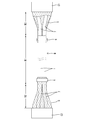
- the shield conductive path W in the first embodiment is provided at a front portion of the vehicle B and a device M1 such as a high voltage battery provided at the rear of the vehicle B, as shown in FIG. It is arranged along the floor of the vehicle B in order to connect with the device M2 such as the inverter or the fuse box which has been set via the connectors C1 and C2.
- a device M1 such as a high voltage battery provided at the rear of the vehicle B, as shown in FIG. It is arranged along the floor of the vehicle B in order to connect with the device M2 such as the inverter or the fuse box which has been set via the connectors C1 and C2.
- an intermediate portion in the front-rear direction of the vehicle B constitutes a rigid region R1 and both ends constitute a flexible region R2.
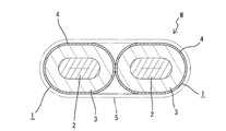
- the rigid region R1 is provided with two conductive members 1 each having a shape retention function, and is arranged in a contact state in which the under floor of the vehicle B is arranged in parallel in the vehicle width direction (see FIG. 3).
- the middle portion of the conductive member 1 is wired with a predetermined bending shape in the vehicle width direction and the height difference direction. The step of bending the conductive member 1 is performed after the conductive member 1 is assembled through the steps of inserting the conductor portion 2 and the like.
- the conductive members 1 of the first embodiment individually surround a plurality of (two in the first embodiment) conductor portions 2 with the shield portions 4 via the insulating portions 3 respectively. It is electromagnetically shielded.
- the conductor part 2 in the present Example 1 is comprised by the single core wire electric wire. That is, the conductor portion 2 in this embodiment is made of a long conductive metal pipe made of copper, copper alloy, aluminum or aluminum alloy. In the case of the first embodiment, the conductor portion 2 mainly functions as the shape holding member of the present invention.
- a cylindrical insulating portion 3 (insulating resin layer) is concentrically stacked on the entire outer peripheral surface of the conductor portion 2.
- the conductor portion 2 is crushed in the vehicle height direction together with the insulating portion 3 and has a shape (elliptical shape) extending flatly in the vehicle width direction over the entire length. As a result, the conductive member 1 is reduced in height in the vehicle height direction.
- the shield portion 4 is formed by winding a ribbon-like member made of a conductive metal foil spirally without gaps around the entire length and adhering it to the outer peripheral surface of the insulating portion 3.
- the winding step of the shield portion 4 may be performed after the bending step of the conductor portion 2 and the insulating portion 3 described above.
- a coating of a predetermined color for example, orange is applied to the entire surface of the shield portion 4 to alert the high voltage current and protect it from collision with foreign matter. You may make it plan.
- both conductive members 1 in the first embodiment are configured to be individually surrounded by the shield portion 4.
- the flexible region R2 is required to be able to be flexibly arranged because it is arranged in a relatively narrow space in the engine compartment or the passenger compartment. For this reason, in the present embodiment, the flexible region R2 adopts a configuration in which the two stranded wires 7 having flexibility are collectively surrounded by the braiding member 5.
- the insulation coating is peeled off at the end of the double stranded wire 7 to expose a core (not shown).
- both end portions of the conductor portion 2 project from the both ends of the insulating portion 3 and the shield portion 4 in the front-rear direction.
- the exposed core of the stranded wire 7 is connected to the upper surface or the lower surface of the crushed surface of the corresponding conductor 2 by welding or the like at both projecting ends of the conductor 2.
- a terminal fitting (not shown) is connected to the other end of the stranded wire 7 and the terminal fitting is accommodated in the connectors C1 and C2.
- the braid member 5 has a configuration in which a large number of conductive metal thin wires are tubularly knitted, and has excellent flexibility.
- the ends on the rigid region R1 side of the braided member 5 are collectively fitted to both the conductive members 1, are respectively clamped and fixed by the clamping members 6, and are electrically connected to the shield portion 4.
- the other end of the braided member 5 is electrically connected to a conductive metal shield member (not shown) attached to the corresponding connectors C1 and C2.
- the shield conductive path W in the first embodiment adopts a method in which shields for the respective conductive members 1 are separately surrounded. There is. That is, if the conductive members arranged in parallel in the vehicle width direction are collectively encircled by the shield portion having a circular cross section, empty spaces must be generated above and below the both conductive members in the shield portion. Conventionally, this has been a factor that prevents the reduction in height of the shield conductive path, but as in the first embodiment, if the form in which the shield portions 4 individually surround the conductor portions 2 and the insulating portions 3 is adopted.
- the shield portion 4 can surround the outer peripheral surface of the conductor portion 2 and the insulating portion 3 substantially in intimate contact. Therefore, unlike the prior art, since unnecessary empty spaces do not occur in the upper and lower portions in the shield portion 4, the height reduction of the shield conductive path W can be surely achieved.
- the conductor portion 2 is formed by crushing the metal pipe in the vehicle height direction, there is an effect that the height can be further improved.
- the conductive member 1 generates heat when it is energized
- the upper and lower spaces in the shield portion cause heat to be dissipated, which may lower the electrical characteristics of the conductor portion. I was concerned.
- the shield part 4 is enclosed in close contact with the insulating part 3, the heat generated in the conductor part 2 is smoothly dissipated to the outside by the heat radiation path formed by the conductor 2, the insulating part 3 and the shield part 4. Can be effective in maintaining the electrical characteristics of the conductor portion 2.
- the conductor portion 2 is constituted by a single cored wire obtained by processing a metal pipe, the conductor portion 2 can be mainly functioned as a shape holding member for holding a predetermined bending shape. ing. Therefore, it is not necessary to add a special member for shape retention, which also contributes to the reduction of the number of parts and the simplification of the configuration.
- FIG. 4 shows a conductive member 10 according to a second embodiment of the present invention.
- the conductor part 11 in the present Example 2 is comprised by the strand wire.
- the conductor portion 11 is composed of a core wire 11A in which a large number of thin wires are twisted in a spiral shape, and an insulating coating 11B surrounding the outer peripheral side thereof.
- the conductor portion 11 itself has flexibility and is in a so-called waistless state.
- the insulating portion 12 is made of a synthetic resin pipe having a circular cross section. In the second embodiment, the insulating portion 12 functions as the shape holding member of the present invention.
- the conductor portion 11 is loosely inserted from one end of the insulating portion 12 and surrounds the outer periphery of the conductor portion 11 substantially concentrically with a slight gap.
- the insulating portion 12 is formed through a bending process so as to have a predetermined bent shape after the conductor portion 11 is inserted.
- the insulating portion 12 is preferably bent in consideration of the amount of return after the bending process.
- the insulating portion 12 has a single-layer structure made of a synthetic resin material, and also has a multi-layer structure including a metal layer so that the shape retention function can be enhanced It is also conceivable to Both end portions of the conductor portion 11 project from the insulating portion 12 and the shield portion 13 described below in both the front and back directions of the vehicle, and are connected to the electric wire of the flexible region R2.
- the shield portion 13 is formed of a conductive metal layer laminated on the entire outer peripheral surface of the insulating portion 12. Therefore, the shield portion 13 is accommodated in a state in which the conductor portion 11 is surrounded substantially concentrically from the entire circumference.
- Both shield parts 13 in the rigid area R1 may be connected together with the braided member 5 in the flexible area R2, but without connecting both shield parts 13 from the rigid area R1 to the flexible area R2 It may be integrally extended as it is, and both may be connected to shield members (not shown) of the connectors C1 and C2.
- the shield portion 13 individually surrounds the conductor portion 11 and the insulating portion 12 and does not create a space in the height direction between them. , It is effective in height reduction and heat dissipation function.
- the shield portion 13 which is a metal member can protect the insulating portion 12 and the conductor portion 11. Further, by providing the shield portion 13, it is also expected that the spring back of the insulating portion 12 at the time of the bending process is alleviated, whereby the shape holding function of the insulating portion 12 can be enhanced.
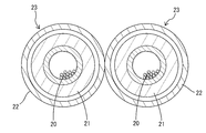
- FIG. 5 shows a third embodiment of the present invention.
- the conductor part 20 in the present Example 3 is also comprised by the strand wire electric wire similarly to Example 2.
- the insulation part 21 of the present Example 3 is comprised by the insulation coating of a strand wire.
- the shield portion 22 is formed of a conductive metal pipe.
- the shield portion 22 functions as the shape holding member of the present invention.
- the conductor portion 20 and the insulating portion 21 are loosely inserted from one end side of the shield portion 22. Therefore, the conductor portion 20 and the insulating portion 21 in each conductive member 23 are individually surrounded by the shield portion 22.
- a proper gap necessary for the insertion work to the shield part 22 is kept, but this gap is only a small degree compared with the gap which has been generated conventionally. .
- the shield part 22 is made into a predetermined
- Both ends of the conductor portion 20 project in the front-rear direction from the shield portion 22 in a state in which the insulating coating is peeled off, and are connected to the wires of the flexible region R2.
- Both shield portions 22 in the rigid region R1 and the braided members 5 in the flexible region R2 are connected by the fastening member 6 in the same manner as in the first embodiment.
- the shield portion 22 individually surrounds the conductor portion 20 and the insulating portion 21 and generates an unnecessary space in the height direction between them. Because it does not let you do, it becomes effective in heightening the height and heat dissipation function.
- the insulating portion 21 performs the shape retention function, there is a concern about springback in the bending step.
- the third embodiment there is no such concern, so that the advantage of easy shape retention is obtained. is there.
- the shield part 22 is formed with a predetermined thickness in order to maintain its shape, the protective function for the conductor part 20 and the like is also high.
- the conductor portion 2 is formed of metal pipe material, but it may be replaced with a pipe material and replaced with a long flat plate, or a bar material having a circular cross section may be crushed from the height direction. You may.
- the method of manufacturing the shield portion 4 by spirally winding and bonding the ribbon-like member is described, but instead, metal foil is laminated on the entire outer peripheral surface of the insulating portion 3 Alternatively, the outer peripheral surface may be surrounded by laminating a protective layer made of a resin material.
- the shield conductive path W is formed of two conductive members. However, the number of conductive members is not limited as long as it is two or more.
Landscapes
- Engineering & Computer Science (AREA)
- Mechanical Engineering (AREA)
- Insulated Conductors (AREA)
- Microelectronics & Electronic Packaging (AREA)
- Details Of Indoor Wiring (AREA)
- Shielding Devices Or Components To Electric Or Magnetic Fields (AREA)
Priority Applications (2)
| Application Number | Priority Date | Filing Date | Title |
|---|---|---|---|
| US16/637,798 US10770200B2 (en) | 2017-08-08 | 2018-07-18 | Shielded conductive path |
| CN201880048357.3A CN111052268B (zh) | 2017-08-08 | 2018-07-18 | 屏蔽导电路径 |
Applications Claiming Priority (2)
| Application Number | Priority Date | Filing Date | Title |
|---|---|---|---|
| JP2017153013A JP2019032990A (ja) | 2017-08-08 | 2017-08-08 | シールド導電路 |
| JP2017-153013 | 2017-08-08 |
Publications (1)
| Publication Number | Publication Date |
|---|---|
| WO2019031167A1 true WO2019031167A1 (ja) | 2019-02-14 |
Family
ID=65271263
Family Applications (1)
| Application Number | Title | Priority Date | Filing Date |
|---|---|---|---|
| PCT/JP2018/026807 Ceased WO2019031167A1 (ja) | 2017-08-08 | 2018-07-18 | シールド導電路 |
Country Status (4)
| Country | Link |
|---|---|
| US (1) | US10770200B2 (enExample) |
| JP (1) | JP2019032990A (enExample) |
| CN (1) | CN111052268B (enExample) |
| WO (1) | WO2019031167A1 (enExample) |
Families Citing this family (4)
| Publication number | Priority date | Publication date | Assignee | Title |
|---|---|---|---|---|
| JP7047649B2 (ja) * | 2018-07-30 | 2022-04-05 | 株式会社オートネットワーク技術研究所 | ワイヤハーネス |
| US20220108829A1 (en) * | 2019-02-15 | 2022-04-07 | Eaglerise Intelligent Device Corporation Ltd. | Wire for use in transformer winding and transformer |
| JP7392559B2 (ja) * | 2020-04-15 | 2023-12-06 | 株式会社オートネットワーク技術研究所 | ワイヤハーネス |
| CN112562892A (zh) * | 2020-12-18 | 2021-03-26 | 长春捷翼汽车零部件有限公司 | 扁带式导电线体及扁带式线束 |
Citations (5)
| Publication number | Priority date | Publication date | Assignee | Title |
|---|---|---|---|---|
| WO2013137230A1 (ja) * | 2012-03-14 | 2013-09-19 | 矢崎総業株式会社 | 同軸電線、及び同軸電線の製造方法 |
| JP2014123478A (ja) * | 2012-12-21 | 2014-07-03 | Auto Network Gijutsu Kenkyusho:Kk | 絶縁被覆電線及びその製造方法 |
| JP2015088251A (ja) * | 2013-10-28 | 2015-05-07 | 矢崎総業株式会社 | 回路導体、接続構造、及び回路導体の製造方法 |
| JP2016136460A (ja) * | 2015-01-23 | 2016-07-28 | 矢崎総業株式会社 | ワイヤハーネス |
| JP2017099155A (ja) * | 2015-11-25 | 2017-06-01 | 住友電装株式会社 | 電線外装材およびワイヤハーネス |
Family Cites Families (6)
| Publication number | Priority date | Publication date | Assignee | Title |
|---|---|---|---|---|
| US1853677A (en) * | 1928-10-20 | 1932-04-12 | Siemensschuckertwerke Ag | Telephone cable |
| JP2006311699A (ja) | 2005-04-28 | 2006-11-09 | Auto Network Gijutsu Kenkyusho:Kk | シールド導電路 |
| US20080173464A1 (en) * | 2007-01-18 | 2008-07-24 | Rajendran Nair | Shielded flat pair cable with integrated resonant filter compensation |
| JP6281448B2 (ja) * | 2014-09-03 | 2018-02-21 | 住友電装株式会社 | 導電路 |
| US9875824B2 (en) * | 2014-12-24 | 2018-01-23 | Yazaki Corporation | Waterproofing structure, waterproofing method and wire harness |
| JP6657613B2 (ja) * | 2015-06-18 | 2020-03-04 | ダイキン工業株式会社 | 空気調和装置 |
-
2017
- 2017-08-08 JP JP2017153013A patent/JP2019032990A/ja active Pending
-
2018
- 2018-07-18 CN CN201880048357.3A patent/CN111052268B/zh not_active Expired - Fee Related
- 2018-07-18 WO PCT/JP2018/026807 patent/WO2019031167A1/ja not_active Ceased
- 2018-07-18 US US16/637,798 patent/US10770200B2/en active Active
Patent Citations (5)
| Publication number | Priority date | Publication date | Assignee | Title |
|---|---|---|---|---|
| WO2013137230A1 (ja) * | 2012-03-14 | 2013-09-19 | 矢崎総業株式会社 | 同軸電線、及び同軸電線の製造方法 |
| JP2014123478A (ja) * | 2012-12-21 | 2014-07-03 | Auto Network Gijutsu Kenkyusho:Kk | 絶縁被覆電線及びその製造方法 |
| JP2015088251A (ja) * | 2013-10-28 | 2015-05-07 | 矢崎総業株式会社 | 回路導体、接続構造、及び回路導体の製造方法 |
| JP2016136460A (ja) * | 2015-01-23 | 2016-07-28 | 矢崎総業株式会社 | ワイヤハーネス |
| JP2017099155A (ja) * | 2015-11-25 | 2017-06-01 | 住友電装株式会社 | 電線外装材およびワイヤハーネス |
Also Published As
| Publication number | Publication date |
|---|---|
| CN111052268A (zh) | 2020-04-21 |
| CN111052268B (zh) | 2022-03-15 |
| US10770200B2 (en) | 2020-09-08 |
| JP2019032990A (ja) | 2019-02-28 |
| US20200258657A1 (en) | 2020-08-13 |
Similar Documents
| Publication | Publication Date | Title |
|---|---|---|
| JP5986812B2 (ja) | ワイヤハーネス | |
| US10602647B2 (en) | Electromagnetic shield component and wire harness | |
| JP6002985B2 (ja) | ワイヤハーネス用中間部材及びワイヤハーネス | |
| JP6979957B2 (ja) | 電磁シールド構造およびワイヤハーネス | |
| JP5830339B2 (ja) | 編組及びワイヤハーネス | |
| JP7047649B2 (ja) | ワイヤハーネス | |
| WO2011078234A1 (ja) | ワイヤーハーネス | |
| WO2019031167A1 (ja) | シールド導電路 | |
| WO2011158868A1 (ja) | 一体型シールドプロテクタ及びワイヤハーネス | |
| CN104395970A (zh) | 多层同轴电缆 | |
| CN101755310A (zh) | 屏蔽导体 | |
| JP2016054030A (ja) | ワイヤハーネスおよびシールド導電路 | |
| US10596983B2 (en) | Wire harness | |
| JP2016054031A (ja) | 導電路 | |
| JP2016195078A (ja) | 配線部材 | |
| CN103703521B (zh) | 高压导电路径和线束 | |
| CN112771630B (zh) | 线束 | |
| JP6819642B2 (ja) | ワイヤハーネス | |
| WO2020066587A1 (ja) | ワイヤハーネス | |
| JP5781289B2 (ja) | ワイヤハーネス配索構造 | |
| JP6700613B2 (ja) | 導電線 | |
| JP7160791B2 (ja) | 電線 | |
| JP2015015856A (ja) | ワイヤハーネス | |
| JP2006269666A (ja) | シールド構造体 | |
| JP4820573B2 (ja) | シールド導電路 |
Legal Events
| Date | Code | Title | Description |
|---|---|---|---|
| 121 | Ep: the epo has been informed by wipo that ep was designated in this application |
Ref document number: 18844707 Country of ref document: EP Kind code of ref document: A1 |
|
| NENP | Non-entry into the national phase |
Ref country code: DE |
|
| 122 | Ep: pct application non-entry in european phase |
Ref document number: 18844707 Country of ref document: EP Kind code of ref document: A1 |