WO2019026725A1 - 回転電機 - Google Patents
回転電機 Download PDFInfo
- Publication number
- WO2019026725A1 WO2019026725A1 PCT/JP2018/027897 JP2018027897W WO2019026725A1 WO 2019026725 A1 WO2019026725 A1 WO 2019026725A1 JP 2018027897 W JP2018027897 W JP 2018027897W WO 2019026725 A1 WO2019026725 A1 WO 2019026725A1
- Authority
- WO
- WIPO (PCT)
- Prior art keywords
- winding
- rotor
- stator
- windings
- rotation
- Prior art date
Links
Images


Classifications
-
- H—ELECTRICITY
- H02—GENERATION; CONVERSION OR DISTRIBUTION OF ELECTRIC POWER
- H02K—DYNAMO-ELECTRIC MACHINES
- H02K1/00—Details of the magnetic circuit
- H02K1/06—Details of the magnetic circuit characterised by the shape, form or construction
- H02K1/12—Stationary parts of the magnetic circuit
-
- H—ELECTRICITY
- H02—GENERATION; CONVERSION OR DISTRIBUTION OF ELECTRIC POWER
- H02K—DYNAMO-ELECTRIC MACHINES
- H02K21/00—Synchronous motors having permanent magnets; Synchronous generators having permanent magnets
- H02K21/12—Synchronous motors having permanent magnets; Synchronous generators having permanent magnets with stationary armatures and rotating magnets
- H02K21/14—Synchronous motors having permanent magnets; Synchronous generators having permanent magnets with stationary armatures and rotating magnets with magnets rotating within the armatures
-
- H—ELECTRICITY
- H02—GENERATION; CONVERSION OR DISTRIBUTION OF ELECTRIC POWER
- H02K—DYNAMO-ELECTRIC MACHINES
- H02K1/00—Details of the magnetic circuit
- H02K1/06—Details of the magnetic circuit characterised by the shape, form or construction
- H02K1/12—Stationary parts of the magnetic circuit
- H02K1/18—Means for mounting or fastening magnetic stationary parts on to, or to, the stator structures
- H02K1/182—Means for mounting or fastening magnetic stationary parts on to, or to, the stator structures to stators axially facing the rotor, i.e. with axial or conical air gap
-
- H—ELECTRICITY
- H02—GENERATION; CONVERSION OR DISTRIBUTION OF ELECTRIC POWER
- H02K—DYNAMO-ELECTRIC MACHINES
- H02K1/00—Details of the magnetic circuit
- H02K1/06—Details of the magnetic circuit characterised by the shape, form or construction
- H02K1/22—Rotating parts of the magnetic circuit
- H02K1/27—Rotor cores with permanent magnets
- H02K1/2793—Rotors axially facing stators
-
- H—ELECTRICITY
- H02—GENERATION; CONVERSION OR DISTRIBUTION OF ELECTRIC POWER
- H02K—DYNAMO-ELECTRIC MACHINES
- H02K11/00—Structural association of dynamo-electric machines with electric components or with devices for shielding, monitoring or protection
- H02K11/01—Structural association of dynamo-electric machines with electric components or with devices for shielding, monitoring or protection for shielding from electromagnetic fields, i.e. structural association with shields
-
- H—ELECTRICITY
- H02—GENERATION; CONVERSION OR DISTRIBUTION OF ELECTRIC POWER
- H02K—DYNAMO-ELECTRIC MACHINES
- H02K11/00—Structural association of dynamo-electric machines with electric components or with devices for shielding, monitoring or protection
- H02K11/20—Structural association of dynamo-electric machines with electric components or with devices for shielding, monitoring or protection for measuring, monitoring, testing, protecting or switching
- H02K11/21—Devices for sensing speed or position, or actuated thereby
- H02K11/22—Optical devices
-
- H—ELECTRICITY
- H02—GENERATION; CONVERSION OR DISTRIBUTION OF ELECTRIC POWER
- H02K—DYNAMO-ELECTRIC MACHINES
- H02K11/00—Structural association of dynamo-electric machines with electric components or with devices for shielding, monitoring or protection
- H02K11/30—Structural association with control circuits or drive circuits
-
- H—ELECTRICITY
- H02—GENERATION; CONVERSION OR DISTRIBUTION OF ELECTRIC POWER
- H02K—DYNAMO-ELECTRIC MACHINES
- H02K16/00—Machines with more than one rotor or stator
-
- H—ELECTRICITY
- H02—GENERATION; CONVERSION OR DISTRIBUTION OF ELECTRIC POWER
- H02K—DYNAMO-ELECTRIC MACHINES
- H02K21/00—Synchronous motors having permanent magnets; Synchronous generators having permanent magnets
- H02K21/12—Synchronous motors having permanent magnets; Synchronous generators having permanent magnets with stationary armatures and rotating magnets
- H02K21/24—Synchronous motors having permanent magnets; Synchronous generators having permanent magnets with stationary armatures and rotating magnets with magnets axially facing the armatures, e.g. hub-type cycle dynamos
-
- H—ELECTRICITY
- H02—GENERATION; CONVERSION OR DISTRIBUTION OF ELECTRIC POWER
- H02K—DYNAMO-ELECTRIC MACHINES
- H02K3/00—Details of windings
- H02K3/04—Windings characterised by the conductor shape, form or construction, e.g. with bar conductors
- H02K3/12—Windings characterised by the conductor shape, form or construction, e.g. with bar conductors arranged in slots
- H02K3/16—Windings characterised by the conductor shape, form or construction, e.g. with bar conductors arranged in slots for auxiliary purposes, e.g. damping or commutating
-
- H—ELECTRICITY
- H02—GENERATION; CONVERSION OR DISTRIBUTION OF ELECTRIC POWER
- H02K—DYNAMO-ELECTRIC MACHINES
- H02K3/00—Details of windings
- H02K3/04—Windings characterised by the conductor shape, form or construction, e.g. with bar conductors
- H02K3/28—Layout of windings or of connections between windings
-
- H—ELECTRICITY
- H02—GENERATION; CONVERSION OR DISTRIBUTION OF ELECTRIC POWER
- H02K—DYNAMO-ELECTRIC MACHINES
- H02K3/00—Details of windings
- H02K3/46—Fastening of windings on the stator or rotor structure
-
- H—ELECTRICITY
- H02—GENERATION; CONVERSION OR DISTRIBUTION OF ELECTRIC POWER
- H02P—CONTROL OR REGULATION OF ELECTRIC MOTORS, ELECTRIC GENERATORS OR DYNAMO-ELECTRIC CONVERTERS; CONTROLLING TRANSFORMERS, REACTORS OR CHOKE COILS
- H02P6/00—Arrangements for controlling synchronous motors or other dynamo-electric motors using electronic commutation dependent on the rotor position; Electronic commutators therefor
- H02P6/28—Arrangements for controlling current
Definitions
- the present invention relates to a rotating electrical machine having a rotor with permanent magnets and a stator with windings.
- a rotating electrical machine such as a motor or a generator includes a rotor and a stator.
- the stator excites the rotor.
- the winding is wound around the iron core such that the axis of the winding is directed to the rotor.
- a winding is wound around a part of a C-shaped iron core, and a rotor is disposed between both ends of the facing iron core.
- Patent Document 4 a stator formed by winding a hollow cylindrical core and a permanent magnet in which m N poles and S poles are alternately arranged in the circumferential direction are formed, and minute air is formed in the core of the stator.
- a toroidal core type actuator is described having a rotor rotatably disposed via a gap.
- the stator when the magnetic poles of the rotor are directed to the end of the stator, the stator is such that the magnetic path from the end of the stator to the inside of the stator is the main magnetic flux direction from the rotor It is formed in the direction that intersects the Therefore, when the rotor passes toward the end of the stator, the magnetic path from the end of the stator to the inside of the stator crosses the direction of the main magnetic flux from the rotor. Since the change in magnetic flux is smaller than that of the conventional motor in which the direction of the wire is directed in the radial direction, the back electromotive force can be made smaller than that of the conventional motor described in Patent Documents 1 to 3.
- a recess is formed on the outer circumferential surface of the housing, the rotor magnet is housed in the recess and the lid is provided, and even if the rotor magnet does not pop out, a minute air gap is generated between the rotor magnet and the coil. The reason is that the thinner the lid is, the easier it is to break the lid.
- the reliability can not be maintained in long-time operation when the rotor portion rotates at high speed.
- the present invention can achieve high rotation without applying high voltage by suppressing generation of back electromotive force, and can maintain the reliability of the rotor even if high rotation is continued for a long time
- An object of the present invention is to provide a rotating electrical machine.
- a plurality of permanent magnets are disposed on the housing along the rotation circumference, and the magnetic poles of the permanent magnets are disposed along the rotation circumference and the rotor oriented in the direction along the rotation axis.
- a stator having a plurality of windings, wherein the winding has a magnetic path from the end of the winding to the inside of the winding when the magnetic pole of the permanent magnet is directed to the winding.
- a plurality of stators are formed along a rotational axis of the rotor, and are formed in a direction intersecting with a main magnetic flux direction from permanent magnets, and each of the stators is formed of coils forming the stator. It is characterized in that the gap is disposed at a position shifted in the circumferential direction of rotation.
- the rotating electrical machine of the present invention when the rotor passes toward the end of the winding of the stator, the magnetic path from the end of the winding to the inside of the winding is the main magnetic flux direction from the rotor Since the change in the magnetic flux is smaller than in the conventional electric motor in which the direction of the winding is directed in the radial direction, the back electromotive force can be made smaller than that of the conventional electric motor. Also, the permanent magnets of the rotor are oriented in the direction along the rotation axis, and the stator is arranged with a winding along the rotation circumference in the direction in which the magnetic poles of the permanent magnets are directed.
- a plurality of stators are provided along the rotational axis of the rotor, and each of the stators is disposed at a position where the gaps between the windings forming the stator are offset in the circumferential direction of rotation. Therefore, the permanent magnet housed in the housing is different from the direction in which the centrifugal force acts and the direction in which the magnetic pole faces the winding. The permanent magnet can be made less likely to pop out of the housing even if it is rotated. In addition, even if the rotor tries to decelerate or stop at the gap between the ends of the stator, rotational drive can be applied by another stator.
- a plurality of permanent magnets are arranged on the housing along the rotation circumference, and the rotor has the magnetic poles of the permanent magnets oriented in the direction along the rotation axis,
- a stator having a plurality of windings disposed, the windings having a magnetic path from the end of the winding into the winding when the magnetic pole of the permanent magnet is directed to the winding
- An auxiliary winding is formed between the end portions of the plurality of windings formed in a direction intersecting the main magnetic flux direction from the permanent magnet.
- the rotating electrical machine of the present invention when the rotor passes toward the end of the winding of the stator, the magnetic path from the end of the winding to the inside of the winding is the main magnetic flux direction from the rotor Since the change in the magnetic flux is smaller than in the conventional electric motor in which the direction of the winding is directed in the radial direction, the back electromotive force can be made smaller than that of the conventional electric motor.
- the permanent magnets of the rotor are oriented in the direction along the rotation axis, and the stator is arranged with a winding along the rotation circumference in the direction in which the magnetic poles of the permanent magnets are directed. Then, auxiliary windings are provided between the ends of the plurality of windings.
- the permanent magnet housed in the housing is different from the direction in which the centrifugal force acts and the direction in which the magnetic pole faces the winding.
- the permanent magnet can be made less likely to pop out of the housing even if it is rotated.
- the magnetic force generated between the ends of the plurality of windings can be complemented by the auxiliary winding, the rotational driving force of the rotor can be enhanced by the auxiliary winding. .
- the rotor may be disposed on both sides of the stator.
- the stator may be formed by the arc-shaped winding along the rotation circumference of the rotor.
- the windings of the stator are arc-shaped along the circumferential direction around the rotation axis of the rotor, so that the magnetic path from the end of the stator to the inside of the stator and the main magnetic flux direction from the rotor It can be in the direction intersecting with the
- the stator may be formed by the winding in which an axis along a tangent of a rotation circumference of the rotor is linear. It is easy to manufacture by making the axis of the winding linear.
- the stator may be formed of a plurality of parallel-connected windings surrounding the rotational center of the rotor. By forming a plurality of windings connected in parallel, the resistance value of the windings can be reduced.
- the permanent magnet may be disposed closer to the axis of the winding. it can.
- a rotational speed adjustment unit may be connected to adjust the current from the power generation winding. Since the power generation winding is coaxial with the auxiliary winding, the magnetic field generated in the power generation winding acts to assist the auxiliary winding. Therefore, the number of rotations of the permanent magnet can be adjusted according to the current flowing through the rotation speed adjustment unit.
- the rotation speed adjustment unit may include a rectification unit connected to the power generation winding, and a consumption unit that consumes the current from the rectification unit.
- the consumption part can adjust the number of rotations of the permanent magnet in accordance with the current that consumes the direct current rectified by the rectification part, and the consumption part can effectively utilize the current.
- the rotating electrical machine of the present invention since the change in magnetic flux is smaller than that of the conventional electric motor in which the winding direction is directed in the radial direction, the back electromotive force can be smaller than that of the conventional electric motor. Even if it does not apply, it can be made high rotation. Further, even if the rotor is rotated at high speed, it is possible to make it difficult for the permanent magnet to fly out of the housing. Therefore, by suppressing the generation of the back electromotive force, the rotating electric machine of the present invention can achieve high rotation without applying high voltage, and maintain the reliability of the rotor even if high rotation is continued for a long time can do.
- FIG. 14 is a diagram of an upper stage stator of the motor shown in FIG. 13 and an upper stage permanent magnet facing the stator.
- FIG. 14 is a perspective view of a state where the rotor has rotated 45 degrees from the state of the motor shown in FIG. 13;
- FIG. 16 is a diagram of an upper stage stator of the electric motor shown in FIG.
- the stator of the motor shown in FIG. 5 is a winding having an elliptical cross section, and is a view of the motor in which a rotor is also provided on the opposite side of the stator.
- Embodiment 1 A rotating electrical machine according to a first embodiment of the present invention will be described based on the drawings, using a motor as an example.
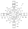
- 1 (A) and 1 (B) are schematic diagrams for explaining the motor according to the first embodiment, which supports the stator and the output shaft, and supports the sensor unit and the like. The housing is not shown.
- the motor 10 shown in FIGS. 1A and 1B includes a rotor 20 formed coaxially with the output shaft O1, and a stator 30 for exciting a magnetic flux that rotationally drives the rotor 20. .
- a plurality of permanent magnets 22 are disposed along the rotation circumference R1 in the housing 21, and one of the N pole and the S pole of the permanent magnet 22 is directed in the direction along the rotation axis L1.
- the housing 21 is formed in a disk shape, and stores the permanent magnets 22 at equal intervals along the rotation circumference R1.
- the permanent magnet 22 is formed in a rectangular parallelepiped, and is disposed in the housing 21 so that the magnetic poles of either one of the N pole and the S pole are alternately directed to the stator 30.
- four permanent magnets 22 are provided in the housing 21 every 90 degrees.
- the permanent magnet 22 can use a neodymium magnet whose magnetic force is stronger than other magnets.
- the stator 30 is formed of a plurality of windings C1 (first to fourth windings 31 to 34), and the winding C1 is disposed along the rotation circumference R1 in the direction in which the magnetic poles of the permanent magnet 22 face. There is.
- the stator 30 when the rotor 20 faces the end of the winding C1 (ends 31T1, 31T2, 32T1, 32T2, 33T1, 33T2, 34T1, 34T2), the inside of the winding from the end of the winding C1
- a magnetic path R (see FIG. 4) is formed in a direction intersecting the main magnetic flux direction F1 from the rotor 20.
- the winding C1 is formed in an arc shape along the rotation circumference R1 around the rotation axis L1 of the rotor 20.
- the end 31T1 of the first winding 31 and the end 34T1 of the fourth winding 34 are connected to the exciting circuit portion 42 of the control circuit 40, and the facing end 31T2 , 32T2's, end portions 32T1, 33T1's and end portions 33T2, 34T2's are connected in series, so that they are connected in series, but they may be connected in parallel.
- the windings C1 of the first winding 31 to the fourth winding 34 are energized, one end 31T1, 34T1 facing each other, the ends 32T1, 33T1 have the same pole, and the other ends 31T2, 32T2 meet each other,
- the wiring is wound such that the ends 33T2 and 34T2 generate the same polarity.
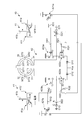
- the control circuit 40 includes a sensor unit 41 and an excitation circuit unit 42.
- the sensor unit 41 detects timing when one end 31T1, 34T1 and one end 32T1, 33T1 are N pole and the other end 31T2, 32T2 and one end 33T2, 34T2 are S poles. On the other hand, it detects timings in which one end 31T1, 34T1 and one end 32T1, 33T1 are S poles and the other end 31T2, 32T2 and one end 33T2, 34T2 are N poles.
- the first sensor unit 411 and the second sensor unit 412 are provided.
- the first sensor unit 411 and the second sensor unit 412 rotate together with the rotor 20 and the transmission type photo interrupter 41 a by the light emitting diode and the photodiode fixed by the support member (not shown), and the transmission type photo interrupter 41 a And a disk-shaped shielding plate 41b passing between the light emitting diode and the photodiode.
- the shield plate 41b is provided. Are commonly provided to the first sensor unit 411 and the second sensor unit 412.
- the shielding board 41b is used in common by the 1st sensor part 411 and the 2nd sensor part 412, in FIG. 2, the shielding board 41b is shown separately corresponding to the photo-interrupter 41a. There is.
- An arc-shaped cutout 41c (see FIG. 1A) for defining the energization timing and the energization time is formed along a circumferential direction on a part of the peripheral edge of the shielding plate 41b.
- the arc-shaped notches 41c are formed in a range of 90 degrees in accordance with the position of the N pole of the permanent magnet 22, and are formed at two positions on the periphery of the shielding plate 41b.
- the photo interrupter 41a is a position where one end 31T1, 34T1 of the first winding 31 and the fourth winding 34 face each other at a position of 0 degrees, and one end where the second winding 32 and the third winding 33 face each other. When the positions of the portions 32T1 and 32T1 are 180 degrees, they are formed at 0 degrees and 90 degrees.
- the excitation circuit unit 42 shown in FIG. 2 controls the energization of the first winding 31 to the fourth winding 34.
- the exciting circuit unit 42 includes the first sensor unit 411 and the second sensor unit 412 as one set, and the transistors from the first FETs 421a and 421b to the third FETs 423a and 423b control the first winding 31 to the fourth winding 34. Control the direction of energization.
- the first FET 421a and the third FET 423a are n-type FETs.
- the second FETs 422a and 422b are p-type FETs.
- the gate terminals G of the first FETs 421a and 421b are connected to the photo interrupter 41a via the resistors R11 and R12.
- the source terminals S of the first FETs 421a and 421b are grounded.
- the source terminals S of the second FETs 422a and 422b are connected to the power supply via the diodes D11 and D12, and are grounded via the capacitors C11 and C12.
- the gate terminals G of the second FETs 422a and 422b are connected to the drain terminals D of the first FETs 421a and 421b via the resistors R21 and R22, and to the source terminals S of the second FETs 422a and 422b via the resistors R31 and R32. It is connected.
- the drain terminals D of the second FETs 422a and 422b are connected to the anode terminals A of the diodes D21 and D22 and to the drain terminals D of the third FETs 423a and 423b.
- the gate terminals G of the third FETs 423a and 423b are connected to the photo interrupter 41a via the resistors R41 and R42.
- the source terminals S of the third FETs 423a and 423b are grounded.
- the wire from one end 34T1 of the fourth winding 34 is connected to the drain terminal D of the second FET 422a and to the drain terminal D of the third FET 423a.
- the wiring from one end 31T1 of the first winding 31 is connected to the drain terminal D of the second FET 422b and to the drain terminal D of the third FET 423b.
- the gate terminal G of the first FET 421a and the gate terminal G of the third FET 423a are connected to the photo interrupter 41a via the resistors R11 and R41. Is a first voltage at which the first FET 421a and the third FET 423a are turned on.
- the gate terminal G of the first FET 421b connected to the photo interrupter 41a of the second sensor unit 412 via the resistors R12 and R42 and the gate terminal G of the third FET 423b are the first FET 421b and The third FET 423 b is turned off, which is a second voltage (0 V) lower than the first voltage.
- the gate terminal G of the second FET 422a connected to the drain terminal D of the first FET 421b via the resistor R21 is turned off by the resistor R31 connected to the power supply Vss. It becomes a voltage.
- the resistor R22 is connected to the drain terminal D of the first FET 421a, so the gate terminal G of the second FET 422b is at the second voltage at which the second FET 422b is in the on state.
- the current from the power supply Vss flows into the source terminal S of the second FET 422b via the diode D12, and the second FET 422b
- the current flows from the drain terminal D of the first winding 31 to one end 31T1 of the first winding 31.
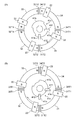
- the end 31T of the first winding 31 and the end 34T1 of the fourth winding 34 and the end 32T1 of the second winding 32 and the third winding A magnetic field of the same pole (N pole) repulsive to the N pole of the permanent magnet 22 is generated at the end 33T1 of 33, and the other end 31T2, the end 32T2, the end 33T2, the end 34T2 A magnetic field of the same polarity (S pole) repulsive to the S pole of the permanent magnet 22 is generated.
- the magnetic field generated by the first winding 31 to the fourth winding 34 causes the poles of the permanent magnet 22 to repel each other, and the rotor 20 rotates.
- the arc-shaped notch 41c of the shielding plate 41b is positioned in the photo interrupter 41a of the second sensor unit 412 in the sensor unit 41.
- the light from the photo interrupter 41 a of the second sensor unit 412 is transmitted through the arc-shaped notch 41 c of the shielding plate 41 b, whereby the phototransistor of the photo interrupter 41 a of the second sensor unit 412 is energized.
- the gate terminal G of the first FET 421 b and the gate terminal G of the third FET 423 b are connected to the photo interrupter 41 a via the resistors R12 and R42. Is a first voltage at which the first FET 421 b and the third FET 423 b are turned on.
- the arc-shaped cutout 41c is positioned in the photo interrupter 41a of the second sensor unit 412, the arc-shaped cutout 41c is not positioned in the photo interrupter 41a of the first sensor unit 411.
- the interrupter 41a is de-energized. Accordingly, the gate terminal G of the first FET 421a connected to the photo interrupter 41a of the first sensor unit 411 via the resistors R11 and R41 and the gate terminal G of the third FET 423a turn off the first FET 421a and the third FET 423a. , The second voltage.
- the gate terminal G of the second FET 422b connected to the drain terminal D of the first FET 421a via the resistor R22 is turned off by the resistor R32 connected to the power supply Vss. It becomes a voltage.
- the resistor R21 is connected to the drain terminal D of the first FET 421b, and therefore the gate terminal G of the second FET 422a becomes the second voltage at which the second FET 422a is in the on state.
- the current from the power supply Vss flows into the source terminal S of the second FET 422a through the diode D11, and the second FET 422a Flows from the drain terminal D of the second winding 34 to one end 34T1 of the fourth winding 34.
- a current flows from the fourth winding 34 to the third winding 33, the second winding 32 and the first winding 31 sequentially, and one end 31T1 of the first winding 31 to the drain terminal of the third FET 423b It flows to D and flows from the drain terminal D to the source terminal S of the third FET 423b.
- the end 31T of the first winding 31 and the end 34T1 of the fourth winding 34 and the end 32T1 of the second winding 32 and the third winding A magnetic field of the same pole (S pole) repulsive to the S pole of the permanent magnet 22 is generated at the end 33T1 of 33, and the other end 31T2, the end 32T2, the end 33T2, the end 34T2 A magnetic field of the same pole (N pole) repulsive to the N pole of the permanent magnet 22 is generated.
- the magnetic field generated by the first winding 31 to the fourth winding 34 causes the poles of the permanent magnet 22 to repel each other, and the rotor 20 rotates.
- the rotor 20 when the rotor 20 rotates, the other arc-shaped notch 41c formed in the shielding plate 41b is positioned at the photo interrupter 41a of the first sensor unit 411, so that the stator 30 shown in FIG. The magnetic field of the magnetic pole shown in FIG.
- the rotor 20 can keep rotating by alternately generating the magnetic pole shown in FIG. 3A and the magnetic pole shown in FIG. 3B in the stator 30.
- the stator 30 has a first winding 31 to a fourth winding 34 formed in an arc shape along the circumferential direction around the rotation axis L1 of the rotor 20. Therefore, as shown in FIG. 4, the magnetic path in the stator 30 is along the arc of the winding (the first winding 31 to the fourth winding 34).
- the respective magnetic poles of the permanent magnet 22 of the rotor 20 are directed to the ends of the first winding 31 to the fourth winding 34 (the end 31T1 of the first winding 31 and the 34T1 of the fourth winding 34 in FIG. 4)
- the magnetic path from the end of the stator 30 into the stator 30 is in the direction intersecting the main magnetic flux direction F1 from the rotor 20.
- the permanent magnets 22 of the rotor 20 are directed in the direction along the rotation axis L1, and the stator 30 is along the rotation circumference R1 in the direction in which the magnetic poles of the permanent magnets 22 are directed.
- a winding C1 is disposed. Therefore, the permanent magnet 22 housed in the housing 21 is different in the direction in which the centrifugal force acts (radial direction of the rotation circumference R1) and the direction in which the magnetic pole faces the winding C1.
- the permanent magnet 22 can be made difficult to pop out of the housing 21 even when the rotor 20 is rotated at high speed by disposing the housing 20 in proximity to the winding C1. Therefore, long-time operation can be made possible while maintaining the high speed rotation of the rotor 20.
- the motor 10 according to the first embodiment can achieve high rotation without applying a high voltage by suppressing the generation of the back electromotive force, and the rotor 20 can continue high rotation for a long time. Can maintain its credibility.
- the first winding 31 to the fourth winding 34 are formed in an arc shape along the rotation circumference R1 and formed into a circular shape as the stator 30.
- the curvature is larger or smaller than the rotation circumference. It may be done.
- the center of the winding in the longitudinal direction may not be orthogonal to the direction in which the magnetic poles of the permanent magnet are directed, and may be inclined.
- FIGS. 1A and 1B the housing for supporting the stator, the output shaft, the sensor unit, etc. is not shown in FIGS. 5A and 5B. .
- FIG. 5 (A) and the same figure (B) the thing of the same structure as FIG. 1 (A) and the same figure (B) attaches
- the winding C2 of the stator 30a is disposed along the rotation circumference R1 in the direction in which the magnetic pole of the permanent magnet 22 faces. Further, in the winding C2, an axis L2 along a tangent of the rotation circumference R1 of the rotor 20 is formed in a linear shape.
- the axis L2 of the winding C2 of the stator 30a is formed in a straight line, when the permanent magnet 22 faces the end of the winding C2, the end of the winding C2 starts from the end of the winding C2
- the winding C2 of the stator 30a is formed in a direction crossing the main magnetic flux direction from the permanent magnet 22 and the magnetic path to the magnetic flux path along the rotation circumference R1 in the direction in which the magnetic poles of the permanent magnet 22 face.
- a winding C2 is disposed. Therefore, the same operation and effect as those of the first embodiment can be obtained.
- the axis L2 of the winding C2 is formed in a straight line, when the wire is wound around the core, it can be evenly wound as compared with the arc-shaped winding C1 (see FIG. 1). Therefore, the winding C2 in which the axis L2 is straight can improve the workability.
- the magnetic poles of the permanent magnets of the rotor are directed outward in the radial direction of rotation and surrounded by the winding C2 of the stator 30a.
- the distance between the magnetic pole of the permanent magnet and the winding C2 approaches at the body of the winding C1, separates at the end, and is not constant.
- the distance between the magnetic pole of the permanent magnet 22 and the winding C2 is made constant. can do.
- FIG. 6 A rotating electrical machine according to a third embodiment of the present invention will be described based on the drawings, using a motor as an example.
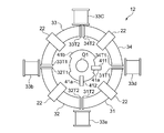
- the motor 12 according to the third embodiment shown in FIG. 6 is provided with auxiliary windings 33a to 33d in the motor 10 according to the first embodiment shown in FIGS. 1 (A) and 1 (B). It is.
- FIG. 6 the thing of the same structure as FIG. 1 (A) and the figure (B) attaches
- the auxiliary windings 33a to 33d are magnetic force enhancing windings formed in a straight tubular shape.
- the windings 33a to 33d are the facing ends of the first winding 31 to the fourth winding 34 (ends 31T1 and 34T1, ends 31T2 and 32T2, ends 32T1 and 33T1,
- the axial lines of the windings 33a to 33d are arranged outward in the radial direction of the circumference of the rotation, outside the end 33T2 and the end 34T2).
- the winding 33b has the same polarity as the end 31T2 and the end 32T2 so that the winding 33a has the same polarity as the end 31T1 and the end 34T1, and the winding 33c has the end 32T1.
- the winding 33d is further controlled by the control circuit 40 so as to have the same polarity as the end 33T2 and the end 34T21 so as to have the same polarity as the end 32T1.
- the auxiliary windings 33a to 33d face the axis and have the same poles as the magnetic poles generated by the ends of the windings.
- the magnetic forces at the respective end portions of the first winding 31 to the fourth winding 34 can be complemented by the windings 33a to 33d. Therefore, the rotational driving force of the rotor 20 can be increased by the windings 33a to 33d.
- FIG. 7 (Modification of Embodiment 3) A modification of the motor according to the third embodiment will be described based on the drawings.
- the motor 12a according to the third embodiment shown in FIG. 7 rotates the axis L3 of the auxiliary windings 33a to 33d along the rotation axis L1 with respect to the motor 12 according to the third embodiment shown in FIG.
- the coil C2 is directed to the child 20 side, and the winding C2 of the stator 30a is formed on the linear axis L2.
- FIG. 7 the same components as in FIG. 5 (A), FIG. 5 (B) and FIG. 6 are assigned the same reference numerals and descriptions thereof will be omitted.
- the magnetic flux from the windings 33a to 33d is directed to the rotor 20. Therefore, the magnetic forces of the respective end portions of the first winding 31 to the fourth winding 34 can be reinforced more strongly by the windings 33a to 33d.
- Embodiment 4 A rotating electrical machine according to a fourth embodiment of the present invention will be described based on the drawings, using a motor as an example.
- An electric motor 13 according to the fourth embodiment shown in FIG. 8 is the electric motor 12 according to the third embodiment shown in FIG. 6 provided with power generation windings 35a to 35d.
- the thing of the same structure as FIG. 6 attaches
- the motor 13 is provided with power generation windings 35a to 35d coaxially with the auxiliary windings 33a to 33d.
- a rotational speed adjustment unit 50 is connected to the power generation windings 35a to 35d.
- the rotational speed adjustment unit 50 includes a rectification unit 51 and a consumption unit 52.
- the rectifying unit 51 can be configured by a diode bridge.
- the consumer 52 may be a variable resistor, but may connect a load that effectively uses electrical energy instead of the variable resistor. For example, a battery charging circuit, a lighting apparatus, or a motor can be used.
- the consuming unit 52 can set the resistance value from the short circuit state to the open state.
- the rotational speed adjustment unit 50 can be provided for each of the power generation windings 35a to 35d, and can be provided commonly to the power generation windings 35a to 35d.
- the operation of the rotational speed adjusting unit 50 for adjusting the current from the power generation windings 35a to 35d will be described in detail.
- an electromotive force can be generated in the power generation windings 35a to 35d.
- the current from the power generation windings 35 a to 35 d shown in FIG. 9 is full-wave rectified by the rectifying unit 51 and flows to the consuming unit 52.
- the consumption unit 52 consumes the power from the power generation windings 35a to 35d with the set resistance value.
- the power generation windings 35a to 35d disposed coaxially with the windings 33a to 33d receive electromagnetic induction by the permanent magnet 22 of the rotor 20 more than electromagnetic induction by the windings 33a to 33d. Is larger, and the generated current generates a magnetic field which assists the windings 33a to 33d.
- the rotation speed can be adjusted by adjusting the current consumption by the rotation speed adjustment unit 50 of the motor 13. Therefore, the motor 13 can be a novel motor that can control the rotation speed.
- the rectification part 51 can be abbreviate
- FIG. 10 An electric motor 13a according to the fourth embodiment shown in FIG. 10 is different from the electric motor 12 according to the fourth embodiment shown in FIG. 8 in the auxiliary winding 33a to 33d and the power generation winding 35a to 35d along the axis L3. Is directed to the rotor 20 side along the rotation axis L1, and the winding C2 of the stator 30a is formed on the linear axis L2.
- FIG. 10 the same components as in FIG. 5 (A), FIG. 5 (B) and FIG. 8 are assigned the same reference numerals and explanation thereof is omitted.
- the axis L3 of the power generation windings 35a to 35d disposed coaxially with the auxiliary windings 33a to 33d and the auxiliary windings 33a to 33d along the rotation axis L1 on the rotor 20 side.
- the magnetic flux from the windings 33a to 33d is directed to the rotor 20. Therefore, the magnetic forces from the respective end portions of the first to fourth windings 31 to 34 can be reinforced more strongly by the windings 33a to 33d, and the magnetic force from the auxiliary windings 33a to 33d can be used. Power can be generated by the power generation windings 35a to 35d.
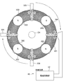
- FIG. 11 to 16 are schematic diagrams for explaining the motor according to the fifth embodiment, and the casing supporting the stator and the output shaft, and supporting the sensor unit and the like is a diagram. Not shown. Also, a housing for holding the permanent magnets of the rotor and rotating about the rotation axis is not shown. Furthermore, since the same thing can be used for the excitation circuit part 42 (refer FIG. 2), description is abbreviate
- either the N pole or the S pole of the cylindrical permanent magnet 202 of the rotor 200 corresponds to the rotation axis L1 of the rotor 200.
- the stator 300 is oriented along the rotation circumference R1 in the direction in which the magnetic poles of the rotor 200 are directed.
- the rotor 200 is disposed on both sides in the vertical direction, sandwiching the stator 300, and is connected to the output shaft O1.
- the rotor 200 is three in the upper and lower stages (first rotor 200a), middle stage (second rotor 200b), and lower stage (third rotor 200c) along the vertical direction. Is equipped.
- stator 300 two stators 300, the upper stage (first stator 300a) and the lower stage (second stator 300b), are disposed between the respective rotors 200. Therefore, the upper stator 300 (first stator 300a) is sandwiched by the upper and middle rotors 200 (first rotor 200a and second rotor 200b), and the lower stator 300 (second The stator 300b) is sandwiched by the middle and lower rotors 200 (the second rotor 200b and the third rotor 200c).
- Each permanent magnet 202 of the rotor 200 is disposed at the same position as viewed from the direction along the rotation axis L1.
- the upper rotor 200 (first rotor 200 a) is disposed such that the N pole and the S pole of the permanent magnet 202 alternately face the lower stator 300.
- the magnetic poles (the magnetic poles facing the permanent magnets 202 of the upper rotor 200) in the middle rotor 200 (the second rotor 200b) are arranged to have the same polarity as the upper rotor 200.
- the downward facing magnetic pole of the middle stage rotor 200 is the opposite magnetic pole to the upward facing magnetic pole of the middle stage rotor 200.
- the upward facing magnetic pole (the magnetic pole facing the permanent magnet 202 of the middle stage rotor 200) in the lower stage rotor 200 (third rotor 200c) is the same pole as the downward direction pole in the middle stage rotor 200. It is arranged.
- a plurality of windings 301 to 304 of the stator 300 are provided along the rotation axis L1, and each of the upper stator 300 (first stator 300a) and the lower stator 300 (second stator 300b) is The gaps between the windings 301 to 304 are arranged at positions shifted by 45 degrees in the circumferential direction of rotation.
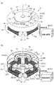
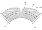
- the stator 300 is formed by winding arc-shaped windings 301 to 304 whose circumference is divided into four along the circumferential direction around the rotation axis L1 of the rotor 200, as shown in FIG. ing.
- the core 310 shown in FIG. 12 is formed of a disk-shaped collar portion 311 located at both ends and a core member 312 which connects the collar portions 311 and around which the windings 301 to 304 are wound. ing.
- the core 310 can be made of metal or resin. When the core 310 is made of resin, magnetic saturation does not occur, which is preferable when a large current flows in the windings 301 to 304.
- the stators 300 are connected in series by the respective windings 301 to 304 being connected by connection wires 305.
- the wirings from both ends of the stator 300 (windings 301 to 304) connected in series are connected to the excitation circuit unit 42 of the control circuit 40.
- the windings 301 to 304 of the stator 300 are wired by the excitation circuit unit 42 so that the facing ends generate the same pole.
- the sensor unit (not shown) is provided with a transmission type photo interrupter and a shielding plate having a notch passing through the photo interrupter. Can.
- the position of the permanent magnet 202 of the rotor 200 can be detected.
- the stator 300 since the stator 300 includes the four windings 301 to 304, and the first stator 300a and the second stator 300b are displaced by 45 degrees along the rotation circumference, the coils 300 are wound. It is formed to detect four places where the ends of the lines 301 to 304 face each other.
- the permanent magnet 202 is the winding 301 of the upper stator 300 (first stator 300a).
- the permanent magnet 202 is the lower stage stator 300 (the second stator It is located near the end of the winding 301-304 of 300b).
- the exciting circuit unit 42 has an N pole at the end where the winding 301 and the winding 302 face each other, and an end where the winding 302 and the winding 303 face each other.
- the electrodes are energized such that the ends are S poles, the ends where the windings 303 and 304 face each other are N poles, and the ends where the ends of the windings 304 and 301 face each other are S poles. Further, as shown in FIG.
- the exciting circuit unit 42 has the end portions where the winding 301 and the winding 302 face each other as S poles, and the winding 302
- the ends facing winding 303 are N poles
- the ends facing windings 303 and 304 are S poles
- the ends facing winding 304 and winding 301 are N poles.
- the middle and lower rotors 200 and the lower stator 300 are positioned so that the same poles face each other, so they repel and rotate.
- the sensor unit detects that the upper and middle permanent magnets 202 approach the end of the windings 301 to 304 after the rotor 200 repels the stator 300 and rotates 45 °
- the excitation circuit unit 42 The magnetic poles of the windings 301 to 304 are reversed by reversing the current directions of the upper stator 300 and the lower stator 300.
- stator 300 when the middle and lower rotors 200 repel the lower stator 300, the stator 300 reverses the magnetic poles, and when the upper and middle rotors 200 repel the upper stator 300, the stator 300 rotates. Reverses the magnetic pole. By repeating this, the rotor 200 can keep rotating.
- one of the N pole and the S pole of the permanent magnet 202 is directed along the rotation axis L1 of the rotor 200, and the stator 300 is rotated. It arrange
- the permanent magnet 202 of the rotor 200 shown in FIG. 11 faces in the direction along the rotation axis L1, and the stator 300 is permanent.
- the winding C1 is disposed along the rotation circumference R1 in the direction in which the magnetic poles of the magnet 202 are directed. Therefore, the permanent magnet 202 housed in the housing (not shown) has different directions from the direction in which the centrifugal force acts and the direction in which the windings 301 to 304 are approached. Even if the rotor 200 is rotated at high speed by being placed in the housing in proximity to the housing 304, the permanent magnet 202 does not jump out of the housing. Therefore, long-time operation can be enabled while maintaining the high speed rotation of the rotor 200.
- the gaps between the windings 301 to 304 are arranged at positions shifted by 45 degrees along the circumferential direction between the first stator 300a and the second stator 300b. Therefore, even if the rotor 200 attempts to decelerate or stop at the gap between the ends of the stator 300, it can be rotationally driven by the other stator 300. Therefore, rotation can be continued without the rotor 200 decelerating.
- FIG. 17 the same components as those in FIG. 5 (B) are assigned the same reference numerals and explanation thereof is omitted.
- the winding C2 of the stator 30b surrounding the output shaft O1, which is the rotation center of the rotor 20, is the same as the motor 11 of the second embodiment. It arrange
- the winding C2 is electrically connected in parallel in a state in which two parallel coils are arranged in the radial direction of the rotation circumference R1.
- the resistance value of the stator 30b can be suppressed to a low value by connecting in parallel a plurality of windings C2 of the stator 30b in which the axis L2 is linearly formed. Therefore, when the number of windings C2 is one or more than two, a larger amount of current can flow, so that the driving force of the rotor 20 can be increased.
- the stator 30b is formed by the two sets of windings C2 in the sixth embodiment, but three or more may be set as one set. Further, a plurality of windings C2 may be disposed along the rotation axis L1 of the output shaft O1.
- the first winding 31 to the fourth winding 34 shown in FIGS. 1, 5, 6, 7, 8, 11, 11 and 17 are used as the stator. It is formed by lines 301 to 304, but it is formed in an annular shape by forming a pair of windings with a half circumference, three windings at every 120 degrees, or five or more windings. May be In any case, the winding direction and the current flow direction are controlled so that the ends of adjacent windings generate the same pole.
- rotational speed adjustment unit 50 shown in FIG. 9 includes rectification unit 51
- consumption unit 52 can be used if electric power from power generation windings 35a to 35d can be consumed as it is. It may be directly connected to the power generation windings 35a to 35d.
- straight tubular windings 33a to 33d are the motor 12 according to the second embodiment shown in FIG. 2 (A), the motor 14 according to the fifth embodiment shown in FIG. 11, and the motor according to the fifth embodiment shown in FIG. 15 and the motor 16 shown in FIG.
- the stator 300 is provided in two stages of upper and lower stages, and the rotor 200 is provided in three stages so as to sandwich the stator 300.
- the number of the rotors 200 and the number of the stators 300 may be the same or one rotor 200 each.
- the permanent magnet 202 is formed in a cylindrical shape, but may be formed in a spherical shape.
- the winding C2 of the motor 11 shown in FIG. 5 has a linear axis L2 and a circular cross section orthogonal to the axis L2.
- the line C3 can also be formed such that the axis L3 is linear and the cross section orthogonal to the axis L3 is elliptical.
- a pair of rotors 20 is provided with the stator 320 interposed therebetween.
- the winding C3 is formed in an elliptical shape in which the direction of the rotation axis L1 is crushed, when the rotor 20 is disposed on both sides of the stator 320, the cross section has a circular shape.
- the permanent magnets 22 can be arranged close to each other. Therefore, since the magnetic poles of the permanent magnets 22 can be disposed close to the axis L3 of the winding C3 where the magnetic force becomes strong, the rotational force of the rotor 20 can be increased.
- the rotor 20 is provided on both sides of the stator 320 in the present embodiment, either of the stators 320 may be provided.
- the winding only needs to be able to bring the magnetic pole of the permanent magnet 22 closer to the axis of the winding, so the section of the winding has a length (thickness) in the direction along the rotation axis L1 It may be formed shorter than the radial length (width) of R1. Therefore, the cross-sectional thickness of the winding may be smaller than the width, such as a rectangle, a rhombus, or another polygonal shape.
- the axis L3 of the winding C3 is formed in a linear shape, but even if the winding C1 shown in FIG. 1 is an arc, the direction of the rotation axis L1 of the winding C1 is collapsed. It can also be shaped. Further, as in the motor 15 shown in FIG. 17, a plurality of windings C1 may be provided in parallel.
- the rotary electric machine according to the present invention was manufactured to operate as a generator, and the generated power was measured.
- the generator of this embodiment is a multistage generator such as the motor 14 shown in FIG.
- one stage is constituted by four windings and arranged in three stages.
- the winding was a core of 10 mm in diameter and 80 mm in length and a copper wire of 0.7 mm in thickness. The number of turns is 970 turns.
- the permanent magnet of the rotor employed a neodymium magnet having a magnetic grade of N52.
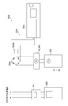
- the measurement system 500 is for driving a power meter 501 for measuring input power, an inverter 502 for adjusting voltage and frequency, and a generator G2 of a comparative product for comparison with the generator G1 of the invention and the invention.
- the motor 503 and the load unit 504 are provided.
- the load unit 504 includes a diode bridge 504a for full-wave rectifying the output from the generator of the invention, a capacitor 504b for smoothing the pulsating current from the diode bridge 504a, and an electronic load device 504c whose power consumption can be adjusted. There is.
- the electronic load device 504c LN-1000C-G7 manufactured by Gaiken Giken Co., Ltd. was used.
- the comparison product G2 is MCT-500 manufactured by Nidec Corporation.
- the input power and the output power of the inventive generator G1 and the comparative product G2 were measured, summarized in a table, and a graph was created.
- the power obtained by subtracting the power consumption when the electronic load device 504c is brought into the load state (open state) from the power (total power consumption) measured by the power meter 501 is the input power. did. Therefore, the input power is 0 W when the electronic load device 504 c is in the load state (open state).
- the generator G1 which is an inventive product, has a higher generating power than the generator G2, which is a comparative product. Therefore, it is understood that the rotary electric machine of the present invention not only functions as a motor, but also sufficiently functions as a generator.
- the present invention is suitable for any machine in which an electric motor is used because the driving force can be obtained efficiently by a plurality of rotors.
Landscapes
- Engineering & Computer Science (AREA)
- Power Engineering (AREA)
- Microelectronics & Electronic Packaging (AREA)
- Physics & Mathematics (AREA)
- Electromagnetism (AREA)
- Permanent Magnet Type Synchronous Machine (AREA)
- Permanent Field Magnets Of Synchronous Machinery (AREA)
Abstract
Description
しかし、ロータ磁石の磁極をステータのコイルに向け、ロータ部のハウジングに回転円周に沿って複数のロータ磁石を収納して回転させるときには、ロータ部が高速回転すると、ハウジングから磁石が、遠心力によりコイルの方向へ飛び出すおそれがある。
そのため、ハウジングに収納された永久磁石は、遠心力が作用する方向と、磁極が巻線へ向く方向とが異なるので、永久磁石を巻線へ接近させてハウジングに配置して、回転子を高速に回転させても、永久磁石をハウジングから飛び出し難くすることができる。また、回転子が固定子の端部同士の隙間にて減速又は停止しようとしても、他の固定子にて回転駆動を付与することができる。
そのため、ハウジングに収納された永久磁石は、遠心力が作用する方向と、磁極が巻線へ向く方向とが異なるので、永久磁石を巻線へ接近させてハウジングに配置して、回転子を高速に回転させても、永久磁石をハウジングから飛び出し難くすることができる。また、複数の巻線の端部同士の間で発生する磁力を、補助用の巻線により補完させることができるので、補助用の巻線により、回転子の回転駆動力を増強することができる。
発電用巻線は、補助用の巻線と同軸であるため、発電用巻線に発生する磁界が補助用の巻線を助勢するように作用する。従って、回転速度調整部に流れる電流に応じて永久磁石の回転数を調整することができる。
従って、本発明の回転電機は、逆起電力の発生を抑えることにより、高電圧を印加しなくても高回転とすることができ、高回転を長時間続けても回転子の信頼性を維持することができる。
20,200 回転子
200a 第1回転子
200b 第2回転子
200c 第3回転子
21 ハウジング
22,202 永久磁石 30,30a,30b,300,320 固定子
300a 第1固定子
300b 第2固定子
301~304 巻線
310 コア
311 鍔部
312 芯材
305 接続線
31~34 第1巻線~第4巻線
31T1,31T2,32T1,32T2,33T1,33T1,33T2,34T1,34T2 端部
33a~33d 巻線
35a~35d 発電用巻線
40 制御回路
41 センサ部
411 第1センサ部
412 第2センサ部
41a フォトインタラプタ
41b 遮蔽板
41c 円弧状切欠部
42 励磁回路部
421a,421b 第1FET
422a,422b 第2FET
423a,423b 第3FET
G ゲート端子
S ソース端子
D ドレイン端子
R11,R12,R21,R22,R31,R32,R41,R42 抵抗
C11,C12 コンデンサ
D11,D12,D21,D22 ダイオード
50 回転速度調整部
51 整流部
52 消費部
C1,C2,C3 巻線
O1 出力軸
R1 回転円周
F1 主磁束方向
L1 回転軸線
L2,L3 軸線
R 磁路
S1 隙間
G1 発電機(発明品)
G2 発電機(比較品)
500 測定システム
501 電力計
502 インバータ
503 電動機
504負荷部
504a ダイオードブリッジ
504b コンデンサ
504c 電子負荷装置
本発明の実施の形態1に係る回転電機について、電動機を例に、図面に基づいて説明する。
なお、図1(A)及び同図(B)は本実施の形態1に係る電動機を説明するための概略図であり、固定子や出力軸を支持したり、センサ部などを支持したりする筐体は図示していない。
図1(A)及び同図(B)に示す電動機10は、出力軸O1と同軸に形成された回転子20と、回転子20を回転駆動する磁束を励磁する固定子30とを備えている。
ハウジング21は、円盤状に形成され、永久磁石22を回転円周R1に沿って等間隔に収納するものである。
永久磁石22は、直方体に形成され、N極またはS極のいずれか一方の磁極を交互に固定子30に向けてハウジング21に配置されている。本実施の形態1では、永久磁石22が90度ごとに4個、ハウジング21に設けられている。
永久磁石22は、磁力が他の磁石より強いネオジム磁石が使用できる。
固定子30は、回転子20が巻線C1の端部(端部31T1,31T2,32T1,32T2,33T1,33T2,34T1,34T2)に向いたときに、巻線C1の端部から巻線内への磁路R(図4参照)が、回転子20からの主磁束方向F1と交差する方向に形成されている。
本実施の形態1では、固定子30は、回転子20の回転軸線L1を中心として、巻線C1が回転円周R1に沿った円弧状に形成されている。
第1巻線31~第4巻線34の巻線C1は、通電すると、向き合う一方の端部31T1,34T1同士、端部32T1,33T1同士が同極に、他方の端部31T2,32T2同士、端部33T2,34T2同士が同極を発生するように配線が巻かれている。
センサ部41は、一方の端部31T1,34T1と、端部32T1,33T1とをN極とし、他方の端部31T2,32T2と、端部33T2,34T2とをS極とするタイミングを検出したり、反対に、一方の端部31T1,34T1と、端部32T1,33T1とをS極とし、他方の端部31T2,32T2と、端部33T2,34T2とをN極とするタイミングを検出したりするために、第1センサ部411と、第2センサ部412とを備えている。
フォトインタラプタ41aは、第1巻線31と第4巻線34とが向き合う一方の端部31T1,34T1の位置を0度の位置、第2巻線32と第3巻線33が向き合う一方の端部32T1,33T1の位置を180度の位置としたときに、0度と90度の位置に形成されている。
励磁回路部42は、第1センサ部411と第2センサ部412とを一組として、第1FET421a,421bから第3FET423a,423bまでのトランジスタにより、第1巻線31~第4巻線34への通電方向を制御する。
第1FET421a,421bは、ゲート端子Gが抵抗R11,R12を介してフォトインタラプタ41aに接続されている。また、第1FET421a,421bは、ソース端子Sが接地されている。
第4巻線34の一方の端部34T1からの配線は、第2FET422aのドレイン端子Dに接続されていると共に、第3FET423aのドレイン端子Dに接続されている。
第1巻線31の一方の端部31T1からの配線は、第2FET422bのドレイン端子Dに接続されていると共に、第3FET423bのドレイン端子Dに接続されている。
図1(A)および同図(B)に示す制御回路40に電源が供給される。
例えば、永久磁石22のN極が、第1センサ部411のフォトインタラプタ41aの方向へ向くと、第1センサ部411のフォトインタラプタ41aに遮蔽板41bの円弧状切欠部41cが位置する。
遮蔽板41bの円弧状切欠部41cにより、第1センサ部411のフォトインタラプタ41aの光が透過することで、第1センサ部411のフォトインタラプタ41aのフォトトランジスタが通電する。
従って、図2に示すように、第2センサ部412のフォトインタラプタ41aに、抵抗R12,R42を介して接続された第1FET421bのゲート端子Gと、第3FET423bのゲート端子Gとは、第1FET421bと第3FET423bがオフ状態となる、第1電圧より低電圧の第2電圧(0V)となる。
そして、電流が、第1巻線31から第2巻線32、第3巻線33および第4巻線34へ順次流れ、第4巻線34の一方の端部34T1から第3FET423aのドレイン端子Dへ流れ、第3FET423aのドレイン端子Dからソース端子Sへ流れる。
そうすることで、図3(A)に示すように、第1巻線31の端部31T1,第4巻線34の端部34T1と、第2巻線32の端部32T1,第3巻線33の端部33T1とに、永久磁石22のN極と反発する同極(N極)の磁界が発生し、他方の端部31T2,端部32T2と、端部33T2,端部34T2とに、永久磁石22のS極と反発する同極(S極)の磁界が発生する。
第1巻線31~第4巻線34が発生した磁界により、永久磁石22の両極が反発して、回転子20が回転する。
遮蔽板41bの円弧状切欠部41cにより、第2センサ部412のフォトインタラプタ41aの光が透過することで、第2センサ部412のフォトインタラプタ41aのフォトトランジスタが通電する。
そして、電流が、第4巻線34から第3巻線33、第2巻線32および第1巻線31へと順次流れ、第1巻線31の一方の端部31T1から第3FET423bのドレイン端子Dへ流れ、第3FET423bのドレイン端子Dからソース端子Sへ流れる。
そうすることで、図3(B)に示すように、第1巻線31の端部31T1,第4巻線34の端部34T1と、第2巻線32の端部32T1,第3巻線33の端部33T1とに、永久磁石22のS極と反発する同極(S極)の磁界が発生し、他方の端部31T2,端部32T2と、端部33T2,端部34T2とに、永久磁石22のN極と反発する同極(N極)の磁界が発生する。
第1巻線31~第4巻線34が発生した磁界により、永久磁石22の両極が反発して、回転子20が回転する。
このように、固定子30において、図3(A)に示す磁極と図3(B)に示す磁極とが交互に発生することで、回転子20は回転し続けることができる。
そのため、図4に示すように固定子30内の磁路は、巻線(第1巻線31~第4巻線34)の円弧状に沿ったものとなる。回転子20の永久磁石22の各磁極が第1巻線31~第4巻線34の端部(図4では第1巻線31の端部31T1,第4巻線34の34T1)を向いて通過するときには、固定子30の端部から固定子30内への磁路が、回転子20からの主磁束方向F1と交差する方向となる。
従って、回転子20からの主磁束は、巻線C1の筒内に真っ直ぐ入るように横切らない。よって、電動機10は、巻線の向きを半径方向に向けた従来の電動機より磁束の変化が小さいので、従来の電動機より逆起電力を小さいものとすることができる。
そのため、ハウジング21に収納された永久磁石22は、遠心力が作用する方向(回転円周R1の半径方向)と、磁極が巻線C1に向く方向とが異なる方向となるので、永久磁石22を巻線C1へ接近させてハウジング21に配置して、回転子20を高速に回転させても、ハウジング21から永久磁石22を飛び出し難くすることができる。
従って、回転子20の高速回転を維持した状態で長時間の運転を可能とすることができる。
本発明の実施の形態2に係る回転電機について、電動機を例に、図面に基づいて説明する。なお、図1(A)及び同図(B)と同様に、図5(A)及び同図(B)においても、固定子や出力軸、センサ部などを支持する筐体は図示していない。また、図5(A)及び同図(B)においては、図1(A)及び同図(B)と同じ構成のものは、同符号を付して説明を省略する。
このように固定子30aの巻線C2の軸線L2が直線状に形成されていても、永久磁石22が巻線C2の端部に向いたときに、巻線C2の端部から巻線C2内への磁路が、永久磁石22からの主磁束方向と交差する方向に、固定子30aの巻線C2が形成されており、そして、永久磁石22の磁極が向く方向における回転円周R1に沿って巻線C2が配置されている。そのため、実施の形態1と同じ作用・効果を得ることができる。
しかし、電動機11では、回転円周R1に沿って配置された巻線C2の上方を、回転子20の永久磁石22が回転するため、永久磁石22の磁極と巻線C2との距離を一定とすることができる。
本発明の実施の形態3に係る回転電機について、電動機を例に、図面に基づいて説明する。図6に示す本実施の形態3に係る電動機12は、図1(A)及び同図(B)に示す実施の形態1に係る電動機10に、補助用の巻線33a~33dを備えたものである。
なお、図6においては、図1(A)及び同図(B)と同じ構成のものは、同符号を付して説明を省略する。
巻線33aは、端部31T1及び端部34T1と同極となるように、巻線33bは、端部31T2及び端部32T2と同極となるように、また、巻線33cは、端部32T1及び端部32T1と同極となるように、更に、巻線33dは、端部33T2及び端部34T21と同極となるように、制御回路40により制御される。
従って、巻線33a~33dにより、回転子20の回転駆動力を増強することができる。
本実施の形態3に係る電動機の変形例を、図面に基づいて説明する。
図7に示す本実施の形態3に係る電動機12aは、図6に示す実施の形態3に係る電動機12に対して、補助用の巻線33a~33dの軸線L3を回転軸線L1に沿って回転子20側に向けたものであり、固定子30aの巻線C2が、直線状の軸線L2に形成されたものである。
なお、図7においては、図5(A)及び同図(B)および図6と同じ構成のものは、同符号を付して説明を省略する。
本発明の実施の形態4に係る回転電機について、電動機を例に、図面に基づいて説明する。図8に示す本実施の形態4に係る電動機13は、図6に示す実施の形態3に係る電動機12に、発電用巻線35a~35dを備えたものである。
なお、図8においては、図6と同じ構成のものは、同符号を付して説明を省略する。
発電用巻線35a~35dには、図9に示すように、回転速度調整部50が接続されている。
回転速度調整部50は、整流部51と、消費部52とを備えている。整流部51は、ダイオードブリッジにより構成することができる。
消費部52は、可変抵抗器とすることができるが、可変抵抗器の代わりに電気エネルギーを有効利用する負荷を接続してもよい。例えば、バッテリの充電回路としたり、照明器具としたり、電動機としたりすることができる。消費部52は、短絡状態から開放状態までに抵抗値を設定できるものとすることができる。
回転速度調整部50は、発電用巻線35a~35dのそれぞれに設けることができ、また、発電用巻線35a~35dに共通させて設けることもできる。
図8に示す電動機13を動作させ、巻線33a~33dに通電することで発電用巻線35a~35dに起電力を発生させることができる。図9に示す発電用巻線35a~35dからの電流は整流部51により全波整流され、消費部52に流れる。消費部52では、発電用巻線35a~35dからの電力を、設定された抵抗値によって消費する。
本実施の形態4に係る電動機の変形例を、図面に基づいて説明する。
図10に示す本実施の形態4に係る電動機13aは、図8に示す実施の形態4に係る電動機12に対して、補助用の巻線33a~33dおよび発電用巻線35a~35dの軸線L3を回転軸線L1に沿って回転子20側に向けたものであり、固定子30aの巻線C2が、直線状の軸線L2に形成されたものである。
なお、図10においては、図5(A)及び同図(B)および図8と同じ構成のものは、同符号を付して説明を省略する。
本発明の実施の形態5に係る回転電機について、電動機を例に、図面に基づいて説明する。
なお、図11から図16においては、本実施の形態5に係る電動機を説明するための概略図であり、固定子や出力軸を支持したり、センサ部などを支持したりする筐体は図示していない。また、回転子の永久磁石を保持して回転軸線を中心に回転させるハウジングは図示していない。更に、励磁回路部42(図2参照)は、同様のものが使用できるため、説明は省略する。
回転子200は、固定子300を挟んで、上下方向の両側に配置され、出力軸O1に接続されている。本実施の形態5に係る電動機14では、回転子200が上下方向に沿って、上段(第1回転子200a)、中段(第2回転子200b)、下段(第3回転子200c)の3つを備えている。そのため、それぞれの回転子200の間に固定子300が上段(第1固定子300a)及び下段(第2固定子300b)の2つ配置されている。
従って、上段の固定子300(第1固定子300a)は、上段および中段の回転子200(第1回転子200a,第2回転子200b)によって挟まれており、下段の固定子300(第2固定子300b)は、中段及び下段の回転子200(第2回転子200b,第3回転子200c)によって挟まれている。
上段の回転子200(第1回転子200a)は、永久磁石202のN極とS極が交互に下方の固定子300に向くように配置されている。
中段の回転子200(第2回転子200b)における上方を向く磁極(上段の回転子200の永久磁石202と向き合う磁極)は、上段の回転子200と同極になるように配置されている。また、中段の回転子200の下方の向く磁極は、中段の回転子200の上方を向く磁極と反対の磁極である。
下段の回転子200(第3回転子200c)における上方を向く磁極(中段の回転子200の永久磁石202と向き合う磁極)は、中段の回転子200における下方を向く磁極と同極になるように配置されている。
固定子300は、回転子200の回転軸線L1を中心に円周方向に沿って円周を4分割した円弧状の巻線301~304が、図12に示すコア310に巻き回されて形成されている。
コア310は、金属製とすることもできるが樹脂製とすることもできる。コア310を樹脂製とすれば磁気飽和が生じないので、巻線301~304に大電流を流すときには好ましい。
固定子300の巻線301~304は、励磁回路部42により、向き合う端部同士が同極を発生するように配線が巻かれている。
図13及び図14に示すように、まず、初期状態として、上段の回転子200(第1回転子200a)は、永久磁石202が上段の固定子300(第1固定子300a)の巻線301~304の中央部付近に位置しているが、中段の回転子(第2回転子200b)及び下段の(第3回転子200c)は、永久磁石202が下段の固定子300(第2固定子300b)の巻線301~304の端部付近に位置している。
また、励磁回路部42は、図13に示すように、下段の固定子300(第2固定子300b)について、巻線301と巻線302とが向き合う端部同士がS極、巻線302と巻線303とが向き合う端部同士がN極、巻線303と巻線304とが向き合う端部同士がS極、巻線304と巻線301とが向き合う端部同士がN極となるように通電する。
回転子200が固定子300に反発して45°回転して、上段及び中段の永久磁石202が巻線301~304の端部への接近したことをセンサ部が検知すると、励磁回路部42は、上段の固定子300と下段の固定子300の電流の向きを反転させることで、巻線301~304のそれぞれの磁極が反転する。
そのため、巻線301~304の端部同士が向き合い、回転子200の永久磁石202の方向を向いていないので、永久磁石202からの主磁束が、巻線301~304の筒内に真っ直ぐ入るように横切らない。
従って、電動機14は、従来の発電機として動作する電動機より、起電力が小さいので、従来のものより逆起電力を小さくすることができる。よって、電動機14は、同じ回転数であれば、低い電圧で回転駆動させることができ、同じ電圧であれば、高速に回転させることができる。
そのため、ハウジング(図示せず)に収納された永久磁石202は、遠心力が作用する方向と、巻線301~304に接近させる方向とが異なる方向となるため、永久磁石202を巻線301~304へ接近させてハウジングに配置して、回転子200を高速に回転させても、ハウジングから永久磁石202が飛び出してしまうことは無い。
従って、回転子200の高速回転を維持した状態で長時間の運転を可能とすることができる。
本発明の実施の形態6に係る回転電機について、電動機を例に、図面に基づいて説明する。なお、図17においては、図5(B)と同じ構成のものは同符号を付して説明を省略する。
図17に示す本実施の形態6に係る電動機15は、回転子20の回転中心となる出力軸O1を中心に取り囲む固定子30bの巻線C2が、実施の形態2の電動機11と同様に、永久磁石22の磁極が向く方向における回転円周R1に沿って配置されており、回転子20の回転円周R1の接線に沿った軸線L2が直線状に形成されている。そして、巻線C2は、平行した2本が回転円周R1の半径方向に並べられた状態で、電気的に並列接続されている。
従って、巻線C2を1本としたときと複数本としたときの方が電流を多く流すことができるため、回転子20の駆動力を増強することができる。
いずれの場合でも、隣接する巻線の端部が同極を発生するように巻方向及び通電方向を制御する。
また、実施の形態4では、図9に示す回転速度調整部50が整流部51を備えているが、発電用巻線35a~35dからの電力をそのまま消費できるのであれば、消費部52を、発電用巻線35a~35dに、直接接続してもよい。
また、実施の形態3に係る電動機12の直管状の巻線33a~33d(図6参照)、実施の形態に4に係る電動機13の直管状の巻線33a~33d及び発電用巻線35a~35d(図8参照)は、図2(A)に示す実施の形態2に係る電動機12と、図11に示す実施の形態5に係る電動機14と、図17に示す実施の形態5に係る電動機15と、図18に示す電動機16とに設けることもできる。
更に、本実施の形態5では、永久磁石202が円柱状に形成されているが球状に形成されていてもよい。
また、回転子20は、固定子320を挟んで一対設けられている。
従って、磁力が強くなる巻線C3の軸線L3に接近させて、永久磁石22の磁極を配置することができるため、回転子20の回転力を増加させることができる。
また、巻線は、永久磁石22の磁極を、巻線の軸線に接近させることができればよいので、巻線の断面は、回転軸線L1に沿った方向の長さ(厚み)が、回転円周R1の半径方向の長さ(幅)より、短く形成されていればよい。従って、巻線の断面の厚みが幅より薄い、長方形や菱形、その他の多角形状とすることもできる。
また、図18では、巻線C3の軸線L3が直線状に形成されているが、図1に示す巻線C1が円弧状であっても、この巻線C1を回転軸線L1の方向が潰れた形状とすることもできる。また、図17に示す電動機15のように巻線C1を平行に複数本設けてもよい。
本発明に係る回転電気を製作して発電機として動作させ、発電電力を測定した。
本実施例の発電機は、図11に示す電動機14のような多段式の発電機とした。
発明品としての発電機の固定子は、1段を4個の巻線により構成し、3段配置したものとした。
巻線は、直径10mmで長さが80mmのコアに、太さが0.7mmの銅線を巻いたものとした。巻数は970ターンである。
回転子の永久磁石は、磁力の等級がN52のネオジム磁石を採用した。
測定システム500は、入力電力を測定する電力計501と、電圧および周波数を調整するインバータ502と、発明品である発電機G1および発明品と比較するための比較品の発電機G2を駆動するための電動機503と、負荷部504とを備えている。
インバータ502は、三菱電機社のFR‐A820-1.5K-1を使用した。
電動機503は、東芝社のIKH3-FCKLA21E-4P-1.5KW-220を使用した。
負荷部504は、発明品の発電機からの出力を全波整流するダイオードブリッジ504aと、ダイオードブリッジ504aからの脈流を平滑するコンデンサ504bと、消費電力は調整できる電子負荷装置504cとを備えている。
電子負荷装置504cは、計測技研社のLN‐1000C‐G7を使用した。
比較品G2は、日本電産社のMCT-500である。
なお、図20に示す表では、電力計501にて測定された電力(総消費電力)から、電子負荷装置504cを負荷状態(開放状態)としたときの消費電力を差し引いた電力を入力電力とした。従って、電子負荷装置504cを負荷状態(開放状態)としたときの入力電力は0Wとなる。
そして、発電機G1の発電電力を測定するために、発電機G1への入力電力を徐々に上げて発電電力を測定し終わった後に、発電機G1の発電電力を測定したときの入力電力に、発電機G2への入力電力を合わせて徐々に上げて、発電機G2への発電電力を測定した。
従って、本発明の回転電機は、電動機として機能するだけでなく、発電機としても十分に機能を発揮することが判る。
Claims (10)
- 複数の永久磁石がハウジングに回転円周に沿って配置され、前記永久磁石の磁極が回転軸線に沿った方向に向いた回転子と、
回転円周に沿って配置された複数の巻線を有する固定子とを備え、
前記巻線は、前記永久磁石の磁極が前記巻線に向いたときに、前記巻線の端部から巻線内への磁路が、前記永久磁石からの主磁束方向と交差する方向に形成され、
前記固定子は、前記回転子の回転軸線に沿って複数備えられ、
前記固定子のそれぞれは、前記固定子を形成する巻線同士の隙間が、回転円周方向にずれた位置に配置された回転電機。 - 複数の永久磁石がハウジングに回転円周に沿って配置され、前記永久磁石の磁極が回転軸線に沿った方向に向いた回転子と、
回転円周に沿って配置された複数の巻線を有する固定子とを備え、
前記巻線は、前記永久磁石の磁極が前記巻線に向いたときに、前記巻線の端部から巻線内への磁路が、前記永久磁石からの主磁束方向と交差する方向に形成され、
前記複数の巻線の端部同士の間に、補助用の巻線が設けられた回転電機。 - 前記回転子は、前記固定子を挟んで両側に配置された請求項1又は2記載の回転電機。
- 前記固定子は、前記回転子の回転円周に沿った円弧状の前記巻線により形成された請求項1から3のいずれかの項に記載の回転電機。
- 前記固定子は、前記回転子の回転円周の接線に沿った軸線が直線状の前記巻線により形成された請求項1から3のいずれかの項に記載の回転電機。
- 前記固定子は、前記回転子の回転中心を取り囲む巻線が並列接続された複数本により形成された請求項1から5のいずれかの項に記載の回転電機。
- 前記巻線の断面は、回転軸線に沿った方向の長さが、回転円周の半径方向の長さより、短く形成された請求項1から6のいずれかの項に記載の回転電機。
- 前記補助用の巻線と同軸に、発電用巻線が設けられた請求項2記載の回転電機。
- 前記発電用巻線からの電流を調整する回転速度調整部が接続されている請求項8記載の回転電機。
- 前記回転速度調整部は、前記発電用巻線に接続された整流部と、前記整流部からの電流を消費する消費部とを備えた請求項9記載の回転電機。
Priority Applications (9)
| Application Number | Priority Date | Filing Date | Title |
|---|---|---|---|
| EP18842245.5A EP3648320A4 (en) | 2017-08-03 | 2018-07-25 | DYNAMO-ELECTRIC MACHINE |
| AU2018309956A AU2018309956B2 (en) | 2017-08-03 | 2018-07-25 | Rotary Electric Machine |
| US16/636,327 US11482914B2 (en) | 2017-08-03 | 2018-07-25 | Rotary electric machine |
| KR1020207003202A KR102373398B1 (ko) | 2017-08-03 | 2018-07-25 | 회전 전기 |
| CN202210131338.5A CN114465375A (zh) | 2017-08-03 | 2018-07-25 | 旋转电机 |
| CN201880048429.4A CN110945763B (zh) | 2017-08-03 | 2018-07-25 | 旋转电机 |
| CA3070354A CA3070354C (en) | 2017-08-03 | 2018-07-25 | Rotary electric machine |
| MYPI2020000491A MY187170A (en) | 2017-08-03 | 2018-07-25 | Rotary electric machine |
| PH12020500229A PH12020500229A1 (en) | 2017-08-03 | 2020-01-30 | Rotary electric machine |
Applications Claiming Priority (4)
| Application Number | Priority Date | Filing Date | Title |
|---|---|---|---|
| JP2017150676 | 2017-08-03 | ||
| JP2017-150676 | 2017-08-03 | ||
| JP2017-221198 | 2017-11-16 | ||
| JP2017221198A JP6359747B1 (ja) | 2017-08-03 | 2017-11-16 | 回転電機 |
Publications (1)
| Publication Number | Publication Date |
|---|---|
| WO2019026725A1 true WO2019026725A1 (ja) | 2019-02-07 |
Family
ID=62904881
Family Applications (1)
| Application Number | Title | Priority Date | Filing Date |
|---|---|---|---|
| PCT/JP2018/027897 WO2019026725A1 (ja) | 2017-08-03 | 2018-07-25 | 回転電機 |
Country Status (10)
| Country | Link |
|---|---|
| US (1) | US11482914B2 (ja) |
| EP (1) | EP3648320A4 (ja) |
| JP (1) | JP6359747B1 (ja) |
| KR (1) | KR102373398B1 (ja) |
| CN (2) | CN110945763B (ja) |
| AU (1) | AU2018309956B2 (ja) |
| CA (1) | CA3070354C (ja) |
| MY (1) | MY187170A (ja) |
| PH (1) | PH12020500229A1 (ja) |
| WO (1) | WO2019026725A1 (ja) |
Families Citing this family (1)
| Publication number | Priority date | Publication date | Assignee | Title |
|---|---|---|---|---|
| US11901780B2 (en) * | 2020-12-11 | 2024-02-13 | Mabuchi Motor Co., Ltd. | Resolver |
Citations (7)
| Publication number | Priority date | Publication date | Assignee | Title |
|---|---|---|---|---|
| JPS60226751A (ja) | 1984-04-25 | 1985-11-12 | Matsushita Electric Ind Co Ltd | 永久磁石回転子型同期電動機 |
| JP2000184627A (ja) | 1998-12-10 | 2000-06-30 | Minebea Co Ltd | トロイダルコア型アクチュエータ |
| JP2006238623A (ja) * | 2005-02-25 | 2006-09-07 | Fujitsu General Ltd | 直流モータ |
| JP2013021888A (ja) * | 2011-07-14 | 2013-01-31 | Shinsei Shoji Co Ltd | 発電装置 |
| JP2014135852A (ja) | 2013-01-10 | 2014-07-24 | Asmo Co Ltd | ブラシレスモータ |
| JP2014147238A (ja) | 2013-01-30 | 2014-08-14 | Hitachi Appliances Inc | 電動機及びこの電動機を備えた流体圧縮機 |
| JP2017005806A (ja) * | 2015-06-05 | 2017-01-05 | 株式会社インターナショナル電子 | 省エネ型モータ |
Family Cites Families (13)
| Publication number | Priority date | Publication date | Assignee | Title |
|---|---|---|---|---|
| JPH04208049A (ja) * | 1990-11-30 | 1992-07-29 | Fujitsu General Ltd | コンデンサ誘導電動機 |
| US6348751B1 (en) * | 1997-12-12 | 2002-02-19 | New Generation Motors Corporation | Electric motor with active hysteresis-based control of winding currents and/or having an efficient stator winding arrangement and/or adjustable air gap |
| US6509664B2 (en) * | 2000-01-13 | 2003-01-21 | General Electric Company | Hybrid synchronous machines comprising permanent magnets and excitation windings in cylindrical element slots |
| US6995494B2 (en) * | 2002-10-14 | 2006-02-07 | Deere & Company | Axial gap brushless DC motor |
| JP4702523B2 (ja) * | 2005-02-25 | 2011-06-15 | 株式会社富士通ゼネラル | 直流モータ |
| US20080067883A1 (en) * | 2006-09-18 | 2008-03-20 | Witt Peter D | Generator and/or motor assembly |
| JP4926107B2 (ja) * | 2008-03-28 | 2012-05-09 | 株式会社豊田中央研究所 | 回転電機 |
| US8049389B2 (en) * | 2008-06-02 | 2011-11-01 | Honda Motor Co., Ltd. | Axial gap motor |
| JP4262299B1 (ja) * | 2008-11-10 | 2009-05-13 | 哲夫 岡本 | 発電機 |
| JP4309962B1 (ja) * | 2009-01-20 | 2009-08-05 | 哲夫 岡本 | 電動機 |
| TWI399012B (zh) * | 2010-11-12 | 2013-06-11 | Yen Sun Technology Corp | Motor stator |
| CN201956846U (zh) * | 2010-11-29 | 2011-08-31 | 余虹锦 | 一种新型结构的复合励磁无刷单相同步发电机 |
| KR101772271B1 (ko) * | 2015-06-03 | 2017-08-29 | 박태혁 | 역기전력 저감 발전장치 |
-
2017
- 2017-11-16 JP JP2017221198A patent/JP6359747B1/ja active Active
-
2018
- 2018-07-25 CN CN201880048429.4A patent/CN110945763B/zh active Active
- 2018-07-25 CA CA3070354A patent/CA3070354C/en active Active
- 2018-07-25 WO PCT/JP2018/027897 patent/WO2019026725A1/ja unknown
- 2018-07-25 MY MYPI2020000491A patent/MY187170A/en unknown
- 2018-07-25 EP EP18842245.5A patent/EP3648320A4/en active Pending
- 2018-07-25 KR KR1020207003202A patent/KR102373398B1/ko active IP Right Grant
- 2018-07-25 US US16/636,327 patent/US11482914B2/en active Active
- 2018-07-25 AU AU2018309956A patent/AU2018309956B2/en active Active
- 2018-07-25 CN CN202210131338.5A patent/CN114465375A/zh active Pending
-
2020
- 2020-01-30 PH PH12020500229A patent/PH12020500229A1/en unknown
Patent Citations (7)
| Publication number | Priority date | Publication date | Assignee | Title |
|---|---|---|---|---|
| JPS60226751A (ja) | 1984-04-25 | 1985-11-12 | Matsushita Electric Ind Co Ltd | 永久磁石回転子型同期電動機 |
| JP2000184627A (ja) | 1998-12-10 | 2000-06-30 | Minebea Co Ltd | トロイダルコア型アクチュエータ |
| JP2006238623A (ja) * | 2005-02-25 | 2006-09-07 | Fujitsu General Ltd | 直流モータ |
| JP2013021888A (ja) * | 2011-07-14 | 2013-01-31 | Shinsei Shoji Co Ltd | 発電装置 |
| JP2014135852A (ja) | 2013-01-10 | 2014-07-24 | Asmo Co Ltd | ブラシレスモータ |
| JP2014147238A (ja) | 2013-01-30 | 2014-08-14 | Hitachi Appliances Inc | 電動機及びこの電動機を備えた流体圧縮機 |
| JP2017005806A (ja) * | 2015-06-05 | 2017-01-05 | 株式会社インターナショナル電子 | 省エネ型モータ |
Non-Patent Citations (1)
| Title |
|---|
| See also references of EP3648320A4 |
Also Published As
| Publication number | Publication date |
|---|---|
| EP3648320A4 (en) | 2021-03-24 |
| US11482914B2 (en) | 2022-10-25 |
| EP3648320A1 (en) | 2020-05-06 |
| CA3070354C (en) | 2022-08-23 |
| KR102373398B1 (ko) | 2022-03-11 |
| KR20200024294A (ko) | 2020-03-06 |
| CN110945763A (zh) | 2020-03-31 |
| PH12020500229A1 (en) | 2020-11-09 |
| MY187170A (en) | 2021-09-07 |
| US20210028677A1 (en) | 2021-01-28 |
| JP2019030202A (ja) | 2019-02-21 |
| JP6359747B1 (ja) | 2018-07-18 |
| AU2018309956B2 (en) | 2020-11-26 |
| CN114465375A (zh) | 2022-05-10 |
| AU2018309956A1 (en) | 2020-02-13 |
| CN110945763B (zh) | 2022-01-14 |
| CA3070354A1 (en) | 2019-02-07 |
Similar Documents
| Publication | Publication Date | Title |
|---|---|---|
| JP5922023B2 (ja) | 機械的に可変な永久磁場を有する、電気モータおよび/または発電機 | |
| JP6668844B2 (ja) | 回転電機 | |
| JP2013215021A (ja) | 電磁誘導装置 | |
| JP2008061485A (ja) | 交流電源で自起動可能な永久磁石型モータ | |
| KR20130067218A (ko) | 모터 | |
| JP4082445B2 (ja) | 電子的に切替えられる二相のリラクタンス機械 | |
| US11056957B2 (en) | Rotary electric machine equipped with magnetic flux variable mechanism | |
| JP2017050944A (ja) | 回転電機 | |
| CN107425626B (zh) | 一种内置式切向励磁游标永磁电机 | |
| JP6323220B2 (ja) | 同期電動機の駆動装置 | |
| WO2019026725A1 (ja) | 回転電機 | |
| CN109873542B (zh) | 单相电机 | |
| JP2017050942A (ja) | 回転電機 | |
| JP6589703B2 (ja) | 回転電機 | |
| KR20150123388A (ko) | 권선형 가변전압 발전기 | |
| JP2012125021A (ja) | アキシャルギャップ型回転機 | |
| JP5795170B2 (ja) | 発電システム | |
| JP3797488B2 (ja) | 多極回転電機 | |
| JP6243073B1 (ja) | 回転電機 | |
| JP2014007788A (ja) | 回転電機及び回転電機駆動システム | |
| JP7179392B1 (ja) | 回転電機 | |
| JP2014007787A (ja) | 回転電機及び回転電機駆動システム | |
| JP2019216531A (ja) | 円筒型永久磁石発電機 | |
| JP2014220884A (ja) | 回転電機 | |
| JP2018129988A (ja) | 回転電機レゾルバユニット |
Legal Events
| Date | Code | Title | Description |
|---|---|---|---|
| 121 | Ep: the epo has been informed by wipo that ep was designated in this application |
Ref document number: 18842245 Country of ref document: EP Kind code of ref document: A1 |
|
| ENP | Entry into the national phase |
Ref document number: 3070354 Country of ref document: CA |
|
| ENP | Entry into the national phase |
Ref document number: 20207003202 Country of ref document: KR Kind code of ref document: A |
|
| NENP | Non-entry into the national phase |
Ref country code: DE |
|
| ENP | Entry into the national phase |
Ref document number: 2018842245 Country of ref document: EP Effective date: 20200131 |
|
| ENP | Entry into the national phase |
Ref document number: 2018309956 Country of ref document: AU Date of ref document: 20180725 Kind code of ref document: A |