WO2019026486A1 - ヒートポンプサイクル装置および弁装置 - Google Patents
ヒートポンプサイクル装置および弁装置 Download PDFInfo
- Publication number
- WO2019026486A1 WO2019026486A1 PCT/JP2018/024596 JP2018024596W WO2019026486A1 WO 2019026486 A1 WO2019026486 A1 WO 2019026486A1 JP 2018024596 W JP2018024596 W JP 2018024596W WO 2019026486 A1 WO2019026486 A1 WO 2019026486A1
- Authority
- WO
- WIPO (PCT)
- Prior art keywords
- flow path
- refrigerant
- passage
- evaporator
- pressure
- Prior art date
- Legal status (The legal status is an assumption and is not a legal conclusion. Google has not performed a legal analysis and makes no representation as to the accuracy of the status listed.)
- Ceased
Links
Images

















Classifications
-
- F—MECHANICAL ENGINEERING; LIGHTING; HEATING; WEAPONS; BLASTING
- F25—REFRIGERATION OR COOLING; COMBINED HEATING AND REFRIGERATION SYSTEMS; HEAT PUMP SYSTEMS; MANUFACTURE OR STORAGE OF ICE; LIQUEFACTION SOLIDIFICATION OF GASES
- F25B—REFRIGERATION MACHINES, PLANTS OR SYSTEMS; COMBINED HEATING AND REFRIGERATION SYSTEMS; HEAT PUMP SYSTEMS
- F25B49/00—Arrangement or mounting of control or safety devices
- F25B49/02—Arrangement or mounting of control or safety devices for compression type machines, plants or systems
-
- B—PERFORMING OPERATIONS; TRANSPORTING
- B60—VEHICLES IN GENERAL
- B60H—ARRANGEMENTS OF HEATING, COOLING, VENTILATING OR OTHER AIR-TREATING DEVICES SPECIALLY ADAPTED FOR PASSENGER OR GOODS SPACES OF VEHICLES
- B60H1/00—Heating, cooling or ventilating devices
- B60H1/22—Heating, cooling or ventilating devices the heat source being other than the propulsion plant
-
- B—PERFORMING OPERATIONS; TRANSPORTING
- B60—VEHICLES IN GENERAL
- B60H—ARRANGEMENTS OF HEATING, COOLING, VENTILATING OR OTHER AIR-TREATING DEVICES SPECIALLY ADAPTED FOR PASSENGER OR GOODS SPACES OF VEHICLES
- B60H1/00—Heating, cooling or ventilating devices
- B60H1/32—Cooling devices
-
- F—MECHANICAL ENGINEERING; LIGHTING; HEATING; WEAPONS; BLASTING
- F16—ENGINEERING ELEMENTS AND UNITS; GENERAL MEASURES FOR PRODUCING AND MAINTAINING EFFECTIVE FUNCTIONING OF MACHINES OR INSTALLATIONS; THERMAL INSULATION IN GENERAL
- F16K—VALVES; TAPS; COCKS; ACTUATING-FLOATS; DEVICES FOR VENTING OR AERATING
- F16K11/00—Multiple-way valves, e.g. mixing valves; Pipe fittings incorporating such valves
- F16K11/02—Multiple-way valves, e.g. mixing valves; Pipe fittings incorporating such valves with all movable sealing faces moving as one unit
- F16K11/04—Multiple-way valves, e.g. mixing valves; Pipe fittings incorporating such valves with all movable sealing faces moving as one unit comprising only lift valves
- F16K11/048—Multiple-way valves, e.g. mixing valves; Pipe fittings incorporating such valves with all movable sealing faces moving as one unit comprising only lift valves with valve seats positioned between movable valve members
-
- F—MECHANICAL ENGINEERING; LIGHTING; HEATING; WEAPONS; BLASTING
- F25—REFRIGERATION OR COOLING; COMBINED HEATING AND REFRIGERATION SYSTEMS; HEAT PUMP SYSTEMS; MANUFACTURE OR STORAGE OF ICE; LIQUEFACTION SOLIDIFICATION OF GASES
- F25B—REFRIGERATION MACHINES, PLANTS OR SYSTEMS; COMBINED HEATING AND REFRIGERATION SYSTEMS; HEAT PUMP SYSTEMS
- F25B30/00—Heat pumps
- F25B30/02—Heat pumps of the compression type
-
- F—MECHANICAL ENGINEERING; LIGHTING; HEATING; WEAPONS; BLASTING
- F25—REFRIGERATION OR COOLING; COMBINED HEATING AND REFRIGERATION SYSTEMS; HEAT PUMP SYSTEMS; MANUFACTURE OR STORAGE OF ICE; LIQUEFACTION SOLIDIFICATION OF GASES
- F25B—REFRIGERATION MACHINES, PLANTS OR SYSTEMS; COMBINED HEATING AND REFRIGERATION SYSTEMS; HEAT PUMP SYSTEMS
- F25B39/00—Evaporators; Condensers
- F25B39/02—Evaporators
-
- F—MECHANICAL ENGINEERING; LIGHTING; HEATING; WEAPONS; BLASTING
- F25—REFRIGERATION OR COOLING; COMBINED HEATING AND REFRIGERATION SYSTEMS; HEAT PUMP SYSTEMS; MANUFACTURE OR STORAGE OF ICE; LIQUEFACTION SOLIDIFICATION OF GASES
- F25B—REFRIGERATION MACHINES, PLANTS OR SYSTEMS; COMBINED HEATING AND REFRIGERATION SYSTEMS; HEAT PUMP SYSTEMS
- F25B39/00—Evaporators; Condensers
- F25B39/04—Condensers
-
- F—MECHANICAL ENGINEERING; LIGHTING; HEATING; WEAPONS; BLASTING
- F25—REFRIGERATION OR COOLING; COMBINED HEATING AND REFRIGERATION SYSTEMS; HEAT PUMP SYSTEMS; MANUFACTURE OR STORAGE OF ICE; LIQUEFACTION SOLIDIFICATION OF GASES
- F25B—REFRIGERATION MACHINES, PLANTS OR SYSTEMS; COMBINED HEATING AND REFRIGERATION SYSTEMS; HEAT PUMP SYSTEMS
- F25B40/00—Subcoolers, desuperheaters or superheaters
- F25B40/02—Subcoolers
-
- F—MECHANICAL ENGINEERING; LIGHTING; HEATING; WEAPONS; BLASTING
- F25—REFRIGERATION OR COOLING; COMBINED HEATING AND REFRIGERATION SYSTEMS; HEAT PUMP SYSTEMS; MANUFACTURE OR STORAGE OF ICE; LIQUEFACTION SOLIDIFICATION OF GASES
- F25B—REFRIGERATION MACHINES, PLANTS OR SYSTEMS; COMBINED HEATING AND REFRIGERATION SYSTEMS; HEAT PUMP SYSTEMS
- F25B41/00—Fluid-circulation arrangements
- F25B41/20—Disposition of valves, e.g. of on-off valves or flow control valves
-
- F—MECHANICAL ENGINEERING; LIGHTING; HEATING; WEAPONS; BLASTING
- F25—REFRIGERATION OR COOLING; COMBINED HEATING AND REFRIGERATION SYSTEMS; HEAT PUMP SYSTEMS; MANUFACTURE OR STORAGE OF ICE; LIQUEFACTION SOLIDIFICATION OF GASES
- F25B—REFRIGERATION MACHINES, PLANTS OR SYSTEMS; COMBINED HEATING AND REFRIGERATION SYSTEMS; HEAT PUMP SYSTEMS
- F25B41/00—Fluid-circulation arrangements
- F25B41/30—Expansion means; Dispositions thereof
- F25B41/31—Expansion valves
- F25B41/325—Expansion valves having two or more valve members
-
- F—MECHANICAL ENGINEERING; LIGHTING; HEATING; WEAPONS; BLASTING
- F25—REFRIGERATION OR COOLING; COMBINED HEATING AND REFRIGERATION SYSTEMS; HEAT PUMP SYSTEMS; MANUFACTURE OR STORAGE OF ICE; LIQUEFACTION SOLIDIFICATION OF GASES
- F25B—REFRIGERATION MACHINES, PLANTS OR SYSTEMS; COMBINED HEATING AND REFRIGERATION SYSTEMS; HEAT PUMP SYSTEMS
- F25B41/00—Fluid-circulation arrangements
- F25B41/30—Expansion means; Dispositions thereof
- F25B41/31—Expansion valves
- F25B41/34—Expansion valves with the valve member being actuated by electric means, e.g. by piezoelectric actuators
- F25B41/35—Expansion valves with the valve member being actuated by electric means, e.g. by piezoelectric actuators by rotary motors, e.g. by stepping motors
-
- F—MECHANICAL ENGINEERING; LIGHTING; HEATING; WEAPONS; BLASTING
- F25—REFRIGERATION OR COOLING; COMBINED HEATING AND REFRIGERATION SYSTEMS; HEAT PUMP SYSTEMS; MANUFACTURE OR STORAGE OF ICE; LIQUEFACTION SOLIDIFICATION OF GASES
- F25B—REFRIGERATION MACHINES, PLANTS OR SYSTEMS; COMBINED HEATING AND REFRIGERATION SYSTEMS; HEAT PUMP SYSTEMS
- F25B41/00—Fluid-circulation arrangements
- F25B41/30—Expansion means; Dispositions thereof
- F25B41/39—Dispositions with two or more expansion means arranged in series, i.e. multi-stage expansion, on a refrigerant line leading to the same evaporator
-
- F—MECHANICAL ENGINEERING; LIGHTING; HEATING; WEAPONS; BLASTING
- F25—REFRIGERATION OR COOLING; COMBINED HEATING AND REFRIGERATION SYSTEMS; HEAT PUMP SYSTEMS; MANUFACTURE OR STORAGE OF ICE; LIQUEFACTION SOLIDIFICATION OF GASES
- F25B—REFRIGERATION MACHINES, PLANTS OR SYSTEMS; COMBINED HEATING AND REFRIGERATION SYSTEMS; HEAT PUMP SYSTEMS
- F25B9/00—Compression machines, plants or systems, in which the refrigerant is air or other gas of low boiling point
- F25B9/14—Compression machines, plants or systems, in which the refrigerant is air or other gas of low boiling point characterised by the cycle used, e.g. Stirling cycle
-
- F—MECHANICAL ENGINEERING; LIGHTING; HEATING; WEAPONS; BLASTING
- F25—REFRIGERATION OR COOLING; COMBINED HEATING AND REFRIGERATION SYSTEMS; HEAT PUMP SYSTEMS; MANUFACTURE OR STORAGE OF ICE; LIQUEFACTION SOLIDIFICATION OF GASES
- F25D—REFRIGERATORS; COLD ROOMS; ICE-BOXES; COOLING OR FREEZING APPARATUS NOT OTHERWISE PROVIDED FOR
- F25D31/00—Other cooling or freezing apparatus
- F25D31/005—Combined cooling and heating devices
-
- F—MECHANICAL ENGINEERING; LIGHTING; HEATING; WEAPONS; BLASTING
- F25—REFRIGERATION OR COOLING; COMBINED HEATING AND REFRIGERATION SYSTEMS; HEAT PUMP SYSTEMS; MANUFACTURE OR STORAGE OF ICE; LIQUEFACTION SOLIDIFICATION OF GASES
- F25B—REFRIGERATION MACHINES, PLANTS OR SYSTEMS; COMBINED HEATING AND REFRIGERATION SYSTEMS; HEAT PUMP SYSTEMS
- F25B2339/00—Details of evaporators; Details of condensers
- F25B2339/04—Details of condensers
- F25B2339/044—Condensers with an integrated receiver
-
- F—MECHANICAL ENGINEERING; LIGHTING; HEATING; WEAPONS; BLASTING
- F25—REFRIGERATION OR COOLING; COMBINED HEATING AND REFRIGERATION SYSTEMS; HEAT PUMP SYSTEMS; MANUFACTURE OR STORAGE OF ICE; LIQUEFACTION SOLIDIFICATION OF GASES
- F25B—REFRIGERATION MACHINES, PLANTS OR SYSTEMS; COMBINED HEATING AND REFRIGERATION SYSTEMS; HEAT PUMP SYSTEMS
- F25B2339/00—Details of evaporators; Details of condensers
- F25B2339/04—Details of condensers
- F25B2339/047—Water-cooled condensers
-
- F—MECHANICAL ENGINEERING; LIGHTING; HEATING; WEAPONS; BLASTING
- F25—REFRIGERATION OR COOLING; COMBINED HEATING AND REFRIGERATION SYSTEMS; HEAT PUMP SYSTEMS; MANUFACTURE OR STORAGE OF ICE; LIQUEFACTION SOLIDIFICATION OF GASES
- F25B—REFRIGERATION MACHINES, PLANTS OR SYSTEMS; COMBINED HEATING AND REFRIGERATION SYSTEMS; HEAT PUMP SYSTEMS
- F25B2345/00—Details for charging or discharging refrigerants; Service stations therefor
- F25B2345/003—Control issues for charging or collecting refrigerant to or from a cycle
-
- F—MECHANICAL ENGINEERING; LIGHTING; HEATING; WEAPONS; BLASTING
- F25—REFRIGERATION OR COOLING; COMBINED HEATING AND REFRIGERATION SYSTEMS; HEAT PUMP SYSTEMS; MANUFACTURE OR STORAGE OF ICE; LIQUEFACTION SOLIDIFICATION OF GASES
- F25B—REFRIGERATION MACHINES, PLANTS OR SYSTEMS; COMBINED HEATING AND REFRIGERATION SYSTEMS; HEAT PUMP SYSTEMS
- F25B2400/00—Component parts or details not otherwise provided for in this subclass
- F25B2400/04—Refrigeration circuit bypassing means
- F25B2400/0409—Refrigeration circuit bypassing means for evaporators
-
- F—MECHANICAL ENGINEERING; LIGHTING; HEATING; WEAPONS; BLASTING
- F25—REFRIGERATION OR COOLING; COMBINED HEATING AND REFRIGERATION SYSTEMS; HEAT PUMP SYSTEMS; MANUFACTURE OR STORAGE OF ICE; LIQUEFACTION SOLIDIFICATION OF GASES
- F25B—REFRIGERATION MACHINES, PLANTS OR SYSTEMS; COMBINED HEATING AND REFRIGERATION SYSTEMS; HEAT PUMP SYSTEMS
- F25B2400/00—Component parts or details not otherwise provided for in this subclass
- F25B2400/04—Refrigeration circuit bypassing means
- F25B2400/0411—Refrigeration circuit bypassing means for expansion valves or capillary tubes
-
- F—MECHANICAL ENGINEERING; LIGHTING; HEATING; WEAPONS; BLASTING
- F25—REFRIGERATION OR COOLING; COMBINED HEATING AND REFRIGERATION SYSTEMS; HEAT PUMP SYSTEMS; MANUFACTURE OR STORAGE OF ICE; LIQUEFACTION SOLIDIFICATION OF GASES
- F25B—REFRIGERATION MACHINES, PLANTS OR SYSTEMS; COMBINED HEATING AND REFRIGERATION SYSTEMS; HEAT PUMP SYSTEMS
- F25B2400/00—Component parts or details not otherwise provided for in this subclass
- F25B2400/16—Receivers
-
- F—MECHANICAL ENGINEERING; LIGHTING; HEATING; WEAPONS; BLASTING
- F25—REFRIGERATION OR COOLING; COMBINED HEATING AND REFRIGERATION SYSTEMS; HEAT PUMP SYSTEMS; MANUFACTURE OR STORAGE OF ICE; LIQUEFACTION SOLIDIFICATION OF GASES
- F25B—REFRIGERATION MACHINES, PLANTS OR SYSTEMS; COMBINED HEATING AND REFRIGERATION SYSTEMS; HEAT PUMP SYSTEMS
- F25B2500/00—Problems to be solved
- F25B2500/18—Optimization, e.g. high integration of refrigeration components
-
- F—MECHANICAL ENGINEERING; LIGHTING; HEATING; WEAPONS; BLASTING
- F25—REFRIGERATION OR COOLING; COMBINED HEATING AND REFRIGERATION SYSTEMS; HEAT PUMP SYSTEMS; MANUFACTURE OR STORAGE OF ICE; LIQUEFACTION SOLIDIFICATION OF GASES
- F25B—REFRIGERATION MACHINES, PLANTS OR SYSTEMS; COMBINED HEATING AND REFRIGERATION SYSTEMS; HEAT PUMP SYSTEMS
- F25B2600/00—Control issues
- F25B2600/25—Control of valves
- F25B2600/2515—Flow valves
-
- F—MECHANICAL ENGINEERING; LIGHTING; HEATING; WEAPONS; BLASTING
- F25—REFRIGERATION OR COOLING; COMBINED HEATING AND REFRIGERATION SYSTEMS; HEAT PUMP SYSTEMS; MANUFACTURE OR STORAGE OF ICE; LIQUEFACTION SOLIDIFICATION OF GASES
- F25B—REFRIGERATION MACHINES, PLANTS OR SYSTEMS; COMBINED HEATING AND REFRIGERATION SYSTEMS; HEAT PUMP SYSTEMS
- F25B2600/00—Control issues
- F25B2600/25—Control of valves
- F25B2600/2519—On-off valves
-
- F—MECHANICAL ENGINEERING; LIGHTING; HEATING; WEAPONS; BLASTING
- F25—REFRIGERATION OR COOLING; COMBINED HEATING AND REFRIGERATION SYSTEMS; HEAT PUMP SYSTEMS; MANUFACTURE OR STORAGE OF ICE; LIQUEFACTION SOLIDIFICATION OF GASES
- F25B—REFRIGERATION MACHINES, PLANTS OR SYSTEMS; COMBINED HEATING AND REFRIGERATION SYSTEMS; HEAT PUMP SYSTEMS
- F25B2700/00—Sensing or detecting of parameters; Sensors therefor
- F25B2700/19—Pressures
- F25B2700/197—Pressures of the evaporator
-
- F—MECHANICAL ENGINEERING; LIGHTING; HEATING; WEAPONS; BLASTING
- F25—REFRIGERATION OR COOLING; COMBINED HEATING AND REFRIGERATION SYSTEMS; HEAT PUMP SYSTEMS; MANUFACTURE OR STORAGE OF ICE; LIQUEFACTION SOLIDIFICATION OF GASES
- F25B—REFRIGERATION MACHINES, PLANTS OR SYSTEMS; COMBINED HEATING AND REFRIGERATION SYSTEMS; HEAT PUMP SYSTEMS
- F25B47/00—Arrangements for preventing or removing deposits or corrosion, not provided for in another subclass
- F25B47/006—Arrangements for preventing or removing deposits or corrosion, not provided for in another subclass for preventing frost
-
- F—MECHANICAL ENGINEERING; LIGHTING; HEATING; WEAPONS; BLASTING
- F25—REFRIGERATION OR COOLING; COMBINED HEATING AND REFRIGERATION SYSTEMS; HEAT PUMP SYSTEMS; MANUFACTURE OR STORAGE OF ICE; LIQUEFACTION SOLIDIFICATION OF GASES
- F25B—REFRIGERATION MACHINES, PLANTS OR SYSTEMS; COMBINED HEATING AND REFRIGERATION SYSTEMS; HEAT PUMP SYSTEMS
- F25B5/00—Compression machines, plants or systems, with several evaporator circuits, e.g. for varying refrigerating capacity
- F25B5/04—Compression machines, plants or systems, with several evaporator circuits, e.g. for varying refrigerating capacity arranged in series
-
- F—MECHANICAL ENGINEERING; LIGHTING; HEATING; WEAPONS; BLASTING
- F25—REFRIGERATION OR COOLING; COMBINED HEATING AND REFRIGERATION SYSTEMS; HEAT PUMP SYSTEMS; MANUFACTURE OR STORAGE OF ICE; LIQUEFACTION SOLIDIFICATION OF GASES
- F25B—REFRIGERATION MACHINES, PLANTS OR SYSTEMS; COMBINED HEATING AND REFRIGERATION SYSTEMS; HEAT PUMP SYSTEMS
- F25B6/00—Compression machines, plants or systems, with several condenser circuits
- F25B6/04—Compression machines, plants or systems, with several condenser circuits arranged in series
-
- Y—GENERAL TAGGING OF NEW TECHNOLOGICAL DEVELOPMENTS; GENERAL TAGGING OF CROSS-SECTIONAL TECHNOLOGIES SPANNING OVER SEVERAL SECTIONS OF THE IPC; TECHNICAL SUBJECTS COVERED BY FORMER USPC CROSS-REFERENCE ART COLLECTIONS [XRACs] AND DIGESTS
- Y02—TECHNOLOGIES OR APPLICATIONS FOR MITIGATION OR ADAPTATION AGAINST CLIMATE CHANGE
- Y02B—CLIMATE CHANGE MITIGATION TECHNOLOGIES RELATED TO BUILDINGS, e.g. HOUSING, HOUSE APPLIANCES OR RELATED END-USER APPLICATIONS
- Y02B30/00—Energy efficient heating, ventilation or air conditioning [HVAC]
- Y02B30/70—Efficient control or regulation technologies, e.g. for control of refrigerant flow, motor or heating
Definitions
- the present disclosure relates to a heat pump cycle device and a valve device.
- Patent Document 1 discloses a heat pump cycle device capable of switching an operation mode to a cooling mode and a heating mode.
- the heat pump cycle device includes a flow path switching unit that switches the refrigerant flow path of the refrigerant circulation circuit.
- the flow path switching unit includes a cooling-side flow path for guiding the refrigerant flowing out of the heat exchanger in the cooling mode to the compressor via the second decompressor and the evaporator, and the refrigerant flowing out of the heat exchanger in the heating mode. 2) Switch the heating side flow path which bypasses the pressure reducer and the evaporator and leads to the compressor.
- the flow path switching unit is provided between the heat exchanger and the second pressure reducer, and includes a flow path switching valve body that opens and closes the cooling side flow path. The flow path switching valve body opens the cooling side flow path in the cooling mode, and blocks the cooling side flow path in the heating mode.
- the liquid refrigerant stagnated in the flow path in front of the evaporator between the flow path switching valve body and the evaporator flows into the compressor only via the evaporator. Be collected. At this time, the refrigerant flows through the evaporator to reduce the surface temperature of the evaporator. For this reason, there is a risk that a frost or frozen odor may be generated in the evaporator.
- An object of the present disclosure is to provide a heat pump cycle device and a valve device that can suppress the generation of frost and frozen odor of the evaporator during the heating mode.
- a heat pump cycle device comprising a refrigerant circulation circuit in which a refrigerant circulates, A compressor that compresses and discharges the sucked refrigerant; A radiator for radiating the refrigerant discharged from the compressor; A first decompressor for decompressing and expanding the refrigerant flowing out of the radiator; A heat exchanger for exchanging heat between the refrigerant and a heat medium other than the refrigerant; A second decompressor for decompressing and expanding the refrigerant flowing out of the heat exchanger; An evaporator for evaporating the refrigerant decompressed and expanded by the second decompressor; And a flow path switching unit that switches the refrigerant flow path of the refrigerant circulation circuit; The flow path switching unit includes a cooling-side flow path for guiding the refrigerant flowing out of the heat exchanger in the cooling mode to the compressor via the second decompressor and the evaporator
- the flow path switching unit is provided between the heat exchanger and the second pressure reducer, and includes a flow path switching valve body that opens and closes the cooling side flow path.
- the flow path switching valve opens the cooling side flow path in the cooling mode, and blocks the cooling side flow path in the heating mode
- the refrigerant circulation circuit includes a low pressure flow path in which a low pressure refrigerant whose pressure is reduced by the first pressure reducer in the heating mode and lower than the refrigerant discharged from the compressor flows to the compressor, a flow path switching valve body and evaporation A flow path in front of the evaporator between the In the heating mode, when the refrigerant pressure in the low pressure flow path is lower than the refrigerant pressure in the flow path in front of the evaporator, the flow path switching portion bypasses the evaporator and makes the flow path in front of the evaporator communicate with the low pressure flow path ing.
- the heat pump cycle device includes a cooling-side flow passage for guiding the refrigerant flowing out of the heat exchanger in the cooling mode to the compressor via the second decompressor and the evaporator, and the refrigerant flowing out of the heat exchanger in the heating mode second It is configured to be switchable between the heating side flow passage which bypasses the pressure reducer and the evaporator and leads to the compressor.
- a valve apparatus is provided between a heat exchanger and the 2nd pressure reduction machine, and is provided with a channel switching valve body which opens and closes a cooling side channel.
- the flow path switching valve body opens the cooling side flow path by operating the actuator for driving the flow path switching valve body in the cooling mode, and closes the cooling side flow path by operating the actuator in the heating mode.
- the refrigerant pressure in the low pressure passage is lower than the refrigerant pressure in the front passage of the evaporator, and the pressure difference between the refrigerant pressure in the low pressure passage and the refrigerant pressure in the front passage of the evaporator is more than a predetermined value.
- the flow path switching valve body opens the cooling side flow path due to the pressure difference.
- the flow path switching valve body blocks the cooling side flow path.
- the refrigerant pressure in the low pressure passage is lower than the refrigerant pressure in the front passage of the evaporator, and the pressure difference between the refrigerant pressure in the low pressure passage and the refrigerant pressure in the front passage of the evaporator is more than a predetermined value
- the flow path switching valve body opens the cooling side flow path by the pressure difference, thereby bypassing the evaporator and the evaporator front flow path communicates with the low pressure flow path.
- the flow path switching valve body blocks the cooling side flow path, bypassing the evaporator and the evaporator front flow path does not communicate with the low pressure flow path.
- the second pressure reduction is performed on at least a portion of the refrigerant stagnated in the flow path switching valve body side portion of the second flow path before the second pressure reducer. And the evaporator can be diverted into the compressor.
- the refrigerant can be recovered more quickly than in the case where the refrigerant is recovered by the compressor via only the second pressure reducer and the evaporator. Therefore, the refrigerant shortage of the refrigerant circuit in the heating mode can be suppressed.
- the parenthesized reference symbol attached to each component etc. shows an example of the correspondence of the component etc. and the specific component etc. as described in the embodiment to be described later.
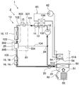
- the heat pump cycle device 2 of the present disclosure is applied to a vehicle air conditioner 1.
- vehicle air conditioner 1 includes a heat pump cycle device 2, an indoor air conditioning unit 50, and a control device 100.
- the heat pump cycle device 2 includes a heat pump circuit 10.
- the vehicle air conditioner 1 is mounted on an internal combustion engine (not shown) and a hybrid vehicle or the like that obtains a driving force for traveling the vehicle from a traveling electric motor.
- Hybrid vehicles and electric vehicles have less waste heat in the vehicle than in vehicles in which the driving force for traveling the vehicle can be obtained only by the internal combustion engine, and it is difficult to secure a heat source for heating the vehicle interior.
- the vehicle air conditioner 1 of this embodiment is configured to heat the vehicle interior by the indoor air conditioning unit 50 with the high-temperature and high-pressure refrigerant discharged from the compressor 12 of the heat pump circuit 10 as a heat source. .
- the heat pump circuit 10 is a fluid circulation circuit in which a refrigerant as a predetermined fluid circulates.
- the heat pump circuit 10 constitutes a heat pump cycle. More specifically, the heat pump circuit 10 adopts an HFC refrigerant (for example, R134a) as the refrigerant, and constitutes a vapor compression subcritical refrigeration cycle in which the high-pressure refrigerant pressure does not exceed the critical pressure of the refrigerant.
- an HFO refrigerant for example, R1234yf
- carbon dioxide or the like may be employed as the refrigerant.
- the heat pump circuit 10 switches between a refrigerant circuit of a cooling mode for cooling the air by cooling air blown into the vehicle compartment and a refrigerant circuit of a heating mode for heating the air by heating air blown into the vehicle room. It is configured to be possible.
- the blowing air into the vehicle compartment is the fluid to be temperature controlled.
- the cooling mode corresponds to the cooling mode for cooling the temperature control target fluid
- the heating mode corresponds to the heating mode for heating the temperature control target fluid.
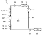
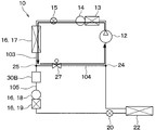
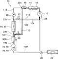
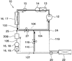
- the heat pump circuit 10 includes a compressor 12, a water-refrigerant heat exchanger 13, a heating storage reservoir 14, an outdoor heat exchanger 16, a cooling expansion valve 20, an evaporator 22, an integrated valve device 30, and the like.
- the compressor 12 is disposed inside the bonnet.
- the compressor 12 compresses and discharges the sucked refrigerant.
- the compressor 12 of the present embodiment is configured of an electric compressor driven by an electric motor (not shown).
- the compressor 12 can change the discharge capacity of the refrigerant according to the number of rotations of the electric motor.
- the operation of the compressor 12 is controlled by a control signal output from the control device 100.
- the water-refrigerant heat exchanger 13 includes a first heat exchange unit 132 through which the high pressure refrigerant discharged from the compressor 12 flows, and a second heat exchange unit 134 through which the antifreeze liquid flows.
- the water-refrigerant heat exchanger 13 is a radiator that radiates the refrigerant flowing through the first heat exchange unit 132 by heat exchange with the antifreeze liquid flowing through the second heat exchange unit 134.
- the antifreeze liquid flowing through the second heat exchange unit 134 is heated by the refrigerant flowing through the first heat exchange unit 132.
- the second heat exchange unit 134 is provided in the antifreeze fluid circulation circuit 60 through which the antifreeze fluid flows.
- the antifreeze fluid circulation circuit 60 is provided with a circulation pump 62 for circulating the antifreeze fluid, and a heater core 64 for radiating the antifreeze fluid.
- the operation of the circulation pump 62 is controlled by a control signal from the control device 100.
- the heater core 64 is disposed in the hot air passage 512 formed in the air conditioning case 51 of the indoor air conditioning unit 50.
- the heater core 64 is a radiator that dissipates the antifreeze liquid flowing inside by heat exchange with the blowing air passing through the hot air passage 512.
- the blast air passing through the hot air passage 512 is heated by the antifreeze liquid flowing through the heater core 64.
- the water-refrigerant heat exchanger 13 of the present embodiment functions as a radiator that indirectly radiates the high pressure refrigerant discharged from the compressor 12 to the blast air through the antifreeze liquid and the heater core 64.
- the heating reservoir 14 separates the refrigerant flowing out of the water-refrigerant heat exchanger 13 into liquid refrigerant and gas refrigerant.
- the heating reservoir 14 temporarily stores part of the refrigerant flowing out of the first heat exchange unit 132.
- the integrated valve device 30 is one valve device in which the heating expansion valve 15 and the three-way valve 26 are integrated.
- the integrated valve device 30 is configured as a combined control valve in which the heating expansion valve 15 and the three-way valve 26 operate in conjunction with each other.
- the integrated valve device 30 is controlled in its operation by a control signal from the control device 100.
- the integrated valve device 30 has a body portion 32, a heating expansion valve 15, and a three-way valve 26.
- a first inlet passage 301 and a second inlet passage 302 through which the refrigerant flows, and a first outlet passage 303 through which the refrigerant flows out, a second outlet passage 304 and a third outlet passage And 305 are formed.
- the first inlet passage 301 is an inlet passage of the heating expansion valve 15.
- the first outlet passage 303 is an outlet passage of the heating expansion valve 15.
- the second inlet passage 302 is an inlet passage of the three-way valve 26.
- the second outlet passage 304 and the third outlet passage 305 are outlet passages of the three-way valve 26.
- the first inlet passage 301 is connected to the flow passage 101 through which the refrigerant flowing out of the water-refrigerant heat exchanger 13 flows.
- the first outlet passage 303 is in communication with the flow passage 102 which guides the refrigerant to the core portion 17. Therefore, the first inlet passage 301 and the first outlet passage 303 are passages for pressure reducing devices which lead the refrigerant flowing out of the water-refrigerant heat exchanger 13 to the core portion 17.
- the second inlet passage 302 is continuous with the flow passage 103 through which the refrigerant flowing out of the core portion 17 flows. Therefore, the second inlet passage 302 is an introduction passage into which the refrigerant flowing out of the core portion 17 is introduced.
- the second outlet passage 304 is in communication with the heating passage 104 which guides the refrigerant to the suction side of the compressor 12 by bypassing the liquid receiver 18, the supercooling unit 19, the cooling expansion valve 20 and the evaporator 22.
- the third outlet passage 305 is connected to a cooling flow passage 105 for guiding the refrigerant to the suction side of the compressor 12 via the liquid receiver 18, the supercooling unit 19, the cooling expansion valve 20, and the evaporator 22.
- the heating flow path 104 corresponds to a heating side flow path for guiding the refrigerant flowing out of the heat exchanger in the heating mode to the compressor, bypassing the second pressure reducer and the evaporator.
- the cooling channel 105 corresponds to the cooling side channel that leads the refrigerant flowing out of the heat exchanger in the cooling mode to the compressor via the second pressure reducer and the evaporator. Therefore, the second outlet passage 304 is a heating side discharge passage for leading the refrigerant to the heating side flow passage.
- the third outlet passage 305 is a cooling side discharge passage for leading the refrigerant to the cooling side flow passage.
- the heating expansion valve 15 is a flow control valve that adjusts the flow rate of the refrigerant flowing from the first inlet passage 301 to the first outlet passage 303.
- the heating expansion valve 15 decompresses and expands the refrigerant flowing out of the heating liquid storage device 14 in the heating mode.
- the three-way valve 26 selectively switches between the heating channel 104 and the cooling channel 105.
- the three-way valve 26 is a flow path switching valve that switches the flow path of the refrigerant in the heat pump circuit 10.
- the outdoor heat exchanger 16 is a heat exchanger disposed outside the vehicle so as to be exposed to the air outside the vehicle (that is, outside air).
- the outdoor heat exchanger 16 is configured to include a core portion 17, a liquid receiver 18 and a supercooling portion 19.
- the core portion 17 is a heat exchanger that exchanges heat with the outside air as a heat medium other than the refrigerant.
- the core portion 17 functions as a heat sink absorbing heat from the outside air or a radiator discharging heat to the outside air according to the temperature of the refrigerant and the outside air temperature.
- the core portion 17 functions as a condenser that condenses the refrigerant by heat radiation to the outside air in the cooling mode.
- the core portion 17 functions as an evaporator that evaporates the refrigerant by heat absorption from the outside air in the heating mode.
- the liquid receiver 18 separates the refrigerant flowing out of the core portion 17 into a liquid refrigerant and a gas refrigerant.
- the receiver 18 temporarily stores part of the separated liquid refrigerant as surplus refrigerant in the cycle.
- the supercooling unit 19 is a heat exchanger that cools the liquid refrigerant flowing out of the liquid receiver 18 by exchanging heat with the outside air in the cooling mode.
- the cooling expansion valve 20 decompresses and expands the refrigerant flowing out of the outdoor heat exchanger 16 in the cooling mode.
- the cooling expansion valve 20 of the present embodiment is a temperature type that reduces and expands the refrigerant flowing into the evaporator 22 by a mechanical mechanism so that the degree of superheat of the refrigerant on the refrigerant outlet side of the evaporator 22 becomes a predetermined range. It consists of an expansion valve.
- An evaporator 22 is connected to the refrigerant outlet side of the cooling expansion valve 20.
- the evaporator 22 is disposed on the air flow upstream side of the heater core 64 in the air conditioning case 51 of the indoor air conditioning unit 50.
- the evaporator 22 is a cooling heat exchanger that evaporates the low pressure refrigerant decompressed by the cooling expansion valve 20 by heat exchange with the blowing air, and cools the blowing air.
- the refrigerant outlet side of the evaporator 22 is connected to the refrigerant suction side of the compressor 12.
- the refrigerant flow downstream of the evaporator 22 and the refrigerant flow downstream of the second outlet passage 304 of the integrated valve device 30 are provided between the evaporator 22 and the compressor 12.
- a merging portion 24 for merging is provided.
- the indoor air conditioning unit 50 is disposed inside the instrument panel (i.e., the instrument panel) at the front of the vehicle interior.
- the indoor air conditioning unit 50 has an air conditioning case 51 forming an outer shell and forming an air passage of the blowing air blown into the vehicle compartment inside.
- An internal / external air switching device 52 is provided on the most upstream side of the air flow of the air conditioning case 51.
- the internal / external air switching device 52 switches / introduces the air inside the vehicle (ie, the inside air) and the outside air.
- a blower 53 for directing the air introduced through the inside / outside air switching device 52 toward the vehicle interior and arranging the air is disposed.
- the blower 53 is configured by an electric blower.
- the rotation speed of the blower 53 is controlled by a control signal output from the control device 100 described later.
- An evaporator 22 and a heater core 64 are disposed downstream of the air flow of the blower 53.
- the evaporator 22 and the heater core 64 are disposed in the order of the evaporator 22 and the heater core 64 with respect to the flow of the blowing air.
- a warm air passage 512 in which the heater core 64 is disposed and a bypass passage 514 for flowing air around the warm air passage 512 are set downstream of the air flow of the evaporator 22. ing.
- an air mix door 54 for adjusting the air volume of the air flowing into the hot air passage 512 and the air volume of the air flowing into the bypass passage 514 is disposed.
- the operation of the air mix door 54 is controlled by a control signal output from the control device 100 described later.
- the air whose temperature has been adjusted by the evaporator 22 and the heater core 64 is blown out into the vehicle compartment through an opening (not shown).
- the control device 100 which is an electrical control unit of the vehicle air conditioner 1 will be described.
- the control device 100 is configured of a known microcomputer including a CPU, a ROM, a RAM, and the like, and peripheral circuits thereof.
- the storage unit of the control device 100 is configured of a non-transitional substantial storage medium.
- the control device 100 performs various calculations and processing based on a control program stored in a ROM or the like, and the compressor 12 connected to the output side, the integrated valve device 30, the circulation pump 62, the inside / outside air switching device 52, the blower 53 , Controls the operation of each control device such as the air mix door 54 and the like.
- control unit 100 is integrally configured with a control unit that controls the operation of each control device connected to the output side.
- a configuration for example, hardware or software
- a drive control unit that drives the integrated valve device 30.
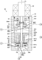
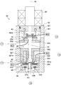
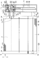
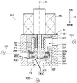
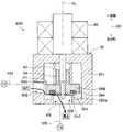
- the integrated valve device 30 includes a body portion 32, a rod 34, a first valve body 36, a second valve body 38, a first biasing spring 40, a second biasing spring 42 and an actuator 46.
- Arrow AD shown in FIG. 3 is a direction extending along the axial center CL of the rod 34 of the integrated valve device 30 (ie, the axial direction of the rod 34).
- the axial center CL of the rod 34 in the present embodiment extends in the vertical direction.
- the axial direction AD of the rod 34 is in the same direction as the vertical direction.
- One side of the axial direction AD corresponds to the upper side.
- the other side of the axial direction AD corresponds to the lower side.
- the body portion 32 is made of a metal material excellent in heat resistance and pressure resistance.
- the body portion 32 may be made of a resin material excellent in heat resistance and pressure resistance.
- An internal space 33 forming a refrigerant passage is formed inside the body portion 32.
- the body portion 32 has a cylindrical portion 321, a partition portion 322, a first valve seat forming portion 323, a second valve seat forming portion 324, and a third valve seat forming portion 325.
- the cylindrical portion 321 is a cylindrical member that constitutes the outer shape of the body portion 32. Inside the cylindrical portion 321, a partition 322, a first valve seat forming portion 323, a second valve seat forming portion 324, and a third valve seat forming portion 325 are provided.
- the partitioning portion 322 partitions the internal space 33 into an upper space 33a and a lower space 33b.
- the upper space 33 a is a space above the partition 322.
- the lower space 33 b is a space below the partition 322.
- the partition portion 322 is configured of a member separate from the cylindrical portion 321.
- the partition portion 322 is fixed to the cylindrical portion 321 by press fitting or the like.
- a first valve seat forming portion 323, a first valve body 36 and a first biasing spring 40 are provided in the upper side space 33a.
- the first valve seat forming portion 323, the first valve body 36 and the first urging spring 40 constitute a heating expansion valve 15.
- the first valve seat forming portion 323 corresponds to a flow valve seat forming portion.
- the first valve body 36 corresponds to the flow rate adjusting valve body.
- the first biasing spring 40 corresponds to a flow biasing member.
- the first valve seat forming portion 323 forms a first valve seat 323a.
- the first valve seat 323 a is a main valve body valve seat to which the main valve body 362 of the first valve body 36 contacts and separates.
- a first inlet passage 301 is formed on the upper side space 33 a above the first valve seat forming portion 323.
- a first outlet passage 303 is formed on the lower side of the first valve seat forming portion 323 in the upper side space 33a. Therefore, the upper side space 33a corresponds to the space on the first outlet passage side including the first outlet passage 303 in the inside of the body portion 32 partitioned by the partition portion 322.
- a passage communication hole 306 for communicating the first inlet passage 301 and the first outlet passage 303 is formed in the first valve seat forming portion 323.
- the first valve seat forming portion 323 is a member separate from the cylindrical portion 321.
- the first valve seat forming portion 323 is fixed to the cylindrical portion 321 by press fitting or the like.
- the first valve body 36 is disposed above the first valve seat forming portion 323.
- the first valve body 36 has a main valve body 362 and an auxiliary valve body 364.
- the main valve body 362 contacts and separates the first valve seat 323 a.
- the main valve body 362 is not fixed to the rod 34.
- the main valve body 362 is formed with a first insertion hole 362 a through which the rod 34 is inserted.
- the diameter of the first insertion hole 362a is larger than the outer diameter of the rod 34 so that a gap passage 307 through which the refrigerant flows is formed between the inner wall surface of the first insertion hole 362a and the rod 34.
- the first insertion hole 362 a formed in the main valve body 362 has a larger hole diameter than the second insertion hole 38 a formed in the second valve body 38.
- the sub valve body 364 is a valve body that adjusts the opening area of the gap passage 307 in a state where the main valve body 362 abuts on the first valve seat 323 a.
- the auxiliary valve body 364 is fixed to the rod 34. For this reason, the sub valve body 364 is configured to be movable integrally with the rod 34.
- the auxiliary valve body 364 is formed of a valve body whose outer diameter is smaller than that of the main valve body 362.
- the auxiliary valve body 364 is disposed on the upper side of the main valve body 362.
- the auxiliary valve body 364 also functions as a pressing portion that pushes the main valve body 362 upward, that is, the side where the main valve body 362 is separated from the first valve seat 323a.
- the sub valve contact portion 362b that contacts the sub valve body 364 Is provided.
- the sub valve contact portion 362 b is connected to the main valve body 362.
- the sub valve contact portion 362 b is a cylindrical member having a bottom on one side. An opening is formed in the side wall of the tubular member.
- the first biasing spring 40 is disposed on the upper side of the main valve body 362.
- the first biasing spring 40 is a biasing member that biases the main valve body 362 downward, that is, the main valve body 362 is directed to the first valve seat 323a.
- the first biasing spring 40 is a coil spring.
- the rod 34 moves from the lower side to the upper side, the sub valve body 364 abuts against the sub valve contact portion 362 b, and the sub valve body 364 pushes the sub valve contact portion 362 b upward, whereby the rod 34 moves upward.
- the main valve body 362 is energized. As a result, the main valve body 362 is separated from the first valve seat 323a.
- the first inlet passage 301 and the first outlet passage 303 communicate with each other through the gap 308 between the main valve body 362 and the first valve seat 323 a and the passage communication hole 306. As a result, the flow rate adjustment passage between the first inlet passage 301 and the first outlet passage 303 is opened.
- the open state is a state in which the refrigerant flows from the first inlet passage 301 to the first outlet passage 303 without reducing the pressure of the refrigerant almost at all.
- the opening area of the flow rate adjustment passage is set to a predetermined size.
- the gap 308 between the main valve body 362 and the first valve seat 323a and the passage communication hole 306 mainly constitute a flow rate adjustment passage.
- the rod 34 moves from the upper side to the lower side and the sub valve 364 separates from the sub valve contact portion 362 b, the rod 34 does not bias the main valve 362.
- the first biasing spring 40 biases the main valve body 362 downward.
- the main valve body 362 abuts on the first valve seat 323a, and the gap 308 between the main valve body 362 and the first valve seat 323a disappears.
- the first inlet passage 301 and the first outlet passage 303 communicate with each other through the passage communication hole 306 and the clearance passage 307. As a result, the flow rate adjustment passage between the first inlet passage 301 and the first outlet passage 303 is squeezed.
- the clearance passage 307 and the passage communication hole 306 constitute a flow rate adjustment passage.
- the opening area of the flow rate adjustment passage is smaller than that in the open state. That is, the throttling state is a state in which the flow of the refrigerant flowing from the first inlet passage 301 to the first outlet passage 303 is narrowed more than in the open state.
- the auxiliary valve body 364 reduces the opening area of the gap passage 307 as the rod 34 moves from the upper side to the lower side.
- the first valve body 36 when the rod 34 moves upward and the main valve body 362 separates from the first valve seat 323a, the first valve body 36 is in the open state. In addition, when the rod 34 moves downward and the main valve body 362 abuts on the first valve seat forming portion 323, the first valve body 36 is in a squeezed state in which the pressure reducing action of the refrigerant is exhibited. That is, the first valve body 36 is configured to be able to switch between the open state and the throttling state.
- the first valve body 36 can adjust the opening area of the gap passage 307 to a desired size by displacing the sub valve body 364 in the squeezed state. That is, in the throttling state, the first valve body 36 can reduce the pressure of the refrigerant flowing out of the first outlet passage 303 to a desired pressure.
- the first valve body 36 is configured to be able to adjust the flow rate of the refrigerant when in the throttling state.
- the sub valve body 364 is displaced to finely adjust the opening degree of the gap passage 307.
- the driving force required when moving the rod 34 can be reduced.
- a second valve seat forming portion 324, a third valve seat forming portion 325, a second valve body 38 and a second biasing spring 42 are provided in the lower side space 33b.
- the second valve seat forming portion 324, the third valve seat forming portion 325, the second valve body 38 and the second biasing spring 42 constitute a three-way valve 26.
- the second valve body 38 corresponds to the flow path switching valve body.
- the second valve seat forming portion 324 corresponds to the switching valve seat forming portion disposed on the partition side of the flow path switching valve body.
- the second biasing spring 42 corresponds to the switching biasing member.
- a second outlet passage 304 is formed on the lower side space 33 b above the second valve seat forming portion 324. Accordingly, the lower side space 33 b corresponds to the space on the second outlet passage side including the second outlet passage 304 in the inside of the body portion 32 partitioned by the partition portion 322.
- a second inlet passage 302 is formed between the second valve seat forming portion 324 and the third valve seat forming portion 325 in the lower side space 33 b.
- a passage communication hole communicating with the second inlet passage 302 is formed in the third valve seat forming portion 325.
- the passage communication hole constitutes a third outlet passage 305.
- the second valve seat forming portion 324 is disposed above the second valve body 38.
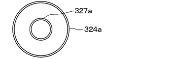
- the second valve seat forming portion 324 forms a second valve seat 324a.
- the second valve seat 324 a contacts or separates the upper side of the second valve body 38, that is, the side of the partition portion 322 of the second valve body 38.
- the second valve seat 324 a corresponds to a switching valve seat in the flow path switching valve body which is brought into contact with or separated from the partition portion side.
- the second valve seat forming portion 324 is connected to the partition portion 322 via the connecting portion 326.
- the second valve seat forming portion 324 is configured as a member integral with the partition portion 322.
- An integral member is a seamless and continuous member.
- the third valve seat forming portion 325 is disposed below the second valve body 38.
- the third valve seat forming portion 325 forms a third valve seat 325 a.
- the third valve seat 325 a is in contact with or separated from the lower side of the second valve body 38, that is, the side of the second valve body 38 that is apart from the partition portion 322.
- the third valve seat forming portion 325 is configured as a member integral with the cylindrical portion 321.
- the second valve body 38 is disposed between the second valve seat forming portion 324 and the third valve seat forming portion 325 in the axial direction AD.
- packings 382 and 384 are provided on a portion of the second valve seat forming portion 324 in contact with the valve seat 324a and a portion of the third valve seat forming portion 325 in contact with the valve seat 325a.
- the second valve body 38 is not fixed to the rod 34.
- a second insertion hole 38 a through which the rod 34 is inserted is formed in the second valve body 38.
- the second insertion hole 38a has a hole diameter slightly larger than the outer diameter of the rod 34 such that a minute gap passage through which the refrigerant hardly flows is formed between the rod 34 and the inner wall surface of the second insertion hole 38a. It has become.
- the second biasing spring 42 is disposed above the second valve body 38.
- the second biasing spring 42 is a biasing member that biases the second valve body 38 downward, that is, in a direction in which the second valve body 38 closes the third outlet passage 305.
- the second biasing spring 42 is a coil spring. The biasing of the second biasing spring 42 causes the second valve body 38 to abut on the third valve seat 325 a. As a result, the second inlet passage 302 communicates with the second outlet passage 304, and the third outlet passage 305 is closed in the first communication state.
- the second valve body 38 is pressed upward by the pressing portion 342 provided on the rod 34 against the biasing of the second biasing spring 42. At this time, the second valve body 38 is biased in the upward direction, that is, in the direction in which the second outlet passage 304 is closed.
- the second valve body 38 abuts on the second valve seat forming portion 325. As a result, the second inlet passage 302 communicates with the third outlet passage 305 while the second outlet passage 304 is closed.
- the second valve body 38 When the second valve body 38 is released from the contact state with the pressing portion 342, the second valve body 38 moves downward by the biasing force of the second biasing spring 42. Thus, the second valve body 38 is in the first communication state.
- the rod 34 is a shaft member that interlocks the first valve body 36 and the second valve body 38.
- the rod 34 displaces the first valve body 36 and the second valve body 38 by moving along the axial center CL.
- the rod 34 is formed of a single rod-like member extending along the axis CL.
- the main valve body 362 and the second valve body 38 are attached to the rod 34.
- the rod 34 is integrally provided with a pressing portion 342 for pressing the sub valve 364 and the second valve 38.
- the upper end of the rod 34 is connected to the actuator 46, and is moved in the axial direction AD by the driving force output from the actuator 46.
- the integrated valve device 30 includes a sealing member 44 that seals the gap between the inner wall surface of the third insertion hole 322 a and the rod 34 in a state where the rod 34 can slide.
- the sealing member 44 is a ring-shaped elastic member.
- the sealing member 44 is covered by a cover portion 322 b provided on the upper side of the partition portion 322. The sealing member 44 can prevent the refrigerant flowing in the first outlet passage 303 from flowing into the second outlet passage 304 from the gap between the inner wall surface of the third insertion hole 322 a and the rod 34.
- the partition part 322 has a cylindrical part 327 extending toward the three-way valve 26 from the peripheral part of the third insertion hole 322 a.
- the rod 34 is inserted into the inside of the cylindrical portion 327.
- the cylindrical portion 327 supports the second biasing spring 42.
- the actuator 46 is a drive unit that outputs a driving force that moves the rod 34 in the axial direction AD.
- the actuator 46 according to the present embodiment is formed of a linear actuator which converts rotational motion into linear motion (i.e., sliding motion) and outputs it.
- the actuator 46 of the present embodiment includes an electric motor, a power conversion mechanism, and the like that generate a rotational drive force by energization.
- the electric motor is configured of a stepping motor capable of controlling the rotation angle according to the input pulse signal.
- the power conversion mechanism is a mechanism that converts the rotational motion of the output shaft of the electric motor into a linear motion to move the rod 34 in the axial direction AD.
- FIG. 4 is a characteristic diagram showing the relationship between the opening area of each of the first outlet passage 303, the second outlet passage 304, and the third outlet passage 305 in the integrated valve device 30, and the position of the rod 34.
- changes in the opening area of the first outlet passage 303 are indicated by a solid line
- changes in the opening area of the second outlet passage 304 are indicated by a broken line
- changes in the opening area of the third outlet passage 305 are indicated by a dashed dotted line.
- the opening area of the first outlet passage 303 is a passage cross-sectional area of the flow rate adjustment passage adjusted by the first valve body 36.
- each of the second outlet passage 304 and the third outlet passage 305 is the passage cross-sectional area of each of the second outlet passage 304 and the third outlet passage 305 adjusted by the second valve body 38.
- the opening area of each of the first outlet passage 303, the second outlet passage 304, and the third outlet passage 305 is a passage cross-sectional area effective for the refrigerant to flow.
- the integrated valve device 30 can adjust the opening area of each of the first outlet passage 303, the second outlet passage 304, and the third outlet passage 305 by changing the position of the rod 34. ing.
- the lowest position of the rod 34 corresponds to the state of the integrated valve device 30 shown in FIG.
- the position of the rod 34 in the heating position corresponds to the state of the integrated valve device 30 shown in FIG.
- the position of the rod 34 at the refrigerant position corresponds to the state of the integrated valve device 30 shown in FIG.
- the second valve body 38 when the position of the rod 34 is at the lowermost position, as shown in FIG. 3, the pressing portion 342 of the rod 34 is separated from the second valve body 38. For this reason, the second biasing spring 42 biases the second valve body 38. The rod 34 does not bias the second valve body 38. As a result, the second valve body 38 separates from the second valve seat 324a, and the second valve body 38 abuts on the third valve seat 325a. As a result, the second outlet passage 304 is fully opened, and the third outlet passage 305 is fully closed. That is, as shown in FIG. 4, the opening area of the second outlet passage 304 is maximized, and the opening area of the third outlet passage 305 is zero. Thus, as shown in FIG. 3, the second valve body 38 is in the first communication state in which the third outlet passage 305 is closed while the second inlet passage 302 is in communication with the second outlet passage 304.
- the auxiliary valve body 364 of the first valve body 36 is separated from the auxiliary valve contact portion 362b.
- the first biasing spring 40 biases the main valve body 362.
- the rod 34 does not bias the main valve body 362.
- the main valve body 362 abuts on the first valve seat 323a.
- the auxiliary valve body 364 abuts on the main valve body 362, and the gap passage 307 is closed.
- the first outlet passage 303 is fully closed. That is, as shown in FIG. 4, the opening area of the first outlet passage 303 is zero. At this time, since the first outlet passage 303 is fully closed, the circulation of the refrigerant in the heat pump circuit 10 is stopped.
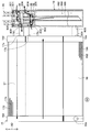
- the rod 34 moves upward from the lowermost position, and the position of the rod 34 becomes the heating position. At this time, as shown in FIG. 5, the pressing portion 342 of the rod 34 remains separated from the second valve body 38. Therefore, as in the lowermost position, the second valve body 38 is in the first communication state.
- the auxiliary valve body 364 of the first valve body 36 separates from the main valve body 362. Therefore, the first inlet passage 301 and the first outlet passage 303 communicate with each other through the gap passage 307 and the passage communication hole 306. Thus, the refrigerant flowing from the first inlet passage 301 to the first outlet passage 303 is depressurized to a desired pressure.
- the second biasing spring 42 biases the second valve body 38, and the rod 34 does not bias the second valve body 38, whereby the second valve body 38 maintains the first communication state. For this reason, when in the first communication state, the position of the rod 34 can be changed to finely adjust the position of the sub valve 364. Thereby, the opening area of the first outlet passage 303 can be changed in the variable stop use area in FIG. 4.
- the pressing portion 342 when the position of the rod 34 is in the variable throttle use area, the pressing portion 342 is separated from the second valve body 38. For this reason, the second biasing spring 42 biases the second valve body 38 and the rod 34 does not bias the second valve body 38 so that the second valve body 38 maintains the first communication state. Can. Then, when the second valve body 38 is in the first communication state, the rod 34 biases the sub valve body 364 of the first valve body 36 so that the first valve body 36 adjusts the flow rate of the refrigerant. it can.
- the distance L2 in the axial direction AD between the pressing portion 342 and the second valve body 38 is the sub valve body It is equal to or longer than the distance L1 in the axial direction AD between 364 and the auxiliary valve contact portion 362b. For this reason, when the position of the rod 34 is within the variable throttling use range where the opening area of the first outlet passage 303 can be changed, the pressing portion 342 is in a state of being separated from the second valve body 38.
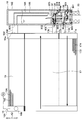
- the pressing portion 342 of the rod 34 abuts on the second valve body 38 as shown in FIG.
- the rod 34 biases the second valve body 38 upward against the bias of the second biasing spring 42.
- the second valve body 38 separates from the third valve seat 325a, and the second valve body 38 abuts on the second valve seat 324a.
- the second outlet passage 304 is fully closed, and the third outlet passage 305 is fully opened. That is, as shown in FIG. 4, the opening area of the second outlet passage 304 is zero, and the opening area of the third outlet passage 305 is maximum. Therefore, as shown in FIG. 6, the second valve body 38 is in the second communication state in which the second outlet passage 304 is closed while the second inlet passage 302 is in communication with the third outlet passage 305.
- the auxiliary valve body 364 of the first valve body 36 abuts on the auxiliary valve contact portion 362 b.
- the rod 34 biases the main valve body 362 upward.
- the main valve body 362 is separated from the first valve seat 323a. Therefore, the first inlet passage 301 and the first outlet passage 303 communicate with each other through the gap 308 between the main valve body 362 and the first valve seat 323a and the passage communication hole 306. Therefore, the refrigerant flowing from the first inlet passage 301 to the first outlet passage 303 flows into the core portion 17 of the outdoor heat exchanger 16 with almost no pressure reduction.
- the second valve body 38 can selectively switch between the first communication state and the second communication state by moving in the axial direction AD.
- the first valve body 36 moves in the axial direction AD to allow the refrigerant to flow from the first inlet passage 301 to the first outlet passage 303, and the first valve body 36 to flow the refrigerant from the first inlet passage 301 to the first outlet passage 303. It is possible to switch between the throttle state where the flow is narrowed rather than the open state.
- the first valve body 36 can adjust the flow rate of the refrigerant when in the throttling state. That is, the first valve body 36 can switch between the open state and the variable throttle state.
- the moving direction of the rod 34 for switching the first valve body 36 from the variable throttle state to the open state and the flow rate of the refrigerant when the first valve body 36 is in the variable throttle state The direction of movement of the rod 34 is the same upper side. That is, the direction in which the opening area of the first outlet passage 303 is increased is the same as the moving direction of the rod 34 toward one side in the axial direction AD.
- the control of the first valve body 36 is facilitated compared to the case where the direction of increasing the opening area of the first outlet passage 303 is not the same as the moving direction of the rod 34 toward one side in the axial direction AD. ing.
- the moving direction of the rod 34 for switching the first valve body 36 from the variable throttle state to the open state and the flow rate of the refrigerant when the first valve body 36 is in the variable throttle state It can be considered that the movement direction of the rod 34 of is opposite. In this case, if the opening area of the first outlet passage 303 is made too small while the first valve body 36 is in the variable throttle state, the first valve body 36 will be in the open state.
- the opening state of the first valve body 36 is avoided when the opening area of the first outlet passage 303 is made too small. it can.
- the vehicle air conditioner 1 of the present embodiment can switch the operation mode to the cooling mode and the heating mode by the control of each control device by the control device 100.
- the operation in the cooling mode and the heating mode of the vehicle air conditioner 1 will be described.
- the control device 100 controls the air mix door 54 at a position where the bypass passage 514 is opened as shown in FIG. 7. As a result, in the indoor air conditioning unit 50 in the cooling mode, the entire flow rate of the blown air after passing through the evaporator 22 passes through the bypass passage 514. The control device 100 stops the circulation pump 62 so that the heat exchange between the refrigerant and the antifreeze liquid is not performed in the water-refrigerant heat exchanger 13.
- control device 100 controls the actuator 46 so that the position of the rod 34 becomes the cooling position shown in FIG.
- the heat pump circuit 10 becomes a refrigerant circuit in the cooling mode.
- the high-pressure refrigerant discharged from the compressor 12 flows into the water-refrigerant heat exchanger 13.
- the circulation pump 62 is stopped, in the water-refrigerant heat exchanger 13, the high pressure refrigerant flows into the integrated valve device 30 with almost no heat exchange with the antifreeze liquid.
- the heating expansion valve 15 in the cooling mode, the heating expansion valve 15 is in the open state. For this reason, the high-pressure refrigerant flowing into the first inlet passage 301 of the integrated valve device 30 flows out of the first outlet passage 303 with almost no pressure reduction.
- the high-pressure refrigerant flowing out of the first outlet passage 303 flows into the core portion 17 of the outdoor heat exchanger 16. Then, the high pressure refrigerant flowing into the core portion 17 dissipates heat to the outside air, and then flows into the second inlet passage 302 of the integrated valve device 30.
- the three-way valve 26 is in the second communication state. Therefore, the high pressure refrigerant flowing into the second inlet passage 302 flows into the receiver 18 through the third outlet passage 305.
- the high pressure refrigerant flowing into the liquid receiver 18 is separated into a gas phase refrigerant and a liquid phase refrigerant.
- the liquid refrigerant stored in the receiver 18 flows into the subcooling unit 19.
- the high pressure refrigerant flowing into the supercooling unit 19 dissipates heat to the outside air, and then flows into the cooling expansion valve 20 and is decompressed until it becomes a low pressure refrigerant.
- the refrigerant which has been reduced in pressure by the cooling expansion valve 20, flows into the evaporator 22, absorbs heat from the air blown into the vehicle compartment and evaporates, and then is drawn into the compressor 12 again.
- the blown air is blown into the vehicle compartment without being heated by the heater core 64. Thereby, cooling of the vehicle compartment is realized.
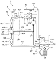
- control device 100 controls air mix door 54 to a position closing bypass passage 514 as shown in FIG. 8.
- the indoor air conditioning unit 50 in the heating mode is configured such that the total flow rate of the blown air after passing through the evaporator 22 passes through the hot air passage 512.
- the control device 100 operates the circulation pump 62 so that the heat exchange between the refrigerant and the antifreeze liquid is performed by the water-refrigerant heat exchanger 13.
- control device 100 controls the actuator 46 so that the position of the rod 34 becomes the heating position shown in FIG. 5.
- the heat pump circuit 10 becomes a refrigerant circuit in the heating mode.
- the high pressure refrigerant discharged from the compressor 12 flows into the first heat exchange portion 132 of the water-refrigerant heat exchanger 13, and the heat possessed by the high pressure refrigerant flows through the antifreeze liquid and the heater core 64. Heat is dissipated to the blast air.
- the high pressure refrigerant radiated by the water-refrigerant heat exchanger 13 is separated into a gas and a liquid by the heating reservoir 14. Then, the liquid refrigerant separated by the heating storage liquid 14 flows into the integrated valve device 30.
- the heating expansion valve 15 is in the variable throttle state. Therefore, the high pressure refrigerant flowing into the first inlet passage 301 of the integrated valve device 30 is depressurized to be a low pressure refrigerant, and then flows out from the first outlet passage 303.
- the control device 100 sets the opening area of the first outlet passage 303 (that is, the control device 100 sets the flow rate adjustment passage) so that the degree of superheat of the refrigerant suction side of the compressor 12 becomes a predetermined range.
- the opening area of the gap passage 307 to be configured is adjusted.
- the refrigerant flowing out of the first outlet passage 303 flows into the core portion 17 of the outdoor heat exchanger 16.
- the refrigerant flowing into the core portion 17 absorbs heat from the outside air and evaporates.
- the gas refrigerant evaporated in the core portion 17 flows into the second inlet passage 302 of the integrated valve device 30.
- the three-way valve 26 is in the first communication state. Therefore, the low-pressure refrigerant flowing into the second inlet passage 302 flows out of the second outlet passage 305 and flows through the heating passage 104.
- the gas refrigerant that has flowed out of the integrated valve device 30 flows to the refrigerant suction side of the compressor 12 via the heating flow path 104 and is compressed again by the compressor 12.
- the heat of the high-pressure refrigerant in the heat pump circuit 10 indirectly heats the blowing air. Then, the blowing air heated by the indoor air conditioning unit 50 is blown out into the vehicle compartment. Thereby, heating of the vehicle interior is realized.
- the refrigerant pressure P1 of the second inlet passage 302 of the integrated valve device 30 is lower than the refrigerant pressure P2 of the third outlet passage 305, and both pressures
- the pressure difference causes the second valve body 38 to open the third outlet passage 305.
- the second valve body 38 blocks the third outlet passage 305 when the pressure difference is smaller than a predetermined value.
- the biasing force of the second biasing spring 42 is set such that the second valve body 38 opens the third outlet passage 305 when the pressure difference is larger than a predetermined value.
- the predetermined value is a pressure value greater than zero.
- the rod 34 has a stepped portion 344.
- the stepped portion 344 is located above the second valve body 38.
- the step portion 344 functions as a stopper for stopping the movement of the second valve body 38 when the second valve body 38 moves upward while the rod 34 is in the movement stop state.
- the position of the rod 34 is set to the heating position. For this reason, as shown in FIG. 5, the second valve body 38 blocks the third outlet passage 305.
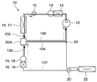
- the refrigerant pressure in the low pressure passage 106 in FIG. 8 decreases immediately after the start of the heating mode.
- the refrigerant pressure of the pre-evaporator flow path 107 in FIG. 8 is maintained at a saturation pressure corresponding to the ambient temperature of the place where the pre-evaporator flow path 107 is disposed.
- the refrigerant pressure of the evaporator front flow path 107 is higher than the saturation pressure corresponding to the atmosphere temperature.
- the low pressure flow path 106 is a refrigerant flow path in which a low pressure refrigerant whose pressure is reduced by the heating expansion valve 15 and which is lower than the high pressure refrigerant discharged from the compressor 12 flows toward the compressor 12.
- the low pressure passage 106 is a refrigerant passage between the refrigerant outlet of the heating expansion valve 15 and the refrigerant suction port of the compressor 12 in the heating mode.
- the pre-evaporator flow path 107 has the second valve body 38 and the evaporator 22 when the second valve body 38 is in the position shown in FIG. 5 (that is, the position where the second valve body 38 blocks the third outlet passage 305). And a refrigerant passage between the
- the refrigerant pressure P1 of the second inlet passage 302 becomes lower than the refrigerant pressure P2 of the third outlet passage 305. Then, when the pressure difference between the two becomes larger than a predetermined value, as shown in FIG. 9, the second valve body 38 moves upward due to the pressure difference between the two. The second valve body 38 abuts on the stepped portion 344.
- the second valve body 38 opens the third outlet passage 305 while keeping the second outlet passage 304 open. That is, the second valve body 38 causes the evaporator front flow passage 107 in FIG. 10 to communicate with the low pressure flow passage 106 without passing through the evaporator 22.
- the liquid refrigerant stagnated in the evaporator front flow passage 107 flows from the third outlet passage 305 of the integrated valve device 30 to the second outlet passage 304 as shown in FIG.
- the refrigerant flowing out of the second outlet passage 304 is drawn into the compressor 12 via the heating flow passage 104.
- the gap between the second valve body 38 and the valve seat 325 a of the third valve seat forming portion 325 shown in FIG. 9 bypasses the evaporator 22 and transfers the evaporator front flow path 107 to the low pressure flow path 106. It becomes the communication part 310 to make it connect.
- the flow of the communication portion 310 is such that more refrigerant flows toward the communication portion 310 than the evaporator 22.
- the path resistance is set to be smaller than the flow path resistance of the evaporator 22.
- the size of the passage cross-sectional area of the communication portion 310 is set such that the flow passage resistance of the communication portion 310 becomes a desired flow passage resistance. That is, the gap dimension between the second valve body 38 and the valve seat 325 a of the third valve seat forming portion 325 is set.
- the refrigerant that has fallen to the second valve body 38 side in the evaporator front flow path 107 rather than the cooling expansion valve 20 is transferred to the compressor 12 via the cooling expansion valve 20 and the evaporator 22.
- the refrigerant can be recovered more quickly than in the case of flowing into the Therefore, the refrigerant shortage state of the heat pump circuit 10 in the heating mode can be avoided.
- the communication part is made such that most of the refrigerant in the flow path 107 in the front of the evaporator flows to the low pressure flow path 106 via only the communication part 310 of the evaporator 22 and the communication part 310.
- a flow path resistance of 310 was set.
- the flow path resistance of the communication portion 310 may be set such that the refrigerant in the evaporator front flow path 107 flows to the low pressure flow path 106 via both the evaporator 22 and the communication portion 310.
- the flow passage resistance of the communication portion 310 may be set to the same as the flow passage resistance of the evaporator 22.
- the temperature decrease of the evaporator 22 at the time of recovery of the refrigerant is suppressed, as compared with the case where the refrigerant of the evaporator front flow passage 107 flows to the low pressure flow passage 106 only via the evaporator 22. be able to. Therefore, it is possible to suppress the generation of frost and frozen odor of the evaporator 22.
- the heat pump circuit 10 may be in a state of refrigerant shortage at the start of the heating mode.
- the cooling expansion valve 20 At least a portion of the refrigerant stagnated in the portion on the second valve body 38 side of the cooling expansion valve 20 in the evaporator front flow path 107 is the cooling expansion valve 20.
- the evaporator 22 can be diverted to the compressor 12. Therefore, the refrigerant can be recovered more quickly than when the refrigerant is recovered by the compressor 12 only via the cooling expansion valve 20 and the evaporator 22. Therefore, the refrigerant shortage of the heat pump circuit 10 in the heating mode can be suppressed.
- the second valve body 38 closes the third outlet passage 305.
- the evaporator 22 is bypassed, and the evaporator front flow path 107 does not communicate with the low pressure flow path 106. That is, the flow path in which the front evaporator flow path 107 communicates with the low pressure flow path 106 is blocked without passing through the evaporator 22.
- the second valve body 38 bypasses the evaporator and pre-evaporator The flow path 107 is not in communication with the low pressure flow path 106.
- the pressure difference is smaller than a predetermined value, the case where there is no pressure difference is included.
- the three-way valve 26 of the integrated valve device 30 has a differential pressure valve function. That is, in the heating mode, the second valve body 38 of the three-way valve 26 maintains the heating channel 104 open, and the refrigerant pressure of the low pressure channel 106 is higher than the refrigerant pressure of the evaporator front channel 107.
- the cooling flow path 105 is opened by the pressure difference between the two when it is too low.
- the heating mode is activated, the evaporator front flow passage 107 communicates with the low pressure flow passage 106 without passing through the evaporator 22.
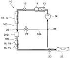
- the heat pump circuit 10 of this embodiment it is possible to change the heat pump circuit 10 of this embodiment as follows. That is, the three-way valve 26 of the integrated valve device 30 does not have the differential pressure valve function of this embodiment.
- the heat pump circuit 10 communicates the evaporator front channel 107 with the low pressure channel 106 without passing through the evaporator 22.
- a control valve for opening and closing the communication channel the control device 100 controls the control valve so as to open the communication flow path when the refrigerant pressure of the low pressure flow path 106 is lower than the refrigerant pressure of the evaporator front flow path 107. Also by this, the same effect as this embodiment can be obtained.
- the refrigerant in the flow path 107 before the evaporator is recovered at the start of the heating mode without adding the flow path switching unit for recovering the refrigerant to the heat pump circuit 10 be able to.
- the heat pump circuit 10 of the present embodiment uses an integrated valve device 30 in which a three-way valve having a differential pressure valve function and a heating expansion valve are integrated. Thereby, the number of components constituting the heat pump circuit 10 can be reduced, and the heat pump cycle device 2 can be simplified.
- the integrated valve device 30 of the present embodiment differs from the integrated valve device 30 of the first embodiment in the position of the end portion 327 a of the cylindrical portion 327 on the second valve body 38 side.
- the end 327 a of the cylindrical portion 327 abuts on the second valve body 38.
- the end 327 a of the cylindrical portion 327 is annular and located on the inner peripheral side of the second valve seat 324 a.
- the end portion 327a of the cylindrical portion 327 and the second valve seat 324a form a double annular valve seat that contacts the second valve body 38.
- the high pressure refrigerant flowing in the first outlet passage 303 is the inner wall surface of the insertion hole 322a. It is possible to prevent the flow into the second outlet passage 304 from the gap with the rod 34. Further, as shown in FIG. 13, in the heating mode, the second valve body 38 separates from both the second valve seat 324 a and the end 327 a of the cylindrical portion 327. As a result, the second valve body 38 is brought into the first communication state.
- the second valve body 38 opens the third outlet passage 305 in a state where the second outlet passage 304 is opened. For this reason, also in the present embodiment, the same effects as in the first embodiment can be obtained.
- the outdoor heat exchanger 16 is configured as a module in which the core portion 17, the liquid receiver 18 and the supercooling portion 19 are integrated. Furthermore, the body portion 32 of the integrated valve device 30 is accommodated inside the receiver 18.
- the other configuration of the heat pump circuit 10 is the same as that of the first embodiment.
- the outdoor heat exchanger 16 includes a core portion 17, a supercooling portion 19, a pair of header tanks 162 and 164, and a liquid receiver 18.
- the core portion 17 and the subcooling portion 19 are vertically stacked.
- the core portion 17 is disposed above the subcooling portion 19.
- the pair of header tanks 162 and 164 is disposed on both sides of the core portion 17 and the supercooling portion 19 in a direction intersecting the stacking direction of the core portion 17 and the subcooling portion 19.
- the core portion 17 includes a plurality of tubes 172 through which the refrigerant passes, and a plurality of fins 174 that promote heat exchange between the refrigerant and the outside air.
- Each of the plurality of tubes 172 is vertically stacked with an interval therebetween.
- the plurality of fins 174 are disposed between adjacent ones of the plurality of tubes 172.
- Each side of each of the plurality of tubes 172 is connected to each of the pair of header tanks 162, 164.
- the subcooling portion 19 has a plurality of tubes 192 and a plurality of fins 194. Each side of each of the plurality of tubes 192 is connected to each of the pair of header tanks 162, 164.
- the pair of header tanks 162 and 164 extend in the vertical direction.
- the part of the pair of header tanks 162 and 164 to which the plurality of tubes 172 of the core portion 17 are connected distributes and assembles the refrigerant flowing through the plurality of tubes 172 of the core portion 17.
- the part of the pair of header tanks 162 and 164 to which the plurality of tubes 192 of the subcooling unit 19 are connected distributes and assembles the refrigerant flowing through the plurality of tubes 192 of the subcooling unit 19.
- the receiver 18 is disposed adjacent to one header tank 162 of the pair of header tanks 162 and 164.
- the receiver 18 comprises a housing 182 which forms the outer shape of the receiver.
- the housing 182 extends in the extension direction of the pair of header tanks 162 and 164, that is, in the up and down direction.
- the housing 182 is cylindrical.
- a liquid reservoir 184 is formed inside the housing 182.
- the liquid reservoir 184 temporarily stores the liquid refrigerant.
- the liquid reservoir portion 184 is a space on the inner side of the housing 182 below the body portion 32 of the integrated valve device.
- the integrated valve device 30 of the present embodiment has the same structure as the integrated valve device 30 of the first embodiment.
- the body portion 32 of the integrated valve device 30 is disposed on the inner side of the housing 182 above the liquid reservoir portion 184.
- Connected to the third outlet passage 305 of the body portion 32 is a pipe 186 for sucking up the refrigerant present in the liquid reservoir portion 184 in the heating mode and leading it to the compressor 12.
- the tube 186 extends downward from the body portion 32. That is, the pipe 186 extends from the body 32 toward the lower end of the reservoir 184.
- a first opening 801, a second opening 802, a third opening 803, and a fourth opening 804 are formed in a portion of the housing 182 where the body portion 32 is accommodated.
- the first opening 801 communicates with the first inlet passage 301 of the body portion 32.
- the second opening 802 communicates with the second inlet passage 302 of the body portion 32.
- the third opening 803 communicates with the first outlet passage 303 of the body portion 32.
- the fourth opening 804 communicates with the second outlet passage 304 of the body portion 32.
- the refrigerant inlet 17 a of the core portion 17 provided in one header tank 162 is connected to the third opening 803 of the housing 182 via the connection pipe 176.
- the refrigerant outlet 17 b of the core portion 17 provided in one header tank 162 is connected to the second opening 802 of the housing 182 via the connection pipe 178.
- a fifth opening 805 is formed in a portion of the housing 182 where the liquid reservoir 184 is formed.
- the fifth opening 805 is an opening for communicating the liquid reservoir 184 and the supercooling unit 19 with each other.
- the refrigerant inlet 19 a of the subcooling unit 19 provided in one header tank 162 is connected to the fifth opening 805 via the connection pipe 196.
- the refrigerant outlet 19 b provided in one header tank 162 is connected to the refrigerant inlet of the cooling expansion valve 20.
- the outdoor heat exchanger 16 and the integrated valve device 30 are configured as a module in which both are integrated. Therefore, the number of components constituting the heat pump circuit 10 can be reduced.
- the heat pump circuit 10 can be simplified.
- the high-pressure refrigerant that has flowed into the first inlet passage 301 of the integrated valve device 30 passes from the first outlet passage 303 via the connection pipe 176 to the refrigerant inlet 17 a of the core portion 17.
- Flow into The high-pressure refrigerant flowing out of the refrigerant outlet 19 b of the core portion 17 flows into the receiver 18 through the pipe 186 connected to the second inlet passage 302 and the third outlet passage 305 of the integrated valve device 30.
- the high pressure refrigerant flowing into the liquid receiver 18 is separated into a gas phase refrigerant and a liquid phase refrigerant.
- the liquid refrigerant stored in the liquid reservoir 184 flows into the refrigerant inlet 19 a of the supercooling unit 19 via the connection pipe 196.
- the high-pressure refrigerant that has flowed into the subcooling unit 19 dissipates heat to the outside air, and then flows into the cooling expansion valve 20.
- the receiver 18 is connected between the second valve body 38 and the cooling expansion valve 20.
- the subsequent steps are the same as in the first embodiment.
- the second valve body 38 opens the third outlet passage 305 in the state where the second outlet passage 304 is opened, as in the first embodiment. Accordingly, the liquid refrigerant in the liquid reservoir 184 flows into the third outlet passage 305 via the pipe 186 and flows out of the second outlet passage 304. Therefore, according to the present embodiment, it is possible to recover the liquid refrigerant which has fallen to the evaporator front flow path 107, in particular, the liquid reservoir portion 184 of the liquid receiver 18, at the start of the heating mode. Therefore, also in this embodiment, the same effect as that of the first embodiment can be obtained.
- the heat pump circuit of Comparative Example 1 differs from the heat pump circuit 10 of the present embodiment in that the third outlet passage 305 is not opened at the start of the heating mode.
- the other configuration of the heat pump circuit of Comparative Example 1 is the same as the heat pump circuit 10 of the present embodiment.
- the liquid refrigerant present in the receiver 18 flows into the compressor 12 via the subcooling unit 19, the cooling expansion valve 20, and the evaporator 22 at the start of the heating mode. .
- the present embodiment it is possible to promptly recover the liquid refrigerant present in the receiver 18 at the start of the heating mode. Therefore, the refrigerant shortage of the heat pump circuit 10 in the heating mode can be suppressed. Furthermore, the temperature fall of the evaporator 22 at the time of start of heating mode can be suppressed. Therefore, it is possible to avoid the generation of frost and frozen odor of the evaporator 22.
- the core portion 17 of the outdoor heat exchanger 16 is disposed below the supercooling portion 19.
- the body portion 32 of the integrated valve device 30 is disposed below the liquid reservoir portion 184 inside the housing 182. That is, the liquid reservoir portion 184 is formed on the upper side of the integrated valve device 30 inside the housing 182.
- a pipe 188 for sucking up the liquid refrigerant stored in the liquid reservoir 184 in the cooling mode and guiding it to the supercooling unit 19 is provided inside the housing 182.
- the upper end of the tube 188 is connected to the fifth opening 805 of the housing 182.
- the lower end of the tube 188 is not connected to the third outlet passage 305 of the integrated valve device 30.
- the lower end of the tube 188 is located near the integrated valve device 30.
- the high-pressure refrigerant that has flowed into the first inlet passage 301 of the integrated valve device 30 passes from the first outlet passage 303 via the connection pipe 176 to the refrigerant inlet 17 a of the core portion 17.
- the high pressure refrigerant flowing out from the refrigerant outlet 17 b of the core portion 17 flows into the liquid reservoir portion 184 of the liquid receiver 18 through the second inlet passage 302 and the third outlet passage 305 of the integrated valve device 30.
- the high pressure refrigerant flowing into the liquid reservoir 184 is separated into a gas phase refrigerant and a liquid phase refrigerant.
- the liquid refrigerant stored in the liquid reservoir 184 is sucked up by the pipe 188 and flows into the refrigerant inlet 19 a of the supercooling unit 19.
- the high-pressure refrigerant that has flowed into the subcooling unit 19 dissipates heat to the outside air, and then flows into the cooling expansion valve 20.
- the subsequent steps are the same as in the first embodiment.
- the second valve body 38 opens the third outlet passage 305 in the state where the second outlet passage 304 is opened, as in the first embodiment. Therefore, the liquid refrigerant in the liquid reservoir 184 directly flows into the third outlet passage 305 and out of the second outlet passage 304 without passing through the pipe 188. Therefore, according to the present embodiment, it is possible to recover the liquid refrigerant which has fallen into the reservoir portion 184 of the liquid receiver 18 at the start of the heating mode. Therefore, also in this embodiment, the same effect as that of the first embodiment can be obtained.
- one header tank 162 and the housing 182 are connected via the connection pipes 176, 178, 196.
- the fifth opening 805 of the housing 182 and the refrigerant inlet 19a of the supercooling section 19 of one header tank 162 may be connected directly.
- one header tank 162 and the housing 182 may be connected without the connection pipes 176, 178, 196.
- the receiver 18 is positioned between the third outlet passage 305 of the integrated valve device 30 and the cooling expansion valve 20, more precisely, with the third outlet passage 305. It was connected between the subcooling section 19. However, the receiver 18 may be connected between the core portion 17 and the second inlet passage 302 of the integrated valve device 30. Also in this case, the body portion 32 of the integrated valve device 30 may be accommodated inside the liquid receiver 18.
- the heat pump circuit 10 of the present embodiment uses the heating expansion valve 15 and the valve device 30A which are separately configured, instead of the integrated valve device 30 of the first embodiment. .
- the heating expansion valve 15 switches between the open state and the variable throttle state.
- the valve device 30A has the same function as the three-way valve 26 of the integrated valve device 30 of the first embodiment.
- the valve device 30A has the same structure as that of the three-way valve 26 in the integrated valve device 30 of the first embodiment.
- the valve device 30A is a three-way valve having a differential pressure valve function.
- the valve device 30A includes a body portion 32, a valve body 38, a rod 34, a biasing spring 42, and an actuator 46.
- the valve body 38 and the biasing spring 42 correspond to the second valve body 38 and the second biasing spring 42 of the integrated valve device 30 of the first embodiment, respectively.
- an inlet passage 302 In the body portion 32, an inlet passage 302, a heating side outlet passage 304 and a cooling side outlet passage 305 are formed.
- the body portion 32 has a cylindrical portion 321, a partition portion 322, a heating side valve seat forming portion 324, and a cooling side valve seat forming portion 325.
- the heating side valve seat forming portion 324 and the cooling side valve seat forming portion 325 correspond to the second valve seat forming portion 324 and the third valve seat forming portion 325 of the integrated valve device 30 of the first embodiment, respectively.
- the partition portion 322 forms an internal space of the body portion 32 together with the cylindrical portion 321.
- the heating side outlet passage 304 is formed on the upper side of the heating side valve seat forming portion 324 in the internal space.
- An inlet passage 302 is formed between the heating side valve seat forming portion 324 and the cooling side valve seat forming portion 325.
- a passage communication hole communicating with the inlet passage 302 is formed in the cooling side valve seat forming portion 325.
- the passage communication hole constitutes the cooling side outlet passage 305.
- the rod 34 moves upward, and the position of the rod 34 becomes the cooling position.
- the rod 34 biases the valve body 38 upward against the bias of the biasing spring 42.
- the valve body 38 separates from the valve seat 325 a of the cooling side valve seat forming portion 325, and the valve body 38 abuts on the valve seat 324 a of the heating side valve seat forming portion 324.
- the inlet passage 302 communicates with the cooling side outlet passage 305, and the heating side outlet passage 304 is closed in the second communication state.
- the high pressure refrigerant flowing out of the core portion 17 flows into the inlet passage 302 of the valve device 30A and then flows out from the cooling side outlet passage 305. Then, as shown in FIG. 21, the high pressure refrigerant flowing out of the valve device 30A flows through the cooling channel 105.
- the rod 34 moves downward from the cooling position, and the position of the rod 34 becomes the heating position.
- the biasing spring 42 biases the valve body 38, and the rod 34 does not bias the second valve body 38.
- the valve body 38 separates from the valve seat 324 a of the heating side valve seat forming portion 324, and the valve body 38 abuts on the valve seat 325 a of the cooling side valve seat forming portion 325.
- the inlet passage 302 communicates with the heating side outlet passage 304, and the cooling side outlet passage 305 is closed in the first communication state.
- the low-pressure refrigerant flowing out of the core portion 17 flows into the inlet passage 302 of the valve device 30A and then flows out from the heating side outlet passage 304. And as shown in FIG. 24, the low pressure refrigerant
- the valve body 38 opens the cooling side outlet passage 305.
- the valve body 38 opens the heating side outlet passage 304.
- the valve body 38 causes the evaporator front flow path 107 shown in FIG. 26 to communicate with the low pressure flow path 106 without the intervention of the evaporator 22.
- the liquid refrigerant which has fallen into the evaporator front flow path 107 passes from the cooling side outlet passage 305 of the valve device 30A through the communication portion 310 to the heating side outlet passage. It flows to 304 and flows out of the valve device 30A. Then, as shown in FIG. 26, the refrigerant flowing out of the valve device 30A is drawn into the compressor 12 via the heating flow path 104. Therefore, also in this embodiment, the same effect as that of the first embodiment can be obtained.
- the heat pump circuit 10 of the present embodiment uses a valve device 30A which is a three-way valve having a differential pressure valve function. Also by this, the number of components constituting the heat pump circuit 10 can be reduced, and the heat pump cycle device 2 can be simplified.
- the heat pump circuit 10 of the present embodiment is replaced by the integrated valve device 30 of the first embodiment, and the heating expansion valve 15, the valve device 30B, and the on-off valve 27 are separately configured. Is equipped.
- the heat pump circuit 10 of the present embodiment is provided with a branch unit 25 that branches the refrigerant flowing out of the core unit 17.
- Each of the heating expansion valve 15, the valve device 30B and the on-off valve 27 operates independently.
- the heating expansion valve 15 switches between the open state and the variable throttle state.
- the on-off valve 27 is provided between the branch 25 and the junction 24.
- the on-off valve 27 opens and closes the heating channel 104.
- the valve device 30B is provided between the branch portion 25 and the cooling expansion valve 20. That is, the valve device 30B opens and closes the cooling channel 105.
- the valve device 30B is an on-off valve having a differential pressure valve function.
- the on-off valve 27 and the valve device 30B correspond to a flow path switching unit that switches between the cooling side flow path and the heating side flow path.
- the valve device 30 ⁇ / b> B includes a body portion 32, a valve body 38 ⁇ / b> B, a rod 34, a biasing spring 42, and an actuator 46.
- the valve body 38B and the biasing spring 42 correspond to the second valve body 38 and the second biasing spring 42 of the integrated valve device 30 of the first embodiment, respectively.
- An inlet passage 302 and an outlet passage 305 are formed in the body portion 32.
- the body portion 32 has a cylindrical portion 321 and a valve seat forming portion 325.
- An inlet passage 302 is formed on the valve body 38 side of the valve seat forming portion 325 in the internal space of the body portion 32.
- the valve seat forming portion 325 is formed with a passage communication hole communicating with the inlet passage 302.
- the passage communication hole constitutes an outlet passage 305.
- the valve body 38 opens and closes the outlet passage 305 by coming in and out of contact with the valve seat 325 a of the valve seat forming portion 325.
- the shape of the valve body 38B is different from that of the valve body 38 of the first embodiment, but the opening and closing operation of the outlet passage 305 is the same as that of the valve body 38 of the first embodiment.
- the on-off valve 27 closes the heating channel 104.
- the rod 34 moves upward, and the position of the rod 34 becomes the cooling position.
- the rod 34 biases the valve body 38 upward against the bias of the biasing spring 42.
- the valve body 38 separates from the valve seat formation part 325.
- An inlet passage 302 communicates with the outlet passage 305.
- the high pressure refrigerant flowing out of the core portion 17 flows into the inlet passage 302 of the valve device 30B and then flows out of the outlet passage 305. Then, as shown in FIG. 27, the high-pressure refrigerant flowing out of the valve device 30B flows through the cooling channel 105.
- the on-off valve 27 opens the heating flow path 104.
- the rod 34 moves downward with respect to the cooling position, and the position of the rod 34 becomes the heating position.
- the biasing spring 42 biases the valve body 38, and the rod 34 does not bias the valve body 38.
- the valve body 38 abuts on the valve seat 325 a of the valve seat forming portion 325, and the outlet passage 305 is closed. That is, the valve body 38 blocks the cooling channel 105. Therefore, as shown in FIG. 30, the low-pressure refrigerant flowing out of the core portion 17 flows through the heating channel 104.
- the valve body 38 opens the outlet passage 305.
- the valve body 38 causes the evaporator front flow passage 107 in FIG. 32 to communicate with the low pressure flow passage 106 without the intervention of the evaporator 22.
- the liquid refrigerant stagnated in the front flow path 107 of the evaporator flows from the outlet passage 305 of the valve device 30B to the inlet passage 302 via the communicating portion 310, as shown in FIG. It flows out of the valve device 30B. Then, as shown in FIG. 32, the refrigerant flowing out of the valve device 30B is sucked into the compressor 12 via the heating flow path 104. Therefore, also in this embodiment, the same effect as that of the first embodiment can be obtained.
- the heat pump circuit 10 of the present embodiment uses a valve device 30B which is an on-off valve having a differential pressure valve function. Also by this, the number of components constituting the heat pump circuit 10 can be reduced, and the heat pump cycle device 2 can be simplified.
- the present embodiment differs from the sixth embodiment in the flow direction of the refrigerant in the core portion 17 in the heating mode.
- the compressor 12, the water-refrigerant heat exchanger 13, the heating storage liquid reservoir 14, the heating expansion valve 15, the core portion 17, the valve device 30B, The liquid container 18, the supercooling unit 19, the cooling expansion valve 20, the evaporator 22, and the compressor 12 are connected in this order.
- the first connection portion 23 a is provided in the refrigerant flow path between the heating expansion valve 15 and the core portion 17.
- the second connection portion 23 b is provided in the refrigerant flow path between the core portion 17 and the valve device 30 ⁇ / b> B.
- a first bypass channel 110 is provided to connect the first connection portion 23a and the second connection portion 23b.
- a first on-off valve 29 is provided in the first bypass flow passage 110.
- a third connection portion 23 c is provided in the refrigerant flow path between the first connection portion 23 a and the core portion 17.
- a fourth connection portion 24 is provided in the refrigerant flow path between the evaporator 22 and the refrigerant suction side of the compressor 12.
- a second bypass channel 112 connecting the third connection portion 23c and the fourth connection portion 24 is provided.
- a second on-off valve 27 is provided in the second bypass passage 112.
- the fourth connection unit 24 corresponds to the merging unit 24 of the sixth embodiment.
- the second on-off valve 27 corresponds to the on-off valve 27 of the sixth embodiment.
- a third on-off valve 28 is provided in the refrigerant flow path 114 between the first connection portion 23a and the third connection portion 23c.
- the valve device 30B has the same structure as the valve device 30B of the sixth embodiment.
- the first on-off valve 29 closes the first bypass channel 110.
- the second on-off valve 27 closes the second bypass passage 112.
- the third on-off valve 28 opens the refrigerant channel 114.
- the valve device 30B opens the cooling channel 105 as in the sixth embodiment.
- the heating expansion valve 15 is in the open state.
- the refrigerant circuit in the cooling mode shown in FIG. 33 is configured.
- the high-pressure refrigerant discharged from the compressor 12 flows into the core portion 17 after flowing through the water-refrigerant heat exchanger 13, the heating storage liquid reservoir 14, and the heating expansion valve 15 in this order.
- the gas refrigerant that has flowed into the core portion 17 condenses and becomes liquid refrigerant.
- the refrigerant that has flowed out of the core portion 17 flows in the order of the liquid receiver 18 and the supercooling portion 19 and then is decompressed and expanded by the cooling expansion valve 20.
- the low pressure refrigerant is decompressed and expanded by the cooling expansion valve 20 and is sucked into the compressor 12 via the evaporator 22.
- the first on-off valve 29 opens the first bypass passage 110.
- the second on-off valve 27 opens the second bypass passage 112.
- the third on-off valve 28 closes the refrigerant channel 114.
- the valve device 30B closes the cooling channel 105, as in the sixth embodiment.
- the refrigerant circuit in the heating mode shown in FIG. 34 is configured.
- the high-pressure refrigerant discharged from the compressor 12 dissipates heat in the water-refrigerant heat exchanger 13, and then is decompressed and expanded in the heating expansion valve 15 via the heating storage container 14. Ru.
- the low-pressure refrigerant decompressed and expanded by the heating expansion valve 15 flows into the core portion 17 via the first bypass flow passage 110.
- the liquid refrigerant that has flowed into the core portion 17 evaporates and becomes a gas refrigerant.
- the refrigerant flowing out of the core portion 17 is sucked into the compressor 12 via the second bypass flow passage 112.
- the second bypass flow passage 112 corresponds to the heating side flow passage that guides the refrigerant that has flowed out of the heat exchanger in the heating mode around the second pressure reducer and the evaporator to the compressor.
- the first on-off valve 29, the second on-off valve 27, the third on-off valve 28, and the valve device 30B correspond to a flow path switching unit that switches between the cooling side flow path and the heating side flow path.
- the flow direction of the refrigerant flowing through the core portion 17 in the cooling mode is a direction from the third connection portion 23c to the second connection portion 23b.
- the flow direction of the refrigerant flowing through the core portion 17 in the heating mode is a direction from the second connection portion 23 b toward the third connection portion 23 c.
- the flow direction of the refrigerant flowing through the core portion 17 in the heating mode has an opposite relationship to the flow direction of the refrigerant flowing through the core portion 17 in the cooling mode.
- the gas refrigerant has a density lower than that of the liquid refrigerant.
- a first region in which the total flow passage cross-sectional area of the flow passage through which the refrigerant flows is large and a second region smaller than the first region are set.
- the first area has more tubes than the second area.
- the flow direction of the refrigerant flowing through the core portion 17 is reversed between the cooling mode and the heating mode. Therefore, in either of the cooling mode and the heating mode, the gas refrigerant can flow in the first region and the liquid refrigerant can flow in the second region. Thereby, the pressure loss of the refrigerant when the refrigerant flows through the core portion 17 can be reduced.
- valve body 38 opens the outlet passage 305 as in the sixth embodiment. For this reason, as shown in FIG. 35, the liquid refrigerant stagnating in the evaporator front flow path 107 is sucked into the compressor 12 via the valve device 30B and the core portion 17. Therefore, also in this embodiment, the same effect as that of the first embodiment can be obtained.
- valve device 30B In the heat pump circuit 10 of the present embodiment, the valve device 30B is used. However, the valve device 30A may be used instead of the valve device 30B.
- the integrated valve device 30, the valve device 30A, and the valve device 30B have a differential pressure valve function.
- these valve devices 30, 30A, 30B Opens the cooling channel 105.
- the evaporator front flow path 107 communicates with the low pressure flow path 106 without passing through the evaporator 22.
- a valve device other than these valve devices 30, 30A, 30B may communicate the pre-evaporator flow passage 107 with the low pressure flow passage 106 without passing through the evaporator 22.
- the recovery flow path 116 and the recovery on-off valve 118 are provided in the heat pump circuit 10 of the sixth embodiment shown in FIG. 27, the recovery flow path 116 and the recovery on-off valve 118 are provided.
- the recovery flow path 116 is a refrigerant flow path that causes the evaporator front flow path 107 to communicate with the low pressure flow path 106 without the intervention of the evaporator 22 when the valve body 38B blocks the cooling flow path 105. is there.
- the recovery on-off valve 118 opens and closes the recovery flow path 116.
- the recovery on-off valve 118 corresponds to a part of a flow path switching unit that switches the refrigerant flow path of the refrigerant circulation circuit.
- the valve device 30B does not have a differential pressure valve function.
- the control device 100 controls the recovery on-off valve 118 such that the recovery on-off valve 118 opens the recovery flow path 116 at the start of the heating mode.
- the pressure of the refrigerant in each of the low pressure passage 106 and the front evaporator passage 107 is detected by a pressure sensor.
- the control device 100 opens the recovery on-off valve 118.
- the control device 100 has a timer that measures an elapsed time immediately after activation of the heating mode. The control device 100 may open the recovery on-off valve 118 only during a predetermined period at the start of the heating mode.
- the evaporator front flow path 107 communicates with the low pressure flow path 106 via the recovery flow path 116.
- the passage switching unit In the heating mode, when the refrigerant pressure of the low pressure passage 106 is lower than the refrigerant pressure of the evaporator front passage 107 and the pressure difference between the both is larger than a predetermined value, the passage switching unit The evaporator front flow path 107 is in communication with the low pressure flow path 106 without passing through the vessel 22.
- the flow path switching unit bypasses the evaporator 22 and does not communicate the pre-evaporator flow path 107 with the low pressure flow path 106 It should be done. Thereby, the same effect as that of the first embodiment can be obtained.
- the controller 100 may activate the heating mode by activating the compressor 12 after the recovery on / off valve 118 opens the recovery flow path 116 when the compressor 12 is stopped. .
- the refrigerant in the evaporator front flow path 107 flows into the low pressure flow path 106 at the start of the heating mode. Therefore, also in this case, when the heating mode is started, the refrigerant pressure in the low pressure channel 106 is lower than the refrigerant pressure in the evaporator front channel 107, and the pressure difference between the both is larger than a predetermined value.
- the switching unit causes the evaporator front flow passage 107 to communicate with the low pressure flow passage 106 without passing through the evaporator 22.
- the low pressure channel 106 side of the recovery channel 116 is connected to the refrigerant channel between the branch 25 and the junction 24.
- the low pressure channel 106 side of the recovery channel 116 may be connected to another position in the low pressure channel 106 from the refrigerant outlet of the heating expansion valve 15 to the refrigerant suction port of the compressor 12.
- the low pressure channel 106 side of the recovery channel 116 may be connected to the evaporator downstream side channel 119 between the refrigerant outlet of the evaporator 22 and the merging section 24.
- the on-off valve 118 for recovery opens the recovery channel 116, the evaporator front channel 107 is a low pressure channel via the recovery channel 116 and the evaporator downstream channel 119. It communicates with 106.
- the flow path on the side of the evaporator flow path of the recovery flow path 116 is connected to any position of the refrigerant flow path between the valve body 38, 38 B and the refrigerant inlet of the evaporator 22 in the cooling flow path 105. It should be done.
- the evaporator front flow path 107 side of the recovery flow path 116 is connected to the refrigerant flow path between the refrigerant outlet of the cooling expansion valve 20 and the refrigerant inlet of the evaporator 22 There is.
- the low pressure channel 106 side of the recovery channel 116 is connected to the evaporator downstream side channel 119 between the refrigerant outlet of the evaporator 22 and the merging portion 24. Even in this case, the same effect as that of the first embodiment can be obtained.
- valve devices 30, 30A, 30B block the cooling flow path 105. Thereby, the evaporator front flow path 107 does not communicate with the low pressure flow path 106. However, as long as the refrigerant flow in the evaporator 22 is suppressed in the heating mode, the cooling channel 105 may be kept open.
- the refrigerant does not flow through the liquid receiver 18 in the heating mode refrigerant circuit, but the refrigerant may flow through the liquid receiver 18.
- the refrigerant circuit in the heating mode is configured such that the refrigerant does not flow through the liquid receiver 18 as in each embodiment described above, the liquid refrigerant present in the liquid receiver 18 at the start of the heating mode.
- the heat pump cycle apparatus of this indication it is preferable to apply the heat pump cycle apparatus of this indication to the heat pump cycle apparatus by which the refrigerant circuit of heating mode is comprised so that a refrigerant
- the outdoor heat exchanger 16 includes the liquid receiver 18 and the supercooling unit 19. However, the outdoor heat exchanger 16 may not include the receiver 18 and the subcooling unit 19.
- the heat pump cycle device includes a compressor, a radiator, a first pressure reducer, a heat exchanger, and a second pressure reducer. , An evaporator, and a flow path switching unit.
- the flow path switching unit switches between the cooling side flow path and the heating side flow path.
- the flow path switching unit is provided between the heat exchanger and the second pressure reducer, and includes a flow path switching valve body that opens and closes the cooling side flow path.
- the flow path switching valve body opens the cooling side flow path in the cooling mode and blocks the cooling side flow path in the heating mode.
- the flow path switching portion bypasses the evaporator and makes the flow path in front of the evaporator communicate with the low pressure flow path ing.
- the refrigerant pressure in the low pressure flow passage is lower than the refrigerant pressure in the flow passage in front of the evaporator, and the refrigerant pressure in the low pressure flow passage and the refrigerant in the flow passage before evaporator
- the flow path switching unit causes the flow path in front of the evaporator to communicate with the low pressure flow path without passing through the evaporator.
- the flow path switching unit does not connect the flow path in front of the evaporator to the low pressure flow path.
- the flow path switching valve body opens the cooling side flow path by operating the actuator for driving the flow path switching valve body in the cooling mode, and operates the actuator in the heating mode. Block the cooling side flow path. Furthermore, in the heating mode, when the pressure difference is larger than the predetermined value, the flow path switching valve body opens the cooling side flow path by the pressure difference. As a result, the evaporator can be bypassed and the evaporator front flow path can be communicated with the low pressure flow path. Further, in the heating mode, when the pressure difference is smaller than a predetermined value, the flow path switching valve body blocks the cooling side flow path. This makes it possible to bypass the evaporator and prevent the evaporator front flow path from communicating with the low pressure flow path.
- the refrigerant can be recovered at the start of the heating mode without adding a flow path switching unit for recovering the refrigerant.
- the flow path switching valve body closes the heating side flow path by operating the actuator in the cooling mode, and opens the heating side flow path by operating the actuator in the heating mode. Furthermore, in the heating mode, when the pressure difference is larger than the predetermined value, the flow path switching valve body opens the cooling side flow path by the pressure difference while maintaining the heating side flow path open. In the heating mode, when the pressure difference is smaller than the predetermined value, the flow path switching valve body blocks the cooling side flow path and opens the heating side flow path. As described above, by using the three-way valve having the differential pressure valve function, the number of components constituting the refrigerant circuit can be reduced, and the heat pump cycle device can be simplified.
- the refrigerant circulation circuit includes a body portion that accommodates the flow path switching valve body therein, and a shaft member driven by an actuator. Inside the body part, a pressure reducing device passage that guides the refrigerant flowing out of the radiator to the heat exchanger, an introduction passage into which the refrigerant flowing out of the heat exchanger is introduced, and a heating side that discharges the refrigerant to the heating side flow passage A lead-out passage and a cooling side lead-out passage for leading the refrigerant to the cooling side flow passage are formed.
- the first pressure reducer is accommodated inside the body portion, and has a pressure reducing valve body that adjusts the flow rate of the refrigerant flowing through the pressure reducer passage.
- the flow passage switching valve has a first communication state in which the introduction passage is in communication with the heating side discharge passage while the cooling side discharge passage is closed, and the introduction passage is in communication with the cooling side discharge passage while the heating side discharge passage is in communication. It switches with the 2nd communication state closed.
- the shaft member interlocks the flow path switching valve body and the pressure reducing valve body.
- the refrigerant circuit includes a receiver. Inside the receiver, a liquid reservoir for temporarily storing a part of the refrigerant flowing out of the heat exchanger is formed. The body portion is housed inside the receiver. According to this, the valve device is integrated with the receiver. Therefore, the number of components constituting the refrigerant circulation circuit can be reduced, and the heat pump cycle device can be simplified.
- the body portion is disposed above the liquid storage portion in the liquid receiver.
- the refrigerant circulation circuit includes a pipe connected to the cooling side discharge passage of the body portion and communicating the cooling side discharge passage and the liquid storage portion. According to this, it is possible to cause the refrigerant present in the liquid reservoir to flow into the compressor at the start of the heating mode.
- the valve device has a cooling side flow passage for leading the refrigerant flowing out of the heat exchanger in the cooling mode to the compressor via the second pressure reducer and the evaporator, and a heat in the heating mode
- the present invention is applied to a heat pump cycle device configured to be switchable between a heating side flow passage that leads the refrigerant flowing out of the exchanger to the compressor, bypassing the second pressure reducer and the evaporator.
- the valve device is provided between the heat exchanger and the second pressure reducer, and includes a flow path switching valve body that opens and closes the cooling side flow path.
- the flow path switching valve body opens the cooling side flow path by operating the actuator for driving the flow path switching valve body in the cooling mode, and closes the cooling side flow path by operating the actuator in the heating mode.
- the refrigerant pressure in the low pressure passage is lower than the refrigerant pressure in the front passage of the evaporator, and the pressure difference between the refrigerant pressure in the low pressure passage and the refrigerant pressure in the front passage of the evaporator is more than a predetermined value.
- the flow path switching valve body opens the cooling side flow path due to the pressure difference.
- the evaporator front flow path communicates with the low pressure flow path bypassing the evaporator.
- the flow path switching valve body blocks the cooling side flow path. Thereby, the evaporator front flow path does not communicate with the low pressure flow path.
- the flow path switching valve body closes the heating side flow path by operating the actuator in the cooling mode, and opens the heating side flow path by operating the actuator in the heating mode. Furthermore, in the heating mode, when the pressure difference is larger than the predetermined value, the flow path switching valve body opens the cooling side flow path by the pressure difference while maintaining the heating side flow path open. In the heating mode, when the pressure difference is smaller than the predetermined value, the flow path switching valve body blocks the cooling side flow path and opens the heating side flow path.
- a heat pump cycle apparatus can be simplified by using a three-way valve having a differential pressure valve function.
- the valve device includes a body portion accommodating the flow path switching valve body, a pressure reducing valve body accommodated in the body portion and constituting the first pressure reducer, and an actuator. And a shaft member to be driven.
- a pressure reducing device passage that guides the refrigerant flowing out of the radiator to the heat exchanger, an introduction passage into which the refrigerant flowing out of the heat exchanger is introduced, and a heating side that discharges the refrigerant to the heating side flow passage
- a lead-out passage and a cooling side lead-out passage for leading the refrigerant to the cooling side flow passage are formed.
- the pressure reducing valve body adjusts the flow rate of the refrigerant flowing through the pressure reducing passage.
- the flow passage switching valve has a first communication state in which the introduction passage is in communication with the heating side discharge passage while the cooling side discharge passage is closed, and the introduction passage is in communication with the cooling side discharge passage while the heating side discharge passage is in communication. It switches with the 2nd communication state closed.
- the shaft member interlocks the flow path switching valve body and the pressure reducing valve body.
- the heat pump cycle device includes a receiver. Inside the receiver, a liquid reservoir for temporarily storing a part of the refrigerant flowing out of the heat exchanger is formed. The body portion is housed inside the receiver. According to this, the valve device is integrated with the receiver. Therefore, the heat pump cycle device can be simplified.
- the body portion is disposed above the liquid storage portion in the liquid receiver.
- the valve device includes a pipe connected to the cooling side outlet passage of the body portion and communicating the cooling side outlet passage and the liquid reservoir. According to this, it is possible to cause the refrigerant present in the liquid reservoir to flow into the compressor at the start of the heating mode.
Landscapes
- Engineering & Computer Science (AREA)
- Mechanical Engineering (AREA)
- Physics & Mathematics (AREA)
- Thermal Sciences (AREA)
- General Engineering & Computer Science (AREA)
- Chemical & Material Sciences (AREA)
- Combustion & Propulsion (AREA)
- Air-Conditioning For Vehicles (AREA)
- Multiple-Way Valves (AREA)
Abstract
ヒートポンプサイクル装置は、冷媒循環回路の冷媒流路を切り替える流路切替部(30)を備える。流路切替部は、冷却モード時に熱交換器から流出した冷媒を第2減圧器および蒸発器を経由して圧縮機に導く冷却側流路(105)と、加熱モード時に熱交換器から流出した冷媒を第2減圧器および蒸発器を迂回して圧縮機に導く加熱側流路(104)とを切り替える。流路切替部は、冷却側流路を開閉する流路切替弁体を有する。冷媒循環回路は、加熱モード時に第1減圧器で減圧された低圧冷媒が圧縮機に向かって流れる低圧流路(106)と、流路切替弁体と蒸発器の冷媒入口との間の蒸発器前流路(107)とを含む。加熱モード時に、低圧流路の冷媒圧力が蒸発器前流路の冷媒圧力よりも低いときに、流路切替部は、蒸発器を迂回して蒸発器前流路を低圧流路に連通させている。
Description
本出願は、2017年7月31日に出願された日本特許出願番号2017-148296号に基づくもので、ここにその記載内容が参照により組み入れられる。
本開示は、ヒートポンプサイクル装置および弁装置に関するものである。
特許文献1に、運転モードを冷却モードと加熱モードとに切り換えることができるヒートポンプサイクル装置が開示されている。このヒートポンプサイクル装置は、冷媒循環回路の冷媒流路を切り替える流路切替部を備える。流路切替部は、冷却モード時に熱交換器から流出した冷媒を第2減圧器および蒸発器を経由して圧縮機に導く冷却側流路と、加熱モード時に熱交換器から流出した冷媒を第2減圧器および蒸発器を迂回して圧縮機に導く加熱側流路とを切り替える。流路切替部は、熱交換器と第2減圧器との間に設けられ、冷却側流路を開閉する流路切替弁体を有する。流路切替弁体は、冷却モード時に冷却側流路を開き、加熱モード時に冷却側流路を塞ぐようになっている。
上記のヒートポンプサイクル装置では、加熱モードで起動すると、流路切替弁体と蒸発器との間の蒸発器前流路に寝込んだ液冷媒が、蒸発器のみを経由して、圧縮機に流入して回収される。このとき、冷媒が蒸発器を流れることで、蒸発器の表面温度が低下する。このため、蒸発器にフロストや凍結臭が発生する恐れがある。
本開示は、加熱モード時における蒸発器のフロストや凍結臭の発生を抑制できるヒートポンプサイクル装置および弁装置を提供することを目的とする。
上記目的を達成するため、本開示の1つの観点によれば、
冷媒が循環して流れる冷媒循環回路を備えるヒートポンプサイクル装置であって、
吸入した冷媒を圧縮して吐出する圧縮機と、
圧縮機から吐出された冷媒を放熱させる放熱器と、
放熱器から流出した冷媒を減圧膨張させる第1減圧器と、
冷媒と冷媒以外の熱媒体とを熱交換させる熱交換器と、
熱交換器から流出した冷媒を減圧膨張させる第2減圧器と、
第2減圧器にて減圧膨張された冷媒を蒸発させる蒸発器と、
冷媒循環回路の冷媒流路を切り替える流路切替部とを備え、
流路切替部は、冷却モード時に熱交換器から流出した冷媒を第2減圧器および蒸発器を経由して圧縮機に導く冷却側流路と、加熱モード時に熱交換器から流出した冷媒を第2減圧器および蒸発器を迂回して圧縮機に導く加熱側流路とを切り替え、
流路切替部は、熱交換器と第2減圧器との間に設けられ、冷却側流路を開閉する流路切替弁体を有し、
流路切替弁体は、冷却モード時に冷却側流路を開き、加熱モード時に冷却側流路を塞ぎ、
冷媒循環回路は、加熱モード時に第1減圧器で減圧されて圧縮機から吐出された冷媒よりも低圧とされた低圧冷媒が圧縮機に向かって流れる低圧流路と、流路切替弁体と蒸発器の冷媒入口との間の蒸発器前流路とを含み、
加熱モード時において、低圧流路の冷媒圧力が蒸発器前流路の冷媒圧力よりも低いときに、流路切替部は、蒸発器を迂回して蒸発器前流路を低圧流路に連通させている。
冷媒が循環して流れる冷媒循環回路を備えるヒートポンプサイクル装置であって、
吸入した冷媒を圧縮して吐出する圧縮機と、
圧縮機から吐出された冷媒を放熱させる放熱器と、
放熱器から流出した冷媒を減圧膨張させる第1減圧器と、
冷媒と冷媒以外の熱媒体とを熱交換させる熱交換器と、
熱交換器から流出した冷媒を減圧膨張させる第2減圧器と、
第2減圧器にて減圧膨張された冷媒を蒸発させる蒸発器と、
冷媒循環回路の冷媒流路を切り替える流路切替部とを備え、
流路切替部は、冷却モード時に熱交換器から流出した冷媒を第2減圧器および蒸発器を経由して圧縮機に導く冷却側流路と、加熱モード時に熱交換器から流出した冷媒を第2減圧器および蒸発器を迂回して圧縮機に導く加熱側流路とを切り替え、
流路切替部は、熱交換器と第2減圧器との間に設けられ、冷却側流路を開閉する流路切替弁体を有し、
流路切替弁体は、冷却モード時に冷却側流路を開き、加熱モード時に冷却側流路を塞ぎ、
冷媒循環回路は、加熱モード時に第1減圧器で減圧されて圧縮機から吐出された冷媒よりも低圧とされた低圧冷媒が圧縮機に向かって流れる低圧流路と、流路切替弁体と蒸発器の冷媒入口との間の蒸発器前流路とを含み、
加熱モード時において、低圧流路の冷媒圧力が蒸発器前流路の冷媒圧力よりも低いときに、流路切替部は、蒸発器を迂回して蒸発器前流路を低圧流路に連通させている。
これによれば、加熱モードの起動時に、蒸発器前流路に寝込んだ冷媒の少なくとも一部を、蒸発器を迂回して圧縮機に流入させることができる。このため、蒸発器前流路に寝込んだ冷媒が蒸発器のみを経由して圧縮機に流入する場合と比較して、蒸発器を経由する冷媒を少なくすることができる。よって、冷媒の回収時における蒸発器の温度低下を抑制することができる。蒸発器のフロストや凍結臭の発生を抑制することができる。
また、本開示の別の観点によれば、ヒートポンプサイクル装置に適用される弁装置である。ヒートポンプサイクル装置は、冷却モード時に熱交換器から流出した冷媒を第2減圧器および蒸発器を経由して圧縮機に導く冷却側流路と、加熱モード時に熱交換器から流出した冷媒を第2減圧器および蒸発器を迂回して圧縮機に導く加熱側流路とを切り替え可能に構成される。
そして、弁装置は、熱交換器と第2減圧器との間に設けられ、冷却側流路を開閉する流路切替弁体を備える。流路切替弁体は、冷却モード時に流路切替弁体を駆動させるアクチュエータが作動することによって冷却側流路を開き、加熱モード時にアクチュエータが作動することによって冷却側流路を塞ぐ。
さらに、ヒートポンプサイクル装置は、加熱モード時に第1減圧器で減圧されて圧縮機から吐出された冷媒よりも低圧とされた低圧冷媒が圧縮機に向かって流れる低圧流路と、流路切替弁体と蒸発器の冷媒入口との間の蒸発器前流路とを備える。
加熱モード時において、低圧流路の冷媒圧力が蒸発器前流路の冷媒圧力よりも低く、かつ、低圧流路の冷媒圧力と蒸発器前流路の冷媒圧力との圧力差が所定値よりも大きいときに、圧力差によって流路切替弁体が冷却側流路を開く。加熱モード時において、圧力差が所定値よりも小さいときに、流路切替弁体が冷却側流路を塞ぐ。
これによれば、低圧流路の冷媒圧力が蒸発器前流路の冷媒圧力よりも低く、かつ、低圧流路の冷媒圧力と蒸発器前流路の冷媒圧力との圧力差が所定値よりも大きいときに、圧力差によって流路切替弁体が冷却側流路を開くことで、蒸発器を迂回して蒸発器前流路が低圧流路に連通する。加熱モード時において、圧力差が所定値よりも小さいときに、流路切替弁体が冷却側流路を塞ぐことで、蒸発器を迂回して蒸発器前流路が低圧流路に連通しない。
これにより、加熱モードの起動時に、蒸発器前流路に寝込んだ冷媒の少なくとも一部を、蒸発器を迂回して圧縮機に流入させることができる。このため、蒸発器前流路に寝込んだ冷媒が蒸発器のみを経由して圧縮機に流入する場合と比較して、蒸発器を経由する冷媒を少なくすることができる。よって、冷媒の回収時における蒸発器の温度低下を抑制することができる。蒸発器のフロストや凍結臭の発生を抑制することができる。
また、冷媒が第2減圧器および蒸発器のみを経由して圧縮機に回収される場合、第2減圧器の通路開度によっては、冷媒の回収に時間がかかる。この場合、加熱モードの起動時に冷媒循環回路が冷媒不足の状態になる恐れがある。これに対して、上記した本開示の別の観点によれば、蒸発器前流路のうち第2減圧器よりも流路切替弁体側の部分に寝込んだ冷媒の少なくとも一部を、第2減圧器および蒸発器を迂回して圧縮機に流入させることができる。このため、冷媒が第2減圧器および蒸発器のみを経由して圧縮機に回収される場合と比較して、速やかに冷媒を回収することができる。よって、加熱モード時における冷媒循環回路の冷媒不足を抑制することができる。
なお、各構成要素等に付された括弧付きの参照符号は、その構成要素等と後述する実施形態に記載の具体的な構成要素等との対応関係の一例を示すものである。
なお、各構成要素等に付された括弧付きの参照符号は、その構成要素等と後述する実施形態に記載の具体的な構成要素等との対応関係の一例を示すものである。
以下、本開示の実施形態について図に基づいて説明する。なお、以下の各実施形態相互において、互いに同一もしくは均等である部分には、同一符号を付して説明を行う。
(第1実施形態)
図1に示すように、本実施形態では、本開示のヒートポンプサイクル装置2は、車両用空調装置1に適用されている。車両用空調装置1は、ヒートポンプサイクル装置2と、室内空調ユニット50と、制御装置100とを備える。ヒートポンプサイクル装置2は、ヒートポンプ回路10を備える。
図1に示すように、本実施形態では、本開示のヒートポンプサイクル装置2は、車両用空調装置1に適用されている。車両用空調装置1は、ヒートポンプサイクル装置2と、室内空調ユニット50と、制御装置100とを備える。ヒートポンプサイクル装置2は、ヒートポンプ回路10を備える。
車両用空調装置1は、図示しない内燃機関および走行用電動モータから車両走行用の駆動力を得るハイブリッド自動車等に搭載される。ハイブリッド自動車や電気自動車は、内燃機関だけで車両走行用の駆動力を得る車両に比べて、車両における廃熱が小さく、車室内の暖房用の熱源を確保し難い。このため、本実施形態の車両用空調装置1は、ヒートポンプ回路10の圧縮機12から吐出された高温高圧の冷媒を熱源として、室内空調ユニット50で車室内の暖房を実施する構成となっている。
ヒートポンプ回路10は、所定流体としての冷媒が循環する流体循環回路である。ヒートポンプ回路10は、ヒートポンプサイクルを構成する。より具体的には、ヒートポンプ回路10は、冷媒としてHFC系冷媒(例えば、R134a)を採用しており、高圧側冷媒圧力が冷媒の臨界圧力を超えない蒸気圧縮式の亜臨界冷凍サイクルを構成する。勿論、冷媒としては、HFO系冷媒(例えば、R1234yf)や二酸化炭素等が採用されていてもよい。
ヒートポンプ回路10は、車室内への送風空気を冷却して車室内を冷房する冷房モードの冷媒回路と、車室内への送風空気を加熱して車室内を暖房する暖房モードの冷媒回路とを切替可能に構成されている。本実施形態では、車室内への送風空気が温調対象流体となる。また、本実施形態では、冷房モードが温調対象流体を冷却するための冷却モードに相当し、暖房モードが温調対象流体を加熱するための加熱モードに相当する。
ヒートポンプ回路10は、圧縮機12、水-冷媒熱交換器13、暖房用貯液器14、室外熱交換器16、冷房用膨張弁20、蒸発器22、統合弁装置30等を備えている。
圧縮機12は、ボンネットの内側に配置されている。圧縮機12は、吸入した冷媒を圧縮して吐出する。本実施形態の圧縮機12は、図示しない電動モータによって駆動される電動圧縮機で構成されている。圧縮機12は、電動モータの回転数に応じて冷媒の吐出能力が変更可能となっている。なお、圧縮機12は、制御装置100から出力される制御信号によって、その作動が制御される。
水-冷媒熱交換器13は、圧縮機12から吐出された高圧冷媒が流れる第1熱交換部132と、不凍液が流れる第2熱交換部134とを備えている。
水-冷媒熱交換器13は、第1熱交換部132を流れる冷媒を、第2熱交換部134を流れる不凍液との熱交換によって、放熱させる放熱器である。第2熱交換部134を流れる不凍液は、第1熱交換部132を流れる冷媒によって加熱される。
また、第2熱交換部134は、不凍液が流れる不凍液循環回路60に設けられている。この不凍液循環回路60には、不凍液を循環させる循環ポンプ62、および不凍液を放熱させるヒータコア64が設けられている。なお、循環ポンプ62は、制御装置100からの制御信号によって、その作動が制御される。
ヒータコア64は、室内空調ユニット50の空調ケース51内に形成された温風通路512に配置されている。ヒータコア64は、その内部を流れる不凍液を、温風通路512を通過する送風空気との熱交換によって放熱させる放熱器である。温風通路512を通過する送風空気は、ヒータコア64を流れる不凍液によって加熱される。
従って、本実施形態の水-冷媒熱交換器13は、圧縮機12から吐出された高圧冷媒を、不凍液およびヒータコア64を介して間接的に送風空気に放熱させる放熱器として機能する。
暖房用貯液器14は、水-冷媒熱交換器13から流出した冷媒を液冷媒とガス冷媒に分離する。暖房用貯液器14は、第1熱交換部132から流出した冷媒の一部を一時的に貯留する。
統合弁装置30は、暖房用膨張弁15および三方弁26が統合された1つの弁装置である。統合弁装置30は、暖房用膨張弁15および三方弁26が互いに連動して作動する複合型制御バルブとして構成されている。統合弁装置30は、制御装置100からの制御信号によって、その作動が制御される。
図2に示すように、統合弁装置30は、ボデー部32と、暖房用膨張弁15と、三方弁26とを有している。ボデー部32には、冷媒が流れる冷媒通路として、冷媒が流入する第1入口通路301および第2入口通路302と、冷媒が流出する第1出口通路303、第2出口通路304および第3出口通路305とが形成されている。
第1入口通路301は暖房用膨張弁15の入口通路である。第1出口通路303は暖房用膨張弁15の出口通路である。第2入口通路302は三方弁26の入口通路である。第2出口通路304および第3出口通路305は、三方弁26の出口通路である。
図1、2に示すように、第1入口通路301は、水-冷媒熱交換器13から流出した冷媒が流れる流路101に連なる。第1出口通路303は、コア部17へ冷媒を導く流路102に連なる。したがって、第1入口通路301および第1出口通路303は、水-冷媒熱交換器13から流出した冷媒をコア部17に導く減圧器用通路である。
第2入口通路302は、コア部17から流出した冷媒が流れる流路103に連なる。したがって、第2入口通路302は、コア部17から流出した冷媒が導入される導入通路である。
第2出口通路304は、受液器18、過冷却部19、冷房用膨張弁20および蒸発器22を迂回して冷媒を圧縮機12の吸入側に導く暖房用流路104に連なる。第3出口通路305は、受液器18、過冷却部19、冷房用膨張弁20、蒸発器22を経由して冷媒を圧縮機12の吸入側に導く冷房用流路105に連なる。
なお、暖房用流路104は、加熱モード時に熱交換器から流出した冷媒を第2減圧器および蒸発器を迂回して圧縮機に導く加熱側流路に対応する。冷房用流路105は、冷却モード時に熱交換器から流出した冷媒を第2減圧器および蒸発器を経由して圧縮機に導く冷却側流路に対応する。したがって、第2出口通路304は、冷媒を加熱側流路に導出する加熱側導出通路である。第3出口通路305は、冷媒を冷却側流路に導出する冷却側導出通路である。この統合弁装置30の詳細構成については後述する。
暖房用膨張弁15は、第1入口通路301から第1出口通路303へ流れる冷媒の流量を調整する流量調整弁である。暖房用膨張弁15は、暖房モード時に、暖房用貯液器14から流出した冷媒を減圧膨張させる。三方弁26は、暖房用流路104と冷房用流路105とを選択的に切り替える。このように、三方弁26は、ヒートポンプ回路10内の冷媒の流路を切り替える流路切替弁である。
室外熱交換器16は、車室外空気(すなわち、外気)に晒されるように、車室外に配置された熱交換器である。室外熱交換器16は、コア部17、受液器18および過冷却部19を含んで構成されている。
コア部17は、冷媒を冷媒以外の熱媒体としての外気と熱交換させる熱交換器である。コア部17は、冷媒の温度および外気温に応じて、外気から吸熱する吸熱器、または、外気に放熱する放熱器として機能する。コア部17は、冷房モード時に外気への放熱により冷媒を凝縮させる凝縮器として機能する。コア部17は、暖房モード時に外気からの吸熱により冷媒を蒸発させる蒸発器として機能する。
受液器18は、コア部17から流出した冷媒を液冷媒とガス冷媒に分離する。受液器18は、分離した液冷媒の一部をサイクル内の余剰冷媒として一時的に貯留する。
過冷却部19は、冷房モード時に、受液器18から流出した液冷媒を外気と熱交換させて冷却する熱交換器である。
冷房用膨張弁20は、冷房モード時に室外熱交換器16から流出した冷媒を減圧膨張させる。本実施形態の冷房用膨張弁20は、蒸発器22の冷媒出口側の冷媒の過熱度が予め定めた範囲となるように、蒸発器22に流入する冷媒を機械的機構によって減圧膨張させる温度式膨張弁で構成されている。
冷房用膨張弁20の冷媒出口側には、蒸発器22が接続されている。蒸発器22は、室内空調ユニット50の空調ケース51内のうち、ヒータコア64の空気流れ上流側に配置されている。蒸発器22は、冷房用膨張弁20にて減圧された低圧冷媒を、送風空気との熱交換によって蒸発させるとともに、送風空気を冷却する冷却用熱交換器である。蒸発器22の冷媒出口側は、圧縮機12の冷媒吸入側に接続されている。
また、本実施形態のヒートポンプ回路10には、蒸発器22と圧縮機12との間に、蒸発器22の冷媒流れ下流側と統合弁装置30の第2出口通路304の冷媒流れ下流側とを合流させる合流部24が設けられている。
続いて、室内空調ユニット50について説明する。室内空調ユニット50は、車室内最前部の計器盤(すなわち、インストルメントパネル)の内側に配置されている。室内空調ユニット50は、外殻を形成すると共に、その内部に車室内に送風される送風空気の空気通路を形成する空調ケース51を有している。
空調ケース51の空気流れ最上流側には、車室内空気(すなわち、内気)と外気とを切替導入する内外気切替装置52が配置されている。そして、内外気切替装置52の空気流れ下流側には、内外気切替装置52を介して導入された空気を車室内へ向けて送風する送風機53が配置されている。送風機53は、電動送風機で構成されている。送風機53は、後述する制御装置100から出力される制御信号によって回転数が制御される。
送風機53の空気流れ下流側には、蒸発器22およびヒータコア64が配置されている。蒸発器22およびヒータコア64は、送風空気の流れに対して、蒸発器22、ヒータコア64の順に配置されている。
本実施形態の空調ケース51には、蒸発器22の空気流れ下流側に、ヒータコア64が配置された温風通路512と、温風通路512を迂回して空気を流すバイパス通路514とが設定されている。
また、空調ケース51内には、温風通路512に流入する送風空気の風量と、バイパス通路514に流入する送風空気の風量とを調整するエアミックスドア54が配置されている。エアミックスドア54は、後述する制御装置100から出力される制御信号により、その作動が制御される。
空調ケース51の空気流れ最下流部には、空調対象空間である車室内へ連通する図示しない開口穴が形成されている。蒸発器22、ヒータコア64によって温度調整された空気は、図示しない開口穴を介して車室内へ吹き出される。
次に、車両用空調装置1の電気制御部である制御装置100について説明する。制御装置100は、CPU、ROMおよびRAM等を含む周知のマイクロコンピュータとその周辺回路から構成されている。なお、制御装置100の記憶部は、非遷移的実体的記憶媒体で構成される。
制御装置100は、ROM等に記憶された制御プログラムに基づいて各種演算、処理を行い、出力側に接続された圧縮機12、統合弁装置30、循環ポンプ62、内外気切替装置52、送風機53、エアミックスドア54等の各制御機器の作動を制御する。
ここで、制御装置100は、その出力側に接続された各制御機器の作動を制御する制御部が一体に構成されている。例えば、本実施形態では、制御装置100における統合弁装置30の作動を制御する構成(例えば、ハードウェア、ソフトウェア)が、統合弁装置30を駆動する駆動制御部を構成している。
続いて、本実施形態の統合弁装置30の詳細について説明する。図3に示すように、統合弁装置30は、ボデー部32、ロッド34、第1弁体36、第2弁体38、第1付勢バネ40、第2付勢バネ42およびアクチュエータ46を備えている。図3に示す矢印ADは、統合弁装置30のロッド34の軸心CLに沿って延びる方向(すなわち、ロッド34の軸方向)である。本実施形態のロッド34は、その軸心CLが上下方向に沿って延びている。このため、本実施形態では、ロッド34の軸方向ADが上下方向に一致する方向となっている。軸方向ADの一方側が上方側に対応する。軸方向ADの他方側が下方側に対応する。
ボデー部32は、耐熱性および耐圧性に優れた金属材料で構成されている。ボデー部32は、耐熱性および耐圧性に優れた樹脂材料で構成されていてもよい。ボデー部32の内部には、冷媒通路を構成する内部空間33が形成されている。ボデー部32は、具体的には、筒状部321、仕切部322、第1弁座形成部323、第2弁座形成部324および第3弁座形成部325を有している。
筒状部321は、ボデー部32の外形を構成する筒状の部材である。筒状部321の内部に、仕切部322、第1弁座形成部323、第2弁座形成部324および第3弁座形成部325が設けられている。
仕切部322は、内部空間33を上方側空間33aと下方側空間33bとに仕切る。上方側空間33aは、仕切部322よりも上方側の空間である。下方側空間33bは、仕切部322よりも下方側の空間である。仕切部322は、筒状部321と別体の部材で構成されている。仕切部322は、筒状部321に対して圧入等によって固定されている。
上方側空間33aに、第1弁座形成部323、第1弁体36および第1付勢バネ40が設けられている。第1弁座形成部323、第1弁体36および第1付勢バネ40は、暖房用膨張弁15を構成する。第1弁座形成部323は、流量用弁座形成部に対応する。第1弁体36は、流量調整弁体に対応する。第1付勢バネ40は、流量用付勢部材に対応する。
第1弁座形成部323は、第1弁座323aを形成する。第1弁座323aは、第1弁体36の主弁体362が接離する主弁体用弁座である。上方側空間33aのうち第1弁座形成部323よりも上方側に、第1入口通路301が形成されている。上方側空間33aのうち第1弁座形成部323よりも下方側に、第1出口通路303が形成されている。したがって、上方側空間33aは、仕切部322によって仕切られたボデー部32の内部のうち第1出口通路303を含む第1出口通路側の空間に対応する。
第1弁座形成部323には、第1入口通路301と第1出口通路303とを連通するための通路連通孔306が形成されている。第1弁座形成部323は、筒状部321とは別体の部材である。第1弁座形成部323は、筒状部321に対して圧入等によって固定されている。
第1弁体36は、第1弁座形成部323の上方側に配置されている。第1弁体36は、主弁体362と、副弁体364とを有する。
主弁体362は、第1弁座323aに接離する。主弁体362は、ロッド34に固定されていない。主弁体362には、ロッド34が挿通される第1挿通孔362aが形成されている。この第1挿通孔362aは、第1挿通孔362aの内壁面とロッド34との間に、冷媒が流通する隙間通路307が形成されるように、孔径がロッド34の外径よりも大きくなっている。具体的には、主弁体362に形成された第1挿通孔362aは、第2弁体38に形成された第2挿通孔38aよりも孔径が大きくなっている。
副弁体364は、主弁体362が第1弁座323aに当接した状態で、隙間通路307の開口面積を調整する弁体である。副弁体364は、ロッド34に固定されている。このため、副弁体364は、ロッド34と一体となって移動可能に構成されている。副弁体364は、主弁体362よりも外径が小さい弁体で構成されている。副弁体364は、主弁体362の上方側に配置されている。
副弁体364は、上方側へ、すなわち、主弁体362が第1弁座323aから離れる側へ主弁体362を押圧する押圧部としても機能する。主弁体362を第1弁座323aから離れる側に変位させるために、主弁体362には、ロッド34を上方側に移動させた際に、副弁体364に当接する副弁当接部362bが設けられている。副弁当接部362bは、主弁体362に対して連結されている。副弁当接部362bは、片側に底を有する筒状部材である。筒状部材の側壁に開口部が形成されている。
第1付勢バネ40は、主弁体362の上方側に配置されている。第1付勢バネ40は、下方側へ、すなわち、主弁体362が第1弁座323aに向かう側へ主弁体362を付勢する付勢部材である。第1付勢バネ40は、コイルバネである。
ロッド34が下方側から上方側へ移動し、副弁体364が副弁当接部362bに当接し、副弁体364が副弁当接部362bを上方側へ押すことで、上方側へロッド34が主弁体362を付勢する。これにより、主弁体362が第1弁座323aから離れる。主弁体362と第1弁座323aとの間の隙間308および通路連通孔306を介して、第1入口通路301と第1出口通路303とが連通する。この結果、第1入口通路301と第1出口通路303との間の流量調整通路が開放状態となる。開放状態とは、冷媒をほとんど減圧しないで、第1入口通路301から第1出口通路303へ冷媒を流す状態である。開放状態では、流量調整通路の開口面積が所定の大きさとされる。開放状態では、主として、主弁体362と第1弁座323aとの間の隙間308と通路連通孔306とが流量調整通路を構成する。
ロッド34が上方側から下方側へ移動し、副弁体364が副弁当接部362bから離れることで、ロッド34が主弁体362を付勢しない状態となる。この状態のとき、下方側へ第1付勢バネ40が主弁体362を付勢する。これにより、主弁体362が第1弁座323aに当接して、主弁体362と第1弁座323aとの間の隙間308が無くなる。通路連通孔306および隙間通路307を介して、第1入口通路301と第1出口通路303とが連通する。この結果、第1入口通路301と第1出口通路303との間の流量調整通路が絞り状態となる。絞り状態では、隙間通路307と通路連通孔306とが流量調整通路を構成する。絞り状態とは、流量調整通路の開口面積が開放状態よりも小さい状態である。すなわち、絞り状態とは、第1入口通路301から第1出口通路303へ流れる冷媒の流れを、開放状態よりも絞る状態である。この絞り状態においては、ロッド34が上方側から下方側へ移動するにつれて、副弁体364が隙間通路307の開口面積を小さくする。
このように、第1弁体36は、ロッド34が上方側に移動し、主弁体362が第1弁座323aから離れると、開放状態になる。また、第1弁体36は、ロッド34が下方側に移動し、主弁体362が第1弁座形成部323に当接すると、冷媒の減圧作用を発揮する絞り状態となる。すなわち、第1弁体36は、開放状態と絞り状態とを切り替えることができるように構成されている。
さらに、第1弁体36は、絞り状態において、副弁体364を変位させることで隙間通路307の開口面積を所望の大きさに調整可能となっている。すなわち、第1弁体36は、絞り状態において、第1出口通路303から流出する冷媒の圧力を所望の圧力まで減圧することが可能になっている。換言すると、第1弁体36は、絞り状態のときに、冷媒の流量を調整することができるように構成されている。
本実施形態では、副弁体364を変位させることで、隙間通路307の通路開度を微調整する構成としている。これにより、主弁体362によって通路開度を微調整する場合に比べてロッド34を移動させる際に必要となる駆動力を低減することができる。
下方側空間33bに、第2弁座形成部324、第3弁座形成部325、第2弁体38および第2付勢バネ42が設けられている。第2弁座形成部324、第3弁座形成部325、第2弁体38および第2付勢バネ42は、三方弁26を構成する。第2弁体38は、流路切替弁体に対応する。第2弁座形成部324は、流路切替弁体の仕切部側に配置された切替用弁座形成部に対応する。第2付勢バネ42は、切替用付勢部材に対応する。
下方側空間33bのうち第2弁座形成部324よりも上方側に、第2出口通路304が形成されている。したがって、下方側空間33bは、仕切部322によって仕切られたボデー部32の内部のうち第2出口通路304を含む第2出口通路側の空間に対応する。下方側空間33bのうち第2弁座形成部324と第3弁座形成部325との間に、第2入口通路302が形成されている。第3弁座形成部325には、第2入口通路302に連通する通路連通孔が形成されている。その通路連通孔が第3出口通路305を構成している。
第2弁座形成部324は、第2弁体38よりも上方側に配置されている。第2弁座形成部324は、第2弁座324aを形成する。第2弁座324aは、第2弁体38のうち上方側、すなわち、第2弁体38のうち仕切部322側が接離する。第2弁座324aは、流路切替弁体のうち仕切部側が接離する切替用弁座に対応する。第2弁座形成部324は、連結部326を介して、仕切部322とつながっている。本実施形態では、第2弁座形成部324は、仕切部322と一体の部材として構成されている。一体の部材とは、継ぎ目が無く連続した部材である。
第3弁座形成部325は、第2弁体38よりも下方側に配置されている。第3弁座形成部325は、第3弁座325aを形成する。第3弁座325aは、第2弁体38のうち下方側、すなわち、第2弁体38のうち仕切部322から離れた側が接離する。第3弁座形成部325は、筒状部321と一体の部材として構成されている。
第2弁体38は、軸方向ADにおける第2弁座形成部324と第3弁座形成部325との間に配置されている。第2弁体38は、第2弁座形成部324の弁座324aに当接する部分と第3弁座形成部325の弁座325aに当接する部分とのそれぞれに、パッキン382、384が設けられている。第2弁体38は、ロッド34に固定されていない。第2弁体38には、ロッド34が挿通される第2挿通孔38aが形成されている。この第2挿通孔38aは、ロッド34と第2挿通孔38aの内壁面との間に殆ど冷媒が流通しない微小な隙間通路が形成されるように、孔径がロッド34の外径よりも若干大きくなっている。
第2付勢バネ42は、第2弁体38よりも上方側に配置されている。第2付勢バネ42は、下方側へ、すなわち、第2弁体38が第3出口通路305を塞ぐ方向へ第2弁体38を付勢する付勢部材である。第2付勢バネ42は、コイルバネである。第2付勢バネ42の付勢によって、第2弁体38が第3弁座325aに当接する。これにより、第2入口通路302が第2出口通路304に連通する一方で第3出口通路305が塞がれる第1連通状態になる。
第2付勢バネ42の付勢に逆らって、ロッド34に設けられた押圧部342によって、第2弁体38が上方側へ押圧される。このとき、上方側へ、すなわち、第2出口通路304を塞ぐ方向へ、第2弁体38が付勢される。上方側へ第2弁体38が付勢されると、第2弁体38が第2弁座形成部325に当接する。これにより、第2入口通路302が第3出口通路305に連通する一方で第2出口通路304が塞がれる第2連通状態になる。
なお、第2弁体38は、押圧部342との当接状態が解除されると、第2付勢バネ42の付勢力によって、下方側に移動する。これにより、第2弁体38は、第1連通状態になる。
ロッド34は、第1弁体36と第2弁体38とを連動させる軸部材である。ロッド34は、その軸心CLに沿って移動することにより、第1弁体36と第2弁体38とを変位させる。ロッド34は、その軸心CLに沿って延びる1本の棒状の部材で構成されている。ロッド34には、主弁体362および第2弁体38が装着されている。また、ロッド34には、副弁体364、第2弁体38を押圧する押圧部342が一体に設けられている。そして、ロッド34は、その上端部がアクチュエータ46に接続され、アクチュエータ46から出力される駆動力によって軸方向ADに移動する。
仕切部322には、ロッド34が挿通される第3挿通孔322aが形成されている。統合弁装置30は、ロッド34が摺動可能な状態で、第3挿通孔322aの内壁面とロッド34との間の隙間を密閉する密閉部材44を備える。密閉部材44は、リング状の弾性部材である。密閉部材44は、仕切部322の上方側に設けられたカバー部322bに覆われている。密閉部材44により、第1出口通路303を流れる冷媒が、第3挿通孔322aの内壁面とロッド34との間の隙間から第2出口通路304に流入することを防止することができる。
仕切部322は、第3挿通孔322aの周縁部から三方弁26に向かって延びる筒状部327を有する。筒状部327の内部にロッド34が挿通されている。筒状部327は、第2付勢バネ42を支持している。
アクチュエータ46は、ロッド34を軸方向ADに移動させる駆動力を出力する駆動部である。本実施形態のアクチュエータ46は、回転運動を直線運動(すなわち、スライド運動)に変換して出力する直動型のアクチュエータで構成されている。
本実施形態のアクチュエータ46は、通電により回転駆動力を発生させる電動モータ、動力変換機構等を備えている。電動モータは、入力されるパルス信号に応じて回転角度を制御可能なステッピングモータで構成されている。動力変換機構は、電動モータの出力軸の回転運動を直動運動に変換して、ロッド34を軸方向ADに移動させる機構である。
ここで、図4は、統合弁装置30における第1出口通路303、第2出口通路304、第3出口通路305のそれぞれの開口面積と、ロッド34の位置との関係を示す特性図である。図4では、第1出口通路303の開口面積の変化を実線で示し、第2出口通路304の開口面積の変化を破線で示し、第3出口通路305の開口面積の変化を一点鎖線で示している。第1出口通路303の開口面積は、第1弁体36によって調整される流量調整通路の通路断面積である。第2出口通路304、第3出口通路305のそれぞれの開口面積は、第2弁体38によって調整される第2出口通路304、第3出口通路305のそれぞれの通路断面積である。第1出口通路303、第2出口通路304、第3出口通路305のそれぞれの開口面積は、冷媒が流れるのに有効な通路断面積である。
統合弁装置30は、図4に示すように、ロッド34の位置を変化させることで、第1出口通路303、第2出口通路304、第3出口通路305のそれぞれの開口面積を調整可能となっている。ロッド34の位置が最下方位置のときが、図3に示す統合弁装置30の状態に対応する。ロッド34の位置が暖房位置のときが、図5に示す統合弁装置30の状態に対応する。ロッド34の位置が冷媒位置のときが、図6に示す統合弁装置30の状態に対応する。
具体的には、ロッド34の位置が最下方位置のとき、図3に示すように、ロッド34の押圧部342が、第2弁体38から離れている。このため、第2付勢バネ42が第2弁体38を付勢する。ロッド34は第2弁体38を付勢しない。これにより、第2弁体38が第2弁座324aから離れ、第2弁体38が第3弁座325aに当接する。この結果、第2出口通路304が全開し、第3出口通路305が全閉する。すなわち、図4に示すように、第2出口通路304の開口面積が最大になり、第3出口通路305の開口面積が0になる。よって、図3に示すように、第2弁体38は、第2入口通路302を第2出口通路304に連通させる一方で第3出口通路305を塞ぐ第1連通状態になる。
このとき、図3に示すように、第1弁体36の副弁体364が副弁当接部362bから離れる。このため、第1付勢バネ40は主弁体362を付勢する。ロッド34は主弁体362を付勢しない。これにより、主弁体362が第1弁座323aに当接する。さらに、副弁体364が主弁体362に当接して、隙間通路307が閉じられる。この結果、第1出口通路303が全閉する。すなわち、図4に示すように、第1出口通路303の開口面積が0になる。このときでは、第1出口通路303が全閉状態となるので、ヒートポンプ回路10における冷媒の循環が停止される。
ロッド34が最下方位置よりも上方側へ移動し、ロッド34の位置が暖房位置になる。このとき、図5に示すように、ロッド34の押圧部342は、第2弁体38から離れたままである。このため、最下方位置のときと同様に、第2弁体38は、第1連通状態になる。
このとき、第1弁体36の副弁体364が主弁体362から離れる。このため、隙間通路307および通路連通孔306を介して、第1入口通路301と第1出口通路303とが連通する。よって、第1入口通路301から第1出口通路303へ流れる冷媒が所望の圧力まで減圧される。
さらに、第2付勢バネ42が第2弁体38を付勢して、ロッド34が第2弁体38を付勢しないことで、第2弁体38が第1連通状態を保持する。このため、第1連通状態のときに、ロッド34の位置を変更して、副弁体364の位置を微調整することができる。これにより、図4中の可変絞り使用域において、第1出口通路303の開口面積を変更することができる。
このように、ロッド34の位置が可変絞り使用域であるとき、押圧部342は第2弁体38から離れている。このため、第2付勢バネ42が第2弁体38を付勢して、ロッド34が第2弁体38を付勢しないことで、第2弁体38が第1連通状態を保持することができる。そして、第2弁体38が第1連通状態のときに、ロッド34が第1弁体36の副弁体364を付勢することで、第1弁体36が冷媒の流量を調整することができる。
なお、図3に示すように、ロッド34の位置が軸方向ADの最も下方側に位置するときにおいて、押圧部342と第2弁体38との軸方向ADでの距離L2が、副弁体364と副弁当接部362bとの軸方向ADでの距離L1と等しい、または、それよりも長くなっている。このため、ロッド34の位置が、第1出口通路303の開口面積を変更できる範囲である可変絞り使用域内であるときに、押圧部342が第2弁体38から離れた状態となる。
また、ロッド34が暖房位置よりも上方側へ移動して、ロッド34の位置が冷房位置になると、図6に示すように、ロッド34の押圧部342が第2弁体38に当接する。第2付勢バネ42の付勢に逆らって、上方側へロッド34が第2弁体38を付勢する。これにより、第2弁体38が第3弁座325aから離れ、第2弁体38が第2弁座324aに当接する。この結果、第2出口通路304が全閉し、第3出口通路305が全開する。すなわち、図4に示すように、第2出口通路304の開口面積が0になり、第3出口通路305の開口面積が最大になる。よって、図6に示すように、第2弁体38は、第2入口通路302を第3出口通路305に連通させる一方で第2出口通路304を塞ぐ第2連通状態になる。
このとき、第1弁体36の副弁体364が副弁当接部362bに当接する。ロッド34が上方側へ主弁体362を付勢する。これにより、主弁体362が第1弁座323aから離れる。このため、主弁体362と第1弁座323aとの間の隙間308および通路連通孔306を介して、第1入口通路301と第1出口通路303とが連通する。よって、第1入口通路301から第1出口通路303へ流れる冷媒は、殆ど減圧されることなく室外熱交換器16のコア部17に流入する。
このように、第2弁体38は、軸方向ADに移動することにより、第1連通状態と第2連通状態とを択一的に切り替えることができる。第1弁体36は、軸方向ADに移動することにより、第1入口通路301から第1出口通路303へ冷媒を流す開放状態と、第1入口通路301から第1出口通路303へ流れる冷媒の流れを開放状態よりも絞る絞り状態とを切り替えることができる。また、第1弁体36は、絞り状態のときに冷媒の流量を調整することができる。すなわち、第1弁体36は、開放状態と可変絞り状態とを切り替えることができる。
さらに、図4に示すように、第1弁体36が可変絞り状態から開放状態へ切り替わるためのロッド34の移動方向と、第1弁体36が可変絞り状態のときに冷媒の流量を増大させるためのロッド34の移動方向とは、どちらも同じ上方側である。すなわち、第1出口通路303の開口面積を増大させる方向が、軸方向ADの一方側へ向かうロッド34の移動方向と同じである。
このため、第1出口通路303の開口面積を増大させる方向が、軸方向ADの一方側へ向かうロッド34の移動方向と同じでない場合と比較して、第1弁体36の制御がしやすくなっている。例えば、本実施形態と異なり、第1弁体36が可変絞り状態から開放状態へ切り替わるためのロッド34の移動方向と、第1弁体36が可変絞り状態のときに冷媒の流量を増大させるためのロッド34の移動方向とが反対である場合が考えられる。この場合、第1弁体36が可変絞り状態において、第1出口通路303の開口面積を小さくしすぎると、第1弁体36が開放状態になってしまう。これに対して、本実施形態によれば、第1弁体36が可変絞り状態において、第1出口通路303開口面積を小さくしすぎたときに第1弁体36が開放状態になることを回避できる。
次に、本実施形態の車両用空調装置1の作動を説明する。本実施形態の車両用空調装置1は、制御装置100による各制御機器の制御により、運転モードを冷房モードおよび暖房モードに切り替え可能となっている。以下、車両用空調装置1の冷房モードおよび暖房モードにおける作動を説明する。
(冷房モード)
制御装置100は、運転モードが冷房モードに設定されると、図7に示すように、バイパス通路514を開く位置にエアミックスドア54を制御する。これにより、冷房モード時の室内空調ユニット50は、蒸発器22を通過した後の送風空気の全流量がバイパス通路514を通過する構成となる。なお、制御装置100は、水-冷媒熱交換器13にて冷媒と不凍液との熱交換が行われないように、循環ポンプ62を停止させる。
制御装置100は、運転モードが冷房モードに設定されると、図7に示すように、バイパス通路514を開く位置にエアミックスドア54を制御する。これにより、冷房モード時の室内空調ユニット50は、蒸発器22を通過した後の送風空気の全流量がバイパス通路514を通過する構成となる。なお、制御装置100は、水-冷媒熱交換器13にて冷媒と不凍液との熱交換が行われないように、循環ポンプ62を停止させる。
また、制御装置100は、ロッド34の位置が図6に示す冷房位置となるように、アクチュエータ46を制御する。これにより、ヒートポンプ回路10は、冷房モードの冷媒回路になる。
冷房モードの冷媒回路では、圧縮機12から吐出された高圧冷媒が、水-冷媒熱交換器13に流入する。この際、循環ポンプ62が停止しているので、水-冷媒熱交換器13では、高圧冷媒が不凍液と殆ど熱交換することなく統合弁装置30に流入する。
図6に示すように、冷房モード時では、暖房用膨張弁15が開放状態になる。このため、統合弁装置30の第1入口通路301に流入した高圧冷媒は、殆ど減圧されることなく、第1出口通路303から流出する。第1出口通路303から流出した高圧冷媒は、室外熱交換器16のコア部17に流入する。そして、コア部17に流入した高圧冷媒は、外気に放熱した後、統合弁装置30の第2入口通路302に流入する。冷房モード時では、三方弁26は、第2連通状態になる。このため、第2入口通路302に流入した高圧冷媒は、第3出口通路305を介して、受液器18に流入する。
図7に示すように、受液器18に流入した高圧冷媒は、気相冷媒と液相冷媒とに分離される。受液器18に貯留された液冷媒は過冷却部19に流入する。過冷却部19に流入した高圧冷媒は、外気に放熱した後、冷房用膨張弁20に流入して、低圧冷媒となるまで減圧される。冷房用膨張弁20にて減圧された冷媒は、蒸発器22に流入し、車室内へ送風する送風空気から吸熱して蒸発した後、再び圧縮機12に吸入される。
以上の如く、冷房モード時には、ヒートポンプ回路10の蒸発器22にて送風空気が冷却された後、ヒータコア64にて加熱されることなく、車室内に吹き出される。これにより、車室内の冷房が実現される。
(暖房モード)
制御装置100は、運転モードが暖房モードに設定されると、図8に示すように、バイパス通路514を閉じる位置にエアミックスドア54を制御する。これにより、暖房モード時の室内空調ユニット50は、蒸発器22を通過した後の送風空気の全流量が温風通路512を通過する構成となる。なお、制御装置100は、水-冷媒熱交換器13にて冷媒と不凍液との熱交換が行われるように、循環ポンプ62を作動させる。
制御装置100は、運転モードが暖房モードに設定されると、図8に示すように、バイパス通路514を閉じる位置にエアミックスドア54を制御する。これにより、暖房モード時の室内空調ユニット50は、蒸発器22を通過した後の送風空気の全流量が温風通路512を通過する構成となる。なお、制御装置100は、水-冷媒熱交換器13にて冷媒と不凍液との熱交換が行われるように、循環ポンプ62を作動させる。
また、制御装置100は、ロッド34の位置が図5に示す暖房位置となるように、アクチュエータ46を制御する。これにより、ヒートポンプ回路10は、暖房モードの冷媒回路になる。
暖房モードの冷媒回路では、圧縮機12から吐出された高圧冷媒が、水-冷媒熱交換器13の第1熱交換部132に流入し、高圧冷媒が有する熱が、不凍液およびヒータコア64を介して送風空気に放熱される。水-冷媒熱交換器13で放熱された高圧冷媒は、暖房用貯液器14にて気液分離される。そして、暖房用貯液器14にて分離された液冷媒が、統合弁装置30に流入する。
図5に示すように、暖房モード時では、暖房用膨張弁15が可変絞り状態になる。このため、統合弁装置30の第1入口通路301に流入した高圧冷媒は、低圧冷媒となるまで減圧された後、第1出口通路303から流出する。このとき、制御装置100は、圧縮機12の冷媒吸入側の冷媒の過熱度が予め定めた範囲となるように、第1出口通路303の開口面積(すなわち、制御装置100は、流量調整通路を構成する隙間通路307の開口面積)を調整する。
第1出口通路303から流出した冷媒は、室外熱交換器16のコア部17に流入する。コア部17に流入した冷媒は、外気から吸熱して蒸発する。そして、コア部17にて蒸発したガス冷媒は、統合弁装置30の第2入口通路302に流入する。暖房モード時では、三方弁26は、第1連通状態になる。このため、第2入口通路302に流入した低圧冷媒は、第2出口通路305から流出して、暖房用流路104を流れる。
図8に示すように、統合弁装置30から流出したガス冷媒は、暖房用流路104を介して、圧縮機12の冷媒吸入側に流れ、再び圧縮機12にて圧縮される。
以上の如く、暖房モード時には、ヒートポンプ回路10における高圧冷媒が有する熱によって、間接的に送風空気が加熱される。そして、室内空調ユニット50で加熱された送風空気が車室内に吹き出される。これにより、車室内の暖房が実現される。
(暖房モードの起動時)
暖房モードの起動時における統合弁装置30の作動について説明する。暖房モードの起動時には、圧縮機の停止状態から暖房モードで圧縮機を作動させたときの作動開始直後からの所定期間や、冷房モードから暖房モードへ運転モードを切り換えた直後からの所定期間が該当する。
暖房モードの起動時における統合弁装置30の作動について説明する。暖房モードの起動時には、圧縮機の停止状態から暖房モードで圧縮機を作動させたときの作動開始直後からの所定期間や、冷房モードから暖房モードへ運転モードを切り換えた直後からの所定期間が該当する。
本実施形態では、図9に示すように、暖房モード時において、統合弁装置30の第2入口通路302の冷媒圧力P1が第3出口通路305の冷媒圧力P2よりも低く、かつ、両者の圧力差が所定値よりも大きいときに、その圧力差によって第2弁体38が第3出口通路305を開くようになっている。その圧力差が所定値よりも小さいときに、第2弁体38が第3出口通路305を塞ぐようになっている。具体的には、その圧力差が所定値よりも大きいときに、第2弁体38が第3出口通路305を開くように、第2付勢バネ42の付勢力が設定されている。所定値は、0よりも大きな圧力値である。
ロッド34は、段差部344を有する。段差部344は、第2弁体38の上方側に位置する。段差部344は、ロッド34が移動停止の状態で、第2弁体38が上方側へ移動したときに、第2弁体38の移動を停止させるストッパとして機能する。
暖房モードの起動直後では、ロッド34の位置が暖房位置とされる。このため、図5に示すように、第2弁体38は第3出口通路305を塞いでいる。しかし、図8中の低圧流路106の冷媒圧力は、暖房モードの起動直後から低下していく。図8中の蒸発器前流路107の冷媒圧力は、蒸発器前流路107が配置されている場所の雰囲気温度に相当する飽和圧力に維持される。ただし、冷房モードから暖房モードへ切り換えた場合の暖房起動時では、蒸発器前流路107の冷媒圧力は、雰囲気温度相当の飽和圧力より高いと考えられる。
なお、低圧流路106は、暖房用膨張弁15で減圧されて圧縮機12から吐出された高圧冷媒よりも低圧とされた低圧冷媒が圧縮機12に向かって流れる冷媒流路である。低圧流路106は、暖房モード時の暖房用膨張弁15の冷媒出口と圧縮機12の冷媒吸入口との間の冷媒流路である。蒸発器前流路107は、第2弁体38が図5に示す位置(すなわち、第2弁体38が第3出口通路305を塞ぐ位置)にあるときの第2弁体38と蒸発器22の冷媒入口との間の冷媒流路である。
このため、第2入口通路302の冷媒圧力P1が第3出口通路305の冷媒圧力P2よりも低くなる。そして、両者の圧力差が所定値よりも大きくなると、図9に示すように、両者の圧力差によって、第2弁体38が上方側に移動する。第2弁体38は、段差部344に当接する。
これにより、第2弁体38は、第2出口通路304を開いた状態のまま、第3出口通路305を開く。すなわち、第2弁体38は、蒸発器22を介さずに、図10中の蒸発器前流路107を低圧流路106に連通させる。
このため、暖房モードの起動時では、蒸発器前流路107に寝込んだ液冷媒が、図9に示すように、統合弁装置30の第3出口通路305から第2出口通路304に流れる。図10に示すように、第2出口通路304から流出した冷媒が、暖房用流路104を介して、圧縮機12に吸入される。
このとき、図9に示す第2弁体38と第3弁座形成部325の弁座325aとの間の隙間が、蒸発器22を迂回して蒸発器前流路107を低圧流路106に連通させる連通部310となる。本実施形態では、蒸発器前流路107に存在する冷媒が低圧流路106に流れるときに、蒸発器22よりも連通部310の方に多くの冷媒が流れるように、この連通部310の流路抵抗が蒸発器22の流路抵抗よりも小さく設定されている。この連通部310の流路抵抗が所望の流路抵抗となるように、連通部310の通路断面積の大きさが設定されている。すなわち、第2弁体38と第3弁座形成部325の弁座325aとの間の隙間寸法が設定されている。
このため、暖房モードの起動時では、図10中の矢印で示すように、蒸発器前流路107に寝込んだ冷媒の大部分が、蒸発器22を迂回して圧縮機12に流入して回収される。このとき、蒸発器22には冷媒がほとんど流れない。このため、蒸発器前流路107に寝込んだ冷媒が蒸発器22のみを経由して圧縮機12に流入する場合と比較して、蒸発器を22経由する冷媒を少なくすることができる。よって、冷媒の回収時における蒸発器22の温度低下を抑制することができる。よって、蒸発器22のフロストや凍結臭の発生を抑制することができる。
さらに、これによれば、蒸発器前流路107のうち冷房用膨張弁20よりも第2弁体38側に寝込んだ冷媒を、冷房用膨張弁20および蒸発器22を経由して圧縮機12へ流入させる場合と比較して、速やかに冷媒を回収することができる。よって、暖房モード時におけるヒートポンプ回路10の冷媒不足状態を回避することができる。
なお、本実施形態では、蒸発器22と連通部310とのうち連通部310のみを経由して、蒸発器前流路107の冷媒の大部分が低圧流路106に流れるように、この連通部310の流路抵抗が設定されていた。しかしながら、蒸発器22と連通部310との両方を経由して、蒸発器前流路107の冷媒が低圧流路106に流れるように、この連通部310の流路抵抗が設定されていてもよい。例えば、連通部310の流路抵抗が蒸発器22の流路抵抗と同じに設定されていてもよい。この場合であっても、蒸発器22のみを経由して蒸発器前流路107の冷媒が低圧流路106に流れる場合と比較して、冷媒の回収時における蒸発器22の温度低下を抑制することができる。よって、蒸発器22のフロストや凍結臭の発生を抑制することができる。
また、冷媒が冷房用膨張弁20および蒸発器22のみを経由して圧縮機12に回収される場合、冷房用膨張弁20の通路開度によっては、冷媒の回収に時間がかかる。この場合、暖房モードの起動時にヒートポンプ回路10が冷媒不足の状態になる恐れがある。
これに対して、本実施形態によれば、蒸発器前流路107のうち冷房用膨張弁20よりも第2弁体38側の部分に寝込んだ冷媒の少なくとも一部を、冷房用膨張弁20および蒸発器22を迂回して圧縮機12に流入させることができる。このため、冷媒が冷房用膨張弁20および蒸発器22のみを経由して圧縮機12に回収される場合と比較して、速やかに冷媒を回収することができる。よって、暖房モード時におけるヒートポンプ回路10の冷媒不足を抑制することができる。
その後、圧力差が所定値よりも小さくなると、第2弁体38は、第3出口通路305を閉じる。これにより、図8に示すように、暖房モード時において、蒸発器22を迂回して蒸発器前流路107が低圧流路106に連通しない状態となる。すなわち、蒸発器22を経由せずに蒸発器前流路107が低圧流路106に連通する流路が遮断される。
このように、低圧流路106の冷媒圧力と蒸発器前流路107の冷媒圧力との圧力差が所定値よりも小さいときに、第2弁体38は、蒸発器を迂回して蒸発器前流路107を低圧流路106に連通させない。なお、圧力差が所定値よりも小さいときには、圧力差が無いときも含まれる。
以上の説明の通り、本実施形態では、統合弁装置30の三方弁26は、差圧弁機能を有している。すなわち、三方弁26の第2弁体38は、暖房モード時において、暖房用流路104を開いた状態に維持しつつ、低圧流路106の冷媒圧力が蒸発器前流路107の冷媒圧力よりも低いときの両者の圧力差によって冷房用流路105を開く。これにより、暖房モードの起動時に、蒸発器22を介さずに、蒸発器前流路107が低圧流路106に連通する。
ところで、本実施形態のヒートポンプ回路10を次のように変更することが考えられる。すなわち、統合弁装置30の三方弁26は、本実施形態の差圧弁機能を有していない。ヒートポンプ回路10は、統合弁装置30の第2弁体38が冷房用流路105を閉じた状態のときに、蒸発器22を介さずに、蒸発器前流路107を低圧流路106に連通させる連通流路と、連通流路を開閉する制御弁とを備える。そして、制御装置100は、低圧流路106の冷媒圧力が蒸発器前流路107の冷媒圧力よりも低いときに、連通流路を開くように制御弁を制御する。これによっても、本実施形態と同じ効果が得られる。
しかし、この場合、ヒートポンプ回路10に対して、流路切替部としての連通流路と開閉弁とを追加する必要がある。これに対して、本実施形態によれば、ヒートポンプ回路10に対して冷媒を回収するための流路切替部を追加することなく、暖房モードの起動時に蒸発器前流路107の冷媒を回収することができる。
さらに、本実施形態のヒートポンプ回路10は、差圧弁機能を有する三方弁と暖房用膨張弁とが統合された統合弁装置30を用いている。これにより、ヒートポンプ回路10を構成する構成部品の点数を少なくでき、ヒートポンプサイクル装置2を簡素化することができる。
(第2実施形態)
図11に示すように、本実施形態の統合弁装置30は、筒状部327の第2弁体38側の端部327aの位置が、第1実施形態の統合弁装置30と異なる。
図11に示すように、本実施形態の統合弁装置30は、筒状部327の第2弁体38側の端部327aの位置が、第1実施形態の統合弁装置30と異なる。
本実施形態では、第2弁体38が第2弁座324aに当接して第2出口通路304を塞ぐときに、筒状部327の端部327aが第2弁体38に当接する位置にある。図12に示すように、筒状部327の端部327aは、環状であり、第2弁座324aの内周側に位置する。これにより、筒状部327の端部327aと、第2弁座324aとによって、第2弁体38に当接する2重の環状の弁座が形成されている。
これによれば、冷房モード時に、すなわち、第2弁体38が第2出口通路304を塞ぐ第2連通状態のときに、第1出口通路303を流れる高圧冷媒が、挿通孔322aの内壁面とロッド34との間の隙間から第2出口通路304に流入することを防止することができる。
また、図13に示すように、暖房モード時では、第2弁体38が第2弁座324aと筒状部327の端部327aとの両方から離れる。これにより、第2弁体38は、第1連通状態とする。
また、図13に示すように、暖房モード時では、第2弁体38が第2弁座324aと筒状部327の端部327aとの両方から離れる。これにより、第2弁体38は、第1連通状態とする。
また、図14に示すように、暖房モードの起動時では、第1実施形態と同様に、第2弁体38は、第2出口通路304を開いた状態で、第3出口通路305を開く。このため、本実施形態においても、第1実施形態と同様の効果が得られる。
(第3実施形態)
図15に示すように、本実施形態では、室外熱交換器16が、コア部17、受液器18および過冷却部19が一体化されたモジュールとして構成されている。さらに、統合弁装置30のボデー部32が、受液器18の内側に収容されている。ヒートポンプ回路10の他の構成は、第1実施形態と同じである。
図15に示すように、本実施形態では、室外熱交換器16が、コア部17、受液器18および過冷却部19が一体化されたモジュールとして構成されている。さらに、統合弁装置30のボデー部32が、受液器18の内側に収容されている。ヒートポンプ回路10の他の構成は、第1実施形態と同じである。
具体的には、室外熱交換器16は、コア部17と、過冷却部19と、一対のヘッダタンク162、164と、受液器18とを備えている。
コア部17と過冷却部19とは、上下方向に積層されている。本実施形態では、コア部17が過冷却部19の上方側に配置されている。一対のヘッダタンク162、164は、コア部17および過冷却部19の積層方向に対して交差する方向で、コア部17および過冷却部19の両側に配置されている。
コア部17は、内部を冷媒が通過する複数のチューブ172と、冷媒と外気との熱交換を促進する複数のフィン174とを有する。複数のチューブ172のそれぞれは、互いに間をあけて上下方向に積層されている。複数のフィン174は、複数のチューブ172のうち隣り合うチューブの間に配置されている。複数のチューブ172のそれぞれの両側は、一対のヘッダタンク162、164のそれぞれに接続されている。
過冷却部19は、コア部17と同様に、複数のチューブ192と、複数のフィン194とを有する。複数のチューブ192のそれぞれの両側は、一対のヘッダタンク162、164のそれぞれに接続されている。
一対のヘッダタンク162、164は、上下方向に延びている。一対のヘッダタンク162、164のうちコア部17の複数のチューブ172が接続されている部位は、コア部17の複数のチューブ172を流れる冷媒の分配と集合とを行う。一対のヘッダタンク162、164のうち過冷却部19の複数のチューブ192が接続されている部位は、過冷却部19の複数のチューブ192を流れる冷媒の分配と集合とを行う。
受液器18は、一対のヘッダタンク162、164のうち一方のヘッダタンク162の隣りに配置されている。受液器18は、受液器の外形をなすハウジング182を備える。ハウジング182は、一対のヘッダタンク162、164の延伸方向、すなわち、上下方向に延びている。ハウジング182は、筒状である。ハウジング182の内側に液溜め部184が形成されている。液溜め部184は、液冷媒を一時的に貯留する。液溜め部184は、ハウジング182の内側のうち統合弁装置のボデー部32よりも下方側の空間である。
本実施形態の統合弁装置30は、第1実施形態の統合弁装置30と同じ構造である。統合弁装置30のボデー部32は、ハウジング182の内側のうち液溜め部184よりも上方側に配置されている。ボデー部32の第3出口通路305に、暖房モード時に液溜め部184に存在する冷媒を吸い上げて圧縮機12に導くための管186が接続されている。管186は、ボデー部32から下方に向かって延びている。すなわち、管186は、ボデー部32から液溜め部184の下端に向かって延びている。
ハウジング182のうちボデー部32が収容される部位には、第1開口部801、第2開口部802、第3開口部803、第4開口部804が形成されている。第1開口部801は、ボデー部32の第1入口通路301に連通する。第2開口部802は、ボデー部32の第2入口通路302に連通する。第3開口部803は、ボデー部32の第1出口通路303に連通する。第4開口部804は、ボデー部32の第2出口通路304に連通する。
一方のヘッダタンク162に設けられたコア部17の冷媒入口17aが、接続配管176を介して、ハウジング182の第3開口部803に接続されている。一方のヘッダタンク162に設けられたコア部17の冷媒出口17bが、接続配管178を介して、ハウジング182の第2開口部802に接続されている。
また、ハウジング182のうち液溜め部184が形成される部位には、第5開口部805が形成されている。第5開口部805は、液溜め部184と過冷却部19とを連通させるための開口部である。一方のヘッダタンク162に設けられた過冷却部19の冷媒入口19aが、接続配管196を介して、第5開口部805に接続されている。一方のヘッダタンク162に設けられた冷媒出口19bは、冷房用膨張弁20の冷媒入口に接続される。
このように、本実施形態では、室外熱交換器16と統合弁装置30とは、両者が一体化されたモジュールとして構成されている。このため、ヒートポンプ回路10を構成する構成部品の数を少なくすることができる。ヒートポンプ回路10を簡素化することができる。
図15に示すように、冷房モード時では、統合弁装置30の第1入口通路301に流入した高圧冷媒は、第1出口通路303から、接続配管176を介して、コア部17の冷媒入口17aに流入する。そして、コア部17の冷媒出口19bから流出した高圧冷媒は、統合弁装置30の第2入口通路302、第3出口通路305に接続された管186を介して、受液器18に流入する。
受液器18に流入した高圧冷媒は、気相冷媒と液相冷媒とに分離される。液溜め部184に貯留された液冷媒は、接続配管196を介して、過冷却部19の冷媒入口19aに流入する。過冷却部19に流入した高圧冷媒は、外気に放熱した後、冷房用膨張弁20に流入する。このように、受液器18は、第2弁体38と冷房用膨張弁20との間に接続されている。その後は、第1実施形態と同様である。
図16に示すように、暖房モードの起動時では、第1実施形態と同様に、第2弁体38は、第2出口通路304を開いた状態で、第3出口通路305を開く。これにより、液溜め部184の液冷媒が、管186を介して、第3出口通路305に流入し、第2出口通路304から流出する。よって、本実施形態によれば、暖房モードの起動時に、蒸発器前流路107、特に、受液器18の液溜め部184に寝込んだ液冷媒を回収することができる。よって、本実施形態においても、第1実施形態と同様の効果が得られる。
ここで、本発明者が行った液冷媒の回収についての評価の結果を説明する。この評価では、本実施形態のヒートポンプ回路10と、比較例1のヒートポンプ回路とのそれぞれにおいて、受液器18の液溜め部184に液冷媒を溜め込んだ状態で、暖房モードを起動した。このときの液溜め部184に溜め込んだ液冷媒が回収されるまでの時間を計測した。具体的には、可視化されたハウジング182を用いて、目視によって回収時間を計測した。また、このときの蒸発器22の表面温度を計測した。
比較例1のヒートポンプ回路は、暖房モードの起動時に第3出口通路305が開かない点が、本実施形態のヒートポンプ回路10と異なる。比較例1のヒートポンプ回路の他の構成は、本実施形態のヒートポンプ回路10と同じである。比較例1のヒートポンプ回路では、暖房モードの起動時に、受液器18に存在する液冷媒が、過冷却部19、冷房用膨張弁20および蒸発器22を経由して、圧縮機12に流入する。
このため、比較例1のヒートポンプ回路では、液冷媒の回収に5分必要であった。これに対して、本実施形態のヒートポンプ回路では、1分以内に液冷媒の回収が完了した。
また、図17に示すように、比較例1のヒートポンプ回路では、蒸発器22の表面温度が大きく低下した。このため、比較例1のヒートポンプ回路では、暖房モードの起動時に、フロストおよび凍結臭が発生するおそれがある。これに対して、本実施形態のヒートポンプ回路10では、蒸発器22の表面温度は、ほとんど低下しなかった。
このように、本実施形態によれば、暖房モードの起動時に、受液器18に存在する液冷媒を速やかに回収することができる。よって、暖房モード時におけるヒートポンプ回路10の冷媒不足を抑制することができる。さらに、暖房モードの起動時における蒸発器22の温度低下を抑制することができる。よって、蒸発器22のフロストや凍結臭の発生を回避することができる。
(第4実施形態)
図18に示すように、本実施形態では、第3実施形態と異なり、室外熱交換器16のコア部17が過冷却部19の下方側に配置されている。統合弁装置30のボデー部32は、ハウジング182の内側のうち液溜め部184よりも下方側に配置されている。すなわち、液溜め部184は、ハウジング182の内側のうち統合弁装置30の上方側に形成されている。
図18に示すように、本実施形態では、第3実施形態と異なり、室外熱交換器16のコア部17が過冷却部19の下方側に配置されている。統合弁装置30のボデー部32は、ハウジング182の内側のうち液溜め部184よりも下方側に配置されている。すなわち、液溜め部184は、ハウジング182の内側のうち統合弁装置30の上方側に形成されている。
さらに、本実施形態では、ハウジング182の内側に、冷房モード時に液溜め部184に貯留された液冷媒を吸い上げて過冷却部19へ導くための管188が設けられている。管188の上方側端部は、ハウジング182の第5開口部805に接続されている。管188の下方側端部は、統合弁装置30の第3出口通路305に接続されていない。管188の下方側端部は、統合弁装置30の近くに位置している。
図18に示すように、冷房モード時では、統合弁装置30の第1入口通路301に流入した高圧冷媒は、第1出口通路303から、接続配管176を介して、コア部17の冷媒入口17aに流入する。そして、コア部17の冷媒出口17bから流出した高圧冷媒は、統合弁装置30の第2入口通路302および第3出口通路305介して、受液器18の液溜め部184に流入する。
液溜め部184に流入した高圧冷媒は、気相冷媒と液相冷媒とに分離される。液溜め部184に貯留された液冷媒は、管188に吸い上げられて、過冷却部19の冷媒入口19aに流入する。過冷却部19に流入した高圧冷媒は、外気に放熱した後、冷房用膨張弁20に流入する。その後は、第1実施形態と同様である。
図19に示すように、暖房モードの起動時では、第1実施形態と同様に、第2弁体38は、第2出口通路304を開いた状態で、第3出口通路305を開く。このため、液溜め部184の液冷媒が、管188を介さずに、直接、第3出口通路305に流入し、第2出口通路304から流出する。よって、本実施形態によれば、暖房モードの起動時に、受液器18の溜め部184に寝込んだ液冷媒を回収することができる。よって、本実施形態においても、第1実施形態と同様の効果が得られる。
なお、第3実施形態および第4実施形態では、接続配管176、178、196を介して、一方のヘッダタンク162とハウジング182とが接続されていた。しかし、図20に示すように、ハウジング182の第5開口部805と、一方のヘッダタンク162の過冷却部19の冷媒入口19aとが直に接続されていてもよい。このように、接続配管176、178、196を介さずに、一方のヘッダタンク162とハウジング182とが接続されていてもよい。
また、第3実施形態および第4実施形態では、受液器18は、統合弁装置30の第3出口通路305と冷房用膨張弁20との間、より正確には、第3出口通路305と過冷却部19との間に接続されていた。しかしながら、受液器18は、コア部17と統合弁装置30の第2入口通路302との間に接続されていてもよい。この場合においても、受液器18の内側に、統合弁装置30のボデー部32が収容されていてもよい。
(第5実施形態)
図21に示すように、本実施形態のヒートポンプ回路10は、第1実施形態の統合弁装置30に替えて、互いに別体として構成された暖房用膨張弁15と弁装置30Aとを用いている。
図21に示すように、本実施形態のヒートポンプ回路10は、第1実施形態の統合弁装置30に替えて、互いに別体として構成された暖房用膨張弁15と弁装置30Aとを用いている。
暖房用膨張弁15は、開放状態と可変絞り状態とを切り換える。弁装置30Aは、第1実施形態の統合弁装置30の三方弁26と同じ機能を有する。弁装置30Aは、第1実施形態の統合弁装置30における三方弁26の部分と同じ構造を有する。弁装置30Aは、差圧弁機能を有する三方弁である。
図22に示すように、弁装置30Aは、ボデー部32と、弁体38と、ロッド34と、付勢バネ42と、アクチュエータ46とを備える。弁体38と付勢バネ42とは、それぞれ、第1実施形態の統合弁装置30の第2弁体38と第2付勢バネ42とに対応する。
ボデー部32には、入口通路302、加熱側出口通路304および冷却側出口通路305が形成されている。
ボデー部32は、筒状部321、仕切部322、加熱側弁座形成部324および冷却側弁座形成部325を有している。加熱側弁座形成部324と冷却側弁座形成部325とは、それぞれ、第1実施形態の統合弁装置30の第2弁座形成部324と第3弁座形成部325とに対応する。
仕切部322は、筒状部321とともにボデー部32の内部空間を形成している。内部空間のうち加熱側弁座形成部324よりも上方側に、加熱側出口通路304が形成されている。加熱側弁座形成部324と冷却側弁座形成部325との間に、入口通路302が形成されている。冷却側弁座形成部325には、入口通路302に連通する通路連通孔が形成されている。その通路連通孔が冷却側出口通路305を構成している。
図22に示すように、冷房モードでは、ロッド34が上方側へ移動して、ロッド34の位置が冷房位置になる。このとき、第1実施形態と同様に、付勢バネ42の付勢に逆らって、上方側へロッド34が弁体38を付勢する。これにより、弁体38が冷却側弁座形成部325の弁座325aから離れ、弁体38が加熱側弁座形成部324の弁座324aに当接する。この結果、入口通路302が冷却側出口通路305に連通する一方で加熱側出口通路304が塞がれる第2連通状態になる。
このため、コア部17から流出した高圧冷媒は、弁装置30Aの入口通路302に流入した後、冷却側出口通路305から流出する。そして、図21に示すように、弁装置30Aから流出した高圧冷媒は、冷房用流路105を流れる。
図23に示すように、暖房モードでは、ロッド34が冷房位置よりも下方側へ移動して、ロッド34の位置が暖房位置になる。このとき、第1実施形態と同様に、付勢バネ42が弁体38を付勢して、ロッド34が第2弁体38を付勢しない。これにより、弁体38が加熱側弁座形成部324の弁座324aから離れ、弁体38が冷却側弁座形成部325の弁座325aに当接する。この結果、入口通路302が加熱側出口通路304に連通する一方で冷却側出口通路305が塞がれる第1連通状態になる。
このため、コア部17から流出した低圧冷媒は、弁装置30Aの入口通路302に流入した後、加熱側出口通路304から流出する。そして、図24に示すように、弁装置30Aから流出した低圧冷媒は、暖房用流路104を流れる。
図25に示すように、暖房モードの起動時では、第1実施形態と同様に、弁装置30Aの入口通路302の冷媒圧力P1が冷却側出口通路305の冷媒圧力P2よりも低いときの圧力差によって、弁体38が冷却側出口通路305を開く。このとき、弁体38は加熱側出口通路304を開いた状態とする。これにより、弁体38は、蒸発器22を介さずに、図26に示す蒸発器前流路107を低圧流路106に連通させる。
このため、暖房モードの起動時では、蒸発器前流路107に寝込んだ液冷媒が、図25に示すように、弁装置30Aの冷却側出口通路305から連通部310を介して加熱側出口通路304に流れ、弁装置30Aから流出する。そして、図26に示すように、弁装置30Aから流出した冷媒が、暖房用流路104を介して、圧縮機12に吸入される。よって、本実施形態においても、第1実施形態と同様の効果が得られる。
また、本実施形態のヒートポンプ回路10は、差圧弁機能を有する三方弁である弁装置30Aを用いている。これによっても、ヒートポンプ回路10を構成する構成部品の点数を少なくでき、ヒートポンプサイクル装置2を簡素化することができる。
(第6実施形態)
図27に示すように、本実施形態のヒートポンプ回路10は、第1実施形態の統合弁装置30に替えて、互いに別体として構成された暖房用膨張弁15と弁装置30Bと開閉弁27とを備えている。本実施形態のヒートポンプ回路10には、コア部17から流出した冷媒を分岐させる分岐部25が設けられている。
図27に示すように、本実施形態のヒートポンプ回路10は、第1実施形態の統合弁装置30に替えて、互いに別体として構成された暖房用膨張弁15と弁装置30Bと開閉弁27とを備えている。本実施形態のヒートポンプ回路10には、コア部17から流出した冷媒を分岐させる分岐部25が設けられている。
暖房用膨張弁15と弁装置30Bと開閉弁27とのそれぞれは、独立して作動する。暖房用膨張弁15は、開放状態と可変絞り状態とを切り換える。開閉弁27は、分岐部25と合流部24との間に設けられている。開閉弁27は、暖房用流路104を開閉する。弁装置30Bは、分岐部25と冷房用膨張弁20との間に設けられている。すなわち、弁装置30Bは、冷房用流路105を開閉する。弁装置30Bは、差圧弁機能を有する開閉弁である。本実施形態では、開閉弁27および弁装置30Bが、冷却側流路と加熱側流路とを切り換える流路切替部に対応する。
図28に示すように、弁装置30Bは、ボデー部32と、弁体38Bと、ロッド34と、付勢バネ42と、アクチュエータ46とを備える。弁体38Bと付勢バネ42とは、それぞれ、第1実施形態の統合弁装置30の第2弁体38と第2付勢バネ42とに対応する。
ボデー部32には、入口通路302、出口通路305が形成されている。ボデー部32は、筒状部321、弁座形成部325を有している。弁座形成部325は、第1実施形態の統合弁装置30の第3弁座形成部325に対応する。
ボデー部32の内部空間のうち弁座形成部325より弁体38側に、入口通路302が形成されている。弁座形成部325には、入口通路302に連通する通路連通孔が形成されている。その通路連通孔が出口通路305を構成している。
弁体38は、弁座形成部325の弁座325aに接離することで、出口通路305を開閉する。弁体38Bの形状は、第1実施形態の弁体38と異なるが、出口通路305の開閉の作動は、第1実施形態の弁体38と同じである。
冷却モードでは、開閉弁27が暖房用流路104を閉じる。図28に示すように、弁装置30Bにおいては、ロッド34が上方側へ移動して、ロッド34の位置が冷房位置になる。このとき、第1実施形態と同様に、付勢バネ42の付勢に逆らって、上方側へロッド34が弁体38を付勢する。これにより、弁体38が弁座形成部325から離れる。入口通路302が出口通路305に連通する。
このため、コア部17から流出した高圧冷媒は、弁装置30Bの入口通路302に流入した後、出口通路305から流出する。そして、図27に示すように、弁装置30Bから流出した高圧冷媒は、冷房用流路105を流れる。
暖房モードでは、開閉弁27が暖房用流路104を開く。図29に示すように、弁装置30Bにおいては、ロッド34が冷房位置よりも下方側へ移動して、ロッド34の位置が暖房位置になる。このとき、第1実施形態と同様に、付勢バネ42が弁体38を付勢して、ロッド34が弁体38を付勢しない。これにより、弁体38が弁座形成部325の弁座325aに当接し、出口通路305が塞がれる。すなわち、弁体38が冷房用流路105を塞ぐ。このため、図30に示すように、コア部17から流出した低圧冷媒は、暖房用流路104を流れる。
図31に示すように、暖房モードの起動時では、第1実施形態と同様に、弁装置30Bの入口通路302の冷媒圧力P1が冷却側出口通路305の冷媒圧力P2よりも低いときの圧力差によって、弁体38が出口通路305を開く。これにより、弁体38は、蒸発器22を介さずに、図32中の蒸発器前流路107を低圧流路106に連通させる。
このため、暖房モードの起動時では、蒸発器前流路107に寝込んだ液冷媒が、図31に示すように、弁装置30Bの出口通路305から連通部310を介して入口通路302に流れ、弁装置30Bから流出する。そして、図32に示すように、弁装置30Bから流出した冷媒が、暖房用流路104を介して、圧縮機12に吸入される。よって、本実施形態においても、第1実施形態と同様の効果が得られる。
また、本実施形態のヒートポンプ回路10は、差圧弁機能を有する開閉弁である弁装置30Bを用いている。これによっても、ヒートポンプ回路10を構成する構成部品の点数を少なくでき、ヒートポンプサイクル装置2を簡素化することができる。
(第7実施形態)
本実施形態は、暖房モード時のコア部17での冷媒の流れ方向が、第6実施形態と異なる。
本実施形態は、暖房モード時のコア部17での冷媒の流れ方向が、第6実施形態と異なる。
図33に示すように、本実施形態のヒートポンプ回路10では、圧縮機12、水-冷媒熱交換器13、暖房用貯液器14、暖房用膨張弁15、コア部17、弁装置30B、受液器18、過冷却部19、冷房用膨張弁20、蒸発器22、圧縮機12の順にそれぞれが接続されている。そして、暖房用膨張弁15とコア部17との間の冷媒流路に第1接続部23aが設けられている。コア部17と弁装置30Bとの間の冷媒流路に第2接続部23bが設けられている。第1接続部23aと第2接続部23bとをつなぐ第1バイパス流路110が設けられている。第1バイパス流路110に第1開閉弁29が設けられている。
さらに、第1接続部23aとコア部17との間の冷媒流路に第3接続部23cが設けられている。蒸発器22と圧縮機12の冷媒吸入側との間の冷媒流路に第4接続部24が設けられている。第3接続部23cと第4接続部24とをつなぐ第2バイパス流路112が設けられている。第2バイパス流路112に第2開閉弁27が設けられている。第4接続部24は、第6実施形態の合流部24に相当する。第2開閉弁27は、第6実施形態の開閉弁27に相当する。第1接続部23aと第3接続部23cとの間の冷媒流路114に第3開閉弁28が設けられている。
弁装置30Bは、第6実施形態の弁装置30Bと同じ構造である。
冷房モードでは、第1開閉弁29が第1バイパス流路110を閉じる。第2開閉弁27が第2バイパス流路112を閉じる。第3開閉弁28が冷媒流路114を開く。弁装置30Bは、第6実施形態と同様に、冷房用流路105を開く。暖房用膨張弁15は、開放状態となる。
このため、図33に示す冷房モードの冷媒回路が構成される。冷房モードの冷媒回路では、圧縮機12から吐出された高圧冷媒は、水-冷媒熱交換器13、暖房用貯液器14、暖房用膨張弁15の順に流れた後、コア部17に流入する。コア部17に流入したガス冷媒は、凝縮して液冷媒となる。コア部17から流出した冷媒は、受液器18、過冷却部19の順に流れた後、冷房用膨張弁20で減圧膨張される。冷房用膨張弁20で減圧膨張され低圧冷媒は、蒸発器22を経由して、圧縮機12に吸入される。
暖房モードでは、第1開閉弁29が第1バイパス流路110を開く。第2開閉弁27が第2バイパス流路112を開く。第3開閉弁28が冷媒流路114を閉じる。弁装置30Bは、第6実施形態と同様に、冷房用流路105を閉じる。
このため、図34に示す暖房モードの冷媒回路が構成される。暖房モードの冷媒回路では、圧縮機12から吐出された高圧冷媒は、水-冷媒熱交換器13で放熱した後、暖房用貯液器14を経由して、暖房用膨張弁15で減圧膨張される。暖房用膨張弁15で減圧膨張された低圧冷媒は、第1バイパス流路110を経由して、コア部17に流入する。コア部17に流入した液冷媒は、蒸発してガス冷媒となる。コア部17から流出した冷媒は、第2バイパス流路112を経由して、圧縮機12に吸入される。
したがって、本実施形態では、第2バイパス流路112が、加熱モード時に熱交換器から流出した冷媒を第2減圧器および蒸発器を迂回して圧縮機に導く加熱側流路に対応する。第1開閉弁29、第2開閉弁27、第3開閉弁28および弁装置30Bが、冷却側流路と加熱側流路とを切り換える流路切替部に対応する。
冷房モードのときにコア部17を流れる冷媒の流れ方向は、第3接続部23cから第2接続部23bへ向かう方向である。暖房モードのときにコア部17を流れる冷媒の流れ方向は、第2接続部23bから第3接続部23cへ向かう方向である。このように、暖房モードのときにコア部17を流れる冷媒の流れ方向は、冷房モードのときにコア部17を流れる冷媒の流れ方向に対して、反対の関係を有する。
ここで、ガス冷媒は、液冷媒よりも密度が低い。このため、コア部17において、冷媒が流れる流路の総流路断面積が大きな第1領域と、第1領域よりも小さな第2領域とを設定する。例えば、第1領域は、第2領域よりもチューブの本数が多い。本実施形態では、コア部17を流れる冷媒の流れ方向が、冷房モードと暖房モードとで逆転する。このため、冷房モードと暖房モードとのどちらにおいても、第1領域をガス冷媒が流れ、第2領域を液冷媒が流れるようにすることができる。これにより、冷媒がコア部17を流れる際の冷媒の圧力損失を低減することができる。
暖房モードの起動時では、第6実施形態と同様に、図31に示すように、弁体38が出口通路305を開く。このため、図35に示すように、蒸発器前流路107に寝込んだ液冷媒が、弁装置30B、コア部17を経由して、圧縮機12に吸入される。よって、本実施形態においても、第1実施形態と同様の効果が得られる。
なお、本実施形態のヒートポンプ回路10では、弁装置30Bが用いられていた。しかしながら、弁装置30Bに替えて、弁装置30Aが用いられてもよい。
(他の実施形態)
(1)上記各実施形態では、統合弁装置30、弁装置30A、弁装置30Bが差圧弁機能を有している。暖房モード時において、低圧流路106の冷媒圧力が蒸発器前流路107の冷媒圧力よりも低く、かつ、両者の圧力差が所定値よりも大きいときに、これらの弁装置30、30A、30Bが冷房用流路105を開く。これにより、蒸発器22を介さずに、蒸発器前流路107が低圧流路106に連通する。
(1)上記各実施形態では、統合弁装置30、弁装置30A、弁装置30Bが差圧弁機能を有している。暖房モード時において、低圧流路106の冷媒圧力が蒸発器前流路107の冷媒圧力よりも低く、かつ、両者の圧力差が所定値よりも大きいときに、これらの弁装置30、30A、30Bが冷房用流路105を開く。これにより、蒸発器22を介さずに、蒸発器前流路107が低圧流路106に連通する。
しかし、これらの弁装置30、30A、30Bとは別の弁装置が、蒸発器22を介さずに、蒸発器前流路107を低圧流路106に連通させてもよい。例えば、図36に示すように、図27に示す第6実施形態のヒートポンプ回路10に、回収用流路116と回収用開閉弁118とを設ける。回収用流路116は、弁体38Bが冷房用流路105を塞いだ状態のときに、蒸発器22を介さずに、蒸発器前流路107を低圧流路106に連通させる冷媒流路である。回収用開閉弁118は、この回収用流路116を開閉する。回収用開閉弁118は、冷媒循環回路の冷媒流路を切り替える流路切替部の一部に相当する。弁装置30Bは、本実施形態とは異なり、差圧弁機能を有していない。
そして、暖房モードの起動時に、回収用開閉弁118が回収用流路116を開くように、制御装置100が回収用開閉弁118を制御する。このとき、低圧流路106と蒸発器前流路107とのそれぞれの冷媒圧力を圧力センサで検出する。圧力センサで検出した低圧流路106の冷媒圧力が、圧力センサで検出した蒸発器前流路107の冷媒圧力よりも所定値以上低いときに、制御装置100が回収用開閉弁118を開く。または、制御装置100は、暖房モードの起動直後からの経過時間を計測するタイマーを有する。暖房モードの起動時における所定期間のみ、制御装置100が回収用開閉弁118を開くようにしてもよい。
これにより、回収用流路116を介して蒸発器前流路107が低圧流路106に連通する。このように、暖房モード時において、低圧流路106の冷媒圧力が蒸発器前流路107の冷媒圧力よりも低く、両者の圧力差が所定値よりも大きいときに、流路切替部が、蒸発器22を介さずに、蒸発器前流路107を低圧流路106に連通させている。暖房モード時において、両者の圧力差が所定値よりも小さいときに、流路切替部が、蒸発器22を迂回して蒸発器前流路107を低圧流路106に連通させていないように構成されていればよい。これにより、第1実施形態と同様の効果が得られる。
また、制御装置100は、圧縮機12の停止のときに、回収用開閉弁118が回収用流路116を開いた状態とした後、圧縮機12を作動させて暖房モードを起動させてもよい。この場合、暖房モードの起動時に、蒸発器前流路107の冷媒が低圧流路106に流れる。このため、この場合も、暖房モードの起動時において、低圧流路106の冷媒圧力が蒸発器前流路107の冷媒圧力よりも低く、両者の圧力差が所定値よりも大きいときに、流路切替部が、蒸発器22を介さずに、蒸発器前流路107を低圧流路106に連通させている。
なお、図36では、回収用流路116の低圧流路106側は、分岐部25と合流部24との間の冷媒流路に接続されていた。しかしながら、回収用流路116の低圧流路106側は、暖房用膨張弁15の冷媒出口から圧縮機12の冷媒吸入口までの低圧流路106内の他の位置に接続されていてもよい。回収用流路116の低圧流路106側は、蒸発器22の冷媒出口と合流部24との間の蒸発器下流側流路119に接続されていても良い。この場合であっても、回収用開閉弁118が回収用流路116を開くことで、回収用流路116および蒸発器下流側流路119を介して、蒸発器前流路107は低圧流路106に連通する。
また、回収用流路116の蒸発器前流路107側は、冷房用流路105のうち弁体38、38Bと蒸発器22の冷媒入口との間の冷媒流路のいずれかの位置に接続されていればよい。例えば、図37に示す例では、回収用流路116の蒸発器前流路107側は、冷房用膨張弁20の冷媒出口と蒸発器22の冷媒入口との間の冷媒流路に接続されている。回収用流路116の低圧流路106側は、蒸発器22の冷媒出口と合流部24との間の蒸発器下流側流路119に接続されている。この場合であっても、第1実施形態と同様の効果が得られる。
(2)上記各実施形態では、暖房モード時において、圧力差が所定値よりも小さいときに、これらの弁装置30、30A、30Bが冷房用流路105を塞ぐ。これにより、蒸発器前流路107は低圧流路106に連通しない。しかしながら、暖房モード時において蒸発器22内の冷媒流れが抑制されていれば、冷房用流路105が開いたままであってもよい。
(3)上記各実施形態では、暖房モードの冷媒回路では、受液器18を冷媒が流れないが、受液器18を冷媒が流れるように構成されていてもよい。ただし、上記各実施形態のように、暖房モードの冷媒回路が、受液器18を冷媒が流れないように構成されている場合に、暖房モードの起動時に、受液器18に存在する液冷媒の回収に時間がかかるという問題が顕著となる。よって、暖房モードの冷媒回路が、受液器18を冷媒が流れないように構成されているヒートポンプサイクル装置に、本開示のヒートポンプサイクル装置を適用することが好ましい。
(4)上記各実施形態では、室外熱交換器16は、受液器18および過冷却部19を備えていた。しかしながら、室外熱交換器16は、受液器18および過冷却部19を備えていなくてもよい。
(5)上記各実施形態では、本開示のヒートポンプサイクル装置2を、車両用空調装置1に適用していたが、他の用途に適用してもよい。他の用途としては、例えば、給湯と冷房とを行うシステムが挙げられる。
(6)本開示は上記した実施形態に限定されるものではなく、請求の範囲に記載した範囲内において適宜変更が可能であり、様々な変形例や均等範囲内の変形をも包含する。また、上記各実施形態は、互いに無関係なものではなく、組み合わせが明らかに不可な場合を除き、適宜組み合わせが可能である。また、上記各実施形態において、実施形態を構成する要素は、特に必須であると明示した場合および原理的に明らかに必須であると考えられる場合等を除き、必ずしも必須のものではないことは言うまでもない。また、上記各実施形態において、実施形態の構成要素の個数、数値、量、範囲等の数値が言及されている場合、特に必須であると明示した場合および原理的に明らかに特定の数に限定される場合等を除き、その特定の数に限定されるものではない。また、上記各実施形態において、構成要素等の材質、形状、位置関係等に言及するときは、特に明示した場合および原理的に特定の材質、形状、位置関係等に限定される場合等を除き、その材質、形状、位置関係等に限定されるものではない。
(まとめ)
上記各実施形態の一部または全部で示された第1の観点によれば、ヒートポンプサイクル装置は、圧縮機と、放熱器と、第1減圧器と、熱交換器と、第2減圧器と、蒸発器と、流路切替部とを備える。流路切替部は、冷却側流路と加熱側流路とを切り替える。流路切替部は、熱交換器と第2減圧器との間に設けられ、冷却側流路を開閉する流路切替弁体を有する。流路切替弁体は、冷却モード時に冷却側流路を開き、加熱モード時に冷却側流路を塞ぐ。加熱モード時において、低圧流路の冷媒圧力が蒸発器前流路の冷媒圧力よりも低いときに、流路切替部は、蒸発器を迂回して蒸発器前流路を低圧流路に連通させている。
上記各実施形態の一部または全部で示された第1の観点によれば、ヒートポンプサイクル装置は、圧縮機と、放熱器と、第1減圧器と、熱交換器と、第2減圧器と、蒸発器と、流路切替部とを備える。流路切替部は、冷却側流路と加熱側流路とを切り替える。流路切替部は、熱交換器と第2減圧器との間に設けられ、冷却側流路を開閉する流路切替弁体を有する。流路切替弁体は、冷却モード時に冷却側流路を開き、加熱モード時に冷却側流路を塞ぐ。加熱モード時において、低圧流路の冷媒圧力が蒸発器前流路の冷媒圧力よりも低いときに、流路切替部は、蒸発器を迂回して蒸発器前流路を低圧流路に連通させている。
また、第2の観点によれば、加熱モード時において、低圧流路の冷媒圧力が蒸発器前流路の冷媒圧力よりも低く、かつ、低圧流路の冷媒圧力と蒸発器前流路の冷媒圧力との圧力差が所定値よりも大きいときに、流路切替部は、蒸発器を介さずに蒸発器前流路を低圧流路に連通させている。加熱モード時において、圧力差が所定値よりも小さいときに、流路切替部は、蒸発器前流路を低圧流路に連通させていない。このように、加熱モード時において、圧力差が所定値よりも小さいときに、蒸発器前流路を低圧流路に連通させないことが好ましい。
また、第3の観点によれば、流路切替弁体は、冷却モード時に流路切替弁体を駆動させるアクチュエータが作動することによって冷却側流路を開き、加熱モード時にアクチュエータが作動することによって冷却側流路を塞ぐ。さらに、加熱モード時において、圧力差が所定値よりも大きいときに、その圧力差によって、流路切替弁体が冷却側流路を開く。これにより、蒸発器を迂回して蒸発器前流路を低圧流路に連通させることができる。また、加熱モード時において、圧力差が所定値よりも小さいときに、流路切替弁体が冷却側流路を塞ぐ。これにより、蒸発器を迂回して蒸発器前流路を低圧流路に連通させないようにすることができる。
また、これよれば、冷媒を回収するための流路切替部を追加することなく、加熱モードの起動時に冷媒を回収することができる。
また、第4の観点によれば、流路切替弁体は、冷却モード時にアクチュエータが作動することによって加熱側流路を塞ぎ、加熱モード時にアクチュエータが作動することによって加熱側流路を開く。さらに、加熱モード時において、圧力差が所定値よりも大きいときに、流路切替弁体は、加熱側流路を開いた状態に維持しつつ、圧力差によって冷却側流路を開く。加熱モード時において、圧力差が所定値よりも小さいときに、流路切替弁体は、冷却側流路を塞ぎ、加熱側流路を開いた状態とする。このように、差圧弁機能を有する三方弁を用いることで、冷媒循環回路を構成する構成部品の点数を少なくでき、ヒートポンプサイクル装置を簡素化することができる。
また、第5の観点によれば、冷媒循環回路は、流路切替弁体を内部に収容するボデー部と、アクチュエータによって駆動される軸部材とを備える。ボデー部の内部には、放熱器から流出した冷媒を熱交換器に導く減圧器用通路と、熱交換器から流出した冷媒が導入される導入通路と、冷媒を加熱側流路に導出する加熱側導出通路と、冷媒を冷却側流路に導出する冷却側導出通路とが形成されている。第1減圧器は、ボデー部の内部に収容され、減圧器用通路を流れる冷媒の流量を調整する減圧弁体を有する。流路切替弁体は、導入通路が加熱側導出通路に連通する一方で冷却側導出通路が塞がれる第1連通状態と、導入通路が冷却側導出通路に連通する一方で加熱側導出通路が塞がれる第2連通状態とを切り替える。軸部材は、流路切替弁体と減圧弁体とを連動させる。このように、差圧弁機能を有する三方弁と暖房用膨張弁とが統合された弁装置を用いることで、冷媒循環回路を構成する構成部品の点数を少なくでき、ヒートポンプサイクル装置を簡素化することができる。
また、第6の観点によれば、冷媒循環回路は、受液器を備える。受液器の内側には、熱交換器から流出した冷媒の一部を一時的に貯留する液溜め部が形成されている。ボデー部は、受液器の内側に収容されている。これによれば、弁装置は受液器と一体化されている。このため、冷媒循環回路を構成する構成部品の点数を少なくでき、ヒートポンプサイクル装置を簡素化することができる。
また、第7の観点によれば、ボデー部は、受液器のうち液溜め部よりも上方側に配置される。冷媒循環回路は、ボデー部の冷却側導出通路に接続され、冷却側導出通路と液溜め部とを連通する管を備える。これによれば、加熱モードの起動時に、液溜め部に存在する冷媒を圧縮機に流入させることができる。
また、第8の観点によれば、弁装置は、冷却モード時に熱交換器から流出した冷媒を第2減圧器および蒸発器を経由して圧縮機に導く冷却側流路と、加熱モード時に熱交換器から流出した冷媒を第2減圧器および蒸発器を迂回して圧縮機に導く加熱側流路とを切り替え可能に構成されたヒートポンプサイクル装置に適用される。弁装置は、熱交換器と第2減圧器との間に設けられ、冷却側流路を開閉する流路切替弁体を備える。流路切替弁体は、冷却モード時に流路切替弁体を駆動させるアクチュエータが作動することによって冷却側流路を開き、加熱モード時にアクチュエータが作動することによって冷却側流路を塞ぐ。加熱モード時において、低圧流路の冷媒圧力が蒸発器前流路の冷媒圧力よりも低く、かつ、低圧流路の冷媒圧力と蒸発器前流路の冷媒圧力との圧力差が所定値よりも大きいときに、圧力差によって、流路切替弁体が冷却側流路を開く。これにより、蒸発器を迂回して蒸発器前流路が低圧流路に連通する。加熱モード時において、圧力差が所定値よりも小さいときに、流路切替弁体が冷却側流路を塞ぐ。これにより、蒸発器前流路が低圧流路に連通しない。
また、第9の観点によれば、流路切替弁体は、冷却モード時にアクチュエータが作動することによって加熱側流路を塞ぎ、加熱モード時にアクチュエータが作動することによって加熱側流路を開く。さらに、加熱モード時において、圧力差が所定値よりも大きいときに、流路切替弁体は、加熱側流路を開いた状態に維持しつつ、圧力差によって冷却側流路を開く。加熱モード時において、圧力差が所定値よりも小さいときに、流路切替弁体は、冷却側流路を塞ぎ、加熱側流路を開いた状態とする。このように、差圧弁機能を有する三方弁を用いることで、ヒートポンプサイクル装置を簡素化することができる。
また、第10の観点によれば、弁装置は、流路切替弁体を内部に収容するボデー部と、ボデー部の内部に収容され、第1減圧器を構成する減圧弁体と、アクチュエータによって駆動される軸部材とを備える。ボデー部の内部には、放熱器から流出した冷媒を熱交換器に導く減圧器用通路と、熱交換器から流出した冷媒が導入される導入通路と、冷媒を加熱側流路に導出する加熱側導出通路と、冷媒を冷却側流路に導出する冷却側導出通路とが形成される。減圧弁体は、減圧器用通路を流れる冷媒の流量を調整する。流路切替弁体は、導入通路が加熱側導出通路に連通する一方で冷却側導出通路が塞がれる第1連通状態と、導入通路が冷却側導出通路に連通する一方で加熱側導出通路が塞がれる第2連通状態とを切り替える。軸部材は、流路切替弁体と減圧弁体とを連動させる。このように、差圧弁機能を有する三方弁と暖房用膨張弁とが統合された弁装置を用いることで、ヒートポンプサイクル装置を簡素化することができる。
また、第11の観点によれば、ヒートポンプサイクル装置は、受液器を備える。受液器の内側には、熱交換器から流出した冷媒の一部を一時的に貯留する液溜め部が形成されている。ボデー部は、受液器の内側に収容されている。これによれば、弁装置は受液器と一体化されている。このため、ヒートポンプサイクル装置を簡素化することができる。
また、第12の観点によれば、ボデー部は、受液器のうち液溜め部よりも上方側に配置される。弁装置は、ボデー部の冷却側導出通路に接続され、冷却側導出通路と液溜め部とを連通する管を備える。これによれば、加熱モードの起動時に、液溜め部に存在する冷媒を圧縮機に流入させることができる。
Claims (12)
- 冷媒が循環して流れる冷媒循環回路(10)を備えるヒートポンプサイクル装置であって、
吸入した冷媒を圧縮して吐出する圧縮機(12)と、
前記圧縮機から吐出された冷媒を放熱させる放熱器(13)と、
前記放熱器から流出した冷媒を減圧膨張させる第1減圧器(15)と、
冷媒と前記冷媒以外の熱媒体とを熱交換させる熱交換器(17)と、
前記熱交換器から流出した冷媒を減圧膨張させる第2減圧器(20)と、
前記第2減圧器にて減圧膨張された前記冷媒を蒸発させる蒸発器(22)と、
前記冷媒循環回路の冷媒流路を切り替える流路切替部(30、30A、30B、27、28、29、118)とを備え、
前記流路切替部は、冷却モード時に前記熱交換器から流出した冷媒を前記第2減圧器および前記蒸発器を経由して前記圧縮機に導く冷却側流路(105)と、加熱モード時に前記熱交換器から流出した冷媒を前記第2減圧器および前記蒸発器を迂回して前記圧縮機に導く加熱側流路(104)とを切り替え、
前記流路切替部は、前記熱交換器と前記第2減圧器との間に設けられ、前記冷却側流路を開閉する流路切替弁体(38、38B)を有し、
前記流路切替弁体は、前記冷却モード時に前記冷却側流路を開き、前記加熱モード時に前記冷却側流路を塞ぎ、
前記冷媒循環回路は、前記加熱モード時に前記第1減圧器で減圧されて前記圧縮機から吐出された冷媒よりも低圧とされた低圧冷媒が前記圧縮機に向かって流れる低圧流路(106)と、前記流路切替弁体と前記蒸発器の冷媒入口との間の蒸発器前流路(107)とを含み、
前記加熱モード時において、前記低圧流路の冷媒圧力が前記蒸発器前流路の冷媒圧力よりも低いときに、前記流路切替部は、前記蒸発器を迂回して前記蒸発器前流路を前記低圧流路に連通させているヒートポンプサイクル装置。 - 前記加熱モード時において、前記低圧流路の冷媒圧力が前記蒸発器前流路の冷媒圧力よりも低く、かつ、前記低圧流路の冷媒圧力と前記蒸発器前流路の冷媒圧力との圧力差が所定値よりも大きいときに、前記流路切替部は、前記蒸発器を迂回して前記蒸発器前流路を前記低圧流路に連通させており、
前記加熱モード時において、前記圧力差が前記所定値よりも小さいときに、前記流路切替部は、前記蒸発器を迂回して前記蒸発器前流路を前記低圧流路に連通させていない請求項1に記載のヒートポンプサイクル装置。 - 前記流路切替弁体は、前記冷却モード時に前記流路切替弁体を駆動させるアクチュエータ(46)が作動することによって前記冷却側流路を開き、前記加熱モード時に前記アクチュエータが作動することによって前記冷却側流路を塞ぎ、
さらに、前記加熱モード時において、前記圧力差が前記所定値よりも大きいときに、前記圧力差によって前記流路切替弁体が前記冷却側流路を開き、
前記加熱モード時において、前記圧力差が前記所定値よりも小さいときに、前記流路切替弁体が前記冷却側流路を塞ぐ請求項2に記載のヒートポンプサイクル装置。 - 前記流路切替弁体は、前記冷却モード時に前記アクチュエータが作動することによって前記加熱側流路を塞ぎ、前記加熱モード時に前記アクチュエータが作動することによって前記加熱側流路を開き、
さらに、前記加熱モード時において、前記圧力差が前記所定値よりも大きいときに、前記流路切替弁体は、前記加熱側流路を開いた状態に維持しつつ、前記圧力差によって前記冷却側流路を開き、
前記加熱モード時において、前記圧力差が前記所定値よりも小さいときに、前記流路切替弁体は、前記冷却側流路を塞ぎ、前記加熱側流路を開いた状態とする請求項3に記載のヒートポンプサイクル装置。 - 前記冷媒循環回路は、
前記流路切替弁体を内部に収容するボデー部(32)と、
前記アクチュエータによって駆動される軸部材(34)とを備え、
前記ボデー部の内部には、前記放熱器から流出した冷媒を前記熱交換器に導く減圧器用通路(301、303)と、前記熱交換器から流出した冷媒が導入される導入通路(302)と、冷媒を前記加熱側流路に導出する加熱側導出通路(304)と、冷媒を前記冷却側流路に導出する冷却側導出通路(305)とが形成され、
前記第1減圧器は、前記ボデー部の内部に収容され、前記減圧器用通路を流れる冷媒の流量を調整する減圧弁体(36)を有し、
前記流路切替弁体は、前記導入通路が前記加熱側導出通路に連通する一方で前記冷却側導出通路が塞がれる第1連通状態と、前記導入通路が前記冷却側導出通路に連通する一方で前記加熱側導出通路が塞がれる第2連通状態とを切り替え、
前記軸部材は、前記流路切替弁体と前記減圧弁体とを連動させる請求項4に記載のヒートポンプサイクル装置。 - 前記冷媒循環回路は、受液器(18)を備え、
前記受液器の内側には、前記熱交換器から流出した冷媒の一部を一時的に貯留する液溜め部(184)が形成されており、
前記ボデー部は、前記受液器の内側に収容されている請求項5に記載のヒートポンプサイクル装置。 - 前記ボデー部は、前記受液器のうち前記液溜め部よりも上方側に配置され、
前記冷媒循環回路は、前記ボデー部の前記冷却側導出通路に接続され、前記冷却側導出通路と前記液溜め部とを連通する管(186)を備える請求項6に記載のヒートポンプサイクル装置。 - ヒートポンプサイクル装置に適用される弁装置であって、
前記ヒートポンプサイクル装置は、
吸入した冷媒を圧縮して吐出する圧縮機(12)と、
前記圧縮機から吐出された冷媒を放熱させる放熱器(13)と、
前記放熱器から流出した冷媒を減圧膨張させる第1減圧器(15)と、
冷媒と前記冷媒以外の熱媒体とを熱交換させる熱交換器(17)と、
前記熱交換器から流出した冷媒を減圧膨張させる第2減圧器(20)と、
前記第2減圧器にて減圧膨張された前記冷媒を蒸発させる蒸発器(22)とを備え、
冷却モード時に前記熱交換器から流出した冷媒を前記第2減圧器および前記蒸発器を経由して前記圧縮機に導く冷却側流路(105)と、加熱モード時に前記熱交換器から流出した冷媒を前記第2減圧器および前記蒸発器を迂回して前記圧縮機に導く加熱側流路(104)とを切り替え可能に構成され、
前記弁装置は、前記熱交換器と前記第2減圧器との間に設けられ、前記冷却側流路を開閉する流路切替弁体(38、38B)を備え、
前記流路切替弁体は、前記冷却モード時に前記流路切替弁体を駆動させるアクチュエータ(46)が作動することによって前記冷却側流路を開き、前記加熱モード時に前記アクチュエータが作動することによって前記冷却側流路を塞ぎ、
さらに、前記ヒートポンプサイクル装置は、前記加熱モード時に前記第1減圧器で減圧されて前記圧縮機から吐出された冷媒よりも低圧とされた低圧冷媒が前記圧縮機に向かって流れる低圧流路(106)と、前記流路切替弁体と前記蒸発器の冷媒入口との間の蒸発器前流路(107)とを備え、
前記加熱モード時において、前記低圧流路の冷媒圧力が前記蒸発器前流路の冷媒圧力よりも低く、かつ、前記低圧流路の冷媒圧力と前記蒸発器前流路の冷媒圧力との圧力差が所定値よりも大きいときに、前記圧力差によって前記流路切替弁体が前記冷却側流路を開き、
前記加熱モード時において、前記圧力差が前記所定値よりも小さいときに、前記流路切替弁体が前記冷却側流路を塞ぐ弁装置。 - 前記流路切替弁体は、前記冷却モード時に前記アクチュエータが作動することによって前記加熱側流路を塞ぎ、前記加熱モード時に前記アクチュエータが作動することによって前記加熱側流路を開き、
さらに、前記加熱モード時において、前記圧力差が前記所定値よりも大きいときに、前記流路切替弁体は、前記加熱側流路を開いた状態に維持しつつ、前記圧力差によって前記冷却側流路を開き、
前記加熱モード時において、前記圧力差が前記所定値よりも小さいときに、前記流路切替弁体は、前記冷却側流路を塞ぎ、前記加熱側流路を開いた状態とする請求項8に記載の弁装置。 - 前記流路切替弁体を内部に収容するボデー部(32)と、
前記ボデー部の内部に収容され、前記第1減圧器を構成する減圧弁体(36)と、
前記アクチュエータによって駆動される軸部材(34)とを備え、
前記ボデー部の内部には、前記放熱器から流出した冷媒を前記熱交換器に導く減圧器用通路(301、303)と、前記熱交換器から流出した冷媒が導入される導入通路(302)と、冷媒を前記加熱側流路に導出する加熱側導出通路(304)と、冷媒を前記冷却側流路に導出する冷却側導出通路(305)とが形成され、
前記減圧弁体は、前記減圧器用通路を流れる冷媒の流量を調整し、
前記流路切替弁体は、前記導入通路が前記加熱側導出通路に連通する一方で前記冷却側導出通路が塞がれる第1連通状態と、前記導入通路が前記冷却側導出通路に連通する一方で前記加熱側導出通路が塞がれる第2連通状態とを切り替え、
前記軸部材は、前記流路切替弁体と前記減圧弁体とを連動させる請求項9に記載の弁装置。 - 前記ヒートポンプサイクル装置は、受液器(18)を備え、
前記受液器の内側には、前記熱交換器から流出した冷媒の一部を一時的に貯留する液溜め部(184)が形成されており、
前記ボデー部は、前記受液器の内側に収容されている請求項10に記載の弁装置。 - 前記ボデー部は、前記受液器のうち前記液溜め部よりも上方側に配置され、
前記弁装置は、前記ボデー部の前記冷却側導出通路に接続され、前記冷却側導出通路と前記液溜め部とを連通する管(186)を備える請求項11に記載の弁装置。
Priority Applications (3)
| Application Number | Priority Date | Filing Date | Title |
|---|---|---|---|
| DE112018003908.0T DE112018003908T5 (de) | 2017-07-31 | 2018-06-28 | Wärmepumpenkreisvorrichtung und Ventilvorrichtung |
| CN201880037510.2A CN110740888B (zh) | 2017-07-31 | 2018-06-28 | 热泵循环装置和阀装置 |
| US16/774,250 US11391499B2 (en) | 2017-07-31 | 2020-01-28 | Heat pump cycle device and valve device |
Applications Claiming Priority (2)
| Application Number | Priority Date | Filing Date | Title |
|---|---|---|---|
| JP2017148296A JP6690611B2 (ja) | 2017-07-31 | 2017-07-31 | ヒートポンプサイクル装置および弁装置 |
| JP2017-148296 | 2017-07-31 |
Related Child Applications (1)
| Application Number | Title | Priority Date | Filing Date |
|---|---|---|---|
| US16/774,250 Continuation US11391499B2 (en) | 2017-07-31 | 2020-01-28 | Heat pump cycle device and valve device |
Publications (1)
| Publication Number | Publication Date |
|---|---|
| WO2019026486A1 true WO2019026486A1 (ja) | 2019-02-07 |
Family
ID=65233748
Family Applications (1)
| Application Number | Title | Priority Date | Filing Date |
|---|---|---|---|
| PCT/JP2018/024596 Ceased WO2019026486A1 (ja) | 2017-07-31 | 2018-06-28 | ヒートポンプサイクル装置および弁装置 |
Country Status (5)
| Country | Link |
|---|---|
| US (1) | US11391499B2 (ja) |
| JP (1) | JP6690611B2 (ja) |
| CN (1) | CN110740888B (ja) |
| DE (1) | DE112018003908T5 (ja) |
| WO (1) | WO2019026486A1 (ja) |
Cited By (4)
| Publication number | Priority date | Publication date | Assignee | Title |
|---|---|---|---|---|
| CN110147039A (zh) * | 2019-05-17 | 2019-08-20 | 固高科技(深圳)有限公司 | 液压伺服系统及其控制装置 |
| WO2020169348A1 (de) * | 2019-02-20 | 2020-08-27 | Grohe Ag | Mischventil für eine sanitärarmatur und verfahren zur steuerung eines mischventils |
| WO2020246338A1 (ja) * | 2019-06-07 | 2020-12-10 | 株式会社デンソー | 冷凍サイクル装置 |
| CN112577213A (zh) * | 2019-09-30 | 2021-03-30 | 杭州三花研究院有限公司 | 热管理系统 |
Families Citing this family (6)
| Publication number | Priority date | Publication date | Assignee | Title |
|---|---|---|---|---|
| DE112020002004T5 (de) * | 2019-04-19 | 2022-01-20 | Denso Corporation | Kühlkreislaufvorrichtung |
| JP7516761B2 (ja) * | 2019-04-19 | 2024-07-17 | 株式会社デンソー | 冷凍サイクル装置 |
| JP7530562B2 (ja) | 2020-02-25 | 2024-08-08 | マツダ株式会社 | 車両用空調装置 |
| CN117043524B (zh) * | 2021-03-30 | 2024-07-19 | 大金工业株式会社 | 热源机组及制冷装置 |
| JP7261928B1 (ja) | 2022-10-18 | 2023-04-20 | マレリ株式会社 | 熱交換装置及び冷却水回路 |
| JP7261921B1 (ja) | 2021-10-28 | 2023-04-20 | マレリ株式会社 | 熱交換装置 |
Citations (5)
| Publication number | Priority date | Publication date | Assignee | Title |
|---|---|---|---|---|
| JPH06227244A (ja) * | 1993-02-01 | 1994-08-16 | Nissan Motor Co Ltd | 車両用ヒートポンプ式冷暖房装置 |
| JPH0899526A (ja) * | 1994-08-03 | 1996-04-16 | Nissan Motor Co Ltd | 車両用冷暖房装置 |
| JP2011235753A (ja) * | 2010-05-10 | 2011-11-24 | Denso Corp | 車両用空調装置 |
| JP2014228190A (ja) * | 2013-05-22 | 2014-12-08 | 株式会社デンソー | 冷凍サイクル装置 |
| WO2017022378A1 (ja) * | 2015-08-03 | 2017-02-09 | 株式会社デンソー | 統合弁 |
Family Cites Families (8)
| Publication number | Priority date | Publication date | Assignee | Title |
|---|---|---|---|---|
| JP2014070867A (ja) * | 2012-10-01 | 2014-04-21 | Denso Corp | ヒートポンプサイクルおよびヒートポンプサイクル用統合弁 |
| JP6125312B2 (ja) | 2013-04-26 | 2017-05-10 | サンデンホールディングス株式会社 | 車両用空気調和装置 |
| JP6192434B2 (ja) * | 2013-08-23 | 2017-09-06 | サンデンホールディングス株式会社 | 車両用空気調和装置 |
| JP6295676B2 (ja) * | 2014-01-21 | 2018-03-20 | 株式会社デンソー | ヒートポンプサイクル |
| JP6370322B2 (ja) | 2016-02-25 | 2018-08-08 | 株式会社三共 | 遊技機 |
| JP2017165139A (ja) * | 2016-03-14 | 2017-09-21 | カルソニックカンセイ株式会社 | 空調装置 |
| JP6572931B2 (ja) | 2016-04-08 | 2019-09-11 | 株式会社デンソー | 熱交換器 |
| JP6464112B2 (ja) | 2016-04-08 | 2019-02-06 | 株式会社Soken | 統合弁装置 |
-
2017
- 2017-07-31 JP JP2017148296A patent/JP6690611B2/ja not_active Expired - Fee Related
-
2018
- 2018-06-28 WO PCT/JP2018/024596 patent/WO2019026486A1/ja not_active Ceased
- 2018-06-28 DE DE112018003908.0T patent/DE112018003908T5/de not_active Withdrawn
- 2018-06-28 CN CN201880037510.2A patent/CN110740888B/zh active Active
-
2020
- 2020-01-28 US US16/774,250 patent/US11391499B2/en active Active
Patent Citations (5)
| Publication number | Priority date | Publication date | Assignee | Title |
|---|---|---|---|---|
| JPH06227244A (ja) * | 1993-02-01 | 1994-08-16 | Nissan Motor Co Ltd | 車両用ヒートポンプ式冷暖房装置 |
| JPH0899526A (ja) * | 1994-08-03 | 1996-04-16 | Nissan Motor Co Ltd | 車両用冷暖房装置 |
| JP2011235753A (ja) * | 2010-05-10 | 2011-11-24 | Denso Corp | 車両用空調装置 |
| JP2014228190A (ja) * | 2013-05-22 | 2014-12-08 | 株式会社デンソー | 冷凍サイクル装置 |
| WO2017022378A1 (ja) * | 2015-08-03 | 2017-02-09 | 株式会社デンソー | 統合弁 |
Cited By (6)
| Publication number | Priority date | Publication date | Assignee | Title |
|---|---|---|---|---|
| WO2020169348A1 (de) * | 2019-02-20 | 2020-08-27 | Grohe Ag | Mischventil für eine sanitärarmatur und verfahren zur steuerung eines mischventils |
| CN110147039A (zh) * | 2019-05-17 | 2019-08-20 | 固高科技(深圳)有限公司 | 液压伺服系统及其控制装置 |
| WO2020246338A1 (ja) * | 2019-06-07 | 2020-12-10 | 株式会社デンソー | 冷凍サイクル装置 |
| JP2020200978A (ja) * | 2019-06-07 | 2020-12-17 | 株式会社デンソー | 冷凍サイクル装置 |
| JP7275876B2 (ja) | 2019-06-07 | 2023-05-18 | 株式会社デンソー | 冷凍サイクル装置 |
| CN112577213A (zh) * | 2019-09-30 | 2021-03-30 | 杭州三花研究院有限公司 | 热管理系统 |
Also Published As
| Publication number | Publication date |
|---|---|
| JP6690611B2 (ja) | 2020-04-28 |
| CN110740888B (zh) | 2022-10-28 |
| US11391499B2 (en) | 2022-07-19 |
| JP2019026118A (ja) | 2019-02-21 |
| CN110740888A (zh) | 2020-01-31 |
| DE112018003908T5 (de) | 2020-04-23 |
| US20200158382A1 (en) | 2020-05-21 |
Similar Documents
| Publication | Publication Date | Title |
|---|---|---|
| WO2019026486A1 (ja) | ヒートポンプサイクル装置および弁装置 | |
| US12344075B2 (en) | Battery heating device for vehicle | |
| JP6769409B2 (ja) | 統合弁装置 | |
| JP5780166B2 (ja) | ヒートポンプサイクル | |
| JP6079397B2 (ja) | 冷凍サイクル用流量調整弁 | |
| JP6432339B2 (ja) | 冷凍サイクル装置 | |
| US11235262B2 (en) | Gas-liquid separator | |
| JP6415943B2 (ja) | ヒートポンプ式車両用空調システム | |
| US10989447B2 (en) | Refrigeration cycle device | |
| JP2017044336A (ja) | 電動式流量制御弁 | |
| CN105073461A (zh) | 热泵式汽车空调系统 | |
| WO2019111621A1 (ja) | ヒートポンプシステム | |
| WO2016075897A1 (ja) | 冷凍サイクル装置 | |
| JP4831030B2 (ja) | 冷凍サイクル装置 | |
| JP2019105422A (ja) | 車両用ジョイントブロック | |
| JP2007071461A (ja) | 冷凍サイクル装置 | |
| JP6714864B2 (ja) | 冷凍サイクル装置 | |
| WO2019111637A1 (ja) | 冷凍サイクル装置 | |
| JP6183223B2 (ja) | ヒートポンプサイクル | |
| JP2001322421A (ja) | 冷凍サイクル装置 | |
| JP5629856B2 (ja) | 制御弁 | |
| US11597258B2 (en) | Air conditioning device | |
| JP6891711B2 (ja) | 複合型熱交換器 | |
| JP2005343285A (ja) | 車両用空調装置、それに用いる弁装置及びこれらを搭載した車両 | |
| JP2007071529A (ja) | 冷凍サイクル装置 |
Legal Events
| Date | Code | Title | Description |
|---|---|---|---|
| 121 | Ep: the epo has been informed by wipo that ep was designated in this application |
Ref document number: 18841145 Country of ref document: EP Kind code of ref document: A1 |
|
| 122 | Ep: pct application non-entry in european phase |
Ref document number: 18841145 Country of ref document: EP Kind code of ref document: A1 |