WO2019026480A1 - 車両用空調装置 - Google Patents
車両用空調装置 Download PDFInfo
- Publication number
- WO2019026480A1 WO2019026480A1 PCT/JP2018/024483 JP2018024483W WO2019026480A1 WO 2019026480 A1 WO2019026480 A1 WO 2019026480A1 JP 2018024483 W JP2018024483 W JP 2018024483W WO 2019026480 A1 WO2019026480 A1 WO 2019026480A1
- Authority
- WO
- WIPO (PCT)
- Prior art keywords
- cover member
- vehicle
- air conditioner
- cover
- case
- Prior art date
- Legal status (The legal status is an assumption and is not a legal conclusion. Google has not performed a legal analysis and makes no representation as to the accuracy of the status listed.)
- Ceased
Links
Images



Classifications
-
- B—PERFORMING OPERATIONS; TRANSPORTING
- B60—VEHICLES IN GENERAL
- B60H—ARRANGEMENTS OF HEATING, COOLING, VENTILATING OR OTHER AIR-TREATING DEVICES SPECIALLY ADAPTED FOR PASSENGER OR GOODS SPACES OF VEHICLES
- B60H1/00—Heating, cooling or ventilating devices
-
- B—PERFORMING OPERATIONS; TRANSPORTING
- B60—VEHICLES IN GENERAL
- B60H—ARRANGEMENTS OF HEATING, COOLING, VENTILATING OR OTHER AIR-TREATING DEVICES SPECIALLY ADAPTED FOR PASSENGER OR GOODS SPACES OF VEHICLES
- B60H1/00—Heating, cooling or ventilating devices
- B60H1/24—Ventilating devices where the heating or cooling is irrelevant
Definitions
- the present disclosure relates to a vehicle air conditioner disposed on a ceiling of a vehicle.
- a vehicle air conditioner disposed in a ceiling portion of a vehicle is known as one of the vehicle air conditioners that air-conditions the vehicle interior of the vehicle.
- Patent Document 1 describes a ceiling circulator as such a vehicle air conditioner.
- the ceiling circulator sucks the air in the vehicle compartment from the intake part formed in the case by the operation of the blower inside the case disposed in the ceiling, and blows the air into the vehicle compartment from the blowout parts formed in different parts of the case. Is configured as.
- the case disposed in the ceiling is disposed such that a portion thereof is exposed from the ceiling of the compartment to the inside of the compartment.
- a cover member may be disposed on the outer edge of the case exposed to the inside of the casing for the purpose of, for example, improving the design.
- the cover member falls out of the case disposed in the ceiling portion due to an impact resulting from the activation of the curtain side air bag disposed in the vehicle in recent years from the viewpoint of safety.
- the cover member since the cover member drops out of the ceiling into the interior of the vehicle compartment, the cover member may come in contact with the occupant in the vehicle compartment.
- the cover member may come in contact with the occupant's head. .
- the present disclosure has been made in view of these points, and relates to a vehicle air conditioner disposed in a ceiling portion of a cabin, and it is an object of the present invention to provide a vehicle air conditioner capable of suppressing dropping of a cover member due to impact. Do.
- a vehicle air conditioner includes a blower, a case, and a cover member.
- the blower generates an air flow to the passenger compartment.
- the case is disposed such that a portion of the lower surface and the side portion is exposed to the vehicle compartment with respect to the ceiling of the vehicle compartment, and the blower is accommodated inside.
- the cover member is attached to the outer edge including a portion of the lower surface and a portion of the side portion of the case exposed to the passenger compartment, and covers the outer edge.
- the case has a fitting portion and a lower engaging portion.
- the fitting portion is formed on the side portion in the outer edge portion, and makes unevenness in the horizontal direction.
- the lower engaging portion is formed on the lower surface at the outer edge.
- the cover member has a fitted portion and a lower locking claw.
- the fitted portion is formed on the side covering portion covering the side portion in the outer edge portion so as to be uneven in the horizontal direction, and is fitted with the fitting portion.
- the lower locking claw is formed at the lower portion of the cover member, and engages with the lower engaging portion above the lower engaging portion.
- the vehicle air conditioner has a blower and a case, and a cover member is attached to the outer edge of the case. For this reason, the air conditioner for vehicles can generate the flow of air with respect to a vehicle compartment via a case by operating the fan arrange
- the fitting portion in the case and the fitted portion of the cover member are fitted.
- the displacement amount of the cover member relative to the case can be suppressed by the fitting structure of the fitting portion of the case and the fitting portion of the cover member.
- the displacement to the up-and-down direction about the position of the cover member to a case can be regulated by the lower side engagement part of a case, and the lower stop nail of a cover member.
- the displacement of the cover member with respect to the case is made at two different places by the configuration of the lower engagement portion and the lower engagement claw. It can be regulated. As a result, even when an impact is applied to the vehicle air conditioner, the vehicle air conditioner can restrict the amount of displacement of the cover member with respect to the case to suppress the falling off of the cover member.
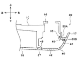
- FIG. 8 is a cross-sectional view taken along line VIII-VIII in FIG. 7;
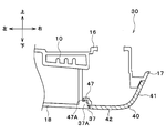
- FIG. 8 is a cross-sectional view taken along the line IX-IX in FIG.
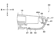
- FIG. 8 is a cross-sectional view taken along the line XX in FIG. 7;
- the vehicle air conditioner 1 As shown in FIGS. 1 to 3, the vehicle air conditioner 1 according to the present embodiment is disposed at a ceiling R of the vehicle room C in order to make the inside of the vehicle room C of the vehicle a comfortable air conditioning environment.
- the inside of case 10 accommodates the ventilation fan 20 grade
- An air inlet 12 and an air outlet 14 to be described later are formed in the case 10 of the vehicle air conditioner 1 and communicate with the inside of the vehicle interior C, respectively. Therefore, the air conditioning system 1 for vehicles circulates the compartment C by sucking the air A in the compartment C from the suction port 12 by the operation of the blower fan 20 and supplying the air A to the inside of the compartment C from the respective outlets 14.
- the flow of air A can be generated. That is, the vehicle air conditioner 1 according to the present embodiment functions as a ceiling-mounted circulator.
- the vehicle air conditioner 1 is mounted on a so-called minivan type vehicle of three-row seats.
- a plurality of seats S are disposed in a cabin C of the vehicle.
- the plurality of sheets S are referred to as a first row seat, a second row seat, and a third row seat, from the front to the rear of the vehicle.
- the first row seat is constituted by the seat S corresponding to the driver's seat and the front passenger seat.
- the second-row seat and the third-row seat are, for example, configured of bench-type seats S on which three occupants can sit.
- the vehicle air conditioner 1 is disposed behind the first row seat and in front of the second row seat in the ceiling R of the cabin C, and is located in the central portion in the vehicle width direction. ing.
- the case 10 of the vehicle air conditioner 1 is fixed to the fixed bracket B disposed on the vehicle body of the vehicle, and the arrangement of the vehicle air conditioner 1 with respect to the passenger compartment C can be determined. Specifically, in order to allow the suction port 12 and the blowout port 14 formed on the lower surface 18 of the case 10 to communicate with the vehicle compartment C, the lower part of the case 10 of the vehicle air conditioner 1 is on the vehicle compartment C side. It is arranged to be exposed.
- part of the side portion 17 including the lower surface 18 of the case 10 and the side surface disposed along the outer edge of the lower surface 18 is lower than the roof head lining that constitutes the ceiling R. Will be placed.
- the vehicle air conditioner 1 is configured to accommodate the blower fan 20 inside the case 10 disposed in the ceiling R of the vehicle.
- the detailed configuration of the configuration on the lower surface 18 side of the case 10 and the internal configuration of the case 10 are omitted, and the positional relationship between the respective configurations is indicated by a broken line.
- the case 10 of the vehicle air conditioner 1 extends from the fan housing portion 11 for housing the blower fan 20 and the fan housing portion 11 in the vehicle width direction of the vehicle. It has a pair of air flow path parts 13.
- the fan housing portion 11 constitutes a central portion of the case 10 in the vehicle width direction.
- the fan housing portion 11 has a cylindrical space inside, and accommodates the blower fan 20.
- a suction port 12 is formed on the lower surface 18 of the fan housing 11 to communicate the inside of the case 10 and the fan housing 11 with the inside of the compartment C. Therefore, when the operation of the blower fan 20 is started, the air A in the passenger compartment C is sucked into the fan housing 11 from the inside of the passenger compartment C via the suction port 12.
- the blower fan 20 is disposed to face the suction port 12 inside the fan housing portion 11, sucks the air in the compartment C from the suction port 12, and passes through the blower ports 14 of the respective blower flow path portions 13. The air is blown into the case 10 as air blown into the room.
- the blower fan 20 is disposed inside the fan housing portion 11 by being fixed to a vehicle body member (for example, a roof reinforcement) in the ceiling portion R.
- the blower fan 20 is an electric blower that drives a centrifugal multiblade fan (that is, a sirocco fan) by an electric motor.
- the centrifugal multiblade fan has a substantially cylindrical shape, and has a large number of vanes on the radially outer side.
- the electric motor constitutes a part of the blower fan 20, and has a drive shaft extending along the vertical direction of the vehicle. Since the centrifugal multi-blade fan is fixed to the drive shaft of the electric motor, the blower fan 20 operates the electric motor so that the air drawn into the shaft core of the centrifugal multi-blade fan through the suction port 12 is a fan It can blow off to the radial direction outer side in the accommodating part 11.
- the blower fan 20 is an example of the blower in the present disclosure.
- the rotational speed (the amount of air to be blown) of the centrifugal multi-blade fan in the blower fan 20 is controlled by a control voltage output from an air conditioning controller (not shown).
- a plurality of fixing portions 15 are disposed in the upper portion of the fan housing portion 11.
- the fixing portion 15 is used when fixing the case 10 to a vehicle body member (for example, a roof reinforcement) disposed at an upper portion of the ceiling portion R.
- the pair of air flow path portions 13 are portions extending from the fan housing portion 11 along the vehicle width direction of the vehicle.
- the inside of each air flow passage portion 13 communicates with the inside of the fan housing portion 11. Therefore, the inside of each air flow passage portion 13 functions as an air flow passage through which the air blown out from the fan housing portion 11 with the operation of the air blowing fan 20.
- An air outlet 14 is formed on the lower surface 18 of each air flow passage portion 13, and the inside of the air flow passage portion 13 and the vehicle interior C are communicated with each other. Accordingly, the air that has flowed through the inside of the air flow passage portion 13 is supplied to the inside of the passenger compartment C via the air outlet 14.
- each air outlet 14 is formed in a slit shape extending along the vehicle width direction on the vehicle rear side of the lower surface 18 of each air flow passage portion 13. Therefore, in the vehicle air conditioner 1, the air supplied from the respective air outlets 14 is blown out toward the rear side of the vehicle as shown by the arrow A in FIG. 2.
- each bolt attachment part 16 is formed in the upper surface by the side of the front-end
- the bolt mounting portions 16 are disposed at positions symmetrical with each other in the case 10 of the vehicle air conditioner 1. Therefore, the case 10 of the vehicle air conditioner 1 can be accurately fixed at a predetermined position on the ceiling R of the vehicle.
- the tip end portion of the air flow passage portion 13 means an end portion on the opposite side of the fan accommodation portion 11 in each air flow passage portion 13 and is a portion positioned outside in the vehicle width direction.
- a cover attachment portion 30 is formed at the tip of each air flow passage portion 13.
- the cover attachment portion 30 is a portion located downward from the ceiling portion R and exposed to the compartment C side at the tip end portion of the air flow passage portion 13, and is a portion to which a cover member 40 described later is attached.
- the cover mounting portion 30 has a portion of the side portion 17 and a portion of the lower surface 18 at the tip of the air flow passage portion 13 in the case 10.
- the cover attachment 30 functions as an outer edge in the present disclosure. The specific configuration of the cover mounting portion 30 will be described later with reference to the drawings.
- Each cover member 40 is attached to a cover attaching portion 30 which is a part of the case 10, and is disposed so as to cover the cover attaching portion 30.
- the cover member 40 plays a role of enhancing the design of the vehicle air conditioner 1 when viewed from the compartment C by covering the cover mounting portion 30.
- the specific configuration of the cover member 40 will be described in detail later with reference to the drawings.
- the vehicle air conditioner 1 according to the present embodiment includes the left end in the left-right direction of the air flow channel portion 13 and the right end in the left-right direction of the air flow passage portion 13. At the tip end, each has a cover mounting portion 30.
- the two cover attachment portions 30 have the same basic configuration except for the arrangement positions to be respectively disposed on the left side and the right side of the vehicle. Therefore, in the description of the specific configuration of the cover mounting portion 30, the cover mounting portion 30 located on the right side of the vehicle will be described as an example.
- the cover attachment portion 30 of the vehicle air conditioner 1 in the present embodiment is a tip end portion of each air flow passage portion 13 and a portion exposed to the compartment C side below the ceiling portion R means.
- each cover attachment portion 30 has a part of the side part 17 that constitutes the air flow path part 13 and a part of the lower surface 18 of the air flow path part 13. . That is, a part of the side part 17 corresponds to a part of the side part 17 below the ceiling R.
- the cover attachment part 30 comprises the outer edge of the part exposed to the compartment C side in the vehicle air conditioner 1. That is, the cover attachment portion 30 corresponds to the outer edge portion in the present disclosure.
- the cover mounting portion 30 has an insertion opening 35 and a pair of upper engaging portions 36 in a part of the side portion 17 constituting the cover mounting portion 30.
- the insertion opening 35 is formed by penetrating a plate-like portion extending downward from the upper surface at the tip end portion of the air flow passage portion 13 in the vehicle width direction. That is, since the insertion opening 35 is uneven in the side portion 17 of the cover mounting portion 30 and is recessed with respect to the other portion of the side portion 17, the fitting in the present disclosure is realized. Act as a department.
- the opening edge of the insertion opening 35 includes an upper opening edge 35A and a lower opening edge 35B.
- the upper opening edge 35A constitutes a portion of the opening edge of the insertion opening 35 located on the vehicle upper side
- the lower opening edge 35B constitutes a portion of the opening edge of the insertion opening 35 located on the vehicle lower side doing.
- the lower opening edge 35 ⁇ / b> B is located outside the case 10 relative to the upper opening edge 35 ⁇ / b> A in the horizontal direction (i.e., the vehicle width direction) of the case 10.
- the pair of upper engaging portions 36 is disposed to sandwich the insertion opening 35 and is formed in a plate shape extending downward from the upper surface of the tip end portion of the air flow path portion 13.
- the pair of upper engaging portions 36 is configured by the upper engaging portion 36 positioned on the vehicle front side with respect to the insertion opening 35 and the upper engaging portion 36 positioned on the vehicle rear side with respect to the insertion opening 35 It is done.
- Each upper engagement portion 36 is formed such that the lower end portion of the upper engagement portion 36 is at a predetermined position below the upper opening edge 35A.
- a lower engaging portion 37 is formed on the lower surface 18 side of the cover mounting portion 30.
- the lower engagement portion 37 is formed by extending the end of the lower surface 18 of the cover member 40 outward in the vehicle width direction, and is formed in a plate shape having a thickness in the vehicle vertical direction. Therefore, a part of the cover member 40 can be brought into contact with the upper surface of the lower engaging portion 37.
- an engagement protrusion 37A is formed on the upper surface of the lower engagement portion 37.
- the engagement projection 37A is formed to project upward from the upper surface of the lower engagement portion 37 at a predetermined position of the lower engagement portion 37.
- the upper end portion of the engagement protrusion 37A is disposed to have a gap on the inner side in the vehicle width direction. Thereby, the claw portion 47A of the lower locking claw 47 described later can be engaged with the upper end portion of the engagement protrusion 37A.
- the cover mounting portion 30 in the vehicle air conditioner 1 is disposed at the tip of the case 10 on the right and left sides in the left-right direction.
- the cover members 40 are configured to be attached to the respective cover attachment portions 30.
- the cover member 40 has the same basic configuration except for the arrangement position of being disposed on the right and left sides of the vehicle in the left and right direction. Therefore, in the description of the specific configuration of the cover member 40, the cover member 40 attached to the cover attachment portion 30 on the right side will be described as an example.
- the cover member 40 has a side covering portion 41 and a lower covering portion 42, and by being attached to the cover attaching portion 30, It is comprised so that the front-end
- the side covering portion 41 is a portion covering the side portion 17 in the cover mounting portion 30, and the lower covering portion 42 constitutes the lower portion of the cover member 40, and together with the lower surface 18 of the cover mounting portion 30, the vehicle air conditioner It is a part which constitutes the lower surface of 1.
- the cover member 40 is comprised so that the whole cover attachment part 30 may be covered by connecting the side cover part 41 and the lower cover part 42 by a curved surface.
- the cover member 40 configured in this manner includes the protruding piece 45, the pair of upper locking claws 46, the lower locking claw 47, and the lower restriction pieces 48. Have.
- the protruding piece 45 has a concavo-convex shape based on the side covering portion 41 of the cover member 40, and is a prismatic portion formed so as to protrude in the horizontal direction from the side covering portion 41.
- the projecting piece 45 extends from the side covering portion 41 inward in the vehicle width direction (that is, in the left direction in the case of FIGS. 5 and 6).
- the cross-sectional area of the projecting piece 45 is smaller than the opening area of the insertion opening 35 so as to have a dimension relation of clearance fit with the opening area of the insertion opening 35.
- the projecting piece 45 can insert the insertion opening 35 in the cover attachment portion 30. Further, since the projecting piece 45 is formed so as to horizontally project inward in the vehicle width direction from the side covering portion 41 of the cover member 40, the projecting piece 45 corresponds to the fitting portion in the present disclosure.
- the pair of upper locking claws 46 are disposed to sandwich the protruding piece 45, and extend in the horizontal direction from the side covering portion 41 of the cover member 40.
- the pair of upper locking claws 46 are the upper locking claw 46 located on the vehicle front side with respect to the protruding piece 45, and the upper locking claw 46 located on the vehicle rear side with respect to the protruding piece 45. It is composed of
- a claw 46A is formed at the tip of each upper locking claw 46.
- the claw portion 46A is formed on the upper surface side of the tip end portion of the upper locking claw 46 and protrudes upward. Further, the upper end portion of the claw portion 46A of the upper locking claw 46 is formed to be above the lower end of the upper engaging portion 36.
- the lower restricting piece 48 is a restricting piece formed along the end of the lower cover 42 and is located above the end of the lower cover 42. That is, the lower regulation piece 48 constitutes a step with respect to the end of the lower covering portion 42.
- the lower restriction piece 48 contacts the upper surface of the lower engagement portion 37 from above, and the cover member 40 to the cover attachment portion 30. Downward displacement can be regulated.
- the lower locking claw 47 is formed at a position corresponding to the engaging protrusion 37A of the lower engaging portion 37 at the end of the lower covering portion 42. As shown in FIG. 5, the lower locking claw 47 extends horizontally from above the lower restriction piece 48. Therefore, when the cover member 40 is attached to the cover attaching portion 30, the lower locking claw 47 contacts the engaging projection 37A from above.
- a claw portion 47A is formed at the tip of the lower locking claw 47.
- the claw portion 47A is formed on the lower surface side of the tip end portion of the lower locking claw 47 and is formed to project downward.
- the lower end of the claw portion 47A of the lower locking claw 47 is formed to be lower than the upper end of the engagement projection 37A.
- each lower locking claw 47 engages with the engaging projection 37A of each lower engaging portion 37 in the cover attaching portion 30.
- the cover member 40 is attached to the cover mounting portion 30 positioned on the right side in the left-right direction. explain.
- the fitting of the insertion opening 35 and the projecting piece 45 and the upper engagement portion 36 And engagement between the lower engagement portion 37 and the lower engagement claw 47 is performed.
- FIG. 8 is a cross-sectional view showing the state of the insertion opening 35 and the projecting piece 45 when the cover member 40 is attached to the cover attachment portion 30 on the right side in the left-right direction.
- the projecting piece 45 of the cover member 40 is inserted into the insertion opening 35 of the cover attachment portion 30.
- the opening edge of the projecting piece 45 is positioned around the direction in which the projecting piece 45 extends, so that the projecting piece 45 in the direction perpendicular to the axial direction (that is, in the front and rear direction and up and down direction in the vehicle) The amount of displacement is suppressed to the range inside the insertion opening 35.
- the cover member 40 when an impact acts in a state where the cover member 40 is attached to the cover attachment portion 30, the cover member 40 is affected by the impact and the weight of the cover member 40, and the lower opening edge 35B of the insertion opening 35 And a downward turning movement about the contact portion of the protruding piece 45.
- the projecting piece 45 inclines the insertion opening 35 as the cover member 40 rotates. It is conceivable that it will be in the state inserted from the lower side.
- the lower opening edge 35B of the insertion opening 35 is located outside the upper opening edge 35A in the vehicle width direction. Therefore, even when the cover member 40 attempts to pivot about the contact portion between the lower opening edge 35B and the projection piece 45, the tip end portion of the projection piece 45 which is about to be displaced upward is the insertion opening It will be in contact with the upper opening edge 35A of 35, and can maintain a horizontal state.
- the vehicle air conditioner 1 suppresses the rotation of the cover member 40 about the contact portion between the lower opening edge 35B and the projecting piece 45 in response to an impact, and the case 10 disposed in the ceiling R Falling off of the cover member 40 can be prevented.
- the lower restriction piece 48 of the cover member 40 is disposed in contact with the upper surface of the lower engagement portion 37 of the cover attachment portion 30.
- the lower regulation piece 48 which is the lower part of the cover member 40 is supported from the lower side by the lower engagement portion 37, and the downward displacement of the cover member 40 can be suppressed.
- the fitting structure by the insertion opening 35 and the projecting piece 45 and the supporting structure by the lower engagement portion 37 and the lower restriction piece 48 are between the cover attachment portion 30 and the cover member 40.
- the vehicle is disposed at different positions in the vehicle vertical direction and the vehicle width direction, and restricts the displacement of the cover member 40 with respect to the cover mounting portion 30.
- the vehicle air conditioner 1 can efficiently regulate the displacement of the cover member 40 with respect to the cover mounting portion 30, and can prevent the cover member 40 from falling off due to an impact.
- FIG. 9 is a cross-sectional view showing the state of the engagement protrusion 37A and the lower locking claw 47 when the cover member 40 is attached to the cover attachment portion 30 on the right side in the left-right direction.
- the lower locking claw 47 of the cover member 40 is arranged to engage with the engaging projection 37 ⁇ / b> A of the cover mounting portion 30 from above the engaging projection 37 ⁇ / b> A .
- the claw portion 47A of the lower locking claw 47 enters a gap located at the upper end portion of the engagement protrusion 37A and engages with the engagement protrusion 37A.
- the positional relationship in the lower part of the cover attaching part 30 and the cover member 40 can be accurately determined by the engaging projection 37A and the lower locking claw 47, and the cover member 40 It is possible to suppress the downward displacement of the vehicle and the vehicle width direction.
- the cover member relative to the cover mounting portion 30 is used as a cover member. It is necessary to displace 40 greatly upward. In other words, the engagement between the engagement projection 37A and the lower locking claw 47 can be made stronger than when the claw portion 47A is not present, and the cover member 40 can be prevented from coming off.
- the lower restriction piece 48 of the cover member 40 is disposed in contact with the upper surface of the lower engagement portion 37 of the cover attachment portion 30. Therefore, according to the vehicle air conditioner 1, in addition to the engagement of the engagement projection 37A and the lower locking claw 47, the cover member 40 is restricted by the restriction by the lower engagement portion 37 and the lower restriction piece 48. The downward displacement can be further reliably suppressed.
- FIG. 10 is a cross-sectional view showing the state of the upper engagement portion 36 and the upper locking claw 46 when the cover member 40 is attached to the right cover attachment portion 30 in the left-right direction.
- the upper locking claw 46 of the cover member 40 is on the upper side with respect to the upper engagement portion 36 of the cover attachment portion 30.
- the engagement portion 36 is arranged to be engaged from below.
- the positional relationship between the cover mounting portion 30 and the upper portion of the cover member 40 can be accurately determined by the upper engaging portion 36 and the upper engaging claw 46. An upward displacement can be suppressed.
- a claw portion 46A is disposed at the tip of the upper locking claw 46, and the upper end of the claw portion 46A is engaged with the lower end of the upper engagement portion 36 in a state of being positioned above. Therefore, in order to release the engagement between the upper engagement portion 36 and the upper engagement claw 46, the cover member 40 needs to be displaced largely upward with respect to the cover attachment portion 30.
- the positional relationship in the upper portion of the cover mounting portion 30 and the cover member 40 can be accurately determined by the engagement of the upper engagement portion 36 and the upper engagement claw 46, and the cover member The displacement in the upper direction and the vehicle width direction of the vehicle 40 can be suppressed.
- the cover member 40 can be attached at a predetermined position on the cover attaching portion 30 with high accuracy.
- the engagement of the claws 47 can suppress the displacement of the cover member 40 due to the impact, and the cover member 40 can be prevented from coming off.
- the vehicle air conditioner 1 has the blower fan 20 inside the fan accommodation portion 11 of the case 10 in the ceiling R of the cabin C, and each air flow passage portion
- the cover member 40 is attached to the cover attaching part 30 formed in the front-end
- the vehicle air conditioner 1 operates the blower fan 20 to suck in the air A in the compartment C from the suction port 12 of the fan housing portion 11, and via the blower passage portions 13 and the blower outlets 14.
- the air A can be supplied to the passenger compartment C. That is, the vehicle air conditioner 1 functions as a ceiling-arranged circulator and can improve the comfort in the passenger compartment C.
- the vehicle air conditioner 1 can suppress the displacement of the cover member 40 with respect to the cover mounting portion 30 in the vehicle vertical direction, and can prevent the cover member 40 from falling off due to an impact.
- the fitting by the insertion opening 35 and the projecting piece 45 and the engagement by the lower engagement portion 37 and the lower engagement claw 47 The displacement of the cover member 40 relative to the cover mounting portion 30 can be regulated at two different places.
- the vehicle air conditioner 1 restricts the displacement of the cover member 40 with respect to the cover mounting portion 30 even when an impact is applied to the vehicle air conditioner 1, thereby suppressing the falling off of the cover member 40.
- the cover mounting portion 30 is formed with an insertion opening 35
- the cover member 40 is formed with a projecting piece 45.
- the projecting piece 45 is inserted through the insertion opening 35.
- the cover member 40 can be prevented from falling off by using the relatively simple shapes of the insertion opening 35 and the protruding piece 45.
- the opening edge of the insertion opening 35 is disposed so as to surround the projecting piece 45 all around. That is, according to the vehicle air conditioner 1, the displacement with the cover member 40 in various directions is suppressed since contact with the opening edge of the insertion opening 35 is possible in all directions perpendicular to the extending direction of the protruding piece 45. can do.
- the lower opening edge 35B of the insertion opening 35 is located outside the upper opening edge 35A of the insertion opening 35 in the vehicle width direction.
- the lower locking claw 47 has a claw portion 47A protruding downward at its tip end portion, and is engaged with the engagement projection 37A from above using the claw portion 47A. ing. As a result, the amount of displacement necessary for releasing the engagement of the lower locking claw 47 with the engagement projection 37A of the lower engagement portion 37 is increased, so that the cover member from the cover mounting portion 30 40 can be prevented from falling off.
- the upper side engaging portion 36 is formed in the cover mounting portion 30, and the upper engaging claw 46 is formed in the cover member 40. Then, according to the vehicle air conditioner 1, displacement of the cover member 40 in the vertical direction of the vehicle at the upper portion of the cover attachment portion 30 and the cover member 40 by the engagement of the upper engagement portion 36 and the upper engagement claw 46. It is possible to prevent the cover member 40 from falling off due to an impact.
- the vehicle air conditioner 1 in addition to the fitting of the insertion opening 35 and the projecting piece 45 and the engagement of the lower engagement portion 37 and the lower engagement claw 47, the upper engagement portion 36 and the upper side The engagement by the locking pawl 46 can be coordinated.
- the vehicle air conditioner 1 can further suppress the displacement of the cover member 40 with respect to the cover mounting portion 30, and can prevent the cover member 40 from falling off due to an impact.
- the displacement direction (that is, the vehicle upper direction) of the cover member 40 for releasing the engagement between the lower engagement portion 37 and the lower engagement claw 47 is the same as that of the upper engagement portion 36 and the upper engagement claw 46. It will be in the direction to strengthen the engagement. For this reason, the vehicle air conditioner 1 can suppress drop-off
- a claw portion 46A protruding upward is formed at the tip end portion of the upper locking claw 46.
- the amount of displacement necessary for releasing the engagement between the upper engaging portion 36 and the upper locking claw 46 is increased.
- the vehicle air conditioner 1 can prevent the cover member 40 from falling off by strengthening the engagement between the upper engagement portion 36 and the upper engagement claw 46.
- a ceiling-mounted circulator is used as the vehicle air conditioner according to the present disclosure, but the present invention is not limited to this aspect.
- the vehicle air conditioner according to the present disclosure can adopt various modes as long as it is disposed on the ceiling of the cabin and can air-condition the cabin.
- a vehicle air conditioner 1 a vapor compression type refrigeration cycle is accommodated in a case 10 together with a blower fan in a case 10, and conditioned air that has been subjected to temperature control using the refrigeration cycle is supplied to the vehicle interior May be
- the insertion opening 35 is formed in the cover mounting portion 30 as the fitting portion according to the present disclosure
- the projecting piece 45 is formed in the cover member 40 as the fitting portion according to the present disclosure.
- a convex portion such as a protruding piece may be formed on the cover attachment portion 30 which is the case side, and a concave portion such as an insertion opening may be formed on the cover member 40 side.
- the penetration opening 35 was comprised so that the plate-like-part in the cover attaching part 30 might be penetrated, it limits to this aspect It is not something to do.
- a recess configured to be able to be fitted with a convex portion such as the protruding piece 45 may be used.
Landscapes
- Physics & Mathematics (AREA)
- Thermal Sciences (AREA)
- Engineering & Computer Science (AREA)
- Mechanical Engineering (AREA)
- Air-Conditioning For Vehicles (AREA)
Abstract
車両用空調装置(1)は、車室(C)の天井部(R)において、ケース(10)のファン収容部(11)に送風ファン(20)を有して構成されており、ファン収容部(11)の吸込口(12)から車室(C)内の空気を吸いこみ、送風流路部(13)及び吹出口(14)を介して車室(C)に空気を供給する。送風流路部(13)の先端部分に形成されたカバー取付部(30)には、カバー部材(40)が取り付けられる。カバー取付部(30)には、挿通開口(35)と下側係合部(37)が形成されている。カバー部材(40)の側方被覆部(41)には突出片(45)が形成されており、カバー部材(40)の下部には下側係止爪(47)が形成されている。カバー部材(40)を取り付ける場合、挿通開口(35)には、カバー部材(40)の突出片(45)が挿通される。下側係止爪(47)は、下側係合部(37)の係合突部(37A)に対して上方から係合する。
Description
本出願は、当該開示内容が参照によって本出願に組み込まれた、2017年7月31日に出願された日本特許出願2017-148192号を基にしている。
本開示は、車両の天井に配置される車両用空調装置に関する。
従来、車両の車室内を空調する車両用空調装置の一つとして、車両の天井部分に配置される車両用空調装置が知られている。
特許文献1には、このような車両用空調装置として天井サーキュレータが記載されている。当該天井サーキュレータは、天井部に配置されたケース内部の送風機の作動によって、ケースに形成された取入部から車室内の空気を吸い込み、ケースにおける異なる部分に形成された吹出部から車室内に送風するように構成されている。
特許文献1のような車両用空調装置において、天井部に配置されるケースは、その一部が車室の天井部から車室の内側に露出するように配置される。そして、車室の内側に露出するケースの外縁には、デザイン性の向上等を目的として、カバー部材が配置される場合がある。
このようにケースに対してカバー部材が取り付けられている構成の場合、車両用空調装置に対して衝撃が加わってしまうと、カバー部材がケースからはずれて車室の内側に脱落することが想定される。
例えば、近年の車両において安全性の観点から配置されるカーテンサイドエアバックの発動に起因する衝撃によって、天井部に配置されたケースからカバー部材が脱落することが想定される。この場合、カバー部材は天井部から車室の内部に脱落する為、カバー部材が車室内の乗員に接触してしまう虞があり、例えば、乗員の頭部に接触してしまうことが懸念される。
本開示は、これらの点に鑑みてなされており、車室の天井部に配置された車両用空調装置に関し、衝撃によるカバー部材の脱落を抑制可能な車両用空調装置を提供することを目的とする。
本開示の一態様に係る車両用空調装置は、送風機、ケース、およびカバー部材を有している。送風機は、車室に対する空気の流れを発生させる。ケースは、車室の天井部に対して下面及び側方部の一部分が車室に露出するように配置され、送風機を内部に収容する。カバー部材は、車室に露出したケースの下面の一部分及び側方部の一部分を含む外縁部に対して取り付けられ、外縁部を覆う。ケースは、嵌合部と下側係合部を有している。嵌合部は、外縁部における側方部に形成され、水平方向に対して凹凸を為す。下側係合部は、外縁部における下面に形成されている。カバー部材は、被嵌合部と下側係止爪を有している。被嵌合部は、外縁部における側方部を覆う側方被覆部において、水平方向に対して凹凸を為すように形成され、嵌合部と嵌合する。下側係止爪は、カバー部材の下部に形成され、下側係合部の上方にて下側係合部と係合する。
車両用空調装置は、送風機と、ケースとを有しており、ケースの外縁部に対してカバー部材が取り付けられている。この為、車両用空調装置は、ケースの内部に配置された送風機を作動させることで、ケースを介して、車室に対する空気の流れを発生させることができ、車室の内部における快適性を向上させることができる。
又、車両用空調装置において、ケースの外縁部に対してカバー部材を取り付ける場合には、ケースにおける嵌合部と、カバー部材の被嵌合部とを嵌合させている。この結果、車両用空調装置によれば、ケースの嵌合部とカバー部材の被嵌合部との嵌合構造によって、ケースに対するカバー部材の変位量を抑制することができる。
そして、車両用空調装置においては、ケースの下側係合部とカバー部材の下側係止爪によって、ケースに対するカバー部材の位置に関する上下方向への変位を規制することができる。
即ち、本開示の車両用空調装置によれば、嵌合部と被嵌合部に加え、下側係合部と下側係止爪という構成によって、ケースに対するカバー部材の変位を異なる二カ所で規制することができる。これにより、車両用空調装置は、車両用空調装置に衝撃が加わった場合であっても、ケースに対するカバー部材の変位量を規制して、カバー部材の脱落を抑制することができる。
以下、実施形態について図に基づいて説明する。以下の実施形態において、互いに同一もしくは均等である部分には、図中、同一符号を付してある。
以下の説明で前後左右上下の方向を用いて説明するときは、車両用シートに着座した乗員から見た前後左右上下の方向を示すものとする。そして、各図に適宜示す矢印についても同様の定義を用いており、車両幅方向とは左右方向に相当している。
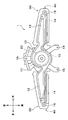
図1~図3に示すように、本実施形態に係る車両用空調装置1は、車両の車室C内を快適な空調環境にする為に、車室Cの天井部Rに配置されており、ケース10の内部に送風ファン20等を収容して構成されている。
車両用空調装置1のケース10には、後述する吸込口12及び吹出口14が形成されており、それぞれ車室Cの内部と連通している。従って、車両用空調装置1は、送風ファン20の作動によって、車室Cの空気Aを吸込口12から吸い込み、各吹出口14から車室Cの内部へ供給することで、車室Cを循環する空気Aの流れを発生させることができる。即ち、本実施形態に係る車両用空調装置1は、天井設置型のサーキュレータとして機能している。
図2に示すように、本実施形態に係る車両用空調装置1は、三列シートの所謂ミニバンタイプの車両に搭載されている。車両の車室Cには、複数のシートSが配置されている。複数のシートSは、車両前方から後方に向かって、一列目シート、二列目シート、三列目シートと呼ばれる。
一列目シートは、運転席及び助手席に相当するシートSによって構成されている。そして、二列目シート及び三列目シートは、例えば、それぞれ3人の乗員が着座可能なベンチタイプのシートSによって構成されている。
車両用空調装置1は、図2に示すように、車室Cの天井部Rにおいて、一列目シートの後方且つ二列目シートの前方に配置されており、車両幅方向における中央部分に位置している。
そして、車両用空調装置1のケース10は、車両の車体に配置された固定ブラケットBに対して固定され、車室Cに対する車両用空調装置1の配置を定められる。具体的には、ケース10の下面18に形成された吸込口12及び吹出口14を車室Cと連通させる為に、車両用空調装置1は、ケース10の下側部分が車室C側に露出するように配置される。
即ち、図2に示すように、ケース10の下面18と、下面18の外縁に沿って配置された側面を含む側方部17の一部分は、天井部Rを構成するルーフヘッドライニングよりも下側に配置される。
次に、本実施形態に係る車両用空調装置1の具体的構成について、図1~図3を参照しつつ詳細に説明する。上述したように、車両用空調装置1は、車両の天井部Rに配置されるケース10内部に、送風ファン20を収容して構成されている。尚、図3において、ケース10の下面18側の構成やケース10の内部構成については詳細な図示を省略し、各構成の位置関係を破線で示す。
図1、図3に示すように、本実施形態に係る車両用空調装置1のケース10は、送風ファン20を収容するファン収容部11と、ファン収容部11から車両の車幅方向にそれぞれ伸びる一対の送風流路部13とを有している。
ファン収容部11は、ケース10における車両幅方向の中央部分を構成している。ファン収容部11は、その内部に円柱状の空間を有しており、送風ファン20を収容している。
そして、ファン収容部11の下面18には、吸込口12が形成されており、ケース10及びファン収容部11の内部と車室C内とを連通している。従って、送風ファン20の作動を開始すると、車室Cの空気Aは、車室C内部から吸込口12を介して、ファン収容部11の内部に吸い込まれる。
送風ファン20は、ファン収容部11の内部において吸込口12に対向するように配置されており、吸込口12から車室C内の空気を吸い込み、各送風流路部13の吹出口14を介して、社室内へ送風される空気としてケース10内部へ送風する。
送風ファン20は、天井部Rにおける車体部材(例えば、ルーフリインフォースメント)に対して固定されることで、ファン収容部11の内部に配置されている。送風ファン20は、遠心多翼ファン(即ち、シロッコファン)を電動モータにて駆動する電動送風機である。遠心多翼ファンは略円筒形を為しており、径方向外側に多数の羽根を有している。
そして、電動モータは、送風ファン20の一部を構成しており、車両上下方向に沿って伸びる駆動軸を有している。遠心多翼ファンは電動モータの駆動軸に固定されている為、送風ファン20は、電動モータを作動させることで、吸込口12を介して遠心多翼ファンの軸芯部に吸い込んだ空気をファン収容部11における径方向外側へ吹き出させることができる。
従って、送風ファン20は、本開示における送風機の一例である。そして、送風ファン20における遠心多翼ファンの回転数(送風する空気の量)は、図示しない空調制御装置から出力される制御電圧によって制御される。
又、ファン収容部11の上部には、複数の固定部15が配置されている。固定部15は、天井部Rの上部に配置された車体部材(例えば、ルーフリインフォースメント)に対して、ケース10を固定する際に用いられる。
そして、一対の送風流路部13は、それぞれ、ファン収容部11から車両の車幅方向に沿って伸びた部分である。各送風流路部13の内部は、ファン収容部11の内部と連通している。従って、各送風流路部13の内部は、送風ファン20の作動に伴いファン収容部11から吹き出された空気が流れる送風流路として機能する。
各送風流路部13の下面18には、吹出口14が形成されており、送風流路部13の内部と車室Cとを連通している。従って、送風流路部13の内部を流れた空気は、吹出口14を介して、車室Cの内部に供給される。
又、各吹出口14は、各送風流路部13の下面18における車両後方側において、車両幅方向に沿って伸びるスリット状に形成されている。従って、車両用空調装置1においては、各吹出口14から供給される空気は、図2において矢印Aで示すように、車両後方側に向かって吹き出される。
そして、図1、図3に示すように、各送風流路部13の先端部側の上面には、ボルト取付部16が形成されている。各ボルト取付部16は、車両の天井部Rにおける上方に配置された固定ブラケットB(図2参照)に対して、ボルト及びナットによって、ケース10を締結固定する際に用いられる。
又、各ボルト取付部16は、車両用空調装置1のケース10において、相互に左右対称となる位置に配置されている。従って、車両用空調装置1のケース10を、車両の天井部Rにおける所定位置に精度よく固定することができる。
尚、送風流路部13の先端部とは、各送風流路部13において、ファン収容部11とは逆側の端部を意味し、車両幅方向における外側に位置する部分である。
図1、図3に示すように、各送風流路部13の先端部には、カバー取付部30がそれぞれ形成されている。カバー取付部30は、送風流路部13の先端部において、天井部Rから下方に位置し車室C側に露出した部分であり、後述するカバー部材40が取り付けられる部分である。
つまり、カバー取付部30は、ケース10における送風流路部13の先端部にて、側方部17の一部分と、下面18の一部分を有している。カバー取付部30は、本開示における外縁部として機能する。カバー取付部30の具体的な構成については、後に図面を参照しつつ説明する。
そして、各カバー部材40は、ケース10の一部であるカバー取付部30に対してそれぞれ取り付けられ、カバー取付部30を覆うように配置される。カバー部材40は、カバー取付部30を覆うことによって、車室C側から見た場合の車両用空調装置1のデザイン性を高める役割を果たしている。カバー部材40の具体的構成については、後に図面を参照しつつ詳細に説明する。
次に、本実施形態に係る車両用空調装置1におけるカバー取付部30の具体的構成について、図4を参照しつつ詳細に説明する。図1、図3に示すように、本実施形態に係る車両用空調装置1は、送風流路部13のうち左右方向の左側の先端部と、送風流路部13のうち左右方向の右側の先端部に、それぞれカバー取付部30を有している。
この2つのカバー取付部30は、車両の左側と右側にそれぞれ配置されるという配置位置を除いて、基本的構成を同じくするものである。従って、カバー取付部30の具体的構成に関する説明では、車両の右側に位置するカバー取付部30を例に挙げて説明する。
上述したように、本実施形態における車両用空調装置1のカバー取付部30は、各送風流路部13の先端部であって、天井部Rの下方にて車室C側に露出した部分を意味する。
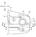
従って、図4に示すように、各カバー取付部30は、送風流路部13を構成する側方部17の一部と、送風流路部13における下面18の一部とを有している。側方部17の一部とは、即ち、側方部17の内、天井部Rよりも下方となる部分に相当する。これにより、カバー取付部30は、車両用空調装置1にて車室C側に露出した部分の外縁を構成する。即ち、カバー取付部30は、本開示における外縁部に相当する。
そして、カバー取付部30は、カバー取付部30を構成する側方部17の一部において、挿通開口35と、一対の上側係合部36とを有している。
図4に示すように、挿通開口35は、送風流路部13の先端部における上面から下方に伸びる板状部を、車両幅方向に貫通するように開口して形成されている。即ち、挿通開口35は、カバー取付部30における側方部17において凹凸を為しており、側方部17の他の部分に対して凹状に窪んで構成されている為、本開示における嵌合部として機能する。
図4、図8等に示すように、挿通開口35における開口縁は、上側開口縁35Aと、下側開口縁35Bとを含んでいる。上側開口縁35Aは、挿通開口35の開口縁の内、車両上側に位置する部分を構成し、下側開口縁35Bは、挿通開口35の開口縁の内、車両下側に位置する部分を構成している。
図8に示すように、下側開口縁35Bは、ケース10における水平方向(即ち、車両幅方向)に関して、上側開口縁35Aよりも、ケース10の外側に位置している。
そして、一対の上側係合部36は、挿通開口35を挟むように配置されており、送風流路部13の先端部における上面から下方に伸びる板状に形成されている。換言すると、一対の上側係合部36は、挿通開口35に対して車両前方側に位置する上側係合部36と、挿通開口35に対して車両後方側に位置する上側係合部36によって構成されている。
各上側係合部36は、上側係合部36の下端部が上側開口縁35Aよりも下方である予め定められた位置になるように形成されている。
図4に示すように、カバー取付部30を構成する下面18側には、下側係合部37が形成されている。下側係合部37は、カバー部材40の下面18の端部を車両幅方向の外側に向かって延出して形成されており、車両上下方向に厚みを有する板状に形成されている。従って、下側係合部37の上面に対して、カバー部材40の一部を接触させることができる。
又、下側係合部37の上面には、係合突部37Aが形成されている。係合突部37Aは、下側係合部37における予め定められた位置にて、下側係合部37の上面から上方に突出するように形成されている。又、係合突部37Aの上端部は、車両幅方向の内側に間隙を有するように配置されている。これにより、係合突部37Aの上端部に対して、後述する下側係止爪47の爪部47Aを係合させることができる。
続いて、本実施形態に係る車両用空調装置1におけるカバー部材40の具体的構成について、図5、図6を参照しつつ詳細に説明する。上述したように、車両用空調装置1におけるカバー取付部30は、ケース10のうち左右方向の右側と左側における先端部に配置されている。カバー部材40は、それぞれのカバー取付部30に対して取り付けられるように構成されている。
従って、カバー部材40は、左右方向において車両の右側と左側に配置されるという配置位置を除いて、基本的構成を同じくするものである。従って、カバー部材40の具体的構成に関する説明では、右側のカバー取付部30に取り付けられるカバー部材40を例に挙げて説明する。
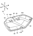
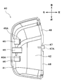
図5、図6に示すように、カバー部材40は、側方被覆部41と、下方被覆部42を有しており、カバー取付部30に取り付けられることで、天井部Rの下側部分に相当する送風流路部13の先端部を覆うように構成されている。
側方被覆部41は、カバー取付部30における側方部17を覆う部分であり、下方被覆部42は、カバー部材40の下部を構成し、カバー取付部30の下面18と共に、車両用空調装置1の下面を構成する部分である。
そして、カバー部材40は、側方被覆部41及び下方被覆部42を曲面で接続することによって、カバー取付部30の全体を覆うように構成されている。このように構成されたカバー部材40は、図5、図6に示すように、突出片45と、一対の上側係止爪46と、下側係止爪47と、下側規制片48とを有している。
突出片45は、カバー部材40の側方被覆部41を基準とした凹凸を為しており、側方被覆部41から水平方向に突出形成された角柱状の部分である。突出片45は、側方被覆部41から車両幅方向の内側(即ち、図5、図6の場合、左側方向)に向かって伸びている。そして、突出片45の断面積は、挿通開口35の開口面積に対して隙間嵌めの寸法関係になるように、挿通開口35の開口面積よりも小さく形成されている。
従って、突出片45は、カバー取付部30に対してカバー部材40を取り付ける際に、カバー取付部30における挿通開口35を挿通することができる。そして、突出片45は、カバー部材40の側方被覆部41から車両幅方向内側に向かって、水平に突出形成されている為、本開示における被嵌合部に相当する。
図5、図6に示すように、一対の上側係止爪46は、突出片45を挟むように配置されており、カバー部材40の側方被覆部41から水平方向に伸びている。換言すると、一対の上側係止爪46は、突出片45に対して車両前方側に位置する上側係止爪46と、突出片45に対して車両後方側に位置する上側係止爪46と、によって構成されている。
そして、各上側係止爪46の先端部には、爪部46Aが形成されている。爪部46Aは、上側係止爪46の先端部における上面側に形成されており、上方に向かって突出している。又、上側係止爪46における爪部46Aの上端部は、上側係合部36の下端よりも上方になるように形成されている。
従って、カバー取付部30に対してカバー部材40を取り付けた場合には、各上側係止爪46は、カバー取付部30における各上側係合部36に対して係合する。
図5、図6に示すように、カバー部材40における下方被覆部42の端部には、下側係止爪47と、下側規制片48が形成されている。下側規制片48は、下方被覆部42の端部に沿って形成された規制片であり、下方被覆部42の端部よりも上方に位置している。つまり、下側規制片48は、下方被覆部42の端部に対して段部を構成する。
これにより、カバー取付部30に対してカバー部材40を取り付けた場合に、下側規制片48は、下側係合部37の上面に対して上方から接触し、カバー取付部30に対するカバー部材40の下方への変位を規制することができる。
そして、下側係止爪47は、下方被覆部42の端部において、下側係合部37の係合突部37Aに対応する位置に形成されている。図5に示すように、下側係止爪47は、下側規制片48よりも上方から水平方向に伸びている。従って、カバー取付部30に対してカバー部材40を取り付けた場合に、下側係止爪47は、係合突部37Aに対して上方から接触する。
又、下側係止爪47の先端部には、爪部47Aが形成されている。爪部47Aは、下側係止爪47の先端部における下面側に形成されており、下方に向かって突出するように形成されている。そして、下側係止爪47における爪部47Aの下端は、係合突部37Aの上端よりも下方になるように形成されている。
従って、カバー取付部30に対してカバー部材40を取り付けた場合には、各下側係止爪47は、カバー取付部30における各下側係合部37の係合突部37Aに対して係合する。
続いて、上述のように構成されたカバー取付部30にカバー部材40を取り付けた際の各部の状態について、図7~図10を参照しつつ説明する。
尚、以下の説明においては、図4~図6におけるカバー取付部30やカバー部材40に関する説明と同様に、左右方向において右側に位置するカバー取付部30に対してカバー部材40を取り付けた状態について説明する。
この点、左右方向において左側に位置するカバー取付部30及びカバー部材40の状態について、その基本的な内容及び作用は、左右方向において右側に位置するカバー取付部30及びカバー部材40と同様である。従って、左右方向において左側に位置するカバー取付部30及びカバー部材40に関する説明は省略する。
上述したように、本実施形態に係る車両用空調装置1において、カバー取付部30に対してカバー部材40を取り付ける場合には、挿通開口35と突出片45の嵌合と、上側係合部36と上側係止爪46との係合と、下側係合部37と下側係止爪47との係合が行われる。
先ず、図8に示す断面について説明する。図8は、左右方向における右側のカバー取付部30に対してカバー部材40を取り付けた場合において、挿通開口35及び突出片45の状態を示す断面図である。本実施形態においては、カバー取付部30に対してカバー部材40を取り付ける場合には、カバー取付部30の挿通開口35に対して、カバー部材40の突出片45を挿通させる。
これにより、突出片45が伸びる方向の周りに、突出片45の開口縁が位置することになる為、突出片45の軸方向に鉛直な方向(即ち、車両における前後方向及び上下方向)への変位量は、挿通開口35の内側の範囲に抑制される。
ここで、カバー取付部30にカバー部材40が取り付けられた状態で衝撃が作用した場合、カバー部材40は、衝撃とカバー部材40の自重が作用することによって、挿通開口35の下側開口縁35Bと突出片45の接触部分を中心として、下方に向かって回動するような挙動を示す。
この時、挿通開口35の上側開口縁35Aと下側開口縁35Bが車両幅方向に同じ位置に位置していると、カバー部材40の回動に伴って、突出片45が挿通開口35を斜め下方から挿通する状態となることが考えられる。
車両用空調装置1が天井部Rに配置されている為、この状態になると、挿通開口35と突出片45との嵌合を解除する為に十分なスペースが車両用空調装置1の下方に確保されてしまう。又、この時、カバー部材40に作用する重力は、挿通開口35から突出片45を抜き出す為の力として作用してしまう。この為、下側開口縁35Bと突出片45の接触部分を中心としたカバー部材40の回動は、カバー部材40の脱落を高い確率で誘引するものと考えられる。
この点、図8に示すように、本実施形態に係る車両用空調装置1において、挿通開口35の下側開口縁35Bは、車両幅方向に関して、上側開口縁35Aよりも外側に位置している、従って、下側開口縁35Bと突出片45の接触部分を中心としたカバー部材40の回動しようとした場合であっても、上方へ変位しようとする突出片45の先端部分が、挿通開口35の上側開口縁35Aに接触することになり、水平な状態を維持することができる。
これにより、車両用空調装置1は、衝撃に伴って下側開口縁35Bと突出片45の接触部分を中心としてカバー部材40が回動することを抑制し、天井部Rに配置されたケース10からのカバー部材40の脱落を防止することができる。
図8に示すように、カバー部材40の下側規制片48は、カバー取付部30における下側係合部37の上面に接触するように配置されている。換言すると、カバー部材40の下部である下側規制片48は、下側係合部37によって下から支えられており、カバー部材40の下方への変位を抑制することができる。
そして、車両用空調装置1においては、挿通開口35と突出片45による嵌合構造と、下側係合部37と下側規制片48による支持構造は、カバー取付部30とカバー部材40の間において、車両上下方向及び車両幅方向に異なる位置に配置されており、それぞれ、カバー取付部30に対するカバー部材40の変位を規制している。
これにより、車両用空調装置1は、カバー取付部30に対するカバー部材40の変位を効率よく規制することができ、衝撃に伴ってカバー部材40が脱落することを防止することができる。
次に、図9に示す断面について説明する。図9は、左右方向における右側のカバー取付部30に対してカバー部材40を取り付けた場合において、係合突部37A及び下側係止爪47の状態を示す断面図である。図9に示すように、カバー部材40の下側係止爪47は、カバー取付部30における係合突部37Aに対して、係合突部37Aの上方から係合するように配置されている。この時、下側係止爪47の爪部47Aは、係合突部37Aの上端部に位置する隙間に進入して、係合突部37Aに係合する。
これにより、車両用空調装置1によれば、係合突部37Aと下側係止爪47によって、カバー取付部30及びカバー部材40の下部における位置関係を精度よく定めることができ、カバー部材40の下方及び車両幅方向への変位を抑制することができる。
又、下側係止爪47が爪部47Aを有している為、係合突部37Aと下側係止爪47の係合を解除する為には、カバー取付部30に対してカバー部材40を上方へ大きく変位させる必要が生じる。換言すると、爪部47Aがない場合と比較して、係合突部37Aと下側係止爪47の係合を強固にすることができ、カバー部材40の脱落を防止することができる。
又、図9においても、カバー部材40の下側規制片48は、カバー取付部30における下側係合部37の上面に接触するように配置されている。従って、車両用空調装置1によれば、係合突部37Aと下側係止爪47の係合に加えて、下側係合部37と下側規制片48による規制によって、カバー部材40の下方への変位を更に確実に抑制することができる。
続いて、図10に示す断面について説明する。図10は、左右方向における右側のカバー取付部30に対してカバー部材40を取り付けた場合において、上側係合部36及び上側係止爪46の状態を示す断面図である。図10に示すように、カバー取付部30に対してカバー部材40を取り付けた場合には、カバー部材40の上側係止爪46は、カバー取付部30の上側係合部36に対して、上側係合部36の下方から係合するように配置される。
これにより、車両用空調装置1によれば、上側係合部36と上側係止爪46によって、カバー取付部30及びカバー部材40の上部における位置関係を精度良く定めることができ、カバー部材40の上方への変位を抑制することができる。
又、上側係止爪46の先端には、爪部46Aが配置されており、爪部46Aの上端は、上側係合部36の下端よりも上方に位置した状態で係合している。従って、上側係合部36と上側係止爪46の係合を解除する為には、カバー取付部30に対してカバー部材40を上方へ大きく変位させる必要が生じる。
つまり、車両用空調装置1によれば、上側係合部36及び上側係止爪46の係合によって、カバー取付部30及びカバー部材40の上部における位置関係を精度よく定めることができ、カバー部材40の上方及び車両幅方向への変位を抑制することができる。
このように、車両用空調装置1によれば、挿通開口35と突出片45の嵌合と、上側係合部36と上側係止爪46の係合と、下側係合部37と下側係止爪47の係合によって、カバー取付部30における所定位置に、カバー部材40を精度よく取り付けることができる。
又、車両用空調装置1によれば、挿通開口35と突出片45の嵌合と、上側係合部36と上側係止爪46の係合と、下側係合部37と下側係止爪47の係合によって、衝撃に伴うカバー部材40の変位を抑制することができ、カバー部材40の脱落を防止することができる。
以上説明したように、本実施形態に係る車両用空調装置1は、車室Cの天井部Rにおいて、ケース10のファン収容部11内部に送風ファン20を有しており、各送風流路部13の先端部分に形成されたカバー取付部30に対して、それぞれカバー部材40が取り付けられている。
車両用空調装置1は、送風ファン20を作動させることで、ファン収容部11の吸込口12から車室C内の空気Aを吸いこみ、各送風流路部13及び各吹出口14を介して、車室Cに空気Aを供給することができる。即ち、車両用空調装置1は、天井配置型のサーキュレータとして機能し、車室Cにおける快適性を向上させることができる。
図8に示すように、ケース10のカバー取付部30に対してカバー部材40を取り付ける場合には、カバー取付部30の挿通開口35に対して、カバー部材40の突出片45を挿通させて嵌め合わせている。これにより、車両用空調装置1によれば、挿通開口35に対する突出片45の挿通によって、カバー取付部30に対するカバー部材40の変位を抑制して、衝撃に伴うカバー部材40の脱落を防止することができる。
又、カバー取付部30にカバー部材40を取り付けた場合、カバー部材40の下側係止爪47は、カバー取付部30の下側係合部37における係合突部37Aの上側から係合する。これにより、車両用空調装置1は、車両上下方向に関して、カバー取付部30に対するカバー部材40の変位を抑制することができ、衝撃によるカバー部材40の脱落を防止することができる。
図8~図10に示すように、車両用空調装置1によれば、挿通開口35と突出片45による嵌合と、下側係合部37と下側係止爪47による係合にて、カバー取付部30に対するカバー部材40の変位を異なる二カ所で規制することができる。これにより、車両用空調装置1は、車両用空調装置1に衝撃が加わった場合であっても、カバー取付部30に対するカバー部材40の変位を規制して、カバー部材40の脱落を抑制することができる。
図4~図6に示すように、カバー取付部30には、挿通開口35が形成されており、カバー部材40には、突出片45が形成されている。図8に示すように、カバー取付部30にカバー部材40を取り付ける場合には、挿通開口35には、突出片45が挿通される。このように、車両用空調装置1によれば、挿通開口35及び突出片45という比較的単純な形状を利用して、カバー部材40の脱落防止を実現できる。
又、挿通開口35に突出片45を挿通した場合、挿通開口35の開口縁は、突出片45を全周にわたって囲むように配置される。即ち、車両用空調装置1によれば、突出片45の伸びる方向に鉛直な全ての方向に関して、挿通開口35の開口縁との接触可能となる為、様々な方向に対するカバー部材40の変位を抑制することができる。
そして、図8に示すように、挿通開口35の下側開口縁35Bは、車両幅方向に関して、挿通開口35の上側開口縁35Aよりも外側に位置している。これにより、衝撃の作用によって、下側開口縁35Bと突出片45の接触点を中心としてカバー部材40が回動しようとした場合でも、上側開口縁35Aが突出片45の先端と接触して、カバー部材40の回動動作を規制することができ、カバー部材40の脱落を防止することができる。
図9に示すように、下側係止爪47は、その先端部分に下方に突出した爪部47Aを有しており、爪部47Aを用いて、係合突部37Aに上方から係合している。これにより、下側係合部37の係合突部37Aに対する下側係止爪47の係合を解除する為に必要な変位量が増大することになる為、カバー取付部30からのカバー部材40の脱落を防止することができる。
図4~図6に示すように、カバー取付部30には、上側係合部36が形成されており、カバー部材40には、上側係止爪46が形成されている。そして、車両用空調装置1によれば、上側係合部36と上側係止爪46の係合によって、カバー取付部30及びカバー部材40の上部にて、車両上下方向に関するカバー部材40の変位を抑制することができ、衝撃によるカバー部材40の脱落を防止することができる。
又、車両用空調装置1によれば、挿通開口35と突出片45の嵌合と、下側係合部37と下側係止爪47の係合に加えて、上側係合部36及び上側係止爪46による係合を協働させることができる。これにより、車両用空調装置1は、カバー取付部30に対するカバー部材40の変位を更に抑えて、衝撃によるカバー部材40の脱落を防止することができる。
そして、下側係合部37と下側係止爪47の係合を解除する為のカバー部材40の変位方向(即ち、車両上側方向)は、上側係合部36と上側係止爪46の係合を強める方向になる。この為、車両用空調装置1は、上側係合部36と上側係止爪46を採用することで、カバー部材40の脱落を抑制することができる。
図10に示すように、上側係止爪46の先端部分には、上方に突出した爪部46Aが形成されている。車両用空調装置1においては、上側係止爪46に爪部46Aを形成することによって、上側係合部36と上側係止爪46の係合を解除する為に必要な変位量を増大させることができる。即ち、車両用空調装置1は、上側係合部36と上側係止爪46の係合を強固にすることで、カバー部材40の脱落を防止することができる。
(他の実施形態)
本開示は上述した実施形態に何ら限定されるものではない。即ち、本開示の趣旨を逸脱しない範囲内で種々の改良変更が可能である。例えば、上述した各実施形態を適宜組み合わせても良いし、上述した実施形態を種々変形することも可能である。
本開示は上述した実施形態に何ら限定されるものではない。即ち、本開示の趣旨を逸脱しない範囲内で種々の改良変更が可能である。例えば、上述した各実施形態を適宜組み合わせても良いし、上述した実施形態を種々変形することも可能である。
(1)上述した実施形態においては、本開示に係る車両用空調装置として、天井設置型のサーキュレータを用いていたが、この態様に限定されるものではない。本開示に係る車両用空調装置は、車室の天井に配置され、且つ、車室内を空調することができれば、種々の態様を採用することができる。例えば、車両用空調装置1として、ケース10内に、送風ファンと共に蒸気圧縮式の冷凍サイクルを収容し、冷凍サイクルを用いて温度調整が施された空調空気を車室内に供給するように構成してもよい。
(2)又、上述した実施形態においては、本開示に係る嵌合部として、カバー取付部30に挿通開口35を形成し、本開示に係る被嵌合部として、カバー部材40に突出片45を形成した態様であったが、この態様に限定されるものではない。ケース側であるカバー取付部30に突出片のような凸部を形成し、カバー部材40側に挿通開口のような凹部を形成してもよい。
(3)そして、上述した実施形態においては、図4、図8に示すように、挿通開口35は、カバー取付部30における板状部を貫通するように構成されていたが、この態様に限定するものではない。本開示における挿通開口や嵌合部としては、突出片45のような凸部が嵌合可能に構成された窪みを用いてもよい。
Claims (6)
- 車室(C)に対する空気の流れを発生させる送風機(20)と、
前記車室の天井部(R)に対して下面(18)及び側方部(17)の一部分が車室に露出するように配置され、前記送風機を内部に収容するケース(10)と、
前記車室に露出した前記ケースの下面の一部分及び側方部の一部分を含む外縁部(30)に対して取り付けられ、前記外縁部を覆うカバー部材(40)を有し、
前記ケースは、
前記外縁部における側方部に形成され、水平方向に対して凹凸を為す嵌合部(35)と、
前記外縁部における下面に形成された下側係合部(37)を有し、
前記カバー部材は、
前記外縁部における側方部を覆う側方被覆部(41)において、前記水平方向に対して凹凸を為すように形成され、前記嵌合部と嵌合する被嵌合部(45)と、
前記カバー部材の下部に形成され、前記下側係合部の上方にて前記下側係合部と係合する下側係止爪(47)とを有する車両用空調装置。 - 前記嵌合部は、前記外縁部における側方部にて、前記水平方向に凹むように形成された挿通開口(35)であり、
前記被嵌合部は、前記側方被覆部において、前記水平方向に突出するように形成され、前記挿通開口を挿通する突出片(45)である請求項1に記載の車両用空調装置。 - 前記挿通開口における下側開口縁(35B)は、前記ケースにおける前記水平方向に関して、前記挿通開口における上側開口縁(35A)よりも、前記ケースの外側に位置している請求項2に記載の車両用空調装置。
- 前記下側係止爪は、下方に突出し前記下側係合部と係合する爪部(47A)を有している請求項1ないし3の何れか1つに記載の車両用空調装置。
- 前記ケースは、前記外縁部における側方部に形成された上側係合部(36)を有し、
前記カバー部材は、前記側方被覆部から前記水平方向に突出するように形成され、前記上側係合部の下方にて前記上側係合部と係合する上側係止爪(46)を有する請求項1ないし4の何れか1つに記載の車両用空調装置。 - 前記上側係止爪は、上方に突出し前記上側係合部と係合する爪部(46A)を有している請求項5に記載の車両用空調装置。
Applications Claiming Priority (2)
| Application Number | Priority Date | Filing Date | Title |
|---|---|---|---|
| JP2017-148192 | 2017-07-31 | ||
| JP2017148192A JP6794955B2 (ja) | 2017-07-31 | 2017-07-31 | 車両用空調装置 |
Publications (1)
| Publication Number | Publication Date |
|---|---|
| WO2019026480A1 true WO2019026480A1 (ja) | 2019-02-07 |
Family
ID=65233969
Family Applications (1)
| Application Number | Title | Priority Date | Filing Date |
|---|---|---|---|
| PCT/JP2018/024483 Ceased WO2019026480A1 (ja) | 2017-07-31 | 2018-06-28 | 車両用空調装置 |
Country Status (2)
| Country | Link |
|---|---|
| JP (1) | JP6794955B2 (ja) |
| WO (1) | WO2019026480A1 (ja) |
Cited By (1)
| Publication number | Priority date | Publication date | Assignee | Title |
|---|---|---|---|---|
| WO2020244828A1 (de) * | 2019-06-04 | 2020-12-10 | Bayerische Motoren Werke Aktiengesellschaft | Kraftfahrzeug |
Citations (7)
| Publication number | Priority date | Publication date | Assignee | Title |
|---|---|---|---|---|
| JPS60151113A (ja) * | 1984-01-20 | 1985-08-09 | Hitachi Ltd | 自動車用空調機 |
| JPH0948230A (ja) * | 1995-08-10 | 1997-02-18 | Mitsubishi Heavy Ind Ltd | 車両用天井設置型空気調和機 |
| JPH1016536A (ja) * | 1996-07-02 | 1998-01-20 | Yazaki Corp | ルーフエアコン組立体 |
| JP2000289430A (ja) * | 1999-04-08 | 2000-10-17 | Mitsubishi Heavy Ind Ltd | オーバーヘッド型車両用空調ユニット |
| JP2002098376A (ja) * | 2000-09-26 | 2002-04-05 | Toyoda Gosei Co Ltd | 空気清浄機 |
| JP2005199862A (ja) * | 2004-01-15 | 2005-07-28 | Nippon Soken Inc | 車両用オーバヘッドモジュール |
| JP2014139066A (ja) * | 2012-12-20 | 2014-07-31 | Denso Corp | 車両用送風装置 |
Family Cites Families (1)
| Publication number | Priority date | Publication date | Assignee | Title |
|---|---|---|---|---|
| JP2014019270A (ja) * | 2012-07-17 | 2014-02-03 | Toyota Motor Corp | 車両用空調装置 |
-
2017
- 2017-07-31 JP JP2017148192A patent/JP6794955B2/ja active Active
-
2018
- 2018-06-28 WO PCT/JP2018/024483 patent/WO2019026480A1/ja not_active Ceased
Patent Citations (7)
| Publication number | Priority date | Publication date | Assignee | Title |
|---|---|---|---|---|
| JPS60151113A (ja) * | 1984-01-20 | 1985-08-09 | Hitachi Ltd | 自動車用空調機 |
| JPH0948230A (ja) * | 1995-08-10 | 1997-02-18 | Mitsubishi Heavy Ind Ltd | 車両用天井設置型空気調和機 |
| JPH1016536A (ja) * | 1996-07-02 | 1998-01-20 | Yazaki Corp | ルーフエアコン組立体 |
| JP2000289430A (ja) * | 1999-04-08 | 2000-10-17 | Mitsubishi Heavy Ind Ltd | オーバーヘッド型車両用空調ユニット |
| JP2002098376A (ja) * | 2000-09-26 | 2002-04-05 | Toyoda Gosei Co Ltd | 空気清浄機 |
| JP2005199862A (ja) * | 2004-01-15 | 2005-07-28 | Nippon Soken Inc | 車両用オーバヘッドモジュール |
| JP2014139066A (ja) * | 2012-12-20 | 2014-07-31 | Denso Corp | 車両用送風装置 |
Cited By (2)
| Publication number | Priority date | Publication date | Assignee | Title |
|---|---|---|---|---|
| WO2020244828A1 (de) * | 2019-06-04 | 2020-12-10 | Bayerische Motoren Werke Aktiengesellschaft | Kraftfahrzeug |
| CN113825660A (zh) * | 2019-06-04 | 2021-12-21 | 宝马股份公司 | 机动车 |
Also Published As
| Publication number | Publication date |
|---|---|
| JP6794955B2 (ja) | 2020-12-02 |
| JP2019026112A (ja) | 2019-02-21 |
Similar Documents
| Publication | Publication Date | Title |
|---|---|---|
| US11987157B2 (en) | Vehicle seat | |
| US20140256244A1 (en) | Air conditioning device for vehicle | |
| CN108372770B (zh) | 用于控制车辆的细长型通气孔中空气流动方向的装置 | |
| CN104755292A (zh) | 车辆用空气循环促进装置 | |
| WO2016158472A1 (ja) | 車両用シート空調ユニット | |
| CN113246823A (zh) | 座椅靠背的通风结构 | |
| CN105599582A (zh) | 车辆 | |
| WO2019026480A1 (ja) | 車両用空調装置 | |
| JP6883452B2 (ja) | 車両用空気吹出装置 | |
| US20110014860A1 (en) | Front foot air vent for automobile | |
| JP5493630B2 (ja) | 車両用シート空調装置 | |
| US10639958B2 (en) | Air conditioning device | |
| JP6641552B2 (ja) | 乗物用シート | |
| JP6662214B2 (ja) | 乗物用シートの送風装置 | |
| JP7047663B2 (ja) | 車両用空調装置 | |
| KR20190058817A (ko) | 차량용 공조장치 | |
| WO2021137296A1 (ja) | 車両用空調装置 | |
| JP2021123275A (ja) | 車両用空調装置 | |
| US20250332971A1 (en) | Blower mounting structure for vehicle seat and vehicle seat | |
| JP3873810B2 (ja) | 車両用ダクト構造 | |
| JP7286390B2 (ja) | 車両用の空気吹き出し装置 | |
| JPS623289Y2 (ja) | ||
| JP6547684B2 (ja) | 車載用サーキュレータ | |
| JPS6220333Y2 (ja) | ||
| JP2012111324A (ja) | 自動車用ベンチレータ |
Legal Events
| Date | Code | Title | Description |
|---|---|---|---|
| 121 | Ep: the epo has been informed by wipo that ep was designated in this application |
Ref document number: 18840450 Country of ref document: EP Kind code of ref document: A1 |
|
| NENP | Non-entry into the national phase |
Ref country code: DE |
|
| 122 | Ep: pct application non-entry in european phase |
Ref document number: 18840450 Country of ref document: EP Kind code of ref document: A1 |