WO2019021360A1 - Refrigeration cycle device - Google Patents
Refrigeration cycle device Download PDFInfo
- Publication number
- WO2019021360A1 WO2019021360A1 PCT/JP2017/026787 JP2017026787W WO2019021360A1 WO 2019021360 A1 WO2019021360 A1 WO 2019021360A1 JP 2017026787 W JP2017026787 W JP 2017026787W WO 2019021360 A1 WO2019021360 A1 WO 2019021360A1
- Authority
- WO
- WIPO (PCT)
- Prior art keywords
- oil
- oil return
- return circuit
- refrigeration cycle
- scroll compressor
- Prior art date
Links
Images


Classifications
-
- F—MECHANICAL ENGINEERING; LIGHTING; HEATING; WEAPONS; BLASTING
- F25—REFRIGERATION OR COOLING; COMBINED HEATING AND REFRIGERATION SYSTEMS; HEAT PUMP SYSTEMS; MANUFACTURE OR STORAGE OF ICE; LIQUEFACTION SOLIDIFICATION OF GASES
- F25B—REFRIGERATION MACHINES, PLANTS OR SYSTEMS; COMBINED HEATING AND REFRIGERATION SYSTEMS; HEAT PUMP SYSTEMS
- F25B1/00—Compression machines, plants or systems with non-reversible cycle
- F25B1/04—Compression machines, plants or systems with non-reversible cycle with compressor of rotary type
Definitions
- the present invention relates to a refrigeration cycle apparatus provided with a scroll compressor.
- the scroll compressor constituting the refrigeration cycle apparatus transmits the rotational force of the electric mechanism and the electric mechanism to the compression mechanism, which compresses the refrigerant in the compression chamber formed by combining the fixed scroll and the oscillating scroll.
- a rotating shaft is provided in the container.
- oil is mixed in the refrigerant in order to lubricate sliding parts such as the bearing of the rotary shaft or to seal an appropriate part of the compression mechanism, and the refrigerant mixed with oil is It circulates in the piping of the refrigeration cycle device.
- the oil in the compression mechanism may be diluted with the liquid refrigerant by injecting the liquid refrigerant into the compression mechanism, and the sealability of the compression mechanism may be deteriorated.
- the oil separated in the oil separator is returned to the scroll compressor, and the oil return circuit is branched into two, one returns the oil to the oil reservoir as described above, and the other feeds the injection pipe.
- the liquid refrigerant is mixed with the liquid refrigerant in the injection pipe and supplied to the compression mechanism.
- Patent Document 1 As described above, the oil separated by the oil separator is divided back into the oil reservoir and the compression mechanism, but the oil returned to the compression mechanism is compressed by the compression mechanism. It tends to flow out of the scroll compressor together with the refrigerant. For this reason, the amount of oil flowing out from the compression mechanism increases particularly at high speed operation, and the oil in the oil reservoir is depleted, causing insufficient oil supply at sliding parts such as bearings, and a problem of the reliability of the scroll compressor being lowered. There is.
- the present invention has been made in view of such a point, and an object of the present invention is to provide a refrigeration cycle apparatus capable of suppressing oil outflow to the outside of the compressor during high speed operation.
- the refrigeration cycle apparatus includes a scroll compressor, a condenser, a pressure reducing device, and an evaporator, and is branched from between a main circuit in which a refrigerant containing oil circulates, and between the condenser and the pressure reducing device. And an oil separator provided in the main circuit to separate oil from the refrigerant discharged from the scroll compressor, and oil returned by the oil separator being returned to the scroll compressor.
- the scroll compressor includes a container whose bottom is an oil reservoir, a motorized mechanism housed in the container, and a compressor which is housed in the container and formed by combining a swing scroll and a fixed scroll.
- the compression mechanism that compresses the refrigerant in the chamber, the motor-driven mechanism and the compression mechanism are connected, and the rotary shaft that transmits the rotational force of the motor-driven mechanism to the compression mechanism Through the flow path
- the oil return circuit is bifurcated on the downstream side with the outlet of one of the first oil return circuits communicating with the displacement pump and the other second oil return circuit.
- the outlet of the valve is in communication with the injection circuit.
- the downstream side of the oil return circuit for returning the oil separated by the oil separator to the scroll compressor is bifurcated, and the outlet of one of the first oil return circuits is communicated with the positive displacement pump, The outlet of the second oil return circuit is connected to the injection circuit.
- the first oil return circuit that directly returns the oil separated by the oil separator to the positive displacement pump instead of the oil reservoir the first oil return circuit from the oil separator is operated at high speed. It is possible to relatively increase the amount of oil returned to the in-axis flow passage of the rotating shaft via the rotation shaft as compared with the low speed operation. As a result, it is possible to suppress oil outflow to the outside of the compressor during high speed operation.
- FIG. 1 is a refrigerant circuit diagram of a refrigeration cycle apparatus according to Embodiment 1 of the present invention. It is a schematic longitudinal cross-sectional view of the whole structure of the scroll compressor which comprises the refrigerating-cycle apparatus which concerns on Embodiment 2 of this invention.
- FIG. 4 is a schematic horizontal sectional view of the compression mechanism of FIG. 3; It is a schematic longitudinal cross-sectional view of the whole structure of the scroll compressor which comprises the refrigerating-cycle apparatus which concerns on Embodiment 3 of this invention.
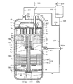
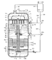
- FIG. 1 is a schematic vertical cross-sectional view of the overall configuration of a scroll compressor that constitutes a refrigeration cycle apparatus according to Embodiment 1 of the present invention.
- Arrows in FIG. 1 indicate flows of refrigerant and oil. The same applies to the figures described later.
- the scroll compressor 100 has a compression mechanism 3, an electric mechanism 110, and other components.
- the scroll compressor 100 has a configuration in which these components are housed inside a container 100a constituting an outer shell.
- the compression mechanism 3 and the motor-driven mechanism 110 are connected via the rotary shaft 6, and the rotational force generated by the motor-driven mechanism 110 is transmitted to the compression mechanism 3 via the rotary shaft 6.
- the refrigerant is adapted to be compressed.
- the container 100a is provided with a suction pipe 101 for suctioning the refrigerant, a discharge pipe 102 for discharging the refrigerant, and an injection pipe 103 for suctioning an injection refrigerant described later into the compression mechanism 3 .
- the injection pipe 103 is for introducing a refrigerant into the compression mechanism 3 in the container 100 a separately from the suction pipe 101.
- the injection pipe 103 is connected to an injection port 7 a formed in a frame 7 described later.
- a frame 7 and a sub-frame 9 for fixing the compression mechanism 3 to the container 100a are disposed inside the container 100a.
- the frame 7 is disposed on the upper side of the electromotive mechanism 110 and on the lower side of the compression mechanism 3 and is fixed to the inner circumferential surface of the container 100a by shrink fitting, welding or the like.
- a communication channel 7 c for guiding the refrigerant flowing from the suction pipe 101 into the compression mechanism 3 is formed in the frame 7.
- the sub-frame 9 is disposed below the motor-driven mechanism 110, and is fixed to the inner circumferential surface of the container 100a by shrink fitting, welding or the like via the sub-frame plate 9a.
- a displacement pump 111 is attached to the lower end of the sub-frame 9 so as to axially support the rotary shaft 6 at the upper end face.
- the rotation shaft 6 is provided with an in-shaft flow passage 6 d.
- the in-shaft flow path 6d has an oil hole 6da axially extending in the central portion of the rotary shaft 6, and a plurality of oil supply holes 6db communicating radially with the oil hole 6da.
- the oil supply hole 6db is formed at a position facing each of the rocking bearing 2c, the main bearing 7b, and the auxiliary bearing 10, and is a sliding portion of the rotating shaft 6, and supplied from the positive displacement pump 111 to each of these bearings.
- To supply the The oil supplied to the rocking bearing 2c and the like is returned from the bearing operation space 73 described later through the oil return pipe 113 to the oil reservoir 100b.
- One end of the suction pipe 111a is connected to the positive displacement pump 111, and the other end of the suction pipe 111a is immersed in the oil reservoir 100b to suck up the oil in the oil reservoir 100b to flow the inner flow passage 6d of the rotating shaft 6 Supply to
- the compression mechanism 3 has a fixed scroll 1 and an oscillating scroll 2.
- the fixed scroll 1 is fixed to the frame 7.
- the swing scroll 2 is disposed below the fixed scroll 1 and swingably supported by an eccentric shaft portion 6 a described later of the rotation shaft 6.
- the fixed scroll 1 has a fixed base plate 1a and a fixed scroll 1b provided upright on one surface of the fixed base plate 1a.
- the rocking scroll 2 has a rocking bed plate 2a and a rocking scroll 2b provided upright on one surface of the rocking bed plate 2a.
- the fixed scroll 1 and the rocking scroll 2 are disposed in the container 100 a in a symmetrical spiral shape in which the fixed scroll 1 b and the rocking scroll 2 b are meshed in the reverse phase with respect to the rotation center of the rotating shaft 6 There is.
- a compression chamber 8 is formed between the fixed scroll 1b and the swinging scroll 2b, the volume of which decreases as it goes from the radially outer side to the inner side as the rotary shaft 6 rotates.
- a structure portion having a symmetrical spiral shape in which the rocking scroll 2b and the fixed scroll 1b are combined in particular is referred to as a spiral portion 3a.
- a discharge port 1c communicating with the compression chamber 8 is formed through the fixed base plate 1a of the fixed scroll 1 and a discharge valve 11 is provided in the discharge port 1c. And the discharge muffler 12 is attached so that this discharge port 1c may be covered.
- a cylindrical boss 2d is formed substantially at the center of the surface (hereinafter referred to as the back surface) opposite to the surface on which the rocking scroll 2b is formed in the rocking base plate 2a of the rocking scroll 2.
- a rocking bearing 2c is disposed inside the boss 2d, and an eccentric shaft 6a formed on the upper end of the rotary shaft 6 is fitted inside the rocking bearing 2c.
- the rotating shaft 6 is composed of an eccentric shaft 6 a at the upper part of the rotating shaft 6, a main shaft 6 b, and a sub shaft 6 c at the lower part of the rotating shaft 6.
- the eccentric shaft 6a is rotatably fitted to the boss 2d of the rocking scroll 2 via the rocking bearing 2c, and slides on the rocking bearing 2c via an oil film of oil.
- the rocking bearing 2c is fixed in the boss portion 2d by press-fitting a bearing material such as a copper-lead alloy used for a sliding bearing.
- the rocking scroll 2 is rocked by the rotation of the rotary shaft 6.
- the main shaft portion 6b is rotatably fitted to the main bearing 7b provided on the frame 7, and slides with the main bearing 7b via an oil film of oil.
- the main bearing 7b is fixed to the frame 7 by press-fitting or the like of a bearing material such as a copper-lead alloy used for a slide bearing.
- the central portion of the sub-frame 9 is provided with a sub bearing 10 composed of a ball bearing, and supports the rotating shaft 6 in the radial direction below the electric mechanism 110.
- the auxiliary bearing 10 may have another bearing configuration other than the ball bearing.
- the countershaft 6 c of the rotating shaft 6 is fitted to the subbearing 10 and slides on the subbearing 10.
- the axial centers of the main shaft portion 6 b and the auxiliary shaft portion 6 c coincide with the axial center of the rotation shaft 6.
- the space in the container 100a is defined as follows. Of the internal space of the container 100a, it is formed by the inner wall of the recess formed on the upper surface of the frame 7 and the outermost peripheral surface of the structure portion in which the swinging scroll 2b of the compression mechanism 3 and the fixed scroll 1b are engaged. This space is called a spiral installation space 70. Further, the space below the frame 7 in the internal space of the container 100 a is referred to as a shell suction space 71.
- the shell suction space 71 is a low pressure space filled with the suction refrigerant introduced from the suction pipe 101.
- a shell discharge space 72 the space on the discharge pipe 102 side from the fixed base plate 1 a of the compression mechanism 3 is referred to as a shell discharge space 72.
- a space formed in the frame 7 for accommodating the rocking bearing 2c and rotating the rocking bearing 2c is referred to as a bearing operation space 73.
- an inner space between the upper end of the rotary shaft 6 and the swing base plate 2 a of the swing scroll 2 and an inner space of the boss 2 d is referred to as a boss inner space 74.
- the electromotive mechanism 110 has a motor stator 110a and a motor rotor 110b.
- the motor stator 110a is connected by a lead wire (not shown) to a glass terminal (not shown) present between the frame 7 and the motor stator 110a in order to obtain power from the outside.
- the motor rotor 110 b is fixed to the rotating shaft 6 by shrink fitting or the like. Further, in order to balance the entire rotation system of the scroll compressor 100, the first balance weight 60 is fixed to the rotation shaft 6, and the second balance weight 61 is fixed to the motor rotor 110b. There is.
- oil flows from the suction pipe 101 together with the refrigerant.
- the oil is used for the purpose of improving the lubricity of the sliding portion and the sealing function for suppressing the gap leak of the compression chamber 8.
- An oil separator 202 is disposed downstream of the scroll compressor 100 to separate oil from the refrigerant discharged from the scroll compressor 100.
- a refrigeration cycle apparatus 300 including the scroll compressor 100 and the oil separator 202 will be described.
- FIG. 2 is a refrigerant circuit diagram of the refrigeration cycle apparatus according to Embodiment 1 of the present invention.
- a scroll compressor 100 In the refrigeration cycle apparatus 300, a scroll compressor 100, an oil separator 202, a condenser 301, a decompression device 302 including an expansion valve or a capillary tube, and an evaporator 303 are sequentially connected by refrigerant piping.
- a main circuit 300a through which the refrigerant circulates is provided.
- the refrigeration cycle apparatus 300 further includes an injection circuit 305 separated from between the condenser 301 and the pressure reducing device 302 and connected to the injection pipe 103 of the scroll compressor 100.
- the injection circuit 305 is provided with an expansion valve 304 as a flow rate adjustment valve, so that the flow rate to be injected can be adjusted.
- the oil separator 202 is connected to the discharge pipe 102 of the scroll compressor 100 by a circuit 201.
- the opening degree of the pressure reducing device 302, the opening degree of the expansion valve 304, and the rotation speed of the scroll compressor 100 are controlled by a control device (not shown).
- a four-way valve may be further provided in the refrigeration cycle apparatus 300 to switch the flow direction of the refrigerant in the reverse direction.
- the condenser 301 installed downstream of the scroll compressor 100 is the indoor unit side and the evaporator 303 is the outdoor unit side
- the heating operation is performed
- the condenser 301 is the outdoor unit side and the evaporator 303 is the indoor unit side. If it does, it will be cooling operation.
- the oil in the oil separator 202 is returned to the scroll compressor 100 into two branches downstream of the oil return circuit 206, and the outlet of one oil return circuit 204 is the container 100a.
- This configuration is in direct communication with the positive displacement pump 111 instead of the oil reservoir 100 b at the bottom.
- the outlet of the other oil return circuit 205 is in communication with the injection circuit 305.
- the oil returned from the oil return circuit 204 mainly lubricates the bearings, and the oil returned from the oil return circuit 205 improves the sealability of the compression mechanism 3.
- the oil return circuit 204 corresponds to a first oil return circuit of the present invention
- the oil return circuit 205 corresponds to a second oil return circuit of the present invention.
- a pipe constituting the oil return circuit 204 is extended upstream of a branch point with the oil return circuit 205 and connected to the bottom of the oil separator 202. . Further, the downstream end of the pipe constituting the oil return circuit 204 is configured to penetrate the container 100 a and be connected to the suction port of the positive displacement pump 111. As a specific configuration of the oil return circuit 205, the upstream end of the pipe constituting the oil return circuit 205 is connected to the pipe of the oil return circuit 204, and the downstream end is connected to the pipe of the injection circuit 305.
- a pump chamber (not shown) in the positive displacement pump 111 is first connected to the low pressure suction pipe 111a, and its volume is expanded as it rotates to suck oil from the suction pipe 111a, and then the suction pipe 111a Close the connection with Next, the pump chamber (not shown) is connected to the high pressure oil return circuit 204 piping, and the volume is further expanded to suck in the oil of the oil return circuit 204, and then the connection with the oil return circuit 204 piping close up.
- the pump chamber (not shown) is connected to the in-shaft channel 6d, and the volume is reduced, and the sucked oil is discharged to the in-shaft channel 6d to close the connection with the in-shaft channel 6d and return first.
- the positive displacement pump 111 a positive displacement pump configured to operate in this manner can be used.
- the refrigerant discharged from the scroll compressor 100 flows into the oil separator 202.
- the refrigerant and the oil mixed in the refrigerant are separated, and the separated refrigerant is cooled by the condenser 301.
- the refrigerant cooled by the condenser 301 is reduced in pressure by the pressure reducing device 302 and then heated by the evaporator 303 to become a refrigerant gas.
- the refrigerant gas flowing out of the evaporator 303 returns to the scroll compressor 100.
- the refrigerant returning to the scroll compressor 100 flows into the container 100 a from the suction pipe 101.
- the low-pressure refrigerant flowing from the suction pipe 101 into the shell suction space 71 in the container 100 a passes through the communication flow path 7 c formed in the frame 7 and flows into the spiral installation space 70.
- the refrigerant flowing into the swirl installation space 70 mixes with the refrigerant flowing from the injection pipe 103 via the injection port 7 a. Then, the mixed refrigerant is drawn into the compression chamber 8 along with the relative swing operation of the fixed scroll 1 b of the fixed scroll 1 and the swing scroll 2 b of the swing scroll 2.
- the sucked refrigerant is boosted from low pressure to high pressure by the geometric volume change of the compression chamber 8 accompanying the operation of the oscillating scroll 2.
- the discharge valve 11 is opened, and the refrigerant is discharged to the shell discharge space 72 from the discharge port 1c installed in the fixed scroll 1. . Thereafter, the discharged refrigerant is discharged from the discharge pipe 102 via the shell discharge space 72 as a high pressure refrigerant to the circuit 201 outside the compressor.
- the refrigerant of the circuit 201 discharged from the scroll compressor flows into the oil separator 202, separates the oil contained in the refrigerant, and then flows out to the circuit 203 directed to the condenser 301.
- part of the refrigerant cooled by the condenser 301 flows into the injection circuit 305, and flows through the expansion valve 304 into the injection pipe 103 of the scroll compressor 100.
- the liquid or two-phase injection refrigerant flowing into the injection pipe 103 passes through the swirl installation space 70 and flows into the suction chamber in the compression mechanism 3.
- the oil that has flowed out of the scroll compressor 100 is separated by the oil separator 202, passes through the oil return circuit 206, and is supplied to the scroll compressor 100.
- the oil return circuit 206 the oil return circuit 204 is connected to the suction port of the positive displacement pump 111. Therefore, the oil stored in the oil separator 202 is supplied from the suction port of the positive displacement pump 111 to the in-shaft flow path 6 d of the rotating shaft 6. Then, the oil supplied to the in-shaft flow path 6d is supplied to the sliding portions such as the rocking bearing 2c, the main bearing 7b, and the sub bearing 10.
- a portion of the oil supplied to the sliding portion is supplied to a bearing operation space 73 installed downstream of the rocking bearing 2c and the main bearing 7b. Thereafter, the oil supplied to the bearing operation space 73 is stored in the oil reservoir 100b of the container 100a through the oil return pipe 113. Part of the oil stored in the oil reservoir 100b is sucked from the suction pipe 111a by the operation of the positive displacement pump 111 by the rotation of the rotary shaft 6, and is supplied again to the sliding portion. Further, a part of the oil stored in the oil reservoir 100b is wound up by the flow of the refrigerant flowing from the suction pipe 101, flows into the compression mechanism 3 through the communication flow path 7c, and then to the outside of the scroll compressor 100. And flow out.
- the downstream side of the oil return circuit 205 is connected to the injection circuit 305. Therefore, the oil stored in the oil separator 202 is supplied from the oil return circuit 205 to the injection refrigerant of the injection circuit 305 and flows into the spiral installation space 70 of the compression mechanism 3 together with the injection refrigerant. The oil that has flowed into the swirl installation space 70 flows into the compression chamber 8 and flows out of the scroll compressor 100.
- the positive displacement pump 111 is configured such that the oil return circuit 206 from the oil separator 202 is branched into two, and one oil return circuit 204 is configured by the positive displacement pump instead of the oil reservoir 100 b. , And the other oil return circuit 205 is in communication with the injection circuit 305. Since the displacement pump also increases the discharge amount of oil as the rotational speed increases, the amount of oil returned from the oil separator 202 to the in-shaft flow path 6d via the oil return circuit 204 during the high speed operation is a low speed It can be relatively increased compared to when driving.
- the sealability of the compression mechanism 3 can be improved by positively returning oil from the oil separator 202 to the injection circuit 305.
- the second embodiment relates to a configuration in which the connection position of the injection pipe 103 is changed in the first embodiment shown in FIG.
- the second embodiment will be described focusing on the difference from the first embodiment.
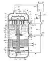
- FIG. 3 is a schematic vertical cross-sectional view of the entire configuration of a scroll compressor that constitutes a refrigeration cycle apparatus according to Embodiment 2 of the present invention.
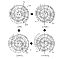
- FIG. 4 is a horizontal schematic cross-sectional view of the compression mechanism of FIG.
- the phases of 0 deg, 90 deg, 180 deg and 270 deg described in FIG. 4 indicate the rotational phase of the compression mechanism.
- the injection pipe 103 penetrates the container 100a from the outside and is inserted into the inside, and is connected to the injection port 207 formed in the fixed base plate 1a.
- the outlet 103a of the injection pipe 103 is communicated with the inside of the compression mechanism 3, and the injection refrigerant flows into the compression chamber 8 in the middle of the compression process, in other words, the intermediate pressure space 75 where the inside is an intermediate pressure.
- the intermediate pressure refers to the pressure between the suction pressure and the discharge pressure.
- the amount of oil flowing from the oil separator 202 to the injection pipe 103 can be suppressed as compared with the first embodiment.
- the pressure difference with the outlet 103a of the Therefore, even if the injection refrigerant flow rate is equal, the amount of oil flowing from the oil separator 202 to the injection pipe 103 can be suppressed.
- the second embodiment compared to the first embodiment, it is possible to suppress the excessive oil supply from the injection pipe 103 to the compression mechanism 3 even under the operating condition where the high / low pressure difference is large and reduce the oil outflow. It becomes. Therefore, it is possible to provide a scroll compressor having high performance and reliability in a wide operating range.
- a resistance element is further provided to the configuration of the first embodiment shown in FIG.
- the configuration in which the third embodiment is different from the first embodiment will be mainly described.
- FIG. 5 is a schematic vertical cross-sectional view of the overall configuration of a scroll compressor that constitutes a refrigeration cycle apparatus according to a third embodiment of the present invention.
- the third embodiment has a configuration in which a capillary tube 210 is installed as a resistance element on the downstream side of the connection portion 205 a with the oil return circuit 205 in the injection circuit 305.
- the capillary tube 210 reduces the flow rate of the injection refrigerant flowing from the injection circuit 305 into the compression mechanism 3.
- the same effect as that of the first embodiment can be obtained, and the following effect can be obtained by disposing the capillary tube 210 downstream of the connection portion 205a with the oil return circuit 205 in the injection circuit 305. . That is, the flow rate of the injection refrigerant flowing into the scroll compressor 100 can be reduced after the installation as compared to before the installation of the capillary tube 210. For this reason, as in the case of the second embodiment, it is possible to suppress excessive refueling to the compression mechanism 3.
- the resistance element is constituted by the capillary tube 210
- the flow velocity is increased in the capillary tube 210, so that the refrigerant passing through the injection circuit 305 and the oil flowing from the oil return circuit 205 into the injection circuit 305 are convectively stirred. it can. Therefore, the refrigerant and the oil can be mixed in a more uniform mixed state and then supplied to the spiral portion 3 a of the compression mechanism 3.
- the sealability of the compression mechanism 3 can be further improved as compared with the first and second embodiments. Therefore, the third embodiment can provide the scroll compressor 100 having higher performance than the first embodiment and the second embodiment.
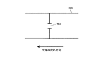
- capillary tube 210 was mentioned as an example and demonstrated as a resistance element here, you may use fixed resistance like the strainer 217 as shown, for example in FIG. 6 or the orifice hole 218 as shown in FIG. . Further, as shown in FIG. 8 below, a variable resistor such as a flow rate adjustment valve may be used.
- FIG. 8 is a schematic vertical cross-sectional view of the entire configuration of a modification of the scroll compressor that constitutes the refrigeration cycle apparatus according to Embodiment 3 of the present invention.
- a flow rate adjusting valve 211 configured of, for example, an expansion valve capable of adjusting the opening degree is used as the resistance element.
- the amount of oil flowing from the oil separator 202 to the positive displacement pump 111 via the oil return circuit 204 is returned by throttling the opening degree of the flow rate adjustment valve 211. It is possible to increase relative to the oil circuit 205 side. Further, at the time of low speed operation, by increasing the opening degree of the flow rate adjustment valve 211, it is possible to increase the amount of oil flowing from the injection circuit 305 into the compression mechanism 3 and improve the sealability of the compression mechanism 3.
- the fourth embodiment has a configuration in which a resistance element is further provided to the oil return circuit 204 of the first embodiment shown in FIG. In the following, the fourth embodiment will be described focusing on a configuration different from the first embodiment.
- FIG. 9 is a schematic longitudinal sectional view of the entire configuration of a scroll compressor that constitutes a refrigeration cycle apparatus according to a fourth embodiment of the present invention.
- the capillary 212 is installed in the oil return circuit 204 as a resistance element.
- the capillary 212 is for depressurizing the oil flowing from the oil separator 202 into the injection circuit 305.
- the same effect as that of the first embodiment can be obtained, and by providing the capillary tube 212 in the oil return circuit 204, the following operation and effect can be obtained. That is, by installing the capillary tube 212 in the oil return circuit 204, the high-pressure oil supplied from the oil separator 202 can be supplied to the positive displacement pump 111 in a state where the pressure is sufficiently reduced by the capillary tube 212. Therefore, the pressure difference between the low pressure oil supplied from the suction pipe 111a to the positive displacement pump 111 and the high pressure oil supplied from the oil return circuit 204 to the positive displacement pump 111 can be reduced.
- the pressure difference between the low pressure oil supplied from the suction pipe 111a to the positive displacement pump 111 and the oil supplied from the oil return circuit 204 to the positive displacement pump 111 is temporarily large, the following problems occur. That is, the oil supplied from the oil return circuit 204 to the positive displacement pump 111 flows back through the suction pipe 111a to the oil reservoir 100b of the container 100a due to the pressure difference. That is, the oil supplied from the oil return circuit 204 to the positive displacement pump 111 does not flow into the in-shaft flow path 6d, but flows into the oil reservoir 100b. In this case, the amount of oil supplied to the sliding portion such as a bearing is reduced.
- the fourth embodiment can provide a scroll compressor having higher reliability than the first embodiment.
- the capillary tube 212 is used as the resistance element
- the case is not limited to the capillary tube.
- a fixed resistance such as a strainer or an orifice may be used, or a variable resistance such as a flow control valve may be used. Even when these resistors are used, similar effects can be obtained.
- Embodiment 5 has a configuration in which a resistance element is further provided to the oil return circuit 205 of the first embodiment shown in FIG. In the following, the fifth embodiment will be described focusing on a configuration different from the first embodiment.
- FIG. 10 is a schematic vertical cross-sectional view of the overall configuration of the scroll compressor that constitutes the refrigeration cycle apparatus according to Embodiment 5 of the present invention.
- the capillary tube 213 is installed in the oil return circuit 205 as a resistance element.
- the capillary tube 213 is for reducing the amount of oil flowing into the injection circuit 305.
- the capillary tube 210 is installed in the injection circuit 305. Therefore, in the third embodiment, the flow rate of the refrigerant as well as the oil is reduced.
- Embodiment 5 since the capillary tube 213 is provided in the oil return circuit 205, the amount of oil itself supplied to the injection pipe 103 can be reduced.
- the same effect as that of the first embodiment can be obtained, and by providing the capillary tube 213 in the oil return circuit 205, the following effect can be obtained. That is, it is possible to suppress the excessive oil supply from the oil return circuit 205 to the compression mechanism 3 while securing the flow rate of the refrigerant supplied from the injection pipe 103. As a result, while efficiently cooling the refrigerant gas in the compression process in the compression mechanism 3 by the injection refrigerant, it is possible to suppress an increase in oil outflow from the compression mechanism 3 due to excessive oil supply. Therefore, it is possible to provide a scroll compressor having higher reliability than the case of the first embodiment.
- the capillary tube 213 is used as the resistance element
- the case is not limited to the capillary tube.
- a fixed resistance such as a strainer or an orifice may be used, or a variable resistance such as a flow control valve may be used. Even when these resistors are used, similar effects can be obtained.
- the sixth embodiment has a configuration in which a gas-liquid separator is further installed in the first embodiment shown in FIG. In the following, the sixth embodiment will be described focusing on a configuration different from the first embodiment.
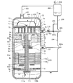
- FIG. 11 is a schematic vertical cross-sectional view of the entire configuration of the scroll compressor that constitutes the refrigeration cycle apparatus according to Embodiment 6 of the present invention.
- the gas-liquid separator 214 is installed at a branch point between the oil return circuit 204 and the oil return circuit 205.
- the gas-liquid separator 214 is connected to the separation vessel 214a, the inlet pipe 214b connected to the separation vessel 214a, the outlet pipe 214c connected to the bottom of the separation vessel 214a, and the side of the separation vessel 214a.
- an outlet pipe 214d The outlet pipe 214c corresponds to a first outlet pipe of the present invention, and the outlet pipe 214d corresponds to a second outlet pipe of the present invention.
- the outlet pipe 214 c is connected to the oil return circuit 204, and the outlet pipe 214 d is connected to the oil return circuit 205.
- the refrigerant and the oil are separated as described above, and the separated oil flows into the gas-liquid separator 214.
- a refrigerant containing oil may flow out of the oil separator 202 instead of a single oil.
- a gas-liquid separator 214 is provided at a branch point of the oil return circuit 204 and the oil return circuit 205 so that oil is supplied to the oil return circuit 204 with priority over the oil return circuit 205.
- the oil is separated from the refrigerant flowing from the inlet pipe 214b, and the separated oil is accumulated at the bottom of the separation container 214a.
- the oil accumulated at the bottom of the separation container 214a preferentially flows out of the outlet piping 214c connected to the bottom surface of the separation container 214a as compared with the outlet piping 214d connected to the side surface of the separation container 214a.
- the same effects as those of the first embodiment can be obtained, and the gas-liquid separator 214 is provided at the branch point of the oil return circuit 204 and the oil return circuit 205.
- oil is preferentially supplied to the oil return circuit 204. Therefore, the amount of oil returned to the positive displacement pump 111 can be secured.
- damage to the sliding portion due to insufficient oil supply can be suppressed, and a scroll compressor with higher reliability than in the case of the first embodiment can be provided.
- the gas-liquid separator 214 in which a plurality of pipes are connected to the separation container 214a is described as an example, but as shown in FIG. 12, a T-shaped pipe is used. It is good.
- FIG. 12 is a schematic vertical cross-sectional view of the entire configuration of a modified example of the scroll compressor that constitutes the refrigeration cycle apparatus according to Embodiment 6 of the present invention.
- a T-shaped tube 215 is provided as a gas-liquid separator.
- the T-shaped tube 215 is vertically connected to a vertical tube 215a which extends vertically and whose upper end opening is the inflow port 215aa and lower end opening is the outflow port 215ab, and is horizontally connected to the vertical pipe 215a and whose open end is the outflow port 215ba And a tube 215b.
- the inlet 215 aa communicates with the bottom of the oil separator 202, the outlet 215 ab communicates with the oil return circuit 204, and the outlet 215 ba communicates with the oil return circuit 205.
- the outlet 215ab corresponds to the first outlet of the present invention, and the outlet 215ba corresponds to the second outlet of the present invention.
- Embodiment 7 The seventh embodiment is intended to improve the lubrication of the bearing.
- the seventh embodiment will be described below focusing on the difference from the first embodiment.
- FIG. 13 is a schematic vertical cross-sectional view of the overall configuration of a scroll compressor that constitutes a refrigeration cycle apparatus according to a seventh embodiment of the present invention.
- the seventh embodiment has a configuration in which a through hole 216 communicating the boss internal space 74 and the bearing operation space 73 is provided in the boss 2d of the first embodiment shown in FIG.
- the same effects as those of the first embodiment can be obtained, and the following effects can be obtained by providing the through holes 216 in the boss 2 d.
- the pressure in the oil return circuit 204 is high, the installation space of the positive displacement pump 111 is low. For this reason, when high-pressure oil in the oil return circuit 204 is supplied to the low-pressure positive displacement pump 111, the pressure drops rapidly, and the refrigerant gas dissolved in the oil may foam. The refrigerant gas thus foamed rises in the oil hole 6da of the rotating shaft 6, and flows out from the upper end of the oil hole 6da to the boss internal space 74.
- the seventh embodiment can provide a scroll compressor having higher reliability than the first embodiment.
- the refrigeration cycle apparatus may be configured by appropriately combining the characteristic configurations of the respective embodiments.
- the through holes 216 may be provided in the boss 2 d of the scroll compressor 100 of FIG. 3 by combining the second embodiment and the seventh embodiment.
- Reference Signs List 1 fixed scroll, 1a fixed base plate, 1b fixed scroll, 1c discharge port, 2 swing scroll, 2a swing base plate, 2b swing scroll, 2c swing bearing, 2d boss portion, 3 compression mechanism, 3a swirl Parts, 6 rotation shafts, 6a eccentric shaft parts, 6b main shaft parts, 6c sub shaft parts, 6d axial flow channels, 6da oil holes, 6db oil holes, 7 frames, 7a injection ports, 7b main bearings, 7c communication flow paths, 8 compression chamber, 9 sub frame, 9a sub frame plate, 10 sub bearing, 11 discharge valve, 12 discharge muffler, 20 oil return piping, 60 first balance weight, 61 second balance weight, 70 spiral installation space, 71 shell suction Space, 72 shell discharge space, 73 bearing operation space, 74 boss internal space, 75 medium pressure space, 00 scroll compressor, 100a container, 100b oil reservoir, 101 suction pipe, 102 discharge pipe, 103 injection pipe, 103a outlet, 110 motor mechanism, 110a motor stator, 110b motor rotor, 111
Abstract
A scroll compressor constituting part of this refrigeration cycle device comprises a positive-displacement pump that supplies a storage oil in a container bottom part to a sliding part of a rotating shaft via an in-shaft flow path formed in the rotating shaft. The refrigeration cycle device comprises a return-oil circuit for returning the oil separated by an oil separation device to the scroll compressor. The downstream side of the return-oil circuit is divided into two branches, a first return-oil circuit outlet in one branch communicating with the positive-displacement pump, and a second return-oil circuit outlet in the other branch communicating with an injection circuit.
Description
本発明は、スクロール圧縮機を備えた冷凍サイクル装置に関する。
The present invention relates to a refrigeration cycle apparatus provided with a scroll compressor.
冷凍サイクル装置を構成するスクロール圧縮機は、固定スクロールと揺動スクロールとを組み合わせて形成した圧縮室にて冷媒を圧縮する圧縮機構と、電動機構と、電動機構の回転力を圧縮機構に伝達する回転軸とを容器内に備えている。このようなスクロール圧縮機では、回転軸の軸受等の摺動部を潤滑したり、圧縮機構の適宜箇所をシールしたりするために冷媒に油が混入されており、油が混入された冷媒が冷凍サイクル装置の配管内を循環している。
The scroll compressor constituting the refrigeration cycle apparatus transmits the rotational force of the electric mechanism and the electric mechanism to the compression mechanism, which compresses the refrigerant in the compression chamber formed by combining the fixed scroll and the oscillating scroll. A rotating shaft is provided in the container. In such a scroll compressor, oil is mixed in the refrigerant in order to lubricate sliding parts such as the bearing of the rotary shaft or to seal an appropriate part of the compression mechanism, and the refrigerant mixed with oil is It circulates in the piping of the refrigeration cycle device.
そして、スクロール圧縮機の運転中、油は冷媒と一緒にスクロール圧縮機の外部へ流出する。このため、冷凍サイクル装置においてスクロール圧縮機の下流には油分離器が設けられ、油分離器で分離された油を、返油回路を介してスクロール圧縮機の容器の底部の油溜めに返油するようにしている(例えば、特許文献1参照)。
And, during operation of the scroll compressor, the oil flows out of the scroll compressor together with the refrigerant. Therefore, an oil separator is provided downstream of the scroll compressor in the refrigeration cycle apparatus, and the oil separated by the oil separator is returned to the oil reservoir at the bottom of the scroll compressor container via the oil return circuit. (See, for example, Patent Document 1).
また、寒冷地域等の高い圧縮比が要求される運転条件では、スクロール圧縮機から吐出した冷媒の吐出温度が上昇し易い。このため、特許文献1では、スクロール圧縮機の容器外からインジェクション配管を接続し、インジェクション配管を介して圧縮機構内に液冷媒をインジェクションし、吐出温度の低減を図っている。
Further, under operating conditions where a high compression ratio is required, such as in cold regions, the discharge temperature of the refrigerant discharged from the scroll compressor tends to rise. For this reason, in patent document 1, the injection piping is connected from the container outside of a scroll compressor, liquid refrigerant is injected into the compression mechanism via the injection piping, and the discharge temperature is reduced.
このようなインジェクションが行われるスクロール圧縮機では、圧縮機構内に液冷媒をインジェクションすることで、圧縮機構内の油が液冷媒で希釈され、圧縮機構のシール性が悪化することがある。これに対し、特許文献1では、油分離器で分離した油をスクロール圧縮機へ戻す返油回路を2分岐し、一方は上述したように油溜めに返油し、他方はインジェクション配管に供給し、インジェクション配管の液冷媒に混合して圧縮機構に供給するようにしている。このように、圧縮機構に油を供給することで、圧縮機構のシール性を改善している。
In the scroll compressor in which such injection is performed, the oil in the compression mechanism may be diluted with the liquid refrigerant by injecting the liquid refrigerant into the compression mechanism, and the sealability of the compression mechanism may be deteriorated. On the other hand, in Patent Document 1, the oil separated in the oil separator is returned to the scroll compressor, and the oil return circuit is branched into two, one returns the oil to the oil reservoir as described above, and the other feeds the injection pipe. The liquid refrigerant is mixed with the liquid refrigerant in the injection pipe and supplied to the compression mechanism. Thus, by supplying oil to the compression mechanism, the sealability of the compression mechanism is improved.
特許文献1では、上述したように、油分離器で分離した油を、油溜めと圧縮機構とに分けて戻すようにしているが、圧縮機構に戻された油は、圧縮機構で圧縮された冷媒と共にスクロール圧縮機の外部に再流出しやすい。このため、特に高速運転時に圧縮機構から流出する油量が増大し、油溜めの油が枯渇することで、軸受等の摺動部における給油不足が生じ、スクロール圧縮機の信頼性が低下する課題がある。
In Patent Document 1, as described above, the oil separated by the oil separator is divided back into the oil reservoir and the compression mechanism, but the oil returned to the compression mechanism is compressed by the compression mechanism. It tends to flow out of the scroll compressor together with the refrigerant. For this reason, the amount of oil flowing out from the compression mechanism increases particularly at high speed operation, and the oil in the oil reservoir is depleted, causing insufficient oil supply at sliding parts such as bearings, and a problem of the reliability of the scroll compressor being lowered. There is.
本発明はこのような点を鑑みなされたもので、高速運転時における圧縮機外部への油流出を抑制することが可能な冷凍サイクル装置を提供することを目的とする。
The present invention has been made in view of such a point, and an object of the present invention is to provide a refrigeration cycle apparatus capable of suppressing oil outflow to the outside of the compressor during high speed operation.
本発明に係る冷凍サイクル装置は、スクロール圧縮機と、凝縮器と、減圧装置と、蒸発器とを備え、油を含む冷媒が循環する主回路と、凝縮器と減圧装置との間から分岐してスクロール圧縮機に接続されるインジェクション回路と、主回路に設けられ、スクロール圧縮機から吐出された冷媒から油を分離する油分離器と、油分離器で分離した油をスクロール圧縮機へ返油する返油回路とを備え、スクロール圧縮機は、底部が油溜めとなる容器と、容器内に収容された電動機構と、容器内に収容され、揺動スクロール及び固定スクロールを組み合わせて形成した圧縮室にて冷媒を圧縮する圧縮機構と、電動機構と圧縮機構とを連結し、電動機構の回転力を圧縮機構に伝達する回転軸と、油溜めの油を、回転軸に形成された軸内流路を介して回転軸の摺動部に供給する容積型ポンプとを備え、返油回路は、下流側が2分岐されて一方の第1返油回路の出口が容積型ポンプに連通し、他方の第2返油回路の出口がインジェクション回路に連通しているものである。
The refrigeration cycle apparatus according to the present invention includes a scroll compressor, a condenser, a pressure reducing device, and an evaporator, and is branched from between a main circuit in which a refrigerant containing oil circulates, and between the condenser and the pressure reducing device. And an oil separator provided in the main circuit to separate oil from the refrigerant discharged from the scroll compressor, and oil returned by the oil separator being returned to the scroll compressor The scroll compressor includes a container whose bottom is an oil reservoir, a motorized mechanism housed in the container, and a compressor which is housed in the container and formed by combining a swing scroll and a fixed scroll. The compression mechanism that compresses the refrigerant in the chamber, the motor-driven mechanism and the compression mechanism are connected, and the rotary shaft that transmits the rotational force of the motor-driven mechanism to the compression mechanism Through the flow path The oil return circuit is bifurcated on the downstream side with the outlet of one of the first oil return circuits communicating with the displacement pump and the other second oil return circuit. The outlet of the valve is in communication with the injection circuit.
本発明によれば、油分離器で分離した油をスクロール圧縮機へ返油する返油回路の下流側を2分岐し、一方の第1返油回路の出口を容積型ポンプに連通し、他方の第2返油回路の出口をインジェクション回路に連通する構成とした。このように、油分離器で分離した油を、油溜めではなく、容積型ポンプに直接、戻す第1返油回路を構成したことで、高速運転時に、油分離器から第1返油回路を介して回転軸の軸内流路への返油される油量を、低速運転時よりも相対的に増加することができる。その結果、高速運転時における圧縮機外部への油流出を抑制することができる。
According to the present invention, the downstream side of the oil return circuit for returning the oil separated by the oil separator to the scroll compressor is bifurcated, and the outlet of one of the first oil return circuits is communicated with the positive displacement pump, The outlet of the second oil return circuit is connected to the injection circuit. Thus, by configuring the first oil return circuit that directly returns the oil separated by the oil separator to the positive displacement pump instead of the oil reservoir, the first oil return circuit from the oil separator is operated at high speed. It is possible to relatively increase the amount of oil returned to the in-axis flow passage of the rotating shaft via the rotation shaft as compared with the low speed operation. As a result, it is possible to suppress oil outflow to the outside of the compressor during high speed operation.
以下、本発明の実施の形態に係る冷凍サイクル装置について図面を参照しながら説明する。ここで、図1を含め、以下の図面において、同一の符号を付したものは、同一又はこれに相当するものであり、以下に記載する実施の形態の全文において共通することとする。そして、明細書全文に表わされている構成要素の形態は、あくまでも例示であって、明細書に記載された形態に限定するものではない。また、圧力及び圧縮比の高低については、特に絶対的な値との関係で高低が定まっているものではなく、システム及び装置等における状態及び動作等において相対的に定まるものとする。
Hereinafter, a refrigeration cycle apparatus according to an embodiment of the present invention will be described with reference to the drawings. Here, in the following drawings including FIG. 1, those given the same reference numerals are the same or correspond to these, and are common to the whole text of the embodiments described below. And the form of the component expressed to the whole specification is only an illustration, and is not limited to the form described in the specification. The high and low levels of the pressure and the compression ratio are not particularly determined in relation to absolute values, but are relatively determined in the state and operation of the system and apparatus.
実施の形態1.
図1は、本発明の実施の形態1に係る冷凍サイクル装置を構成するスクロール圧縮機の全体構成の概略縦断面図である。図1において矢印は冷媒及び油の流れを示している。後述の図においても同様である。
スクロール圧縮機100は、圧縮機構3と、電動機構110と、その他の構成部品とを有している。スクロール圧縮機100はこれらの構成部品が、外郭を構成する容器100aの内部に収容された構成を有している。圧縮機構3と電動機構110とは回転軸6を介して連結されており、電動機構110の発生する回転力が回転軸6を介して圧縮機構3に伝達され、その回転力によって圧縮機構3で冷媒が圧縮されるようになっている。Embodiment 1
FIG. 1 is a schematic vertical cross-sectional view of the overall configuration of a scroll compressor that constitutes a refrigeration cycle apparatus according toEmbodiment 1 of the present invention. Arrows in FIG. 1 indicate flows of refrigerant and oil. The same applies to the figures described later.
Thescroll compressor 100 has a compression mechanism 3, an electric mechanism 110, and other components. The scroll compressor 100 has a configuration in which these components are housed inside a container 100a constituting an outer shell. The compression mechanism 3 and the motor-driven mechanism 110 are connected via the rotary shaft 6, and the rotational force generated by the motor-driven mechanism 110 is transmitted to the compression mechanism 3 via the rotary shaft 6. The refrigerant is adapted to be compressed.
図1は、本発明の実施の形態1に係る冷凍サイクル装置を構成するスクロール圧縮機の全体構成の概略縦断面図である。図1において矢印は冷媒及び油の流れを示している。後述の図においても同様である。
スクロール圧縮機100は、圧縮機構3と、電動機構110と、その他の構成部品とを有している。スクロール圧縮機100はこれらの構成部品が、外郭を構成する容器100aの内部に収容された構成を有している。圧縮機構3と電動機構110とは回転軸6を介して連結されており、電動機構110の発生する回転力が回転軸6を介して圧縮機構3に伝達され、その回転力によって圧縮機構3で冷媒が圧縮されるようになっている。
FIG. 1 is a schematic vertical cross-sectional view of the overall configuration of a scroll compressor that constitutes a refrigeration cycle apparatus according to
The
容器100aには、冷媒を吸入するための吸入管101と、冷媒を吐出するための吐出管102と、後述のインジェクション冷媒を圧縮機構3内に吸入するためのインジェクション配管103とが設けられている。インジェクション配管103は吸入管101とは別に、容器100a内の圧縮機構3に冷媒を導入するためのものである。インジェクション配管103は、後述のフレーム7に形成されたインジェクションポート7aに接続されている。
The container 100a is provided with a suction pipe 101 for suctioning the refrigerant, a discharge pipe 102 for discharging the refrigerant, and an injection pipe 103 for suctioning an injection refrigerant described later into the compression mechanism 3 . The injection pipe 103 is for introducing a refrigerant into the compression mechanism 3 in the container 100 a separately from the suction pipe 101. The injection pipe 103 is connected to an injection port 7 a formed in a frame 7 described later.
容器100aの内部には、圧縮機構3を容器100aに固定するフレーム7とサブフレーム9とが配置されている。フレーム7は、電動機構110の上側であって圧縮機構3の下側に配置され、焼嵌め又は溶接等によって容器100aの内周面に固着されている。フレーム7には、吸入管101から流入した冷媒を圧縮機構3内に導く連通流路7cが形成されている。
Inside the container 100a, a frame 7 and a sub-frame 9 for fixing the compression mechanism 3 to the container 100a are disposed. The frame 7 is disposed on the upper side of the electromotive mechanism 110 and on the lower side of the compression mechanism 3 and is fixed to the inner circumferential surface of the container 100a by shrink fitting, welding or the like. A communication channel 7 c for guiding the refrigerant flowing from the suction pipe 101 into the compression mechanism 3 is formed in the frame 7.
サブフレーム9は、電動機構110の下側に配置され、サブフレームプレート9aを介して焼嵌め又は溶接等によって容器100aの内周面に固着されている。そして、サブフレーム9の下方には、上端面で回転軸6を軸方向に支承するようにして容積型ポンプ111が取り付けられている。
The sub-frame 9 is disposed below the motor-driven mechanism 110, and is fixed to the inner circumferential surface of the container 100a by shrink fitting, welding or the like via the sub-frame plate 9a. A displacement pump 111 is attached to the lower end of the sub-frame 9 so as to axially support the rotary shaft 6 at the upper end face.
回転軸6には軸内流路6dが設けられている。軸内流路6dは回転軸6の中心部を軸方向に延びる油穴6daと、油穴6daに連通して半径方向に延びる複数の給油穴6dbとを有する。給油穴6dbは、揺動軸受2c、主軸受7b及び副軸受10のそれぞれと対向する位置に形成されており、回転軸6の摺動部である、これらの各軸受に容積型ポンプ111から供給された油を供給するようになっている。揺動軸受2c等に供給された油は、後述の軸受動作空間73から返油パイプ113を通って油溜め100bに戻される。
The rotation shaft 6 is provided with an in-shaft flow passage 6 d. The in-shaft flow path 6d has an oil hole 6da axially extending in the central portion of the rotary shaft 6, and a plurality of oil supply holes 6db communicating radially with the oil hole 6da. The oil supply hole 6db is formed at a position facing each of the rocking bearing 2c, the main bearing 7b, and the auxiliary bearing 10, and is a sliding portion of the rotating shaft 6, and supplied from the positive displacement pump 111 to each of these bearings. To supply the The oil supplied to the rocking bearing 2c and the like is returned from the bearing operation space 73 described later through the oil return pipe 113 to the oil reservoir 100b.
容積型ポンプ111には吸入パイプ111aの一端が接続され、吸入パイプ111aの他端は油溜め100b内に浸漬しており、油溜め100b内の油を吸い上げて回転軸6の軸内流路6dに供給する。
One end of the suction pipe 111a is connected to the positive displacement pump 111, and the other end of the suction pipe 111a is immersed in the oil reservoir 100b to suck up the oil in the oil reservoir 100b to flow the inner flow passage 6d of the rotating shaft 6 Supply to
圧縮機構3は、固定スクロール1と揺動スクロール2とを有している。固定スクロール1は、フレーム7に対して固定配置されている。揺動スクロール2は、固定スクロール1の下側に配置されて回転軸6の後述の偏心軸部6aに揺動自在に支持されている。
The compression mechanism 3 has a fixed scroll 1 and an oscillating scroll 2. The fixed scroll 1 is fixed to the frame 7. The swing scroll 2 is disposed below the fixed scroll 1 and swingably supported by an eccentric shaft portion 6 a described later of the rotation shaft 6.
固定スクロール1は、固定台板1aと、固定台板1aの一方の面に立てて設けられた固定渦巻体1bと、を有している。揺動スクロール2は、揺動台板2aと、揺動台板2aの一方の面に立てて設けられた揺動渦巻体2bと、を有している。固定スクロール1及び揺動スクロール2は、固定渦巻体1bと揺動渦巻体2bとを回転軸6の回転中心に対して逆位相で噛み合わせた対称渦巻形状の状態で容器100a内に配置されている。そして、固定渦巻体1bと揺動渦巻体2bとの間には、回転軸6の回転に伴い、半径方向外側から内側へ向かうに従って容積が縮小する圧縮室8が形成されている。以下、揺動スクロール2と固定スクロール1とで構成された圧縮機構3のうち、特に揺動渦巻体2bと固定渦巻体1bとを組み合わせた対称渦巻形状の構造体部分を、渦巻部3aという。
The fixed scroll 1 has a fixed base plate 1a and a fixed scroll 1b provided upright on one surface of the fixed base plate 1a. The rocking scroll 2 has a rocking bed plate 2a and a rocking scroll 2b provided upright on one surface of the rocking bed plate 2a. The fixed scroll 1 and the rocking scroll 2 are disposed in the container 100 a in a symmetrical spiral shape in which the fixed scroll 1 b and the rocking scroll 2 b are meshed in the reverse phase with respect to the rotation center of the rotating shaft 6 There is. A compression chamber 8 is formed between the fixed scroll 1b and the swinging scroll 2b, the volume of which decreases as it goes from the radially outer side to the inner side as the rotary shaft 6 rotates. Hereinafter, in the compression mechanism 3 constituted by the rocking scroll 2 and the fixed scroll 1, a structure portion having a symmetrical spiral shape in which the rocking scroll 2b and the fixed scroll 1b are combined in particular is referred to as a spiral portion 3a.
また、固定スクロール1の固定台板1aには圧縮室8に連通する吐出ポート1cが貫通形成されており、その吐出ポート1cには吐出バルブ11が設けられている。そして、この吐出ポート1cを覆うように吐出マフラ12が取り付けられている。
Further, a discharge port 1c communicating with the compression chamber 8 is formed through the fixed base plate 1a of the fixed scroll 1 and a discharge valve 11 is provided in the discharge port 1c. And the discharge muffler 12 is attached so that this discharge port 1c may be covered.
揺動スクロール2の揺動台板2aにおいて揺動渦巻体2b形成面とは反対側の面(以下、背面という)の略中心部には、円筒形状のボス部2dが形成されている。ボス部2dの内側には、揺動軸受2cが配置され、揺動軸受2cの内側に、回転軸6の上端部に形成された偏心軸部6aが嵌合されている。
A cylindrical boss 2d is formed substantially at the center of the surface (hereinafter referred to as the back surface) opposite to the surface on which the rocking scroll 2b is formed in the rocking base plate 2a of the rocking scroll 2. A rocking bearing 2c is disposed inside the boss 2d, and an eccentric shaft 6a formed on the upper end of the rotary shaft 6 is fitted inside the rocking bearing 2c.
回転軸6は、回転軸6の上部の偏心軸部6aと、主軸部6bと、回転軸6の下部の副軸部6cと、で構成されている。偏心軸部6aは、揺動軸受2cを介して揺動スクロール2のボス部2dに回転自在に嵌め合わされ、油による油膜を介して揺動軸受2cと摺動する。揺動軸受2cは、滑り軸受に使用される銅鉛合金等の軸受材料を圧入するなどしてボス部2d内に固定されている。そして、回転軸6の回転により揺動スクロール2が揺動運動するようになっている。主軸部6bは、フレーム7に設けられた主軸受7bに回転自在に嵌め合わされ、油による油膜を介して主軸受7bと摺動する。主軸受7bは、滑り軸受に使用される銅鉛合金等の軸受材料を圧入するなどしてフレーム7に固定されている。
The rotating shaft 6 is composed of an eccentric shaft 6 a at the upper part of the rotating shaft 6, a main shaft 6 b, and a sub shaft 6 c at the lower part of the rotating shaft 6. The eccentric shaft 6a is rotatably fitted to the boss 2d of the rocking scroll 2 via the rocking bearing 2c, and slides on the rocking bearing 2c via an oil film of oil. The rocking bearing 2c is fixed in the boss portion 2d by press-fitting a bearing material such as a copper-lead alloy used for a sliding bearing. The rocking scroll 2 is rocked by the rotation of the rotary shaft 6. The main shaft portion 6b is rotatably fitted to the main bearing 7b provided on the frame 7, and slides with the main bearing 7b via an oil film of oil. The main bearing 7b is fixed to the frame 7 by press-fitting or the like of a bearing material such as a copper-lead alloy used for a slide bearing.
サブフレーム9の中央部は、玉軸受からなる副軸受10を備え、電動機構110の下方で回転軸6を半径方向に軸支する。なお、副軸受10は、玉軸受以外の別の軸受構成としてもよい。回転軸6の副軸部6cは、副軸受10と嵌め合わされ、副軸受10と摺動する。主軸部6b及び副軸部6cの軸心は、回転軸6の軸心と一致している。
The central portion of the sub-frame 9 is provided with a sub bearing 10 composed of a ball bearing, and supports the rotating shaft 6 in the radial direction below the electric mechanism 110. The auxiliary bearing 10 may have another bearing configuration other than the ball bearing. The countershaft 6 c of the rotating shaft 6 is fitted to the subbearing 10 and slides on the subbearing 10. The axial centers of the main shaft portion 6 b and the auxiliary shaft portion 6 c coincide with the axial center of the rotation shaft 6.
ここで、容器100a内の空間を以下のように定義する。容器100aの内部空間のうち、フレーム7の上面に形成された凹部の内壁と、圧縮機構3の揺動渦巻体2bと固定渦巻体1bとを噛み合わせた構造体部分の最外周面とで形成される空間を渦巻設置空間70という。また、容器100aの内部空間のうち、フレーム7よりも下側の空間をシェル吸入空間71という。シェル吸入空間71は吸入管101から流入された吸入冷媒で満たされた低圧空間となっている。また、容器100aの内部空間のうち、圧縮機構3の固定台板1aより吐出管102側の空間をシェル吐出空間72という。また、容器100aの内部空間のうち、揺動軸受2cを収容し、揺動軸受2cが回転動作するためにフレーム7内に形成されている空間を軸受動作空間73という。また、回転軸6の上端と揺動スクロール2の揺動台板2aとの間であってボス部2dの内側空間をボス部内部空間74という。
Here, the space in the container 100a is defined as follows. Of the internal space of the container 100a, it is formed by the inner wall of the recess formed on the upper surface of the frame 7 and the outermost peripheral surface of the structure portion in which the swinging scroll 2b of the compression mechanism 3 and the fixed scroll 1b are engaged. This space is called a spiral installation space 70. Further, the space below the frame 7 in the internal space of the container 100 a is referred to as a shell suction space 71. The shell suction space 71 is a low pressure space filled with the suction refrigerant introduced from the suction pipe 101. Further, in the internal space of the container 100 a, the space on the discharge pipe 102 side from the fixed base plate 1 a of the compression mechanism 3 is referred to as a shell discharge space 72. Further, in the internal space of the container 100a, a space formed in the frame 7 for accommodating the rocking bearing 2c and rotating the rocking bearing 2c is referred to as a bearing operation space 73. Further, an inner space between the upper end of the rotary shaft 6 and the swing base plate 2 a of the swing scroll 2 and an inner space of the boss 2 d is referred to as a boss inner space 74.
電動機構110は、電動機固定子110aと電動機回転子110bとを有している。電動機固定子110aは、外部から電力を得るために、フレーム7と電動機固定子110aとの間に存在する図示しないガラス端子に図示しないリード線で接続されている。また、電動機回転子110bは、回転軸6に焼嵌め等によって固定されている。また、スクロール圧縮機100の回転系全体のバランシングを行うため、回転軸6には、第1バランスウェイト60が固定されていると共に、電動機回転子110bには、第2バランスウェイト61が固定されている。
The electromotive mechanism 110 has a motor stator 110a and a motor rotor 110b. The motor stator 110a is connected by a lead wire (not shown) to a glass terminal (not shown) present between the frame 7 and the motor stator 110a in order to obtain power from the outside. The motor rotor 110 b is fixed to the rotating shaft 6 by shrink fitting or the like. Further, in order to balance the entire rotation system of the scroll compressor 100, the first balance weight 60 is fixed to the rotation shaft 6, and the second balance weight 61 is fixed to the motor rotor 110b. There is.
以上のように構成されたスクロール圧縮機100内には、吸入管101から冷媒と共に油が流入する。油は、摺動部の潤滑性向上と、圧縮室8の隙間漏れを抑制するためのシール機能とを目的として用いられている。そして、スクロール圧縮機100の下流には、スクロール圧縮機100から吐出された冷媒から油を分離する油分離器202が配置されている。以下、スクロール圧縮機100と油分離器202とを備えた冷凍サイクル装置300について説明する。
Into the scroll compressor 100 configured as described above, oil flows from the suction pipe 101 together with the refrigerant. The oil is used for the purpose of improving the lubricity of the sliding portion and the sealing function for suppressing the gap leak of the compression chamber 8. An oil separator 202 is disposed downstream of the scroll compressor 100 to separate oil from the refrigerant discharged from the scroll compressor 100. Hereinafter, a refrigeration cycle apparatus 300 including the scroll compressor 100 and the oil separator 202 will be described.
図2は、本発明の実施の形態1に係る冷凍サイクル装置の冷媒回路図である。
冷凍サイクル装置300は、スクロール圧縮機100と、油分離器202と、凝縮器301と、膨張弁又はキャピラリーチューブ等で構成された減圧装置302と、蒸発器303とを順に冷媒配管で接続され、冷媒が循環する主回路300aを備えている。 FIG. 2 is a refrigerant circuit diagram of the refrigeration cycle apparatus according toEmbodiment 1 of the present invention.
In therefrigeration cycle apparatus 300, a scroll compressor 100, an oil separator 202, a condenser 301, a decompression device 302 including an expansion valve or a capillary tube, and an evaporator 303 are sequentially connected by refrigerant piping. A main circuit 300a through which the refrigerant circulates is provided.
冷凍サイクル装置300は、スクロール圧縮機100と、油分離器202と、凝縮器301と、膨張弁又はキャピラリーチューブ等で構成された減圧装置302と、蒸発器303とを順に冷媒配管で接続され、冷媒が循環する主回路300aを備えている。 FIG. 2 is a refrigerant circuit diagram of the refrigeration cycle apparatus according to
In the
冷凍サイクル装置300は更に、凝縮器301と減圧装置302との間から分離してスクロール圧縮機100のインジェクション配管103に接続されるインジェクション回路305を備えている。インジェクション回路305には、流量調整弁としての膨張弁304が設けられており、インジェクションする流量を調整可能となっている。油分離器202は、スクロール圧縮機100の吐出管102と回路201で接続されている。減圧装置302の開度、膨張弁304の開度及びスクロール圧縮機100の回転数は、図示しない制御装置によって制御される。
The refrigeration cycle apparatus 300 further includes an injection circuit 305 separated from between the condenser 301 and the pressure reducing device 302 and connected to the injection pipe 103 of the scroll compressor 100. The injection circuit 305 is provided with an expansion valve 304 as a flow rate adjustment valve, so that the flow rate to be injected can be adjusted. The oil separator 202 is connected to the discharge pipe 102 of the scroll compressor 100 by a circuit 201. The opening degree of the pressure reducing device 302, the opening degree of the expansion valve 304, and the rotation speed of the scroll compressor 100 are controlled by a control device (not shown).
なお、冷凍サイクル装置300に更に図示しない四方弁を設け、冷媒の流れ方向を逆に切り替えるようにしてもよい。この場合、スクロール圧縮機100の下流側に設置した凝縮器301を室内機側、蒸発器303を室外機側とすれば暖房運転となり、凝縮器301を室外機側、蒸発器303を室内機側とすれば冷房運転となる。
In addition, a four-way valve (not shown) may be further provided in the refrigeration cycle apparatus 300 to switch the flow direction of the refrigerant in the reverse direction. In this case, if the condenser 301 installed downstream of the scroll compressor 100 is the indoor unit side and the evaporator 303 is the outdoor unit side, the heating operation is performed, and the condenser 301 is the outdoor unit side and the evaporator 303 is the indoor unit side. If it does, it will be cooling operation.
そして、本実施の形態1の特徴として、油分離器202内の油を、スクロール圧縮機100に戻す返油回路206の下流を2分岐し、一方の返油回路204の出口を、容器100aの底部の油溜め100bではなく、容積型ポンプ111に直接連通した構成としたことにある。そして、他方の返油回路205の出口は、インジェクション回路305に連通した構成としている。なお、返油回路204から戻る油は、主に軸受を潤滑するものであり、返油回路205から戻る油は、圧縮機構3のシール性を向上するものである。ここで、返油回路204が本発明の第1返油回路に相当し、返油回路205が本発明の第2返油回路に相当する。
Then, as a feature of the first embodiment, the oil in the oil separator 202 is returned to the scroll compressor 100 into two branches downstream of the oil return circuit 206, and the outlet of one oil return circuit 204 is the container 100a. This configuration is in direct communication with the positive displacement pump 111 instead of the oil reservoir 100 b at the bottom. The outlet of the other oil return circuit 205 is in communication with the injection circuit 305. The oil returned from the oil return circuit 204 mainly lubricates the bearings, and the oil returned from the oil return circuit 205 improves the sealability of the compression mechanism 3. Here, the oil return circuit 204 corresponds to a first oil return circuit of the present invention, and the oil return circuit 205 corresponds to a second oil return circuit of the present invention.
容積型ポンプ111は、回転軸6の回転数が高くなると、返油回路204からポンプ内に吸入されて軸内流路6dに吐出される油量が増加する。また、吸入パイプ111aからポンプ内に吸入される油量も増加する。よって、高速運転時では、油分離器202から返油回路204を介して軸内流路6dへの返油される油量を、低速運転時よりも相対的に増加することができる。このため、高速運転時には、軸内流路6dに積極的に返油され、インジェクション回路305から圧縮機構3へ供給される返油量が抑制されることになる。その結果、圧縮機構3から圧縮機外部への油流出を抑制することができる。
When the rotational speed of the rotary shaft 6 becomes high, the volume of the positive displacement pump 111 is drawn into the pump from the oil return circuit 204 and the amount of oil discharged to the in-shaft flow path 6 d increases. In addition, the amount of oil sucked into the pump from the suction pipe 111a also increases. Therefore, at the time of high speed operation, the amount of oil returned from the oil separator 202 to the in-shaft flow path 6 d via the oil return circuit 204 can be relatively increased as compared to that at low speed operation. Therefore, during high-speed operation, oil is positively returned to the in-shaft flow path 6d, and the amount of oil returned from the injection circuit 305 to the compression mechanism 3 is suppressed. As a result, oil outflow from the compression mechanism 3 to the outside of the compressor can be suppressed.
また、低速運転時は、油分離器202からインジェクション回路305へ積極的に油を供給することで、圧縮機構3のシール性を向上することができる。
In addition, during low speed operation, by actively supplying oil from the oil separator 202 to the injection circuit 305, the sealability of the compression mechanism 3 can be improved.
ここで、返油回路206の具体的な構成としては、返油回路204を構成する配管が返油回路205との分岐点よりも上流に延長されて油分離器202の底部に接続されている。また、返油回路204を構成する配管の下流端を容器100aを貫通して容積型ポンプ111の吸入口に接続した構成としている。返油回路205の具体的な構成としては、返油回路205を構成する配管の上流端を返油回路204の配管に接続し、下流端をインジェクション回路305の配管に接続した構成としている。
Here, as a specific configuration of the oil return circuit 206, a pipe constituting the oil return circuit 204 is extended upstream of a branch point with the oil return circuit 205 and connected to the bottom of the oil separator 202. . Further, the downstream end of the pipe constituting the oil return circuit 204 is configured to penetrate the container 100 a and be connected to the suction port of the positive displacement pump 111. As a specific configuration of the oil return circuit 205, the upstream end of the pipe constituting the oil return circuit 205 is connected to the pipe of the oil return circuit 204, and the downstream end is connected to the pipe of the injection circuit 305.
また、容積型ポンプ111において、吸入パイプ111aと返油回路204とのように導入圧力の異なる複数の供給源から油を容積型ポンプ111内に導入するためには、以下の構成とされていればよい。すなわち、例えば、容積型ポンプ111内のポンプ室(図示せず)は、まず低圧の吸入パイプ111aにつながり、回転するにつれて容積が拡大して吸入パイプ111aから油を吸入し、その後、吸入パイプ111aとのつながりを閉じる。次いで、ポンプ室(図示せず)は、高圧の返油回路204の配管につながり、更に容積が拡大して返油回路204の油を吸入し、その後、返油回路204の配管とのつながりを閉じる。その後、ポンプ室(図示せず)は軸内流路6dにつながり、容積が減少して吸入した油を軸内流路6dに吐出し、軸内流路6dとのつながりを閉じて最初に戻る。容積型ポンプ111には、このように動作する構成の容積型ポンプを使用できる。
Further, in order to introduce oil into the positive displacement pump 111 from a plurality of supply sources with different introduction pressures such as the suction pipe 111 a and the oil return circuit 204 in the positive displacement pump 111, the following configuration is adopted. Just do it. That is, for example, a pump chamber (not shown) in the positive displacement pump 111 is first connected to the low pressure suction pipe 111a, and its volume is expanded as it rotates to suck oil from the suction pipe 111a, and then the suction pipe 111a Close the connection with Next, the pump chamber (not shown) is connected to the high pressure oil return circuit 204 piping, and the volume is further expanded to suck in the oil of the oil return circuit 204, and then the connection with the oil return circuit 204 piping close up. Thereafter, the pump chamber (not shown) is connected to the in-shaft channel 6d, and the volume is reduced, and the sucked oil is discharged to the in-shaft channel 6d to close the connection with the in-shaft channel 6d and return first. . As the positive displacement pump 111, a positive displacement pump configured to operate in this manner can be used.
次に冷媒の流れについて説明する。
Next, the flow of the refrigerant will be described.
主回路300aにおいて、スクロール圧縮機100から吐出された冷媒は、油分離器202に流入する。油分離器202では、冷媒と冷媒に混ざっている油とが分離され、分離された冷媒は、凝縮器301で冷却される。凝縮器301で冷却された冷媒は、減圧装置302で減圧された後、蒸発器303で加熱され、冷媒ガスとなる。蒸発器303から流出した冷媒ガスはスクロール圧縮機100に戻る。スクロール圧縮機100に戻る冷媒は、吸入管101から容器100a内に流入する。
In the main circuit 300 a, the refrigerant discharged from the scroll compressor 100 flows into the oil separator 202. In the oil separator 202, the refrigerant and the oil mixed in the refrigerant are separated, and the separated refrigerant is cooled by the condenser 301. The refrigerant cooled by the condenser 301 is reduced in pressure by the pressure reducing device 302 and then heated by the evaporator 303 to become a refrigerant gas. The refrigerant gas flowing out of the evaporator 303 returns to the scroll compressor 100. The refrigerant returning to the scroll compressor 100 flows into the container 100 a from the suction pipe 101.
吸入管101から容器100a内のシェル吸入空間71に流入した低圧冷媒は、フレーム7に形成された連通流路7cを通過して渦巻設置空間70に流入する。渦巻設置空間70に流入した冷媒は、インジェクション配管103からインジェクションポート7aを介して流入した冷媒と混合する。そして、混合した冷媒は、固定スクロール1の固定渦巻体1bと揺動スクロール2の揺動渦巻体2bとの相対的な揺動動作に伴って圧縮室8へと吸い込まれる。吸い込まれた冷媒は、揺動スクロール2の動作に伴う圧縮室8の幾何学的な容積変化によって低圧から高圧へと昇圧される。
The low-pressure refrigerant flowing from the suction pipe 101 into the shell suction space 71 in the container 100 a passes through the communication flow path 7 c formed in the frame 7 and flows into the spiral installation space 70. The refrigerant flowing into the swirl installation space 70 mixes with the refrigerant flowing from the injection pipe 103 via the injection port 7 a. Then, the mixed refrigerant is drawn into the compression chamber 8 along with the relative swing operation of the fixed scroll 1 b of the fixed scroll 1 and the swing scroll 2 b of the swing scroll 2. The sucked refrigerant is boosted from low pressure to high pressure by the geometric volume change of the compression chamber 8 accompanying the operation of the oscillating scroll 2.
そして、圧縮室8の冷媒の圧力がシェル吐出空間72の圧力よりも大きくなると、吐出バルブ11が開口し、固定スクロール1に設置された吐出ポート1cより冷媒がシェル吐出空間72へと吐出される。その後、吐出された冷媒は、シェル吐出空間72を経由して吐出管102から高圧冷媒として圧縮機外部の回路201へと吐出される。スクロール圧縮機から吐出された回路201の冷媒は、油分離器202に流入し、冷媒中に含まれる油を分離したのち、凝縮器301へ向かう回路203へと流出する。
Then, when the pressure of the refrigerant in the compression chamber 8 becomes larger than the pressure of the shell discharge space 72, the discharge valve 11 is opened, and the refrigerant is discharged to the shell discharge space 72 from the discharge port 1c installed in the fixed scroll 1. . Thereafter, the discharged refrigerant is discharged from the discharge pipe 102 via the shell discharge space 72 as a high pressure refrigerant to the circuit 201 outside the compressor. The refrigerant of the circuit 201 discharged from the scroll compressor flows into the oil separator 202, separates the oil contained in the refrigerant, and then flows out to the circuit 203 directed to the condenser 301.
また、凝縮器301で冷却された冷媒の一部は、インジェクション回路305に流入し、膨張弁304を経てスクロール圧縮機100のインジェクション配管103に流入する。インジェクション配管103に流入した液又は二相のインジェクション冷媒は、渦巻設置空間70を通り、圧縮機構3内の吸入室に流入する。
Further, part of the refrigerant cooled by the condenser 301 flows into the injection circuit 305, and flows through the expansion valve 304 into the injection pipe 103 of the scroll compressor 100. The liquid or two-phase injection refrigerant flowing into the injection pipe 103 passes through the swirl installation space 70 and flows into the suction chamber in the compression mechanism 3.
次に、油の流れについて説明する。
Next, the flow of oil will be described.
スクロール圧縮機100から流出した油は、油分離器202で分離され、返油回路206を通り、スクロール圧縮機100へ供給される。返油回路206において、返油回路204は容積型ポンプ111の吸入口に接続されている。このため、油分離器202内に溜められた油は、容積型ポンプ111の吸入口から回転軸6の軸内流路6dへ供給される。そして、軸内流路6dに供給された油は、揺動軸受2c、主軸受7b及び副軸受10等の摺動部に供給される。
The oil that has flowed out of the scroll compressor 100 is separated by the oil separator 202, passes through the oil return circuit 206, and is supplied to the scroll compressor 100. In the oil return circuit 206, the oil return circuit 204 is connected to the suction port of the positive displacement pump 111. Therefore, the oil stored in the oil separator 202 is supplied from the suction port of the positive displacement pump 111 to the in-shaft flow path 6 d of the rotating shaft 6. Then, the oil supplied to the in-shaft flow path 6d is supplied to the sliding portions such as the rocking bearing 2c, the main bearing 7b, and the sub bearing 10.
摺動部に供給された油の一部は、揺動軸受2c及び主軸受7bの下流側に設置された軸受動作空間73に供給される。その後、軸受動作空間73に供給された油は、返油パイプ113を通って容器100aの油溜め100bに貯蔵される。油溜め100bに貯蔵された油の一部は、回転軸6の回転により容積型ポンプ111が動作することで、吸入パイプ111aから吸い上げられ、再び摺動部に供給される。また、油溜め100bに貯蔵された油の一部は、吸入管101から流入した冷媒の流れによって巻き上げられ、連通流路7cを通って圧縮機構3に流入した後、スクロール圧縮機100の外部へと流出する。
A portion of the oil supplied to the sliding portion is supplied to a bearing operation space 73 installed downstream of the rocking bearing 2c and the main bearing 7b. Thereafter, the oil supplied to the bearing operation space 73 is stored in the oil reservoir 100b of the container 100a through the oil return pipe 113. Part of the oil stored in the oil reservoir 100b is sucked from the suction pipe 111a by the operation of the positive displacement pump 111 by the rotation of the rotary shaft 6, and is supplied again to the sliding portion. Further, a part of the oil stored in the oil reservoir 100b is wound up by the flow of the refrigerant flowing from the suction pipe 101, flows into the compression mechanism 3 through the communication flow path 7c, and then to the outside of the scroll compressor 100. And flow out.
また、返油回路205は、下流側がインジェクション回路305に接続されている。このため、油分離器202内に溜められた油は、返油回路205からインジェクション回路305のインジェクション冷媒に供給され、インジェクション冷媒と共に、圧縮機構3の渦巻設置空間70に流入する。渦巻設置空間70に流入した油は、圧縮室8に流入し、スクロール圧縮機100の外部へと流出する。
Further, the downstream side of the oil return circuit 205 is connected to the injection circuit 305. Therefore, the oil stored in the oil separator 202 is supplied from the oil return circuit 205 to the injection refrigerant of the injection circuit 305 and flows into the spiral installation space 70 of the compression mechanism 3 together with the injection refrigerant. The oil that has flowed into the swirl installation space 70 flows into the compression chamber 8 and flows out of the scroll compressor 100.
このように、本実施の形態1では、油分離器202からの返油回路206を2分岐し、一方の返油回路204が、油溜め100bではなく容積型ポンプで構成された容積型ポンプ111に連通し、他方の返油回路205がインジェクション回路305に連通する構成とした。容積型ポンプは、回転数が高くなるにつれて油の吐出量も多くなるため、高速運転時に、油分離器202から返油回路204を介して軸内流路6dへ戻される返油量を、低速運転時よりも相対的に増加することができる。このため、スクロール圧縮機100外への油流出量が増大し易い高速運転時に、軸内流路6dに対して積極的に返油され、インジェクション回路305から圧縮機構3へ供給される返油量が抑制されることになる。その結果、圧縮機構3から圧縮機外部への油流出を抑制することができる。
As described above, in the first embodiment, the positive displacement pump 111 is configured such that the oil return circuit 206 from the oil separator 202 is branched into two, and one oil return circuit 204 is configured by the positive displacement pump instead of the oil reservoir 100 b. , And the other oil return circuit 205 is in communication with the injection circuit 305. Since the displacement pump also increases the discharge amount of oil as the rotational speed increases, the amount of oil returned from the oil separator 202 to the in-shaft flow path 6d via the oil return circuit 204 during the high speed operation is a low speed It can be relatively increased compared to when driving. Therefore, during high-speed operation where the oil outflow to the outside of the scroll compressor 100 is likely to increase, the oil in the axial passage 6d is positively returned to the oil and the amount of oil returned from the injection circuit 305 to the compression mechanism 3 Will be suppressed. As a result, oil outflow from the compression mechanism 3 to the outside of the compressor can be suppressed.
また、漏れ損失の寄与度が大きい低速運転時は、油分離器202からインジェクション回路305へ積極的に返油することで、圧縮機構3のシール性を向上することができる。
Further, at the time of low speed operation where the degree of contribution of the leakage loss is large, the sealability of the compression mechanism 3 can be improved by positively returning oil from the oil separator 202 to the injection circuit 305.
以上より、高速運転時の圧縮機外部への油流出を抑制しながら、低速運転時の圧縮機構3のシール性を確保することができ、性能と信頼性に優れたスクロール圧縮機を提供することができる。
From the above, it is possible to secure the sealability of the compression mechanism 3 at low speed operation while suppressing oil outflow to the outside of the compressor at high speed operation, and to provide a scroll compressor excellent in performance and reliability. Can.
実施の形態2.
実施の形態2では、図1に示した実施の形態1においてインジェクション配管103の接続位置を変更した構成に関する。以下、実施の形態2が実施の形態1と異なる構成を中心に説明する。 Second Embodiment
The second embodiment relates to a configuration in which the connection position of theinjection pipe 103 is changed in the first embodiment shown in FIG. The second embodiment will be described focusing on the difference from the first embodiment.
実施の形態2では、図1に示した実施の形態1においてインジェクション配管103の接続位置を変更した構成に関する。以下、実施の形態2が実施の形態1と異なる構成を中心に説明する。 Second Embodiment
The second embodiment relates to a configuration in which the connection position of the
図3は、本発明の実施の形態2に係る冷凍サイクル装置を構成するスクロール圧縮機の全体構成の概略縦断面図である。図4は、図3の圧縮機構の水平概略断面図である。なお、図4中に記載している、0deg、90deg、180deg及び270degの各位相は、圧縮機構の回転位相を示している。
実施の形態2では、インジェクション配管103が、容器100aを外部から貫通して内部に挿入され、固定台板1aに形成されたインジェクションポート207に接続されている。そして、インジェクション配管103の流出口103aを圧縮機構3の内部と連通し、圧縮過程途中の圧縮室8、言い換えれば内部が中間圧となっている中間圧空間75にインジェクション冷媒を流入する構成とした。ここで、中間圧とは吸入圧と吐出圧との間の圧力を言う。 FIG. 3 is a schematic vertical cross-sectional view of the entire configuration of a scroll compressor that constitutes a refrigeration cycle apparatus according toEmbodiment 2 of the present invention. FIG. 4 is a horizontal schematic cross-sectional view of the compression mechanism of FIG. The phases of 0 deg, 90 deg, 180 deg and 270 deg described in FIG. 4 indicate the rotational phase of the compression mechanism.
In the second embodiment, theinjection pipe 103 penetrates the container 100a from the outside and is inserted into the inside, and is connected to the injection port 207 formed in the fixed base plate 1a. Then, the outlet 103a of the injection pipe 103 is communicated with the inside of the compression mechanism 3, and the injection refrigerant flows into the compression chamber 8 in the middle of the compression process, in other words, the intermediate pressure space 75 where the inside is an intermediate pressure. . Here, the intermediate pressure refers to the pressure between the suction pressure and the discharge pressure.
実施の形態2では、インジェクション配管103が、容器100aを外部から貫通して内部に挿入され、固定台板1aに形成されたインジェクションポート207に接続されている。そして、インジェクション配管103の流出口103aを圧縮機構3の内部と連通し、圧縮過程途中の圧縮室8、言い換えれば内部が中間圧となっている中間圧空間75にインジェクション冷媒を流入する構成とした。ここで、中間圧とは吸入圧と吐出圧との間の圧力を言う。 FIG. 3 is a schematic vertical cross-sectional view of the entire configuration of a scroll compressor that constitutes a refrigeration cycle apparatus according to
In the second embodiment, the
このようにインジェクション配管103が中間圧空間75と連通している構成では、上記実施の形態1に比べて、油分離器202からインジェクション配管103へ流れる油量を抑制することができる。これは以下の理由による。すなわち、インジェクション配管103が中間圧空間75と連通している構成では、上記実施の形態1のようにインジェクション配管103を低圧空間と連通している場合に比べて、油分離器202とインジェクション配管103の流出口103aとの圧力差が小さくなる。よって、インジェクション冷媒流量が同等であっても、油分離器202からインジェクション配管103へ流れる油量を抑制することができる。
As described above, in the configuration in which the injection pipe 103 communicates with the intermediate pressure space 75, the amount of oil flowing from the oil separator 202 to the injection pipe 103 can be suppressed as compared with the first embodiment. This is due to the following reasons. That is, in the configuration in which the injection piping 103 communicates with the intermediate pressure space 75, the oil separator 202 and the injection piping 103 are compared with the case where the injection piping 103 communicates with the low pressure space as in the first embodiment. The pressure difference with the outlet 103a of the Therefore, even if the injection refrigerant flow rate is equal, the amount of oil flowing from the oil separator 202 to the injection pipe 103 can be suppressed.
このため、実施の形態2は、実施の形態1に比べて、高低圧差が大きい運転条件においても、インジェクション配管103から圧縮機構3への過剰給油を抑制し、油流出量を低減することが可能となる。よって、広い運転範囲において高い性能と信頼性を有するスクロール圧縮機を提供することができる。
For this reason, in the second embodiment, compared to the first embodiment, it is possible to suppress the excessive oil supply from the injection pipe 103 to the compression mechanism 3 even under the operating condition where the high / low pressure difference is large and reduce the oil outflow. It becomes. Therefore, it is possible to provide a scroll compressor having high performance and reliability in a wide operating range.
なお、図4では、インジェクションポート207が1箇所である例を示したが、複数箇所設け、インジェクション配管103と圧縮機構3の内部とが複数箇所で連通する構成としてもよい。この場合でも、同様の効果を得ることができる。
In addition, although the example in which the injection port 207 is one place was shown in FIG. 4, it is good also as a structure provided in multiple places and connecting the injection piping 103 and the inside of the compression mechanism 3 in multiple places. Even in this case, the same effect can be obtained.
実施の形態3.
実施の形態3は、図1に示した実施の形態1の構成に更に抵抗要素を設けた構成としたものである。以下、実施の形態3が実施の形態1と異なる構成を中心に説明する。 Third Embodiment
In the third embodiment, a resistance element is further provided to the configuration of the first embodiment shown in FIG. Hereinafter, the configuration in which the third embodiment is different from the first embodiment will be mainly described.
図5は、本発明の実施の形態3に係る冷凍サイクル装置を構成するスクロール圧縮機の全体構成の概略縦断面図である。
実施の形態3では、インジェクション回路305において返油回路205との接続部205aの下流に、抵抗要素として毛細管210を設置した構成を有する。毛細管210は、インジェクション回路305から圧縮機構3内に流入するインジェクション冷媒の流量を低減するものである。 FIG. 5 is a schematic vertical cross-sectional view of the overall configuration of a scroll compressor that constitutes a refrigeration cycle apparatus according to a third embodiment of the present invention.
The third embodiment has a configuration in which acapillary tube 210 is installed as a resistance element on the downstream side of the connection portion 205 a with the oil return circuit 205 in the injection circuit 305. The capillary tube 210 reduces the flow rate of the injection refrigerant flowing from the injection circuit 305 into the compression mechanism 3.
実施の形態3では、インジェクション回路305において返油回路205との接続部205aの下流に、抵抗要素として毛細管210を設置した構成を有する。毛細管210は、インジェクション回路305から圧縮機構3内に流入するインジェクション冷媒の流量を低減するものである。 FIG. 5 is a schematic vertical cross-sectional view of the overall configuration of a scroll compressor that constitutes a refrigeration cycle apparatus according to a third embodiment of the present invention.
The third embodiment has a configuration in which a
実施の形態3によれば、実施の形態1と同様の効果が得られると共に、インジェクション回路305において返油回路205との接続部205aの下流に毛細管210を設置したことで以下の効果が得られる。すなわち、毛細管210の設置前に比べて、設置後は、スクロール圧縮機100に流入するインジェクション冷媒の流量を低減することができる。このため、実施の形態2の場合と同様にして、圧縮機構3への過剰給油を抑制することが可能となる。
According to the third embodiment, the same effect as that of the first embodiment can be obtained, and the following effect can be obtained by disposing the capillary tube 210 downstream of the connection portion 205a with the oil return circuit 205 in the injection circuit 305. . That is, the flow rate of the injection refrigerant flowing into the scroll compressor 100 can be reduced after the installation as compared to before the installation of the capillary tube 210. For this reason, as in the case of the second embodiment, it is possible to suppress excessive refueling to the compression mechanism 3.
また、抵抗要素を毛細管210で構成した場合、毛細管210部分で流速が増加するため、インジェクション回路305を通過する冷媒と、返油回路205からインジェクション回路305に流入した油とを対流撹拌することができる。よって、冷媒と油とをより均一な混合状態で混合してから、圧縮機構3の渦巻部3aに供給することができる。その結果、実施の形態3は、実施の形態1及び実施の形態2の場合に比べて更に圧縮機構3のシール性を向上することができる。このため、実施の形態3は、実施の形態1及び実施の形態2の場合よりも更に高い性能を有するスクロール圧縮機100を提供することができる。
When the resistance element is constituted by the capillary tube 210, the flow velocity is increased in the capillary tube 210, so that the refrigerant passing through the injection circuit 305 and the oil flowing from the oil return circuit 205 into the injection circuit 305 are convectively stirred. it can. Therefore, the refrigerant and the oil can be mixed in a more uniform mixed state and then supplied to the spiral portion 3 a of the compression mechanism 3. As a result, in the third embodiment, the sealability of the compression mechanism 3 can be further improved as compared with the first and second embodiments. Therefore, the third embodiment can provide the scroll compressor 100 having higher performance than the first embodiment and the second embodiment.
なお、抵抗要素として、ここでは毛細管210を例に挙げて説明したが、他に例えば図6に示すようなストレーナ217又は図7に示すようなオリフィス孔218のような固定抵抗を用いても良い。また、次の図8に示すように、流量調整弁のような可変抵抗を用いても良い。
In addition, although the capillary tube 210 was mentioned as an example and demonstrated as a resistance element here, you may use fixed resistance like the strainer 217 as shown, for example in FIG. 6 or the orifice hole 218 as shown in FIG. . Further, as shown in FIG. 8 below, a variable resistor such as a flow rate adjustment valve may be used.
図8は、本発明の実施の形態3に係る冷凍サイクル装置を構成するスクロール圧縮機の変形例の全体構成の概略縦断面図である。
図8では、抵抗要素として、例えば開度調整可能な膨張弁等で構成された流量調整弁211を用いている。流量調整弁211を用いることで、例えばスクロール圧縮機100を運転する圧力条件が同じ場合でも、回転速度条件毎にインジェクション冷媒の流量を可変とすることが可能である。 FIG. 8 is a schematic vertical cross-sectional view of the entire configuration of a modification of the scroll compressor that constitutes the refrigeration cycle apparatus according toEmbodiment 3 of the present invention.
In FIG. 8, a flowrate adjusting valve 211 configured of, for example, an expansion valve capable of adjusting the opening degree is used as the resistance element. By using the flow rate adjustment valve 211, for example, even when the pressure conditions for operating the scroll compressor 100 are the same, it is possible to make the flow rate of the injection refrigerant variable for each rotational speed condition.
図8では、抵抗要素として、例えば開度調整可能な膨張弁等で構成された流量調整弁211を用いている。流量調整弁211を用いることで、例えばスクロール圧縮機100を運転する圧力条件が同じ場合でも、回転速度条件毎にインジェクション冷媒の流量を可変とすることが可能である。 FIG. 8 is a schematic vertical cross-sectional view of the entire configuration of a modification of the scroll compressor that constitutes the refrigeration cycle apparatus according to
In FIG. 8, a flow
具体的には例えば、高速運転時の場合は流量調整弁211の開度を絞ることで、油分離器202から返油回路204を介して容積型ポンプ111側に流入する油の量を、返油回路205側よりも相対的に増やすことが可能である。また、低速運転時には、流量調整弁211の開度を大きくすることで、インジェクション回路305から圧縮機構3に流入する油量を増やして、圧縮機構3のシール性を向上することが可能となる。
Specifically, for example, in high speed operation, the amount of oil flowing from the oil separator 202 to the positive displacement pump 111 via the oil return circuit 204 is returned by throttling the opening degree of the flow rate adjustment valve 211. It is possible to increase relative to the oil circuit 205 side. Further, at the time of low speed operation, by increasing the opening degree of the flow rate adjustment valve 211, it is possible to increase the amount of oil flowing from the injection circuit 305 into the compression mechanism 3 and improve the sealability of the compression mechanism 3.
このように、インジェクション冷媒の流量を可変とすることで、実施の形態2の場合よりも更に広い運転範囲において高い性能と信頼性を有するスクロール圧縮機を提供することができる。
As described above, by making the flow rate of the injection refrigerant variable, it is possible to provide a scroll compressor having high performance and reliability in a wider operating range than in the case of the second embodiment.
実施の形態4.
実施の形態4は、図1に示した実施の形態1の返油回路204に更に抵抗要素を設置した構成を有する。以下、実施の形態4について、実施の形態1と異なる構成を中心に説明する。 Fourth Embodiment
The fourth embodiment has a configuration in which a resistance element is further provided to theoil return circuit 204 of the first embodiment shown in FIG. In the following, the fourth embodiment will be described focusing on a configuration different from the first embodiment.
実施の形態4は、図1に示した実施の形態1の返油回路204に更に抵抗要素を設置した構成を有する。以下、実施の形態4について、実施の形態1と異なる構成を中心に説明する。 Fourth Embodiment
The fourth embodiment has a configuration in which a resistance element is further provided to the
図9は、本発明の実施の形態4に係る冷凍サイクル装置を構成するスクロール圧縮機の全体構成の概略縦断面図である。
実施の形態4では、返油回路204に、抵抗要素として毛細管212を設置している。毛細管212は、油分離器202からインジェクション回路305に流入する油を減圧するものである。 FIG. 9 is a schematic longitudinal sectional view of the entire configuration of a scroll compressor that constitutes a refrigeration cycle apparatus according to a fourth embodiment of the present invention.
In the fourth embodiment, the capillary 212 is installed in theoil return circuit 204 as a resistance element. The capillary 212 is for depressurizing the oil flowing from the oil separator 202 into the injection circuit 305.
実施の形態4では、返油回路204に、抵抗要素として毛細管212を設置している。毛細管212は、油分離器202からインジェクション回路305に流入する油を減圧するものである。 FIG. 9 is a schematic longitudinal sectional view of the entire configuration of a scroll compressor that constitutes a refrigeration cycle apparatus according to a fourth embodiment of the present invention.
In the fourth embodiment, the capillary 212 is installed in the
実施の形態4によれば、実施の形態1と同様の効果が得られると共に、返油回路204に毛細管212を設置したことで以下の作用効果が得られる。すなわち、返油回路204に毛細管212を設置したことで、油分離器202から供給される高圧の油を、毛細管212によって十分に減圧した状態で容積型ポンプ111に供給することができる。このため、吸入パイプ111aから容積型ポンプ111に供給される低圧の油と、返油回路204から容積型ポンプ111に供給される高圧の油との圧力差を小さくすることができる。
According to the fourth embodiment, the same effect as that of the first embodiment can be obtained, and by providing the capillary tube 212 in the oil return circuit 204, the following operation and effect can be obtained. That is, by installing the capillary tube 212 in the oil return circuit 204, the high-pressure oil supplied from the oil separator 202 can be supplied to the positive displacement pump 111 in a state where the pressure is sufficiently reduced by the capillary tube 212. Therefore, the pressure difference between the low pressure oil supplied from the suction pipe 111a to the positive displacement pump 111 and the high pressure oil supplied from the oil return circuit 204 to the positive displacement pump 111 can be reduced.
ここで、吸入パイプ111aから容積型ポンプ111に供給される低圧の油と、返油回路204から容積型ポンプ111に供給される油との圧力差が仮に大きいと、以下の不都合が生じる。すなわち、返油回路204から容積型ポンプ111に供給された油が、圧力差によって吸入パイプ111aを通って容器100aの油溜め100bに逆流する。つまり、返油回路204から容積型ポンプ111に供給された油が、軸内流路6dに流れず、油溜め100bに流れてしまう。この場合、軸受等の摺動部に供給される油量が低下してしまう。
Here, if the pressure difference between the low pressure oil supplied from the suction pipe 111a to the positive displacement pump 111 and the oil supplied from the oil return circuit 204 to the positive displacement pump 111 is temporarily large, the following problems occur. That is, the oil supplied from the oil return circuit 204 to the positive displacement pump 111 flows back through the suction pipe 111a to the oil reservoir 100b of the container 100a due to the pressure difference. That is, the oil supplied from the oil return circuit 204 to the positive displacement pump 111 does not flow into the in-shaft flow path 6d, but flows into the oil reservoir 100b. In this case, the amount of oil supplied to the sliding portion such as a bearing is reduced.
しかし、ここでは、返油回路204に毛細管212を設置したことで、上述したように、吸入パイプ111aから容積型ポンプ111に供給される低圧の油と、返油回路204から容積型ポンプ111に供給される油との圧力差を小さくできる。その結果、返油回路204から容積型ポンプ111に供給された油が油溜め100bに流れることを抑制して、軸受等の摺動部に供給される油量が低下するのを抑制することができる。これにより、実施の形態4は、実施の形態1の場合よりも更に高い信頼性を有するスクロール圧縮機を提供することができる。
However, here, by installing the capillary tube 212 in the oil return circuit 204, as described above, the low pressure oil supplied from the suction pipe 111a to the displacement pump 111 and the oil return circuit 204 to the displacement pump 111 The pressure difference with the supplied oil can be reduced. As a result, it is possible to suppress the flow of the oil supplied from the oil return circuit 204 to the positive displacement pump 111 to the oil reservoir 100b, and to suppress the decrease in the amount of oil supplied to the sliding portion such as a bearing. it can. Thus, the fourth embodiment can provide a scroll compressor having higher reliability than the first embodiment.
また、ここでは、抵抗要素として毛細管212を用いた場合を例に挙げて説明したが、毛細管に限られない。実施の形態3の場合と同様に、抵抗要素として、例えばストレーナ又はオリフィス孔のような固定抵抗を用いても良いし、流量調整弁のような可変抵抗を用いてもよい。これらの抵抗を用いた場合でも、同様の効果を得ることができる。
Further, although the case where the capillary tube 212 is used as the resistance element is described as an example here, the case is not limited to the capillary tube. As in the case of the third embodiment, as the resistance element, for example, a fixed resistance such as a strainer or an orifice may be used, or a variable resistance such as a flow control valve may be used. Even when these resistors are used, similar effects can be obtained.
実施の形態5.
実施の形態5は、図1に示した実施の形態1の返油回路205に更に抵抗要素を設置した構成を有する。以下、実施の形態5について、実施の形態1と異なる構成を中心に説明する。 Embodiment 5
The fifth embodiment has a configuration in which a resistance element is further provided to theoil return circuit 205 of the first embodiment shown in FIG. In the following, the fifth embodiment will be described focusing on a configuration different from the first embodiment.
実施の形態5は、図1に示した実施の形態1の返油回路205に更に抵抗要素を設置した構成を有する。以下、実施の形態5について、実施の形態1と異なる構成を中心に説明する。 Embodiment 5
The fifth embodiment has a configuration in which a resistance element is further provided to the
図10は、本発明の実施の形態5に係る冷凍サイクル装置を構成するスクロール圧縮機の全体構成の概略縦断面図である。
実施の形態5では、返油回路205に抵抗要素として毛細管213を設置している。毛細管213は、インジェクション回路305に流入する油量を低減するものである。ここで、図5に示した実施の形態3と比較すると、実施の形態3では、インジェクション回路305に毛細管210を設置している。このため、実施の形態3では、油だけでなく冷媒の流量も低減する構成であった。これに対し、実施の形態5では、返油回路205に毛細管213を設けているため、インジェクション配管103に供給される油自体の量を低減できる。 FIG. 10 is a schematic vertical cross-sectional view of the overall configuration of the scroll compressor that constitutes the refrigeration cycle apparatus according to Embodiment 5 of the present invention.
In the fifth embodiment, thecapillary tube 213 is installed in the oil return circuit 205 as a resistance element. The capillary tube 213 is for reducing the amount of oil flowing into the injection circuit 305. Here, in comparison with the third embodiment shown in FIG. 5, in the third embodiment, the capillary tube 210 is installed in the injection circuit 305. Therefore, in the third embodiment, the flow rate of the refrigerant as well as the oil is reduced. On the other hand, in Embodiment 5, since the capillary tube 213 is provided in the oil return circuit 205, the amount of oil itself supplied to the injection pipe 103 can be reduced.
実施の形態5では、返油回路205に抵抗要素として毛細管213を設置している。毛細管213は、インジェクション回路305に流入する油量を低減するものである。ここで、図5に示した実施の形態3と比較すると、実施の形態3では、インジェクション回路305に毛細管210を設置している。このため、実施の形態3では、油だけでなく冷媒の流量も低減する構成であった。これに対し、実施の形態5では、返油回路205に毛細管213を設けているため、インジェクション配管103に供給される油自体の量を低減できる。 FIG. 10 is a schematic vertical cross-sectional view of the overall configuration of the scroll compressor that constitutes the refrigeration cycle apparatus according to Embodiment 5 of the present invention.
In the fifth embodiment, the
このように、実施の形態5によれば、実施の形態1と同様の効果が得られると共に、返油回路205に毛細管213を設置したことで、以下の効果が得られる。すなわち、インジェクション配管103から供給される冷媒流量を確保しながら、返油回路205から圧縮機構3への過剰給油を抑制できる。その結果、圧縮機構3における圧縮過程の冷媒ガスをインジェクション冷媒によって効率よく冷却しながら、過剰給油による圧縮機構3からの油流出の増大を抑制することができる。よって、実施の形態1の場合よりも更に高い信頼性を有するスクロール圧縮機を提供することができる。
As described above, according to the fifth embodiment, the same effect as that of the first embodiment can be obtained, and by providing the capillary tube 213 in the oil return circuit 205, the following effect can be obtained. That is, it is possible to suppress the excessive oil supply from the oil return circuit 205 to the compression mechanism 3 while securing the flow rate of the refrigerant supplied from the injection pipe 103. As a result, while efficiently cooling the refrigerant gas in the compression process in the compression mechanism 3 by the injection refrigerant, it is possible to suppress an increase in oil outflow from the compression mechanism 3 due to excessive oil supply. Therefore, it is possible to provide a scroll compressor having higher reliability than the case of the first embodiment.
また、ここでは、抵抗要素として毛細管213を用いた場合を例に挙げて説明したが、毛細管に限られない。実施の形態3の場合と同様に、抵抗要素として、例えばストレーナ又はオリフィス孔のような固定抵抗を用いても良いし、流量調整弁のような可変抵抗を用いてもよい。これらの抵抗を用いた場合でも、同様の効果を得ることができる。
Further, although the case where the capillary tube 213 is used as the resistance element is described as an example here, the case is not limited to the capillary tube. As in the case of the third embodiment, as the resistance element, for example, a fixed resistance such as a strainer or an orifice may be used, or a variable resistance such as a flow control valve may be used. Even when these resistors are used, similar effects can be obtained.
実施の形態6.
実施の形態6は、図1に示した実施の形態1に更に気液分離器を設置した構成を有する。以下、実施の形態6について、実施の形態1と異なる構成を中心に説明する。 Sixth Embodiment
The sixth embodiment has a configuration in which a gas-liquid separator is further installed in the first embodiment shown in FIG. In the following, the sixth embodiment will be described focusing on a configuration different from the first embodiment.
図11は、本発明の実施の形態6に係る冷凍サイクル装置を構成するスクロール圧縮機の全体構成の概略縦断面図である。
実施の形態6では返油回路204と返油回路205との分岐箇所に、気液分離器214を設置している。気液分離器214は、ここでは、分離容器214aと、分離容器214aに接続された入口配管214bと、分離容器214aの底面に接続された出口配管214cと、分離容器214aの側面に接続された出口配管214dとを有する。なお、出口配管214cが本発明の第1出口配管に相当し、出口配管214dが本発明の第2出口配管に相当する。 FIG. 11 is a schematic vertical cross-sectional view of the entire configuration of the scroll compressor that constitutes the refrigeration cycle apparatus according toEmbodiment 6 of the present invention.
In the sixth embodiment, the gas-liquid separator 214 is installed at a branch point between the oil return circuit 204 and the oil return circuit 205. Here, the gas-liquid separator 214 is connected to the separation vessel 214a, the inlet pipe 214b connected to the separation vessel 214a, the outlet pipe 214c connected to the bottom of the separation vessel 214a, and the side of the separation vessel 214a. And an outlet pipe 214d. The outlet pipe 214c corresponds to a first outlet pipe of the present invention, and the outlet pipe 214d corresponds to a second outlet pipe of the present invention.
実施の形態6では返油回路204と返油回路205との分岐箇所に、気液分離器214を設置している。気液分離器214は、ここでは、分離容器214aと、分離容器214aに接続された入口配管214bと、分離容器214aの底面に接続された出口配管214cと、分離容器214aの側面に接続された出口配管214dとを有する。なお、出口配管214cが本発明の第1出口配管に相当し、出口配管214dが本発明の第2出口配管に相当する。 FIG. 11 is a schematic vertical cross-sectional view of the entire configuration of the scroll compressor that constitutes the refrigeration cycle apparatus according to
In the sixth embodiment, the gas-
出口配管214cは返油回路204に接続され、出口配管214dは返油回路205に接続される。気液分離器214の上流にある油分離器202では、上述したように冷媒と油とが分離され、分離された油が気液分離器214に流入する。しかし、油分離器202に流入する冷媒流量が少ない場合、油分離器202から油単体ではなく、油を含む冷媒が流出することがある。
The outlet pipe 214 c is connected to the oil return circuit 204, and the outlet pipe 214 d is connected to the oil return circuit 205. In the oil separator 202 upstream of the gas-liquid separator 214, the refrigerant and the oil are separated as described above, and the separated oil flows into the gas-liquid separator 214. However, when the flow rate of the refrigerant flowing into the oil separator 202 is small, a refrigerant containing oil may flow out of the oil separator 202 instead of a single oil.
これを踏まえ、返油回路205よりも返油回路204に優先的に油が供給されるように、返油回路204と返油回路205の分岐箇所に気液分離器214を備えている。気液分離器214では、入口配管214bから流入した冷媒から油が分離され、分離された油が分離容器214aの底部に溜まる。分離容器214aの底部に溜まった油は、分離容器214aの側面に接続された出口配管214dに比べて、分離容器214aの底面に接続された出口配管214cから優先して流出する。
Based on this, a gas-liquid separator 214 is provided at a branch point of the oil return circuit 204 and the oil return circuit 205 so that oil is supplied to the oil return circuit 204 with priority over the oil return circuit 205. In the gas-liquid separator 214, the oil is separated from the refrigerant flowing from the inlet pipe 214b, and the separated oil is accumulated at the bottom of the separation container 214a. The oil accumulated at the bottom of the separation container 214a preferentially flows out of the outlet piping 214c connected to the bottom surface of the separation container 214a as compared with the outlet piping 214d connected to the side surface of the separation container 214a.
実施の形態6によれば、実施の形態1と同様の効果が得られると共に、返油回路204と返油回路205の分岐箇所に気液分離器214を備えたことで、返油回路205に比べて返油回路204に優先的に油が供給される。このため、容積型ポンプ111への返油量を確保することができる。これにより、給油不足による摺動部の損傷を抑制することができ、実施の形態1の場合よりも更に高い信頼性を有するスクロール圧縮機を提供することができる。
According to the sixth embodiment, the same effects as those of the first embodiment can be obtained, and the gas-liquid separator 214 is provided at the branch point of the oil return circuit 204 and the oil return circuit 205. In comparison, oil is preferentially supplied to the oil return circuit 204. Therefore, the amount of oil returned to the positive displacement pump 111 can be secured. Thus, damage to the sliding portion due to insufficient oil supply can be suppressed, and a scroll compressor with higher reliability than in the case of the first embodiment can be provided.
なお、気液分離器として、ここでは、分離容器214aに複数の配管が接続された気液分離器214を例に挙げて説明したが、次の図12に示すように、T字管を用いても良い。
Here, as the gas-liquid separator, the gas-liquid separator 214 in which a plurality of pipes are connected to the separation container 214a is described as an example, but as shown in FIG. 12, a T-shaped pipe is used. It is good.
図12は、本発明の実施の形態6に係る冷凍サイクル装置を構成するスクロール圧縮機の変形例の全体構成の概略縦断面図である。
この変形例では、気液分離器としてT字管215を備えている。T字管215は、上下方向に延びて上端開口が流入口215aa、下端開口が流出口215abとなる垂直管215aと、垂直管215aに直交して接続され、開放端が流出口215baとなる水平管215bとを備えている。そして、流入口215aaが油分離器202の底面に連通し、流出口215abが返油回路204に連通し、流出口215baが返油回路205に連通している。なお、流出口215abが本発明の第1流出口、流出口215baが本発明の第2流出口に相当する。 FIG. 12 is a schematic vertical cross-sectional view of the entire configuration of a modified example of the scroll compressor that constitutes the refrigeration cycle apparatus according toEmbodiment 6 of the present invention.
In this modification, a T-shapedtube 215 is provided as a gas-liquid separator. The T-shaped tube 215 is vertically connected to a vertical tube 215a which extends vertically and whose upper end opening is the inflow port 215aa and lower end opening is the outflow port 215ab, and is horizontally connected to the vertical pipe 215a and whose open end is the outflow port 215ba And a tube 215b. The inlet 215 aa communicates with the bottom of the oil separator 202, the outlet 215 ab communicates with the oil return circuit 204, and the outlet 215 ba communicates with the oil return circuit 205. The outlet 215ab corresponds to the first outlet of the present invention, and the outlet 215ba corresponds to the second outlet of the present invention.
この変形例では、気液分離器としてT字管215を備えている。T字管215は、上下方向に延びて上端開口が流入口215aa、下端開口が流出口215abとなる垂直管215aと、垂直管215aに直交して接続され、開放端が流出口215baとなる水平管215bとを備えている。そして、流入口215aaが油分離器202の底面に連通し、流出口215abが返油回路204に連通し、流出口215baが返油回路205に連通している。なお、流出口215abが本発明の第1流出口、流出口215baが本発明の第2流出口に相当する。 FIG. 12 is a schematic vertical cross-sectional view of the entire configuration of a modified example of the scroll compressor that constitutes the refrigeration cycle apparatus according to
In this modification, a T-shaped
このようなT字管215を返油回路204と返油配管20との分岐箇所に備えた構成とした場合も、流入口215aaからT字管215に流入した油は、重力分離によって流出口215baに比べて流出口215abから優先的に流出する。このため、図11に示した気液分離器214と同様の効果を得ることができる。
Even when such a T-shaped pipe 215 is provided at a branch point between the oil return circuit 204 and the oil return pipe 20, the oil flowing into the T-shaped pipe 215 from the inflow port 215aa is separated by gravity separation into the outflow port 215ba. And preferentially flow out from the outlet 215ab. For this reason, the same effect as the gas-liquid separator 214 shown in FIG. 11 can be obtained.
実施の形態7.
実施の形態7は、軸受の潤滑向上を図るようにしたものである。以下、実施の形態7について、実施の形態1と異なる構成を中心に説明する。Embodiment 7
The seventh embodiment is intended to improve the lubrication of the bearing. The seventh embodiment will be described below focusing on the difference from the first embodiment.
実施の形態7は、軸受の潤滑向上を図るようにしたものである。以下、実施の形態7について、実施の形態1と異なる構成を中心に説明する。
The seventh embodiment is intended to improve the lubrication of the bearing. The seventh embodiment will be described below focusing on the difference from the first embodiment.
図13は、本発明の実施の形態7に係る冷凍サイクル装置を構成するスクロール圧縮機の全体構成の概略縦断面図である。
実施の形態7は、図1に示した実施の形態1のボス部2dに、ボス部内部空間74と軸受動作空間73とを連通する貫通穴216を設けた構成を有する。 FIG. 13 is a schematic vertical cross-sectional view of the overall configuration of a scroll compressor that constitutes a refrigeration cycle apparatus according to a seventh embodiment of the present invention.
The seventh embodiment has a configuration in which a throughhole 216 communicating the boss internal space 74 and the bearing operation space 73 is provided in the boss 2d of the first embodiment shown in FIG.
実施の形態7は、図1に示した実施の形態1のボス部2dに、ボス部内部空間74と軸受動作空間73とを連通する貫通穴216を設けた構成を有する。 FIG. 13 is a schematic vertical cross-sectional view of the overall configuration of a scroll compressor that constitutes a refrigeration cycle apparatus according to a seventh embodiment of the present invention.
The seventh embodiment has a configuration in which a through
実施の形態7によれば、実施の形態1と同様の効果が得られると共に、ボス部2dに貫通穴216を設けたことにより、以下の作用効果を得ることができる。返油回路204内は高圧であるのに対し、容積型ポンプ111の設置空間は低圧である。このため、返油回路204内の高圧の油が、低圧の容積型ポンプ111に供給された際、急激な圧力の低下が生じ、油に溶解した冷媒ガスが発泡することがある。このように発泡した冷媒ガスは、回転軸6の油穴6daを上昇し、油穴6daの上端からボス部内部空間74に流出する。
According to the seventh embodiment, the same effects as those of the first embodiment can be obtained, and the following effects can be obtained by providing the through holes 216 in the boss 2 d. While the pressure in the oil return circuit 204 is high, the installation space of the positive displacement pump 111 is low. For this reason, when high-pressure oil in the oil return circuit 204 is supplied to the low-pressure positive displacement pump 111, the pressure drops rapidly, and the refrigerant gas dissolved in the oil may foam. The refrigerant gas thus foamed rises in the oil hole 6da of the rotating shaft 6, and flows out from the upper end of the oil hole 6da to the boss internal space 74.
このように発泡した冷媒が油穴6daに流入すると、揺動軸受2c及び主軸受7bといった軸受へ油が供給され難くなり、油による潤滑が不充分となって軸受が損傷する可能性がある。よって、図13に示したように、ボス部2dに貫通穴216を設けてボス部内部空間74と軸受動作空間73とを連通させることで、発泡した冷媒ガスを、ボス部内部空間74から軸受動作空間73に逃すことができる。これにより、軸受の損傷を抑制することができる。このため、実施の形態7は、実施の形態1の場合よりも更に高い信頼性を有するスクロール圧縮機を提供することができる。
When the thus-expanded refrigerant flows into the oil hole 6da, the oil is less likely to be supplied to the bearings such as the rocking bearing 2c and the main bearing 7b, and the lubrication by the oil may be insufficient to damage the bearing. Therefore, as shown in FIG. 13, by providing the through holes 216 in the boss portion 2 d and communicating the boss portion internal space 74 with the bearing operation space 73, the foamed refrigerant gas is bearing from the boss portion internal space 74. It can be missed in the operation space 73. Thereby, damage to the bearing can be suppressed. Thus, the seventh embodiment can provide a scroll compressor having higher reliability than the first embodiment.
なお、上記では、各実施の形態1~7においてそれぞれ別の実施の形態として説明したが、各実施の形態の特徴的な構成を適宜組み合わせて冷凍サイクル装置を構成してもよい。たとえば、実施の形態2と実施の形態7とを組み合わせ、図3のスクロール圧縮機100のボス部2dに貫通穴216を設けた構成としてもよい。
Although each of the first to seventh embodiments has been described as another embodiment above, the refrigeration cycle apparatus may be configured by appropriately combining the characteristic configurations of the respective embodiments. For example, the through holes 216 may be provided in the boss 2 d of the scroll compressor 100 of FIG. 3 by combining the second embodiment and the seventh embodiment.
1 固定スクロール、1a 固定台板、1b 固定渦巻体、1c 吐出ポート、2 揺動スクロール、2a 揺動台板、2b 揺動渦巻体、2c 揺動軸受、2d ボス部、3 圧縮機構、3a 渦巻部、6 回転軸、6a 偏心軸部、6b 主軸部、6c 副軸部、6d 軸内流路、6da 油穴、6db 給油穴、7 フレーム、7a インジェクションポート、7b 主軸受、7c 連通流路、8 圧縮室、9 サブフレーム、9a サブフレームプレート、10 副軸受、11 吐出バルブ、12 吐出マフラ、20 返油配管、60 第1バランスウェイト、61 第2バランスウェイト、70 渦巻設置空間、71 シェル吸入空間、72 シェル吐出空間、73 軸受動作空間、74 ボス部内部空間、75 中間圧空間、100 スクロール圧縮機、100a 容器、100b 油溜め、101 吸入管、102 吐出管、103 インジェクション配管、103a 流出口、110 電動機構、110a 電動機固定子、110b 電動機回転子、111 ポンプ要素、111a 吸入パイプ、113 返油パイプ、201 回路、202 油分離器、203 回路、204 返油回路、205 返油回路、205a 接続部、206 返油回路、207 インジェクションポート、210 毛細管、211 流量調整弁、212 毛細管、213 毛細管、214 気液分離器、214a 分離容器、214b 入口配管、214c 出口配管、214d 出口配管、215 T字管、215a 垂直管、215aa 流入口、215ab 流出口、215b 水平管、215ba 流出口、216 貫通穴、217 ストレーナ、218 オリフィス孔、300 冷凍サイクル装置、300a 主回路、301 凝縮器、302 減圧装置、303 蒸発器、304 膨張弁、305 インジェクション回路。
Reference Signs List 1 fixed scroll, 1a fixed base plate, 1b fixed scroll, 1c discharge port, 2 swing scroll, 2a swing base plate, 2b swing scroll, 2c swing bearing, 2d boss portion, 3 compression mechanism, 3a swirl Parts, 6 rotation shafts, 6a eccentric shaft parts, 6b main shaft parts, 6c sub shaft parts, 6d axial flow channels, 6da oil holes, 6db oil holes, 7 frames, 7a injection ports, 7b main bearings, 7c communication flow paths, 8 compression chamber, 9 sub frame, 9a sub frame plate, 10 sub bearing, 11 discharge valve, 12 discharge muffler, 20 oil return piping, 60 first balance weight, 61 second balance weight, 70 spiral installation space, 71 shell suction Space, 72 shell discharge space, 73 bearing operation space, 74 boss internal space, 75 medium pressure space, 00 scroll compressor, 100a container, 100b oil reservoir, 101 suction pipe, 102 discharge pipe, 103 injection pipe, 103a outlet, 110 motor mechanism, 110a motor stator, 110b motor rotor, 111 pump element, 111a suction pipe, 113 oil return pipe, 201 circuit, 202 oil separator, 203 circuit, 204 oil return circuit, 205 oil return circuit, 205a connection portion, 206 oil return circuit, 207 injection port, 210 capillary, 211 flow control valve, 212 capillary, 213 capillary, 214 gas-liquid separator, 214a separation vessel, 214b inlet piping, 214c outlet piping, 214d outlet piping, 215 tee, 215a vertical tube, 215aa inlet, 215ab outlet, 215 Horizontal tube, 215Ba outlet, 216 through hole 217 strainer, 218 orifices, 300 refrigeration cycle apparatus, 300a main circuit, 301 a condenser, 302 decompressor, 303 evaporator, 304 an expansion valve, 305 injection circuit.
Claims (13)
- スクロール圧縮機と、凝縮器と、減圧装置と、蒸発器とを備え、油を含む冷媒が循環する主回路と、
前記凝縮器と前記減圧装置との間から分岐して前記スクロール圧縮機に接続されるインジェクション回路と、
前記主回路に設けられ、前記スクロール圧縮機から吐出された前記冷媒から油を分離する油分離器と、
前記油分離器で分離した油を前記スクロール圧縮機へ返油する返油回路とを備え、
前記スクロール圧縮機は、
底部が油溜めとなる容器と、
前記容器内に収容された電動機構と、
前記容器内に収容され、揺動スクロール及び固定スクロールを組み合わせて形成した圧縮室にて前記冷媒を圧縮する圧縮機構と、
前記電動機構と前記圧縮機構とを連結し、前記電動機構の回転力を前記圧縮機構に伝達する回転軸と、
前記油溜めの油を、前記回転軸に形成された軸内流路を介して前記回転軸の摺動部に供給する容積型ポンプとを備え、
前記返油回路は、下流側が2分岐されて一方の第1返油回路の出口が前記容積型ポンプに連通し、他方の第2返油回路の出口が前記インジェクション回路に連通している冷凍サイクル装置。 A main circuit including a scroll compressor, a condenser, a pressure reducing device, and an evaporator, in which a refrigerant containing oil circulates;
An injection circuit branched from between the condenser and the pressure reducing device and connected to the scroll compressor;
An oil separator provided in the main circuit for separating oil from the refrigerant discharged from the scroll compressor;
And an oil return circuit for returning the oil separated by the oil separator to the scroll compressor.
The scroll compressor is
A container whose bottom is a sump,
An electric mechanism housed in the container;
A compression mechanism which is accommodated in the container and compresses the refrigerant in a compression chamber formed by combining a swing scroll and a fixed scroll;
A rotating shaft that connects the motorized mechanism and the compression mechanism and transmits the torque of the motorized mechanism to the compression mechanism;
And a positive displacement pump configured to supply the oil of the oil reservoir to the sliding portion of the rotating shaft through an axial flow passage formed in the rotating shaft.
In the refrigeration cycle, the downstream side of the oil return circuit is branched into two, and the outlet of one of the first oil return circuits communicates with the positive displacement pump, and the outlet of the other second oil return circuit communicates with the injection circuit. apparatus. - 前記スクロール圧縮機は、前記容器を外部から貫通して前記容器の内部に接続され、前記インジェクション回路の前記冷媒を前記容器内にインジェクションするインジェクション配管を備え、
前記インジェクション配管の流出口が、圧縮過程途中の前記圧縮室に連通している請求項1記載の冷凍サイクル装置。 The scroll compressor includes an injection pipe which penetrates the container from the outside and is connected to the inside of the container and injects the refrigerant of the injection circuit into the container.
The refrigeration cycle apparatus according to claim 1, wherein an outlet of the injection pipe is in communication with the compression chamber in the middle of a compression process. - 前記インジェクション回路において前記第2返油回路との接続部の下流に、前記インジェクション回路から前記スクロール圧縮機内に流入する前記冷媒の流量を低減する抵抗要素を備えた請求項1又は請求項2記載の冷凍サイクル装置。 The resistance element which reduces the flow volume of the said refrigerant | coolant which flows in in the said scroll compressor from the said injection circuit downstream of the connection part with the said 2nd oil return circuit in the said injection circuit was provided. Refrigeration cycle equipment.
- 前記第1返油回路に、前記容積型ポンプに流入する油の流量を低減する抵抗要素を備えた請求項1又は請求項2記載の冷凍サイクル装置。 The refrigeration cycle apparatus according to claim 1, wherein the first oil return circuit includes a resistance element that reduces the flow rate of oil flowing into the positive displacement pump.
- 前記第2返油回路に、前記インジェクション回路に流入する油の流量を低減する抵抗要素を備えた請求項1又は請求項2記載の冷凍サイクル装置。 The refrigeration cycle apparatus according to claim 1 or 2, wherein the second oil return circuit includes a resistance element that reduces the flow rate of oil flowing into the injection circuit.
- 前記抵抗要素は毛細管である請求項3~請求項5の何れか一項に記載の冷凍サイクル装置。 The refrigeration cycle apparatus according to any one of claims 3 to 5, wherein the resistance element is a capillary.
- 前記抵抗要素は開度調整可能な流量調整弁である請求項3~請求項5の何れか一項に記載の冷凍サイクル装置。 The refrigeration cycle apparatus according to any one of claims 3 to 5, wherein the resistance element is a flow control valve whose opening degree can be adjusted.
- 前記抵抗要素はストレーナである請求項3~請求項5の何れか一項に記載の冷凍サイクル装置。 The refrigeration cycle apparatus according to any one of claims 3 to 5, wherein the resistance element is a strainer.
- 前記抵抗要素は、前記スクロール圧縮機の内部に設置したオリフィス孔である請求項3~請求項5の何れか一項に記載の冷凍サイクル装置。 The refrigeration cycle apparatus according to any one of claims 3 to 5, wherein the resistance element is an orifice hole installed inside the scroll compressor.
- 前記返油回路の、前記第1返油回路と前記第2返油回路との分岐箇所に、気液分離器を備えた請求項1~請求項9の何れか一項に記載の冷凍サイクル装置。 The refrigeration cycle apparatus according to any one of claims 1 to 9, wherein a gas-liquid separator is provided at a branch point between the first oil return circuit and the second oil return circuit in the oil return circuit. .
- 前記気液分離器は、
分離容器と、
前記油分離器の底面に一端が接続され、他端が前記分離容器に接続される入口配管と、
前記分離容器の底面に一端が接続され、他端が前記第1返油回路に接続される第1出口配管と、
前記分離容器の側面に一端が接続され、他端が前記第2返油回路に接続される第2出口配管とを備えた請求項10記載の冷凍サイクル装置。 The gas-liquid separator is
A separate container,
An inlet pipe having one end connected to the bottom surface of the oil separator and the other end connected to the separation container;
A first outlet pipe whose one end is connected to the bottom surface of the separation container and whose other end is connected to the first oil return circuit;
The refrigeration cycle apparatus according to claim 10, further comprising: a second outlet pipe whose one end is connected to the side surface of the separation container and whose other end is connected to the second oil return circuit. - 前記気液分離器は、上下方向に延びて上端開口が流入口、下端開口が第1流出口となる垂直管と、前記垂直管に直交して接続され、開放端が第2流出口となる水平管とからなるT字管であり、
前記流入口が前記油分離器の底面に連通し、
前記第1流出口が前記第1返油回路に連通し、
前記第2流出口が前記第2返油回路に連通している請求項10記載の冷凍サイクル装置。 The gas-liquid separator is vertically connected and connected perpendicularly to the vertical pipe whose upper end opening is an inlet and whose lower end opening is a first outlet, and the open end is a second outlet. It is a T-tube consisting of a horizontal tube and
The inlet communicates with the bottom of the oil separator;
The first outlet communicates with the first oil return circuit,
The refrigeration cycle apparatus according to claim 10, wherein the second outlet communicates with the second oil return circuit. - 前記揺動スクロールの前記圧縮室と反対側の背面に形成され、前記回転軸の偏心軸部が揺動軸受を介して挿入される円筒形状のボス部と、
前記揺動スクロールの前記背面で前記揺動スクロールを支持し、前記揺動軸受を前記ボス部と共に収容する軸受動作空間を形成するフレームとを備え、
前記回転軸の前記軸内流路は、前記回転軸の中心部を軸方向に延びる油穴を有し、前記油穴の下流端が、前記ボス部の内側のボス部内部空間に連通しており、前記ボス部内部空間と前記軸受動作空間とを連通する貫通穴が前記ボス部に形成されている請求項1~請求項12の何れか一項に記載の冷凍サイクル装置。 A cylindrical boss formed on a back surface of the rocking scroll opposite to the compression chamber and in which an eccentric shaft of the rotating shaft is inserted through the rocking bearing;
And a frame that supports the rocking scroll on the back surface of the rocking scroll and forms a bearing operation space that accommodates the rocking bearing together with the boss.
The in-shaft flow path of the rotating shaft has an oil hole extending in the axial direction at a central portion of the rotating shaft, and the downstream end of the oil hole communicates with the boss internal space inside the boss The refrigeration cycle apparatus according to any one of claims 1 to 12, wherein a through hole communicating the boss internal space and the bearing operation space is formed in the boss.
Priority Applications (3)
| Application Number | Priority Date | Filing Date | Title |
|---|---|---|---|
| CN201780090746.8A CN110914607B (en) | 2017-07-25 | 2017-07-25 | Refrigeration cycle device |
| PCT/JP2017/026787 WO2019021360A1 (en) | 2017-07-25 | 2017-07-25 | Refrigeration cycle device |
| JP2019532242A JP6704526B2 (en) | 2017-07-25 | 2017-07-25 | Refrigeration cycle equipment |
Applications Claiming Priority (1)
| Application Number | Priority Date | Filing Date | Title |
|---|---|---|---|
| PCT/JP2017/026787 WO2019021360A1 (en) | 2017-07-25 | 2017-07-25 | Refrigeration cycle device |
Publications (1)
| Publication Number | Publication Date |
|---|---|
| WO2019021360A1 true WO2019021360A1 (en) | 2019-01-31 |
Family
ID=65039533
Family Applications (1)
| Application Number | Title | Priority Date | Filing Date |
|---|---|---|---|
| PCT/JP2017/026787 WO2019021360A1 (en) | 2017-07-25 | 2017-07-25 | Refrigeration cycle device |
Country Status (3)
| Country | Link |
|---|---|
| JP (1) | JP6704526B2 (en) |
| CN (1) | CN110914607B (en) |
| WO (1) | WO2019021360A1 (en) |
Cited By (2)
| Publication number | Priority date | Publication date | Assignee | Title |
|---|---|---|---|---|
| WO2021140566A1 (en) * | 2020-01-07 | 2021-07-15 | 三菱電機株式会社 | Refrigeration cycle device |
| JPWO2021210064A1 (en) * | 2020-04-14 | 2021-10-21 |
Citations (8)
| Publication number | Priority date | Publication date | Assignee | Title |
|---|---|---|---|---|
| JPH05118675A (en) * | 1991-10-29 | 1993-05-14 | Hitachi Ltd | Multi-type refrigerator and oil separator therefor |
| JPH06229634A (en) * | 1993-02-01 | 1994-08-19 | Sanyo Electric Co Ltd | Freezer |
| JPH06317267A (en) * | 1993-04-30 | 1994-11-15 | Sanyo Electric Co Ltd | Scroll compressor |
| JP2010216691A (en) * | 2009-03-16 | 2010-09-30 | Hitachi Appliances Inc | Refrigerating cycle device |
| JP2012242081A (en) * | 2011-05-19 | 2012-12-10 | Lg Electronics Inc | Air conditioner |
| JP2012247134A (en) * | 2011-05-27 | 2012-12-13 | Sanyo Electric Co Ltd | Cryogenic refrigerator |
| WO2015173939A1 (en) * | 2014-05-15 | 2015-11-19 | 三菱電機株式会社 | Refrigeration unit |
| WO2016079859A1 (en) * | 2014-11-20 | 2016-05-26 | 三菱電機株式会社 | Refrigeration cycle apparatus |
Family Cites Families (14)
| Publication number | Priority date | Publication date | Assignee | Title |
|---|---|---|---|---|
| JP2003166472A (en) * | 2001-11-30 | 2003-06-13 | Sanyo Electric Co Ltd | Compressor |
| ATE478261T1 (en) * | 2003-09-30 | 2010-09-15 | Sanyo Electric Co | ROTARY COMPRESSOR, AIR CONDITIONER FOR A VEHICLE AND WATER HEATER INCLUDING THE COMPRESSOR |
| JP2005240637A (en) * | 2004-02-25 | 2005-09-08 | Mitsubishi Heavy Ind Ltd | Gas compression unit |
| JP2006291799A (en) * | 2005-04-08 | 2006-10-26 | Matsushita Electric Ind Co Ltd | Sealed rotary compressor |
| KR100864754B1 (en) * | 2005-11-28 | 2008-10-22 | 엘지전자 주식회사 | Oil feeding structure for scroll compressor |
| CN100529406C (en) * | 2007-11-09 | 2009-08-19 | 广东美芝制冷设备有限公司 | Rotation-type compressor with housing low pressure, control mode of coolant and oil return and applications thereof |
| KR101487822B1 (en) * | 2008-11-14 | 2015-01-29 | 엘지전자 주식회사 | Hermetric compressor and refrigeration cycle device having the same |
| JP2011058431A (en) * | 2009-09-10 | 2011-03-24 | Toshiba Carrier Corp | Hermetic rotary compressor and refrigerating cycle device |
| CN103486773B (en) * | 2013-08-30 | 2015-09-09 | 青岛海信日立空调系统有限公司 | Based on the oil return control system of shell-and-tube heat exchanger |
| JP6242235B2 (en) * | 2014-02-20 | 2017-12-06 | 三菱電機株式会社 | Heat source unit and refrigeration cycle apparatus |
| JP6164427B2 (en) * | 2014-03-28 | 2017-07-19 | 株式会社富士通ゼネラル | Rotary compressor |
| JP2016102639A (en) * | 2014-11-28 | 2016-06-02 | ダイキン工業株式会社 | Rotary type compressor and air conditioner with the same |
| JP6495048B2 (en) * | 2015-02-26 | 2019-04-03 | 三菱重工サーマルシステムズ株式会社 | Oil return circuit and oil return method for refrigeration cycle |
| WO2016170680A1 (en) * | 2015-04-24 | 2016-10-27 | 三菱電機株式会社 | Refrigerating and air conditioning device |
-
2017
- 2017-07-25 JP JP2019532242A patent/JP6704526B2/en active Active
- 2017-07-25 CN CN201780090746.8A patent/CN110914607B/en active Active
- 2017-07-25 WO PCT/JP2017/026787 patent/WO2019021360A1/en active Application Filing
Patent Citations (8)
| Publication number | Priority date | Publication date | Assignee | Title |
|---|---|---|---|---|
| JPH05118675A (en) * | 1991-10-29 | 1993-05-14 | Hitachi Ltd | Multi-type refrigerator and oil separator therefor |
| JPH06229634A (en) * | 1993-02-01 | 1994-08-19 | Sanyo Electric Co Ltd | Freezer |
| JPH06317267A (en) * | 1993-04-30 | 1994-11-15 | Sanyo Electric Co Ltd | Scroll compressor |
| JP2010216691A (en) * | 2009-03-16 | 2010-09-30 | Hitachi Appliances Inc | Refrigerating cycle device |
| JP2012242081A (en) * | 2011-05-19 | 2012-12-10 | Lg Electronics Inc | Air conditioner |
| JP2012247134A (en) * | 2011-05-27 | 2012-12-13 | Sanyo Electric Co Ltd | Cryogenic refrigerator |
| WO2015173939A1 (en) * | 2014-05-15 | 2015-11-19 | 三菱電機株式会社 | Refrigeration unit |
| WO2016079859A1 (en) * | 2014-11-20 | 2016-05-26 | 三菱電機株式会社 | Refrigeration cycle apparatus |
Cited By (8)
| Publication number | Priority date | Publication date | Assignee | Title |
|---|---|---|---|---|
| WO2021140566A1 (en) * | 2020-01-07 | 2021-07-15 | 三菱電機株式会社 | Refrigeration cycle device |
| JPWO2021140566A1 (en) * | 2020-01-07 | 2021-07-15 | ||
| CN114846283A (en) * | 2020-01-07 | 2022-08-02 | 三菱电机株式会社 | Refrigeration cycle device |
| JP7292428B2 (en) | 2020-01-07 | 2023-06-16 | 三菱電機株式会社 | refrigeration cycle equipment |
| CN114846283B (en) * | 2020-01-07 | 2024-01-16 | 三菱电机株式会社 | Refrigeration cycle device |
| JPWO2021210064A1 (en) * | 2020-04-14 | 2021-10-21 | ||
| WO2021210064A1 (en) * | 2020-04-14 | 2021-10-21 | 三菱電機株式会社 | Heat source unit, refrigeration cycle device, and refrigerator |
| JP7330367B2 (en) | 2020-04-14 | 2023-08-21 | 三菱電機株式会社 | Heat source unit, refrigeration cycle device and refrigerator |
Also Published As
| Publication number | Publication date |
|---|---|
| JP6704526B2 (en) | 2020-06-03 |
| JPWO2019021360A1 (en) | 2019-12-12 |
| CN110914607B (en) | 2021-06-08 |
| CN110914607A (en) | 2020-03-24 |
Similar Documents
| Publication | Publication Date | Title |
|---|---|---|
| US8992191B2 (en) | Scroll compressor with differential pressure hole | |
| JP5695187B2 (en) | Refrigerant compressor and refrigeration cycle apparatus using the same | |
| US20100186439A1 (en) | Fluid machine and refrigeration cycle apparatus | |
| JP2008101559A (en) | Scroll compressor and refrigeration cycle using the same | |
| JP6755428B1 (en) | Scroll compressor and refrigeration cycle equipment | |
| WO2019021360A1 (en) | Refrigeration cycle device | |
| WO2018225155A1 (en) | Scroll compressor and refrigeration cycle apparatus | |
| JP2018165502A (en) | Rotary compressor and refrigeration cycle device | |
| JP7292428B2 (en) | refrigeration cycle equipment | |
| JP5493958B2 (en) | Compressor | |
| JP4064325B2 (en) | Scroll compressor | |
| JP2018009537A (en) | Scroll compressor and refrigeration cycle device | |
| JP2007146864A (en) | Scroll compressor | |
| JP2007321685A (en) | Scroll compressor and refrigeration cycle device using same | |
| JP2008280847A (en) | Scroll compressor and heat pump device using it | |
| JP2008002311A (en) | Scroll compressor | |
| US11933306B2 (en) | Scroll compressor and refrigeration cycle apparatus | |
| JP5304679B2 (en) | Compressor | |
| JP2013238191A (en) | Compressor | |
| JP7213382B1 (en) | Scroll compressor and refrigeration cycle device | |
| JP7253655B1 (en) | Scroll compressor and refrigeration cycle device | |
| WO2023079667A1 (en) | Scroll compressor and refrigeration cycle device provided with scroll compressor | |
| JP2010084954A (en) | Refrigerating cycle device | |
| JP2018035750A (en) | Scroll compressor | |
| JP6749183B2 (en) | Scroll compressor |
Legal Events
| Date | Code | Title | Description |
|---|---|---|---|
| 121 | Ep: the epo has been informed by wipo that ep was designated in this application |
Ref document number: 17918990 Country of ref document: EP Kind code of ref document: A1 |
|
| ENP | Entry into the national phase |
Ref document number: 2019532242 Country of ref document: JP Kind code of ref document: A |
|
| NENP | Non-entry into the national phase |
Ref country code: DE |
|
| 122 | Ep: pct application non-entry in european phase |
Ref document number: 17918990 Country of ref document: EP Kind code of ref document: A1 |