JP7292428B2 - refrigeration cycle equipment - Google Patents

refrigeration cycle equipment Download PDF

Info

Publication number
JP7292428B2
JP7292428B2 JP2021569632A JP2021569632A JP7292428B2 JP 7292428 B2 JP7292428 B2 JP 7292428B2 JP 2021569632 A JP2021569632 A JP 2021569632A JP 2021569632 A JP2021569632 A JP 2021569632A JP 7292428 B2 JP7292428 B2 JP 7292428B2
Authority
JP
Japan
Prior art keywords
oil
refrigerant
injection
scroll compressor
injection circuit
Prior art date
Legal status (The legal status is an assumption and is not a legal conclusion. Google has not performed a legal analysis and makes no representation as to the accuracy of the status listed.)
Active
Application number
JP2021569632A
Other languages
Japanese (ja)
Other versions
JPWO2021140566A5 (en
JPWO2021140566A1 (en
Inventor
卓美 森下
隼平 溝畑
Current Assignee (The listed assignees may be inaccurate. Google has not performed a legal analysis and makes no representation or warranty as to the accuracy of the list.)
Mitsubishi Electric Corp
Original Assignee
Mitsubishi Electric Corp
Priority date (The priority date is an assumption and is not a legal conclusion. Google has not performed a legal analysis and makes no representation as to the accuracy of the date listed.)
Filing date
Publication date
Application filed by Mitsubishi Electric Corp filed Critical Mitsubishi Electric Corp
Publication of JPWO2021140566A1 publication Critical patent/JPWO2021140566A1/ja
Publication of JPWO2021140566A5 publication Critical patent/JPWO2021140566A5/ja
Application granted granted Critical
Publication of JP7292428B2 publication Critical patent/JP7292428B2/en
Active legal-status Critical Current
Anticipated expiration legal-status Critical

Links

Images

Classifications

    • FMECHANICAL ENGINEERING; LIGHTING; HEATING; WEAPONS; BLASTING
    • F25REFRIGERATION OR COOLING; COMBINED HEATING AND REFRIGERATION SYSTEMS; HEAT PUMP SYSTEMS; MANUFACTURE OR STORAGE OF ICE; LIQUEFACTION SOLIDIFICATION OF GASES
    • F25BREFRIGERATION MACHINES, PLANTS OR SYSTEMS; COMBINED HEATING AND REFRIGERATION SYSTEMS; HEAT PUMP SYSTEMS
    • F25B1/00Compression machines, plants or systems with non-reversible cycle
    • F25B1/04Compression machines, plants or systems with non-reversible cycle with compressor of rotary type

Description

本開示は、油インジェクション回路を有する冷媒回路を備えた冷凍サイクル装置に関するものである。 The present disclosure relates to a refrigeration cycle device having a refrigerant circuit with an oil injection circuit.

従来、冷凍サイクル装置は、圧縮途中過程の圧縮室に油を供給するためのインジェクション流路を有するスクロール圧縮機を備えた構成が知られている。例えば、特許文献1に開示された注油式密閉型スクロール圧縮機では、スクロール圧縮機の吐出側に設けられた油分離器で分離した油の一部を、油給送管とインジェクション管を介してインジェクション口から圧縮室に供給する構成である。なお、圧縮室は、固定スクロールの固定渦巻歯と、揺動スクロールの揺動渦巻歯とが噛み合うように組み合わせることで形成される。 Conventionally, a refrigeration cycle device is known to have a scroll compressor having an injection passage for supplying oil to a compression chamber during compression. For example, in the oil-filled hermetic scroll compressor disclosed in Patent Document 1, part of the oil separated by an oil separator provided on the discharge side of the scroll compressor is injected through an oil feed pipe and an injection pipe. It is configured to supply the fuel from the injection port to the compression chamber. The compression chamber is formed by combining the fixed spiral teeth of the fixed scroll and the oscillating spiral teeth of the oscillating scroll so as to mesh with each other.

特開平5-5486号公報JP-A-5-5486

しかしながら、特許文献1に開示された注油式密閉型スクロール圧縮機は、圧縮室にインジェクションされる油の量を制御できる構成ではないため、常に圧縮室に油がインジェクションされることになる。そのため、インバータ制御によって運転されるスクロール圧縮機では、運転周波数が高速域になるほど、圧縮室に取込まれる油の量が増加し、油圧縮による渦巻歯の損傷の懸念と、吐出油の循環量が増大することによる性能低下の懸念がある。 However, the lubricated hermetic scroll compressor disclosed in Patent Document 1 is not configured to control the amount of oil injected into the compression chambers, so oil is always injected into the compression chambers. Therefore, in a scroll compressor operated by inverter control, the higher the operating frequency becomes, the more oil is taken into the compression chamber. There is concern about performance degradation due to an increase in

本開示は、上記のような課題を解決するためになされたもので、圧縮室にインジェクションされる油の量を制御できる冷凍サイクル装置を提供することを目的とする。 The present disclosure has been made to solve the above problems, and an object thereof is to provide a refrigeration cycle apparatus capable of controlling the amount of oil injected into the compression chamber.

本開示に係る冷凍サイクル装置は、冷媒を圧縮する圧縮室及び前記圧縮室に接続されるインジェクション配管を有するスクロール圧縮機と、油分離器と、第1熱交換器と、減圧装置と、第2熱交換器と、が順に配管で接続され、冷媒が循環する主回路と、前記油分離器から分岐して前記スクロール圧縮機の前記インジェクション配管に接続された油インジェクション回路と、冷凍サイクル装置を運転制御する制御装置と、を備え、前記油インジェクション回路は、前記油分離器から分岐し、前記第1熱交換器を介して前記スクロール圧縮機の前記インジェクション配管に接続された第1油インジェクション回路と、前記油分離器から分岐し、前記第2熱交換器を介して前記スクロール圧縮機の前記インジェクション配管に接続された第2油インジェクション回路と、を有し、前記第1油インジェクション回路及び前記第2油インジェクション回路には、前記制御装置によって制御され、前記油インジェクション回路を流れる油の流量を調整する第1制御弁がそれぞれ設けられており、前記制御装置は、前記スクロール圧縮機の高速運転時に前記第1制御弁を閉とし、前記スクロール圧縮機の低速運転時に前記第1制御弁を開とする制御を行って油インジェクションを行う。 A refrigeration cycle device according to the present disclosure includes a scroll compressor having a compression chamber for compressing a refrigerant and an injection pipe connected to the compression chamber, an oil separator, a first heat exchanger, a pressure reducing device, a second A heat exchanger is connected in order by pipes to operate a main circuit in which refrigerant circulates, an oil injection circuit branched from the oil separator and connected to the injection pipe of the scroll compressor, and a refrigeration cycle device. a first oil injection circuit branched from the oil separator and connected to the injection pipe of the scroll compressor via the first heat exchanger; and , a second oil injection circuit branched from the oil separator and connected to the injection pipe of the scroll compressor via the second heat exchanger, the first oil injection circuit and the second 2. Each of the oil injection circuits is provided with a first control valve that is controlled by the control device and adjusts the flow rate of the oil flowing through the oil injection circuit. Oil injection is performed by closing the first control valve and opening the first control valve during low-speed operation of the scroll compressor.

本開示の冷凍サイクル装置によれば、油インジェクション回路に油の流量を調整する第1制御弁が設けられているので、圧縮室にインジェクションする油の流量とタイミングを制御できる。よって、スクロール圧縮機の運転周波数が高速域である状態において、圧縮室に供給される油の量を調整することができるので、油圧縮による渦巻歯の損傷を抑制でき、吐出油の循環量が増大することによる性能低下を抑制できる。 According to the refrigeration cycle apparatus of the present disclosure, the oil injection circuit is provided with the first control valve that adjusts the flow rate of oil, so the flow rate and timing of injection of oil into the compression chamber can be controlled. Therefore, in a state where the operating frequency of the scroll compressor is in a high speed range, the amount of oil supplied to the compression chamber can be adjusted. It is possible to suppress the deterioration in performance due to the increase.

実施の形態1に係る冷凍サイクル装置の冷媒回路図である。1 is a refrigerant circuit diagram of a refrigeration cycle device according to Embodiment 1. FIG. 実施の形態1に係る冷凍サイクル装置の構成要素であるスクロール圧縮機を示した概略縦断面図である。1 is a schematic longitudinal sectional view showing a scroll compressor that is a component of a refrigeration cycle apparatus according to Embodiment 1; FIG. 実施の形態2に係る冷凍サイクル装置の冷媒回路図である。FIG. 7 is a refrigerant circuit diagram of a refrigeration cycle device according to Embodiment 2; 実施の形態3に係る冷凍サイクル装置の冷媒回路図である。FIG. 7 is a refrigerant circuit diagram of a refrigeration cycle device according to Embodiment 3; 実施の形態4に係る冷凍サイクル装置の冷媒回路図である。FIG. 11 is a refrigerant circuit diagram of a refrigeration cycle device according to Embodiment 4; 実施の形態5に係る冷凍サイクル装置の冷媒回路図である。FIG. 11 is a refrigerant circuit diagram of a refrigeration cycle device according to Embodiment 5;

以下、図面を参照して、本開示の実施の形態について説明する。なお、各図中、同一又は相当する部分には、同一符号を付して、その説明を適宜省略又は簡略化する。また、各図に記載の構成について、その形状、大きさ、及び配置等は、適宜変更することができる。 Embodiments of the present disclosure will be described below with reference to the drawings. In each figure, the same or corresponding parts are denoted by the same reference numerals, and the description thereof will be omitted or simplified as appropriate. Further, the shape, size, arrangement, etc. of the configuration described in each drawing can be changed as appropriate.

実施の形態1.
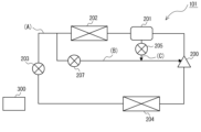
図1は、実施の形態1に係る冷凍サイクル装置の冷媒回路図である。図2は、実施の形態1に係る冷凍サイクル装置の構成要素であるスクロール圧縮機を示した概略縦断面図である。本実施の形態1に係る冷凍サイクル装置は、例えば、空気調和装置、冷凍装置、冷蔵庫、冷凍庫、自動販売機、または給湯装置等の用途に用いられる。冷凍サイクル装置は、図1に示すように、主回路Aと、冷媒インジェクション回路Bと、油インジェクション回路Cと、を有する冷媒回路100を備えている。
Embodiment 1.
FIG. 1 is a refrigerant circuit diagram of a refrigeration cycle apparatus according to Embodiment 1. FIG. FIG. 2 is a schematic longitudinal sectional view showing a scroll compressor that is a component of the refrigeration cycle apparatus according to Embodiment 1. FIG. The refrigerating cycle device according to Embodiment 1 is used for applications such as air conditioners, refrigerating devices, refrigerators, freezers, vending machines, and water heaters, for example. The refrigeration cycle device includes a refrigerant circuit 100 having a main circuit A, a refrigerant injection circuit B, and an oil injection circuit C, as shown in FIG.

主回路Aは、図1及び図2に示すように、冷媒を圧縮する圧縮室30及び圧縮室30に接続されるインジェクション配管12を有するスクロール圧縮機200と、油分離器201と、第1熱交換器202と、減圧装置203と、第2熱交換器204と、が順に配管で接続されて冷媒が循環する構成である。 The main circuit A, as shown in FIGS. The exchanger 202, the decompression device 203, and the second heat exchanger 204 are connected in order by pipes to circulate the refrigerant.

冷媒インジェクション回路Bは、図1及び図2に示すように、第1熱交換器202と減圧装置203との間の配管から分岐してスクロール圧縮機200のインジェクション配管12に接続された構成である。冷媒インジェクション回路Bには、冷媒インジェクション回路Bを流れる冷媒の流量を調整する第2制御弁207と、冷媒インジェクション回路Bを開閉する第2電磁弁208とが設けられている。第2制御弁207は、例えば電子膨張弁等で構成されている。なお、冷媒回路100は、第2制御弁207が0%~100%の開度調整が可能な構成であれば、第2電磁弁208を省略してもよい。 Refrigerant injection circuit B is, as shown in FIGS. . The refrigerant injection circuit B is provided with a second control valve 207 that adjusts the flow rate of refrigerant flowing through the refrigerant injection circuit B, and a second electromagnetic valve 208 that opens and closes the refrigerant injection circuit B. FIG. The second control valve 207 is composed of, for example, an electronic expansion valve. The refrigerant circuit 100 may omit the second electromagnetic valve 208 as long as the second control valve 207 can adjust the degree of opening from 0% to 100%.

油インジェクション回路Cは、図1及び図2に示すように、油分離器201から分岐し、第2熱交換器204に接続されたのち、冷媒インジェクション回路Bに接続され、該冷媒インジェクション回路Bを介してスクロール圧縮機200のインジェクション配管12に接続された構成である。油インジェクション回路Cには、第2熱交換器204と冷媒インジェクション回路Bの接続点との間において、油インジェクション回路Cを流れる油の流量を調整する第1制御弁205と、油インジェクション回路Cを開閉する第1電磁弁206とが設けられている。第1制御弁205は、例えば電子膨張弁等で構成されている。なお、冷媒回路100は、第1制御弁205が0%~100%の開度調整が可能な構成であれば、第1電磁弁206を省略してもよい。 As shown in FIGS. 1 and 2, the oil injection circuit C is branched from the oil separator 201, connected to the second heat exchanger 204, and then connected to the refrigerant injection circuit B. It is the structure connected to the injection pipe 12 of the scroll compressor 200 via. The oil injection circuit C includes a first control valve 205 that adjusts the flow rate of oil flowing through the oil injection circuit C between the second heat exchanger 204 and the connection point of the refrigerant injection circuit B, and the oil injection circuit C. A first electromagnetic valve 206 that opens and closes is provided. The first control valve 205 is composed of, for example, an electronic expansion valve. The refrigerant circuit 100 may omit the first solenoid valve 206 if the first control valve 205 is configured to be able to adjust the degree of opening from 0% to 100%.

次に、冷媒回路100を構成する各構成要素について説明する。先ず、図2に基づいて、スクロール圧縮機200の構成について説明する。 Next, each component constituting the refrigerant circuit 100 will be described. First, based on FIG. 2, the structure of the scroll compressor 200 is demonstrated.

スクロール圧縮機200は、冷媒回路100を循環する冷媒を吸入して圧縮し、高温高圧の状態として吐出させるものである。スクロール圧縮機200は、図2に示すように、外郭を形成するシェル1と、シェル1の内壁面に固着されたメインフレーム2と、冷媒を圧縮する圧縮室30を有する圧縮機構部3と、圧縮機構部3を駆動させる駆動機構部6と、圧縮機構部3と駆動機構部6を連結する主軸7と、を備えている。 The scroll compressor 200 sucks and compresses the refrigerant circulating in the refrigerant circuit 100, and discharges the refrigerant in a high-temperature, high-pressure state. As shown in FIG. 2, the scroll compressor 200 includes a shell 1 forming an outer shell, a main frame 2 fixed to the inner wall surface of the shell 1, a compression mechanism section 3 having a compression chamber 30 for compressing a refrigerant, A drive mechanism portion 6 that drives the compression mechanism portion 3 and a main shaft 7 that connects the compression mechanism portion 3 and the drive mechanism portion 6 are provided.

シェル1は、圧力容器で構成されている。シェル1には、外部からシェル1の内部に冷媒を取り込むための吸入管10と、圧縮した冷媒をシェル1から外部に吐き出す吐出管11と、が接続されている。吸入管10から吸入される冷媒の圧力は、低圧Psである。吐出管11から吐出される冷媒の圧力は、高圧Pdである。また、シェル1の内底部には、冷凍機油を貯留する油溜め14が設けられている。冷凍機油は、主軸7に形成された給油流路70を通って、圧縮機構部3及び各軸受等に供給される。 The shell 1 consists of a pressure vessel. The shell 1 is connected with a suction pipe 10 for taking refrigerant into the shell 1 from the outside and a discharge pipe 11 for discharging the compressed refrigerant from the shell 1 to the outside. The pressure of the refrigerant sucked from the suction pipe 10 is a low pressure Ps. The pressure of the refrigerant discharged from the discharge pipe 11 is high pressure Pd. An oil sump 14 for storing refrigerating machine oil is provided at the inner bottom of the shell 1 . Refrigerant oil is supplied to the compression mechanism portion 3 and each bearing through an oil supply passage 70 formed in the main shaft 7 .

圧縮機構部3は、固定スクロール4と揺動スクロール5とを備えている。固定スクロール4は、シェル1の内壁面に固着されているメインフレーム2にボルト等によって固定されている。固定スクロール4は、固定台板40と、固定台板40の下面に設けられたインボリュート曲線形状の突起である固定渦巻歯41と、を有している。揺動スクロール5は、揺動台板50と、揺動台板50の上面に設けられたインボリュート曲線形状の突起である揺動渦巻歯51と、を有している。 The compression mechanism section 3 includes a fixed scroll 4 and an orbiting scroll 5 . The fixed scroll 4 is fixed by bolts or the like to the main frame 2 fixed to the inner wall surface of the shell 1 . The fixed scroll 4 has a fixed base plate 40 and a fixed spiral tooth 41 which is an involute curve-shaped protrusion provided on the lower surface of the fixed base plate 40 . The oscillating scroll 5 has an oscillating base plate 50 and an oscillating spiral tooth 51 that is an involute curve-shaped protrusion provided on the upper surface of the oscillating base plate 50 .

固定スクロール4及び揺動スクロール5は、固定渦巻歯41と揺動渦巻歯51とを主軸7の回転中心に対して逆位相で噛み合わせた対称渦巻形状の状態でシェル1内に配置されている。圧縮機構部3には、固定スクロール4と揺動スクロール5とを固定渦巻歯41と揺動渦巻歯51とが噛み合うように組み合わせることで、固定渦巻歯41と揺動渦巻歯51との間に圧縮室30が形成されている。圧縮室30は、主軸7の回転に伴い、半径方向外側から内側へ向かうに従って容積が縮小するようになっている。 The fixed scroll 4 and the orbiting scroll 5 are arranged in the shell 1 in a symmetrical spiral shape in which the fixed spiral teeth 41 and the orbiting spiral teeth 51 are meshed in opposite phases with respect to the rotation center of the main shaft 7. . In the compression mechanism section 3, the fixed scroll 4 and the oscillating scroll 5 are combined so that the fixed spiral teeth 41 and the oscillating spiral teeth 51 are engaged with each other. A compression chamber 30 is formed. As the main shaft 7 rotates, the volume of the compression chamber 30 decreases from radially outward to radially inward.

また、固定台板40の中央部には、圧縮室30で圧縮されて高温かつ高圧となった冷媒を吐出する吐出ポート42が形成されている。固定スクロール4の上面には、吐出ポート42に連通する吐出流路15aが形成されたバックプレート15がボルト接合等で固定されて設けられている。バックプレート15には、冷媒の圧力に応じて吐出流路15aを開閉する吐出弁16がネジ止めして設けられている。吐出弁16は、吐出ポート42に連通する圧縮室30の冷媒が所定の圧力に達したときに、吐出流路15aを開状態にする。圧縮された高温かつ高圧冷媒は、吐出ポート42から固定スクロール4の上部の吐出空間13に排出され、吐出管11を通り、シェル1の外部へ吐出される。 A discharge port 42 is formed in the central portion of the fixed base plate 40 to discharge the high-temperature and high-pressure refrigerant compressed in the compression chamber 30 . A back plate 15 having a discharge passage 15a communicating with a discharge port 42 is provided on the upper surface of the fixed scroll 4 and fixed by bolting or the like. The back plate 15 is provided with a discharge valve 16 that opens and closes the discharge passage 15a according to the pressure of the refrigerant. The discharge valve 16 opens the discharge passage 15a when the refrigerant in the compression chamber 30 communicating with the discharge port 42 reaches a predetermined pressure. The compressed high-temperature and high-pressure refrigerant is discharged from the discharge port 42 into the discharge space 13 above the fixed scroll 4 , passes through the discharge pipe 11 , and is discharged to the outside of the shell 1 .

また、固定台板40には、圧縮室30に連通するインジェクション流路43が形成されている。インジェクション流路43は、主軸7の一回転中における圧縮行程の初期又は中間期において圧縮室30に連通する位置に形成されている。このときの圧縮室30の圧力は、低圧Psと高圧Pdとの間の中間圧となっている。また、バックプレート15には、インジェクション流路43に連通する連通流路15bが形成されている。バックプレート15には、シェル1の外部から連通流路15bに連通するインジェクション配管12が接続部材12aによって固定されている。つまり、インジェクション流路43は、連通流路15bを介してインジェクション配管12に接続されている。圧縮室30には、インジェクション配管12から連通流路15b及びインジェクション流路43を通って冷媒及び油が供給される。 An injection passage 43 communicating with the compression chamber 30 is formed in the fixed base plate 40 . The injection flow path 43 is formed at a position where it communicates with the compression chamber 30 at the initial stage or intermediate stage of the compression stroke during one rotation of the main shaft 7 . The pressure in the compression chamber 30 at this time is an intermediate pressure between the low pressure Ps and the high pressure Pd. Further, the back plate 15 is formed with a communication channel 15 b that communicates with the injection channel 43 . An injection pipe 12 communicating with the communication passage 15b from the outside of the shell 1 is fixed to the back plate 15 by a connecting member 12a. That is, the injection channel 43 is connected to the injection pipe 12 via the communication channel 15b. Refrigerant and oil are supplied from the injection pipe 12 to the compression chamber 30 through the communication channel 15 b and the injection channel 43 .

揺動スクロール5は、自転運動を阻止するためのオルダム継手8により、固定スクロール4に対して自転運動することなく公転運動を行う。なお、揺動台板50の揺動渦巻歯51が形成されていない側の面は、揺動スクロールスラスト軸受面として作用する。また、揺動スクロールスラスト軸受面の中心部には、中空円筒形状のボス部52が設けられている。ボス部52には、主軸7の一端に設けられた偏心軸部71が回転自在に連結されている。揺動スクロール5は、ボス部52に挿入された主軸7の偏心軸部71が回転することで、メインフレーム2のスラスト摺動面上で公転運動する。 The orbiting scroll 5 revolves around the fixed scroll 4 without rotating due to an Oldham's coupling 8 for preventing rotation. The surface of the rocking base plate 50 on which the rocking spiral teeth 51 are not formed acts as a rocking scroll thrust bearing surface. A hollow cylindrical boss portion 52 is provided at the center of the orbiting scroll thrust bearing surface. An eccentric shaft portion 71 provided at one end of the main shaft 7 is rotatably connected to the boss portion 52 . The orbiting scroll 5 revolves on the thrust sliding surface of the main frame 2 by rotating the eccentric shaft portion 71 of the main shaft 7 inserted into the boss portion 52 .

駆動機構部6は、メインフレーム2の下方に設けられ、主軸7を介して連結された揺動スクロール5を固定スクロール4に対して回転駆動させるものである。駆動機構部6は、シェル1の内壁面に焼き嵌め等により固定された円環状の固定子60と、固定子60の内側面に対向して回転自在に設けられた回転子61とで構成されている。固定子60は、例えば電磁鋼板を複数枚積層してなる鉄心に、絶縁層を介して巻線が巻回された構成である。回転子61は、電磁鋼板を複数枚積層してなる鉄心の内部に永久磁石が内蔵された構成であり、中央に上下方向に貫通する貫通孔を有している。回転子61の貫通孔には、主軸7が固定されている。駆動機構部6は、固定子60が通電されることで回転子61が回転し、該回転子61の回転に伴って主軸7が回転し、主軸7を介して連結された圧縮機構部3に駆動力が伝わる構成である。 The drive mechanism section 6 is provided below the main frame 2 and rotates the orbiting scroll 5 connected via the main shaft 7 with respect to the fixed scroll 4 . The driving mechanism 6 is composed of an annular stator 60 fixed to the inner wall surface of the shell 1 by shrink fitting or the like, and a rotor 61 rotatably provided facing the inner surface of the stator 60. ing. The stator 60 has a structure in which a winding is wound around an iron core formed by laminating a plurality of electromagnetic steel sheets, for example, with an insulating layer interposed therebetween. The rotor 61 has a structure in which a permanent magnet is built in an iron core formed by laminating a plurality of electromagnetic steel sheets, and has a through hole penetrating vertically in the center. A main shaft 7 is fixed to the through hole of the rotor 61 . In the drive mechanism section 6, the rotor 61 rotates when the stator 60 is energized, and the main shaft 7 rotates with the rotation of the rotor 61. It is a configuration in which the driving force is transmitted.

次に、スクロール圧縮機200以外の冷媒回路100の各構成要素について説明する。油分離器201は、スクロール圧縮機200の吐出側に接続されており、スクロール圧縮機200から吐出された冷媒ガスに含まれる油を分離するものである。油分離器201で冷媒ガスから分離された油は、油インジェクション回路Cを介してスクロール圧縮機200の吸入側に戻される。油分離器201で分離されなかった油は、第1熱交換器202、減圧装置203、第2熱交換器204を順に流れ、スクロール圧縮機200の吸入側に戻される。 Next, each component of the refrigerant circuit 100 other than the scroll compressor 200 will be described. The oil separator 201 is connected to the discharge side of the scroll compressor 200 and separates oil contained in refrigerant gas discharged from the scroll compressor 200 . The oil separated from the refrigerant gas by the oil separator 201 is returned to the suction side of the scroll compressor 200 via the oil injection circuit C. Oil that has not been separated by the oil separator 201 flows through the first heat exchanger 202 , the decompression device 203 and the second heat exchanger 204 in order, and is returned to the suction side of the scroll compressor 200 .

本実施の形態1における第1熱交換器202は、凝縮器として機能する。第1熱交換器202は、スクロール圧縮機200からの吐出冷媒と空気又は水等の熱媒体との間で熱交換を行なって冷媒を凝縮液化するものである。第1熱交換器202は、流入側が油分離器201に接続され、流出側が減圧装置203に接続されている。 The first heat exchanger 202 in Embodiment 1 functions as a condenser. The first heat exchanger 202 exchanges heat between the refrigerant discharged from the scroll compressor 200 and a heat medium such as air or water to condense and liquefy the refrigerant. The first heat exchanger 202 has an inflow side connected to the oil separator 201 and an outflow side connected to the decompression device 203 .

減圧装置203は、供給された冷媒を減圧して膨張させるものである。減圧装置203は、例えば膨張弁又はキャピラリーチューブ等で構成されている。 The decompression device 203 decompresses and expands the supplied refrigerant. The decompression device 203 is composed of, for example, an expansion valve or a capillary tube.

本実施の形態1における第2熱交換器204は、蒸発器として機能する。第2熱交換器204は、吸気口から吸引された空気と冷媒との間で熱交換を行うものであり、低圧の冷媒液(または気液二相冷媒)が流入し、空気と熱交換して冷媒を蒸発させるものである。第2熱交換器204は、流入側が減圧装置203に接続され、流出側がスクロール圧縮機200に接続されている。 The second heat exchanger 204 in Embodiment 1 functions as an evaporator. The second heat exchanger 204 exchanges heat between the air sucked from the intake port and the refrigerant. to evaporate the refrigerant. The second heat exchanger 204 has an inflow side connected to the pressure reducing device 203 and an outflow side connected to the scroll compressor 200 .

制御装置300は、冷凍サイクル装置の全体を制御するものである。制御装置300は、例えばスクロール圧縮機200の回転数制御、減圧装置203を構成する膨張弁の開度制御、第1制御弁205及び第2制御弁207の制御、第1電磁弁206及び第2電磁弁208の開閉動作等を行う。制御装置300は、マイクロコンピュータ等で構成され、CPU、RAM及びROM等を備えている。 The control device 300 controls the entire refrigeration cycle device. The control device 300 controls, for example, the rotation speed of the scroll compressor 200, the opening control of the expansion valves that constitute the pressure reducing device 203, the control of the first control valve 205 and the second control valve 207, the control of the first solenoid valve 206 and the second Opening and closing operations of the electromagnetic valve 208 are performed. The control device 300 is composed of a microcomputer or the like, and includes a CPU, a RAM, a ROM, and the like.

次に、本実施の形態1における冷媒回路100の冷媒の流れ及びインジェクション動作について説明する。主回路Aにおいて、スクロール圧縮機200から吐出された冷媒は、油分離器201で冷媒と油に分離されたのち、第1熱交換器202で冷却される。第1熱交換器202で冷却された冷媒は、減圧装置203で減圧された後、第2熱交換器204で加熱され、冷媒ガスとなる。第2熱交換器204から流出した冷媒ガスは、スクロール圧縮機200に戻る。 Next, the refrigerant flow and injection operation of the refrigerant circuit 100 according to Embodiment 1 will be described. In the main circuit A, the refrigerant discharged from the scroll compressor 200 is separated into refrigerant and oil by the oil separator 201 and then cooled by the first heat exchanger 202 . The refrigerant cooled by the first heat exchanger 202 is decompressed by the decompression device 203 and then heated by the second heat exchanger 204 to become refrigerant gas. Refrigerant gas that has flowed out of the second heat exchanger 204 returns to the scroll compressor 200 .

ここで、制御装置300は、冷媒インジェクショ動作時に、第1制御弁205及び第1電磁弁206を閉とし、第2制御弁207及び第2電磁弁208を開とする。これにより、第1熱交換器202で冷却された高圧の液冷媒の一部であるインジェクション冷媒は、冷媒インジェクション回路Bに流入し、第2制御弁207で減圧されて液状体又は二相状態となり、第2電磁弁208を介してスクロール圧縮機200のインジェクション配管12に流入する。インジェクション配管12に流入したインジェクション冷媒は、連通流路15b及びインジェクション流路43を通って圧縮途中過程の圧縮室30に流入する。このとき、油インジェクション回路Cの第1制御弁205及び第1電磁弁206は閉じているので、インジェクション配管12に油は流れない。 Here, the control device 300 closes the first control valve 205 and the first solenoid valve 206 and opens the second control valve 207 and the second solenoid valve 208 during the refrigerant injection operation. As a result, the injection refrigerant, which is part of the high-pressure liquid refrigerant cooled by the first heat exchanger 202, flows into the refrigerant injection circuit B, is decompressed by the second control valve 207, and becomes a liquid state or a two-phase state. , flows into the injection pipe 12 of the scroll compressor 200 via the second solenoid valve 208 . The injection refrigerant that has flowed into the injection pipe 12 flows through the communication flow path 15b and the injection flow path 43 into the compression chamber 30 during compression. At this time, since the first control valve 205 and the first electromagnetic valve 206 of the oil injection circuit C are closed, oil does not flow through the injection pipe 12 .

また、制御装置300は、油インジェクション動作時に、第1制御弁205及び第1電磁弁206を開とし、第2制御弁207及び第2電磁弁208を閉とする。これにより、スクロール圧縮機200から吐出され、油分離器201にて冷媒と油に分離された油の一部は、油インジェクション回路Cに流入し、第2熱交換器204によって冷却された高圧の油となったのち、第2制御弁207で減圧及び流量調整され、冷媒インジェクション回路Bの配管と接続されてスクロール圧縮機200のインジェクション配管12に流入する。インジェクション配管12に流入したインジェクション油は、連通流路15b及びインジェクション流路43を通って圧縮途中過程の圧縮室30に流入する。このとき、冷媒インジェクション回路Bの第2制御弁207及び第2電磁弁208は閉じられているので、インジェクション配管12に冷媒は流れない。 Further, the control device 300 opens the first control valve 205 and the first solenoid valve 206 and closes the second control valve 207 and the second solenoid valve 208 during the oil injection operation. As a result, part of the oil discharged from the scroll compressor 200 and separated into refrigerant and oil by the oil separator 201 flows into the oil injection circuit C and is cooled by the second heat exchanger 204. After becoming oil, the pressure is reduced and the flow rate is adjusted by the second control valve 207 , connected to the piping of the refrigerant injection circuit B, and flows into the injection piping 12 of the scroll compressor 200 . The injection oil that has flowed into the injection pipe 12 passes through the communication flow path 15b and the injection flow path 43 and flows into the compression chamber 30 during the compression process. At this time, since the second control valve 207 and the second electromagnetic valve 208 of the refrigerant injection circuit B are closed, the refrigerant does not flow through the injection pipe 12 .

そして、インジェクション流路43が圧縮途中過程の圧縮室30に連通したときの圧縮室30の内圧Pは、冷媒インジェクション回路B及び油インジェクション回路C中の内圧Pmよりも低い。これは、上述したように、インジェクション流路43が、主軸7の一回転中における圧縮行程の初期又は中間期において圧縮室30に連通する位置に形成されているためである。そして、圧縮室30の内圧Pと、冷媒インジェクション回路B及び油インジェクション回路C中の内圧Pmと、の差圧により、インジェクション配管12から連通流路15b及びインジェクション流路43にインジェクション冷媒又はインジェクション油が流入し、圧縮室30に供給される。これにより、圧縮途中過程のガス冷媒が冷却される。また、圧縮室30内に油が供給され、固定渦巻歯41と揺動渦巻歯51と間で油シールが行われる。 The internal pressure P of the compression chamber 30 when the injection passage 43 communicates with the compression chamber 30 during compression is lower than the internal pressure Pm in the refrigerant injection circuit B and the oil injection circuit C. This is because, as described above, the injection flow path 43 is formed at a position communicating with the compression chamber 30 at the initial or intermediate stage of the compression stroke during one rotation of the main shaft 7 . Due to the pressure difference between the internal pressure P of the compression chamber 30 and the internal pressure Pm of the refrigerant injection circuit B and the oil injection circuit C, the injection refrigerant or injection oil flows from the injection pipe 12 into the communication passage 15b and the injection passage 43. It flows in and is supplied to the compression chamber 30 . As a result, the gas refrigerant that is in the process of being compressed is cooled. In addition, oil is supplied into the compression chamber 30 to form an oil seal between the fixed spiral tooth 41 and the oscillating spiral tooth 51 .

以上のように、本実施の形態1の冷凍サイクル装置は、冷媒を圧縮する圧縮室30及び圧縮室30に接続されるインジェクション配管12を有するスクロール圧縮機200と、油分離器201と、第1熱交換器202と、減圧装置203と、第2熱交換器204と、が順に配管で接続され、冷媒が循環する主回路Aと、油分離器201から分岐してスクロール圧縮機200のインジェクション配管12に接続された油インジェクション回路Cと、冷凍サイクル装置を運転制御する制御装置300と、を備えている。油インジェクション回路Cには、制御装置300によって制御され、油インジェクション回路Cを流れる油の流量を調整する第1制御弁205が設けられている。 As described above, the refrigeration cycle apparatus of Embodiment 1 includes a scroll compressor 200 having a compression chamber 30 for compressing a refrigerant and an injection pipe 12 connected to the compression chamber 30, an oil separator 201, a first A heat exchanger 202, a decompression device 203, and a second heat exchanger 204 are connected in order by pipes, a main circuit A in which refrigerant circulates, and an injection pipe of the scroll compressor 200 branched from the oil separator 201. 12, and a control device 300 that controls the operation of the refrigeration cycle device. The oil injection circuit C is provided with a first control valve 205 that is controlled by the control device 300 and adjusts the flow rate of oil flowing through the oil injection circuit C. As shown in FIG.

よって、本実施の形態1の冷凍サイクル装置は、油インジェクション回路Cに油の流量を調整する第1制御弁205が設けられているので、圧縮室30にインジェクションする油の流量とタイミングを制御できる。よって、スクロール圧縮機200の運転周波数が高速域である状態において、圧縮室30に供給される油の量を調整することができるので、油圧縮による固定渦巻歯41及び揺動渦巻歯51の損傷を抑制でき、吐出油の循環量が増大することによる性能低下を抑制できる。 Therefore, in the refrigeration cycle apparatus of Embodiment 1, the oil injection circuit C is provided with the first control valve 205 for adjusting the flow rate of oil, so that the flow rate and timing of injection of oil into the compression chamber 30 can be controlled. . Therefore, in a state where the operating frequency of the scroll compressor 200 is in a high speed range, the amount of oil supplied to the compression chamber 30 can be adjusted. can be suppressed, and deterioration in performance due to an increase in the amount of discharged oil circulating can be suppressed.

油インジェクション回路Cは、油分離器201から分岐して第2熱交換器204を介してスクロール圧縮機200のインジェクション配管12に接続されている。よって、本実施の形態1の冷凍サイクル装置では、油分離器201で分離された油を第2熱交換器204で冷却してから圧縮室30にインジェクションすることができるので、圧縮室30内の冷媒ガスを冷却させることができ、吐出温度を抑制することができる。また、油を冷却させることで、粘度の高い油を圧縮室30にインジェクションすることができるので、固定渦巻歯41と揺動渦巻歯51の歯先同士のシール性が高くなり、冷媒の漏れ損失を減少させることができ、性能向上を図ることができる。 The oil injection circuit C is branched from the oil separator 201 and connected to the injection pipe 12 of the scroll compressor 200 via the second heat exchanger 204 . Therefore, in the refrigeration cycle apparatus of Embodiment 1, the oil separated by the oil separator 201 can be cooled by the second heat exchanger 204 and then injected into the compression chamber 30. The refrigerant gas can be cooled, and the discharge temperature can be suppressed. In addition, by cooling the oil, it is possible to inject oil with high viscosity into the compression chamber 30, so that the sealing performance between the tooth tips of the fixed spiral tooth 41 and the oscillating spiral tooth 51 is improved, resulting in refrigerant leakage loss. can be reduced and the performance can be improved.

本実施の形態1の冷凍サイクル装置は、第1熱交換器202と減圧装置203との間の配管から分岐して、スクロール圧縮機200のインジェクション配管12に接続された冷媒インジェクション回路Bを更に備えている。冷媒インジェクション回路Bには、制御装置300によって制御され、冷媒インジェクション回路Bを流れる冷媒の流量を制御する第2制御弁207が設けられている。よって、本実施の形態1の冷凍サイクル装置は、圧縮室30にインジェクションする冷媒の流量とタイミングを調整できるので、適量な冷媒を圧縮室30にインジェクションすることができ、スクロール圧縮機200の運転範囲の拡大及び使用する周波数範囲の拡大を図ることができる。 The refrigeration cycle apparatus of Embodiment 1 further includes a refrigerant injection circuit B branched from the pipe between the first heat exchanger 202 and the pressure reducing device 203 and connected to the injection pipe 12 of the scroll compressor 200. ing. Refrigerant injection circuit B is provided with a second control valve 207 that is controlled by control device 300 to control the flow rate of the refrigerant flowing through refrigerant injection circuit B. As shown in FIG. Therefore, the refrigeration cycle apparatus of Embodiment 1 can adjust the flow rate and timing of the refrigerant injected into the compression chambers 30, so that an appropriate amount of refrigerant can be injected into the compression chambers 30. can be expanded and the frequency range to be used can be expanded.

また、制御装置300は、冷媒インジェクション動作時に、第1制御弁205を閉とし、第2制御弁207を開とする制御を行い、油インジェクション動作時に、第1制御弁205を開とし、第2制御弁207を閉とする制御を行う。よって、本実施の形態1の冷凍サイクル装置は、圧縮機の高速運転時に、油インジェクション回路Cは閉とすることで、吐出油の循環量を抑制して性能向上を図ることができ、低速運転時に油インジェクションを行うことで、固定渦巻歯41及び揺動渦巻歯51間への油供給が可能となり、該固定渦巻歯41及び揺動渦巻歯51の摩耗を防止して信頼性の向上を図ることができる。 Further, the control device 300 performs control to close the first control valve 205 and open the second control valve 207 during the refrigerant injection operation, and to open the first control valve 205 and open the second control valve 207 during the oil injection operation. Control is performed to close the control valve 207 . Therefore, in the refrigeration cycle apparatus of Embodiment 1, the oil injection circuit C is closed during high-speed operation of the compressor, thereby suppressing the circulation amount of the discharged oil and improving the performance. By injecting oil from time to time, it becomes possible to supply oil between the fixed spiral tooth 41 and the oscillating spiral tooth 51, thereby preventing wear of the fixed spiral tooth 41 and the oscillating spiral tooth 51 and improving reliability. be able to.

実施の形態2.
次に、図3に基づいて本実施の形態2に係る冷凍サイクル装置を説明する。図3は、実施の形態2に係る冷凍サイクル装置の冷媒回路図である。なお、実施の形態1で説明した冷凍サイクル装置と同一の構成については、同一の符号を付して、その説明を適宜省略する。
Embodiment 2.
Next, a refrigeration cycle apparatus according to Embodiment 2 will be described with reference to FIG. FIG. 3 is a refrigerant circuit diagram of a refrigeration cycle apparatus according to Embodiment 2. FIG. The same reference numerals are given to the same configurations as those of the refrigeration cycle apparatus described in Embodiment 1, and the description thereof will be omitted as appropriate.

本実施の形態2に係る冷凍サイクル装置は、図3に示すように、主回路Aと、冷媒インジェクション回路Bと、油インジェクション回路Cと、を有する冷媒回路101を備えている。 The refrigeration cycle apparatus according to Embodiment 2 includes a refrigerant circuit 101 having a main circuit A, a refrigerant injection circuit B, and an oil injection circuit C, as shown in FIG.

主回路Aは、スクロール圧縮機200と、油分離器201と、第1熱交換器202と、減圧装置203と、第2熱交換器204と、が順に配管で接続され、冷媒が循環する構成である。本実施の形態2における第1熱交換器202は、凝縮器として機能する。また、本実施の形態2における第2熱交換器204は、蒸発器として機能する。 The main circuit A has a structure in which a scroll compressor 200, an oil separator 201, a first heat exchanger 202, a pressure reducing device 203, and a second heat exchanger 204 are connected in order by pipes, and the refrigerant circulates. is. The first heat exchanger 202 in Embodiment 2 functions as a condenser. Also, the second heat exchanger 204 in the second embodiment functions as an evaporator.

冷媒インジェクション回路Bは、第1熱交換器202と減圧装置203との間の配管から分岐してスクロール圧縮機200のインジェクション配管12に接続された構成である。冷媒インジェクション回路Bには、油インジェクション回路Cを流れる油の流量を調整する第2制御弁207が設けられている。第2制御弁207は、0%~100%の開度調整が可能な構成とされている。なお、実施の形態1に示すように、冷媒インジェクション回路Bに、該冷媒インジェクション回路Bを開閉させる第2電磁弁208を設けてもよい。 Refrigerant injection circuit B is configured to be branched from a pipe between first heat exchanger 202 and decompression device 203 and connected to injection pipe 12 of scroll compressor 200 . The refrigerant injection circuit B is provided with a second control valve 207 that adjusts the flow rate of oil flowing through the oil injection circuit C. As shown in FIG. The second control valve 207 is configured so that the degree of opening can be adjusted from 0% to 100%. In addition, as shown in Embodiment 1, the refrigerant injection circuit B may be provided with the second solenoid valve 208 for opening and closing the refrigerant injection circuit B. FIG.

油インジェクション回路Cは、油分離器201から分岐し、冷媒インジェクション回路Bにおける第2制御弁207とスクロール圧縮機200との間に接続され、該冷媒インジェクション回路Bを介してスクロール圧縮機200のインジェクション配管12に接続された構成である。油インジェクション回路Cには、油インジェクション回路Cを流れる油の流量を調整する第1制御弁205が設けられている。第1制御弁205は、0%~100%の開度調整が可能な構成とされている。なお、実施の形態1に示すように、油インジェクション回路Cに、該油インジェクション回路Cを開閉させる第1電磁弁206を設けてもよい。 The oil injection circuit C branches from the oil separator 201 and is connected between the second control valve 207 and the scroll compressor 200 in the refrigerant injection circuit B. Through the refrigerant injection circuit B, the scroll compressor 200 is injected. It is configured to be connected to the pipe 12 . The oil injection circuit C is provided with a first control valve 205 that adjusts the flow rate of oil flowing through the oil injection circuit C. As shown in FIG. The first control valve 205 is configured so that the degree of opening can be adjusted from 0% to 100%. Note that, as shown in Embodiment 1, the oil injection circuit C may be provided with the first solenoid valve 206 for opening and closing the oil injection circuit C.

以上のように、本実施の形態2の冷凍サイクル装置は、油インジェクション回路Cに油の流量を調整する第1制御弁205が設けられているので、圧縮室30にインジェクションする油の流量とタイミングを制御できる。よって、スクロール圧縮機200の運転周波数が高速域である状態において、圧縮室30に供給される油の量を調整することができるので、油圧縮による固定渦巻歯41及び揺動渦巻歯51の損傷を抑制でき、吐出油の循環量が増大することによる性能低下を抑制できる。 As described above, in the refrigeration cycle apparatus of Embodiment 2, the oil injection circuit C is provided with the first control valve 205 for adjusting the flow rate of oil. can be controlled. Therefore, in a state where the operating frequency of the scroll compressor 200 is in a high speed range, the amount of oil supplied to the compression chamber 30 can be adjusted. can be suppressed, and deterioration in performance due to an increase in the amount of discharged oil circulating can be suppressed.

また、本実施の形態2の冷凍サイクル装置は、圧縮室30にインジェクションする冷媒の流量とタイミングを調整できるので、適量な冷媒を圧縮室30にインジェクションすることができ、スクロール圧縮機200の運転範囲の拡大及び使用する周波数範囲の拡大を図ることができる。 In addition, since the refrigeration cycle apparatus of Embodiment 2 can adjust the flow rate and timing of the refrigerant injected into the compression chamber 30, an appropriate amount of refrigerant can be injected into the compression chamber 30. can be expanded and the frequency range to be used can be expanded.

また、本実施の形態2の冷凍サイクル装置は、圧縮機の高速運転時に、油インジェクション回路Cは閉とすることで、吐出油の循環量を抑制して性能向上を図ることができ、低速運転時に油インジェクションを行うことで、固定渦巻歯41及び揺動渦巻歯51間への油供給が可能となり、該固定渦巻歯41及び揺動渦巻歯51の摩耗を防止して信頼性の向上を図ることができる。 Further, in the refrigeration cycle apparatus of Embodiment 2, the oil injection circuit C is closed during high-speed operation of the compressor, so that the amount of discharged oil circulated can be suppressed and the performance can be improved. By injecting oil from time to time, it becomes possible to supply oil between the fixed spiral tooth 41 and the oscillating spiral tooth 51, thereby preventing wear of the fixed spiral tooth 41 and the oscillating spiral tooth 51 and improving reliability. be able to.

実施の形態3.
次に、図4に基づいて本実施の形態3に係る冷凍サイクル装置を説明する。図4は、実施の形態3に係る冷凍サイクル装置の冷媒回路図である。なお、実施の形態1及び2で説明した冷凍サイクル装置と同一の構成については、同一の符号を付して、その説明を適宜省略する。
Embodiment 3.
Next, a refrigeration cycle apparatus according to Embodiment 3 will be described with reference to FIG. 4 is a refrigerant circuit diagram of a refrigeration cycle apparatus according to Embodiment 3. FIG. The same reference numerals are given to the same configurations as those of the refrigeration cycle apparatuses described in Embodiments 1 and 2, and the description thereof will be omitted as appropriate.

本実施の形態3に係る冷凍サイクル装置の冷媒回路102は、実施の形態2の構成に加えて、油分離器201とスクロール圧縮機200の吸入側とをバイパスする返油管209を設けた構成を特徴としている。返油管209には、制御装置300によって制御され、返油管209を流れる油の流量を調整する第3制御弁210が設けられている。第3制御弁210は、0%~100%の開度調整が可能な電子膨張弁等で構成されている。なお、返油管209に、該返油管209を開閉させる電磁弁を設けてもよい。 Refrigerant circuit 102 of a refrigeration cycle apparatus according to Embodiment 3 has, in addition to the configuration of Embodiment 2, an oil return pipe 209 that bypasses oil separator 201 and the suction side of scroll compressor 200. Characterized by The oil return pipe 209 is provided with a third control valve 210 that is controlled by the control device 300 and adjusts the flow rate of oil flowing through the oil return pipe 209 . The third control valve 210 is composed of an electronic expansion valve or the like capable of adjusting the degree of opening from 0% to 100%. A solenoid valve for opening and closing the oil return pipe 209 may be provided in the oil return pipe 209 .

スクロール圧縮機200は、高速運転時において圧縮機構部3に供給される油の量は十分にある。そのため、インジェクション流路43に供給される油の量をゼロか、極端に少なくする。ただし、スクロール圧縮機200の高速運転時が続くと、油分離器201の内部に油が溜まる一方で、スクロール圧縮機200の油が枯渇するおそれがある。そのため、本実施の形態3の冷凍サイクル装置のように、油分離器201とスクロール圧縮機200の吸入側をバイパスする返油管209を設けると良い。さらに、返油管209に第3制御弁210を設けて、油分離器201の油の量に応じてスクロール圧縮機200の吸入側に返油してもよい。油分離器201内の油量は、油量計による油量の実測値から求める。なお、油分離器201内の油量は、スクロール圧縮機200の運転周波数とその運転時間から求めてもよい。また、油分離器201内の油量は、返油管209によりスクロール圧縮機200に戻された油の量から計算した推定値により求めてもよい。 Scroll compressor 200 has a sufficient amount of oil supplied to compression mechanism 3 during high-speed operation. Therefore, the amount of oil supplied to the injection flow path 43 is made zero or extremely small. However, if scroll compressor 200 continues to operate at high speed, oil may accumulate in oil separator 201 and oil in scroll compressor 200 may be depleted. Therefore, it is preferable to provide an oil return pipe 209 that bypasses the suction side of the oil separator 201 and the scroll compressor 200 as in the refrigeration cycle apparatus of the third embodiment. Furthermore, a third control valve 210 may be provided in the oil return pipe 209 to return oil to the suction side of the scroll compressor 200 according to the amount of oil in the oil separator 201 . The amount of oil in the oil separator 201 is obtained from the measured value of the amount of oil by an oil gauge. Note that the amount of oil in the oil separator 201 may be obtained from the operating frequency of the scroll compressor 200 and its operating time. Also, the amount of oil in the oil separator 201 may be obtained by an estimated value calculated from the amount of oil returned to the scroll compressor 200 through the oil return pipe 209 .

実施の形態4.
次に、図5に基づいて本実施の形態4に係る冷凍サイクル装置を説明する。図5は、実施の形態4に係る冷凍サイクル装置の冷媒回路図である。なお、実施の形態1~3で説明した冷凍サイクル装置と同一の構成については、同一の符号を付して、その説明を適宜省略する。
Embodiment 4.
Next, a refrigeration cycle apparatus according to Embodiment 4 will be described with reference to FIG. FIG. 5 is a refrigerant circuit diagram of a refrigeration cycle apparatus according to Embodiment 4. FIG. The same reference numerals are assigned to the same configurations as those of the refrigeration cycle apparatus described in the first to third embodiments, and the description thereof will be omitted as appropriate.

本実施の形態4に係る冷凍サイクル装置は、例えば冷暖房が可能な空気調和装置である。この冷凍サイクル装置は、図5に示すように、主回路Aと、冷媒インジェクション回路Bと、油インジェクション回路Cと、を有する冷媒回路103を備えている。 A refrigeration cycle apparatus according to Embodiment 4 is, for example, an air conditioner capable of cooling and heating. This refrigeration cycle apparatus includes a refrigerant circuit 103 having a main circuit A, a refrigerant injection circuit B, and an oil injection circuit C, as shown in FIG.

主回路Aは、スクロール圧縮機200と、油分離器201と、流路切換手段211と、第1熱交換器202と、第1減圧装置212と、第2減圧装置213、第2熱交換器204と、が順に配管で接続され、冷媒が循環する構成である。 The main circuit A includes a scroll compressor 200, an oil separator 201, a flow path switching means 211, a first heat exchanger 202, a first pressure reducing device 212, a second pressure reducing device 213, and a second heat exchanger. 204 and are connected in order by pipes, and the refrigerant circulates.

流路切換手段211は、例えば四方弁であり、制御装置300によって制御されて冷媒の流路を切り換える機能を有するものである。流路切換手段211は、冷房運転時において、図5の実線で示すように、スクロール圧縮機200の吐出側と第1熱交換器202とを接続するとともに、スクロール圧縮機200の吸入側と第2熱交換器204とを接続するように冷媒流路を切り換える。流路切換手段211は、暖房運転時において、図5の破線で示すように、スクロール圧縮機200の吐出側と第2熱交換器204とを接続するとともに、スクロール圧縮機200の吸入側と第1熱交換器202とを接続するように冷媒流路を切り換える。なお、流路切換手段211は、二方弁又は三方弁を組み合わせて構成してもよい。 The channel switching means 211 is, for example, a four-way valve, and has a function of switching the coolant channel under control of the control device 300 . During cooling operation, the flow path switching means 211 connects the discharge side of the scroll compressor 200 and the first heat exchanger 202, and connects the suction side of the scroll compressor 200 and the first heat exchanger 202, as indicated by the solid line in FIG. 2 switch the refrigerant flow path so as to connect with the heat exchanger 204 . During heating operation, the flow path switching means 211 connects the discharge side of the scroll compressor 200 and the second heat exchanger 204, and connects the suction side of the scroll compressor 200 and the second heat exchanger 204, as indicated by the dashed line in FIG. 1 switch the refrigerant flow path so as to connect with the heat exchanger 202 . The channel switching means 211 may be configured by combining two-way valves or three-way valves.

第1熱交換器202は、冷房運転時に凝縮器として機能して冷媒を液化し、暖房運転時に蒸発器として機能して冷媒を気化させる構成である。第2熱交換器204は、冷房運転時に蒸発器として機能し、暖房運転時に凝縮器として機能する。 The first heat exchanger 202 functions as a condenser to liquefy the refrigerant during cooling operation, and functions as an evaporator to evaporate the refrigerant during heating operation. The second heat exchanger 204 functions as an evaporator during cooling operation, and functions as a condenser during heating operation.

第1減圧装置212及び第2減圧装置213は、制御装置300によって制御され、供給された冷媒を減圧して膨張させるものである。第1減圧装置212及び第2減圧装置213は、例えば膨張弁又はキャピラリーチューブ等で構成されている。 The first decompression device 212 and the second decompression device 213 are controlled by the control device 300 to decompress and expand the supplied refrigerant. The first decompression device 212 and the second decompression device 213 are configured by, for example, expansion valves or capillary tubes.

冷媒インジェクション回路Bは、第1減圧装置212と第2減圧装置213との間の配管から分岐してスクロール圧縮機200のインジェクション配管12に接続された構成である。冷媒インジェクション回路Bには、冷媒インジェクション回路Bを流れる冷媒の流量を調整する第2制御弁207が設けられている。第2制御弁207は、0%~100%の開度調整が可能な構成とされている。なお、実施の形態1に示すように、冷媒インジェクション回路Bに、該冷媒インジェクション回路Bを開閉させる第2電磁弁208を設けてもよい。 Refrigerant injection circuit B is configured to branch from a pipe between first pressure reducing device 212 and second pressure reducing device 213 and to be connected to injection pipe 12 of scroll compressor 200 . The refrigerant injection circuit B is provided with a second control valve 207 that adjusts the flow rate of the refrigerant flowing through the refrigerant injection circuit B. As shown in FIG. The second control valve 207 is configured so that the degree of opening can be adjusted from 0% to 100%. In addition, as shown in Embodiment 1, the refrigerant injection circuit B may be provided with the second solenoid valve 208 for opening and closing the refrigerant injection circuit B. FIG.

油インジェクション回路Cは、油分離器201から分岐し、冷媒インジェクション回路Bにおける第2制御弁207とスクロール圧縮機200との間に接続され、該冷媒インジェクション回路Bを介してスクロール圧縮機200のインジェクション配管12に接続された構成である。油インジェクション回路Cには、油インジェクション回路Cを流れる油の流量を調整する第1制御弁205が設けられている。第1制御弁205は、0%~100%の開度調整が可能な構成とされている。なお、実施の形態1に示すように、油インジェクション回路C、該油インジェクション回路Cを開閉させる第1電磁弁206を設けてもよい。 The oil injection circuit C branches from the oil separator 201 and is connected between the second control valve 207 and the scroll compressor 200 in the refrigerant injection circuit B. Through the refrigerant injection circuit B, the scroll compressor 200 is injected. It is configured to be connected to the pipe 12 . The oil injection circuit C is provided with a first control valve 205 that adjusts the flow rate of oil flowing through the oil injection circuit C. As shown in FIG. The first control valve 205 is configured so that the degree of opening can be adjusted from 0% to 100%. Note that, as shown in Embodiment 1, the oil injection circuit C and the first electromagnetic valve 206 for opening and closing the oil injection circuit C may be provided.

また、本実施の形態4における冷媒回路103には、油分離器201とスクロール圧縮機200の吸入側とをバイパスする返油管209が設けられている。返油管209には、制御装置300によって制御され、返油管209を流れる油の流量を調整する第3制御弁210が設けられている。第3制御弁210は、0%~100%の開度調整が可能な電子膨張弁等で構成されている。なお、図示することは省略したが、返油管209に、該返油管209を開閉させる電磁弁を設けてもよい。 Refrigerant circuit 103 in Embodiment 4 is provided with oil return pipe 209 that bypasses oil separator 201 and the suction side of scroll compressor 200 . The oil return pipe 209 is provided with a third control valve 210 that is controlled by the control device 300 and adjusts the flow rate of oil flowing through the oil return pipe 209 . The third control valve 210 is composed of an electronic expansion valve or the like capable of adjusting the degree of opening from 0% to 100%. Although not shown, the oil return pipe 209 may be provided with an electromagnetic valve for opening and closing the oil return pipe 209 .

以上のように、本実施の形態4に係る冷凍サイクル装置においても、上記実施の形態2及び3に記載した作用効果と同様の作用効果を得ることができる。 As described above, also in the refrigeration cycle apparatus according to the fourth embodiment, the same effects as those described in the second and third embodiments can be obtained.

実施の形態5.
次に、図6に基づいて本実施の形態5に係る冷凍サイクル装置を説明する。図6は、実施の形態5に係る冷凍サイクル装置の冷媒回路図である。なお、実施の形態1~4で説明した冷凍サイクル装置と同一の構成については、同一の符号を付して、その説明を適宜省略する。
Embodiment 5.
Next, a refrigeration cycle apparatus according to Embodiment 5 will be described with reference to FIG. 6 is a refrigerant circuit diagram of a refrigeration cycle apparatus according to Embodiment 5. FIG. The same reference numerals are assigned to the same configurations as those of the refrigeration cycle apparatus described in the first to fourth embodiments, and the description thereof will be omitted as appropriate.

本実施の形態5に係る冷凍サイクル装置は、図6に示すように、上述した実施の形態4の冷凍サイクル装置と比して、油インジェクション回路Cの構成が異なる。そのため、本実施の形態5では、油インジェクション回路Cの構成のみを説明し、その他の構成については実施の形態4の構成を援用する。 As shown in FIG. 6, the refrigerating cycle device according to Embodiment 5 differs from the refrigerating cycle device according to Embodiment 4 described above in the configuration of the oil injection circuit C. As shown in FIG. Therefore, in the fifth embodiment, only the configuration of the oil injection circuit C will be described, and the configuration of the fourth embodiment is used for other configurations.

本実施の形態5における油インジェクション回路Cは、第1油インジェクション回路C1と、第2油インジェクション回路C2と、を有している。 The oil injection circuit C in Embodiment 5 has a first oil injection circuit C1 and a second oil injection circuit C2.

第1油インジェクション回路C1は、図6に示すように、油分離器201から分岐し、第1熱交換器202に接続されたのち、冷媒インジェクション回路Bに接続され、該冷媒インジェクション回路Bを介して、図2に示すスクロール圧縮機200のインジェクション配管12に接続された構成である。第1油インジェクション回路C1における油分離器201と第1熱交換器202との間には、制御装置300によって制御され、第1油インジェクション回路C1を流れる油の流量を調整する第1制御弁205が設けられている。第1制御弁205は、0%~100%の開度調整が可能な電子膨張弁等で構成されている。なお、第1油インジェクション回路C1に、該第1油インジェクション回路C1を開閉させる電磁弁を設けてもよい。 As shown in FIG. 6, the first oil injection circuit C1 is branched from the oil separator 201, connected to the first heat exchanger 202, and then connected to the refrigerant injection circuit B. , and connected to the injection pipe 12 of the scroll compressor 200 shown in FIG. Between the oil separator 201 and the first heat exchanger 202 in the first oil injection circuit C1, a first control valve 205 that is controlled by the control device 300 and adjusts the flow rate of oil flowing through the first oil injection circuit C1. is provided. The first control valve 205 is composed of an electronic expansion valve or the like capable of adjusting the degree of opening from 0% to 100%. A solenoid valve for opening and closing the first oil injection circuit C1 may be provided in the first oil injection circuit C1.

第2油インジェクション回路C2は、図6に示すように、油分離器201から分岐し、第2熱交換器204に接続されたのち、冷媒インジェクション回路Bに接続され、該冷媒インジェクション回路Bを介して、図2に示すスクロール圧縮機200のインジェクション配管12に接続された構成である。第2油インジェクション回路C2における油分離器201と第2熱交換器204との間には、制御装置300によって制御され、第2油インジェクション回路C2を流れる油の流量を調整する第1制御弁205が設けられている。第1制御弁205は、0%~100%の開度調整が可能な電子膨張弁等で構成されている。なお、第2油インジェクション回路C2に、該第2油インジェクション回路C2を開閉させる電磁弁を設けてもよい。 As shown in FIG. 6, the second oil injection circuit C2 is branched from the oil separator 201, connected to the second heat exchanger 204, and then connected to the refrigerant injection circuit B. , and connected to the injection pipe 12 of the scroll compressor 200 shown in FIG. Between the oil separator 201 and the second heat exchanger 204 in the second oil injection circuit C2, a first control valve 205 that is controlled by the control device 300 and adjusts the flow rate of oil flowing through the second oil injection circuit C2. is provided. The first control valve 205 is composed of an electronic expansion valve or the like capable of adjusting the degree of opening from 0% to 100%. A solenoid valve for opening and closing the second oil injection circuit C2 may be provided in the second oil injection circuit C2.

本実施の形態5の冷媒回路104では、第1熱交換器202が蒸発器として機能する場合、第1油インジェクション回路C1を通じてインジェクション配管12から圧縮室30に油が供給され、第2熱交換器204が蒸発器として機能する場合、第2油インジェクション回路C2と通じてインジェクション配管12から圧縮室30に油が供給される。 In the refrigerant circuit 104 of Embodiment 5, when the first heat exchanger 202 functions as an evaporator, oil is supplied from the injection pipe 12 to the compression chamber 30 through the first oil injection circuit C1, and the second heat exchanger When 204 functions as an evaporator, oil is supplied from the injection pipe 12 to the compression chamber 30 through the second oil injection circuit C2.

以上のように、本実施の形態5に係る冷凍サイクル装置においても、上記実施の形態1で説明した作用効果と同様の作用効果を得ることができる。 As described above, also in the refrigeration cycle apparatus according to the fifth embodiment, it is possible to obtain the same effects as those described in the first embodiment.

以上に、冷凍サイクル装置を実施の形態に基づいて説明したが、冷凍サイクル装置は上述した実施の形態の構成に限定されるものではない。冷凍サイクル装置は、上述した構成要素に限定されるものではなく、他の構成要素を含んでもよいし、一部構成要素を省略してもよい。例えば、冷媒インジェクション回路Bは必ずしも設ける必要はなく、省略してもよい。また、油分離器201は、凝縮器と減圧装置との間、又は減圧装置と冷媒インジェクション回路Bの分岐点との間に設けてもよい。この場合、冷凍サイクルによる冷媒の温度が低下することに伴い、油の温度も低下させることができる。また、上記圧力の高低については、特に絶対的な値との関係で定まっているものではなく、システム及び装置等における状態及び動作等において相対的に定まるものである。要するに、冷凍サイクル装置は、その技術的思想を逸脱しない範囲において、当業者が通常に行う設計変更及び応用のバリエーションの範囲を含むものである。 Although the refrigeration cycle apparatus has been described above based on the embodiment, the refrigeration cycle apparatus is not limited to the configuration of the embodiment described above. The refrigeration cycle device is not limited to the components described above, and may include other components or omit some components. For example, the coolant injection circuit B is not necessarily provided and may be omitted. Also, the oil separator 201 may be provided between the condenser and the decompression device, or between the decompression device and the branch point of the refrigerant injection circuit B. In this case, the temperature of the oil can also be lowered as the temperature of the refrigerant is lowered by the refrigeration cycle. Moreover, the magnitude of the pressure is not determined by the relationship with the absolute value, but relatively determined by the state and operation of the system and device. In short, the refrigeration cycle apparatus includes a range of design changes and application variations that are normally made by those skilled in the art within a range that does not deviate from the technical idea thereof.

1 シェル、2 メインフレーム、3 圧縮機構部、4 固定スクロール、5 揺動スクロール、6 駆動機構部、7 主軸、8 オルダム継手、10 吸入管、11 吐出管、12 インジェクション配管、12a 接続部材、13 吐出空間、14 油溜め、15 バックプレート、15a 吐出流路、15b 連通流路、16 吐出弁、30 圧縮室、40 固定台板、41 固定渦巻歯、42 吐出ポート、43 インジェクション流路、50 揺動台板、51 揺動渦巻歯、52 ボス部、60 固定子、61 回転子、70 給油流路、71 偏心軸部、100、101、102、103 冷媒回路、200
スクロール圧縮機、201 油分離器、202 第1熱交換器、203 減圧装置、204 第2熱交換器、205 第1制御弁、206 第1電磁弁、207 第2制御弁、208 第2電磁弁、209 返油管、210 第3制御弁、211 流路切換手段、212 第1減圧装置、213 第2減圧装置、300 制御装置、A 主回路、B 冷媒インジェクション回路、C 油インジェクション回路、C1 第1油インジェクション回路、第2油インジェクション回路。
Reference Signs List 1 Shell 2 Main Frame 3 Compression Mechanism Part 4 Fixed Scroll 5 Oscillating Scroll 6 Drive Mechanism Part 7 Main Shaft 8 Oldham Coupling 10 Suction Pipe 11 Discharge Pipe 12 Injection Pipe 12a Connection Member 13 Discharge space 14 Oil reservoir 15 Back plate 15a Discharge channel 15b Communication channel 16 Discharge valve 30 Compression chamber 40 Fixed base plate 41 Fixed spiral tooth 42 Discharge port 43 Injection channel 50 Fluctuation 100, 101, 102, 103 Refrigerant circuit 200
scroll compressor 201 oil separator 202 first heat exchanger 203 decompression device 204 second heat exchanger 205 first control valve 206 first solenoid valve 207 second control valve 208 second solenoid valve , 209 oil return pipe, 210 third control valve, 211 flow path switching means, 212 first pressure reducing device, 213 second pressure reducing device, 300 control device, A main circuit, B refrigerant injection circuit, C oil injection circuit, C1 first first Oil injection circuit, second oil injection circuit.

Claims (4)

冷媒を圧縮する圧縮室及び前記圧縮室に接続されるインジェクション配管を有するスクロール圧縮機と、油分離器と、第1熱交換器と、減圧装置と、第2熱交換器と、が順に配管で接続され、冷媒が循環する主回路と、
前記油分離器から分岐して前記スクロール圧縮機の前記インジェクション配管に接続された油インジェクション回路と、
冷凍サイクル装置を運転制御する制御装置と、を備え、
前記油インジェクション回路は、
前記油分離器から分岐し、前記第1熱交換器を介して前記スクロール圧縮機の前記インジェクション配管に接続された第1油インジェクション回路と、
前記油分離器から分岐し、前記第2熱交換器を介して前記スクロール圧縮機の前記インジェクション配管に接続された第2油インジェクション回路と、を有し、
前記第1油インジェクション回路及び前記第2油インジェクション回路には、前記制御装置によって制御され、前記油インジェクション回路を流れる油の流量を調整する第1制御弁がそれぞれ設けられており、
前記制御装置は、前記スクロール圧縮機の高速運転時に前記第1制御弁を閉とし、前記スクロール圧縮機の低速運転時に前記第1制御弁を開とする制御を行って油インジェクションを行う、冷凍サイクル装置。
A scroll compressor having a compression chamber for compressing a refrigerant and an injection pipe connected to the compression chamber, an oil separator, a first heat exchanger, a decompression device, and a second heat exchanger are connected in order by pipes. a main circuit connected and through which a refrigerant circulates;
an oil injection circuit branched from the oil separator and connected to the injection pipe of the scroll compressor;
and a control device that controls the operation of the refrigeration cycle device,
The oil injection circuit is
a first oil injection circuit branched from the oil separator and connected to the injection pipe of the scroll compressor via the first heat exchanger;
a second oil injection circuit branched from the oil separator and connected to the injection pipe of the scroll compressor via the second heat exchanger;
The first oil injection circuit and the second oil injection circuit are each provided with a first control valve that is controlled by the control device and adjusts the flow rate of oil flowing through the oil injection circuit,
The control device closes the first control valve during high-speed operation of the scroll compressor and opens the first control valve during low-speed operation of the scroll compressor to perform oil injection. Device.
前記第1熱交換器と前記減圧装置との間の配管から分岐して、前記スクロール圧縮機の前記インジェクション配管に接続された冷媒インジェクション回路を更に備え、
前記冷媒インジェクション回路には、前記制御装置によって制御され、前記冷媒インジェクション回路を流れる冷媒の流量を調整する第2制御弁が設けられている、請求項1に記載の冷凍サイクル装置。
further comprising a refrigerant injection circuit branched from a pipe between the first heat exchanger and the decompression device and connected to the injection pipe of the scroll compressor,
2. The refrigeration cycle apparatus according to claim 1 , wherein said refrigerant injection circuit is provided with a second control valve that is controlled by said controller and adjusts the flow rate of refrigerant flowing through said refrigerant injection circuit.
前記制御装置は、
冷媒インジェクション動作時に、前記第1制御弁を閉とし、前記第2制御弁を開とする制御を行い、
油インジェクション動作時に、前記第1制御弁を開とし、前記第2制御弁を閉とする制御を行う、請求項に記載の冷凍サイクル装置。
The control device is
performing control to close the first control valve and open the second control valve during the refrigerant injection operation;
3. The refrigeration cycle apparatus according to claim 2 , wherein control is performed to open said first control valve and to close said second control valve during an oil injection operation.
前記油分離器と前記スクロール圧縮機の吸入側とを接続する返油管を更に備え、
前記返油管には、前記制御装置によって制御され、前記返油管を流れる油の流量を調整する第3制御弁が設けられている、請求項1~のいずれか一項に記載の冷凍サイクル装置。
further comprising an oil return pipe connecting the oil separator and the suction side of the scroll compressor,
The refrigeration cycle apparatus according to any one of claims 1 to 3 , wherein the oil return pipe is provided with a third control valve that is controlled by the control device and adjusts the flow rate of oil flowing through the oil return pipe. .
JP2021569632A 2020-01-07 2020-01-07 refrigeration cycle equipment Active JP7292428B2 (en)

Applications Claiming Priority (1)

Application Number Priority Date Filing Date Title
PCT/JP2020/000169 WO2021140566A1 (en) 2020-01-07 2020-01-07 Refrigeration cycle device

Publications (3)

Publication Number Publication Date
JPWO2021140566A1 JPWO2021140566A1 (en) 2021-07-15
JPWO2021140566A5 JPWO2021140566A5 (en) 2022-04-21
JP7292428B2 true JP7292428B2 (en) 2023-06-16

Family

ID=76788530

Family Applications (1)

Application Number Title Priority Date Filing Date
JP2021569632A Active JP7292428B2 (en) 2020-01-07 2020-01-07 refrigeration cycle equipment

Country Status (3)

Country Link
JP (1) JP7292428B2 (en)
CN (1) CN114846283B (en)
WO (1) WO2021140566A1 (en)

Families Citing this family (1)

* Cited by examiner, † Cited by third party
Publication number Priority date Publication date Assignee Title
GB2615111A (en) * 2022-01-28 2023-08-02 Agilent Technologies Inc Cooling arrangements for analytical device

Citations (4)

* Cited by examiner, † Cited by third party
Publication number Priority date Publication date Assignee Title
JP2000274890A (en) 1999-03-18 2000-10-06 Nippon Soken Inc Supercritical cycle
JP2005273928A (en) 2004-03-23 2005-10-06 Mitsubishi Electric Corp Refrigerant circuit
WO2019021360A1 (en) 2017-07-25 2019-01-31 三菱電機株式会社 Refrigeration cycle device
JP2019039620A (en) 2017-08-25 2019-03-14 東芝キヤリア株式会社 Refrigeration cycle device

Family Cites Families (12)

* Cited by examiner, † Cited by third party
Publication number Priority date Publication date Assignee Title
JPS5529011Y2 (en) * 1975-03-18 1980-07-10
JPH0178863U (en) * 1987-11-18 1989-05-26
JP2000018738A (en) * 1998-06-23 2000-01-18 Kobe Steel Ltd Refrigeration device
JP2000046420A (en) * 1998-07-31 2000-02-18 Zexel Corp Refrigeration cycle
JP2000249412A (en) * 1999-03-01 2000-09-14 Sanyo Electric Co Ltd Refrigeration unit
JP2003148814A (en) * 2001-11-15 2003-05-21 Matsushita Electric Ind Co Ltd Refrigerating machine
JP2008101559A (en) * 2006-10-20 2008-05-01 Hitachi Appliances Inc Scroll compressor and refrigeration cycle using the same
JP4963971B2 (en) * 2007-01-15 2012-06-27 三菱電機株式会社 Heat pump type equipment
CN105917178B (en) * 2014-05-15 2018-02-02 三菱电机株式会社 Refrigerating plant
JP6472510B2 (en) * 2015-04-24 2019-02-20 三菱電機株式会社 Refrigeration air conditioner
US11248604B2 (en) * 2017-06-06 2022-02-15 Mitsubishi Electric Corporation Scroll compressor and refrigeration cycle apparatus
JP6956791B2 (en) * 2017-08-04 2021-11-02 三菱電機株式会社 Refrigeration cycle device and heat source unit

Patent Citations (4)

* Cited by examiner, † Cited by third party
Publication number Priority date Publication date Assignee Title
JP2000274890A (en) 1999-03-18 2000-10-06 Nippon Soken Inc Supercritical cycle
JP2005273928A (en) 2004-03-23 2005-10-06 Mitsubishi Electric Corp Refrigerant circuit
WO2019021360A1 (en) 2017-07-25 2019-01-31 三菱電機株式会社 Refrigeration cycle device
JP2019039620A (en) 2017-08-25 2019-03-14 東芝キヤリア株式会社 Refrigeration cycle device

Also Published As

Publication number Publication date
CN114846283B (en) 2024-01-16
WO2021140566A1 (en) 2021-07-15
JPWO2021140566A1 (en) 2021-07-15
CN114846283A (en) 2022-08-02

Similar Documents

Publication Publication Date Title
JP4859694B2 (en) Multistage compressor
KR101280155B1 (en) Heat pump device, two-stage compressor, and method of operating heat pump device
JP4875484B2 (en) Multistage compressor
EP2565555A1 (en) Refrigeration cycle device
JP2009127902A (en) Refrigerating device and compressor
EP2015003B1 (en) Refrigerating apparatus
KR20040020013A (en) Refrigerant cycling device and compressor using the same
KR20030044867A (en) Multi-stage compression type rotary compressor manufacturing method
JP2012137207A (en) Refrigerating cycle apparatus
WO2018096825A1 (en) Compressor having injection function
JP6253278B2 (en) Refrigeration cycle
WO2018096823A1 (en) Asymmetrical scroll compressor
WO2018096824A1 (en) Scroll compressor
US20220010796A1 (en) Rotary compressor and refrigeration cycle device
KR20040111018A (en) Refrigerant cycle apparatus
JP7292428B2 (en) refrigeration cycle equipment
JPWO2018198164A1 (en) Air conditioner
JP2017194064A (en) Refrigeration cycle
JP2009186030A (en) Turbo refrigerator
WO2019021360A1 (en) Refrigeration cycle device
WO2015104822A1 (en) Refrigeration cycle device
CA3137384C (en) Rotary compressor and refrigeration cycle device
US10436202B2 (en) Scroll compressor and refrigeration cycle apparatus
WO2022185365A1 (en) Scroll compressor and refrigeration cycle device
JP4952599B2 (en) Turbo refrigerator

Legal Events

Date Code Title Description
A521 Request for written amendment filed

Free format text: JAPANESE INTERMEDIATE CODE: A523

Effective date: 20220203

A621 Written request for application examination

Free format text: JAPANESE INTERMEDIATE CODE: A621

Effective date: 20220203

A131 Notification of reasons for refusal

Free format text: JAPANESE INTERMEDIATE CODE: A131

Effective date: 20230110

A521 Request for written amendment filed

Free format text: JAPANESE INTERMEDIATE CODE: A523

Effective date: 20230217

TRDD Decision of grant or rejection written
A01 Written decision to grant a patent or to grant a registration (utility model)

Free format text: JAPANESE INTERMEDIATE CODE: A01

Effective date: 20230509

A61 First payment of annual fees (during grant procedure)

Free format text: JAPANESE INTERMEDIATE CODE: A61

Effective date: 20230606

R150 Certificate of patent or registration of utility model

Ref document number: 7292428

Country of ref document: JP

Free format text: JAPANESE INTERMEDIATE CODE: R150