WO2019017456A1 - 電池用包装材料、電池用包装材料の製造方法、及び電池 - Google Patents
電池用包装材料、電池用包装材料の製造方法、及び電池 Download PDFInfo
- Publication number
- WO2019017456A1 WO2019017456A1 PCT/JP2018/027187 JP2018027187W WO2019017456A1 WO 2019017456 A1 WO2019017456 A1 WO 2019017456A1 JP 2018027187 W JP2018027187 W JP 2018027187W WO 2019017456 A1 WO2019017456 A1 WO 2019017456A1
- Authority
- WO
- WIPO (PCT)
- Prior art keywords
- layer
- packaging material
- acid
- resin
- barrier layer
- Prior art date
Links
- 239000005022 packaging material Substances 0.000 title claims abstract description 144
- 238000004519 manufacturing process Methods 0.000 title claims description 14
- 238000000034 method Methods 0.000 title description 44
- 230000004888 barrier function Effects 0.000 claims abstract description 156
- 239000002253 acid Substances 0.000 claims abstract description 135
- 229920005989 resin Polymers 0.000 claims abstract description 135
- 239000011347 resin Substances 0.000 claims abstract description 135
- 229910020197 CePO4 Inorganic materials 0.000 claims abstract description 55
- 238000005011 time of flight secondary ion mass spectroscopy Methods 0.000 claims abstract description 21
- 238000002042 time-of-flight secondary ion mass spectrometry Methods 0.000 claims abstract description 21
- 239000010410 layer Substances 0.000 claims description 352
- 239000012790 adhesive layer Substances 0.000 claims description 102
- -1 polypropylene Polymers 0.000 claims description 77
- 229920000098 polyolefin Polymers 0.000 claims description 56
- 238000000576 coating method Methods 0.000 claims description 51
- 239000011248 coating agent Substances 0.000 claims description 42
- 239000003795 chemical substances by application Substances 0.000 claims description 41
- 239000000463 material Substances 0.000 claims description 41
- 239000004743 Polypropylene Substances 0.000 claims description 34
- 229920001155 polypropylene Polymers 0.000 claims description 34
- 150000001875 compounds Chemical class 0.000 claims description 32
- 238000010030 laminating Methods 0.000 claims description 24
- 239000011888 foil Substances 0.000 claims description 21
- 229910052782 aluminium Inorganic materials 0.000 claims description 20
- XAGFODPZIPBFFR-UHFFFAOYSA-N aluminium Chemical compound [Al] XAGFODPZIPBFFR-UHFFFAOYSA-N 0.000 claims description 20
- 239000003822 epoxy resin Substances 0.000 claims description 20
- 229920000647 polyepoxide Polymers 0.000 claims description 20
- 125000003504 2-oxazolinyl group Chemical group O1C(=NCC1)* 0.000 claims description 18
- 239000011342 resin composition Substances 0.000 claims description 18
- IQPQWNKOIGAROB-UHFFFAOYSA-N isocyanate group Chemical group [N-]=C=O IQPQWNKOIGAROB-UHFFFAOYSA-N 0.000 claims description 13
- 239000003792 electrolyte Substances 0.000 claims description 11
- 238000004566 IR spectroscopy Methods 0.000 claims description 9
- 125000003700 epoxy group Chemical group 0.000 claims description 8
- 229920002803 thermoplastic polyurethane Polymers 0.000 claims description 7
- 150000002148 esters Chemical class 0.000 claims description 4
- 125000000623 heterocyclic group Chemical group 0.000 claims description 4
- 238000001004 secondary ion mass spectrometry Methods 0.000 claims description 4
- FPYJFEHAWHCUMM-UHFFFAOYSA-N maleic anhydride Chemical compound O=C1OC(=O)C=C1 FPYJFEHAWHCUMM-UHFFFAOYSA-N 0.000 claims description 3
- 125000004430 oxygen atom Chemical group O* 0.000 claims description 3
- 239000000758 substrate Substances 0.000 abstract description 10
- 101000611536 Agaricus bisporus Polyphenol oxidase 3 Proteins 0.000 abstract description 4
- 239000002585 base Substances 0.000 description 44
- 238000011282 treatment Methods 0.000 description 39
- 239000000853 adhesive Substances 0.000 description 34
- 230000001070 adhesive effect Effects 0.000 description 31
- 239000000314 lubricant Substances 0.000 description 19
- NBIIXXVUZAFLBC-UHFFFAOYSA-N Phosphoric acid Chemical compound OP(O)(O)=O NBIIXXVUZAFLBC-UHFFFAOYSA-N 0.000 description 17
- 239000007788 liquid Substances 0.000 description 15
- 229920006284 nylon film Polymers 0.000 description 15
- 229910052751 metal Inorganic materials 0.000 description 14
- 239000002184 metal Substances 0.000 description 14
- 239000000126 substance Substances 0.000 description 14
- 239000002345 surface coating layer Substances 0.000 description 14
- 238000012360 testing method Methods 0.000 description 14
- 150000001785 cerium compounds Chemical class 0.000 description 13
- 125000004122 cyclic group Chemical group 0.000 description 13
- XLYOFNOQVPJJNP-UHFFFAOYSA-N water Substances O XLYOFNOQVPJJNP-UHFFFAOYSA-N 0.000 description 13
- 150000002500 ions Chemical group 0.000 description 12
- 229920001225 polyester resin Polymers 0.000 description 12
- 239000004645 polyester resin Substances 0.000 description 12
- 229920000642 polymer Polymers 0.000 description 12
- 230000002708 enhancing effect Effects 0.000 description 11
- 239000000654 additive Substances 0.000 description 10
- 230000000052 comparative effect Effects 0.000 description 10
- 239000008151 electrolyte solution Substances 0.000 description 10
- 239000012948 isocyanate Substances 0.000 description 10
- 229910052757 nitrogen Inorganic materials 0.000 description 10
- 229920000139 polyethylene terephthalate Polymers 0.000 description 10
- 239000005020 polyethylene terephthalate Substances 0.000 description 10
- 239000000047 product Substances 0.000 description 10
- 229910000147 aluminium phosphate Inorganic materials 0.000 description 9
- 238000006243 chemical reaction Methods 0.000 description 9
- 230000006870 function Effects 0.000 description 9
- RTZKZFJDLAIYFH-UHFFFAOYSA-N Diethyl ether Chemical compound CCOCC RTZKZFJDLAIYFH-UHFFFAOYSA-N 0.000 description 8
- 230000000996 additive effect Effects 0.000 description 8
- 150000001408 amides Chemical class 0.000 description 8
- 238000010438 heat treatment Methods 0.000 description 8
- 238000005259 measurement Methods 0.000 description 8
- 229920006122 polyamide resin Polymers 0.000 description 8
- 238000004458 analytical method Methods 0.000 description 7
- 150000001732 carboxylic acid derivatives Chemical class 0.000 description 7
- 238000010586 diagram Methods 0.000 description 7
- 238000005096 rolling process Methods 0.000 description 7
- 150000003839 salts Chemical class 0.000 description 7
- 239000000243 solution Substances 0.000 description 7
- 230000015572 biosynthetic process Effects 0.000 description 6
- 239000000203 mixture Substances 0.000 description 6
- 230000003647 oxidation Effects 0.000 description 6
- 238000007254 oxidation reaction Methods 0.000 description 6
- 229920005862 polyol Polymers 0.000 description 6
- 238000003860 storage Methods 0.000 description 6
- HBBGRARXTFLTSG-UHFFFAOYSA-N Lithium ion Chemical compound [Li+] HBBGRARXTFLTSG-UHFFFAOYSA-N 0.000 description 5
- 239000004677 Nylon Substances 0.000 description 5
- VYPSYNLAJGMNEJ-UHFFFAOYSA-N Silicium dioxide Chemical compound O=[Si]=O VYPSYNLAJGMNEJ-UHFFFAOYSA-N 0.000 description 5
- 229920001577 copolymer Polymers 0.000 description 5
- 238000005530 etching Methods 0.000 description 5
- 239000011521 glass Substances 0.000 description 5
- 229910001416 lithium ion Inorganic materials 0.000 description 5
- 239000000178 monomer Substances 0.000 description 5
- 229920001778 nylon Polymers 0.000 description 5
- 239000002904 solvent Substances 0.000 description 5
- IMSODMZESSGVBE-UHFFFAOYSA-N 2-Oxazoline Chemical compound C1CN=CO1 IMSODMZESSGVBE-UHFFFAOYSA-N 0.000 description 4
- 101001091423 Agaricus bisporus Polyphenol oxidase 2 Proteins 0.000 description 4
- 101000611523 Arabidopsis thaliana Protoporphyrinogen oxidase 2, chloroplastic/mitochondrial Proteins 0.000 description 4
- LCFVJGUPQDGYKZ-UHFFFAOYSA-N Bisphenol A diglycidyl ether Chemical compound C=1C=C(OCC2OC2)C=CC=1C(C)(C)C(C=C1)=CC=C1OCC1CO1 LCFVJGUPQDGYKZ-UHFFFAOYSA-N 0.000 description 4
- 229910052684 Cerium Inorganic materials 0.000 description 4
- PEDCQBHIVMGVHV-UHFFFAOYSA-N Glycerine Chemical compound OCC(O)CO PEDCQBHIVMGVHV-UHFFFAOYSA-N 0.000 description 4
- PXHVJJICTQNCMI-UHFFFAOYSA-N Nickel Chemical compound [Ni] PXHVJJICTQNCMI-UHFFFAOYSA-N 0.000 description 4
- 239000004793 Polystyrene Substances 0.000 description 4
- PPBRXRYQALVLMV-UHFFFAOYSA-N Styrene Chemical compound C=CC1=CC=CC=C1 PPBRXRYQALVLMV-UHFFFAOYSA-N 0.000 description 4
- 238000004833 X-ray photoelectron spectroscopy Methods 0.000 description 4
- 230000001133 acceleration Effects 0.000 description 4
- 239000004840 adhesive resin Substances 0.000 description 4
- 229920006223 adhesive resin Polymers 0.000 description 4
- 230000032683 aging Effects 0.000 description 4
- 229920006318 anionic polymer Polymers 0.000 description 4
- TZCXTZWJZNENPQ-UHFFFAOYSA-L barium sulfate Chemical compound [Ba+2].[O-]S([O-])(=O)=O TZCXTZWJZNENPQ-UHFFFAOYSA-L 0.000 description 4
- 125000003178 carboxy group Chemical group [H]OC(*)=O 0.000 description 4
- ZMIGMASIKSOYAM-UHFFFAOYSA-N cerium Chemical compound [Ce][Ce][Ce][Ce][Ce][Ce][Ce][Ce][Ce][Ce][Ce][Ce][Ce][Ce][Ce][Ce][Ce][Ce][Ce][Ce][Ce][Ce][Ce][Ce][Ce][Ce][Ce][Ce][Ce][Ce][Ce][Ce][Ce][Ce][Ce][Ce][Ce][Ce] ZMIGMASIKSOYAM-UHFFFAOYSA-N 0.000 description 4
- 229910000420 cerium oxide Inorganic materials 0.000 description 4
- 238000004925 denaturation Methods 0.000 description 4
- 230000036425 denaturation Effects 0.000 description 4
- 238000009820 dry lamination Methods 0.000 description 4
- 238000001035 drying Methods 0.000 description 4
- 230000001747 exhibiting effect Effects 0.000 description 4
- 238000002290 gas chromatography-mass spectrometry Methods 0.000 description 4
- 238000005227 gel permeation chromatography Methods 0.000 description 4
- 150000002513 isocyanates Chemical class 0.000 description 4
- BMMGVYCKOGBVEV-UHFFFAOYSA-N oxo(oxoceriooxy)cerium Chemical compound [Ce]=O.O=[Ce]=O BMMGVYCKOGBVEV-UHFFFAOYSA-N 0.000 description 4
- 229920006267 polyester film Polymers 0.000 description 4
- 229920005672 polyolefin resin Polymers 0.000 description 4
- 229920002223 polystyrene Polymers 0.000 description 4
- 150000004671 saturated fatty acids Chemical class 0.000 description 4
- 238000007789 sealing Methods 0.000 description 4
- 150000004670 unsaturated fatty acids Chemical class 0.000 description 4
- 235000021122 unsaturated fatty acids Nutrition 0.000 description 4
- 229920000178 Acrylic resin Polymers 0.000 description 3
- 239000004925 Acrylic resin Substances 0.000 description 3
- GVNWZKBFMFUVNX-UHFFFAOYSA-N Adipamide Chemical compound NC(=O)CCCCC(N)=O GVNWZKBFMFUVNX-UHFFFAOYSA-N 0.000 description 3
- 239000004593 Epoxy Substances 0.000 description 3
- VGGSQFUCUMXWEO-UHFFFAOYSA-N Ethene Chemical compound C=C VGGSQFUCUMXWEO-UHFFFAOYSA-N 0.000 description 3
- JOYRKODLDBILNP-UHFFFAOYSA-N Ethyl urethane Chemical compound CCOC(N)=O JOYRKODLDBILNP-UHFFFAOYSA-N 0.000 description 3
- 239000005977 Ethylene Substances 0.000 description 3
- 229920002292 Nylon 6 Polymers 0.000 description 3
- 229920002302 Nylon 6,6 Polymers 0.000 description 3
- OFOBLEOULBTSOW-UHFFFAOYSA-N Propanedioic acid Natural products OC(=O)CC(O)=O OFOBLEOULBTSOW-UHFFFAOYSA-N 0.000 description 3
- 150000008064 anhydrides Chemical class 0.000 description 3
- 150000001718 carbodiimides Chemical class 0.000 description 3
- 238000004140 cleaning Methods 0.000 description 3
- 239000003431 cross linking reagent Substances 0.000 description 3
- GYZLOYUZLJXAJU-UHFFFAOYSA-N diglycidyl ether Chemical compound C1OC1COCC1CO1 GYZLOYUZLJXAJU-UHFFFAOYSA-N 0.000 description 3
- 238000009413 insulation Methods 0.000 description 3
- VZCYOOQTPOCHFL-UPHRSURJSA-N maleic acid Chemical compound OC(=O)\C=C/C(O)=O VZCYOOQTPOCHFL-UPHRSURJSA-N 0.000 description 3
- 239000011976 maleic acid Substances 0.000 description 3
- 230000004048 modification Effects 0.000 description 3
- 238000012986 modification Methods 0.000 description 3
- FTQWRYSLUYAIRQ-UHFFFAOYSA-N n-[(octadecanoylamino)methyl]octadecanamide Chemical compound CCCCCCCCCCCCCCCCCC(=O)NCNC(=O)CCCCCCCCCCCCCCCCC FTQWRYSLUYAIRQ-UHFFFAOYSA-N 0.000 description 3
- 150000002989 phenols Chemical class 0.000 description 3
- 239000005056 polyisocyanate Substances 0.000 description 3
- 229920001228 polyisocyanate Polymers 0.000 description 3
- 150000003077 polyols Chemical class 0.000 description 3
- 239000007787 solid Substances 0.000 description 3
- VZCYOOQTPOCHFL-UHFFFAOYSA-N trans-butenedioic acid Natural products OC(=O)C=CC(O)=O VZCYOOQTPOCHFL-UHFFFAOYSA-N 0.000 description 3
- 239000013585 weight reducing agent Substances 0.000 description 3
- 238000003466 welding Methods 0.000 description 3
- NIXOWILDQLNWCW-UHFFFAOYSA-N 2-Propenoic acid Natural products OC(=O)C=C NIXOWILDQLNWCW-UHFFFAOYSA-N 0.000 description 2
- UPMLOUAZCHDJJD-UHFFFAOYSA-N 4,4'-Diphenylmethane Diisocyanate Chemical compound C1=CC(N=C=O)=CC=C1CC1=CC=C(N=C=O)C=C1 UPMLOUAZCHDJJD-UHFFFAOYSA-N 0.000 description 2
- 229910000838 Al alloy Inorganic materials 0.000 description 2
- KAKZBPTYRLMSJV-UHFFFAOYSA-N Butadiene Chemical compound C=CC=C KAKZBPTYRLMSJV-UHFFFAOYSA-N 0.000 description 2
- VTYYLEPIZMXCLO-UHFFFAOYSA-L Calcium carbonate Chemical compound [Ca+2].[O-]C([O-])=O VTYYLEPIZMXCLO-UHFFFAOYSA-L 0.000 description 2
- OKTJSMMVPCPJKN-UHFFFAOYSA-N Carbon Chemical compound [C] OKTJSMMVPCPJKN-UHFFFAOYSA-N 0.000 description 2
- VYZAMTAEIAYCRO-UHFFFAOYSA-N Chromium Chemical compound [Cr] VYZAMTAEIAYCRO-UHFFFAOYSA-N 0.000 description 2
- 229920001634 Copolyester Polymers 0.000 description 2
- 239000005057 Hexamethylene diisocyanate Substances 0.000 description 2
- RRHGJUQNOFWUDK-UHFFFAOYSA-N Isoprene Chemical compound CC(=C)C=C RRHGJUQNOFWUDK-UHFFFAOYSA-N 0.000 description 2
- 238000005481 NMR spectroscopy Methods 0.000 description 2
- 239000004698 Polyethylene Substances 0.000 description 2
- GWEVSGVZZGPLCZ-UHFFFAOYSA-N Titan oxide Chemical compound O=[Ti]=O GWEVSGVZZGPLCZ-UHFFFAOYSA-N 0.000 description 2
- XLOMVQKBTHCTTD-UHFFFAOYSA-N Zinc monoxide Chemical compound [Zn]=O XLOMVQKBTHCTTD-UHFFFAOYSA-N 0.000 description 2
- 238000005299 abrasion Methods 0.000 description 2
- 150000001336 alkenes Chemical class 0.000 description 2
- 125000003118 aryl group Chemical group 0.000 description 2
- 229910052797 bismuth Inorganic materials 0.000 description 2
- JCXGWMGPZLAOME-UHFFFAOYSA-N bismuth atom Chemical compound [Bi] JCXGWMGPZLAOME-UHFFFAOYSA-N 0.000 description 2
- 229920001400 block copolymer Polymers 0.000 description 2
- 238000012661 block copolymerization Methods 0.000 description 2
- OSGAYBCDTDRGGQ-UHFFFAOYSA-L calcium sulfate Chemical compound [Ca+2].[O-]S([O-])(=O)=O OSGAYBCDTDRGGQ-UHFFFAOYSA-L 0.000 description 2
- 239000003990 capacitor Substances 0.000 description 2
- VPKDCDLSJZCGKE-UHFFFAOYSA-N carbodiimide group Chemical group N=C=N VPKDCDLSJZCGKE-UHFFFAOYSA-N 0.000 description 2
- 229910052804 chromium Inorganic materials 0.000 description 2
- 239000011651 chromium Substances 0.000 description 2
- 239000000470 constituent Substances 0.000 description 2
- 238000007334 copolymerization reaction Methods 0.000 description 2
- MGNZXYYWBUKAII-UHFFFAOYSA-N cyclohexa-1,3-diene Chemical compound C1CC=CC=C1 MGNZXYYWBUKAII-UHFFFAOYSA-N 0.000 description 2
- ZSWFCLXCOIISFI-UHFFFAOYSA-N cyclopentadiene Chemical compound C1C=CC=C1 ZSWFCLXCOIISFI-UHFFFAOYSA-N 0.000 description 2
- 239000006185 dispersion Substances 0.000 description 2
- 230000000694 effects Effects 0.000 description 2
- 229920001971 elastomer Polymers 0.000 description 2
- UAUDZVJPLUQNMU-KTKRTIGZSA-N erucamide Chemical compound CCCCCCCC\C=C/CCCCCCCCCCCC(N)=O UAUDZVJPLUQNMU-KTKRTIGZSA-N 0.000 description 2
- 150000002222 fluorine compounds Chemical class 0.000 description 2
- 125000000524 functional group Chemical group 0.000 description 2
- 239000007789 gas Substances 0.000 description 2
- 235000011187 glycerol Nutrition 0.000 description 2
- RRAMGCGOFNQTLD-UHFFFAOYSA-N hexamethylene diisocyanate Chemical compound O=C=NCCCCCCN=C=O RRAMGCGOFNQTLD-UHFFFAOYSA-N 0.000 description 2
- 238000007654 immersion Methods 0.000 description 2
- 238000010884 ion-beam technique Methods 0.000 description 2
- 238000003475 lamination Methods 0.000 description 2
- HQKMJHAJHXVSDF-UHFFFAOYSA-L magnesium stearate Chemical compound [Mg+2].CCCCCCCCCCCCCCCCCC([O-])=O.CCCCCCCCCCCCCCCCCC([O-])=O HQKMJHAJHXVSDF-UHFFFAOYSA-L 0.000 description 2
- 238000002844 melting Methods 0.000 description 2
- 230000008018 melting Effects 0.000 description 2
- 239000012528 membrane Substances 0.000 description 2
- XMYQHJDBLRZMLW-UHFFFAOYSA-N methanolamine Chemical compound NCO XMYQHJDBLRZMLW-UHFFFAOYSA-N 0.000 description 2
- 238000000465 moulding Methods 0.000 description 2
- PLDDOISOJJCEMH-UHFFFAOYSA-N neodymium(3+);oxygen(2-) Chemical compound [O-2].[O-2].[O-2].[Nd+3].[Nd+3] PLDDOISOJJCEMH-UHFFFAOYSA-N 0.000 description 2
- 229910052759 nickel Inorganic materials 0.000 description 2
- JFNLZVQOOSMTJK-KNVOCYPGSA-N norbornene Chemical compound C1[C@@H]2CC[C@H]1C=C2 JFNLZVQOOSMTJK-KNVOCYPGSA-N 0.000 description 2
- 229920003986 novolac Polymers 0.000 description 2
- JRZJOMJEPLMPRA-UHFFFAOYSA-N olefin Natural products CCCCCCCC=C JRZJOMJEPLMPRA-UHFFFAOYSA-N 0.000 description 2
- ISWSIDIOOBJBQZ-UHFFFAOYSA-N phenol group Chemical group C1(=CC=CC=C1)O ISWSIDIOOBJBQZ-UHFFFAOYSA-N 0.000 description 2
- 239000005011 phenolic resin Substances 0.000 description 2
- 229920003207 poly(ethylene-2,6-naphthalate) Polymers 0.000 description 2
- 229920001707 polybutylene terephthalate Polymers 0.000 description 2
- 239000004431 polycarbonate resin Substances 0.000 description 2
- 229920005668 polycarbonate resin Polymers 0.000 description 2
- 229920000573 polyethylene Polymers 0.000 description 2
- 239000011112 polyethylene naphthalate Substances 0.000 description 2
- 229920002635 polyurethane Polymers 0.000 description 2
- 239000004814 polyurethane Substances 0.000 description 2
- 229920005749 polyurethane resin Polymers 0.000 description 2
- 230000008569 process Effects 0.000 description 2
- 238000012545 processing Methods 0.000 description 2
- QQONPFPTGQHPMA-UHFFFAOYSA-N propylene Natural products CC=C QQONPFPTGQHPMA-UHFFFAOYSA-N 0.000 description 2
- 125000004805 propylene group Chemical group [H]C([H])([H])C([H])([*:1])C([H])([H])[*:2] 0.000 description 2
- 229920005604 random copolymer Polymers 0.000 description 2
- 239000005060 rubber Substances 0.000 description 2
- 239000000377 silicon dioxide Substances 0.000 description 2
- 229920002050 silicone resin Polymers 0.000 description 2
- OGIDPMRJRNCKJF-UHFFFAOYSA-N titanium oxide Inorganic materials [Ti]=O OGIDPMRJRNCKJF-UHFFFAOYSA-N 0.000 description 2
- DVKJHBMWWAPEIU-UHFFFAOYSA-N toluene 2,4-diisocyanate Chemical compound CC1=CC=C(N=C=O)C=C1N=C=O DVKJHBMWWAPEIU-UHFFFAOYSA-N 0.000 description 2
- CPUBMKFFRRFXIP-YPAXQUSRSA-N (9z,33z)-dotetraconta-9,33-dienediamide Chemical compound NC(=O)CCCCCCC\C=C/CCCCCCCCCCCCCCCCCCCCCC\C=C/CCCCCCCC(N)=O CPUBMKFFRRFXIP-YPAXQUSRSA-N 0.000 description 1
- VZGOTNLOZGRSJA-ZZEZOPTASA-N (z)-n-octadecyloctadec-9-enamide Chemical compound CCCCCCCCCCCCCCCCCCNC(=O)CCCCCCC\C=C/CCCCCCCC VZGOTNLOZGRSJA-ZZEZOPTASA-N 0.000 description 1
- FYGFTTWEWBXNMP-UHFFFAOYSA-N 10-amino-10-oxodecanoic acid Chemical compound NC(=O)CCCCCCCCC(O)=O FYGFTTWEWBXNMP-UHFFFAOYSA-N 0.000 description 1
- HECLRDQVFMWTQS-RGOKHQFPSA-N 1755-01-7 Chemical compound C1[C@H]2[C@@H]3CC=C[C@@H]3[C@@H]1C=C2 HECLRDQVFMWTQS-RGOKHQFPSA-N 0.000 description 1
- RDYWHMBYTHVOKZ-UHFFFAOYSA-N 18-hydroxyoctadecanamide Chemical compound NC(=O)CCCCCCCCCCCCCCCCCO RDYWHMBYTHVOKZ-UHFFFAOYSA-N 0.000 description 1
- XHSVWKJCURCWFU-UHFFFAOYSA-N 19-[3-(19-amino-19-oxononadecyl)phenyl]nonadecanamide Chemical compound NC(=O)CCCCCCCCCCCCCCCCCCC1=CC=CC(CCCCCCCCCCCCCCCCCCC(N)=O)=C1 XHSVWKJCURCWFU-UHFFFAOYSA-N 0.000 description 1
- SMZOUWXMTYCWNB-UHFFFAOYSA-N 2-(2-methoxy-5-methylphenyl)ethanamine Chemical compound COC1=CC=C(C)C=C1CCN SMZOUWXMTYCWNB-UHFFFAOYSA-N 0.000 description 1
- JAHNSTQSQJOJLO-UHFFFAOYSA-N 2-(3-fluorophenyl)-1h-imidazole Chemical compound FC1=CC=CC(C=2NC=CN=2)=C1 JAHNSTQSQJOJLO-UHFFFAOYSA-N 0.000 description 1
- KHTJRKQAETUUQH-UHFFFAOYSA-N 2-(hydroxymethyl)octadecanamide Chemical compound CCCCCCCCCCCCCCCCC(CO)C(N)=O KHTJRKQAETUUQH-UHFFFAOYSA-N 0.000 description 1
- KXGFMDJXCMQABM-UHFFFAOYSA-N 2-methoxy-6-methylphenol Chemical compound [CH]OC1=CC=CC([CH])=C1O KXGFMDJXCMQABM-UHFFFAOYSA-N 0.000 description 1
- FVUKYCZRWSQGAS-UHFFFAOYSA-N 3-carbamoylbenzoic acid Chemical compound NC(=O)C1=CC=CC(C(O)=O)=C1 FVUKYCZRWSQGAS-UHFFFAOYSA-N 0.000 description 1
- OFNISBHGPNMTMS-UHFFFAOYSA-N 3-methylideneoxolane-2,5-dione Chemical compound C=C1CC(=O)OC1=O OFNISBHGPNMTMS-UHFFFAOYSA-N 0.000 description 1
- GZVHEAJQGPRDLQ-UHFFFAOYSA-N 6-phenyl-1,3,5-triazine-2,4-diamine Chemical compound NC1=NC(N)=NC(C=2C=CC=CC=2)=N1 GZVHEAJQGPRDLQ-UHFFFAOYSA-N 0.000 description 1
- 239000005995 Aluminium silicate Substances 0.000 description 1
- RYGMFSIKBFXOCR-UHFFFAOYSA-N Copper Chemical compound [Cu] RYGMFSIKBFXOCR-UHFFFAOYSA-N 0.000 description 1
- OIFBSDVPJOWBCH-UHFFFAOYSA-N Diethyl carbonate Chemical compound CCOC(=O)OCC OIFBSDVPJOWBCH-UHFFFAOYSA-N 0.000 description 1
- ORAWFNKFUWGRJG-UHFFFAOYSA-N Docosanamide Chemical compound CCCCCCCCCCCCCCCCCCCCCC(N)=O ORAWFNKFUWGRJG-UHFFFAOYSA-N 0.000 description 1
- KMTRUDSVKNLOMY-UHFFFAOYSA-N Ethylene carbonate Chemical compound O=C1OCCO1 KMTRUDSVKNLOMY-UHFFFAOYSA-N 0.000 description 1
- KRHYYFGTRYWZRS-UHFFFAOYSA-N Fluorane Chemical compound F KRHYYFGTRYWZRS-UHFFFAOYSA-N 0.000 description 1
- YCKRFDGAMUMZLT-UHFFFAOYSA-N Fluorine atom Chemical compound [F] YCKRFDGAMUMZLT-UHFFFAOYSA-N 0.000 description 1
- UFHFLCQGNIYNRP-UHFFFAOYSA-N Hydrogen Chemical compound [H][H] UFHFLCQGNIYNRP-UHFFFAOYSA-N 0.000 description 1
- JHWNWJKBPDFINM-UHFFFAOYSA-N Laurolactam Chemical compound O=C1CCCCCCCCCCCN1 JHWNWJKBPDFINM-UHFFFAOYSA-N 0.000 description 1
- 229910013063 LiBF 4 Inorganic materials 0.000 description 1
- 229910013870 LiPF 6 Inorganic materials 0.000 description 1
- 229920000877 Melamine resin Polymers 0.000 description 1
- 239000004640 Melamine resin Substances 0.000 description 1
- CERQOIWHTDAKMF-UHFFFAOYSA-N Methacrylic acid Chemical compound CC(=C)C(O)=O CERQOIWHTDAKMF-UHFFFAOYSA-N 0.000 description 1
- 229920000299 Nylon 12 Polymers 0.000 description 1
- 229920000305 Nylon 6,10 Polymers 0.000 description 1
- CBENFWSGALASAD-UHFFFAOYSA-N Ozone Chemical compound [O-][O+]=O CBENFWSGALASAD-UHFFFAOYSA-N 0.000 description 1
- 229920002845 Poly(methacrylic acid) Polymers 0.000 description 1
- 239000004952 Polyamide Substances 0.000 description 1
- 239000005062 Polybutadiene Substances 0.000 description 1
- 239000004721 Polyphenylene oxide Substances 0.000 description 1
- 229920001328 Polyvinylidene chloride Polymers 0.000 description 1
- 229920006121 Polyxylylene adipamide Polymers 0.000 description 1
- 238000001069 Raman spectroscopy Methods 0.000 description 1
- 229910004530 SIMS 5 Inorganic materials 0.000 description 1
- 239000006087 Silane Coupling Agent Substances 0.000 description 1
- RTAQQCXQSZGOHL-UHFFFAOYSA-N Titanium Chemical compound [Ti] RTAQQCXQSZGOHL-UHFFFAOYSA-N 0.000 description 1
- WGLPBDUCMAPZCE-UHFFFAOYSA-N Trioxochromium Chemical compound O=[Cr](=O)=O WGLPBDUCMAPZCE-UHFFFAOYSA-N 0.000 description 1
- 229920001807 Urea-formaldehyde Polymers 0.000 description 1
- 229910021536 Zeolite Inorganic materials 0.000 description 1
- RJDOZRNNYVAULJ-UHFFFAOYSA-L [O--].[O--].[O--].[O--].[O--].[O--].[O--].[O--].[O--].[O--].[F-].[F-].[Mg++].[Mg++].[Mg++].[Al+3].[Si+4].[Si+4].[Si+4].[K+] Chemical compound [O--].[O--].[O--].[O--].[O--].[O--].[O--].[O--].[O--].[O--].[F-].[F-].[Mg++].[Mg++].[Mg++].[Al+3].[Si+4].[Si+4].[Si+4].[K+] RJDOZRNNYVAULJ-UHFFFAOYSA-L 0.000 description 1
- UZGHLCPVKDCFEA-UHFFFAOYSA-M [O-]C(O)=O.[Li+].F.F.F.F.F.F Chemical compound [O-]C(O)=O.[Li+].F.F.F.F.F.F UZGHLCPVKDCFEA-UHFFFAOYSA-M 0.000 description 1
- 150000008065 acid anhydrides Chemical class 0.000 description 1
- 238000010306 acid treatment Methods 0.000 description 1
- 230000002378 acidificating effect Effects 0.000 description 1
- 230000004913 activation Effects 0.000 description 1
- 230000010062 adhesion mechanism Effects 0.000 description 1
- 125000001931 aliphatic group Chemical group 0.000 description 1
- 239000003513 alkali Substances 0.000 description 1
- WNROFYMDJYEPJX-UHFFFAOYSA-K aluminium hydroxide Chemical compound [OH-].[OH-].[OH-].[Al+3] WNROFYMDJYEPJX-UHFFFAOYSA-K 0.000 description 1
- PNEYBMLMFCGWSK-UHFFFAOYSA-N aluminium oxide Inorganic materials [O-2].[O-2].[O-2].[Al+3].[Al+3] PNEYBMLMFCGWSK-UHFFFAOYSA-N 0.000 description 1
- 235000012211 aluminium silicate Nutrition 0.000 description 1
- 229920003180 amino resin Polymers 0.000 description 1
- 229910000410 antimony oxide Inorganic materials 0.000 description 1
- 239000007864 aqueous solution Substances 0.000 description 1
- QVGXLLKOCUKJST-UHFFFAOYSA-N atomic oxygen Chemical compound [O] QVGXLLKOCUKJST-UHFFFAOYSA-N 0.000 description 1
- 230000008901 benefit Effects 0.000 description 1
- 230000005540 biological transmission Effects 0.000 description 1
- OJIJEKBXJYRIBZ-UHFFFAOYSA-N cadmium nickel Chemical compound [Ni].[Cd] OJIJEKBXJYRIBZ-UHFFFAOYSA-N 0.000 description 1
- 235000010237 calcium benzoate Nutrition 0.000 description 1
- 239000004301 calcium benzoate Substances 0.000 description 1
- 229910000019 calcium carbonate Inorganic materials 0.000 description 1
- QXDMQSPYEZFLGF-UHFFFAOYSA-L calcium oxalate Chemical compound [Ca+2].[O-]C(=O)C([O-])=O QXDMQSPYEZFLGF-UHFFFAOYSA-L 0.000 description 1
- 239000000378 calcium silicate Substances 0.000 description 1
- 229910052918 calcium silicate Inorganic materials 0.000 description 1
- HZQXCUSDXIKLGS-UHFFFAOYSA-L calcium;dibenzoate;trihydrate Chemical compound O.O.O.[Ca+2].[O-]C(=O)C1=CC=CC=C1.[O-]C(=O)C1=CC=CC=C1 HZQXCUSDXIKLGS-UHFFFAOYSA-L 0.000 description 1
- OYACROKNLOSFPA-UHFFFAOYSA-N calcium;dioxido(oxo)silane Chemical compound [Ca+2].[O-][Si]([O-])=O OYACROKNLOSFPA-UHFFFAOYSA-N 0.000 description 1
- 239000006229 carbon black Substances 0.000 description 1
- 239000002041 carbon nanotube Substances 0.000 description 1
- 229910021393 carbon nanotube Inorganic materials 0.000 description 1
- 150000001735 carboxylic acids Chemical class 0.000 description 1
- 150000001768 cations Chemical class 0.000 description 1
- 239000001913 cellulose Substances 0.000 description 1
- 229920002678 cellulose Polymers 0.000 description 1
- 238000006757 chemical reactions by type Methods 0.000 description 1
- ZCDOYSPFYFSLEW-UHFFFAOYSA-N chromate(2-) Chemical compound [O-][Cr]([O-])(=O)=O ZCDOYSPFYFSLEW-UHFFFAOYSA-N 0.000 description 1
- 150000001845 chromium compounds Chemical class 0.000 description 1
- 229910021563 chromium fluoride Inorganic materials 0.000 description 1
- 229910000423 chromium oxide Inorganic materials 0.000 description 1
- 239000011247 coating layer Substances 0.000 description 1
- 229910052802 copper Inorganic materials 0.000 description 1
- 239000010949 copper Substances 0.000 description 1
- 238000003851 corona treatment Methods 0.000 description 1
- 238000004132 cross linking Methods 0.000 description 1
- 229920003020 cross-linked polyethylene Polymers 0.000 description 1
- 239000004703 cross-linked polyethylene Substances 0.000 description 1
- LDHQCZJRKDOVOX-NSCUHMNNSA-N crotonic acid Chemical compound C\C=C\C(O)=O LDHQCZJRKDOVOX-NSCUHMNNSA-N 0.000 description 1
- 238000005520 cutting process Methods 0.000 description 1
- 238000005238 degreasing Methods 0.000 description 1
- GUJOJGAPFQRJSV-UHFFFAOYSA-N dialuminum;dioxosilane;oxygen(2-);hydrate Chemical compound O.[O-2].[O-2].[O-2].[Al+3].[Al+3].O=[Si]=O.O=[Si]=O.O=[Si]=O.O=[Si]=O GUJOJGAPFQRJSV-UHFFFAOYSA-N 0.000 description 1
- GDVKFRBCXAPAQJ-UHFFFAOYSA-A dialuminum;hexamagnesium;carbonate;hexadecahydroxide Chemical compound [OH-].[OH-].[OH-].[OH-].[OH-].[OH-].[OH-].[OH-].[OH-].[OH-].[OH-].[OH-].[OH-].[OH-].[OH-].[OH-].[Mg+2].[Mg+2].[Mg+2].[Mg+2].[Mg+2].[Mg+2].[Al+3].[Al+3].[O-]C([O-])=O GDVKFRBCXAPAQJ-UHFFFAOYSA-A 0.000 description 1
- 235000014113 dietary fatty acids Nutrition 0.000 description 1
- IEJIGPNLZYLLBP-UHFFFAOYSA-N dimethyl carbonate Chemical compound COC(=O)OC IEJIGPNLZYLLBP-UHFFFAOYSA-N 0.000 description 1
- HNPSIPDUKPIQMN-UHFFFAOYSA-N dioxosilane;oxo(oxoalumanyloxy)alumane Chemical compound O=[Si]=O.O=[Al]O[Al]=O HNPSIPDUKPIQMN-UHFFFAOYSA-N 0.000 description 1
- 238000007598 dipping method Methods 0.000 description 1
- ILRSCQWREDREME-UHFFFAOYSA-N dodecanamide Chemical compound CCCCCCCCCCCC(N)=O ILRSCQWREDREME-UHFFFAOYSA-N 0.000 description 1
- 238000010894 electron beam technology Methods 0.000 description 1
- 238000004049 embossing Methods 0.000 description 1
- 238000002149 energy-dispersive X-ray emission spectroscopy Methods 0.000 description 1
- SWSBIGKFUOXRNJ-CVBJKYQLSA-N ethene;(z)-octadec-9-enamide Chemical compound C=C.CCCCCCCC\C=C/CCCCCCCC(N)=O.CCCCCCCC\C=C/CCCCCCCC(N)=O SWSBIGKFUOXRNJ-CVBJKYQLSA-N 0.000 description 1
- 238000011156 evaluation Methods 0.000 description 1
- 238000001125 extrusion Methods 0.000 description 1
- 239000000194 fatty acid Substances 0.000 description 1
- 229930195729 fatty acid Natural products 0.000 description 1
- 239000000835 fiber Substances 0.000 description 1
- 239000012467 final product Substances 0.000 description 1
- 239000010419 fine particle Substances 0.000 description 1
- 239000011737 fluorine Substances 0.000 description 1
- 229910052731 fluorine Inorganic materials 0.000 description 1
- 125000003055 glycidyl group Chemical group C(C1CO1)* 0.000 description 1
- PCHJSUWPFVWCPO-UHFFFAOYSA-N gold Chemical compound [Au] PCHJSUWPFVWCPO-UHFFFAOYSA-N 0.000 description 1
- 229910052737 gold Inorganic materials 0.000 description 1
- 239000010931 gold Substances 0.000 description 1
- 239000010439 graphite Substances 0.000 description 1
- 229910002804 graphite Inorganic materials 0.000 description 1
- 238000007756 gravure coating Methods 0.000 description 1
- LNEPOXFFQSENCJ-UHFFFAOYSA-N haloperidol Chemical compound C1CC(O)(C=2C=CC(Cl)=CC=2)CCN1CCCC(=O)C1=CC=C(F)C=C1 LNEPOXFFQSENCJ-UHFFFAOYSA-N 0.000 description 1
- FEEPBTVZSYQUDP-UHFFFAOYSA-N heptatriacontanediamide Chemical compound NC(=O)CCCCCCCCCCCCCCCCCCCCCCCCCCCCCCCCCCCC(N)=O FEEPBTVZSYQUDP-UHFFFAOYSA-N 0.000 description 1
- RKVQXYMNVZNJHZ-UHFFFAOYSA-N hexacosanediamide Chemical compound NC(=O)CCCCCCCCCCCCCCCCCCCCCCCCC(N)=O RKVQXYMNVZNJHZ-UHFFFAOYSA-N 0.000 description 1
- HSEMFIZWXHQJAE-UHFFFAOYSA-N hexadecanamide Chemical compound CCCCCCCCCCCCCCCC(N)=O HSEMFIZWXHQJAE-UHFFFAOYSA-N 0.000 description 1
- 125000004836 hexamethylene group Chemical group [H]C([H])([*:2])C([H])([H])C([H])([H])C([H])([H])C([H])([H])C([H])([H])[*:1] 0.000 description 1
- BHIXMQGGBKDGTH-UHFFFAOYSA-N hexatetracontanediamide Chemical compound NC(=O)CCCCCCCCCCCCCCCCCCCCCCCCCCCCCCCCCCCCCCCCCCCCC(N)=O BHIXMQGGBKDGTH-UHFFFAOYSA-N 0.000 description 1
- 229920001903 high density polyethylene Polymers 0.000 description 1
- 239000004700 high-density polyethylene Substances 0.000 description 1
- 229910052739 hydrogen Inorganic materials 0.000 description 1
- 239000001257 hydrogen Substances 0.000 description 1
- 229910000040 hydrogen fluoride Inorganic materials 0.000 description 1
- 229960001545 hydrotalcite Drugs 0.000 description 1
- 229910001701 hydrotalcite Inorganic materials 0.000 description 1
- 230000006872 improvement Effects 0.000 description 1
- UGKDIUIOSMUOAW-UHFFFAOYSA-N iron nickel Chemical compound [Fe].[Ni] UGKDIUIOSMUOAW-UHFFFAOYSA-N 0.000 description 1
- NIMLQBUJDJZYEJ-UHFFFAOYSA-N isophorone diisocyanate Chemical compound CC1(C)CC(N=C=O)CC(C)(CN=C=O)C1 NIMLQBUJDJZYEJ-UHFFFAOYSA-N 0.000 description 1
- NLYAJNPCOHFWQQ-UHFFFAOYSA-N kaolin Chemical compound O.O.O=[Al]O[Si](=O)O[Si](=O)O[Al]=O NLYAJNPCOHFWQQ-UHFFFAOYSA-N 0.000 description 1
- 229920000092 linear low density polyethylene Polymers 0.000 description 1
- 239000004707 linear low-density polyethylene Substances 0.000 description 1
- XGZVUEUWXADBQD-UHFFFAOYSA-L lithium carbonate Chemical compound [Li+].[Li+].[O-]C([O-])=O XGZVUEUWXADBQD-UHFFFAOYSA-L 0.000 description 1
- 229910052808 lithium carbonate Inorganic materials 0.000 description 1
- 229920001684 low density polyethylene Polymers 0.000 description 1
- 239000004702 low-density polyethylene Substances 0.000 description 1
- VTHJTEIRLNZDEV-UHFFFAOYSA-L magnesium dihydroxide Chemical compound [OH-].[OH-].[Mg+2] VTHJTEIRLNZDEV-UHFFFAOYSA-L 0.000 description 1
- 239000000347 magnesium hydroxide Substances 0.000 description 1
- 229910001862 magnesium hydroxide Inorganic materials 0.000 description 1
- 239000000395 magnesium oxide Substances 0.000 description 1
- CPLXHLVBOLITMK-UHFFFAOYSA-N magnesium oxide Inorganic materials [Mg]=O CPLXHLVBOLITMK-UHFFFAOYSA-N 0.000 description 1
- 235000019359 magnesium stearate Nutrition 0.000 description 1
- AXZKOIWUVFPNLO-UHFFFAOYSA-N magnesium;oxygen(2-) Chemical compound [O-2].[Mg+2] AXZKOIWUVFPNLO-UHFFFAOYSA-N 0.000 description 1
- 229920001179 medium density polyethylene Polymers 0.000 description 1
- 239000004701 medium-density polyethylene Substances 0.000 description 1
- 229910044991 metal oxide Inorganic materials 0.000 description 1
- 150000004706 metal oxides Chemical class 0.000 description 1
- 150000002739 metals Chemical class 0.000 description 1
- LVHBHZANLOWSRM-UHFFFAOYSA-N methylenebutanedioic acid Natural products OC(=O)CC(=C)C(O)=O LVHBHZANLOWSRM-UHFFFAOYSA-N 0.000 description 1
- 238000002156 mixing Methods 0.000 description 1
- 229910052901 montmorillonite Inorganic materials 0.000 description 1
- VMRGZRVLZQSNHC-ZCXUNETKSA-N n-[(z)-octadec-9-enyl]hexadecanamide Chemical compound CCCCCCCCCCCCCCCC(=O)NCCCCCCCC\C=C/CCCCCCCC VMRGZRVLZQSNHC-ZCXUNETKSA-N 0.000 description 1
- PECBPCUKEFYARY-ZPHPHTNESA-N n-[(z)-octadec-9-enyl]octadecanamide Chemical compound CCCCCCCCCCCCCCCCCC(=O)NCCCCCCCC\C=C/CCCCCCCC PECBPCUKEFYARY-ZPHPHTNESA-N 0.000 description 1
- KYMPOPAPQCIHEG-UHFFFAOYSA-N n-[2-(decanoylamino)ethyl]decanamide Chemical compound CCCCCCCCCC(=O)NCCNC(=O)CCCCCCCCC KYMPOPAPQCIHEG-UHFFFAOYSA-N 0.000 description 1
- NLYBLDAYIHAXCL-UHFFFAOYSA-N n-[6-(docosanoylamino)hexyl]docosanamide Chemical compound CCCCCCCCCCCCCCCCCCCCCC(=O)NCCCCCCNC(=O)CCCCCCCCCCCCCCCCCCCCC NLYBLDAYIHAXCL-UHFFFAOYSA-N 0.000 description 1
- DJWFNQUDPJTSAD-UHFFFAOYSA-N n-octadecyloctadecanamide Chemical compound CCCCCCCCCCCCCCCCCCNC(=O)CCCCCCCCCCCCCCCCC DJWFNQUDPJTSAD-UHFFFAOYSA-N 0.000 description 1
- QELJHCBNGDEXLD-UHFFFAOYSA-N nickel zinc Chemical compound [Ni].[Zn] QELJHCBNGDEXLD-UHFFFAOYSA-N 0.000 description 1
- GQPLMRYTRLFLPF-UHFFFAOYSA-N nitrous oxide Inorganic materials [O-][N+]#N GQPLMRYTRLFLPF-UHFFFAOYSA-N 0.000 description 1
- SJYNFBVQFBRSIB-UHFFFAOYSA-N norbornadiene Chemical compound C1=CC2C=CC1C2 SJYNFBVQFBRSIB-UHFFFAOYSA-N 0.000 description 1
- LYRFLYHAGKPMFH-UHFFFAOYSA-N octadecanamide Chemical compound CCCCCCCCCCCCCCCCCC(N)=O LYRFLYHAGKPMFH-UHFFFAOYSA-N 0.000 description 1
- QIQXTHQIDYTFRH-UHFFFAOYSA-N octadecanoic acid Chemical compound CCCCCCCCCCCCCCCCCC(O)=O QIQXTHQIDYTFRH-UHFFFAOYSA-N 0.000 description 1
- WGOROJDSDNILMB-UHFFFAOYSA-N octatriacontanediamide Chemical compound NC(=O)CCCCCCCCCCCCCCCCCCCCCCCCCCCCCCCCCCCCC(N)=O WGOROJDSDNILMB-UHFFFAOYSA-N 0.000 description 1
- FATBGEAMYMYZAF-KTKRTIGZSA-N oleamide Chemical compound CCCCCCCC\C=C/CCCCCCCC(N)=O FATBGEAMYMYZAF-KTKRTIGZSA-N 0.000 description 1
- 239000003960 organic solvent Substances 0.000 description 1
- TWNQGVIAIRXVLR-UHFFFAOYSA-N oxo(oxoalumanyloxy)alumane Chemical compound O=[Al]O[Al]=O TWNQGVIAIRXVLR-UHFFFAOYSA-N 0.000 description 1
- VTRUBDSFZJNXHI-UHFFFAOYSA-N oxoantimony Chemical compound [Sb]=O VTRUBDSFZJNXHI-UHFFFAOYSA-N 0.000 description 1
- HTQOEHYNHFXMJJ-UHFFFAOYSA-N oxosilver zinc Chemical compound [Zn].[Ag]=O HTQOEHYNHFXMJJ-UHFFFAOYSA-N 0.000 description 1
- 229910052760 oxygen Inorganic materials 0.000 description 1
- 239000001301 oxygen Substances 0.000 description 1
- 238000004806 packaging method and process Methods 0.000 description 1
- 239000002245 particle Substances 0.000 description 1
- 230000002093 peripheral effect Effects 0.000 description 1
- 229920001568 phenolic resin Polymers 0.000 description 1
- 229910052698 phosphorus Inorganic materials 0.000 description 1
- 239000011574 phosphorus Substances 0.000 description 1
- 229920001084 poly(chloroprene) Polymers 0.000 description 1
- 229920002647 polyamide Polymers 0.000 description 1
- 229920000768 polyamine Polymers 0.000 description 1
- 229920002857 polybutadiene Polymers 0.000 description 1
- 229920005906 polyester polyol Polymers 0.000 description 1
- 229920000570 polyether Polymers 0.000 description 1
- 229920001721 polyimide Polymers 0.000 description 1
- 239000009719 polyimide resin Substances 0.000 description 1
- 230000000379 polymerizing effect Effects 0.000 description 1
- 229920005629 polypropylene homopolymer Polymers 0.000 description 1
- 229920002689 polyvinyl acetate Polymers 0.000 description 1
- 239000011118 polyvinyl acetate Substances 0.000 description 1
- 239000005033 polyvinylidene chloride Substances 0.000 description 1
- 239000002994 raw material Substances 0.000 description 1
- 230000009467 reduction Effects 0.000 description 1
- 239000000741 silica gel Substances 0.000 description 1
- 229910002027 silica gel Inorganic materials 0.000 description 1
- 239000002356 single layer Substances 0.000 description 1
- 239000001488 sodium phosphate Substances 0.000 description 1
- 229910000162 sodium phosphate Inorganic materials 0.000 description 1
- 238000004611 spectroscopical analysis Methods 0.000 description 1
- 239000010935 stainless steel Substances 0.000 description 1
- 229910001220 stainless steel Inorganic materials 0.000 description 1
- 238000004381 surface treatment Methods 0.000 description 1
- 239000000454 talc Substances 0.000 description 1
- 229910052623 talc Inorganic materials 0.000 description 1
- 238000009864 tensile test Methods 0.000 description 1
- 229920001897 terpolymer Polymers 0.000 description 1
- 229920005992 thermoplastic resin Polymers 0.000 description 1
- 239000010936 titanium Substances 0.000 description 1
- 229910052719 titanium Inorganic materials 0.000 description 1
- LDHQCZJRKDOVOX-UHFFFAOYSA-N trans-crotonic acid Natural products CC=CC(O)=O LDHQCZJRKDOVOX-UHFFFAOYSA-N 0.000 description 1
- 238000004627 transmission electron microscopy Methods 0.000 description 1
- FTBATIJJKIIOTP-UHFFFAOYSA-K trifluorochromium Chemical compound F[Cr](F)F FTBATIJJKIIOTP-UHFFFAOYSA-K 0.000 description 1
- RYFMWSXOAZQYPI-UHFFFAOYSA-K trisodium phosphate Chemical compound [Na+].[Na+].[Na+].[O-]P([O-])([O-])=O RYFMWSXOAZQYPI-UHFFFAOYSA-K 0.000 description 1
- 230000037303 wrinkles Effects 0.000 description 1
- 239000010457 zeolite Substances 0.000 description 1
- 239000011787 zinc oxide Substances 0.000 description 1
- 150000007934 α,β-unsaturated carboxylic acids Chemical class 0.000 description 1
Images


Classifications
-
- H—ELECTRICITY
- H01—ELECTRIC ELEMENTS
- H01M—PROCESSES OR MEANS, e.g. BATTERIES, FOR THE DIRECT CONVERSION OF CHEMICAL ENERGY INTO ELECTRICAL ENERGY
- H01M50/00—Constructional details or processes of manufacture of the non-active parts of electrochemical cells other than fuel cells, e.g. hybrid cells
- H01M50/10—Primary casings; Jackets or wrappings
- H01M50/102—Primary casings; Jackets or wrappings characterised by their shape or physical structure
- H01M50/105—Pouches or flexible bags
-
- B—PERFORMING OPERATIONS; TRANSPORTING
- B32—LAYERED PRODUCTS
- B32B—LAYERED PRODUCTS, i.e. PRODUCTS BUILT-UP OF STRATA OF FLAT OR NON-FLAT, e.g. CELLULAR OR HONEYCOMB, FORM
- B32B15/00—Layered products comprising a layer of metal
- B32B15/04—Layered products comprising a layer of metal comprising metal as the main or only constituent of a layer, which is next to another layer of the same or of a different material
- B32B15/08—Layered products comprising a layer of metal comprising metal as the main or only constituent of a layer, which is next to another layer of the same or of a different material of synthetic resin
-
- B—PERFORMING OPERATIONS; TRANSPORTING
- B32—LAYERED PRODUCTS
- B32B—LAYERED PRODUCTS, i.e. PRODUCTS BUILT-UP OF STRATA OF FLAT OR NON-FLAT, e.g. CELLULAR OR HONEYCOMB, FORM
- B32B27/00—Layered products comprising a layer of synthetic resin
-
- H—ELECTRICITY
- H01—ELECTRIC ELEMENTS
- H01G—CAPACITORS; CAPACITORS, RECTIFIERS, DETECTORS, SWITCHING DEVICES, LIGHT-SENSITIVE OR TEMPERATURE-SENSITIVE DEVICES OF THE ELECTROLYTIC TYPE
- H01G11/00—Hybrid capacitors, i.e. capacitors having different positive and negative electrodes; Electric double-layer [EDL] capacitors; Processes for the manufacture thereof or of parts thereof
- H01G11/78—Cases; Housings; Encapsulations; Mountings
-
- Y—GENERAL TAGGING OF NEW TECHNOLOGICAL DEVELOPMENTS; GENERAL TAGGING OF CROSS-SECTIONAL TECHNOLOGIES SPANNING OVER SEVERAL SECTIONS OF THE IPC; TECHNICAL SUBJECTS COVERED BY FORMER USPC CROSS-REFERENCE ART COLLECTIONS [XRACs] AND DIGESTS
- Y02—TECHNOLOGIES OR APPLICATIONS FOR MITIGATION OR ADAPTATION AGAINST CLIMATE CHANGE
- Y02E—REDUCTION OF GREENHOUSE GAS [GHG] EMISSIONS, RELATED TO ENERGY GENERATION, TRANSMISSION OR DISTRIBUTION
- Y02E60/00—Enabling technologies; Technologies with a potential or indirect contribution to GHG emissions mitigation
- Y02E60/10—Energy storage using batteries
Definitions
- the present invention relates to a battery packaging material, a method of producing the battery packaging material, and a battery.
- a film-like laminate in which a base material layer / barrier layer / thermal adhesive resin layer is sequentially laminated is used as a battery packaging material that can be easily processed into various shapes and can achieve thinning and weight reduction. It is proposed (for example, refer to patent documents 1).
- a concave portion is formed by molding, and a battery element such as an electrode or an electrolytic solution is disposed in a space formed by the concave portion, and a thermally fusible resin layer By heat-sealing them together, a battery is obtained in which the battery element is housed inside the battery packaging material.
- an electrolytic solution used in a lithium ion battery or the like contains a fluorine compound (LiPF 6 , LiBF 4 or the like) as an electrolyte, and generates hydrogen fluoride when the fluorine compound reacts with water. It has been known.
- the barrier layer of the battery packaging material formed of the film-like laminate is usually formed of a metal foil or the like, and has a problem of being easily corroded when an acid contacts the barrier layer.
- the technique of raising the acid resistance of such a packaging material for batteries the technique of using the barrier layer which formed the acid-resistant film in the surface by chemical conversion treatment is known.
- the conventional barrier layer provided with the acid-resistant coating had adhesion with the layer adjacent to the side provided with the acid-resistant coating (that is, the acid-resistant coating, It became clear that the adhesion at the interface with the contact layer becomes insufficient. More specifically, the adhesion may be insufficient when the electrolytic solution adheres to the battery packaging material.
- the short period is a period about the life of a battery required for a normal mobile device, and is, for example, about 2 to 5 years.
- a main object of the present invention to provide a battery packaging material having excellent adhesion in a short period of time of a barrier layer provided with an acid resistant coating. Furthermore, another object of the present invention is to provide a method for producing the battery packaging material and a battery using the battery packaging material.
- the present inventors diligently studied to solve the above-mentioned problems. As a result, it is comprised from the laminated body provided with a base material layer, a barrier layer, and a heat sealable resin layer in this order, and an acid resistant film is provided on the surface of at least one side of the barrier layer. cage, the acid-resistant coating, flight when analyzed with time-of secondary ion mass spectrometry, CePO 4 - PO 3 to the peak intensity P CePO4 derived from - the ratio of the peak intensity P PO3 derived from P PO3 / It has been found that the battery packaging material in which CePO 4 is in the range of 80 to 120 is excellent in the adhesiveness in a short period when the electrolyte adheres.
- the present inventors are comprised from the laminated body provided with a base material layer, a barrier layer, and a heat fusible resin layer at least in this order, and the acid resistance is carried out to the surface of the at least one side of a barrier layer.
- CePO 4 - PO 2 CePO 4 - PO 2 to the peak intensity P CePO4 derived from - peak intensity derived from the P PO2
- the present inventors have found that the barrier layer provided with these acid resistant coatings can maintain high adhesion in a relatively short period of time, for example as a packaging material for small batteries used in mobile devices, etc. It has been found to be particularly useful.
- the present invention is an invention completed by repeating studies based on these findings.
- Item 1 It is comprised from the laminated body provided with a base material layer, a barrier layer, and a heat bondable resin layer at least in this order, An acid resistant coating is provided on the surface of at least one side of the barrier layer, For the acid-resistant coating, flight when analyzed with time-of secondary ion mass spectrometry, CePO 4 - PO 3 to the peak intensity P CePO4 derived from - the ratio of the peak intensity P PO3 derived from P PO3 / CePO4 Is in the range of 80-120.
- Item 2. The battery packaging material according to item 1, wherein the acid resistant film is provided on the surface of at least the heat-fusible resin layer side of the barrier layer.
- the battery packaging material according to item 2 wherein the acid-resistant film and the heat-fusible resin layer are laminated via an adhesive layer.
- Item 4. The packaging material for a battery according to Item 3, wherein the resin constituting the adhesive layer has a polyolefin skeleton.
- Item 5. The battery packaging material according to item 3 or 4, wherein the adhesive layer contains an acid-modified polyolefin.
- Item 6. The battery packaging material according to any one of Items 3 to 5, wherein when the adhesive layer is analyzed by infrared spectroscopy, a peak derived from maleic anhydride is detected.
- Item 7. The acid-modified polyolefin of the adhesive layer is maleic anhydride-modified polypropylene, 7.
- Item 8. The cured product of a resin composition according to any one of items 3 to 7, wherein the adhesive layer is at least one selected from the group consisting of a compound having an isocyanate group, a compound having an oxazoline group, and a compound having an epoxy group. Battery packaging material described in. Item 9.
- the battery packaging material according to any one of to 8. Item 10.
- the adhesive layer contains at least one selected from the group consisting of a urethane resin, an ester resin, and an epoxy resin.
- the barrier layer is made of aluminum foil.
- the resin constituting the heat-fusible resin layer contains a polyolefin skeleton.
- a battery wherein a battery element comprising at least a positive electrode, a negative electrode, and an electrolyte is contained in a package formed of the battery packaging material according to any one of items 1 to 13.
- Item 16 Use of a laminate comprising at least a base material layer, a barrier layer, and a heat fusible resin layer in this order for a battery packaging material, An acid resistant coating is provided on the surface of at least one side of the barrier layer, For the acid-resistant coating, flight when analyzed with time-of secondary ion mass spectrometry, CePO 4 - PO 3 to the peak intensity P CePO4 derived from - the ratio of the peak intensity P PO3 derived from P PO3 / CePO4 Use of the laminate for a battery packaging material in the range of 80 to 120.
- membrane can be provided. Further, according to the present invention, it is possible to provide a method for producing the battery packaging material and a battery using the battery packaging material.
- the battery packaging material of the first aspect of the present invention is composed of a laminate including at least a base material layer, a barrier layer, and a heat-fusible resin layer in this order, and at least one side of the barrier layer on the surface of comprises an oxidation-resistant film, the acid-resistant film, when analyzed using time-of-flight secondary ion mass spectrometry, CePO 4 - PO 3 for from peak intensity P CePO4 - in It is characterized in that the ratio P PO3 / CePO4 of the derived peak intensity P PO3 is in the range of 80 to 120.
- the battery packaging material of the second aspect of the present invention is composed of a laminate including at least a base material layer, a barrier layer, and a heat fusible resin layer in this order, and at least on the other hand the surface of the side provided with an oxidation-resistant film, the acid-resistant film, when analyzed using time-of-flight secondary ion mass spectrometry, CePO 4 - PO 2 to the peak intensity P CePO4 derived from - the ratio P PO2 / CePO4 the peak intensity P PO2 derived, characterized in that in the range of 90-150.
- a numerical range indicated by “to” means “above” or “below”.
- the notation of 2 to 15 mm means 2 mm or more and 15 mm or less.
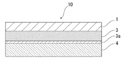
- the battery packaging material of the present invention comprises, for example, as shown in FIG. 1, a laminate having at least a base material layer 1, a barrier layer 3 and a heat fusible resin layer 4 in this order. It is done.
- the base material layer 1 is the outermost layer side
- the heat-fusible resin layer 4 is the innermost layer. That is, when assembling the battery, the battery element is sealed by sealing the battery element by thermally fusing the heat-fusible resin layers 4 located on the peripheral edge of the battery element.
- An acid resistant coating is provided on the surface of at least one side of the barrier layer 3.
- the acid resistant coating contains cerium.
- FIG. 1 the schematic diagram in the case where the battery packaging material of this invention equips the surface by the side of the heat fusible resin layer 4 of the barrier layer 3 with the acid-resistant film 3a is shown.
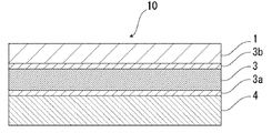
- FIG. 2 the schematic diagram in case the packaging material for batteries of this invention equips both surfaces of the barrier layer 3 with acid-resistant film 3a, 3b, respectively is shown.
- the acid resistant film 3 a may be provided only on the surface of the barrier layer 3 on the side of the heat fusible resin layer 4.
- the acid resistant coating 3 b may be provided only on the surface on the material layer 1 side, or the acid resistant coatings 3 a and 3 b may be provided on both surfaces of the barrier layer 3.
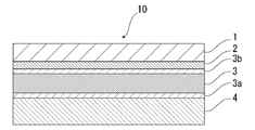
- the battery packaging material of the present invention is provided with an adhesive layer 2 between the base layer 1 and the barrier layer 3 as necessary for the purpose of enhancing the adhesiveness thereof.
- an adhesive layer 5 may be provided between the barrier layer 3 and the heat-fusible resin layer 4 as necessary for the purpose of enhancing the adhesiveness.
- the packaging material for a battery of the present invention is a barrier of the base material layer 1 as needed for the purpose of improving designability, electrolytic solution resistance, abrasion resistance, moldability, etc.
- a surface covering layer 6 may be provided on the side opposite to the layer 3 if necessary.
- the thickness of the laminate constituting the battery packaging material 10 of the present invention is not particularly limited. However, while the thickness of the battery packaging material is reduced to increase the energy density of the battery, the battery is excellent in formability. From the viewpoint of use as a packaging material, for example, about 180 ⁇ m or less, preferably about 150 ⁇ m or less, more preferably about 60 to 180 ⁇ m, further preferably about 60 to 150 ⁇ m.
- MD and TD in the manufacturing process can usually be discriminated for the barrier layer 3 described later.
- the barrier layer 3 is made of aluminum foil
- RD Rolling Direction
- linear streaks called so-called rolling marks are formed on the surface of the aluminum foil. Since the rolling marks extend along the rolling direction, the rolling direction of the aluminum foil can be grasped by observing the surface of the aluminum foil.
- the MD of the laminate and the RD of the aluminum foil coincide, so the surface of the aluminum foil of the laminate is observed to specify the rolling direction (RD) of the aluminum foil.
- the MD of the laminate can be identified.
- the TD of the laminate is perpendicular to the MD of the laminate, the TD of the laminate can also be specified.
- the base material layer 1 is a layer located on the outermost layer side. About the raw material which forms the base material layer 1, it does not restrict
- materials for forming the base material layer 1 include resins such as polyester resin, polyamide resin, epoxy resin, acrylic resin, fluorine resin, polyurethane resin, silicone resin, phenol resin, polycarbonate resin, and mixtures and copolymers thereof A film is mentioned. Among these, a polyester resin and a polyamide resin are preferably mentioned, and a biaxially stretched polyester resin and a biaxially stretched polyamide resin are more preferably mentioned.
- polyester resin examples include polyethylene terephthalate, polybutylene terephthalate, polyethylene naphthalate, polybutylene naphthalate, and copolyester.
- polyamide resin examples include nylon 6, nylon 66, a copolymer of nylon 6 and nylon 66, nylon 6, 10, polyamide MXD 6 (polymetaxylylene adipamide) and the like.
- the base material layer 1 may be formed of a resin film of one layer, but may be formed of a resin film of two or more layers in order to improve pinhole resistance and insulation. Specifically, a multilayer structure in which a polyester film and a nylon film are laminated, a multilayer structure in which a plurality of nylon films are laminated, a multilayer structure in which a plurality of polyester films are laminated, and the like can be mentioned.
- a laminate of a biaxially stretched nylon film and a biaxially stretched polyester film, a laminate of a plurality of biaxially stretched nylon films laminated, and a laminate of a plurality of biaxially stretched polyester films laminated Body is preferred.
- the base material layer 1 is formed of a resin film of two layers, a polyester resin and a polyester resin are laminated, a polyamide resin and a polyamide resin are laminated, or a polyester resin and a polyamide resin are laminated. It is more preferable to use a structure in which polyethylene terephthalate and polyethylene terephthalate are laminated, a structure in which nylon and nylon are laminated, or a structure in which polyethylene terephthalate and nylon are laminated. In addition, since the polyester resin is difficult to be discolored when, for example, the electrolyte solution adheres to the surface, it is preferable to laminate the base material layer 1 so that the polyester resin is positioned at the outermost layer in the laminated structure. When the base material layer 1 has a multilayer structure, the thickness of each layer is preferably about 2 to 25 ⁇ m.
- the base material layer 1 is formed of a multi-layered resin film
- two or more resin films may be laminated via an adhesive or an adhesive component such as an adhesive resin, and the type and amount of the adhesive component used, etc. Is similar to that of the adhesive layer 2 described later.
- limit especially as a method to laminate the resin film of two or more layers A well-known method can be adopted, for example, a dry laminating method, a sandwich laminating method, etc. are mentioned, Preferably a dry laminating method is mentioned.
- a urethane type adhesive is, for example, about 2 to 5 ⁇ m.
- a lubricant is preferably attached to the surface of the base layer 1.
- the lubricant is not particularly limited, but preferably includes amide lubricants.
- Specific examples of the amide-based lubricant include the same as those exemplified for the heat-fusible resin layer 4 described later.
- the amount thereof is not particularly limited, but it is preferably about 3 mg / m 2 or more, more preferably 4 to 5 in an environment of 24 ° C. and 60% relative humidity. It may be about 15 mg / m 2 , more preferably about 5 to 14 mg / m 2 .
- the base material layer 1 may contain a lubricant.
- the lubricant present on the surface of the substrate layer 1 may be one in which the lubricant contained in the resin constituting the substrate layer 1 is exuded, or the lubricant coated on the surface of the substrate layer 1 It may be
- the thickness of the base material layer 1 is not particularly limited as long as it exhibits the function as a base material layer, and for example, about 3 to 50 ⁇ m, preferably about 10 to 35 ⁇ m.
- the adhesive layer 2 is a layer provided between the substrate layer 1 and the barrier layer 3 as needed in order to firmly bond the substrate layer 1 and the barrier layer 3.
- the adhesive layer 2 is formed of an adhesive capable of adhering the base layer 1 and the barrier layer 3.
- the adhesive used to form the adhesive layer 2 may be a two-part curable adhesive, or may be a one-part curable adhesive.
- the adhesive used to form the adhesive layer 2 is not particularly limited, and may be any of a chemical reaction type, a solvent volatilization type, a heat melting type, a heat pressure type, and the like.
- polyester resins such as polyethylene terephthalate, polybutylene terephthalate, polyethylene naphthalate, polybutylene naphthalate, polyethylene isophthalate, copolyester, etc .
- Polyurethane resin Epoxy resin
- Phenolic resin resin Polycarbonate resin
- Polyamide resin such as nylon 6, nylon 66, nylon 12, copolymerized polyamide
- Polyolefin resin polyvinyl acetate resin; cellulose adhesive; (meth) acrylic resin; polyimide resin; amino resin such as urea resin, melamine resin; chloroprene rubber, nitrous resin - rubber, styrene rubbers such as butadiene rubber; and silicone resins.
- These adhesive components may be used alone or in combination of two or more.
- resin used as these adhesion components can improve adhesive strength together with a suitable hardening
- the curing agent is appropriately selected from polyisocyanate, polyfunctional epoxy resin, oxazoline group-containing polymer, polyamine resin, acid anhydride and the like according to the functional group of the adhesive component.
- polyurethane-based adhesives preferably composed of various polyols and polyisocyanates can be mentioned. More preferable examples include two-component polyurethane adhesives of which curing agents are aromatic or aliphatic polyisocyanates with polyols such as polyester polyols, polyether polyols, and acrylic polyols as main agents.
- the thickness of the adhesive layer 2 is not particularly limited as long as it exhibits the function as an adhesive layer, and for example, about 1 to 10 ⁇ m, preferably about 2 to 5 ⁇ m.
- the barrier layer 3 is a layer having a function to prevent water vapor, oxygen, light and the like from invading the inside of the battery, in addition to the strength improvement of the battery packaging material.
- the barrier layer 3 is preferably a metal layer, that is, a layer formed of a metal. Specifically as a metal which comprises the barrier layer 3, aluminum, stainless steel, titanium etc. are mentioned, Preferably aluminum is mentioned.
- the barrier layer 3 can be formed of, for example, a metal foil, a metal vapor deposited film, a film provided with these vapor deposited films, or the like, preferably formed of a metal foil, and more preferably formed of an aluminum alloy foil.
- the barrier layer is made of, for example, annealed aluminum (JIS H4160: 1994 A8021 H-O, JIS H4160: It is more preferable to use a soft aluminum alloy foil such as 1994 A8079 H-O, JIS H4000: 2014 A8021 P-O, JIS H 4000: 2014 A8079 P-O).
- the thickness of the barrier layer 3 is not particularly limited as long as it exhibits a function as a barrier layer such as water vapor, but from the viewpoint of reducing the thickness of the battery packaging material, it is preferably about 100 ⁇ m or less, more preferably 10 to It may be about 100 ⁇ m, more preferably about 10 to 80 ⁇ m.
- an acid resistant coating is provided on the surface of at least one side of the barrier layer 3.
- the acid-resistant film 3a may be provided only on the surface of the barrier layer 3 on the heat fusible resin layer 4 side, or the surface of the barrier layer 3 on the base layer 1 side.
- the acid resistant coating 3b may be provided only on the both sides, and the acid resistant coatings 3a and 3b may be provided on both sides of the barrier layer 3, respectively.
- the peak intensity P CePO4 derived from CePO 4 - is obtained .
- PO 3 - the ratio P PO3 / CePO4 the peak intensity P PO3 derived is characterized in that in the range of 80 to 120.
- the layer adjacent to the side provided with the acid-resistant film of the barrier layer 3 is also a layer even when the electrolytic solution adheres to the battery packaging material. It is excellent in adhesion with a short time.
- the barrier layer provided with the acid resistant coating can maintain high adhesion in a relatively short period of time (for example, about 2 to 5 years), and is used, for example, in mobile devices. Are particularly useful as packaging materials for small batteries.
- the peak intensity P CePO4 derived from CePO 4 - is obtained .
- PO 2 - the ratio P PO2 / CePO4 the peak intensity P PO2 derived is is characterized in that in the range of 90-150.
- the layer adjacent to the side provided with the acid resistant film of the barrier layer 3 is also a layer even when the electrolytic solution adheres to the battery packaging material It is excellent in adhesion with a short time.
- the barrier layer provided with the acid resistant coating can maintain high adhesion in a relatively short period of time, so it is small for use in, for example, mobile devices. It is particularly useful as a battery packaging material for
- the peak intensity ratio P PO3 of the acid resistant coating on any one surface is / CePO 4 or P PO 2 / CePO 4 may be within the above range (that is, in the case of the battery packaging material of the first aspect, the peak intensity ratio P PO 3 / CePO 4 is within the above range)
- the peak intensity ratio P PO2 / CePO4 may fall within the above range), but the peak intensity ratio P is the same for any of the acid resistant coatings 3a and 3b. It is preferable that PO 3 / CePO 4 or P PO 2 / CePO 4 be within the above range, respectively.
- an acid-resistant film located on the heat-fusion resin layer side of the barrier layer, and a layer adjacent thereto (for example, the adhesive layer 5 provided as needed, the heat-fusion resin layer 4 and the like)
- the acid-resistant film 3a is formed on the surface of the barrier layer 3 at least on the heat-fusible resin layer 4 side because the adhesion of the battery is likely to be reduced in a short time preferably be equipped, the peak intensity ratio P PO3 / CePO4 or P PO2 / CePO4 for acid-resistant film 3a, respectively, is preferably within the above range. About these points, it is the same also about each peak intensity ratio shown below.
- CePO 4 - PO 3 to the peak intensity P CePO4 derived from - the ratio P PO3 / CePO4 the peak intensity P PO3 derived is may be in the range of 80 to 120, the acid-resistant coating
- the lower limit of the ratio P PO3 / CePO 4 is preferably about 85 or more, more preferably about 92 or more, and the upper limit is preferably about about 2 or more, from the viewpoint of further improving the adhesion of the provided barrier layer in a short period of time. 110 or less, more preferably about 105 or less, still more preferably about 98 or less.
- the range of the peak intensity ratio P PO 3 / Ce PO 4 is preferably about 80 to 110, about 80 to 105, about 80 to 98, about 85 to 120, about 85 to 110, about 85 to 105, 85 to About 98, about 92 to 120, about 92 to 110, about 92 to 105, about 92 to 98, and the like.
- CePO 4 - PO 2 to the peak intensity P CePO4 derived from - the ratio P PO2 / CePO4 the peak intensity P PO2 derived is may be in the range of 90-150, acid resistance
- the lower limit of the ratio P PO 2 / Ce PO 4 is preferably about 110 or more, and the upper limit is preferably about 130 or less, more preferably from the viewpoint of enhancing the adhesion in a short period of time of the barrier layer provided with the film. Is about 116 or less.
- the range of the peak intensity ratio PPO2 / CePO4 is preferably about 90 to 130, about 90 to 116, about 110 to 150, about 110 to 130, about 110 to 116.
- the POO to the peak intensity P CePO4 derived from CePO 4 - is obtained . 2 - as the ratio P PO2 / CePO4 the peak intensity P PO2 derived from
- the lower limit is preferably about 90 or more can be mentioned
- the upper limit is preferably about 150 or less, or more preferably 130 or less.
- the range of the peak intensity ratio PPO2 / CePO4 in the first aspect is preferably about 90 to about 150, more preferably about 90 to about 130.
- the method of analyzing the acid resistant coatings 3a and 3b using time-of-flight secondary ion mass spectrometry should be performed under the following measurement conditions using a time-of-flight secondary ion mass spectrometer Can.
- the acid-resistant film contains cerium.
- the layers (adhesive layer, heat fusible resin layer, adhesive layer, etc.) laminated on the barrier layer are physically peeled off.
- the barrier layer is placed in an electric furnace, and the organic components present on the surface of the barrier layer are removed at about 300 ° C. for about 30 minutes. Thereafter, X-ray photoelectron spectroscopy of the surface of the barrier layer is used to confirm that cerium is contained.
- the acid resistant coatings 3a and 3b can be formed by chemical conversion treatment of the surface of the barrier layer 3 with a treatment solution containing a cerium compound such as cerium oxide.
- a chemical conversion treatment using a treatment liquid containing a cerium compound for example, one in which a cerium compound such as cerium oxide is dispersed in phosphoric acid and / or a salt thereof is applied to the surface of the barrier layer 3 and baked.
- a cerium compound such as cerium oxide is dispersed in phosphoric acid and / or a salt thereof is applied to the surface of the barrier layer 3 and baked.
- the peak intensity ratio PPO3 / CePO4 or PPO2 / CePO4 of the acid resistant films 3a and 3b is, for example, the composition of the treatment liquid for forming the acid resistant films 3a and 3b, and the production conditions such as the temperature and time of the baking treatment after the treatment. It can be adjusted by
- the ratio of the cerium compound to the phosphoric acid and / or the salt thereof in the treatment liquid containing the cerium compound is not particularly limited, but each of the above peak intensity ratios P PO3 / CePO4 or P PO2 / CePO4 is set within the above range. From the point of view, the ratio of phosphoric acid and / or a salt thereof to 100 parts by mass of the cerium compound is preferably about 12 to about 28, and more preferably about 15 to about 25 parts by mass.
- phosphoric acid and its salt for example, condensed phosphoric acid and its salt can also be used.
- the treatment liquid containing a cerium compound may further contain an anionic polymer and a crosslinking agent for crosslinking the anionic polymer.
- the anionic polymer include poly (meth) acrylic acid or a salt thereof, a copolymer containing (meth) acrylic acid or a salt thereof as a main component, and the like.
- a crosslinking agent the compound which has a functional group of an isocyanate group, a glycidyl group, a carboxyl group, and an oxazoline group, a silane coupling agent, etc. are mentioned.
- the anionic polymer and the crosslinking agent may each be of one type or of two or more types.
- the treatment liquid containing a cerium compound contains an aminated phenol polymer.
- the content of the aminated phenol polymer is preferably about 100 to 400 parts by mass, more preferably about 200 to 300 parts by mass, with respect to 100 parts by mass of the cerium compound.
- the weight-average molecular weight of the aminated phenol polymer is preferably about 5,000 to about 20,000.
- the weight average molecular weight of the aminated phenolic polymer is a value measured by gel permeation chromatography (GPC), which is measured under the condition of using polystyrene as a standard sample.
- the solvent of the treatment liquid containing the cerium compound is not particularly limited as long as it can disperse the components contained in the treatment liquid and evaporate by heating thereafter, but preferably includes water.
- the solid content concentration of the treatment liquid containing a cerium compound is, for example, about 8 to 30% by mass.
- the surface temperature of the barrier layer when applying the treatment liquid to the surface of the barrier layer and heating to form an acid resistant coating is preferably about 190 to 220 ° C., and the heating time is 3 to 6 There is about a second. By adopting such temperature and heating time, the solvent can be appropriately evaporated to form an acid resistant coating layer suitably.
- the solid content concentration of the cerium compound contained in the treatment liquid for forming the acid resistant coating is not particularly limited, but the peak intensity ratio PPO3 / CePO4 or PPO2 / CePO4 is set to the above-mentioned predetermined range, respectively.
- a solvent such as water
- the thickness of the acid resistant coating is not particularly limited, but preferably from about 1 nm to 10 ⁇ m, from the viewpoint of enhancing the adhesion of the barrier layer provided with the acid resistant coating in a short period of time while exhibiting excellent acid resistance. More preferably, it is about 1 to 100 nm, and more preferably about 1 to 50 nm.
- the thickness of the acid resistant coating can be measured by transmission electron microscopy or a combination of observation with a transmission electron microscope and energy dispersive X-ray spectroscopy or electron beam energy loss spectroscopy.
- the bar-coat method As a method of apply
- the peak strength ratio P PO3 / CePO4 or P PO2 / CePO4 is set to the above-described predetermined range to enhance the adhesion in a short period of time of the barrier layer provided with the acid resistant film while exhibiting excellent acid resistance.
- the heating temperature for baking the treatment solution to form an acid resistant coating is preferably about 170 to 250 ° C., more preferably about 180 to 220 ° C.
- the baking time is preferably about 2 to 10 seconds, more preferably about 3 to 6 seconds.
- an alkaline dipping method an electrolytic cleaning method, an acid cleaning method, an electrolytic acid cleaning method, an acid activity It is preferable to carry out the degreasing treatment by a known treatment method such as
- the thermally fusible resin layer 4 corresponds to the innermost layer, and is a layer that thermally fuses the thermally fusible resin layers when the battery is assembled to seal the battery element.
- the resin component used for the heat fusible resin layer 4 is not particularly limited as long as heat fusible is possible, and examples thereof include polyolefin, cyclic polyolefin, acid-modified polyolefin, and acid-modified cyclic polyolefin. That is, the resin constituting the heat-fusible resin layer 4 may or may not contain a polyolefin skeleton, and preferably contains a polyolefin skeleton.
- the resin constituting the heat-fusible resin layer 4 can be analyzed by, for example, infrared spectroscopy, gas chromatography-mass spectrometry, etc., as long as it contains a polyolefin skeleton, and the analysis method is not particularly limited.
- a peak derived from maleic acid is detected in the vicinity of the wave number of 1760 cm -1 and near the wave number 1780 cm -1.
- the peak may be small and not detected. In that case, analysis is possible by nuclear magnetic resonance spectroscopy.
- polystyrene resin examples include polyethylenes such as low density polyethylene, medium density polyethylene, high density polyethylene and linear low density polyethylene; homopolypropylene, block copolymers of polypropylene (for example, block copolymers of propylene and ethylene), polypropylene Polypropylenes such as random copolymers of (for example, random copolymers of propylene and ethylene); terpolymers of ethylene-butene-propylene and the like.
- polyethylenes such as low density polyethylene, medium density polyethylene, high density polyethylene and linear low density polyethylene
- homopolypropylene block copolymers of polypropylene (for example, block copolymers of propylene and ethylene)
- polypropylene Polypropylenes such as random copolymers of (for example, random copolymers of propylene and ethylene); terpolymers of ethylene-butene-propylene and the like.
- polyethylene and polypropylene are mentioned.
- the cyclic polyolefin is a copolymer of an olefin and a cyclic monomer, and examples of the olefin which is a constituent monomer of the cyclic polyolefin include ethylene, propylene, 4-methyl-1-pentene, butadiene, isoprene and the like. .
- a cyclic monomer which is a constituent monomer of the cyclic polyolefin for example, cyclic alkenes such as norbornene; specifically, cyclic dienes such as cyclopentadiene, dicyclopentadiene, cyclohexadiene, norbornadiene, and the like can be mentioned.
- these polyolefins preferred are cyclic alkenes, more preferably norbornene.
- the acid-modified polyolefin is a polymer modified by block copolymerization or graft copolymerization of the polyolefin with an acid component such as a carboxylic acid.
- an acid component such as a carboxylic acid.
- carboxylic acids such as maleic acid, acrylic acid, itaconic acid, crotonic acid, maleic anhydride, itaconic anhydride, or anhydrides thereof.
- the acid-modified cyclic polyolefin is prepared by copolymerizing part of the monomers constituting the cyclic polyolefin with an ⁇ , ⁇ -unsaturated carboxylic acid or an anhydride thereof, or ⁇ , ⁇ - to the cyclic polyolefin. It is a polymer obtained by block copolymerization or graft copolymerization of unsaturated carboxylic acid or its anhydride.
- the cyclic polyolefin to be carboxylic acid modified is the same as described above. Moreover, as a carboxylic acid used for modification
- polyolefins such as polypropylene, carboxylic acid-modified polyolefins, and more preferably polypropylene and acid-modified polypropylenes.
- the heat fusible resin layer 4 may be formed of one type of resin component alone, or may be formed of a blend polymer in which two or more types of resin components are combined. Furthermore, the heat-fusible resin layer 4 may be formed of only one layer, but may be formed of two or more layers of the same or different resin components.
- a lubricant adheres to the surface of the heat-fusible resin layer.
- the lubricant is not particularly limited, but preferably includes amide lubricants.
- Specific examples of the amide lubricant include saturated fatty acid amide, unsaturated fatty acid amide, substituted amide, methylolamide, saturated fatty acid bisamide, unsaturated fatty acid bisamide and the like.
- Specific examples of the saturated fatty acid amide include lauric acid amide, palmitic acid amide, stearic acid amide, behenic acid amide, hydroxystearic acid amide and the like.
- the unsaturated fatty acid amide include oleic acid amide and erucic acid amide.
- substituted amide include N-oleyl palmitic acid amide, N-stearyl stearic acid amide, N-stearyl oleic acid amide, N-oleyl stearic acid amide, N-stearyl erucic acid amide and the like.
- methylolamide include methylol stearic acid amide and the like.
- saturated fatty acid bisamide examples include methylenebisstearic acid amide, ethylenebiscapric acid amide, ethylenebislauric acid amide, ethylenebisstearic acid amide, ethylenebishydroxystearic acid amide, ethylenebisbehenic acid amide, hexamethylene bisstearin Acid amide, hexamethylene bisbehenamide, hexamethylene hydroxystearic amide, N, N'-distearyl adipamide, N, N'-distearyl sebacate amide and the like can be mentioned.
- unsaturated fatty acid bisamides include ethylene bis oleic acid amide, ethylene bis erucic acid amide, hexamethylene bis oleic acid amide, N, N'-dioleyl adipic acid amide, N, N'-dioleyl sebacic acid amide Etc.
- fatty acid ester amides include stearoamidoethyl stearate and the like.
- specific examples of the aromatic bisamides include m-xylylene bis-stearic acid amide, m-xylylene bis-hydroxystearic acid amide, N, N'-distearyl isophthalic acid amide and the like.
- the lubricant may be used alone or in combination of two or more.
- the amount thereof is not particularly limited, but it is preferably about 3 mg / m 2 or more, more preferably in an environment of 24 ° C. and 60% relative humidity. Is about 4 to 15 mg / m 2 , and more preferably about 5 to 14 mg / m 2 .
- the heat fusible resin layer 4 may contain a lubricant.
- the lubricant present on the surface of the heat-fusible resin layer 4 may be one in which the lubricant contained in the resin constituting the heat-fusible resin layer 4 is exuded, or the heat-fusible resin layer The surface of 4 may be coated with a lubricant.
- the thickness of the heat-fusible resin layer 4 is not particularly limited as long as it exhibits the function as a heat-fusible resin layer, but is preferably about 60 ⁇ m or less, more preferably about 15 to 60 ⁇ m, further preferably The thickness may be about 15 to 40 ⁇ m.
- Adhesive layer 5 In the battery packaging material of the present invention, the adhesive layer 5 is a layer optionally provided between the barrier layer 3 and the heat-fusible resin layer 4 in order to enhance the adhesion thereof. Adhesion layer 5 may be constituted by a single layer, and may be constituted by the same or different layers.
- the acid resistant coating has the above-mentioned specific peak intensity ratio, it is excellent in adhesion, and the acid resistant coating 3 a and the adhesive layer 5 The adhesion between them is also effectively enhanced.
- the acid-resistant film is provided in a mode in which the acid-resistant film 3 a on the surface of the barrier layer 3 and the heat-fusible resin layer 4 are laminated via the adhesive layer 5.
- the effect that the adhesion of the barrier layer is excellent can be exhibited particularly effectively.
- the adhesive layer 5 is formed of a resin capable of adhering the barrier layer 3 (further, the acid resistant coating 3 a) and the heat-fusible resin layer 4.
- resin used for formation of adhesion layer 5 the thing of the adhesion mechanism, the kind of adhesive agent component, etc. can use the thing similar to the adhesive illustrated by adhesive agent layer 2.
- polyolefin resin such as polyolefin mentioned above-mentioned heat-fusion resin layer 4
- cyclic polyolefin, carboxylic acid modified polyolefin, carboxylic acid modified cyclic polyolefin can also be used. .
- the polyolefin a carboxylic acid-modified polyolefin is preferable, and a carboxylic acid-modified polypropylene is particularly preferable, from the viewpoint of excellent adhesion between the barrier layer 3 and the heat-fusible resin layer 4. That is, the resin constituting the adhesive layer 5 may or may not contain a polyolefin skeleton, and preferably contains a polyolefin skeleton. It is possible to analyze that the resin constituting the adhesive layer 5 contains a polyolefin skeleton, for example, by infrared spectroscopy, gas chromatography mass spectrometry, etc., and there is no particular limitation on the analysis method.
- a peak derived from maleic acid is detected in the vicinity of the wave number of 1760 cm -1 and near the wave number 1780 cm -1.
- the peak may be small and not detected. In that case, analysis is possible by nuclear magnetic resonance spectroscopy.
- the adhesive layer 5 is a resin composition containing an acid-modified polyolefin and a curing agent. It may be a cured product.
- the acid-modified polyolefin preferably, the same ones as the carboxylic acid-modified polyolefin and the carboxylic acid-modified cyclic polyolefin exemplified in the heat fusible resin layer 4 can be exemplified.
- the curing agent is not particularly limited as long as it cures acid-modified polyolefin.
- examples of the curing agent include epoxy-based curing agents, polyfunctional isocyanate-based curing agents, carbodiimide-based curing agents, oxazoline-based curing agents, and the like.
- the epoxy curing agent is not particularly limited as long as it is a compound having at least one epoxy group.
- the epoxy curing agent include epoxy resins such as bisphenol A diglycidyl ether, modified bisphenol A diglycidyl ether, novolak glycidyl ether, glycerin polyglycidyl ether, polyglycerin polyglycidyl ether and the like.
- the polyfunctional isocyanate-based curing agent is not particularly limited as long as it is a compound having two or more isocyanate groups.
- Specific examples of the polyfunctional isocyanate-based curing agent include isophorone diisocyanate (IPDI), hexamethylene diisocyanate (HDI), tolylene diisocyanate (TDI), diphenylmethane diisocyanate (MDI), those obtained by polymerizing or denating these, or the like Mixtures and copolymers with other polymers may be mentioned.
- curing agent the polycarbodiimide compound which has a carbodiimide group 2 or more at least is preferable.
- the oxazoline-based curing agent is not particularly limited as long as it is a compound having an oxazoline skeleton (oxazoline group).
- Specific examples of the compound having an oxazoline group include those having a polystyrene main chain, and those having an acryl main chain.
- Specific examples of the oxazoline curing agent include Epocross series manufactured by Nippon Shokubai Co., Ltd.
- the curing agent may be composed of two or more types of compounds.
- the content of the curing agent in the resin composition forming the adhesive layer 5 is preferably in the range of about 0.1 to 50% by mass, and more preferably in the range of about 0.1 to 30% by mass, More preferably, it is in the range of about 0.1 to 10% by mass.
- the adhesive layer 5 is a cured product of a resin composition containing an acid-modified polyolefin, and at least one selected from the group consisting of a compound having an isocyanate group, a compound having an oxazoline group, and a compound having an epoxy group. Particularly preferred is a cured product of a resin composition containing an acid-modified polyolefin and at least one selected from the group consisting of a compound having an isocyanate group and a compound having an epoxy group.
- the adhesive layer 5 preferably contains at least one selected from the group consisting of a urethane resin, an ester resin, and an epoxy resin, and more preferably contains a urethane resin and an epoxy resin.
- ester resin an amide ester resin is preferable, for example.
- Amide ester resins are generally formed by the reaction of carboxyl groups with oxazoline groups.
- the adhesive layer 5 is more preferably a cured product of a resin composition containing at least one of these resins and the acid-modified polyolefin.
- the presence of the non-reacted substance is, for example, infrared spectroscopy, It can be confirmed by a method selected from Raman spectroscopy, time-of-flight secondary ion mass spectrometry (TOF-SIMS) and the like.
- a curing agent which has a heterocyclic ring the curing agent which has an oxazoline group, the curing agent which has an epoxy group, etc. are mentioned, for example.
- a curing agent having a C—O—C bond a curing agent having an oxazoline group, a curing agent having an epoxy group, a urethane resin and the like can be mentioned.
- That the adhesive layer 5 is a cured product of a resin composition containing these curing agents is, for example, gas chromatography mass spectrometry (GCMS), infrared spectroscopy (IR), time-of-flight secondary ion mass spectrometry (TOF) -SIMS), X-ray photoelectron spectroscopy (XPS), etc. can confirm.
- GCMS gas chromatography mass spectrometry
- IR infrared spectroscopy
- TOF time-of-flight secondary ion mass spectrometry
- XPS X-ray photoelectron spectroscopy
- the compound having an isocyanate group is not particularly limited, but from the viewpoint of effectively enhancing the adhesion between the acid resistant coating 3 a and the adhesive layer 5, a polyfunctional isocyanate compound is preferably mentioned.
- the polyfunctional isocyanate compound is not particularly limited as long as it is a compound having two or more isocyanate groups. The above-mentioned thing is mentioned as a specific example of a polyfunctional isocyanate type curing agent.
- the content of the compound having an isocyanate group in the adhesive layer 5 is preferably in the range of 0.1 to 50% by mass, and more preferably 0.5 to 40% by mass, in the resin composition constituting the adhesive layer 5. It is more preferable to be in the range. Thereby, the adhesion between the acid resistant film 3 a and the adhesive layer 5 can be effectively enhanced.
- the compound having an oxazoline group is not particularly limited as long as it is a compound having an oxazoline skeleton.
- Specific examples of the compound having an oxazoline group include those having a polystyrene main chain, and those having an acryl main chain. Moreover, the above-mentioned thing etc. are mentioned as a commercial item.
- the proportion of the compound having an oxazoline group in the adhesive layer 5 is preferably in the range of 0.1 to 50% by mass, and more preferably in the range of 0.5 to 40% by mass, in the resin composition constituting the adhesive layer 5. It is more preferable that Thereby, the adhesion between the acid resistant film 3 a and the adhesive layer 5 can be effectively enhanced.
- the epoxy resin is not particularly limited as long as it is a resin capable of forming a cross-linked structure by an epoxy group present in the molecule, and a known epoxy resin can be used.
- the weight average molecular weight of the epoxy resin is preferably about 50 to about 2000, more preferably about 100 to about 1000, and still more preferably about 200 to about 800.
- the weight average molecular weight of the epoxy resin is a value measured by gel permeation chromatography (GPC), which is measured under the condition of using polystyrene as a standard sample.
- the epoxy resin examples include glycidyl ether derivative of trimethylolpropane, bisphenol A diglycidyl ether, modified bisphenol A diglycidyl ether, novolac glycidyl ether, glycerin polyglycidyl ether, polyglycerin polyglycidyl ether and the like.
- the epoxy resin may be used alone or in combination of two or more.
- the proportion of the epoxy resin in the adhesive layer 5 is preferably in the range of 0.1 to 50% by mass, and more preferably in the range of 0.5 to 40% by mass, in the resin composition constituting the adhesive layer 5. Is more preferred. Thereby, the adhesion between the acid resistant film 3 a and the adhesive layer 5 can be effectively enhanced.
- an acid-modified polyolefin functions as a main agent, and a compound having an isocyanate group, a compound having an oxazoline group, and an epoxy resin each function as a curing agent.
- the thickness of the adhesive layer 5 is not particularly limited as long as it exhibits the function as an adhesive layer, but when using the adhesive exemplified in the adhesive layer 2, it is preferably about 1 to 10 ⁇ m, more preferably The order of 1 to 5 ⁇ m can be mentioned. Further, in the case of using the resin exemplified for the heat fusible resin layer 4, it is preferably about 2 to 50 ⁇ m, more preferably about 10 to 40 ⁇ m. In the case of a cured product of an acid-modified polyolefin and a curing agent, it is preferably about 30 ⁇ m or less, more preferably about 0.1 to 20 ⁇ m, and still more preferably about 0.5 to 5 ⁇ m. When the adhesive layer 5 is a cured product of a resin composition containing an acid-modified polyolefin and a curing agent, the adhesive layer 5 can be formed by applying the resin composition and curing it by heating or the like.
- the outer side of the base material layer 1 (the barrier layer of the base material layer 1 as needed) for the purpose of improving designability, electrolytic solution resistance, abrasion resistance, moldability, etc.
- a surface covering layer 6 may be provided on the side opposite to 3). When the surface covering layer 6 is provided, the surface covering layer 6 is the outermost layer of the battery packaging material.
- the surface coating layer 6 can be formed of, for example, polyvinylidene chloride, polyester resin, urethane resin, acrylic resin, epoxy resin or the like. Among these, the surface coating layer 6 is preferably formed of a two-component curable resin. Examples of the two-component curable resin that forms the surface covering layer 6 include a two-component curable urethane resin, a two-component curable polyester resin, and a two-component curable epoxy resin. Further, an additive may be blended in the surface coating layer.
- Examples of the additive include fine particles having a particle diameter of about 0.5 nm to 5 ⁇ m.
- the material of the additive is not particularly limited, and examples thereof include metals, metal oxides, inorganic substances, and organic substances.
- the shape of the additive is not particularly limited, and examples thereof include spheres, fibers, plates, indeterminate shapes, and balloons.
- talc silica, graphite, kaolin, montmorrroid, montmorillonite, synthetic mica, hydrotalcite, silica gel, zeolite, aluminum hydroxide, magnesium hydroxide, zinc oxide, magnesium oxide, aluminum oxide, Neodymium oxide, antimony oxide, titanium oxide, cerium oxide, calcium sulfate, barium sulfate, calcium carbonate, calcium silicate, lithium carbonate, calcium benzoate, calcium oxalate, magnesium stearate, alumina, carbon black, carbon nanotubes, high Melting point nylon, crosslinked acrylic, crosslinked styrene, crosslinked polyethylene, benzoguanamine, gold, aluminum, copper, nickel and the like can be mentioned.
- additives may be used alone or in combination of two or more.
- silica, barium sulfate and titanium oxide are preferably mentioned from the viewpoint of dispersion stability and cost.
- the surface may be subjected to various surface treatments such as insulation treatment, high dispersion treatment, and the like.
- the content of the additive in the surface coating layer 6 is not particularly limited, but preferably about 0.05 to 1.0% by mass, more preferably about 0.1 to 0.5% by mass.
- coating 2-component curable resin which forms a surface coating layer on the surface of the outer side of the base material layer 1 is mentioned.
- the additive may be added to and mixed with the two-component curable resin and then applied.
- the thickness of the surface coating layer 6 is not particularly limited as long as the above-described function as the surface coating layer 6 is exhibited, and for example, about 0.5 to 10 ⁇ m, preferably about 1 to 5 ⁇ m.
- the method for producing the battery packaging material of the present invention is not particularly limited as long as a laminate obtained by laminating each layer of a predetermined composition is obtained, and the battery packaging material of the first aspect
- the step of forming a laminate by laminating at least the base layer, the barrier layer, and the heat-fusible resin layer in this order, and laminating the barrier layer, on at least one side surface of the barrier layer comprises an oxidation-resistant film, the acid-resistant film, when analyzed using time-of-flight secondary ion mass spectrometry, CePO 4 - derived peak intensity P CePO4
- CePO 4 - derived peak intensity P CePO4 There is a method in which the ratio P PO3 / CePO4 of the peak intensity P PO3 derived from PO 3 - to P 3 is in the range of 80 to 120.
- the battery packaging material of the second aspect includes a step of laminating at least a base material layer 1, a barrier layer 3, and a heat-fusible resin layer 4 in this order, and the barrier layer from - when stacking, on at least one side surface of the barrier layer comprises an oxidation-resistant film, the acid-resistant film, when analyzed using time-of-flight secondary ion mass spectrometry, CePO 4 PO 2 to the peak intensity P CePO4 that - the ratio P PO2 / CePO4 the peak intensity P PO2 derived may be mentioned a method using what is in the range of 90-150.
- a laminate in which the base material layer 1, the adhesive layer 2 provided as necessary, and the barrier layer 3 are sequentially laminated is formed.
- the formation of the laminate A is used to form the adhesive layer 2 in the base layer 1 or the barrier layer 3 (when the acid resistant film 3 a is provided, the acid resistant film 3 a, hereinafter omitted)
- the adhesive is applied and dried by a coating method such as a gravure coating method or a roll coating method, and then the dry lamination method is performed in which the barrier layer 3 or the substrate layer 1 is laminated and the adhesive layer 2 is cured. it can.
- the formation method of acid-resistant film 3a, 3b is as above-mentioned.
- the heat fusible resin layer 4 is laminated on the barrier layer 3 of the laminate A.
- the resin component constituting the heat fusible resin layer 4 is gravure-coated or roll-coated on the barrier layer 3 of the laminate A It may be applied by a method such as When the adhesive layer 5 is provided between the barrier layer 3 and the heat fusible resin layer 4, for example, (1) the adhesive layer 5 and the heat fusible resin layer on the barrier layer 3 of the laminate A Method of laminating 4 by coextrusion (co-extrusion laminating method), (2) Separately, a laminated body in which the adhesive layer 5 and the heat-fusible resin layer 4 are laminated is formed, (3) A method of laminating by thermal laminating method, (3) A method of extruding or solution coating an adhesive for forming the adhesive layer 5 on the barrier layer 3 of the laminated body A, drying at a high temperature, and baking Method of laminating the thermally fusible resin layer
- the surface covering layer 6 When the surface covering layer 6 is provided, the surface covering layer is laminated on the surface of the base layer 1 opposite to the barrier layer 3.
- the surface coating layer can be formed, for example, by applying the above-mentioned resin forming the surface coating layer to the surface of the base material layer 1.
- the order of the step of laminating the barrier layer 3 on the surface of the base layer 1 and the step of laminating the surface coating layer on the surface of the base layer 1 is not particularly limited.
- the barrier layer 3 may be formed on the surface of the base material layer 1 opposite to the surface coating layer.
- the surface covering layer 6 / base layer 1 / optional layer 1 / optional adhesive layer 2 / at least one surface is provided with an acid resistant film / optional layer
- a laminate of the adhesive layer 5 / thermal adhesive resin layer 4 to be provided is formed, but in order to strengthen the adhesiveness of the adhesive layer 2 and the adhesive layer 5 to be provided if necessary, It may be subjected to heat treatment such as hot roll contact, hot air, near infrared, far infrared or the like.
- each layer constituting the laminate improves or stabilizes film forming ability, lamination processing, final product secondary processing (pouching, embossing) suitability, etc., as necessary.
- surface activation treatments such as corona treatment, blast treatment, oxidation treatment, and ozone treatment may be performed.
- the battery packaging material of the present invention is used for a package for sealing and housing battery elements such as a positive electrode, a negative electrode, and an electrolyte. That is, the battery element provided with at least a positive electrode, a negative electrode, and an electrolyte can be accommodated in a package formed of the battery packaging material of the present invention to make a battery.
- the aforementioned peak strength and the like can be analyzed by cutting out the battery packaging material from the battery.
- a sample is obtained from a portion, such as the top and bottom surfaces of the battery, from which the heat fusible resin layers are not heat-fused and subjected to analysis.
- a battery element comprising at least a positive electrode, a negative electrode, and an electrolyte is a battery packaging material of the present invention, in which the metal terminal connected to each of the positive electrode and the negative electrode protrudes outward.
- the battery is covered by forming flanges (areas in which the heat fusible resin layers are in contact with each other) on the periphery of the element, and heat sealing the heat fusible resin layers of the flanges to seal them.
- a battery using a packaging material is provided.
- the battery packaging material of the present invention may be used for either a primary battery or a secondary battery, but is preferably a secondary battery.
- the type of secondary battery to which the battery packaging material of the present invention is applied is not particularly limited.
- lithium ion battery, lithium ion polymer battery, lead storage battery, nickel hydrogen storage battery, nickel cadmium storage battery, nickel Iron storage batteries, nickel-zinc storage batteries, silver oxide-zinc storage batteries, metal air batteries, multivalent cation batteries, capacitors, capacitors and the like can be mentioned.
- lithium ion batteries and lithium ion polymer batteries are mentioned as a suitable application object of the packaging material for batteries of the present invention.
- the barrier layer provided with the acid resistant coating can maintain high adhesion in a relatively short period of time. Therefore, the battery packaging material of the present invention is particularly useful, for example, as a packaging material for small batteries used in mobile devices and the like.
- Example 1 As a base material layer, polyethylene terephthalate and nylon were laminated by coextrusion, and a biaxially stretched laminated film was prepared.
- a resin containing a modified thermoplastic resin graft-modified with an unsaturated carboxylic acid derivative component between a biaxially stretched polyethylene terephthalate film (thickness 5 ⁇ m) and a biaxially stretched nylon film (thickness 20 ⁇ m) It is adhered by an adhesive layer (adhesive, 1 ⁇ m thick) using the composition.
- two layers of the barrier layer comprising an aluminum foil (JIS H4160: 1994 A8021 H-O, thickness 40 ⁇ m) provided with an acid resistant coating (thickness 20 nm) are subjected to chemical conversion treatment on both sides by a method described later.
- the film was laminated on the surface of the axially stretched nylon film by dry lamination. Specifically, a two-component urethane adhesive (polyol compound and aromatic isocyanate compound) was applied to one surface of an aluminum foil provided with an acid resistant film to form an adhesive layer (3 ⁇ m in thickness).
- an adhesive (3 ⁇ m in thickness after curing) consisting of a non-crystalline polyolefin resin having a carboxyl group and a polyfunctional isocyanate compound is applied as an adhesive layer on the surface of the acid resistant film of the obtained laminate. , Dried.
- an unstretched laminated polypropylene film random polypropylene (thickness 5 ⁇ m) / block polypropylene (thickness 30 ⁇ m) / random polypropylene (thickness 5 ⁇ m), total thickness
- the adhesive layer / heat-sealable resin layer was laminated on the barrier layer by laminating 40 ⁇ m) and passing through and bonding between two heated rolls.
- the obtained laminate is cured (aging) to obtain a biaxially stretched polyethylene terephthalate film (5 ⁇ m) / adhesive (1 ⁇ m) / biaxially stretched nylon film (20 ⁇ m) / adhesive layer (3 ⁇ m) / both sides
- a battery packaging material is obtained in which a barrier layer (40 ⁇ m) / adhesive layer (3 ⁇ m) / unstretched laminated polypropylene film (40 ⁇ m) provided with an acid resistant film (thickness 20 nm) is laminated in this order.
- the acid-resistant film on the surface of the barrier layer contains 20 parts by mass of an inorganic phosphorus compound (sodium phosphate) with 100 parts by mass of cerium oxide (water as a solvent is contained, and the solid concentration is Prepare a solution of about 10% by mass), and apply the treatment solution on both sides of the barrier layer (film thickness after drying is 20 nm), and the surface temperature of the barrier layer is about 190 to 230 ° C., 3 to 6 It was formed by heating and drying for about a second.
- an inorganic phosphorus compound sodium phosphate
- cerium oxide water as a solvent is contained
- Example 2 An unstretched laminated polypropylene film (random polypropylene (thickness 10 ⁇ m) / block polypropylene (thickness 60 ⁇ m) / random polypropylene (a thickness of 60 ⁇ m) instead of the unstretched laminated polypropylene film (thickness 40 ⁇ m) as a heat fusible resin layer Biaxially stretched polyethylene terephthalate film (5 ⁇ m) / adhesive (1 ⁇ m) / biaxially stretched nylon film (20 ⁇ m) / in the same manner as in Example 1 except that a thickness of 10 ⁇ m) and a total thickness of 80 ⁇ m) were used.
- Random polypropylene (thickness 10 ⁇ m) / block polypropylene (thickness 60 ⁇ m) / random polypropylene (a thickness of 60 ⁇ m) instead of the unstretched laminated polypropylene film (thickness 40 ⁇ m) as a heat fusible resin layer
- the aluminum foil as a barrier layer used what was equipped with the same acid-resistant film as Example 1.
- an adhesive (3 ⁇ m in thickness after curing) consisting of a non-crystalline polyolefin resin having a carboxyl group and a polyfunctional isocyanate compound is applied as an adhesive layer on the surface of the acid resistant film of the obtained laminate. , Dried.
- unstretched laminated polypropylene film random polypropylene (4 ⁇ m thick) / block polypropylene (22 ⁇ m thick) / random polypropylene (4 ⁇ m thick
- total as the first heat-welding resin layer total 30 .mu.m thick
- the formation of the acid resistant coating on the surface of the barrier layer was performed as follows.
- a treatment liquid containing 43 parts by mass of aminated phenolic polymer, 16 parts by mass of chromium fluoride and 13 parts by mass of phosphoric acid with respect to 100 parts of water is easily applied, and the treatment liquid is applied to both sides of the barrier layer (after drying)
- the film is heated and dried for about 3 to 6 seconds at a temperature at which the surface temperature of the barrier layer is about 190 to 230.degree. C.
- Comparative example 2 A biaxially stretched nylon film (20 ⁇ m) / in the same manner as Comparative Example 1 except that random polypropylene (20 ⁇ m thick) was extruded instead of random polypropylene (50 ⁇ m thick) as the heat fusible resin layer.
- a laminated battery packaging material was obtained.
- the aluminum foil as a barrier layer used what was equipped with the same acid-resistant film as the comparative example 1.
- Example 1 the formation of the acid-resistant film on the surface of the barrier layer is about half (mass ratio) of the phosphoric acid in Example 1 in Comparative Example 3 and about 1.5 in Example 3 in Comparative Example 4.
- a packaging material for a battery was obtained in the same manner as in Example 1, except that the treatment was carried out so as to be about double (mass ratio).
- the analysis of the acid resistant film was performed as follows. First, the space between the barrier layer and the adhesive layer was peeled off. Under the present circumstances, it was made to exfoliate physically, without using the water, the organic solvent, and the aqueous solution of an acid and an alkali. After peeling between the barrier layer and the adhesive layer, since the adhesive layer remained on the surface of the barrier layer, the remaining adhesive layer was removed by etching with Ar-GCIB. With respect to the surface of the barrier layer thus obtained, analysis of the acid resistant film was conducted using time-of-flight secondary ion mass spectrometry.
- Measurement device ION-TOF time-of-flight secondary ion mass spectrometer TOF.
- SIMS 5 Measurement conditions
- Primary ion Double charge ion of bismuth cluster (Bi 3 ++ )
- Primary ion acceleration voltage 30 kV Mass range (m / z): 0 to 1500 Measurement range: 100 ⁇ m ⁇ 100 ⁇ m Number of scans: 16 scan / cycle Number of pixels (one side): 256 pixels
- Etching ion Ar gas cluster ion beam (Ar-GCIB) Etching ion acceleration voltage: 5.0 kV
- each battery packaging material obtained above was cut into a size of 15 mm (TD: Transverse Direction, horizontal direction) and 100 mm (MD: Machine Direction, vertical direction) to obtain test pieces.
- the glass bottle was covered and sealed.
- the sealed glass bottle was placed in an oven set at 85 ° C. and allowed to stand for 24 hours.
- the glass bottle was taken out of the oven, the test piece was further taken out of the glass bottle, washed with water, and the water on the surface of the test piece was wiped off with a towel.
- the heat fusible resin layer of the test piece and the barrier layer are peeled off, and the heat fusible resin layer side and the barrier layer side of the test piece are subjected to a tensile testing machine (trade name AGS-XPlus manufactured by Shimadzu Corporation).
- the peeling distance (N / 15 mm) of the test piece was measured by pulling in the direction of 180 ° at a speed of 50 mm / min with a distance between marked lines of 50 mm, using a marked line distance.
- the measurement of the peeling strength of a test piece was performed within 10 minutes, after wiping off the water
- initial adhesion was evaluated as follows. First, the battery packaging materials obtained in Examples 1 and 2 and Comparative Examples 1 to 4 were cut into test pieces of 15 mm (TD) and 100 mm (MD). Next, the heat fusible resin layer of the test piece and the barrier layer are peeled off, and the heat fusible resin layer and the barrier layer are marked using a tensile tester (trade name AGS-XPlus manufactured by Shimadzu Corporation). Between the distance of 50 mm, it was pulled in the direction of 180 ° at a speed of 50 mm / min, and the peel strength (N / 15 mm) of the test piece was measured to obtain initial adhesion. The results are shown in Table 1. When the heat fusible resin layer and the barrier layer are separated, the adhesive layer located between these layers is in a state of being laminated on either or both of the heat fusible resin layer and the barrier layer. It becomes.
- the surface of the barrier layer comprises an oxidation-resistant film, the acid-resistant film, when analyzed using time-of-flight secondary ion mass spectrometry, CePO 4 - to PO 3 for derived peak intensity P CePO4 - the ratio P PO3 / CePO4 from the peak intensity P PO3 is, the battery packaging material of example 1 and 2 are within the range of 80 to 120, the surface of the barrier layer It can be seen that, despite the provision of the acid-resistant coating, the adhesion between the barrier layer and the heat-fusible resin layer is excellent after immersion in the electrolytic solution.
- the battery packaging material of Example 1 and 2, CePO 4 - PO 2 to the peak intensity P CePO4 derived from - the ratio P PO2 / CePO4 the peak intensity P PO2 derived is in the range of 90-150
- the adhesion between the barrier layer and the heat-sealable resin layer was excellent.
Landscapes
- Chemical & Material Sciences (AREA)
- Chemical Kinetics & Catalysis (AREA)
- Electrochemistry (AREA)
- General Chemical & Material Sciences (AREA)
- Engineering & Computer Science (AREA)
- Power Engineering (AREA)
- Microelectronics & Electronic Packaging (AREA)
- Sealing Battery Cases Or Jackets (AREA)
- Laminated Bodies (AREA)
Abstract
耐酸性皮膜を備えたバリア層の密着性に優れた電池用包装材料を提供する。 本発明の電池用包装材料は、少なくとも、基材層と、バリア層と、熱融着性樹脂層とをこの順に備える積層体から構成されており、 前記バリア層の少なくとも一方側の表面には、耐酸性皮膜を備えており、 前記耐酸性皮膜について、飛行時間型2次イオン質量分析法を用いて分析した場合に、CePO4 -に由来するピーク強度PCePO4に対するPO3 -に由来するピーク強度PPO3の比PPO3/CePO4が、80~120の範囲内にある。
Description
本発明は、電池用包装材料、電池用包装材料の製造方法、及び電池に関する。
従来、様々なタイプの電池が開発されている。これらの電池において、電極、電解質などにより構成される電池素子は、包装材料などにより封止される必要がある。電池用包装材料としては、金属製の包装材料が多用されている。
近年、電気自動車、ハイブリッド電気自動車、パーソナルコンピュータ、カメラ、携帯電話などの高性能化に伴い、多様な形状を有する電池が求められている。また、電池には、薄型化、軽量化なども求められている。しかしながら、従来多用されている金属製の包装材料では、電池形状の多様化に追従することが困難である。また、金属製であるため、包装材料の軽量化にも限界がある。
そこで、多様な形状に加工が容易で、薄型化や軽量化を実現し得る電池用包装材料として、基材層/バリア層/熱融着性樹脂層が順次積層されたフィルム状の積層体が提案されている(例えば、特許文献1を参照)。
このようなフィルム状の電池用包装材料においては、一般的に、成形により凹部が形成され、当該凹部によって形成された空間に電極や電解液などの電池素子を配し、熱融着性樹脂層同士を熱融着させることにより、電池用包装材料の内部に電池素子が収容された電池が得られる。
電池の内部に水分が侵入すると、水分と電解質などとが反応して、酸性物質を生成することがある。例えば、リチウムイオン電池などに使用されている電解液には、電解質となるフッ素化合物(LiPF6、LiBF4など)が含まれており、フッ素化合物が水と反応すると、フッ化水素を発生することが知られている。
フィルム状の積層体によって形成された電池用包装材料のバリア層は、通常、金属箔などによって構成されており、バリア層に酸が接触すると腐食しやすいという問題がある。このような電池用包装材料の耐酸性を高める技術としては、化成処理によって表面に耐酸性皮膜を形成したバリア層を用いる技術が知られている。
従来、耐酸性皮膜を形成する化成処理としては、酸化クロムなどのクロム化合物を用いたクロメート処理、リン酸化合物を用いたリン酸処理など種々の方法が知られている。
しかしながら、本発明者らが検討を重ねたところ、耐酸性皮膜を備えた従来のバリア層は、耐酸性皮膜を設けた側に隣接する層との密着性(すなわち、耐酸性皮膜と、これに接する層との界面における密着性)が不十分になることが明らかとなった。より具体的には、電池用包装材料に電解液が付着することによって、当該密着性が不十分になる場合がある。
また、電池の中でも、特に、モバイル機器(例えば、携帯電話、ノートパソコン、ゲーム機器、ドローンなど)に使用される電池は、小型であり、比較的使用期間が短いため、短期間での高い密着性の保持が求められている。なお、本明細書において、短期間とは、通常のモバイル機器に求められる電池の寿命程度の期間であり、例えば2~5年程度である。
このような状況下、本発明は、耐酸性皮膜を備えたバリア層の短期間での密着性に優れた電池用包装材料を提供することを主な目的とする。さらに、本発明は、当該電池用包装材料の製造方法、及び当該電池用包装材料を用いた電池を提供することも目的とする。
本発明者らは、上記のような課題を解決すべく鋭意検討を行った。その結果、少なくとも、基材層と、バリア層と、熱融着性樹脂層とをこの順に備える積層体から構成されており、バリア層の少なくとも一方側の表面には、耐酸性皮膜を備えており、耐酸性皮膜について、飛行時間型2次イオン質量分析法を用いて分析した場合に、CePO4
-に由来するピーク強度PCePO4に対するPO3
-に由来するピーク強度PPO3の比PPO3/CePO4が、80~120の範囲内にある電池用包装材料は、電解液が付着した際の短期間での密着性に優れることを見出した。
さらに、本発明者らは、少なくとも、基材層と、バリア層と、熱融着性樹脂層とをこの順に備える積層体から構成されており、バリア層の少なくとも一方側の表面には、耐酸性皮膜を備えており、耐酸性皮膜について、飛行時間型2次イオン質量分析法を用いて分析した場合に、CePO4
-に由来するピーク強度PCePO4に対するPO2
-に由来するピーク強度PPO2の比PPO2/CePO4が、90~150の範囲内にある電池用包装材料についても、バリア層の表面に耐酸性皮膜を備えているにも拘わらず、電解液が付着した際の短期間での密着性に優れることを見出した。
特に、本発明者らは、これらの耐酸性皮膜を備えるバリア層は、比較的短期間における高い密着性を保持することができ、例えばモバイル機器などに使用される小型の電池の包装材料として、特に有用であることを見出した。
本発明は、これらの知見に基づいて、さらに検討を重ねることにより完成された発明である。
本発明は、これらの知見に基づいて、さらに検討を重ねることにより完成された発明である。
すなわち、本発明は、下記に掲げる態様の発明を提供する。
項1. 少なくとも、基材層と、バリア層と、熱融着性樹脂層とをこの順に備える積層体から構成されており、
前記バリア層の少なくとも一方側の表面には、耐酸性皮膜を備えており、
前記耐酸性皮膜について、飛行時間型2次イオン質量分析法を用いて分析した場合に、CePO4 -に由来するピーク強度PCePO4に対するPO3 -に由来するピーク強度PPO3の比PPO3/CePO4が、80~120の範囲内にある、電池用包装材料。
項2. 前記バリア層の少なくとも前記熱融着性樹脂層側の表面に、前記耐酸性皮膜を備えている、項1に記載の電池用包装材料。
項3. 前記耐酸性皮膜と前記熱融着性樹脂層とが、接着層を介して積層されている、項2に記載の電池用包装材料。
項4. 前記接着層を構成している樹脂は、ポリオレフィン骨格を有している、項3に記載の電池用包装材料。
項5. 前記接着層が、酸変性ポリオレフィンを含む、項3又は4に記載の電池用包装材料。
項6. 前記接着層を赤外分光法で分析すると、無水マレイン酸に由来するピークが検出される、項3~5のいずれかに記載の電池用包装材料。
項7. 前記接着層の前記酸変性ポリオレフィンが、無水マレイン酸変性ポリプロピレンであり、
前記熱融着性樹脂層が、ポリプロピレンを含む、項6に記載の電池用包装材料。
項8. 前記接着層が、イソシアネート基を有する化合物、オキサゾリン基を有する化合物、及びエポキシ基を有する化合物からなる群より選択される少なくとも1種を含む樹脂組成物の硬化物である、項3~7のいずれかに記載の電池用包装材料。
項9. 前記接着層が、酸素原子、複素環、C=N結合、及びC-O-C結合からなる群より選択される少なくとも1種を有する硬化剤を含む樹脂組成物の硬化物である、項3~8のいずれかに記載の電池用包装材料。
項10. 前記接着層が、ウレタン樹脂、エステル樹脂、及びエポキシ樹脂からなる群より選択される少なくとも1種を含む、項3~9のいずれかに記載の電池用包装材料。
項11. 前記バリア層が、アルミニウム箔により構成されている、項1~10のいずれかに記載の電池用包装材料。
項12. 前記熱融着性樹脂層を構成している樹脂が、ポリオレフィン骨格を含んでいる、項1~11のいずれかに記載の電池用包装材料。
項13. モバイル機器の電池に使用される包装材料である、項1~12のいずれかに記載の電池用包装材料。
項14. 少なくとも、基材層と、バリア層と、熱融着性樹脂層とがこの順となるように積層して積層体を得る工程を備えており、
前記バリア層を積層する際に、前記バリア層の少なくとも一方側の表面に、耐酸性皮膜を備えており、耐酸性皮膜について、飛行時間型2次イオン質量分析法を用いて分析した場合に、CePO4 -に由来するピーク強度PCePO4に対するPO3 -に由来するピーク強度PPO3の比PPO3/CePO4が、80~120の範囲内である、電池用包装材料の製造方法。
項15. 少なくとも正極、負極、及び電解質を備えた電池素子が、項1~13のいずれかに記載の電池用包装材料により形成された包装体中に収容されている、電池。
項16. 少なくとも、基材層と、バリア層と、熱融着性樹脂層とをこの順に備える積層体の電池用包装材料への使用であって、
前記バリア層の少なくとも一方側の表面には、耐酸性皮膜を備えており、
前記耐酸性皮膜について、飛行時間型2次イオン質量分析法を用いて分析した場合に、CePO4 -に由来するピーク強度PCePO4に対するPO3 -に由来するピーク強度PPO3の比PPO3/CePO4が、80~120の範囲内にある、前記積層体の電池用包装材料への使用。
本発明によれば、耐酸性皮膜を備えたバリア層の短期間での密着性に優れた電池用包装材料を提供することができる。また、本発明によれば、当該電池用包装材料の製造方法、及び当該電池用包装材料を用いた電池を提供することもできる。
本発明の第1の態様の電池用包装材料は、少なくとも、基材層と、バリア層と、熱融着性樹脂層とをこの順に備える積層体から構成されており、バリア層の少なくとも一方側の表面には、耐酸性皮膜を備えており、耐酸性皮膜について、飛行時間型2次イオン質量分析法を用いて分析した場合に、CePO4
-に由来するピーク強度PCePO4に対するPO3
-に由来するピーク強度PPO3の比PPO3/CePO4が、80~120の範囲内にあることを特徴とする。
また、本発明の第2の態様の電池用包装材料は、少なくとも、基材層と、バリア層と、熱融着性樹脂層とをこの順に備える積層体から構成されており、バリア層の少なくとも一方側の表面には、耐酸性皮膜を備えており、耐酸性皮膜について、飛行時間型2次イオン質量分析法を用いて分析した場合に、CePO4
-に由来するピーク強度PCePO4に対するPO2
-に由来するピーク強度PPO2の比PPO2/CePO4が、90~150の範囲内にあることを特徴とする。
以下、図1から図5を参照しながら、本発明の電池用包装材料、当該電池用包装材料の製造方法、及び当該電池用包装材料を用いた電池について、詳述する。
なお、本明細書において、「~」で示される数値範囲は「以上」、「以下」を意味する。例えば、2~15mmとの表記は、2mm以上15mm以下を意味する。
1.電池用包装材料の積層構造
本発明の電池用包装材料は、例えば図1に示すように、少なくとも、基材層1、バリア層3、熱融着性樹脂層4をこの順に有する積層体から構成されている。本発明の電池用包装材料において、基材層1が最外層側になり、熱融着性樹脂層4は最内層になる。即ち、電池の組み立て時に、電池素子の周縁に位置する熱融着性樹脂層4同士が熱融着して電池素子を密封することにより、電池素子が封止される。
本発明の電池用包装材料は、例えば図1に示すように、少なくとも、基材層1、バリア層3、熱融着性樹脂層4をこの順に有する積層体から構成されている。本発明の電池用包装材料において、基材層1が最外層側になり、熱融着性樹脂層4は最内層になる。即ち、電池の組み立て時に、電池素子の周縁に位置する熱融着性樹脂層4同士が熱融着して電池素子を密封することにより、電池素子が封止される。
バリア層3の少なくとも一方側の表面には、耐酸性皮膜を備えている。当該耐酸性皮膜は、セリウムを含んでいる。図1には、本発明の電池用包装材料が、バリア層3の熱融着性樹脂層4側の表面に、耐酸性皮膜3aを備える場合の模式図を示している。また、図2には、本発明の電池用包装材料が、バリア層3の両面に、それぞれ、耐酸性皮膜3a,3bを備える場合の模式図を示している。なお、後述の通り、本発明の電池用包装材料においては、バリア層3の熱融着性樹脂層4側の表面のみに、耐酸性皮膜3aを備えていてもよいし、バリア層3の基材層1側の表面のみに、耐酸性皮膜3bを備えていてもよいし、バリア層3の両面に、それぞれ、耐酸性皮膜3a,3bを備えていてもよい。
本発明の電池用包装材料は、図3に示すように、基材層1とバリア層3との間に、これらの接着性を高める目的で、必要に応じて、接着剤層2を備えていてもよい。また、図4に示すように、バリア層3と熱融着性樹脂層4との間に、これらの接着性を高める目的で、必要に応じて、接着層5を備えていてもよい。また、本発明の電池用包装材料は、図5に示すように、意匠性、耐電解液性、耐擦過性、成形性の向上などを目的として、必要に応じて、基材層1のバリア層3とは反対側に、必要に応じて、表面被覆層6を備えていてもよい。
本発明の電池用包装材料10を構成する積層体の厚さとしては、特に制限されないが、電池用包装材料の厚さを薄くして電池のエネルギー密度を高めつつ、成形性に優れた電池用包装材料とする観点からは、例えば約180μm以下、好ましくは約150μm以下、より好ましくは60~180μm程度、さらに好ましくは60~150μm程度が挙げられる。
なお、電池用包装材料において、後述のバリア層3については、通常、その製造過程におけるMDとTDを判別することができる。例えば、バリア層3がアルミニウム箔により構成されている場合、アルミニウム箔の圧延方向(RD:Rolling Direction)には、アルミニウム箔の表面に、いわゆる圧延痕と呼ばれる線状の筋が形成されている。圧延痕は、圧延方向に沿って伸びているため、アルミニウム箔の表面を観察することによって、アルミニウム箔の圧延方向を把握することができる。また、積層体の製造過程においては、通常、積層体のMDと、アルミニウム箔のRDとが一致するため、積層体のアルミニウム箔の表面を観察し、アルミニウム箔の圧延方向(RD)を特定することにより、積層体のMDを特定することができる。また、積層体のTDは、積層体のMDとは垂直方向であるため、積層体のTDについても特定することができる。
2.電池用包装材料を形成する各層
[基材層1]
本発明の電池用包装材料において、基材層1は最外層側に位置する層である。基材層1を形成する素材については、絶縁性を備えるものであることを限度として特に制限されるものではない。基材層1を形成する素材としては、例えば、ポリエステル樹脂、ポリアミド樹脂、エポキシ樹脂、アクリル樹脂、フッ素樹脂、ポリウレタン樹脂、珪素樹脂、フェノール樹脂、ポリカーボネート樹脂及びこれらの混合物や共重合物などの樹脂フィルムが挙げられる。これらの中でも、好ましくはポリエステル樹脂、ポリアミド樹脂が挙げられ、より好ましくは2軸延伸ポリエステル樹脂、2軸延伸ポリアミド樹脂が挙げられる。ポリエステル樹脂としては、具体的には、ポリエチレンテレフタレート、ポリブチレンテレフタレート、ポリエチレンナフタレート、ポリブチレンナフタレート、共重合ポリエステルなどが挙げられる。また、ポリアミド樹脂としては、具体的には、ナイロン6、ナイロン66、ナイロン6とナイロン66との共重合体、ナイロン6,10、ポリアミドMXD6(ポリメタキシリレンアジパミド)などが挙げられる。
基材層1は、1層の樹脂フィルムから形成されていてもよいが、耐ピンホール性や絶縁性を向上させるために、2層以上の樹脂フィルムで形成されていてもよい。具体的には、ポリエステルフィルムとナイロンフィルムとを積層させた多層構造、ナイロンフィルムを複数積層させた多層構造、ポリエステルフィルムを複数積層させた多層構造などが挙げられる。基材層1が多層構造である場合、2軸延伸ナイロンフィルムと2軸延伸ポリエステルフィルムの積層体、2軸延伸ナイロンフィルムを複数積層させた積層体、2軸延伸ポリエステルフィルムを複数積層させた積層体が好ましい。例えば、基材層1を2層の樹脂フィルムから形成する場合、ポリエステル樹脂とポリエステル樹脂を積層する構成、ポリアミド樹脂とポリアミド樹脂を積層する構成、又はポリエステル樹脂とポリアミド樹脂を積層する構成にすることが好ましく、ポリエチレンテレフタレートとポリエチレンテレフタレートを積層する構成、ナイロンとナイロンを積層する構成、又はポリエチレンテレフタレートとナイロンを積層する構成にすることがより好ましい。また、ポリエステル樹脂は、例えば電解液が表面に付着した際に変色し難いことなどから、当該積層構成においては、ポリエステル樹脂が最外層に位置するように基材層1を積層することが好ましい。基材層1を多層構造とする場合、各層の厚さとして、好ましくは2~25μm程度が挙げられる。
基材層1を多層の樹脂フィルムで形成する場合、2以上の樹脂フィルムは、接着剤又は接着性樹脂などの接着成分を介して積層させればよく、使用される接着成分の種類や量などについては、後述する接着剤層2の場合と同様である。なお、2層以上の樹脂フィルムを積層させる方法としては、特に制限されず、公知方法が採用でき、例えばドライラミネート法、サンドイッチラミネート法などが挙げられ、好ましくはドライラミネート法が挙げられる。ドライラミネート法により積層させる場合には、接着層としてウレタン系接着剤を用いることが好ましい。このとき、接着層の厚さとしては、例えば2~5μm程度が挙げられる。
本発明において、電池用包装材料の成形性を高める観点からは、基材層1の表面には、滑剤が付着していることが好ましい。滑剤としては、特に制限されないが、好ましくはアミド系滑剤が挙げられる。アミド系滑剤の具体例としては、後述の熱融着性樹脂層4で例示したものと同じものが挙げられる。
基材層1の表面に滑剤が存在する場合、その存在量としては、特に制限されないが、温度24℃、相対湿度60%の環境において、好ましくは約3mg/m2以上、より好ましくは4~15mg/m2程度、さらに好ましくは5~14mg/m2程度が挙げられる。
基材層1の中には、滑剤が含まれていてもよい。また、基材層1の表面に存在する滑剤は、基材層1を構成する樹脂に含まれる滑剤を滲出させたものであってもよいし、基材層1の表面に滑剤を塗布したものであってもよい。
基材層1の厚さについては、基材層としての機能を発揮すれば特に制限されないが、例えば、3~50μm程度、好ましくは10~35μm程度が挙げられる。
[接着剤層2]
本発明の電池用包装材料10において、接着剤層2は、基材層1とバリア層3を強固に接着させるために、必要に応じて、これらの間に設けられる層である。
本発明の電池用包装材料10において、接着剤層2は、基材層1とバリア層3を強固に接着させるために、必要に応じて、これらの間に設けられる層である。
接着剤層2は、基材層1とバリア層3とを接着可能である接着剤によって形成される。接着剤層2の形成に使用される接着剤は、2液硬化型接着剤であってもよく、また1液硬化型接着剤であってもよい。更に、接着剤層2の形成に使用される接着剤についても、特に制限されず、化学反応型、溶剤揮発型、熱溶融型、熱圧型などのいずれであってもよい。
接着剤層2の形成に使用できる接着成分としては、具体的には、ポリエチレンテレフタレート、ポリブチレンテレフタレート、ポリエチレンナフタレート、ポリブチレンナフタレート、ポリエチレンイソフタレート、共重合ポリエステルなどのポリエステル系樹脂;ポリエーテル系樹脂;ポリウレタン系樹脂;エポキシ系樹脂;フェノール樹脂系樹脂;ポリカーボネート系樹脂;ナイロン6、ナイロン66、ナイロン12、共重合ポリアミドなどのポリアミド系樹脂;ポリオレフィン、カルボン酸変性ポリオレフィン、金属変性ポリオレフィンなどのポリオレフィン系樹脂、ポリ酢酸ビニル系樹脂;セルロース系接着剤;(メタ)アクリル系樹脂;ポリイミド系樹脂;尿素樹脂、メラミン樹脂などのアミノ樹脂;クロロプレンゴム、ニトリルゴム、スチレン-ブタジエンゴムなどのゴム;シリコーン系樹脂などが挙げられる。これらの接着成分は1種単独で使用してもよく、また2種以上を組み合わせて使用してもよい。また、これらの接着成分となる樹脂は適切な硬化剤を併用して接着強度を高めることができる。前記硬化剤は、接着成分の持つ官能基に応じて、ポリイソシアネート、多官能エポキシ樹脂、オキサゾリン基含有ポリマー、ポリアミン樹脂、酸無水物などから適切なものを選択する。これらの接着成分と硬化剤として、好ましくは各種ポリオールとポリイソシアネートからなるポリウレタン系接着剤が挙げられる。さらに好ましくはポリエステルポリオール、ポリエーテルポリオール、およびアクリルポリオール等のポリオールを主剤として、芳香族系又は脂肪族系のポリイソシアネートを硬化剤とした二液硬化型のポリウレタン接着剤が挙げられる。
接着剤層2の厚さについては、接着層としての機能を発揮すれば特に制限されないが、例えば、1~10μm程度、好ましくは2~5μm程度が挙げられる。
[バリア層3]
電池用包装材料において、バリア層3は、電池用包装材料の強度向上の他、電池内部に水蒸気、酸素、光などが侵入することを防止する機能を有する層である。バリア層3は、金属層、すなわち、金属で形成されている層であることが好ましい。バリア層3を構成する金属としては、具体的には、アルミニウム、ステンレス、チタンなどが挙げられ、好ましくはアルミニウムが挙げられる。バリア層3は、例えば、金属箔や金属蒸着膜、これらの蒸着膜を設けたフィルムなどにより形成することができ、金属箔により形成することが好ましく、アルミニウム合金箔により形成することがさらに好ましい。電池用包装材料の製造時に、バリア層3にしわやピンホールが発生することを防止する観点からは、バリア層は、例えば、焼きなまし処理済みのアルミニウム(JIS H4160:1994 A8021H-O、JIS H4160:1994 A8079H-O、JIS H4000:2014 A8021P-O、JIS H4000:2014 A8079P-O)など軟質アルミニウム合金箔により形成することがより好ましい。
電池用包装材料において、バリア層3は、電池用包装材料の強度向上の他、電池内部に水蒸気、酸素、光などが侵入することを防止する機能を有する層である。バリア層3は、金属層、すなわち、金属で形成されている層であることが好ましい。バリア層3を構成する金属としては、具体的には、アルミニウム、ステンレス、チタンなどが挙げられ、好ましくはアルミニウムが挙げられる。バリア層3は、例えば、金属箔や金属蒸着膜、これらの蒸着膜を設けたフィルムなどにより形成することができ、金属箔により形成することが好ましく、アルミニウム合金箔により形成することがさらに好ましい。電池用包装材料の製造時に、バリア層3にしわやピンホールが発生することを防止する観点からは、バリア層は、例えば、焼きなまし処理済みのアルミニウム(JIS H4160:1994 A8021H-O、JIS H4160:1994 A8079H-O、JIS H4000:2014 A8021P-O、JIS H4000:2014 A8079P-O)など軟質アルミニウム合金箔により形成することがより好ましい。
バリア層3の厚さは、水蒸気などのバリア層としての機能を発揮すれば特に制限されないが、電池用包装材料の厚さを薄くする観点からは、好ましくは約100μm以下、より好ましくは10~100μm程度、さらに好ましくは10~80μm程度が挙げられる。
[耐酸性皮膜3a、3b]
本発明の電池用包装材料においては、バリア層3の少なくとも一方側の表面に耐酸性皮膜を備えている。本発明の電池用包装材料においては、バリア層3の熱融着性樹脂層4側の表面のみに、耐酸性皮膜3aを備えていてもよいし、バリア層3の基材層1側の表面のみに、耐酸性皮膜3bを備えていてもよいし、バリア層3の両面に、それぞれ、耐酸性皮膜3a,3bを備えていてもよい。
本発明の電池用包装材料においては、バリア層3の少なくとも一方側の表面に耐酸性皮膜を備えている。本発明の電池用包装材料においては、バリア層3の熱融着性樹脂層4側の表面のみに、耐酸性皮膜3aを備えていてもよいし、バリア層3の基材層1側の表面のみに、耐酸性皮膜3bを備えていてもよいし、バリア層3の両面に、それぞれ、耐酸性皮膜3a,3bを備えていてもよい。
また、本発明の第1の態様の電池用包装材料においては、耐酸性皮膜について、飛行時間型2次イオン質量分析法を用いて分析した場合に、CePO4
-に由来するピーク強度PCePO4に対するPO3
-に由来するピーク強度PPO3の比PPO3/CePO4が、80~120の範囲内にあることを特徴としている。当該ピーク強度比PPO3/CePO4がこのような特定の範囲内にあることにより、電池用包装材料に電解液が付着した場合にも、バリア層3の耐酸性皮膜を設けた側に隣接する層との短期間での密着性に優れている。また、本発明の電池用包装材料において、当該耐酸性皮膜を備えるバリア層は、比較的短期間(例えば2~5年程度)において、高い密着性を保持できるため、例えばモバイル機器などに使用される小型の電池の包装材料として、特に有用である。
また、本発明の第2の態様の電池用包装材料においては、耐酸性皮膜について、飛行時間型2次イオン質量分析法を用いて分析した場合に、CePO4
-に由来するピーク強度PCePO4に対するPO2
-に由来するピーク強度PPO2の比PPO2/CePO4が、90~150の範囲内にあることを特徴としている。当該ピーク強度比PPO2/CePO4がこのような特定の範囲内にあることにより、電池用包装材料に電解液が付着した場合にも、バリア層3の耐酸性皮膜を設けた側に隣接する層との短期間での密着性に優れている。また、本発明の第2の態様の電池用包装材料においても、当該耐酸性皮膜を備えるバリア層は、比較的短期間において、高い密着性を保持できるため、例えばモバイル機器などに使用される小型の電池の包装材料として、特に有用である。
なお、本発明の第1の態様及び第2の態様において、バリア層3の両面に耐酸性皮膜3a,3bを備えている場合、いずれか一方の面の耐酸性皮膜における前記ピーク強度比PPO3/CePO4又はPPO2/CePO4が、それぞれ、上記の範囲内にあればよい(すなわち、第1の態様の電池用包装材料であれば、ピーク強度比PPO3/CePO4が上記の範囲内であればよく、第2の態様の電池用包装材料であれば、ピーク強度比PPO2/CePO4が上記の範囲内であればよい)が、耐酸性皮膜3a,3bのいずれについても、前記ピーク強度比PPO3/CePO4又はPPO2/CePO4が、それぞれ、上記の範囲内にあることが好ましい。特に、バリア層の熱融着性樹脂層側に位置している耐酸性皮膜と、これに隣接する層(例えば、必要に応じて設けられる接着層5、熱融着性樹脂層4など)とは、電解液の浸透によって短期間で密着性が低下しやすいため、本発明の電池用包装材料においては、バリア層3の少なくとも熱融着性樹脂層4側の表面に、耐酸性皮膜3aを備えていることが好ましく、耐酸性皮膜3aについての前記ピーク強度比PPO3/CePO4又はPPO2/CePO4が、それぞれ、上記の範囲内にあることが好ましい。これらの点については、以下に示す各ピーク強度比についても、同様である。
第1の態様において、CePO4
-に由来するピーク強度PCePO4に対するPO3
-に由来するピーク強度PPO3の比PPO3/CePO4は、80~120の範囲にあればよいが、耐酸性皮膜を備えたバリア層の短期間での密着性をより高める観点から、比PPO3/CePO4としては、下限は、好ましくは約85以上、より好ましくは約92以上が挙げられ、上限は、好ましくは約110以下、より好ましくは約105以下、さらに好ましくは約98以下が挙げられる。また、当該ピーク強度比PPO3/CePO4の範囲としては、好ましくは、80~110程度、80~105程度、80~98程度、85~120程度、85~110程度、85~105程度、85~98程度、92~120程度、92~110程度、92~105程度、92~98程度が挙げられる。
また、第2の態様において、CePO4
-に由来するピーク強度PCePO4に対するPO2
-に由来するピーク強度PPO2の比PPO2/CePO4は、90~150の範囲にあればよいが、耐酸性皮膜を備えたバリア層の短期間での密着性をより高める観点から、比PPO2/CePO4としては、下限は、好ましくは約110以上が挙げられ、上限は、好ましくは約130以下、より好ましくは約116以下が挙げられる。また、当該ピーク強度比PPO2/CePO4の範囲としては、好ましくは90~130程度、90~116程度、110~150程度、110~130程度、110~116程度が挙げられる。
さらに、第1の態様においても、第2の態様と同様、耐酸性皮膜について、飛行時間型2次イオン質量分析法を用いて分析した場合に、CePO4
-に由来するピーク強度PCePO4に対するPO2
-に由来するピーク強度PPO2の比PPO2/CePO4としては、下限は、好ましくは約90以上が挙げられ、上限は、好ましくは約150以下、より好ましくは130以下が挙げられる。また、第1の態様における当該ピーク強度比PPO2/CePO4の範囲としては、好ましくは90~150程度、より好ましくは90~130程度が挙げられる。
耐酸性皮膜3a,3bについて、飛行時間型2次イオン質量分析法を用いて分析する方法は、具体的には、飛行時間型2次イオン質量分析装置を用いて、次の測定条件で行うことができる。
(測定条件)
1次イオン:ビスマスクラスターのダブルチャージイオン(Bi3 ++)
1次イオン加速電圧:30 kV
質量範囲(m/z):0~1500
測定範囲:100μm×100μm
スキャン数:16 scan/cycle
ピクセル数(1辺):256 pixel
エッチングイオン:Arガスクラスターイオンビーム(Ar-GCIB)
エッチングイオン加速電圧:5.0 kV
1次イオン:ビスマスクラスターのダブルチャージイオン(Bi3 ++)
1次イオン加速電圧:30 kV
質量範囲(m/z):0~1500
測定範囲:100μm×100μm
スキャン数:16 scan/cycle
ピクセル数(1辺):256 pixel
エッチングイオン:Arガスクラスターイオンビーム(Ar-GCIB)
エッチングイオン加速電圧:5.0 kV
また、耐酸性皮膜にセリウムが含まれていることは、X線光電子分光を用いて確認することができる。具体的には、まず、電池用包装材料において、バリア層に積層されている層(接着剤層、熱融着性樹脂層、接着層など)を物理的に剥離する。次に、バリア層を電気炉に入れ、約300℃、約30分間で、バリア層の表面に存在している有機成分を除去する。その後、バリア層の表面のX線光電子分光を用いて、セリウムが含まれることを確認する。
耐酸性皮膜3a,3bは、バリア層3の表面を、酸化セリウムなどのセリウム化合物を含む処理液で化成処理することにより形成することができる。
セリウム化合物を含む処理液を用いた化成処理としては、例えば、リン酸及び/またはその塩中に、酸化セリウムなどのセリウム化合物を分散させたものをバリア層3の表面に塗布し、焼付け処理を行うことにより、バリア層3の表面に耐酸性皮膜を形成する方法が挙げられる。
耐酸性皮膜3a,3bのピーク強度比PPO3/CePO4又はPPO2/CePO4は、例えば、耐酸性皮膜3a,3bを形成する処理液の組成、処理後の焼付け処理の温度や時間等の製造条件などによって調整することができる。
セリウム化合物を含む処理液におけるセリウム化合物とリン酸及び/またはその塩との割合としては、特に制限されないが、上記ピーク強度比PPO3/CePO4又はPPO2/CePO4のそれぞれを上記の範囲内に設定する観点からは、セリウム化合物100質量部に対するリン酸及び/またはその塩の割合としては、好ましくは12~28程度、より好ましくは15~25質量部程度が挙げられる。リン酸及びその塩としては、例えば、縮合リン酸及びその塩を使用することもできる。
また、セリウム化合物を含む処理液には、アニオン性ポリマーと、該アニオン性ポリマーを架橋させる架橋剤をさらに含んでいてもよい。アニオン性ポリマーとしては、ポリ(メタ)アクリル酸またはその塩、(メタ)アクリル酸またはその塩を主成分とする共重合体などが挙げられる。また、架橋剤としては、イソシアネート基、グリシジル基、カルボキシル基、オキサゾリン基のいずれかの官能基を有する化合物や、シランカップリング剤などが挙げられる。アニオン性ポリマー及び架橋剤は、それぞれ、1種類であってもよいし、2種類以上であってもよい。
また、優れた耐酸性を発揮しつつ、耐酸性皮膜を備えたバリア層の短期間での密着性を高める観点から、セリウム化合物を含む処理液には、アミノ化フェノール重合体が含まれることが好ましい。セリウム化合物を含む処理液において、アミノ化フェノール重合体の含有量としては、セリウム化合物100質量部に対して、好ましくは100~400質量部程度、より好ましくは200~300質量部程度が挙げられる。また、アミノ化フェノール重合体の重量平均分子量としては、好ましくは5000~20000程度が挙げられる。なお、アミノ化フェノール重合体の重量平均分子量は、標準サンプルとしてポリスチレンを用いた条件で測定された、ゲル浸透クロマトグラフィ(GPC)により測定された値である。
セリウム化合物を含む処理液の溶媒としては、処理液に含まれる成分を分散させ、その後の加熱により蒸発させられるものであれば特に制限されないが、好ましくは水が挙げられる。セリウム化合物を含む処理液の固形分濃度としては、例えば、8~30質量%程度が挙げられる。また、処理液をバリア層の表面に塗布し、加熱して耐酸性皮膜を形成する際のバリア層の表面温度としては、好ましくは190~220℃程度が挙げられ、加熱時間としては3~6秒間程度が挙げられる。このような温度及び加熱時間を採用することにより、溶媒を適切に蒸発させて、耐酸性皮膜層を好適に形成することができる。
耐酸性皮膜を形成する処理液に含まれるセリウム化合物の固形分濃度としては、特に制限されないが、上記ピーク強度比PPO3/CePO4又はPPO2/CePO4をそれぞれ上記所定の範囲に設定して、優れた耐酸性を発揮しつつ、耐酸性皮膜を備えたバリア層の短期間での密着性を高める観点から、溶媒(水など)100質量部に対して、9.0~10.0質量部程度とすることが好ましく、9.1~9.5質量部程度とすることがより好ましい。
耐酸性皮膜の厚さとしては、特に制限されないが、優れた耐酸性を発揮しつつ、耐酸性皮膜を備えたバリア層の短期間での密着性を高める観点から、好ましくは1nm~10μm程度、より好ましくは1~100nm程度、さらに好ましくは1~50nm程度が挙げられる。なお、耐酸性皮膜の厚さは、透過電子顕微鏡による観察、又は、透過電子顕微鏡による観察と、エネルギー分散型X線分光法もしくは電子線エネルギー損失分光法との組み合わせによって測定することができる。
同様の観点から、バリア層3の表面1m2当たりの耐酸性皮膜の量としては、好ましくは2~100mg程度、より好ましくは2~70mg程度、さらに好ましくは2~40mg程度が挙げられる。
処理液をバリア層3の表面に塗布する方法としては、例えば、バーコート法、ロールコート法、グラビアコート法、浸漬法などが挙げられる。
上記ピーク強度比PPO3/CePO4又はPPO2/CePO4をそれぞれ上記所定の範囲に設定して、優れた耐酸性を発揮しつつ、耐酸性皮膜を備えたバリア層の短期間での密着性を高める観点から、処理液を焼付けして耐酸性皮膜にする際の加熱温度としては、好ましくは170~250℃程度、より好ましくは180~220℃程度が挙げられる。また、同様の観点から、焼付けする時間としては、好ましくは2~10秒程度、より好ましくは3~6秒程度が挙げられる。
バリア層の表面の化成処理をより効率的に行う観点から、バリア層3の表面に耐酸性皮膜を設ける前には、アルカリ浸漬法、電解洗浄法、酸洗浄法、電解酸洗浄法、酸活性化法などの公知の処理方法で脱脂処理を行うことが好ましい。
[熱融着性樹脂層4]
本発明の電池用包装材料において、熱融着性樹脂層4は、最内層に該当し、電池の組み立て時に熱融着性樹脂層同士が熱融着して電池素子を密封する層である。
本発明の電池用包装材料において、熱融着性樹脂層4は、最内層に該当し、電池の組み立て時に熱融着性樹脂層同士が熱融着して電池素子を密封する層である。
熱融着性樹脂層4に使用される樹脂成分については、熱融着可能であることを限度として特に制限されないが、例えば、ポリオレフィン、環状ポリオレフィン、酸変性ポリオレフィン、酸変性環状ポリオレフィンが挙げられる。すなわち、熱融着性樹脂層4を構成している樹脂は、ポリオレフィン骨格を含んでいても含んでいなくてもよく、ポリオレフィン骨格を含んでいることが好ましい。熱融着性樹脂層4を構成している樹脂がポリオレフィン骨格を含むことは、例えば、赤外分光法、ガスクロマトグラフィー質量分析法などにより分析可能であり、分析方法は特に問わない。例えば、赤外分光法にて無水マレイン酸変性ポリオレフィンを測定すると、波数1760cm-1付近と波数1780cm-1付近に無水マレイン酸由来のピークが検出される。ただし、酸変性度が低いとピークが小さくなり検出されない場合がある。その場合は核磁気共鳴分光法にて分析可能である。
前記ポリオレフィンとしては、具体的には、低密度ポリエチレン、中密度ポリエチレン、高密度ポリエチレン、線状低密度ポリエチレンなどのポリエチレン;ホモポリプロピレン、ポリプロピレンのブロックコポリマー(例えば、プロピレンとエチレンのブロックコポリマー)、ポリプロピレンのランダムコポリマー(例えば、プロピレンとエチレンのランダムコポリマー)などのポリプロピレン;エチレン-ブテン-プロピレンのターポリマーなどが挙げられる。これらのポリオレフィンの中でも、好ましくはポリエチレン及びポリプロピレンが挙げられる。
前記環状ポリオレフィンは、オレフィンと環状モノマーとの共重合体であり、前記環状ポリオレフィンの構成モノマーであるオレフィンとしては、例えば、エチレン、プロピレン、4-メチル-1-ペンテン、ブタジエン、イソプレンなどが挙げられる。また、前記環状ポリオレフィンの構成モノマーである環状モノマーとしては、例えば、ノルボルネンなどの環状アルケン;具体的には、シクロペンタジエン、ジシクロペンタジエン、シクロヘキサジエン、ノルボルナジエンなどの環状ジエンなどが挙げられる。これらのポリオレフィンの中でも、好ましくは環状アルケン、更に好ましくはノルボルネンが挙げられる。
前記酸変性ポリオレフィンとは、前記ポリオレフィンをカルボン酸などの酸成分でブロック共重合又はグラフト共重合することにより変性したポリマーである。変性に使用される酸成分としては、例えば、マレイン酸、アクリル酸、イタコン酸、クロトン酸、無水マレイン酸、無水イタコン酸などのカルボン酸又はその無水物が挙げられる。
前記酸変性環状ポリオレフィンとは、環状ポリオレフィンを構成するモノマーの一部を、α,β-不飽和カルボン酸又はその無水物に代えて共重合することにより、或いは環状ポリオレフィンに対してα,β-不飽和カルボン酸又はその無水物をブロック共重合又はグラフト共重合することにより得られるポリマーである。カルボン酸変性される環状ポリオレフィンについては、前記と同様である。また、変性に使用されるカルボン酸としては、前記ポリオレフィンの変性に使用されるものと同様である。
これらの樹脂成分の中でも、好ましくはポリプロピレンなどのポリオレフィン、カルボン酸変性ポリオレフィン;更に好ましくはポリプロピレン、酸変性ポリプロピレンが挙げられる。
熱融着性樹脂層4は、1種の樹脂成分単独で形成してもよく、また2種以上の樹脂成分を組み合わせたブレンドポリマーにより形成してもよい。更に、熱融着性樹脂層4は、1層のみで形成されていてもよいが、同一又は異なる樹脂成分によって2層以上で形成されていてもよい。
本発明において、電池用包装材料の成形性を高める観点からは、熱融着性樹脂層の表面には、滑剤が付着していることが好ましい。滑剤としては、特に制限されないが、好ましくはアミド系滑剤が挙げられる。アミド系滑剤の具体例としては、例えば、飽和脂肪酸アミド、不飽和脂肪酸アミド、置換アミド、メチロールアミド、飽和脂肪酸ビスアミド、不飽和脂肪酸ビスアミドなどが挙げられる。飽和脂肪酸アミドの具体例としては、ラウリン酸アミド、パルミチン酸アミド、ステアリン酸アミド、ベヘン酸アミド、ヒドロキシステアリン酸アミドなどが挙げられる。不飽和脂肪酸アミドの具体例としては、オレイン酸アミド、エルカ酸アミドなどが挙げられる。置換アミドの具体例としては、N-オレイルパルミチン酸アミド、N-ステアリルステアリン酸アミド、N-ステアリルオレイン酸アミド、N-オレイルステアリン酸アミド、N-ステアリルエルカ酸アミドなどが挙げられる。また、メチロールアミドの具体例としては、メチロールステアリン酸アミドなどが挙げられる。飽和脂肪酸ビスアミドの具体例としては、メチレンビスステアリン酸アミド、エチレンビスカプリン酸アミド、エチレンビスラウリン酸アミド、エチレンビスステアリン酸アミド、エチレンビスヒドロキシステアリン酸アミド、エチレンビスベヘン酸アミド、ヘキサメチレンビスステアリン酸アミド、ヘキサメチレンビスベヘン酸アミド、ヘキサメチレンヒドロキシステアリン酸アミド、N,N’-ジステアリルアジピン酸アミド、N,N’-ジステアリルセバシン酸アミドなどが挙げられる。不飽和脂肪酸ビスアミドの具体例としては、エチレンビスオレイン酸アミド、エチレンビスエルカ酸アミド、ヘキサメチレンビスオレイン酸アミド、N,N’-ジオレイルアジピン酸アミド、N,N’-ジオレイルセバシン酸アミドなどが挙げられる。脂肪酸エステルアミドの具体例としては、ステアロアミドエチルステアレートなどが挙げられる。また、芳香族系ビスアミドの具体例としては、m-キシリレンビスステアリン酸アミド、m-キシリレンビスヒドロキシステアリン酸アミド、N,N’-ジステアリルイソフタル酸アミドなどが挙げられる。滑剤は、1種類単独で使用してもよいし、2種類以上を組み合わせて使用してもよい。
熱融着性樹脂層4の表面に滑剤が存在する場合、その存在量としては、特に制限されないが、温度24℃、相対湿度60%の環境において、好ましくは約3mg/m2以上、より好ましくは4~15mg/m2程度、さらに好ましくは5~14mg/m2程度が挙げられる。
熱融着性樹脂層4の中には、滑剤が含まれていてもよい。また、熱融着性樹脂層4の表面に存在する滑剤は、熱融着性樹脂層4を構成する樹脂に含まれる滑剤を滲出させたものであってもよいし、熱融着性樹脂層4の表面に滑剤を塗布したものであってもよい。
また、熱融着性樹脂層4の厚さとしては、熱融着性樹脂層としての機能を発揮すれば特に制限されないが、好ましくは約60μm以下、より好ましくは15~60μm程度、さらに好ましくは15~40μm程度が挙げられる。
[接着層5]
本発明の電池用包装材料において、接着層5は、バリア層3と熱融着性樹脂層4との密着性を高めるために、これらの間に必要に応じて設けられる層である。接着層5は、単層により構成されていてもよいし、同一又は異なる複数層により構成されていてもよい。
本発明の電池用包装材料において、接着層5は、バリア層3と熱融着性樹脂層4との密着性を高めるために、これらの間に必要に応じて設けられる層である。接着層5は、単層により構成されていてもよいし、同一又は異なる複数層により構成されていてもよい。
一般に、バリア層と熱融着性樹脂層との密着性を高める観点からは、これらの間に接着層を有していることが好ましいが、バリア層の熱融着性樹脂層側の表面に耐酸性皮膜を備えている場合には、耐酸性皮膜と接着層との間で密着性が低下しやすいという問題がある。これに対して、本発明の電池用包装材料においては、耐酸性皮膜が前述の特定のピーク強度比を有しているため、密着性に優れており、耐酸性皮膜3aと接着層5との間の密着性も効果的に高められている。すなわち、本発明の電池用包装材料において、バリア層3の表面の耐酸性皮膜3aと熱融着性樹脂層4とが、接着層5を介して積層されている態様において、耐酸性皮膜を備えたバリア層の密着性に優れるという効果を特に有効に発揮することができる。
接着層5は、バリア層3(さらには、耐酸性皮膜3a)と熱融着性樹脂層4とを接着可能である樹脂によって形成される。接着層5の形成に使用される樹脂としては、その接着機構、接着剤成分の種類などは、接着剤層2で例示した接着剤と同様のものが使用できる。また、接着層5の形成に使用される樹脂としては、前述の熱融着性樹脂層4で例示したポリオレフィン、環状ポリオレフィン、カルボン酸変性ポリオレフィン、カルボン酸変性環状ポリオレフィンなどのポリオレフィン系樹脂も使用できる。バリア層3と熱融着性樹脂層4との密着性に優れる観点から、ポリオレフィンとしては、カルボン酸変性ポリオレフィンが好ましく、カルボン酸変性ポリプロピレンが特に好ましい。すなわち、接着層5を構成している樹脂は、ポリオレフィン骨格を含んでいても含んでいなくてもよく、ポリオレフィン骨格を含んでいることが好ましい。接着層5を構成している樹脂がポリオレフィン骨格を含むことは、例えば、赤外分光法、ガスクロマトグラフィー質量分析法などにより分析可能であり、分析方法は特に問わない。例えば、赤外分光法にて無水マレイン酸変性ポリオレフィンを測定すると、波数1760cm-1付近と波数1780cm-1付近に無水マレイン酸由来のピークが検出される。ただし、酸変性度が低いとピークが小さくなり検出されない場合がある。その場合は核磁気共鳴分光法にて分析可能である。
さらに、電池用包装材料の厚さを薄くしつつ、成形後の形状安定性に優れた電池用包装材料とする観点からは、接着層5は、酸変性ポリオレフィンと硬化剤を含む樹脂組成物の硬化物であってもよい。酸変性ポリオレフィンとしては、好ましくは、熱融着性樹脂層4で例示したカルボン酸変性ポリオレフィン、カルボン酸変性環状ポリオレフィンと同じものが例示できる。
また、硬化剤としては、酸変性ポリオレフィンを硬化させるものであれば、特に限定されない。硬化剤としては、例えば、エポキシ系硬化剤、多官能イソシアネート系硬化剤、カルボジイミド系硬化剤、オキサゾリン系硬化剤などが挙げられる。
エポキシ系硬化剤は、少なくとも1つのエポキシ基を有する化合物であれば、特に限定されない。エポキシ系硬化剤としては、例えば、ビスフェノールAジグリシジルエーテル、変性ビスフェノールAジグリシジルエーテル、ノボラックグリシジルエーテル、グリセリンポリグリシジルエーテル、ポリグリセリンポリグリシジルエーテルなどのエポキシ樹脂が挙げられる。
多官能イソシアネート系硬化剤は、2つ以上のイソシアネート基を有する化合物であれば、特に限定されない。多官能イソシアネート系硬化剤の具体例としては、イソホロンジイソシアネート(IPDI)、ヘキサメチレンジイソシアネート(HDI)、トリレンジイソシアネート(TDI)、ジフェニルメタンジイソシアネート(MDI)、これらをポリマー化やヌレート化したもの、これらの混合物や他ポリマーとの共重合物などが挙げられる。
カルボジイミド系硬化剤は、カルボジイミド基(-N=C=N-)を少なくとも1つ有する化合物であれば、特に限定されない。カルボジイミド系硬化剤としては、カルボジイミド基を少なくとも2つ以上有するポリカルボジイミド化合物が好ましい。
オキサゾリン系硬化剤は、オキサゾリン骨格(オキサゾリン基)を有する化合物であれば、特に限定されない。オキサゾリン基を有する化合物の具体例としては、ポリスチレン主鎖を有するもの、アクリル主鎖を有するものなどが挙げられる。オキサゾリン系硬化剤としては、具体的には、日本触媒社製のエポクロスシリーズなどが挙げられる。
接着層5によるバリア層3と熱融着性樹脂層4との密着性を高めるなどの観点から、硬化剤は、2種類以上の化合物により構成されていてもよい。
接着層5を形成する樹脂組成物における硬化剤の含有量は、0.1~50質量%程度の範囲にあることが好ましく、0.1~30質量%程度の範囲にあることがより好ましく、0.1~10質量%程度の範囲にあることがさらに好ましい。
また、接着層5は、酸変性ポリオレフィンと、イソシアネート基を有する化合物、オキサゾリン基を有する化合物、及びエポキシ基を有する化合物からなる群より選択される少なくとも1種とを含む樹脂組成物の硬化物であることが好ましく、酸変性ポリオレフィンと、イソシアネート基を有する化合物及びエポキシ基を有する化合物からなる群より選択される少なくとも1種とを含む樹脂組成物の硬化物であることが特に好ましい。また、接着層5は、ウレタン樹脂、エステル樹脂、及びエポキシ樹脂からなる群より選択される少なくとも1種を含むことが好ましく、ウレタン樹脂及びエポキシ樹脂を含むことがより好ましい。エステル樹脂としては、例えばアミドエステル樹脂が好ましい。アミドエステル樹脂は、一般的にカルボキシル基とオキサゾリン基の反応で生成する。接着層5は、これらの樹脂のうち少なくとも1種と前記酸変性ポリオレフィンを含む樹脂組成物の硬化物であることがより好ましい。なお、接着層5に、イソシアネート基を有する化合物、オキサゾリン基を有する化合物、エポキシ樹脂などの硬化剤の未反応物が残存している場合、未反応物の存在は、例えば、赤外分光法、ラマン分光法、飛行時間型二次イオン質量分析法(TOF-SIMS)などから選択される方法で確認することが可能である。
また、耐酸性皮膜3aと接着層5との密着性をより高める観点から、接着層5は、酸素原子、複素環、C=N結合、及びC-O-C結合からなる群より選択される少なくとも1種を有する硬化剤を含む樹脂組成物の硬化物であることが好ましい。複素環を有する硬化剤としては、例えば、オキサゾリン基を有する硬化剤、エポキシ基を有する硬化剤などが挙げられる。また、C=N結合を有する硬化剤としては、オキサゾリン基を有する硬化剤、イソシアネート基を有する硬化剤などが挙げられる。また、C-O-C結合を有する硬化剤としては、オキサゾリン基を有する硬化剤、エポキシ基を有する硬化剤、ウレタン樹脂などが挙げられる。接着層5がこれらの硬化剤を含む樹脂組成物の硬化物であることは、例えば、ガスクロマトグラフ質量分析(GCMS)、赤外分光法(IR)、飛行時間型二次イオン質量分析法(TOF-SIMS)、X線光電子分光法(XPS)などの方法で確認することができる。
イソシアネート基を有する化合物としては、特に制限されないが、耐酸性皮膜3aと接着層5との密着性を効果的に高める観点からは、好ましくは多官能イソシアネート化合物が挙げられる。多官能イソシアネート化合物は、2つ以上のイソシアネート基を有する化合物であれば、特に限定されない。多官能イソシアネート系硬化剤の具体例としては、前記のものが挙げられる。
接着層5における、イソシアネート基を有する化合物の含有量としては、接着層5を構成する樹脂組成物中、0.1~50質量%の範囲にあることが好ましく、0.5~40質量%の範囲にあることがより好ましい。これにより、耐酸性皮膜3aと接着層5との密着性を効果的に高めることができる。
オキサゾリン基を有する化合物は、オキサゾリン骨格を備える化合物であれば、特に限定されない。オキサゾリン基を有する化合物の具体例としては、ポリスチレン主鎖を有するもの、アクリル主鎖を有するものなどが挙げられる。また、市販品としては、前記のものなどが挙げられる。
接着層5における、オキサゾリン基を有する化合物の割合としては、接着層5を構成する樹脂組成物中、0.1~50質量%の範囲にあることが好ましく、0.5~40質量%の範囲にあることがより好ましい。これにより、耐酸性皮膜3aと接着層5との密着性を効果的に高めることができる。
エポキシ樹脂としては、分子内に存在するエポキシ基によって架橋構造を形成することが可能な樹脂であれば、特に制限されず、公知のエポキシ樹脂を用いることができる。エポキシ樹脂の重量平均分子量としては、好ましくは50~2000程度、より好ましくは100~1000程度、さらに好ましくは200~800程度が挙げられる。なお、本発明において、エポキシ樹脂の重量平均分子量は、標準サンプルとしてポリスチレンを用いた条件で測定された、ゲル浸透クロマトグラフィ(GPC)により測定された値である。
エポキシ樹脂の具体例としては、トリメチロールプロパンのグリシジルエーテル誘導体、ビスフェノールAジグリシジルエーテル、変性ビスフェノールAジグリシジルエーテル、ノボラックグリシジルエーテル、グリセリンポリグリシジルエーテル、ポリグリセリンポリグリシジルエーテルなどが挙げられる。エポキシ樹脂は、1種類単独で使用してもよいし、2種類以上を組み合わせて使用してもよい。
接着層5における、エポキシ樹脂の割合としては、接着層5を構成する樹脂組成物中、0.1~50質量%の範囲にあることが好ましく、0.5~40質量%の範囲にあることがより好ましい。これにより、耐酸性皮膜3aと接着層5との密着性を効果的に高めることができる。
なお、本発明において、接着層5が、イソシアネート基を有する化合物、オキサゾリン基を有する化合物、及びエポキシ樹脂からなる群より選択される少なくとも1種と、前記酸変性ポリオレフィンとを含む樹脂組成物の硬化物である場合、酸変性ポリオレフィンが主剤として機能し、イソシアネート基を有する化合物、オキサゾリン基を有する化合物、及びエポキシ樹脂は、それぞれ、硬化剤として機能する。
接着層5の厚さについては、接着する層としての機能を発揮すれば特に制限されないが、接着剤層2で例示した接着剤を用いる場合であれば、好ましくは1~10μm程度、より好ましくは1~5μm程度が挙げられる。また、熱融着性樹脂層4で例示した樹脂を用いる場合であれば、好ましくは2~50μm程度、より好ましくは10~40μm程度が挙げられる。また、酸変性ポリオレフィンと硬化剤との硬化物である場合であれば、好ましくは約30μm以下、より好ましくは0.1~20μm程度、さらに好ましくは0.5~5μm程度が挙げられる。なお、接着層5が酸変性ポリオレフィンと硬化剤を含む樹脂組成物の硬化物である場合、当該樹脂組成物を塗布し、加熱などにより硬化させることにより、接着層5を形成することができる。
[表面被覆層6]
本発明の電池用包装材料においては、意匠性、耐電解液性、耐擦過性、成形性の向上などを目的として、必要に応じて、基材層1の外側(基材層1のバリア層3とは反対側)に、必要に応じて、表面被覆層6を設けてもよい。表面被覆層6を設ける場合、表面被覆層6は、電池用包装材料の最外層となる。
本発明の電池用包装材料においては、意匠性、耐電解液性、耐擦過性、成形性の向上などを目的として、必要に応じて、基材層1の外側(基材層1のバリア層3とは反対側)に、必要に応じて、表面被覆層6を設けてもよい。表面被覆層6を設ける場合、表面被覆層6は、電池用包装材料の最外層となる。
表面被覆層6は、例えば、ポリ塩化ビニリデン、ポリエステル樹脂、ウレタン樹脂、アクリル樹脂、エポキシ樹脂などにより形成することができる。表面被覆層6は、これらの中でも、2液硬化型樹脂により形成することが好ましい。表面被覆層6を形成する2液硬化型樹脂としては、例えば、2液硬化型ウレタン樹脂、2液硬化型ポリエステル樹脂、2液硬化型エポキシ樹脂などが挙げられる。また、表面被覆層には、添加剤を配合してもよい。
添加剤としては、例えば、粒径が0.5nm~5μm程度の微粒子が挙げられる。添加剤の材質については、特に制限されないが、例えば、金属、金属酸化物、無機物、有機物などが挙げられる。また、添加剤の形状についても、特に制限されないが、例えば、球状、繊維状、板状、不定形、バルーン状などが挙げられる。添加剤として、具体的には、タルク、シリカ、グラファイト、カオリン、モンモリロイド、モンモリロナイト、合成マイカ、ハイドロタルサイト、シリカゲル、ゼオライト、水酸化アルミニウム、水酸化マグネシウム、酸化亜鉛、酸化マグネシウム、酸化アルミニウム、酸化ネオジウム、酸化アンチモン、酸化チタン、酸化セリウム、硫酸カルシウム、硫酸バリウム、炭酸カルシウム、ケイ酸カルシウム、炭酸リチウム、安息香酸カルシウム、シュウ酸カルシウム、ステアリン酸マグネシウム、アルミナ、カーボンブラック、カーボンナノチューブ類、高融点ナイロン、架橋アクリル、架橋スチレン、架橋ポリエチレン、ベンゾグアナミン、金、アルミニウム、銅、ニッケルなどが挙げられる。これらの添加剤は、1種単独で使用してもよく、また2種以上を組み合わせて使用してもよい。これらの添加剤の中でも、分散安定性やコストなどの観点から、好ましくはシリカ、硫酸バリウム、酸化チタンが挙げられる。また、添加剤には、表面に絶縁処理、高分散性処理などの各種表面処理を施しておいてもよい。
表面被覆層6中の添加剤の含有量としては、特に制限されないが、好ましくは0.05~1.0質量%程度、より好ましくは0.1~0.5質量%程度が挙げられる。
表面被覆層6を形成する方法としては、特に制限されないが、例えば、表面被覆層を形成する2液硬化型樹脂を基材層1の外側の表面に塗布する方法が挙げられる。添加剤を配合する場合には、2液硬化型樹脂に添加剤を添加して混合した後、塗布すればよい。
表面被覆層6の厚さとしては、表面被覆層6としての上記の機能を発揮すれば特に制限されないが、例えば、0.5~10μm程度、好ましくは1~5μm程度が挙げられる。
3.電池用包装材料の製造方法
本発明の電池用包装材料の製造方法については、所定の組成の各層を積層させた積層体が得られる限り、特に制限されず、第1の態様の電池用包装材料については、少なくとも、基材層と、バリア層と、熱融着性樹脂層とがこの順となるように積層して積層体を得る工程を備えており、バリア層を積層する際に、前記バリア層の少なくとも一方側の表面に、耐酸性皮膜を備えており、耐酸性皮膜について、飛行時間型2次イオン質量分析法を用いて分析した場合に、CePO4 -に由来するピーク強度PCePO4に対するPO3 -に由来するピーク強度PPO3の比PPO3/CePO4が、80~120の範囲内である方法が挙げられる。
本発明の電池用包装材料の製造方法については、所定の組成の各層を積層させた積層体が得られる限り、特に制限されず、第1の態様の電池用包装材料については、少なくとも、基材層と、バリア層と、熱融着性樹脂層とがこの順となるように積層して積層体を得る工程を備えており、バリア層を積層する際に、前記バリア層の少なくとも一方側の表面に、耐酸性皮膜を備えており、耐酸性皮膜について、飛行時間型2次イオン質量分析法を用いて分析した場合に、CePO4 -に由来するピーク強度PCePO4に対するPO3 -に由来するピーク強度PPO3の比PPO3/CePO4が、80~120の範囲内である方法が挙げられる。
また、第2の態様の電池用包装材料については、少なくとも、基材層1と、バリア層3と、熱融着性樹脂層4とをこの順に備える積層する工程を備えており、バリア層を積層する際に、バリア層の少なくとも一方側の表面に、耐酸性皮膜を備えており、耐酸性皮膜について、飛行時間型2次イオン質量分析法を用いて分析した場合に、CePO4
-に由来するピーク強度PCePO4に対するPO2
-に由来するピーク強度PPO2の比PPO2/CePO4が、90~150の範囲内にあるものを用いる方法が挙げられる。
本発明の電池用包装材料の製造方法の一例としては、以下の通りである。まず、基材層1、必要に応じて設けられる接着剤層2、バリア層3が順に積層された積層体(以下、「積層体A」と表記することもある)を形成する。積層体Aの形成は、具体的には、基材層1またはバリア層3(耐酸性皮膜3aを備える場合には、耐酸性皮膜3a、以下省略)に、接着剤層2の形成に使用される接着剤を、グラビアコート法、ロールコート法などの塗布方法で塗布・乾燥した後に、当該バリア層3又は基材層1を積層させて接着剤層2を硬化させるドライラミネート法によって行うことができる。このとき、バリア層3を積層する際に、バリア層3の少なくとも一方の表面には、予め前述の耐酸性皮膜が形成されたものを用いる。なお、耐酸性皮膜3a,3bの形成方法は、前述の通りである。
次いで、積層体Aのバリア層3上に、熱融着性樹脂層4を積層させる。バリア層3上に熱融着性樹脂層4を直接積層させる場合には、積層体Aのバリア層3上に、熱融着性樹脂層4を構成する樹脂成分をグラビアコート法、ロールコート法などの方法により塗布すればよい。また、バリア層3と熱融着性樹脂層4の間に接着層5を設ける場合には、例えば、(1)積層体Aのバリア層3上に、接着層5及び熱融着性樹脂層4を共押出しすることにより積層する方法(共押出しラミネート法)、(2)別途、接着層5と熱融着性樹脂層4が積層した積層体を形成し、これを積層体Aのバリア層3上にサーマルラミネート法により積層する方法、(3)積層体Aのバリア層3上に、接着層5を形成させるための接着剤を押出し法や溶液コーティングし、高温で乾燥さらには焼き付ける方法などにより積層させ、この接着層5上に予めシート状に製膜した熱融着性樹脂層4をサーマルラミネート法により積層する方法、(4)積層体Aのバリア層3と、予めシート状に製膜した熱融着性樹脂層4との間に、溶融させた接着層5を流し込みながら、接着層5を介して積層体Aと熱融着性樹脂層4を貼り合せる方法(サンドイッチラミネート法)などが挙げられる。
表面被覆層6を設ける場合には、基材層1のバリア層3とは反対側の表面に、表面被覆層を積層する。表面被覆層は、例えば表面被覆層を形成する上記の樹脂を基材層1の表面に塗布することにより形成することができる。なお、基材層1の表面にバリア層3を積層する工程と、基材層1の表面に表面被覆層を積層する工程の順番は、特に制限されない。例えば、基材層1の表面に表面被覆層を形成した後、基材層1の表面被覆層とは反対側の表面にバリア層3を形成してもよい。
上記のようにして、必要に応じて設けられる表面被覆層6/基材層1/必要に応じて設けられる接着剤層2/少なくとも一方の表面に耐酸性皮膜を備えるバリア層3/必要に応じて設けられる接着層5/熱融着性樹脂層4からなる積層体が形成されるが、必要に応じて設けられる接着剤層2及び接着層5の接着性を強固にするために、更に、熱ロール接触式、熱風式、近赤外線式又は遠赤外線式などの加熱処理に供してもよい。
本発明の電池用包装材料において、積層体を構成する各層は、必要に応じて、製膜性、積層化加工、最終製品2次加工(パウチ化、エンボス成形)適性などを向上又は安定化するために、コロナ処理、ブラスト処理、酸化処理、オゾン処理などの表面活性化処理を施していてもよい。
4.電池用包装材料の用途
本発明の電池用包装材料は、正極、負極、電解質などの電池素子を密封して収容するための包装体に使用される。すなわち、本発明の電池用包装材料によって形成された包装体中に、少なくとも正極、負極、及び電解質を備えた電池素子を収容して、電池とすることができる。なお、本発明の電池用包装材料において、前記のピーク強度などは、電池から電池用包装材料を切り出して分析することができる。電池から電池用包装材料を切り出す場合には、電池の天面、底面など、熱融着性樹脂層同士が熱融着されていない部分からサンプルを取得して分析に供する。
本発明の電池用包装材料は、正極、負極、電解質などの電池素子を密封して収容するための包装体に使用される。すなわち、本発明の電池用包装材料によって形成された包装体中に、少なくとも正極、負極、及び電解質を備えた電池素子を収容して、電池とすることができる。なお、本発明の電池用包装材料において、前記のピーク強度などは、電池から電池用包装材料を切り出して分析することができる。電池から電池用包装材料を切り出す場合には、電池の天面、底面など、熱融着性樹脂層同士が熱融着されていない部分からサンプルを取得して分析に供する。
具体的には、少なくとも正極、負極、及び電解質を備えた電池素子を、本発明の電池用包装材料で、前記正極及び負極の各々に接続された金属端子が外側に突出させた状態で、電池素子の周縁にフランジ部(熱融着性樹脂層同士が接触する領域)が形成できるようにして被覆し、前記フランジ部の熱融着性樹脂層同士をヒートシールして密封させることによって、電池用包装材料を使用した電池が提供される。なお、本発明の電池用包装材料により形成された包装体中に電池素子を収容する場合、本発明の電池用包装材料の熱融着性樹脂部分が内側(電池素子と接する面)になるようにして、包装体を形成する。
本発明の電池用包装材料は、一次電池、二次電池のいずれに使用してもよいが、好ましくは二次電池である。本発明の電池用包装材料が適用される二次電池の種類については、特に制限されず、例えば、リチウムイオン電池、リチウムイオンポリマー電池、鉛蓄電池、ニッケル・水素蓄電池、ニッケル・カドミウム蓄電池、ニッケル・鉄蓄電池、ニッケル・亜鉛蓄電池、酸化銀・亜鉛蓄電池、金属空気電池、多価カチオン電池、コンデンサー、キャパシターなどが挙げられる。これらの二次電池の中でも、本発明の電池用包装材料の好適な適用対象として、リチウムイオン電池及びリチウムイオンポリマー電池が挙げられる。
本発明の電池用包装材料において、当該耐酸性皮膜を備えるバリア層は、比較的短期間における高い密着性を保持することができる。このため、本発明の電池用包装材料は、例えばモバイル機器などに使用される小型の電池の包装材料として、特に有用である。
以下に、実施例及び比較例を示して本発明を詳細に説明する。ただし、本発明は、実施例に限定されない。
<電池用包装材料の製造>
実施例1
基材層として、ポリエチレンテレフタレートとナイロンとが共押出しにより積層され、2軸延伸した積層フィルムを用意した。当該積層フィルムにおいて、2軸延伸ポリエチレンテレフタレートフィルム(厚さ5μm)と2軸延伸ナイロンフィルム(厚さ20μm)との間は、不飽和カルボン酸誘導体成分でグラフト変性した変性熱可塑性樹脂を含有する樹脂組成物を用いた接着剤層(接着剤、厚さ1μm)により接着されている。次に、後述の方法で両面に化成処理を施して、耐酸性皮膜(厚さ20nm)を備えたアルミニウム箔(JIS H4160:1994 A8021H-O、厚さ40μm)から構成されるバリア層を、2軸延伸ナイロンフィルム側の表面にドライラミネート法により積層させた。具体的には、耐酸性皮膜を備えたアルミニウム箔の一方面に、2液型ウレタン接着剤(ポリオール化合物と芳香族イソシアネート系化合物)を塗布し、接着剤層(厚さ3μm)を形成した。次いで、耐酸性皮膜を備えたバリア層上の接着剤層と、基材層の2軸延伸ナイロンフィルム側を積層した後、エージング処理を実施することにより、2軸延伸ポリエチレンテレフタレートフィルム/接着剤/2軸延伸ナイロンフィルム/接着剤層/両面に耐酸性皮膜を備えたバリア層の積層体を作製した。
次に、得られた積層体の耐酸性皮膜の表面に、接着層として、カルボキシル基を有する非結晶性ポリオレフィン樹脂と多官能イソシアネート化合物からなる接着剤(硬化後の厚さが3μm)を塗布し、乾燥させた。その積層体の接着剤側に、熱融着性樹脂層として、未延伸の積層ポリプロピレンフィルム(ランダムポリプロピレン(厚さ5μm)/ブロックポリプロピレン(厚さ30μm)/ランダムポリプロピレン(厚さ5μm)、合計厚さ40μm)を積層し、加熱した2つのロール間を通過させて接着することにより、バリア層上に接着層/熱融着性樹脂層を積層させた。次に、得られた積層体を硬化(エージング)することにより、2軸延伸ポリエチレンテレフタレートフィルム(5μm)/接着剤(1μm)/2軸延伸ナイロンフィルム(20μm)/接着剤層(3μm)/両面に耐酸性皮膜(厚さ20nm)を備えたバリア層(40μm)/接着層(3μm)/未延伸の積層ポリプロピレンフィルム(40μm)がこの順に積層された電池用包装材料を得た。
バリア層の表面における耐酸性皮膜は、酸化セリウム100質量部に対して、無機リン化合物(リン酸ナトリウム塩)が20質量部配合された処理液(溶媒として水が含まれており、固形分濃度が10質量%程度)を用意し、バリア層の両面に当該処理液を塗布し(乾燥後の膜厚が20nm)、バリア層の表面温度が190~230℃程度となる温度で、3~6秒間程度、加熱乾燥させることにより形成した。
実施例2
熱融着性樹脂層として、前記未延伸の積層ポリプロピレンフィルム(厚さ40μm)の代わりに、未延伸の積層ポリプロピレンフィルム(ランダムポリプロピレン(厚さ10μm)/ブロックポリプロピレン(厚さ60μm)/ランダムポリプロピレン(厚さ10μm)、合計厚さ80μm)を用いたこと以外は、実施例1と同様にして、2軸延伸ポリエチレンテレフタレートフィルム(5μm)/接着剤(1μm)/2軸延伸ナイロンフィルム(20μm)/接着剤層(3μm)/両面に耐酸性皮膜(厚さ20nm)を備えたバリア層(40μm)/接着層(3μm)/未延伸の積層ポリプロピレンフィルム(80μm)がこの順に積層された電池用包装材料を得た。なお、バリア層としてのアルミニウム箔は、実施例1と同じ耐酸性皮膜を備えるものを用いた。
熱融着性樹脂層として、前記未延伸の積層ポリプロピレンフィルム(厚さ40μm)の代わりに、未延伸の積層ポリプロピレンフィルム(ランダムポリプロピレン(厚さ10μm)/ブロックポリプロピレン(厚さ60μm)/ランダムポリプロピレン(厚さ10μm)、合計厚さ80μm)を用いたこと以外は、実施例1と同様にして、2軸延伸ポリエチレンテレフタレートフィルム(5μm)/接着剤(1μm)/2軸延伸ナイロンフィルム(20μm)/接着剤層(3μm)/両面に耐酸性皮膜(厚さ20nm)を備えたバリア層(40μm)/接着層(3μm)/未延伸の積層ポリプロピレンフィルム(80μm)がこの順に積層された電池用包装材料を得た。なお、バリア層としてのアルミニウム箔は、実施例1と同じ耐酸性皮膜を備えるものを用いた。
比較例1
基材層としての2軸延伸ナイロンフィルム(25μm)の表面に、後述の方法で両面に化成処理を施して、クロムを含む耐酸性皮膜(厚さ20nm)を備えたアルミニウム箔(JIS H4160:1994 A8021H-O、厚さ40μm)から構成されるバリア層をドライラミネート法により積層させた。具体的には、耐酸性皮膜を備えたアルミニウム箔の一方面に、2液型ウレタン接着剤(ポリオール化合物と芳香族イソシアネート系化合物)を塗布し、接着剤層(厚さ3μm)を形成した。次いで、耐酸性皮膜を備えたバリア層上の接着剤層と、基材層として2軸延伸ナイロンフィルムを積層した後、エージング処理を実施することにより、2軸延伸ナイロンフィルム/接着剤層/両面に耐酸性皮膜を備えたバリア層の積層体を作製した。
基材層としての2軸延伸ナイロンフィルム(25μm)の表面に、後述の方法で両面に化成処理を施して、クロムを含む耐酸性皮膜(厚さ20nm)を備えたアルミニウム箔(JIS H4160:1994 A8021H-O、厚さ40μm)から構成されるバリア層をドライラミネート法により積層させた。具体的には、耐酸性皮膜を備えたアルミニウム箔の一方面に、2液型ウレタン接着剤(ポリオール化合物と芳香族イソシアネート系化合物)を塗布し、接着剤層(厚さ3μm)を形成した。次いで、耐酸性皮膜を備えたバリア層上の接着剤層と、基材層として2軸延伸ナイロンフィルムを積層した後、エージング処理を実施することにより、2軸延伸ナイロンフィルム/接着剤層/両面に耐酸性皮膜を備えたバリア層の積層体を作製した。
次に、得られた積層体の耐酸性皮膜の表面に、接着層として、カルボキシル基を有する非結晶性ポリオレフィン樹脂と多官能イソシアネート化合物からなる接着剤(硬化後の厚さが3μm)を塗布し、乾燥させた。その積層体の接着剤側に、第1の熱溶着性樹脂層として未延伸の積層ポリプロピレンフィルム(ランダムポリプロピレン(厚さ4μm)/ブロックポリプロピレン(厚さ22μm)/ランダムポリプロピレン(厚さ4μm)、合計厚さ30μm)を積層し、加熱した2つのロール間を通過させて接着した。さらに、その上から、第2の熱溶着性樹脂層としてのランダムポリプロピレン(厚さ50μm)を押出すことにより、バリア層上に接着層/熱融着性樹脂層(2層)を積層させた。次に、得られた積層体をエージングすることにより、2軸延伸ナイロンフィルム(25μm)/接着剤層(3μm)/両面に耐酸性皮膜(厚さ20nm)を備えたバリア層(40μm)/接着層(3μm)/未延伸の積層ポリプロピレンフィルム(30μm)/ランダムポリプロピレン(50μm)がこの順に積層された電池用包装材料を得た。
バリア層の表面における耐酸性皮膜の形成は、次のようにして行った。水100質量に対して、アミノ化フェノール重合体43質量部、フッ化クロム16質量部、リン酸13質量部を含む処理液を容易し、バリア層の両面に当該処理液を塗布し(乾燥後の膜厚が20nm)、バリア層の表面温度が190~230℃程度となる温度で、3~6秒間程度、加熱乾燥させた。
比較例2
熱融着性樹脂層として、ランダムポリプロピレン(厚さ50μm)の代わりに、ランダムポリプロピレン(厚さ20μm)を押出したこと以外は、比較例1と同様にして、2軸延伸ナイロンフィルム(20μm)/接着剤層(3μm)/両面に耐酸性皮膜(厚さ20nm)を備えたバリア層(40μm)/接着層(3μm)/未延伸の積層ポリプロピレンフィルム(30μm)/ランダムポリプロピレン(20μm)がこの順に積層された電池用包装材料を得た。なお、バリア層としてのアルミニウム箔は、比較例1と同じ耐酸性皮膜を備えるものを用いた。
熱融着性樹脂層として、ランダムポリプロピレン(厚さ50μm)の代わりに、ランダムポリプロピレン(厚さ20μm)を押出したこと以外は、比較例1と同様にして、2軸延伸ナイロンフィルム(20μm)/接着剤層(3μm)/両面に耐酸性皮膜(厚さ20nm)を備えたバリア層(40μm)/接着層(3μm)/未延伸の積層ポリプロピレンフィルム(30μm)/ランダムポリプロピレン(20μm)がこの順に積層された電池用包装材料を得た。なお、バリア層としてのアルミニウム箔は、比較例1と同じ耐酸性皮膜を備えるものを用いた。
比較例3,4
実施例1において、バリア層の表面における耐酸性皮膜の形成を、比較例3では、リン酸が実施例1の半分(質量比)程度、比較例4では、リン酸が実施例の1.5倍(質量比)程度となるようにして行ったこと以外は、実施例1と同様にして、それぞれ、電池用包装材料を得た。
実施例1において、バリア層の表面における耐酸性皮膜の形成を、比較例3では、リン酸が実施例1の半分(質量比)程度、比較例4では、リン酸が実施例の1.5倍(質量比)程度となるようにして行ったこと以外は、実施例1と同様にして、それぞれ、電池用包装材料を得た。
<飛行時間型2次イオン質量分析>
耐酸性皮膜の分析は、次のようにして行った。まず、バリア層と接着層との間を引き剥がした。この際、水や有機溶剤、酸やアルカリの水溶液などを利用せずに、物理的に剥離させた。バリア層と接着層との間を剥離した後には、バリア層の表面に接着層が残存していたため、残存している接着層をAr-GCIBによるエッチングで除去した。このようにして得られたバリア層の表面について、飛行時間型2次イオン質量分析法を用いて、耐酸性皮膜の分析を行った。それぞれ、CePO4 -、PO2 -、及びPO3 -に由来するピーク強度PCePO4、PPO2、PPO3と、ピーク強度PCePO4に対するピーク強度PPO2の比PPO2/CePO4と、ピーク強度PCePO4に対するピーク強度PPO3の比PPO3/CePO4を、それぞれ、表1に示す。なお、比較例1,2においては、化成処理の処理液にクロムが使用されており、セリウムは使用されていないため、表1には、CePO4 -のピーク強度PCePO4に関する項目について「-」で示した。
耐酸性皮膜の分析は、次のようにして行った。まず、バリア層と接着層との間を引き剥がした。この際、水や有機溶剤、酸やアルカリの水溶液などを利用せずに、物理的に剥離させた。バリア層と接着層との間を剥離した後には、バリア層の表面に接着層が残存していたため、残存している接着層をAr-GCIBによるエッチングで除去した。このようにして得られたバリア層の表面について、飛行時間型2次イオン質量分析法を用いて、耐酸性皮膜の分析を行った。それぞれ、CePO4 -、PO2 -、及びPO3 -に由来するピーク強度PCePO4、PPO2、PPO3と、ピーク強度PCePO4に対するピーク強度PPO2の比PPO2/CePO4と、ピーク強度PCePO4に対するピーク強度PPO3の比PPO3/CePO4を、それぞれ、表1に示す。なお、比較例1,2においては、化成処理の処理液にクロムが使用されており、セリウムは使用されていないため、表1には、CePO4 -のピーク強度PCePO4に関する項目について「-」で示した。
飛行時間型2次イオン質量分析法の測定装置及び測定条件の詳細は次の通りである。
測定装置:ION-TOF社製 飛行時間型2次イオン質量分析装置TOF.SIMS5(測定条件)
1次イオン:ビスマスクラスターのダブルチャージイオン(Bi3 ++)
1次イオン加速電圧:30 kV
質量範囲(m/z):0~1500
測定範囲:100μm×100μm
スキャン数:16 scan/cycle
ピクセル数(1辺):256 pixel
エッチングイオン:Arガスクラスターイオンビーム(Ar-GCIB)
エッチングイオン加速電圧:5.0 kV
測定装置:ION-TOF社製 飛行時間型2次イオン質量分析装置TOF.SIMS5(測定条件)
1次イオン:ビスマスクラスターのダブルチャージイオン(Bi3 ++)
1次イオン加速電圧:30 kV
質量範囲(m/z):0~1500
測定範囲:100μm×100μm
スキャン数:16 scan/cycle
ピクセル数(1辺):256 pixel
エッチングイオン:Arガスクラスターイオンビーム(Ar-GCIB)
エッチングイオン加速電圧:5.0 kV
<密着性の評価>
以下の方法により、電池用包装材料に電解液が付着した場合のバリア層と熱融着性樹脂層との間の密着性の評価を、剥離強度(N/15mm)を測定することにより行った。
以下の方法により、電池用包装材料に電解液が付着した場合のバリア層と熱融着性樹脂層との間の密着性の評価を、剥離強度(N/15mm)を測定することにより行った。
まず、上記で得られた各電池用包装材料をそれぞれ、15mm(TD:Transverse Direction、横方向)、100mm(MD:Machine Direction、縦方向)のサイズに裁断して試験片とした。ガラス瓶に試験片を入れ、さらに電解液(エチレンカーボネート:ジエチルカーボネート:ジメチルカーボネート=1:1:1の容積比で混合した溶液に6フッ化リン酸リチウム(溶液中濃度1×10³mol/m3))を入れて、試験片の全体が電解液に浸漬されるようにした。この状態でガラス瓶に蓋をして密封した。密封したガラス瓶を、85℃に設定されたオーブン内に入れ、24時間静置した。次に、ガラス瓶をオーブンから取り出し、さらに試験片をガラス瓶から取り出して水洗し、試験片の表面の水分をタオルで拭き取った。
次に、試験片の熱融着性樹脂層とバリア層間を剥離させ、試験片の熱融着性樹脂層側とバリア層側とを引張試験機(島津製作所製の商品名AGS-XPlus)を用いて、標線間距離50mm、50mm/分の速度で180°の方向に引張り、試験片の剥離強度(N/15mm)を測定した。なお、試験片の剥離強度の測定は、試験片の表面の水分をタオルで拭き取ってから10分以内に行った。標線間距離が57mmに達した際の強度を試験片の剥離強度とした。
一方、初期密着性を次のようにして評価した。まず、実施例1,2及び比較例1~4で得られた各電池用包装材料を15mm(TD)、100mm(MD)のサイズに裁断して試験片とした。次に、試験片の熱融着性樹脂層とバリア層間を剥離させ、熱融着性樹脂層とバリア層とを引張試験機(島津製作所製の商品名AGS-XPlus)を用いて、標線間距離50mm、50mm/分の速度で180°の方向に引張り、試験片の剥離強度(N/15mm)を測定し、初期密着性とした。結果を表1に示す。なお、熱融着性樹脂層とバリア層間を剥離させた際、これらの層の間に位置する接着層は、熱融着性樹脂層とバリア層のいずれか一方又は両層に積層された状態となる。

表1に示される結果から明らかなとおり、バリア層の表面に耐酸性皮膜を備えており、耐酸性皮膜について、飛行時間型2次イオン質量分析法を用いて分析した場合に、CePO4
-に由来するピーク強度PCePO4に対するPO3
-に由来するピーク強度PPO3の比PPO3/CePO4が、80~120の範囲内にある実施例1、2の電池用包装材料は、バリア層の表面に耐酸性皮膜を備えているにも拘わらず、電解液浸漬後において、バリア層と熱融着性樹脂層との間の密着性に優れることが分かる。また、実施例1、2の電池用包装材料は、CePO4
-に由来するピーク強度PCePO4に対するPO2
-に由来するピーク強度PPO2の比PPO2/CePO4は、90~150の範囲内にあり、バリア層と熱融着性樹脂層との間の密着性が優れていた。
1…基材層
2…接着剤層
3…バリア層
3a,3b…耐酸性皮膜
4…熱融着性樹脂層
5…接着層
6…表面被覆層
10…電池用包装材料
2…接着剤層
3…バリア層
3a,3b…耐酸性皮膜
4…熱融着性樹脂層
5…接着層
6…表面被覆層
10…電池用包装材料
Claims (15)
- 少なくとも、基材層と、バリア層と、熱融着性樹脂層とをこの順に備える積層体から構成されており、
前記バリア層の少なくとも一方側の表面には、耐酸性皮膜を備えており、
前記耐酸性皮膜について、飛行時間型2次イオン質量分析法を用いて分析した場合に、CePO4 -に由来するピーク強度PCePO4に対するPO3 -に由来するピーク強度PPO3の比PPO3/CePO4が、80~120の範囲内にある、電池用包装材料。 - 前記バリア層の少なくとも前記熱融着性樹脂層側の表面に、前記耐酸性皮膜を備えている、請求項1に記載の電池用包装材料。
- 前記耐酸性皮膜と前記熱融着性樹脂層とが、接着層を介して積層されている、請求項2に記載の電池用包装材料。
- 前記接着層を構成している樹脂は、ポリオレフィン骨格を有している、請求項3に記載の電池用包装材料。
- 前記接着層が、酸変性ポリオレフィンを含む、請求項3又は4に記載の電池用包装材料。
- 前記接着層を赤外分光法で分析すると、無水マレイン酸に由来するピークが検出される、請求項3~5のいずれかに記載の電池用包装材料。
- 前記接着層の前記酸変性ポリオレフィンが、無水マレイン酸変性ポリプロピレンであり、
前記熱融着性樹脂層が、ポリプロピレンを含む、請求項6に記載の電池用包装材料。 - 前記接着層が、イソシアネート基を有する化合物、オキサゾリン基を有する化合物、及びエポキシ基を有する化合物からなる群より選択される少なくとも1種を含む樹脂組成物の硬化物である、請求項3~7のいずれかに記載の電池用包装材料。
- 前記接着層が、酸素原子、複素環、C=N結合、及びC-O-C結合からなる群より選択される少なくとも1種を有する硬化剤を含む樹脂組成物の硬化物である、請求項3~8のいずれかに記載の電池用包装材料。
- 前記接着層が、ウレタン樹脂、エステル樹脂、及びエポキシ樹脂からなる群より選択される少なくとも1種を含む、請求項3~9のいずれかに記載の電池用包装材料。
- 前記バリア層が、アルミニウム箔により構成されている、請求項1~10のいずれかに記載の電池用包装材料。
- 前記熱融着性樹脂層を構成している樹脂が、ポリオレフィン骨格を含んでいる、請求項1~11のいずれかに記載の電池用包装材料。
- モバイル機器の電池に使用される包装材料である、請求項1~12のいずれかに記載の電池用包装材料。
- 少なくとも、基材層と、バリア層と、熱融着性樹脂層とがこの順となるように積層して積層体を得る工程を備えており、
前記バリア層を積層する際に、前記バリア層の少なくとも一方側の表面に、耐酸性皮膜を備えており、耐酸性皮膜について、飛行時間型2次イオン質量分析法を用いて分析した場合に、CePO4 -に由来するピーク強度PCePO4に対するPO3 -に由来するピーク強度PPO3の比PPO3/CePO4が、80~120の範囲内である、電池用包装材料の製造方法。 - 少なくとも正極、負極、及び電解質を備えた電池素子が、請求項1~13のいずれかに記載の電池用包装材料により形成された包装体中に収容されている、電池。
Priority Applications (2)
| Application Number | Priority Date | Filing Date | Title |
|---|---|---|---|
| CN201880003701.7A CN109792008B (zh) | 2017-07-19 | 2018-07-19 | 电池用包装材料、电池用包装材料的制造方法和电池 |
| JP2018558788A JP6485609B1 (ja) | 2017-07-19 | 2018-07-19 | 電池用包装材料、電池用包装材料の製造方法、及び電池 |
Applications Claiming Priority (2)
| Application Number | Priority Date | Filing Date | Title |
|---|---|---|---|
| JP2017-139814 | 2017-07-19 | ||
| JP2017139814 | 2017-07-19 |
Publications (1)
| Publication Number | Publication Date |
|---|---|
| WO2019017456A1 true WO2019017456A1 (ja) | 2019-01-24 |
Family
ID=65016291
Family Applications (1)
| Application Number | Title | Priority Date | Filing Date |
|---|---|---|---|
| PCT/JP2018/027187 WO2019017456A1 (ja) | 2017-07-19 | 2018-07-19 | 電池用包装材料、電池用包装材料の製造方法、及び電池 |
Country Status (3)
| Country | Link |
|---|---|
| JP (2) | JP6485609B1 (ja) |
| CN (1) | CN109792008B (ja) |
| WO (1) | WO2019017456A1 (ja) |
Cited By (3)
| Publication number | Priority date | Publication date | Assignee | Title |
|---|---|---|---|---|
| WO2020153457A1 (ja) * | 2019-01-23 | 2020-07-30 | 大日本印刷株式会社 | 全固体電池及びその製造方法 |
| JP2020119756A (ja) * | 2019-01-23 | 2020-08-06 | 大日本印刷株式会社 | 蓄電デバイス用外装材、蓄電デバイス用外装材の製造方法、及び蓄電デバイス |
| JP2020119755A (ja) * | 2019-01-23 | 2020-08-06 | 大日本印刷株式会社 | 蓄電デバイス用外装材、蓄電デバイス用外装材の製造方法、及び蓄電デバイス |
Citations (3)
| Publication number | Priority date | Publication date | Assignee | Title |
|---|---|---|---|---|
| WO2012050182A1 (ja) * | 2010-10-14 | 2012-04-19 | 凸版印刷株式会社 | リチウムイオン電池用外装材 |
| WO2017065223A1 (ja) * | 2015-10-15 | 2017-04-20 | 凸版印刷株式会社 | 蓄電装置用外装材、及びそれを用いた蓄電装置 |
| WO2017073774A1 (ja) * | 2015-10-28 | 2017-05-04 | 大日本印刷株式会社 | 電池用包装材料、電池、電池用包装材料の製造方法、及びアルミニウム合金箔 |
Family Cites Families (4)
| Publication number | Priority date | Publication date | Assignee | Title |
|---|---|---|---|---|
| JP5211622B2 (ja) * | 2007-01-31 | 2013-06-12 | 凸版印刷株式会社 | リチウム電池用包材およびその製造方法 |
| CN105144423A (zh) * | 2013-05-01 | 2015-12-09 | 大仓工业株式会社 | 电池外包装材料 |
| WO2016158796A1 (ja) * | 2015-03-27 | 2016-10-06 | 大日本印刷株式会社 | 電池用包装材料、その製造方法及び電池 |
| WO2016159190A1 (ja) * | 2015-03-30 | 2016-10-06 | 大日本印刷株式会社 | 電池用包装材料、その製造方法及び電池 |
-
2018
- 2018-07-19 CN CN201880003701.7A patent/CN109792008B/zh active Active
- 2018-07-19 JP JP2018558788A patent/JP6485609B1/ja active Active
- 2018-07-19 WO PCT/JP2018/027187 patent/WO2019017456A1/ja active Application Filing
-
2019
- 2019-02-20 JP JP2019028707A patent/JP7151538B2/ja active Active
Patent Citations (3)
| Publication number | Priority date | Publication date | Assignee | Title |
|---|---|---|---|---|
| WO2012050182A1 (ja) * | 2010-10-14 | 2012-04-19 | 凸版印刷株式会社 | リチウムイオン電池用外装材 |
| WO2017065223A1 (ja) * | 2015-10-15 | 2017-04-20 | 凸版印刷株式会社 | 蓄電装置用外装材、及びそれを用いた蓄電装置 |
| WO2017073774A1 (ja) * | 2015-10-28 | 2017-05-04 | 大日本印刷株式会社 | 電池用包装材料、電池、電池用包装材料の製造方法、及びアルミニウム合金箔 |
Cited By (6)
| Publication number | Priority date | Publication date | Assignee | Title |
|---|---|---|---|---|
| WO2020153457A1 (ja) * | 2019-01-23 | 2020-07-30 | 大日本印刷株式会社 | 全固体電池及びその製造方法 |
| JP2020119756A (ja) * | 2019-01-23 | 2020-08-06 | 大日本印刷株式会社 | 蓄電デバイス用外装材、蓄電デバイス用外装材の製造方法、及び蓄電デバイス |
| JP2020119755A (ja) * | 2019-01-23 | 2020-08-06 | 大日本印刷株式会社 | 蓄電デバイス用外装材、蓄電デバイス用外装材の製造方法、及び蓄電デバイス |
| JP7225832B2 (ja) | 2019-01-23 | 2023-02-21 | 大日本印刷株式会社 | 蓄電デバイス用外装材、蓄電デバイス用外装材の製造方法、及び蓄電デバイス |
| JP7225833B2 (ja) | 2019-01-23 | 2023-02-21 | 大日本印刷株式会社 | 蓄電デバイス用外装材、蓄電デバイス用外装材の製造方法、及び蓄電デバイス |
| JP7443989B2 (ja) | 2019-01-23 | 2024-03-06 | 大日本印刷株式会社 | 全固体電池及びその製造方法 |
Also Published As
| Publication number | Publication date |
|---|---|
| JP2019117795A (ja) | 2019-07-18 |
| CN109792008B (zh) | 2021-03-02 |
| CN109792008A (zh) | 2019-05-21 |
| JP7151538B2 (ja) | 2022-10-12 |
| JPWO2019017456A1 (ja) | 2019-07-18 |
| JP6485609B1 (ja) | 2019-03-20 |
Similar Documents
| Publication | Publication Date | Title |
|---|---|---|
| JP7405225B2 (ja) | 電池用包装材料、その製造方法、及び電池 | |
| JP7468715B2 (ja) | 電池用包装材料、電池用包装材料の製造方法、及び電池 | |
| KR102551200B1 (ko) | 전지용 포장 재료, 그 제조 방법, 전지, 및 폴리에스테르 필름 | |
| US20220059889A1 (en) | Sheathing material for all solid state battery, all solid state battery, and method for manufacturing same | |
| JP7225832B2 (ja) | 蓄電デバイス用外装材、蓄電デバイス用外装材の製造方法、及び蓄電デバイス | |
| JP7414004B2 (ja) | 蓄電デバイス用外装材、その製造方法、及び蓄電デバイス | |
| JP7314970B2 (ja) | 電池用包装材料、その製造方法及び電池 | |
| CN113348081B (zh) | 蓄电器件用外包装材料、蓄电器件用外包装材料的制造方法和蓄电器件 | |
| JP7020401B2 (ja) | 電池用包装材料及び電池 | |
| JP6628009B2 (ja) | 電池用包装材料、その製造方法、及び電池 | |
| JP6485609B1 (ja) | 電池用包装材料、電池用包装材料の製造方法、及び電池 | |
| WO2020085462A1 (ja) | 蓄電デバイス用外装材、その製造方法、及び蓄電デバイス | |
| JP6736837B2 (ja) | 電池用包装材料 | |
| JPWO2020027333A1 (ja) | 蓄電デバイス用外装材、その製造方法、及び蓄電デバイス | |
| JP2019016537A (ja) | 電池用包装材料、その製造方法、及び電池 | |
| JP7056810B1 (ja) | 全固体電池用外装材、その製造方法、及び全固体電池 | |
| JP7225833B2 (ja) | 蓄電デバイス用外装材、蓄電デバイス用外装材の製造方法、及び蓄電デバイス | |
| JP7225825B2 (ja) | 蓄電デバイス、蓄電デバイス用外装部材、蓄電デバイス集合体、電動自動車及び蓄電デバイスの製造方法 | |
| JP7452438B2 (ja) | 蓄電デバイス用外装材、蓄電デバイス用外装材の製造方法、及び蓄電デバイス | |
| JP2020119710A (ja) | 蓄電デバイス、蓄電デバイス用外装部材、蓄電デバイス集合体、電動自動車及び蓄電デバイスの製造方法 | |
| WO2020085461A1 (ja) | 蓄電デバイス用外装材、その製造方法、及び蓄電デバイス |
Legal Events
| Date | Code | Title | Description |
|---|---|---|---|
| ENP | Entry into the national phase |
Ref document number: 2018558788 Country of ref document: JP Kind code of ref document: A |
|
| 121 | Ep: the epo has been informed by wipo that ep was designated in this application |
Ref document number: 18834572 Country of ref document: EP Kind code of ref document: A1 |
|
| NENP | Non-entry into the national phase |
Ref country code: DE |
|
| 122 | Ep: pct application non-entry in european phase |
Ref document number: 18834572 Country of ref document: EP Kind code of ref document: A1 |