WO2019017456A1 - 電池用包装材料、電池用包装材料の製造方法、及び電池 - Google Patents
電池用包装材料、電池用包装材料の製造方法、及び電池 Download PDFInfo
- Publication number
- WO2019017456A1 WO2019017456A1 PCT/JP2018/027187 JP2018027187W WO2019017456A1 WO 2019017456 A1 WO2019017456 A1 WO 2019017456A1 JP 2018027187 W JP2018027187 W JP 2018027187W WO 2019017456 A1 WO2019017456 A1 WO 2019017456A1
- Authority
- WO
- WIPO (PCT)
- Prior art keywords
- layer
- packaging material
- acid
- resin
- barrier layer
- Prior art date
- Legal status (The legal status is an assumption and is not a legal conclusion. Google has not performed a legal analysis and makes no representation as to the accuracy of the status listed.)
- Ceased
Links
Images


Classifications
-
- H—ELECTRICITY
- H01—ELECTRIC ELEMENTS
- H01M—PROCESSES OR MEANS, e.g. BATTERIES, FOR THE DIRECT CONVERSION OF CHEMICAL ENERGY INTO ELECTRICAL ENERGY
- H01M50/00—Constructional details or processes of manufacture of the non-active parts of electrochemical cells other than fuel cells, e.g. hybrid cells
- H01M50/10—Primary casings; Jackets or wrappings
- H01M50/102—Primary casings; Jackets or wrappings characterised by their shape or physical structure
- H01M50/105—Pouches or flexible bags
-
- B—PERFORMING OPERATIONS; TRANSPORTING
- B32—LAYERED PRODUCTS
- B32B—LAYERED PRODUCTS, i.e. PRODUCTS BUILT-UP OF STRATA OF FLAT OR NON-FLAT, e.g. CELLULAR OR HONEYCOMB, FORM
- B32B15/00—Layered products comprising a layer of metal
- B32B15/04—Layered products comprising a layer of metal comprising metal as the main or only constituent of a layer, which is next to another layer of the same or of a different material
- B32B15/08—Layered products comprising a layer of metal comprising metal as the main or only constituent of a layer, which is next to another layer of the same or of a different material of synthetic resin
-
- B—PERFORMING OPERATIONS; TRANSPORTING
- B32—LAYERED PRODUCTS
- B32B—LAYERED PRODUCTS, i.e. PRODUCTS BUILT-UP OF STRATA OF FLAT OR NON-FLAT, e.g. CELLULAR OR HONEYCOMB, FORM
- B32B27/00—Layered products comprising a layer of synthetic resin
-
- H—ELECTRICITY
- H01—ELECTRIC ELEMENTS
- H01G—CAPACITORS; CAPACITORS, RECTIFIERS, DETECTORS, SWITCHING DEVICES, LIGHT-SENSITIVE OR TEMPERATURE-SENSITIVE DEVICES OF THE ELECTROLYTIC TYPE
- H01G11/00—Hybrid capacitors, i.e. capacitors having different positive and negative electrodes; Electric double-layer [EDL] capacitors; Processes for the manufacture thereof or of parts thereof
- H01G11/78—Cases; Housings; Encapsulations; Mountings
-
- Y—GENERAL TAGGING OF NEW TECHNOLOGICAL DEVELOPMENTS; GENERAL TAGGING OF CROSS-SECTIONAL TECHNOLOGIES SPANNING OVER SEVERAL SECTIONS OF THE IPC; TECHNICAL SUBJECTS COVERED BY FORMER USPC CROSS-REFERENCE ART COLLECTIONS [XRACs] AND DIGESTS
- Y02—TECHNOLOGIES OR APPLICATIONS FOR MITIGATION OR ADAPTATION AGAINST CLIMATE CHANGE
- Y02E—REDUCTION OF GREENHOUSE GAS [GHG] EMISSIONS, RELATED TO ENERGY GENERATION, TRANSMISSION OR DISTRIBUTION
- Y02E60/00—Enabling technologies; Technologies with a potential or indirect contribution to GHG emissions mitigation
- Y02E60/10—Energy storage using batteries
Definitions
- the present invention relates to a battery packaging material, a method of producing the battery packaging material, and a battery.
- a film-like laminate in which a base material layer / barrier layer / thermal adhesive resin layer is sequentially laminated is used as a battery packaging material that can be easily processed into various shapes and can achieve thinning and weight reduction. It is proposed (for example, refer to patent documents 1).
- a concave portion is formed by molding, and a battery element such as an electrode or an electrolytic solution is disposed in a space formed by the concave portion, and a thermally fusible resin layer By heat-sealing them together, a battery is obtained in which the battery element is housed inside the battery packaging material.
- an electrolytic solution used in a lithium ion battery or the like contains a fluorine compound (LiPF 6 , LiBF 4 or the like) as an electrolyte, and generates hydrogen fluoride when the fluorine compound reacts with water. It has been known.
- the barrier layer of the battery packaging material formed of the film-like laminate is usually formed of a metal foil or the like, and has a problem of being easily corroded when an acid contacts the barrier layer.
- the technique of raising the acid resistance of such a packaging material for batteries the technique of using the barrier layer which formed the acid-resistant film in the surface by chemical conversion treatment is known.
- the conventional barrier layer provided with the acid-resistant coating had adhesion with the layer adjacent to the side provided with the acid-resistant coating (that is, the acid-resistant coating, It became clear that the adhesion at the interface with the contact layer becomes insufficient. More specifically, the adhesion may be insufficient when the electrolytic solution adheres to the battery packaging material.
- the short period is a period about the life of a battery required for a normal mobile device, and is, for example, about 2 to 5 years.
- a main object of the present invention to provide a battery packaging material having excellent adhesion in a short period of time of a barrier layer provided with an acid resistant coating. Furthermore, another object of the present invention is to provide a method for producing the battery packaging material and a battery using the battery packaging material.
- the present inventors diligently studied to solve the above-mentioned problems. As a result, it is comprised from the laminated body provided with a base material layer, a barrier layer, and a heat sealable resin layer in this order, and an acid resistant film is provided on the surface of at least one side of the barrier layer. cage, the acid-resistant coating, flight when analyzed with time-of secondary ion mass spectrometry, CePO 4 - PO 3 to the peak intensity P CePO4 derived from - the ratio of the peak intensity P PO3 derived from P PO3 / It has been found that the battery packaging material in which CePO 4 is in the range of 80 to 120 is excellent in the adhesiveness in a short period when the electrolyte adheres.
- the present inventors are comprised from the laminated body provided with a base material layer, a barrier layer, and a heat fusible resin layer at least in this order, and the acid resistance is carried out to the surface of the at least one side of a barrier layer.
- CePO 4 - PO 2 CePO 4 - PO 2 to the peak intensity P CePO4 derived from - peak intensity derived from the P PO2
- the present inventors have found that the barrier layer provided with these acid resistant coatings can maintain high adhesion in a relatively short period of time, for example as a packaging material for small batteries used in mobile devices, etc. It has been found to be particularly useful.
- the present invention is an invention completed by repeating studies based on these findings.
- Item 1 It is comprised from the laminated body provided with a base material layer, a barrier layer, and a heat bondable resin layer at least in this order, An acid resistant coating is provided on the surface of at least one side of the barrier layer, For the acid-resistant coating, flight when analyzed with time-of secondary ion mass spectrometry, CePO 4 - PO 3 to the peak intensity P CePO4 derived from - the ratio of the peak intensity P PO3 derived from P PO3 / CePO4 Is in the range of 80-120.
- Item 2. The battery packaging material according to item 1, wherein the acid resistant film is provided on the surface of at least the heat-fusible resin layer side of the barrier layer.
- the battery packaging material according to item 2 wherein the acid-resistant film and the heat-fusible resin layer are laminated via an adhesive layer.
- Item 4. The packaging material for a battery according to Item 3, wherein the resin constituting the adhesive layer has a polyolefin skeleton.
- Item 5. The battery packaging material according to item 3 or 4, wherein the adhesive layer contains an acid-modified polyolefin.
- Item 6. The battery packaging material according to any one of Items 3 to 5, wherein when the adhesive layer is analyzed by infrared spectroscopy, a peak derived from maleic anhydride is detected.
- Item 7. The acid-modified polyolefin of the adhesive layer is maleic anhydride-modified polypropylene, 7.
- Item 8. The cured product of a resin composition according to any one of items 3 to 7, wherein the adhesive layer is at least one selected from the group consisting of a compound having an isocyanate group, a compound having an oxazoline group, and a compound having an epoxy group. Battery packaging material described in. Item 9.
- the battery packaging material according to any one of to 8. Item 10.
- the adhesive layer contains at least one selected from the group consisting of a urethane resin, an ester resin, and an epoxy resin.
- the barrier layer is made of aluminum foil.
- the resin constituting the heat-fusible resin layer contains a polyolefin skeleton.
- a battery wherein a battery element comprising at least a positive electrode, a negative electrode, and an electrolyte is contained in a package formed of the battery packaging material according to any one of items 1 to 13.
- Item 16 Use of a laminate comprising at least a base material layer, a barrier layer, and a heat fusible resin layer in this order for a battery packaging material, An acid resistant coating is provided on the surface of at least one side of the barrier layer, For the acid-resistant coating, flight when analyzed with time-of secondary ion mass spectrometry, CePO 4 - PO 3 to the peak intensity P CePO4 derived from - the ratio of the peak intensity P PO3 derived from P PO3 / CePO4 Use of the laminate for a battery packaging material in the range of 80 to 120.
- membrane can be provided. Further, according to the present invention, it is possible to provide a method for producing the battery packaging material and a battery using the battery packaging material.
- the battery packaging material of the first aspect of the present invention is composed of a laminate including at least a base material layer, a barrier layer, and a heat-fusible resin layer in this order, and at least one side of the barrier layer on the surface of comprises an oxidation-resistant film, the acid-resistant film, when analyzed using time-of-flight secondary ion mass spectrometry, CePO 4 - PO 3 for from peak intensity P CePO4 - in It is characterized in that the ratio P PO3 / CePO4 of the derived peak intensity P PO3 is in the range of 80 to 120.
- the battery packaging material of the second aspect of the present invention is composed of a laminate including at least a base material layer, a barrier layer, and a heat fusible resin layer in this order, and at least on the other hand the surface of the side provided with an oxidation-resistant film, the acid-resistant film, when analyzed using time-of-flight secondary ion mass spectrometry, CePO 4 - PO 2 to the peak intensity P CePO4 derived from - the ratio P PO2 / CePO4 the peak intensity P PO2 derived, characterized in that in the range of 90-150.
- a numerical range indicated by “to” means “above” or “below”.
- the notation of 2 to 15 mm means 2 mm or more and 15 mm or less.
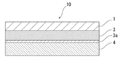
- the battery packaging material of the present invention comprises, for example, as shown in FIG. 1, a laminate having at least a base material layer 1, a barrier layer 3 and a heat fusible resin layer 4 in this order. It is done.
- the base material layer 1 is the outermost layer side
- the heat-fusible resin layer 4 is the innermost layer. That is, when assembling the battery, the battery element is sealed by sealing the battery element by thermally fusing the heat-fusible resin layers 4 located on the peripheral edge of the battery element.
- An acid resistant coating is provided on the surface of at least one side of the barrier layer 3.
- the acid resistant coating contains cerium.
- FIG. 1 the schematic diagram in the case where the battery packaging material of this invention equips the surface by the side of the heat fusible resin layer 4 of the barrier layer 3 with the acid-resistant film 3a is shown.
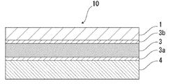
- FIG. 2 the schematic diagram in case the packaging material for batteries of this invention equips both surfaces of the barrier layer 3 with acid-resistant film 3a, 3b, respectively is shown.
- the acid resistant film 3 a may be provided only on the surface of the barrier layer 3 on the side of the heat fusible resin layer 4.
- the acid resistant coating 3 b may be provided only on the surface on the material layer 1 side, or the acid resistant coatings 3 a and 3 b may be provided on both surfaces of the barrier layer 3.
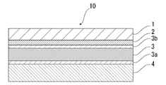
- the battery packaging material of the present invention is provided with an adhesive layer 2 between the base layer 1 and the barrier layer 3 as necessary for the purpose of enhancing the adhesiveness thereof.
- an adhesive layer 5 may be provided between the barrier layer 3 and the heat-fusible resin layer 4 as necessary for the purpose of enhancing the adhesiveness.
- the packaging material for a battery of the present invention is a barrier of the base material layer 1 as needed for the purpose of improving designability, electrolytic solution resistance, abrasion resistance, moldability, etc.
- a surface covering layer 6 may be provided on the side opposite to the layer 3 if necessary.
- the thickness of the laminate constituting the battery packaging material 10 of the present invention is not particularly limited. However, while the thickness of the battery packaging material is reduced to increase the energy density of the battery, the battery is excellent in formability. From the viewpoint of use as a packaging material, for example, about 180 ⁇ m or less, preferably about 150 ⁇ m or less, more preferably about 60 to 180 ⁇ m, further preferably about 60 to 150 ⁇ m.
- MD and TD in the manufacturing process can usually be discriminated for the barrier layer 3 described later.
- the barrier layer 3 is made of aluminum foil
- RD Rolling Direction
- linear streaks called so-called rolling marks are formed on the surface of the aluminum foil. Since the rolling marks extend along the rolling direction, the rolling direction of the aluminum foil can be grasped by observing the surface of the aluminum foil.
- the MD of the laminate and the RD of the aluminum foil coincide, so the surface of the aluminum foil of the laminate is observed to specify the rolling direction (RD) of the aluminum foil.
- the MD of the laminate can be identified.
- the TD of the laminate is perpendicular to the MD of the laminate, the TD of the laminate can also be specified.
- the base material layer 1 is a layer located on the outermost layer side. About the raw material which forms the base material layer 1, it does not restrict
- materials for forming the base material layer 1 include resins such as polyester resin, polyamide resin, epoxy resin, acrylic resin, fluorine resin, polyurethane resin, silicone resin, phenol resin, polycarbonate resin, and mixtures and copolymers thereof A film is mentioned. Among these, a polyester resin and a polyamide resin are preferably mentioned, and a biaxially stretched polyester resin and a biaxially stretched polyamide resin are more preferably mentioned.
- polyester resin examples include polyethylene terephthalate, polybutylene terephthalate, polyethylene naphthalate, polybutylene naphthalate, and copolyester.
- polyamide resin examples include nylon 6, nylon 66, a copolymer of nylon 6 and nylon 66, nylon 6, 10, polyamide MXD 6 (polymetaxylylene adipamide) and the like.
- the base material layer 1 may be formed of a resin film of one layer, but may be formed of a resin film of two or more layers in order to improve pinhole resistance and insulation. Specifically, a multilayer structure in which a polyester film and a nylon film are laminated, a multilayer structure in which a plurality of nylon films are laminated, a multilayer structure in which a plurality of polyester films are laminated, and the like can be mentioned.
- a laminate of a biaxially stretched nylon film and a biaxially stretched polyester film, a laminate of a plurality of biaxially stretched nylon films laminated, and a laminate of a plurality of biaxially stretched polyester films laminated Body is preferred.
- the base material layer 1 is formed of a resin film of two layers, a polyester resin and a polyester resin are laminated, a polyamide resin and a polyamide resin are laminated, or a polyester resin and a polyamide resin are laminated. It is more preferable to use a structure in which polyethylene terephthalate and polyethylene terephthalate are laminated, a structure in which nylon and nylon are laminated, or a structure in which polyethylene terephthalate and nylon are laminated. In addition, since the polyester resin is difficult to be discolored when, for example, the electrolyte solution adheres to the surface, it is preferable to laminate the base material layer 1 so that the polyester resin is positioned at the outermost layer in the laminated structure. When the base material layer 1 has a multilayer structure, the thickness of each layer is preferably about 2 to 25 ⁇ m.
- the base material layer 1 is formed of a multi-layered resin film
- two or more resin films may be laminated via an adhesive or an adhesive component such as an adhesive resin, and the type and amount of the adhesive component used, etc. Is similar to that of the adhesive layer 2 described later.
- limit especially as a method to laminate the resin film of two or more layers A well-known method can be adopted, for example, a dry laminating method, a sandwich laminating method, etc. are mentioned, Preferably a dry laminating method is mentioned.
- a urethane type adhesive is, for example, about 2 to 5 ⁇ m.
- a lubricant is preferably attached to the surface of the base layer 1.
- the lubricant is not particularly limited, but preferably includes amide lubricants.
- Specific examples of the amide-based lubricant include the same as those exemplified for the heat-fusible resin layer 4 described later.
- the amount thereof is not particularly limited, but it is preferably about 3 mg / m 2 or more, more preferably 4 to 5 in an environment of 24 ° C. and 60% relative humidity. It may be about 15 mg / m 2 , more preferably about 5 to 14 mg / m 2 .
- the base material layer 1 may contain a lubricant.
- the lubricant present on the surface of the substrate layer 1 may be one in which the lubricant contained in the resin constituting the substrate layer 1 is exuded, or the lubricant coated on the surface of the substrate layer 1 It may be
- the thickness of the base material layer 1 is not particularly limited as long as it exhibits the function as a base material layer, and for example, about 3 to 50 ⁇ m, preferably about 10 to 35 ⁇ m.
- the adhesive layer 2 is a layer provided between the substrate layer 1 and the barrier layer 3 as needed in order to firmly bond the substrate layer 1 and the barrier layer 3.
- the adhesive layer 2 is formed of an adhesive capable of adhering the base layer 1 and the barrier layer 3.
- the adhesive used to form the adhesive layer 2 may be a two-part curable adhesive, or may be a one-part curable adhesive.
- the adhesive used to form the adhesive layer 2 is not particularly limited, and may be any of a chemical reaction type, a solvent volatilization type, a heat melting type, a heat pressure type, and the like.
- polyester resins such as polyethylene terephthalate, polybutylene terephthalate, polyethylene naphthalate, polybutylene naphthalate, polyethylene isophthalate, copolyester, etc .
- Polyurethane resin Epoxy resin
- Phenolic resin resin Polycarbonate resin
- Polyamide resin such as nylon 6, nylon 66, nylon 12, copolymerized polyamide
- Polyolefin resin polyvinyl acetate resin; cellulose adhesive; (meth) acrylic resin; polyimide resin; amino resin such as urea resin, melamine resin; chloroprene rubber, nitrous resin - rubber, styrene rubbers such as butadiene rubber; and silicone resins.
- These adhesive components may be used alone or in combination of two or more.
- resin used as these adhesion components can improve adhesive strength together with a suitable hardening
- the curing agent is appropriately selected from polyisocyanate, polyfunctional epoxy resin, oxazoline group-containing polymer, polyamine resin, acid anhydride and the like according to the functional group of the adhesive component.
- polyurethane-based adhesives preferably composed of various polyols and polyisocyanates can be mentioned. More preferable examples include two-component polyurethane adhesives of which curing agents are aromatic or aliphatic polyisocyanates with polyols such as polyester polyols, polyether polyols, and acrylic polyols as main agents.
- the thickness of the adhesive layer 2 is not particularly limited as long as it exhibits the function as an adhesive layer, and for example, about 1 to 10 ⁇ m, preferably about 2 to 5 ⁇ m.
- the barrier layer 3 is a layer having a function to prevent water vapor, oxygen, light and the like from invading the inside of the battery, in addition to the strength improvement of the battery packaging material.
- the barrier layer 3 is preferably a metal layer, that is, a layer formed of a metal. Specifically as a metal which comprises the barrier layer 3, aluminum, stainless steel, titanium etc. are mentioned, Preferably aluminum is mentioned.
- the barrier layer 3 can be formed of, for example, a metal foil, a metal vapor deposited film, a film provided with these vapor deposited films, or the like, preferably formed of a metal foil, and more preferably formed of an aluminum alloy foil.
- the barrier layer is made of, for example, annealed aluminum (JIS H4160: 1994 A8021 H-O, JIS H4160: It is more preferable to use a soft aluminum alloy foil such as 1994 A8079 H-O, JIS H4000: 2014 A8021 P-O, JIS H 4000: 2014 A8079 P-O).
- the thickness of the barrier layer 3 is not particularly limited as long as it exhibits a function as a barrier layer such as water vapor, but from the viewpoint of reducing the thickness of the battery packaging material, it is preferably about 100 ⁇ m or less, more preferably 10 to It may be about 100 ⁇ m, more preferably about 10 to 80 ⁇ m.
- an acid resistant coating is provided on the surface of at least one side of the barrier layer 3.
- the acid-resistant film 3a may be provided only on the surface of the barrier layer 3 on the heat fusible resin layer 4 side, or the surface of the barrier layer 3 on the base layer 1 side.
- the acid resistant coating 3b may be provided only on the both sides, and the acid resistant coatings 3a and 3b may be provided on both sides of the barrier layer 3, respectively.
- the peak intensity P CePO4 derived from CePO 4 - is obtained .
- PO 3 - the ratio P PO3 / CePO4 the peak intensity P PO3 derived is characterized in that in the range of 80 to 120.
- the layer adjacent to the side provided with the acid-resistant film of the barrier layer 3 is also a layer even when the electrolytic solution adheres to the battery packaging material. It is excellent in adhesion with a short time.
- the barrier layer provided with the acid resistant coating can maintain high adhesion in a relatively short period of time (for example, about 2 to 5 years), and is used, for example, in mobile devices. Are particularly useful as packaging materials for small batteries.
- the peak intensity P CePO4 derived from CePO 4 - is obtained .
- PO 2 - the ratio P PO2 / CePO4 the peak intensity P PO2 derived is is characterized in that in the range of 90-150.
- the layer adjacent to the side provided with the acid resistant film of the barrier layer 3 is also a layer even when the electrolytic solution adheres to the battery packaging material It is excellent in adhesion with a short time.
- the barrier layer provided with the acid resistant coating can maintain high adhesion in a relatively short period of time, so it is small for use in, for example, mobile devices. It is particularly useful as a battery packaging material for
- the peak intensity ratio P PO3 of the acid resistant coating on any one surface is / CePO 4 or P PO 2 / CePO 4 may be within the above range (that is, in the case of the battery packaging material of the first aspect, the peak intensity ratio P PO 3 / CePO 4 is within the above range)
- the peak intensity ratio P PO2 / CePO4 may fall within the above range), but the peak intensity ratio P is the same for any of the acid resistant coatings 3a and 3b. It is preferable that PO 3 / CePO 4 or P PO 2 / CePO 4 be within the above range, respectively.
- an acid-resistant film located on the heat-fusion resin layer side of the barrier layer, and a layer adjacent thereto (for example, the adhesive layer 5 provided as needed, the heat-fusion resin layer 4 and the like)
- the acid-resistant film 3a is formed on the surface of the barrier layer 3 at least on the heat-fusible resin layer 4 side because the adhesion of the battery is likely to be reduced in a short time preferably be equipped, the peak intensity ratio P PO3 / CePO4 or P PO2 / CePO4 for acid-resistant film 3a, respectively, is preferably within the above range. About these points, it is the same also about each peak intensity ratio shown below.
- CePO 4 - PO 3 to the peak intensity P CePO4 derived from - the ratio P PO3 / CePO4 the peak intensity P PO3 derived is may be in the range of 80 to 120, the acid-resistant coating
- the lower limit of the ratio P PO3 / CePO 4 is preferably about 85 or more, more preferably about 92 or more, and the upper limit is preferably about about 2 or more, from the viewpoint of further improving the adhesion of the provided barrier layer in a short period of time. 110 or less, more preferably about 105 or less, still more preferably about 98 or less.
- the range of the peak intensity ratio P PO 3 / Ce PO 4 is preferably about 80 to 110, about 80 to 105, about 80 to 98, about 85 to 120, about 85 to 110, about 85 to 105, 85 to About 98, about 92 to 120, about 92 to 110, about 92 to 105, about 92 to 98, and the like.
- CePO 4 - PO 2 to the peak intensity P CePO4 derived from - the ratio P PO2 / CePO4 the peak intensity P PO2 derived is may be in the range of 90-150, acid resistance
- the lower limit of the ratio P PO 2 / Ce PO 4 is preferably about 110 or more, and the upper limit is preferably about 130 or less, more preferably from the viewpoint of enhancing the adhesion in a short period of time of the barrier layer provided with the film. Is about 116 or less.
- the range of the peak intensity ratio PPO2 / CePO4 is preferably about 90 to 130, about 90 to 116, about 110 to 150, about 110 to 130, about 110 to 116.
- the POO to the peak intensity P CePO4 derived from CePO 4 - is obtained . 2 - as the ratio P PO2 / CePO4 the peak intensity P PO2 derived from
- the lower limit is preferably about 90 or more can be mentioned
- the upper limit is preferably about 150 or less, or more preferably 130 or less.
- the range of the peak intensity ratio PPO2 / CePO4 in the first aspect is preferably about 90 to about 150, more preferably about 90 to about 130.
- the method of analyzing the acid resistant coatings 3a and 3b using time-of-flight secondary ion mass spectrometry should be performed under the following measurement conditions using a time-of-flight secondary ion mass spectrometer Can.
- the acid-resistant film contains cerium.
- the layers (adhesive layer, heat fusible resin layer, adhesive layer, etc.) laminated on the barrier layer are physically peeled off.
- the barrier layer is placed in an electric furnace, and the organic components present on the surface of the barrier layer are removed at about 300 ° C. for about 30 minutes. Thereafter, X-ray photoelectron spectroscopy of the surface of the barrier layer is used to confirm that cerium is contained.
- the acid resistant coatings 3a and 3b can be formed by chemical conversion treatment of the surface of the barrier layer 3 with a treatment solution containing a cerium compound such as cerium oxide.
- a chemical conversion treatment using a treatment liquid containing a cerium compound for example, one in which a cerium compound such as cerium oxide is dispersed in phosphoric acid and / or a salt thereof is applied to the surface of the barrier layer 3 and baked.
- a cerium compound such as cerium oxide is dispersed in phosphoric acid and / or a salt thereof is applied to the surface of the barrier layer 3 and baked.
- the peak intensity ratio PPO3 / CePO4 or PPO2 / CePO4 of the acid resistant films 3a and 3b is, for example, the composition of the treatment liquid for forming the acid resistant films 3a and 3b, and the production conditions such as the temperature and time of the baking treatment after the treatment. It can be adjusted by
- the ratio of the cerium compound to the phosphoric acid and / or the salt thereof in the treatment liquid containing the cerium compound is not particularly limited, but each of the above peak intensity ratios P PO3 / CePO4 or P PO2 / CePO4 is set within the above range. From the point of view, the ratio of phosphoric acid and / or a salt thereof to 100 parts by mass of the cerium compound is preferably about 12 to about 28, and more preferably about 15 to about 25 parts by mass.
- phosphoric acid and its salt for example, condensed phosphoric acid and its salt can also be used.
- the treatment liquid containing a cerium compound may further contain an anionic polymer and a crosslinking agent for crosslinking the anionic polymer.
- the anionic polymer include poly (meth) acrylic acid or a salt thereof, a copolymer containing (meth) acrylic acid or a salt thereof as a main component, and the like.
- a crosslinking agent the compound which has a functional group of an isocyanate group, a glycidyl group, a carboxyl group, and an oxazoline group, a silane coupling agent, etc. are mentioned.
- the anionic polymer and the crosslinking agent may each be of one type or of two or more types.
- the treatment liquid containing a cerium compound contains an aminated phenol polymer.
- the content of the aminated phenol polymer is preferably about 100 to 400 parts by mass, more preferably about 200 to 300 parts by mass, with respect to 100 parts by mass of the cerium compound.
- the weight-average molecular weight of the aminated phenol polymer is preferably about 5,000 to about 20,000.
- the weight average molecular weight of the aminated phenolic polymer is a value measured by gel permeation chromatography (GPC), which is measured under the condition of using polystyrene as a standard sample.
- the solvent of the treatment liquid containing the cerium compound is not particularly limited as long as it can disperse the components contained in the treatment liquid and evaporate by heating thereafter, but preferably includes water.
- the solid content concentration of the treatment liquid containing a cerium compound is, for example, about 8 to 30% by mass.
- the surface temperature of the barrier layer when applying the treatment liquid to the surface of the barrier layer and heating to form an acid resistant coating is preferably about 190 to 220 ° C., and the heating time is 3 to 6 There is about a second. By adopting such temperature and heating time, the solvent can be appropriately evaporated to form an acid resistant coating layer suitably.
- the solid content concentration of the cerium compound contained in the treatment liquid for forming the acid resistant coating is not particularly limited, but the peak intensity ratio PPO3 / CePO4 or PPO2 / CePO4 is set to the above-mentioned predetermined range, respectively.
- a solvent such as water
- the thickness of the acid resistant coating is not particularly limited, but preferably from about 1 nm to 10 ⁇ m, from the viewpoint of enhancing the adhesion of the barrier layer provided with the acid resistant coating in a short period of time while exhibiting excellent acid resistance. More preferably, it is about 1 to 100 nm, and more preferably about 1 to 50 nm.
- the thickness of the acid resistant coating can be measured by transmission electron microscopy or a combination of observation with a transmission electron microscope and energy dispersive X-ray spectroscopy or electron beam energy loss spectroscopy.
- the bar-coat method As a method of apply
- the peak strength ratio P PO3 / CePO4 or P PO2 / CePO4 is set to the above-described predetermined range to enhance the adhesion in a short period of time of the barrier layer provided with the acid resistant film while exhibiting excellent acid resistance.
- the heating temperature for baking the treatment solution to form an acid resistant coating is preferably about 170 to 250 ° C., more preferably about 180 to 220 ° C.
- the baking time is preferably about 2 to 10 seconds, more preferably about 3 to 6 seconds.
- an alkaline dipping method an electrolytic cleaning method, an acid cleaning method, an electrolytic acid cleaning method, an acid activity It is preferable to carry out the degreasing treatment by a known treatment method such as
- the thermally fusible resin layer 4 corresponds to the innermost layer, and is a layer that thermally fuses the thermally fusible resin layers when the battery is assembled to seal the battery element.
- the resin component used for the heat fusible resin layer 4 is not particularly limited as long as heat fusible is possible, and examples thereof include polyolefin, cyclic polyolefin, acid-modified polyolefin, and acid-modified cyclic polyolefin. That is, the resin constituting the heat-fusible resin layer 4 may or may not contain a polyolefin skeleton, and preferably contains a polyolefin skeleton.
- the resin constituting the heat-fusible resin layer 4 can be analyzed by, for example, infrared spectroscopy, gas chromatography-mass spectrometry, etc., as long as it contains a polyolefin skeleton, and the analysis method is not particularly limited.
- a peak derived from maleic acid is detected in the vicinity of the wave number of 1760 cm -1 and near the wave number 1780 cm -1.
- the peak may be small and not detected. In that case, analysis is possible by nuclear magnetic resonance spectroscopy.
- polystyrene resin examples include polyethylenes such as low density polyethylene, medium density polyethylene, high density polyethylene and linear low density polyethylene; homopolypropylene, block copolymers of polypropylene (for example, block copolymers of propylene and ethylene), polypropylene Polypropylenes such as random copolymers of (for example, random copolymers of propylene and ethylene); terpolymers of ethylene-butene-propylene and the like.
- polyethylenes such as low density polyethylene, medium density polyethylene, high density polyethylene and linear low density polyethylene
- homopolypropylene block copolymers of polypropylene (for example, block copolymers of propylene and ethylene)
- polypropylene Polypropylenes such as random copolymers of (for example, random copolymers of propylene and ethylene); terpolymers of ethylene-butene-propylene and the like.
- polyethylene and polypropylene are mentioned.
- the cyclic polyolefin is a copolymer of an olefin and a cyclic monomer, and examples of the olefin which is a constituent monomer of the cyclic polyolefin include ethylene, propylene, 4-methyl-1-pentene, butadiene, isoprene and the like. .
- a cyclic monomer which is a constituent monomer of the cyclic polyolefin for example, cyclic alkenes such as norbornene; specifically, cyclic dienes such as cyclopentadiene, dicyclopentadiene, cyclohexadiene, norbornadiene, and the like can be mentioned.
- these polyolefins preferred are cyclic alkenes, more preferably norbornene.
- the acid-modified polyolefin is a polymer modified by block copolymerization or graft copolymerization of the polyolefin with an acid component such as a carboxylic acid.
- an acid component such as a carboxylic acid.
- carboxylic acids such as maleic acid, acrylic acid, itaconic acid, crotonic acid, maleic anhydride, itaconic anhydride, or anhydrides thereof.
- the acid-modified cyclic polyolefin is prepared by copolymerizing part of the monomers constituting the cyclic polyolefin with an ⁇ , ⁇ -unsaturated carboxylic acid or an anhydride thereof, or ⁇ , ⁇ - to the cyclic polyolefin. It is a polymer obtained by block copolymerization or graft copolymerization of unsaturated carboxylic acid or its anhydride.
- the cyclic polyolefin to be carboxylic acid modified is the same as described above. Moreover, as a carboxylic acid used for modification
- polyolefins such as polypropylene, carboxylic acid-modified polyolefins, and more preferably polypropylene and acid-modified polypropylenes.
- the heat fusible resin layer 4 may be formed of one type of resin component alone, or may be formed of a blend polymer in which two or more types of resin components are combined. Furthermore, the heat-fusible resin layer 4 may be formed of only one layer, but may be formed of two or more layers of the same or different resin components.
- a lubricant adheres to the surface of the heat-fusible resin layer.
- the lubricant is not particularly limited, but preferably includes amide lubricants.
- Specific examples of the amide lubricant include saturated fatty acid amide, unsaturated fatty acid amide, substituted amide, methylolamide, saturated fatty acid bisamide, unsaturated fatty acid bisamide and the like.
- Specific examples of the saturated fatty acid amide include lauric acid amide, palmitic acid amide, stearic acid amide, behenic acid amide, hydroxystearic acid amide and the like.
- the unsaturated fatty acid amide include oleic acid amide and erucic acid amide.
- substituted amide include N-oleyl palmitic acid amide, N-stearyl stearic acid amide, N-stearyl oleic acid amide, N-oleyl stearic acid amide, N-stearyl erucic acid amide and the like.
- methylolamide include methylol stearic acid amide and the like.
- saturated fatty acid bisamide examples include methylenebisstearic acid amide, ethylenebiscapric acid amide, ethylenebislauric acid amide, ethylenebisstearic acid amide, ethylenebishydroxystearic acid amide, ethylenebisbehenic acid amide, hexamethylene bisstearin Acid amide, hexamethylene bisbehenamide, hexamethylene hydroxystearic amide, N, N'-distearyl adipamide, N, N'-distearyl sebacate amide and the like can be mentioned.
- unsaturated fatty acid bisamides include ethylene bis oleic acid amide, ethylene bis erucic acid amide, hexamethylene bis oleic acid amide, N, N'-dioleyl adipic acid amide, N, N'-dioleyl sebacic acid amide Etc.
- fatty acid ester amides include stearoamidoethyl stearate and the like.
- specific examples of the aromatic bisamides include m-xylylene bis-stearic acid amide, m-xylylene bis-hydroxystearic acid amide, N, N'-distearyl isophthalic acid amide and the like.
- the lubricant may be used alone or in combination of two or more.
- the amount thereof is not particularly limited, but it is preferably about 3 mg / m 2 or more, more preferably in an environment of 24 ° C. and 60% relative humidity. Is about 4 to 15 mg / m 2 , and more preferably about 5 to 14 mg / m 2 .
- the heat fusible resin layer 4 may contain a lubricant.
- the lubricant present on the surface of the heat-fusible resin layer 4 may be one in which the lubricant contained in the resin constituting the heat-fusible resin layer 4 is exuded, or the heat-fusible resin layer The surface of 4 may be coated with a lubricant.
- the thickness of the heat-fusible resin layer 4 is not particularly limited as long as it exhibits the function as a heat-fusible resin layer, but is preferably about 60 ⁇ m or less, more preferably about 15 to 60 ⁇ m, further preferably The thickness may be about 15 to 40 ⁇ m.
- Adhesive layer 5 In the battery packaging material of the present invention, the adhesive layer 5 is a layer optionally provided between the barrier layer 3 and the heat-fusible resin layer 4 in order to enhance the adhesion thereof. Adhesion layer 5 may be constituted by a single layer, and may be constituted by the same or different layers.
- the acid resistant coating has the above-mentioned specific peak intensity ratio, it is excellent in adhesion, and the acid resistant coating 3 a and the adhesive layer 5 The adhesion between them is also effectively enhanced.
- the acid-resistant film is provided in a mode in which the acid-resistant film 3 a on the surface of the barrier layer 3 and the heat-fusible resin layer 4 are laminated via the adhesive layer 5.
- the effect that the adhesion of the barrier layer is excellent can be exhibited particularly effectively.
- the adhesive layer 5 is formed of a resin capable of adhering the barrier layer 3 (further, the acid resistant coating 3 a) and the heat-fusible resin layer 4.
- resin used for formation of adhesion layer 5 the thing of the adhesion mechanism, the kind of adhesive agent component, etc. can use the thing similar to the adhesive illustrated by adhesive agent layer 2.
- polyolefin resin such as polyolefin mentioned above-mentioned heat-fusion resin layer 4
- cyclic polyolefin, carboxylic acid modified polyolefin, carboxylic acid modified cyclic polyolefin can also be used. .
- the polyolefin a carboxylic acid-modified polyolefin is preferable, and a carboxylic acid-modified polypropylene is particularly preferable, from the viewpoint of excellent adhesion between the barrier layer 3 and the heat-fusible resin layer 4. That is, the resin constituting the adhesive layer 5 may or may not contain a polyolefin skeleton, and preferably contains a polyolefin skeleton. It is possible to analyze that the resin constituting the adhesive layer 5 contains a polyolefin skeleton, for example, by infrared spectroscopy, gas chromatography mass spectrometry, etc., and there is no particular limitation on the analysis method.
- a peak derived from maleic acid is detected in the vicinity of the wave number of 1760 cm -1 and near the wave number 1780 cm -1.
- the peak may be small and not detected. In that case, analysis is possible by nuclear magnetic resonance spectroscopy.
- the adhesive layer 5 is a resin composition containing an acid-modified polyolefin and a curing agent. It may be a cured product.
- the acid-modified polyolefin preferably, the same ones as the carboxylic acid-modified polyolefin and the carboxylic acid-modified cyclic polyolefin exemplified in the heat fusible resin layer 4 can be exemplified.
- the curing agent is not particularly limited as long as it cures acid-modified polyolefin.
- examples of the curing agent include epoxy-based curing agents, polyfunctional isocyanate-based curing agents, carbodiimide-based curing agents, oxazoline-based curing agents, and the like.
- the epoxy curing agent is not particularly limited as long as it is a compound having at least one epoxy group.
- the epoxy curing agent include epoxy resins such as bisphenol A diglycidyl ether, modified bisphenol A diglycidyl ether, novolak glycidyl ether, glycerin polyglycidyl ether, polyglycerin polyglycidyl ether and the like.
- the polyfunctional isocyanate-based curing agent is not particularly limited as long as it is a compound having two or more isocyanate groups.
- Specific examples of the polyfunctional isocyanate-based curing agent include isophorone diisocyanate (IPDI), hexamethylene diisocyanate (HDI), tolylene diisocyanate (TDI), diphenylmethane diisocyanate (MDI), those obtained by polymerizing or denating these, or the like Mixtures and copolymers with other polymers may be mentioned.
- curing agent the polycarbodiimide compound which has a carbodiimide group 2 or more at least is preferable.
- the oxazoline-based curing agent is not particularly limited as long as it is a compound having an oxazoline skeleton (oxazoline group).
- Specific examples of the compound having an oxazoline group include those having a polystyrene main chain, and those having an acryl main chain.
- Specific examples of the oxazoline curing agent include Epocross series manufactured by Nippon Shokubai Co., Ltd.
- the curing agent may be composed of two or more types of compounds.
- the content of the curing agent in the resin composition forming the adhesive layer 5 is preferably in the range of about 0.1 to 50% by mass, and more preferably in the range of about 0.1 to 30% by mass, More preferably, it is in the range of about 0.1 to 10% by mass.
- the adhesive layer 5 is a cured product of a resin composition containing an acid-modified polyolefin, and at least one selected from the group consisting of a compound having an isocyanate group, a compound having an oxazoline group, and a compound having an epoxy group. Particularly preferred is a cured product of a resin composition containing an acid-modified polyolefin and at least one selected from the group consisting of a compound having an isocyanate group and a compound having an epoxy group.
- the adhesive layer 5 preferably contains at least one selected from the group consisting of a urethane resin, an ester resin, and an epoxy resin, and more preferably contains a urethane resin and an epoxy resin.
- ester resin an amide ester resin is preferable, for example.
- Amide ester resins are generally formed by the reaction of carboxyl groups with oxazoline groups.
- the adhesive layer 5 is more preferably a cured product of a resin composition containing at least one of these resins and the acid-modified polyolefin.
- the presence of the non-reacted substance is, for example, infrared spectroscopy, It can be confirmed by a method selected from Raman spectroscopy, time-of-flight secondary ion mass spectrometry (TOF-SIMS) and the like.
- a curing agent which has a heterocyclic ring the curing agent which has an oxazoline group, the curing agent which has an epoxy group, etc. are mentioned, for example.
- a curing agent having a C—O—C bond a curing agent having an oxazoline group, a curing agent having an epoxy group, a urethane resin and the like can be mentioned.
- That the adhesive layer 5 is a cured product of a resin composition containing these curing agents is, for example, gas chromatography mass spectrometry (GCMS), infrared spectroscopy (IR), time-of-flight secondary ion mass spectrometry (TOF) -SIMS), X-ray photoelectron spectroscopy (XPS), etc. can confirm.
- GCMS gas chromatography mass spectrometry
- IR infrared spectroscopy
- TOF time-of-flight secondary ion mass spectrometry
- XPS X-ray photoelectron spectroscopy
- the compound having an isocyanate group is not particularly limited, but from the viewpoint of effectively enhancing the adhesion between the acid resistant coating 3 a and the adhesive layer 5, a polyfunctional isocyanate compound is preferably mentioned.
- the polyfunctional isocyanate compound is not particularly limited as long as it is a compound having two or more isocyanate groups. The above-mentioned thing is mentioned as a specific example of a polyfunctional isocyanate type curing agent.
- the content of the compound having an isocyanate group in the adhesive layer 5 is preferably in the range of 0.1 to 50% by mass, and more preferably 0.5 to 40% by mass, in the resin composition constituting the adhesive layer 5. It is more preferable to be in the range. Thereby, the adhesion between the acid resistant film 3 a and the adhesive layer 5 can be effectively enhanced.
- the compound having an oxazoline group is not particularly limited as long as it is a compound having an oxazoline skeleton.
- Specific examples of the compound having an oxazoline group include those having a polystyrene main chain, and those having an acryl main chain. Moreover, the above-mentioned thing etc. are mentioned as a commercial item.
- the proportion of the compound having an oxazoline group in the adhesive layer 5 is preferably in the range of 0.1 to 50% by mass, and more preferably in the range of 0.5 to 40% by mass, in the resin composition constituting the adhesive layer 5. It is more preferable that Thereby, the adhesion between the acid resistant film 3 a and the adhesive layer 5 can be effectively enhanced.
- the epoxy resin is not particularly limited as long as it is a resin capable of forming a cross-linked structure by an epoxy group present in the molecule, and a known epoxy resin can be used.
- the weight average molecular weight of the epoxy resin is preferably about 50 to about 2000, more preferably about 100 to about 1000, and still more preferably about 200 to about 800.
- the weight average molecular weight of the epoxy resin is a value measured by gel permeation chromatography (GPC), which is measured under the condition of using polystyrene as a standard sample.
- the epoxy resin examples include glycidyl ether derivative of trimethylolpropane, bisphenol A diglycidyl ether, modified bisphenol A diglycidyl ether, novolac glycidyl ether, glycerin polyglycidyl ether, polyglycerin polyglycidyl ether and the like.
- the epoxy resin may be used alone or in combination of two or more.
- the proportion of the epoxy resin in the adhesive layer 5 is preferably in the range of 0.1 to 50% by mass, and more preferably in the range of 0.5 to 40% by mass, in the resin composition constituting the adhesive layer 5. Is more preferred. Thereby, the adhesion between the acid resistant film 3 a and the adhesive layer 5 can be effectively enhanced.
- an acid-modified polyolefin functions as a main agent, and a compound having an isocyanate group, a compound having an oxazoline group, and an epoxy resin each function as a curing agent.
- the thickness of the adhesive layer 5 is not particularly limited as long as it exhibits the function as an adhesive layer, but when using the adhesive exemplified in the adhesive layer 2, it is preferably about 1 to 10 ⁇ m, more preferably The order of 1 to 5 ⁇ m can be mentioned. Further, in the case of using the resin exemplified for the heat fusible resin layer 4, it is preferably about 2 to 50 ⁇ m, more preferably about 10 to 40 ⁇ m. In the case of a cured product of an acid-modified polyolefin and a curing agent, it is preferably about 30 ⁇ m or less, more preferably about 0.1 to 20 ⁇ m, and still more preferably about 0.5 to 5 ⁇ m. When the adhesive layer 5 is a cured product of a resin composition containing an acid-modified polyolefin and a curing agent, the adhesive layer 5 can be formed by applying the resin composition and curing it by heating or the like.
- the outer side of the base material layer 1 (the barrier layer of the base material layer 1 as needed) for the purpose of improving designability, electrolytic solution resistance, abrasion resistance, moldability, etc.
- a surface covering layer 6 may be provided on the side opposite to 3). When the surface covering layer 6 is provided, the surface covering layer 6 is the outermost layer of the battery packaging material.
- the surface coating layer 6 can be formed of, for example, polyvinylidene chloride, polyester resin, urethane resin, acrylic resin, epoxy resin or the like. Among these, the surface coating layer 6 is preferably formed of a two-component curable resin. Examples of the two-component curable resin that forms the surface covering layer 6 include a two-component curable urethane resin, a two-component curable polyester resin, and a two-component curable epoxy resin. Further, an additive may be blended in the surface coating layer.
- Examples of the additive include fine particles having a particle diameter of about 0.5 nm to 5 ⁇ m.
- the material of the additive is not particularly limited, and examples thereof include metals, metal oxides, inorganic substances, and organic substances.
- the shape of the additive is not particularly limited, and examples thereof include spheres, fibers, plates, indeterminate shapes, and balloons.
- talc silica, graphite, kaolin, montmorrroid, montmorillonite, synthetic mica, hydrotalcite, silica gel, zeolite, aluminum hydroxide, magnesium hydroxide, zinc oxide, magnesium oxide, aluminum oxide, Neodymium oxide, antimony oxide, titanium oxide, cerium oxide, calcium sulfate, barium sulfate, calcium carbonate, calcium silicate, lithium carbonate, calcium benzoate, calcium oxalate, magnesium stearate, alumina, carbon black, carbon nanotubes, high Melting point nylon, crosslinked acrylic, crosslinked styrene, crosslinked polyethylene, benzoguanamine, gold, aluminum, copper, nickel and the like can be mentioned.
- additives may be used alone or in combination of two or more.
- silica, barium sulfate and titanium oxide are preferably mentioned from the viewpoint of dispersion stability and cost.
- the surface may be subjected to various surface treatments such as insulation treatment, high dispersion treatment, and the like.
- the content of the additive in the surface coating layer 6 is not particularly limited, but preferably about 0.05 to 1.0% by mass, more preferably about 0.1 to 0.5% by mass.
- coating 2-component curable resin which forms a surface coating layer on the surface of the outer side of the base material layer 1 is mentioned.
- the additive may be added to and mixed with the two-component curable resin and then applied.
- the thickness of the surface coating layer 6 is not particularly limited as long as the above-described function as the surface coating layer 6 is exhibited, and for example, about 0.5 to 10 ⁇ m, preferably about 1 to 5 ⁇ m.
- the method for producing the battery packaging material of the present invention is not particularly limited as long as a laminate obtained by laminating each layer of a predetermined composition is obtained, and the battery packaging material of the first aspect
- the step of forming a laminate by laminating at least the base layer, the barrier layer, and the heat-fusible resin layer in this order, and laminating the barrier layer, on at least one side surface of the barrier layer comprises an oxidation-resistant film, the acid-resistant film, when analyzed using time-of-flight secondary ion mass spectrometry, CePO 4 - derived peak intensity P CePO4
- CePO 4 - derived peak intensity P CePO4 There is a method in which the ratio P PO3 / CePO4 of the peak intensity P PO3 derived from PO 3 - to P 3 is in the range of 80 to 120.
- the battery packaging material of the second aspect includes a step of laminating at least a base material layer 1, a barrier layer 3, and a heat-fusible resin layer 4 in this order, and the barrier layer from - when stacking, on at least one side surface of the barrier layer comprises an oxidation-resistant film, the acid-resistant film, when analyzed using time-of-flight secondary ion mass spectrometry, CePO 4 PO 2 to the peak intensity P CePO4 that - the ratio P PO2 / CePO4 the peak intensity P PO2 derived may be mentioned a method using what is in the range of 90-150.
- a laminate in which the base material layer 1, the adhesive layer 2 provided as necessary, and the barrier layer 3 are sequentially laminated is formed.
- the formation of the laminate A is used to form the adhesive layer 2 in the base layer 1 or the barrier layer 3 (when the acid resistant film 3 a is provided, the acid resistant film 3 a, hereinafter omitted)
- the adhesive is applied and dried by a coating method such as a gravure coating method or a roll coating method, and then the dry lamination method is performed in which the barrier layer 3 or the substrate layer 1 is laminated and the adhesive layer 2 is cured. it can.
- the formation method of acid-resistant film 3a, 3b is as above-mentioned.
- the heat fusible resin layer 4 is laminated on the barrier layer 3 of the laminate A.
- the resin component constituting the heat fusible resin layer 4 is gravure-coated or roll-coated on the barrier layer 3 of the laminate A It may be applied by a method such as When the adhesive layer 5 is provided between the barrier layer 3 and the heat fusible resin layer 4, for example, (1) the adhesive layer 5 and the heat fusible resin layer on the barrier layer 3 of the laminate A Method of laminating 4 by coextrusion (co-extrusion laminating method), (2) Separately, a laminated body in which the adhesive layer 5 and the heat-fusible resin layer 4 are laminated is formed, (3) A method of laminating by thermal laminating method, (3) A method of extruding or solution coating an adhesive for forming the adhesive layer 5 on the barrier layer 3 of the laminated body A, drying at a high temperature, and baking Method of laminating the thermally fusible resin layer
- the surface covering layer 6 When the surface covering layer 6 is provided, the surface covering layer is laminated on the surface of the base layer 1 opposite to the barrier layer 3.
- the surface coating layer can be formed, for example, by applying the above-mentioned resin forming the surface coating layer to the surface of the base material layer 1.
- the order of the step of laminating the barrier layer 3 on the surface of the base layer 1 and the step of laminating the surface coating layer on the surface of the base layer 1 is not particularly limited.
- the barrier layer 3 may be formed on the surface of the base material layer 1 opposite to the surface coating layer.
- the surface covering layer 6 / base layer 1 / optional layer 1 / optional adhesive layer 2 / at least one surface is provided with an acid resistant film / optional layer
- a laminate of the adhesive layer 5 / thermal adhesive resin layer 4 to be provided is formed, but in order to strengthen the adhesiveness of the adhesive layer 2 and the adhesive layer 5 to be provided if necessary, It may be subjected to heat treatment such as hot roll contact, hot air, near infrared, far infrared or the like.
- each layer constituting the laminate improves or stabilizes film forming ability, lamination processing, final product secondary processing (pouching, embossing) suitability, etc., as necessary.
- surface activation treatments such as corona treatment, blast treatment, oxidation treatment, and ozone treatment may be performed.
- the battery packaging material of the present invention is used for a package for sealing and housing battery elements such as a positive electrode, a negative electrode, and an electrolyte. That is, the battery element provided with at least a positive electrode, a negative electrode, and an electrolyte can be accommodated in a package formed of the battery packaging material of the present invention to make a battery.
- the aforementioned peak strength and the like can be analyzed by cutting out the battery packaging material from the battery.
- a sample is obtained from a portion, such as the top and bottom surfaces of the battery, from which the heat fusible resin layers are not heat-fused and subjected to analysis.
- a battery element comprising at least a positive electrode, a negative electrode, and an electrolyte is a battery packaging material of the present invention, in which the metal terminal connected to each of the positive electrode and the negative electrode protrudes outward.
- the battery is covered by forming flanges (areas in which the heat fusible resin layers are in contact with each other) on the periphery of the element, and heat sealing the heat fusible resin layers of the flanges to seal them.
- a battery using a packaging material is provided.
- the battery packaging material of the present invention may be used for either a primary battery or a secondary battery, but is preferably a secondary battery.
- the type of secondary battery to which the battery packaging material of the present invention is applied is not particularly limited.
- lithium ion battery, lithium ion polymer battery, lead storage battery, nickel hydrogen storage battery, nickel cadmium storage battery, nickel Iron storage batteries, nickel-zinc storage batteries, silver oxide-zinc storage batteries, metal air batteries, multivalent cation batteries, capacitors, capacitors and the like can be mentioned.
- lithium ion batteries and lithium ion polymer batteries are mentioned as a suitable application object of the packaging material for batteries of the present invention.
- the barrier layer provided with the acid resistant coating can maintain high adhesion in a relatively short period of time. Therefore, the battery packaging material of the present invention is particularly useful, for example, as a packaging material for small batteries used in mobile devices and the like.
- Example 1 As a base material layer, polyethylene terephthalate and nylon were laminated by coextrusion, and a biaxially stretched laminated film was prepared.
- a resin containing a modified thermoplastic resin graft-modified with an unsaturated carboxylic acid derivative component between a biaxially stretched polyethylene terephthalate film (thickness 5 ⁇ m) and a biaxially stretched nylon film (thickness 20 ⁇ m) It is adhered by an adhesive layer (adhesive, 1 ⁇ m thick) using the composition.
- two layers of the barrier layer comprising an aluminum foil (JIS H4160: 1994 A8021 H-O, thickness 40 ⁇ m) provided with an acid resistant coating (thickness 20 nm) are subjected to chemical conversion treatment on both sides by a method described later.
- the film was laminated on the surface of the axially stretched nylon film by dry lamination. Specifically, a two-component urethane adhesive (polyol compound and aromatic isocyanate compound) was applied to one surface of an aluminum foil provided with an acid resistant film to form an adhesive layer (3 ⁇ m in thickness).
- an adhesive (3 ⁇ m in thickness after curing) consisting of a non-crystalline polyolefin resin having a carboxyl group and a polyfunctional isocyanate compound is applied as an adhesive layer on the surface of the acid resistant film of the obtained laminate. , Dried.
- an unstretched laminated polypropylene film random polypropylene (thickness 5 ⁇ m) / block polypropylene (thickness 30 ⁇ m) / random polypropylene (thickness 5 ⁇ m), total thickness
- the adhesive layer / heat-sealable resin layer was laminated on the barrier layer by laminating 40 ⁇ m) and passing through and bonding between two heated rolls.
- the obtained laminate is cured (aging) to obtain a biaxially stretched polyethylene terephthalate film (5 ⁇ m) / adhesive (1 ⁇ m) / biaxially stretched nylon film (20 ⁇ m) / adhesive layer (3 ⁇ m) / both sides
- a battery packaging material is obtained in which a barrier layer (40 ⁇ m) / adhesive layer (3 ⁇ m) / unstretched laminated polypropylene film (40 ⁇ m) provided with an acid resistant film (thickness 20 nm) is laminated in this order.
- the acid-resistant film on the surface of the barrier layer contains 20 parts by mass of an inorganic phosphorus compound (sodium phosphate) with 100 parts by mass of cerium oxide (water as a solvent is contained, and the solid concentration is Prepare a solution of about 10% by mass), and apply the treatment solution on both sides of the barrier layer (film thickness after drying is 20 nm), and the surface temperature of the barrier layer is about 190 to 230 ° C., 3 to 6 It was formed by heating and drying for about a second.
- an inorganic phosphorus compound sodium phosphate
- cerium oxide water as a solvent is contained
- Example 2 An unstretched laminated polypropylene film (random polypropylene (thickness 10 ⁇ m) / block polypropylene (thickness 60 ⁇ m) / random polypropylene (a thickness of 60 ⁇ m) instead of the unstretched laminated polypropylene film (thickness 40 ⁇ m) as a heat fusible resin layer Biaxially stretched polyethylene terephthalate film (5 ⁇ m) / adhesive (1 ⁇ m) / biaxially stretched nylon film (20 ⁇ m) / in the same manner as in Example 1 except that a thickness of 10 ⁇ m) and a total thickness of 80 ⁇ m) were used.
- Random polypropylene (thickness 10 ⁇ m) / block polypropylene (thickness 60 ⁇ m) / random polypropylene (a thickness of 60 ⁇ m) instead of the unstretched laminated polypropylene film (thickness 40 ⁇ m) as a heat fusible resin layer
- the aluminum foil as a barrier layer used what was equipped with the same acid-resistant film as Example 1.
- an adhesive (3 ⁇ m in thickness after curing) consisting of a non-crystalline polyolefin resin having a carboxyl group and a polyfunctional isocyanate compound is applied as an adhesive layer on the surface of the acid resistant film of the obtained laminate. , Dried.
- unstretched laminated polypropylene film random polypropylene (4 ⁇ m thick) / block polypropylene (22 ⁇ m thick) / random polypropylene (4 ⁇ m thick
- total as the first heat-welding resin layer total 30 .mu.m thick
- the formation of the acid resistant coating on the surface of the barrier layer was performed as follows.
- a treatment liquid containing 43 parts by mass of aminated phenolic polymer, 16 parts by mass of chromium fluoride and 13 parts by mass of phosphoric acid with respect to 100 parts of water is easily applied, and the treatment liquid is applied to both sides of the barrier layer (after drying)
- the film is heated and dried for about 3 to 6 seconds at a temperature at which the surface temperature of the barrier layer is about 190 to 230.degree. C.
- Comparative example 2 A biaxially stretched nylon film (20 ⁇ m) / in the same manner as Comparative Example 1 except that random polypropylene (20 ⁇ m thick) was extruded instead of random polypropylene (50 ⁇ m thick) as the heat fusible resin layer.
- a laminated battery packaging material was obtained.
- the aluminum foil as a barrier layer used what was equipped with the same acid-resistant film as the comparative example 1.
- Example 1 the formation of the acid-resistant film on the surface of the barrier layer is about half (mass ratio) of the phosphoric acid in Example 1 in Comparative Example 3 and about 1.5 in Example 3 in Comparative Example 4.
- a packaging material for a battery was obtained in the same manner as in Example 1, except that the treatment was carried out so as to be about double (mass ratio).
- the analysis of the acid resistant film was performed as follows. First, the space between the barrier layer and the adhesive layer was peeled off. Under the present circumstances, it was made to exfoliate physically, without using the water, the organic solvent, and the aqueous solution of an acid and an alkali. After peeling between the barrier layer and the adhesive layer, since the adhesive layer remained on the surface of the barrier layer, the remaining adhesive layer was removed by etching with Ar-GCIB. With respect to the surface of the barrier layer thus obtained, analysis of the acid resistant film was conducted using time-of-flight secondary ion mass spectrometry.
- Measurement device ION-TOF time-of-flight secondary ion mass spectrometer TOF.
- SIMS 5 Measurement conditions
- Primary ion Double charge ion of bismuth cluster (Bi 3 ++ )
- Primary ion acceleration voltage 30 kV Mass range (m / z): 0 to 1500 Measurement range: 100 ⁇ m ⁇ 100 ⁇ m Number of scans: 16 scan / cycle Number of pixels (one side): 256 pixels
- Etching ion Ar gas cluster ion beam (Ar-GCIB) Etching ion acceleration voltage: 5.0 kV
- each battery packaging material obtained above was cut into a size of 15 mm (TD: Transverse Direction, horizontal direction) and 100 mm (MD: Machine Direction, vertical direction) to obtain test pieces.
- the glass bottle was covered and sealed.
- the sealed glass bottle was placed in an oven set at 85 ° C. and allowed to stand for 24 hours.
- the glass bottle was taken out of the oven, the test piece was further taken out of the glass bottle, washed with water, and the water on the surface of the test piece was wiped off with a towel.
- the heat fusible resin layer of the test piece and the barrier layer are peeled off, and the heat fusible resin layer side and the barrier layer side of the test piece are subjected to a tensile testing machine (trade name AGS-XPlus manufactured by Shimadzu Corporation).
- the peeling distance (N / 15 mm) of the test piece was measured by pulling in the direction of 180 ° at a speed of 50 mm / min with a distance between marked lines of 50 mm, using a marked line distance.
- the measurement of the peeling strength of a test piece was performed within 10 minutes, after wiping off the water
- initial adhesion was evaluated as follows. First, the battery packaging materials obtained in Examples 1 and 2 and Comparative Examples 1 to 4 were cut into test pieces of 15 mm (TD) and 100 mm (MD). Next, the heat fusible resin layer of the test piece and the barrier layer are peeled off, and the heat fusible resin layer and the barrier layer are marked using a tensile tester (trade name AGS-XPlus manufactured by Shimadzu Corporation). Between the distance of 50 mm, it was pulled in the direction of 180 ° at a speed of 50 mm / min, and the peel strength (N / 15 mm) of the test piece was measured to obtain initial adhesion. The results are shown in Table 1. When the heat fusible resin layer and the barrier layer are separated, the adhesive layer located between these layers is in a state of being laminated on either or both of the heat fusible resin layer and the barrier layer. It becomes.
- the surface of the barrier layer comprises an oxidation-resistant film, the acid-resistant film, when analyzed using time-of-flight secondary ion mass spectrometry, CePO 4 - to PO 3 for derived peak intensity P CePO4 - the ratio P PO3 / CePO4 from the peak intensity P PO3 is, the battery packaging material of example 1 and 2 are within the range of 80 to 120, the surface of the barrier layer It can be seen that, despite the provision of the acid-resistant coating, the adhesion between the barrier layer and the heat-fusible resin layer is excellent after immersion in the electrolytic solution.
- the battery packaging material of Example 1 and 2, CePO 4 - PO 2 to the peak intensity P CePO4 derived from - the ratio P PO2 / CePO4 the peak intensity P PO2 derived is in the range of 90-150
- the adhesion between the barrier layer and the heat-sealable resin layer was excellent.
Landscapes
- Chemical & Material Sciences (AREA)
- Chemical Kinetics & Catalysis (AREA)
- Electrochemistry (AREA)
- General Chemical & Material Sciences (AREA)
- Engineering & Computer Science (AREA)
- Power Engineering (AREA)
- Microelectronics & Electronic Packaging (AREA)
- Sealing Battery Cases Or Jackets (AREA)
- Laminated Bodies (AREA)
Priority Applications (2)
| Application Number | Priority Date | Filing Date | Title |
|---|---|---|---|
| JP2018558788A JP6485609B1 (ja) | 2017-07-19 | 2018-07-19 | 電池用包装材料、電池用包装材料の製造方法、及び電池 |
| CN201880003701.7A CN109792008B (zh) | 2017-07-19 | 2018-07-19 | 电池用包装材料、电池用包装材料的制造方法和电池 |
Applications Claiming Priority (2)
| Application Number | Priority Date | Filing Date | Title |
|---|---|---|---|
| JP2017-139814 | 2017-07-19 | ||
| JP2017139814 | 2017-07-19 |
Publications (1)
| Publication Number | Publication Date |
|---|---|
| WO2019017456A1 true WO2019017456A1 (ja) | 2019-01-24 |
Family
ID=65016291
Family Applications (1)
| Application Number | Title | Priority Date | Filing Date |
|---|---|---|---|
| PCT/JP2018/027187 Ceased WO2019017456A1 (ja) | 2017-07-19 | 2018-07-19 | 電池用包装材料、電池用包装材料の製造方法、及び電池 |
Country Status (3)
| Country | Link |
|---|---|
| JP (2) | JP6485609B1 (enExample) |
| CN (1) | CN109792008B (enExample) |
| WO (1) | WO2019017456A1 (enExample) |
Cited By (3)
| Publication number | Priority date | Publication date | Assignee | Title |
|---|---|---|---|---|
| WO2020153457A1 (ja) * | 2019-01-23 | 2020-07-30 | 大日本印刷株式会社 | 全固体電池及びその製造方法 |
| JP2020119755A (ja) * | 2019-01-23 | 2020-08-06 | 大日本印刷株式会社 | 蓄電デバイス用外装材、蓄電デバイス用外装材の製造方法、及び蓄電デバイス |
| JP2020119756A (ja) * | 2019-01-23 | 2020-08-06 | 大日本印刷株式会社 | 蓄電デバイス用外装材、蓄電デバイス用外装材の製造方法、及び蓄電デバイス |
Citations (3)
| Publication number | Priority date | Publication date | Assignee | Title |
|---|---|---|---|---|
| WO2012050182A1 (ja) * | 2010-10-14 | 2012-04-19 | 凸版印刷株式会社 | リチウムイオン電池用外装材 |
| WO2017065223A1 (ja) * | 2015-10-15 | 2017-04-20 | 凸版印刷株式会社 | 蓄電装置用外装材、及びそれを用いた蓄電装置 |
| WO2017073774A1 (ja) * | 2015-10-28 | 2017-05-04 | 大日本印刷株式会社 | 電池用包装材料、電池、電池用包装材料の製造方法、及びアルミニウム合金箔 |
Family Cites Families (4)
| Publication number | Priority date | Publication date | Assignee | Title |
|---|---|---|---|---|
| JP5211622B2 (ja) * | 2007-01-31 | 2013-06-12 | 凸版印刷株式会社 | リチウム電池用包材およびその製造方法 |
| WO2014178343A1 (ja) * | 2013-05-01 | 2014-11-06 | 大倉工業株式会社 | 電池外包材 |
| WO2016158796A1 (ja) * | 2015-03-27 | 2016-10-06 | 大日本印刷株式会社 | 電池用包装材料、その製造方法及び電池 |
| WO2016159190A1 (ja) * | 2015-03-30 | 2016-10-06 | 大日本印刷株式会社 | 電池用包装材料、その製造方法及び電池 |
-
2018
- 2018-07-19 WO PCT/JP2018/027187 patent/WO2019017456A1/ja not_active Ceased
- 2018-07-19 CN CN201880003701.7A patent/CN109792008B/zh active Active
- 2018-07-19 JP JP2018558788A patent/JP6485609B1/ja active Active
-
2019
- 2019-02-20 JP JP2019028707A patent/JP7151538B2/ja active Active
Patent Citations (3)
| Publication number | Priority date | Publication date | Assignee | Title |
|---|---|---|---|---|
| WO2012050182A1 (ja) * | 2010-10-14 | 2012-04-19 | 凸版印刷株式会社 | リチウムイオン電池用外装材 |
| WO2017065223A1 (ja) * | 2015-10-15 | 2017-04-20 | 凸版印刷株式会社 | 蓄電装置用外装材、及びそれを用いた蓄電装置 |
| WO2017073774A1 (ja) * | 2015-10-28 | 2017-05-04 | 大日本印刷株式会社 | 電池用包装材料、電池、電池用包装材料の製造方法、及びアルミニウム合金箔 |
Cited By (8)
| Publication number | Priority date | Publication date | Assignee | Title |
|---|---|---|---|---|
| WO2020153457A1 (ja) * | 2019-01-23 | 2020-07-30 | 大日本印刷株式会社 | 全固体電池及びその製造方法 |
| JP2020119755A (ja) * | 2019-01-23 | 2020-08-06 | 大日本印刷株式会社 | 蓄電デバイス用外装材、蓄電デバイス用外装材の製造方法、及び蓄電デバイス |
| JP2020119756A (ja) * | 2019-01-23 | 2020-08-06 | 大日本印刷株式会社 | 蓄電デバイス用外装材、蓄電デバイス用外装材の製造方法、及び蓄電デバイス |
| JP2020202188A (ja) * | 2019-01-23 | 2020-12-17 | 大日本印刷株式会社 | 全固体電池及びその製造方法 |
| JP7225832B2 (ja) | 2019-01-23 | 2023-02-21 | 大日本印刷株式会社 | 蓄電デバイス用外装材、蓄電デバイス用外装材の製造方法、及び蓄電デバイス |
| JP7225833B2 (ja) | 2019-01-23 | 2023-02-21 | 大日本印刷株式会社 | 蓄電デバイス用外装材、蓄電デバイス用外装材の製造方法、及び蓄電デバイス |
| JP7443989B2 (ja) | 2019-01-23 | 2024-03-06 | 大日本印刷株式会社 | 全固体電池及びその製造方法 |
| US12500296B2 (en) | 2019-01-23 | 2025-12-16 | Dai Nippon Printing Co., Ltd. | All-solid-state battery and method for manufacturing same |
Also Published As
| Publication number | Publication date |
|---|---|
| JP7151538B2 (ja) | 2022-10-12 |
| CN109792008B (zh) | 2021-03-02 |
| JPWO2019017456A1 (ja) | 2019-07-18 |
| JP6485609B1 (ja) | 2019-03-20 |
| JP2019117795A (ja) | 2019-07-18 |
| CN109792008A (zh) | 2019-05-21 |
Similar Documents
| Publication | Publication Date | Title |
|---|---|---|
| JP7468715B2 (ja) | 電池用包装材料、電池用包装材料の製造方法、及び電池 | |
| JP7405225B2 (ja) | 電池用包装材料、その製造方法、及び電池 | |
| JP7622810B2 (ja) | 蓄電デバイス用外装材、その製造方法、及び蓄電デバイス | |
| JP6628009B2 (ja) | 電池用包装材料、その製造方法、及び電池 | |
| JP7056810B1 (ja) | 全固体電池用外装材、その製造方法、及び全固体電池 | |
| CN113348081B (zh) | 蓄电器件用外包装材料、蓄电器件用外包装材料的制造方法和蓄电器件 | |
| JP7314970B2 (ja) | 電池用包装材料、その製造方法及び電池 | |
| JP7225832B2 (ja) | 蓄電デバイス用外装材、蓄電デバイス用外装材の製造方法、及び蓄電デバイス | |
| JPWO2020027333A1 (ja) | 蓄電デバイス用外装材、その製造方法、及び蓄電デバイス | |
| CN111279509A (zh) | 电池用包装材料和电池 | |
| JP6485609B1 (ja) | 電池用包装材料、電池用包装材料の製造方法、及び電池 | |
| JP6736837B2 (ja) | 電池用包装材料 | |
| JPWO2017188445A1 (ja) | 電池用包装材料及び電池 | |
| JP2020119709A (ja) | 蓄電デバイス、蓄電デバイス用外装部材、蓄電デバイス集合体、電動自動車及び蓄電デバイスの製造方法 | |
| JP2020119710A (ja) | 蓄電デバイス、蓄電デバイス用外装部材、蓄電デバイス集合体、電動自動車及び蓄電デバイスの製造方法 | |
| JP7225833B2 (ja) | 蓄電デバイス用外装材、蓄電デバイス用外装材の製造方法、及び蓄電デバイス | |
| JP7452438B2 (ja) | 蓄電デバイス用外装材、蓄電デバイス用外装材の製造方法、及び蓄電デバイス | |
| CN111512463A (zh) | 电池用包装材料和电池 | |
| JP2024179301A (ja) | 蓄電デバイス用外装材、その製造方法、及び蓄電デバイス |
Legal Events
| Date | Code | Title | Description |
|---|---|---|---|
| ENP | Entry into the national phase |
Ref document number: 2018558788 Country of ref document: JP Kind code of ref document: A |
|
| 121 | Ep: the epo has been informed by wipo that ep was designated in this application |
Ref document number: 18834572 Country of ref document: EP Kind code of ref document: A1 |
|
| NENP | Non-entry into the national phase |
Ref country code: DE |
|
| 122 | Ep: pct application non-entry in european phase |
Ref document number: 18834572 Country of ref document: EP Kind code of ref document: A1 |