WO2019016906A1 - 構造体の製造方法 - Google Patents
構造体の製造方法 Download PDFInfo
- Publication number
- WO2019016906A1 WO2019016906A1 PCT/JP2017/026166 JP2017026166W WO2019016906A1 WO 2019016906 A1 WO2019016906 A1 WO 2019016906A1 JP 2017026166 W JP2017026166 W JP 2017026166W WO 2019016906 A1 WO2019016906 A1 WO 2019016906A1
- Authority
- WO
- WIPO (PCT)
- Prior art keywords
- coil
- tubular member
- manufacturing
- beam member
- fixing
- Prior art date
- Legal status (The legal status is an assumption and is not a legal conclusion. Google has not performed a legal analysis and makes no representation as to the accuracy of the status listed.)
- Ceased
Links
Images






Classifications
-
- B—PERFORMING OPERATIONS; TRANSPORTING
- B21—MECHANICAL METAL-WORKING WITHOUT ESSENTIALLY REMOVING MATERIAL; PUNCHING METAL
- B21D—WORKING OR PROCESSING OF SHEET METAL OR METAL TUBES, RODS OR PROFILES WITHOUT ESSENTIALLY REMOVING MATERIAL; PUNCHING METAL
- B21D39/00—Application of procedures in order to connect objects or parts, e.g. coating with sheet metal otherwise than by plating; Tube expanders
- B21D39/06—Application of procedures in order to connect objects or parts, e.g. coating with sheet metal otherwise than by plating; Tube expanders of tubes in openings, e.g. rolling-in
-
- B—PERFORMING OPERATIONS; TRANSPORTING
- B21—MECHANICAL METAL-WORKING WITHOUT ESSENTIALLY REMOVING MATERIAL; PUNCHING METAL
- B21D—WORKING OR PROCESSING OF SHEET METAL OR METAL TUBES, RODS OR PROFILES WITHOUT ESSENTIALLY REMOVING MATERIAL; PUNCHING METAL
- B21D39/00—Application of procedures in order to connect objects or parts, e.g. coating with sheet metal otherwise than by plating; Tube expanders
- B21D39/08—Tube expanders
Definitions
- the present invention relates to a method of manufacturing a structure in which another member is attached to the outer periphery of a tubular member made of a metal tube.
- steel members are often used in terms of cost and workability such as welding. From the demand for improvement of fuel consumption in recent years, it has been practiced to replace a part of steel members with a lightweight member, and it is considered to apply such a lightweight member to a frame member as well as a panel member. There is.
- An aluminum alloy is preferably used as such a lightweight structural member.
- the frame member when the bracket member is welded and fixed to the frame member, the frame member may be thermally deformed by heat at the time of welding. Therefore, as a fixing method for suppressing thermal deformation at the time of welding, fixing by caulking the bracket member on the outer peripheral side is considered by expanding the tubular member.
- the technique of the above-mentioned patent documents 1 is energized to the coil which penetrated the full length of a tubular member, and it expands a tubular member over full length, and the technique of patent documents 2 inserts in the both ends of a tubular member.
- the coil is energized to expand the ends of the tubular member.
- the object of the present invention is to provide a method for manufacturing a tubular member, which can easily manufacture a structure in which other members are fixed at a plurality of locations in the axial intermediate portion. There is.
- the present invention has the following constitution.
- the present invention has the following constitution.
- a manufacturing method of a structure in which other members are respectively attached to a plurality of axial attachment positions of a tubular member made of a metal tube A member disposing step of disposing the other member at the mounting position of the tubular member by inserting the tubular member into a mounting hole formed in the other member; Inserting a coil unit, in which a plurality of coils are axially connected by a support rod, from the end of the tubular member to the inside; A coil arrangement step of moving the coil unit and arranging each of the coils at a position corresponding to the mounting position; A coil fixing step of restricting axial movement of each of the coils by fixing the support rods extending to the outside of the tubular member; Affixing step of expanding the attachment position of each of the tubular members by electromagnetic force generated by energizing each of the coils, and affixing the plurality of other members to the tubular member; A method of manufacturing a structure comprising: In addition, the coil disposing step, the
- FIG. 1 is a perspective view of a reinforcement which is an example of a structure.
- the reinforcement 1 has a beam member 2 which is a tubular member, and a bracket member 3 which is another member provided on the outer periphery of the beam member 2.
- the beam member 2 is formed in a long cylindrical shape.
- a fixing member 4 for fixing the reinforcement 1 to the body of the vehicle and a support member 5 for supporting the steering on the reinforcement 1 are fixed to the beam member 2.
- the beam member 2 is a nonmagnetic metal pipe, and is, for example, an extruded material made of aluminum or an aluminum alloy.
- the bracket member 3 is fixed to, for example, a member constituting an instrument panel.
- the bracket member 3 is formed of a metal material such as aluminum or an aluminum alloy, and is, for example, a cast or wrought material.
- the bracket member 3 is not limited to aluminum or aluminum alloy, and may be another metal material, or may be formed of a hard resin material.
- the bracket member 3 is integrally provided on the outer periphery of the beam member 2.
- the fixed position of the bracket member 3 of the beam member 2 is an enlarged diameter portion 6 whose diameter is expanded outward in the radial direction.
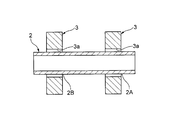
- FIG. 2 is process explanatory drawing explaining a member arrangement
- the beam member 2 before forming the enlarged diameter portion 6 is prepared, and the beam member 2 is inserted into the mounting hole 3 a formed in the bracket member 3.
- the bracket member 3 is disposed at a predetermined mounting position in the axial direction on the outer periphery of the beam member 2.
- the bracket member 3 is arrange
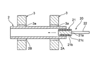
- FIG. 3 is a process explanatory view for explaining the insertion process, and is a schematic cross-sectional view along the axial direction of the beam member.
- the coil 21 is inserted into the beam member 2 from the end of the beam member 2.
- the coil 21 includes a bobbin portion 21a and a conductor wire 21b.
- the bobbin portion 21a is formed of an insulating resin in a rod-like shape, and a conductor wire 21b is wound around the bobbin portion 21a.
- the conductor wire 21b has a rectangular or square cross-sectional shape, and the periphery thereof is covered with the insulating material 21c.
- the coil 21 is fixed to the end of the support bar 22.
- the support rod 22 is formed of a rigid rod, and for example, a pipe made of a synthetic resin is used.
- the coil unit 20 is configured of the coil 21 and the support rod 22.
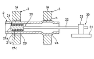
- FIG. 4 is a process explanatory view for explaining a coil arranging process, and is a schematic cross-sectional view along the axial direction of the beam member.
- the coil unit 20 is moved in the axial direction, and the coil 21 inserted into the beam member 2 is disposed at a position corresponding to the mounting position to which the bracket member 3 is fixed.
- the coil 21 is disposed at a position corresponding to the mounting position of the first enlarged diameter portion 2A near the end of the beam member 2 into which the coil 21 is inserted.
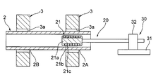
- FIG. 5 is process explanatory drawing explaining a coil fixing process, and is a schematic sectional drawing in alignment with the axial direction of a beam member.
- the fixing tool 30 has a fixing base 31 fixed to a table (not shown) for fixing the beam member 2 and a fastening portion 32 for fastening the support bar 22. Then, by fastening the support rod 22 with the fixture 30, the coil 21 is fixed in a state of being disposed at a position corresponding to the mounting position inside the beam member 2, and the movement in the axial direction is restricted. .
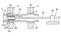
- FIG. 6 is a process explanatory view for explaining the fixing process, and is a schematic cross-sectional view along the axial direction of the beam member.
- a large current is instantaneously supplied to the coil 21 to generate an electromagnetic force.
- the location of the coil 21 in the beam member 2 is expanded radially outward by the electromagnetic force to form the enlarged diameter portion 6.
- the outer periphery of the first enlarged diameter portion 2A of the beam member 2 is crimped to the bracket member 3 and fixed.
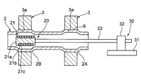
- FIG. 7 is a process explanatory view for explaining a coil arranging process, and is a schematic cross-sectional view along the axial direction of the beam member.
- the fastening of the support rod 22 by the fixture 30 is released, and the coil unit 20 is moved in the axial direction.
- the coil 21 inside the beam member 2 is disposed at a position corresponding to the mounting position in the second enlarged diameter portion 2B, which is the next mounting position to which the bracket member 3 is fixed.
- FIG. 8 is a process explanatory view for explaining a coil fixing process, and is a schematic cross-sectional view along an axial direction of a beam member.
- the support rods 22 of the coil unit 20 extending to the outside of the beam member 2 are fastened by the fixing tool 30 outside the beam member 2 to fix the coil 21, and in the axial direction of the coil 21. Restrict the movement of
- FIG. 9 is a process explanatory view for explaining the fixing process, and is a schematic cross-sectional view along the axial direction of the beam member.
- a large current is instantaneously supplied to the coil 21 to generate an electromagnetic force.
- the location of the coil 21 in the beam member 2 is expanded radially outward by the electromagnetic force to form the enlarged diameter portion 6.
- the bracket member 3 is crimped and fixed to the outer periphery of the second enlarged diameter portion 2B of the beam member 2.
- the bracket members 3 are disposed at the plurality of attachment positions of the beam member 2, and the coil 21 is inserted from the end of the beam member 2.
- the above-mentioned coil arrangement step, coil fixing step and fixing step are repeatedly performed in order for each mounting position.
- the reinforcement 1 in which the bracket members 3 are fixed to the plurality of attachment positions of the beam members 2 which are individually expanded can be obtained.
- the beam 21 is moved by moving the coil 21 of the coil unit 20 inserted into the beam 2 in the axial direction to expand the beam 2 by electromagnetic forming at each mounting position.
- the bracket member 3 can be fixed to a plurality of axial positions of two. As a result, for example, the bracket members 3 can be easily fixed to a plurality of locations in the axial middle portion of the long beam member 2 such as the vehicle reinforcement 1 or the like.
- the support rod 22 is fixed outside the beam member 2 to restrict the axial movement of the coil 21 before the coil 21 is energized and electromagnetically molded, the beam member 2 is expanded smoothly without positional deviation.
- the bracket member 3 can be crimped and fixed.
- the beam member 2 is expanded by electromagnetic forming.
- a hydraulic forming method for expanding the beam member 2 by the pressure of the liquid filled inside the beam member 2 or filling the gas inside the beam member 2 and applying pressure to the beam member 2
- a blow molding method for expanding a tube.
- the present method can partially expand the mounting position of the beam member 2 as compared with these methods.
- the seal structure for preventing the leakage of the liquid and the gas and the processing operation of the liquid and the gas after the molding can be eliminated, and the expansion position and the expansion range of the beam member 2 can be easily adjusted.
- a plurality of divided bodies divided in the circumferential direction are disposed inside the beam member 2, and the wedge is inserted at the center of the arrangement of the divided bodies to expand the divided bodies radially outward and the beam member 2 inside
- a mechanical molding method that can be pushed out of the In this method, as compared with this mechanical forming method, the pipe can be expanded uniformly, and there is no need to perform a cleaning operation for cleaning the lubricating oil after the pipe expansion.
- the beam member 2 before forming the enlarged diameter portion 6 is prepared, and the beam member 2 is inserted into the mounting hole 3 a formed in the bracket member 3. Then, the bracket member 3 is disposed at the attachment position in the axial direction on the outer periphery of the beam member 2. Thereby, the bracket member 3 is arrange
- FIG. 10 is a process explanatory view for explaining the insertion process, and is a schematic cross-sectional view along the axial direction of the beam member.
- a plurality of coils 21 are inserted into the beam member 2 from the end of the beam member 2.
- the coils 21 are axially connected by a support bar 22.
- the coil unit 20A is configured of the coil 21 and the support rod 22.
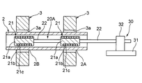
- FIG. 11 is a process explanatory view for explaining a coil arranging process, and is a schematic cross-sectional view along an axial direction of a beam member.
- the coil unit 20A is moved in the axial direction, and the coils 21 inserted into the beam member 2 are disposed at positions corresponding to the mounting positions to which the bracket member 3 is fixed.
- the coil 21 is disposed at a position corresponding to the mounting position of the first enlarged diameter portion 2A and at a position corresponding to the mounting position of the second enlarged diameter portion 2B.
- FIG. 12 is a process explanatory view for explaining a coil fixing process, and is a schematic cross-sectional view along an axial direction of a beam member.
- the support rod 22 of the coil unit 20A extending to the outside of the beam member 2 is fastened by the fixing tool 30 outside the beam member 2 to fix the coil 21 and to the axial direction of the coil 21. Restrict the movement of
- FIG. 13 is a process explanatory view for explaining the fixing process of the manufacturing method, and is a schematic cross-sectional view along the axial direction of the beam member.
- a large current is instantaneously supplied to the coils 21 to generate an electromagnetic force.
- the location of the coil 21 in the beam member 2 is expanded radially outward by the electromagnetic force to form the enlarged diameter portion 6.
- the outer peripheries of the first enlarged diameter portion 2A and the second enlarged diameter portion 2B of the beam member 2 are respectively caulked and fixed to the bracket member 3.
- the reinforcement 1 in which the bracket members 3 are fixed to the plurality of attachment positions of the beam members 2 which are individually expanded can be obtained.
- the bracket member 3 can be fixed to a plurality of locations in the axial direction of the beam member 2 while the coil unit 20A is fixed.
- the bracket members 3 can be easily fixed to a plurality of locations in the axial middle portion of the long beam member 2 such as the vehicle reinforcement 1 or the like.
- the support rod 22 is fixed outside the beam member 2 to restrict the axial movement of the coil 21 before the coil 21 is energized and electromagnetically molded, the beam member 2 is expanded smoothly without positional deviation.
- the bracket member 3 can be crimped and fixed.
- the beam member 2 is expanded by electromagnetic forming, so that the mounting position of the beam member 2 is partially expanded as compared with the hydraulic forming method or the flow forming method.
- the seal structure for preventing the leakage of the liquid and the gas and the processing operation of the liquid and the gas after the molding can be eliminated, and the expansion position and the expansion range of the beam member 2 can be easily adjusted.
- the pipe can be expanded uniformly, and there is no need to perform a cleaning operation for cleaning the lubricating oil after the pipe expansion.
- the beam member 2 is expanded by a plurality of coils 21 and caulked and fixed to the bracket member 3 at a plurality of mounting positions, and then the bracket member 3 is fixed to another mounting position.
- the coil disposing step, the coil fixing step, and the fixing step may be repeated.
- the beam member 2 can be expanded at a plurality of attachment positions by the plurality of coils 21 of the coil unit 20A inserted into the beam member 2. Furthermore, by moving the coil unit 20A in the axial direction and expanding the plurality of other attachment positions of the beam member 2 with the plurality of coils 21, the bracket member 3 can be extremely easily provided at a plurality of axial locations of the beam member 2. And it can fix in a short time.
- the bracket member 3 may be fixed by expanding a plurality of portions of the beam member 2 with the coil unit 20A having the coils 21 with different outer diameters.
- the first coil 21 of the coil unit 20A is disposed in the first enlarged diameter portion 2A of the beam member 2
- the second coil 21 of the coil unit 20A is disposed in the second enlarged diameter portion 2B of the beam member 2.
- electromagnetic forming thereby, the first expanded diameter portion 2A and the second expanded diameter portion 2B of the beam member 2 can be expanded in a well-balanced manner.
- the inserting step, the coil disposing step, the coil fixing step and the fixing step may be performed from both end sides of the beam member 2.
- the bracket members 3 can be extremely easily and in a short time at plural places in the axial direction of the beam member 2 Can be fixed.
- a pipe made of resin may be used as the support rod 22 of the coil units 20 and 20A used in the method of manufacturing the first and second structures.
- cooling air can be supplied to the coil 21 through the inside of the support bar 22, or a wire for energizing the coil 21 can be passed through the support bar 22.
- a bulging mechanism may be provided on the support rod 22. If the bulging mechanism is provided on the support bar 22, the bulging mechanism is made to squeeze in contact with the inner peripheral surface of the beam member 2 so that the support bar 22 is reliably held inside the beam member 2. Can. Further, the axial movement of the coil 21 at the time of electromagnetic forming can be more reliably restricted.
- the present invention is not limited to the above-described embodiment, and those skilled in the art can change or apply the components of the embodiment in combination with one another, based on the description of the specification, and based on known techniques. It is also the intention of the present invention to be included in the scope for which protection is sought.
- the coil of the coil unit inserted in the tubular member is moved in the axial direction to expand the tubular member by electromagnetic forming at each mounting position, so that plural places in the axial direction of the tubular member
- Other members can be secured.
- other members can be easily fixed to a plurality of places in the axial middle portion.
- the support rod is fixed outside the tubular member to restrict the axial movement of the coil before the coil is energized and electromagnetically molded, the tubular member is expanded smoothly without displacement and other members are removed. It can be fixed by caulking.
- Other members can be fixed to a plurality of locations in the axial direction. Thereby, for example, with respect to a long tubular member such as a vehicle reinforcement, other members can be easily fixed to a plurality of places in the axial middle portion.
- the support rod is fixed outside the tubular member to restrict the axial movement of the coil before the coil is energized and electromagnetically molded, the tubular member is expanded smoothly without any positional deviation, and so on without any positional deviation.
- Members can be crimped and fixed.
- the plurality of attachment positions of the tubular member can be expanded by the plurality of coils of the coil unit inserted into the tubular member. Furthermore, by moving the coil unit in the axial direction and expanding the other plural attachment positions of the tubular member by the plural coils, the other members can be extremely easily and quickly formed at plural places in the axial direction of the tubular member. It can be fixed.
Landscapes
- Engineering & Computer Science (AREA)
- Mechanical Engineering (AREA)
- Body Structure For Vehicles (AREA)
Abstract
構造体の製造方法においては、ブラケット部材の取付孔にビーム部材を挿通させてビーム部材の取付位置にブラケット部材を配置する。コイルユニットのコイルをビーム部材の端部から内部に挿し込む。コイルユニットのコイルを取付位置に対応する位置に配置させる。支持棒を固定することでコイルの軸方向移動を規制する。コイルに通電してビーム部材を拡管させ、ビーム部材にブラケット部材を固着させる。これらのコイル配置工程、コイル固定工程、及び固着工程を、それぞれの取付位置において順に行う。
Description
本発明は、金属管からなる管状部材の外周に他の部材が取り付けられた構造体の製造方法に関する。
自動車の部品は、コストや溶接などの施工性の観点から鋼部材が多く用いられている。近年の燃費の向上の要求から、鋼部材の一部を軽量な部材で置き換えることが行われており、パネル部材の他、フレーム部材にもそのような軽量化部材を適用することが検討されている。このような軽量構造部材としては、アルミニウム合金が好適に用いられる。
ところで、フレーム部材にブラケット部材を溶接して固着すると、溶接時の熱によってフレーム部材が熱変形するおそれがある。このため、溶接時の熱変形を抑止する固着方法として、管状部材を拡管させることで、その外周側のブラケット部材を固着させるかしめによる固着が検討されている。
このかしめによる固着方法としては、管状部材の内部に配置させたコイルに通電することで発生する電磁力により管状部材を拡管させ、外周側のブラケットを固着させる電磁成形がある(例えば、特許文献1,2参照)。
ところで、上記特許文献1の技術は、管状部材の全長にわたって通したコイルに通電して管状部材を全長にわたって拡管させるものであり、また、特許文献2の技術は、管状部材の両端部に挿し込んだコイルに通電して管状部材の両端部を拡管させるものである。
このため、特許文献1,2の技術では、例えば、車両のインストルメントパネル内に設けられるレインフォースなどの長尺の管状部材の軸方向の中間部分における複数箇所を個別に拡管させてブラケット部材などを固着させることは困難であった。
このため、特許文献1,2の技術では、例えば、車両のインストルメントパネル内に設けられるレインフォースなどの長尺の管状部材の軸方向の中間部分における複数箇所を個別に拡管させてブラケット部材などを固着させることは困難であった。
本発明は、管状部材に対して、その軸方向の中間部分における複数箇所に他の部材が固着された構造体を容易に製造することが可能な構造体の製造方法を提供することを目的としている。
本発明は下記構成からなる。
金属管からなる管状部材の軸方向の複数の取付位置に他の部材がそれぞれ取り付けられた構造体の製造方法であって、
前記他の部材に形成された取付孔に前記管状部材を挿通させて前記管状部材の前記取付位置に前記他の部材を配置する部材配置工程と、
支持棒にコイルが連結されたコイルユニットの前記コイルを前記管状部材の端部から内部に挿し込む挿入工程と、
前記コイルユニットを軸方向へ移動させて前記コイルを前記取付位置に対応する位置に配置させるコイル配置工程と、
前記管状部材の外部に延在する前記支持棒を固定することで前記コイルの軸方向の移動を規制するコイル固定工程と、
前記コイルに通電することで発生する電磁力により前記管状部材を拡管させ、前記管状部材に前記他の部材を固着させる固着工程と、
を含み、
前記コイル配置工程、前記コイル固定工程及び前記固着工程を、それぞれの前記取付位置において順に行うことを特徴とする構造体の製造方法。
また、本発明は下記構成からなる。
金属管からなる管状部材の軸方向の複数の取付位置に他の部材がそれぞれ取り付けられた構造体の製造方法であって、
前記他の部材に形成された取付孔に前記管状部材を挿通させて前記管状部材の前記取付位置に前記他の部材を配置する部材配置工程と、
複数のコイルが支持棒で軸方向に連結されたコイルユニットを前記管状部材の端部から内部に挿し込む挿入工程と、
前記コイルユニットを移動させ、それぞれの前記コイルを前記取付位置に対応する位置に配置させるコイル配置工程と、
前記管状部材の外部に延在する前記支持棒を固定することでそれぞれの前記コイルの軸方向の移動を規制するコイル固定工程と、
それぞれの前記コイルに通電することで発生する電磁力により前記管状部材のそれぞれの取付位置を拡管させ、前記管状部材に複数の前記他の部材を固着させる固着工程と、
を含むことを特徴とする構造体の製造方法。
また、前記コイル配置工程、前記コイル固定工程及び前記固着工程を繰り返すことであってもよい。
また、前記挿入工程、前記コイル配置工程、前記コイル固定工程及び前記固着工程を、前記管状部材の両端側から行うことであってもよい。
金属管からなる管状部材の軸方向の複数の取付位置に他の部材がそれぞれ取り付けられた構造体の製造方法であって、
前記他の部材に形成された取付孔に前記管状部材を挿通させて前記管状部材の前記取付位置に前記他の部材を配置する部材配置工程と、
支持棒にコイルが連結されたコイルユニットの前記コイルを前記管状部材の端部から内部に挿し込む挿入工程と、
前記コイルユニットを軸方向へ移動させて前記コイルを前記取付位置に対応する位置に配置させるコイル配置工程と、
前記管状部材の外部に延在する前記支持棒を固定することで前記コイルの軸方向の移動を規制するコイル固定工程と、
前記コイルに通電することで発生する電磁力により前記管状部材を拡管させ、前記管状部材に前記他の部材を固着させる固着工程と、
を含み、
前記コイル配置工程、前記コイル固定工程及び前記固着工程を、それぞれの前記取付位置において順に行うことを特徴とする構造体の製造方法。
また、本発明は下記構成からなる。
金属管からなる管状部材の軸方向の複数の取付位置に他の部材がそれぞれ取り付けられた構造体の製造方法であって、
前記他の部材に形成された取付孔に前記管状部材を挿通させて前記管状部材の前記取付位置に前記他の部材を配置する部材配置工程と、
複数のコイルが支持棒で軸方向に連結されたコイルユニットを前記管状部材の端部から内部に挿し込む挿入工程と、
前記コイルユニットを移動させ、それぞれの前記コイルを前記取付位置に対応する位置に配置させるコイル配置工程と、
前記管状部材の外部に延在する前記支持棒を固定することでそれぞれの前記コイルの軸方向の移動を規制するコイル固定工程と、
それぞれの前記コイルに通電することで発生する電磁力により前記管状部材のそれぞれの取付位置を拡管させ、前記管状部材に複数の前記他の部材を固着させる固着工程と、
を含むことを特徴とする構造体の製造方法。
また、前記コイル配置工程、前記コイル固定工程及び前記固着工程を繰り返すことであってもよい。
また、前記挿入工程、前記コイル配置工程、前記コイル固定工程及び前記固着工程を、前記管状部材の両端側から行うことであってもよい。
本発明の構造体の製造方法によれば、管状部材に対して、その軸方向の中間部分における複数箇所に他の部材が固着された構造体を容易に製造することができる。
以下、本発明の実施形態について、図面を参照して詳細に説明する。
<第1の構造体の製造方法>
まず、第1の構造体の製造方法について説明する。
図1は、構造体の一例であるレインフォースの斜視図である。
まず、第1の構造体の製造方法について説明する。
図1は、構造体の一例であるレインフォースの斜視図である。
ここでの構造体は、自動車等の車両のインストルメントパネル内に設けられるレインフォース1を一例として説明するが、これに限らない。
図1に示すように、レインフォース1は、管状部材であるビーム部材2と、このビーム部材2の外周に設けられた他の部材であるブラケット部材3とを有している。ビーム部材2は、長尺筒状に形成されている。このビーム部材2には、レインフォース1を車両のボディに固定するための固定部材4及びレインフォース1にステアリングを支持させる支持部材5が固定される。
このビーム部材2は、非磁性体の金属管であり、例えば、アルミニウムまたはアルミニウム合金からなる押出材である。ブラケット部材3は、例えば、インストルメントパネルを構成する部材等に固定される。ブラケット部材3は、アルミニウムまたはアルミニウム合金などの金属材料から形成されたもので、例えば、鋳物あるいは展伸材である。なお、ブラケット部材3としては、アルミニウムまたはアルミニウム合金に限らず他の金属材料であってもよく、また、硬質樹脂材料から形成されたものでもよい。ブラケット部材3は、ビーム部材2の外周に一体的に設けられている。ビーム部材2は、ブラケット部材3の固着箇所が、径方向外方へ拡径された拡径部6とされている。
次に、ビーム部材2の外周に複数のブラケット部材3が設けられた上記構造のレインフォース1を製造する本実施形態に係る製造方法を、その工程毎に説明する。
(部材配置工程)
図2は、部材配置工程を説明する工程説明図で、ビーム部材の軸方向に沿う概略断面図である。
図2に示すように、拡径部6を成形する前のビーム部材2を用意し、このビーム部材2をブラケット部材3に形成された取付孔3aに挿通させる。そして、ビーム部材2の外周における軸方向に関する所定の取付位置にブラケット部材3を配置する。そして、このビーム部材2の第一拡径部2A及び第二拡径部2Bの外周の取付位置にブラケット部材3を配置する。
図2は、部材配置工程を説明する工程説明図で、ビーム部材の軸方向に沿う概略断面図である。
図2に示すように、拡径部6を成形する前のビーム部材2を用意し、このビーム部材2をブラケット部材3に形成された取付孔3aに挿通させる。そして、ビーム部材2の外周における軸方向に関する所定の取付位置にブラケット部材3を配置する。そして、このビーム部材2の第一拡径部2A及び第二拡径部2Bの外周の取付位置にブラケット部材3を配置する。
(挿入工程)
図3は挿入工程を説明する工程説明図で、ビーム部材の軸方向に沿う概略断面図である。
図3に示すように、ビーム部材2の内部に、ビーム部材2の端部からコイル21を挿し込む。このコイル21は、ボビン部21aと導体素線21bとを備えている。ボビン部21aは絶縁性樹脂を棒状に形成したもので、このボビン部21aの周囲に導体素線21bが巻回されている。導体素線21bは、矩形または正方形の断面形状を有しており、その周囲は、絶縁性物質21cで覆われている。コイル21は、支持棒22の端部に固着されている。支持棒22は、剛性を有する棒体からなるもので、例えば、合成樹脂からなるパイプが用いられる。そして、このコイル21と支持棒22とから、コイルユニット20が構成されている。
図3は挿入工程を説明する工程説明図で、ビーム部材の軸方向に沿う概略断面図である。
図3に示すように、ビーム部材2の内部に、ビーム部材2の端部からコイル21を挿し込む。このコイル21は、ボビン部21aと導体素線21bとを備えている。ボビン部21aは絶縁性樹脂を棒状に形成したもので、このボビン部21aの周囲に導体素線21bが巻回されている。導体素線21bは、矩形または正方形の断面形状を有しており、その周囲は、絶縁性物質21cで覆われている。コイル21は、支持棒22の端部に固着されている。支持棒22は、剛性を有する棒体からなるもので、例えば、合成樹脂からなるパイプが用いられる。そして、このコイル21と支持棒22とから、コイルユニット20が構成されている。
(コイル配置工程)
図4は、コイル配置工程を説明する工程説明図で、ビーム部材の軸方向に沿う概略断面図である。
図4に示すように、コイルユニット20を軸方向へ移動させ、ビーム部材2の内部に挿入したコイル21を、ブラケット部材3を固着させる取付位置に対応する位置に配置させる。具体的には、コイル21を挿入したビーム部材2の端部に近い第一拡径部2Aにおける取付位置に対応する位置に配置させる。
図4は、コイル配置工程を説明する工程説明図で、ビーム部材の軸方向に沿う概略断面図である。
図4に示すように、コイルユニット20を軸方向へ移動させ、ビーム部材2の内部に挿入したコイル21を、ブラケット部材3を固着させる取付位置に対応する位置に配置させる。具体的には、コイル21を挿入したビーム部材2の端部に近い第一拡径部2Aにおける取付位置に対応する位置に配置させる。
(コイル固定工程)
図5は、コイル固定工程を説明する工程説明図で、ビーム部材の軸方向に沿う概略断面図である。
図5に示すように、ビーム部材2の外部に延在するコイルユニット20の支持棒22を、ビーム部材2の外部で固定具30によって締結する。固定具30は、ビーム部材2を固定するテーブル(図示略)に固定される固定台31と、支持棒22を締結する締結部32とを有している。そして、この固定具30によって支持棒22を締結することで、コイル21は、ビーム部材2の内部における取付位置に対応した位置に配置された状態で固定され、軸方向への移動が規制される。
図5は、コイル固定工程を説明する工程説明図で、ビーム部材の軸方向に沿う概略断面図である。
図5に示すように、ビーム部材2の外部に延在するコイルユニット20の支持棒22を、ビーム部材2の外部で固定具30によって締結する。固定具30は、ビーム部材2を固定するテーブル(図示略)に固定される固定台31と、支持棒22を締結する締結部32とを有している。そして、この固定具30によって支持棒22を締結することで、コイル21は、ビーム部材2の内部における取付位置に対応した位置に配置された状態で固定され、軸方向への移動が規制される。
(固着工程)
図6は、固着工程を説明する工程説明図で、ビーム部材の軸方向に沿う概略断面図である。
図6に示すように、コイルユニット20のコイル21に通電することで、このコイル21に瞬間的に大電流を流して電磁力を発生させる。これにより、この電磁力によってビーム部材2におけるコイル21の配置箇所を径方向外方へ拡管させて拡径部6を形成する。これにより、このビーム部材2の第一拡径部2Aにおける外周をブラケット部材3にかしめて固着する。
図6は、固着工程を説明する工程説明図で、ビーム部材の軸方向に沿う概略断面図である。
図6に示すように、コイルユニット20のコイル21に通電することで、このコイル21に瞬間的に大電流を流して電磁力を発生させる。これにより、この電磁力によってビーム部材2におけるコイル21の配置箇所を径方向外方へ拡管させて拡径部6を形成する。これにより、このビーム部材2の第一拡径部2Aにおける外周をブラケット部材3にかしめて固着する。
(コイル配置工程)
図7は、コイル配置工程を説明する工程説明図で、ビーム部材の軸方向に沿う概略断面図である。
図7に示すように、固定具30による支持棒22の締結を解除し、コイルユニット20を軸方向へ移動させる。そして、ビーム部材2の内部のコイル21を、ブラケット部材3を固着させる次の取付位置である第二拡径部2Bにおける取付位置に対応する位置に配置させる。
図7は、コイル配置工程を説明する工程説明図で、ビーム部材の軸方向に沿う概略断面図である。
図7に示すように、固定具30による支持棒22の締結を解除し、コイルユニット20を軸方向へ移動させる。そして、ビーム部材2の内部のコイル21を、ブラケット部材3を固着させる次の取付位置である第二拡径部2Bにおける取付位置に対応する位置に配置させる。
(コイル固定工程)
図8は、コイル固定工程を説明する工程説明図で、ビーム部材の軸方向に沿う概略断面図である。
図8に示すように、ビーム部材2の外部に延在するコイルユニット20の支持棒22を、ビーム部材2の外部で固定具30によって締結してコイル21を固定し、コイル21の軸方向への移動を規制させる。
図8は、コイル固定工程を説明する工程説明図で、ビーム部材の軸方向に沿う概略断面図である。
図8に示すように、ビーム部材2の外部に延在するコイルユニット20の支持棒22を、ビーム部材2の外部で固定具30によって締結してコイル21を固定し、コイル21の軸方向への移動を規制させる。
(固着工程)
図9は、固着工程を説明する工程説明図で、ビーム部材の軸方向に沿う概略断面図である。
図9に示すように、コイルユニット20のコイル21に通電することで、このコイル21に瞬間的に大電流を流して電磁力を発生させる。これにより、この電磁力によってビーム部材2におけるコイル21の配置箇所を径方向外方へ拡管させて拡径部6を形成する。これにより、このビーム部材2の第二拡径部2Bにおける外周にブラケット部材3をかしめて固着する。
図9は、固着工程を説明する工程説明図で、ビーム部材の軸方向に沿う概略断面図である。
図9に示すように、コイルユニット20のコイル21に通電することで、このコイル21に瞬間的に大電流を流して電磁力を発生させる。これにより、この電磁力によってビーム部材2におけるコイル21の配置箇所を径方向外方へ拡管させて拡径部6を形成する。これにより、このビーム部材2の第二拡径部2Bにおける外周にブラケット部材3をかしめて固着する。
このように、第1の構造体の製造方法では、ビーム部材2の複数の取付位置にそれぞれブラケット部材3を配置させ、ビーム部材2の端部からコイル21を挿し込む。その後、それぞれの取付位置に対して、上記のコイル配置工程、コイル固定工程及び固着工程を順に繰り返し行う。これにより、ビーム部材2の個別に拡管させた複数の取付位置にブラケット部材3がそれぞれ固着されたレインフォース1が得られる。
この第1の構造体の製造方法によれば、ビーム部材2に挿入したコイルユニット20のコイル21を軸方向に移動させて各取付位置で電磁成形によってビーム部材2を拡管させることで、ビーム部材2の軸方向の複数箇所にブラケット部材3を固着することができる。これにより、例えば、車両用のレインフォース1などのような長尺のビーム部材2に対して、その軸方向の中間部分における複数箇所にブラケット部材3を容易に固着させることができる。
また、コイル21に通電して電磁成形する前に支持棒22をビーム部材2の外部で固定してコイル21の軸方向への移動を規制させるので、位置ずれなく円滑にビーム部材2を拡管させてブラケット部材3をかしめて固着させることができる。
また、第1の構造体の製造方法では、電磁成形によってビーム部材2を拡管させている。例えば、ビーム部材2の内部に充填した液体の圧力によってビーム部材2を拡管させる液圧成形方式(ハイドロフォーム方式)やビーム部材2の内部に気体を充填して圧力を付与してビーム部材2を拡管させるブロー成形方式がある。本方法は、これらの方式と比較して、ビーム部材2の取付位置を部分的に拡管させることができる。また、液体や気体の漏れを防ぐためのシール構造及び成形後の液体や気体の処理作業を不要にでき、しかも、ビーム部材2における拡管位置や拡管範囲を容易に調整することができる。また、周方向に分割された複数の分割体をビーム部材2の内部に配置し、分割体の配置の中心に楔を挿し込むことで分割体を径方向外方へ広げてビーム部材2を内部から押し広げる機械成形方式もある。本方法は、この機械成形方式と比較して、均等に拡管することができ、また、拡管後に潤滑油を洗浄する洗浄作業などを行う必要もない。
<第2の構造体の製造方法>
次に、第2の構造体の製造方法ついて説明する。なお、上記第1の構造体の製造方法と同一構成部分は同一符号を付して説明を省略する。
次に、第2の構造体の製造方法ついて説明する。なお、上記第1の構造体の製造方法と同一構成部分は同一符号を付して説明を省略する。
(部材配置工程)
拡径部6を成形する前のビーム部材2を用意し、このビーム部材2をブラケット部材3に形成された取付孔3aに挿通させる。そして、ビーム部材2の外周における軸方向の取付位置にブラケット部材3を配置する。これにより、このビーム部材2の第一拡径部2A及び第二拡径部2Bの外周の取付位置にブラケット部材3を配置する(図2参照)。
拡径部6を成形する前のビーム部材2を用意し、このビーム部材2をブラケット部材3に形成された取付孔3aに挿通させる。そして、ビーム部材2の外周における軸方向の取付位置にブラケット部材3を配置する。これにより、このビーム部材2の第一拡径部2A及び第二拡径部2Bの外周の取付位置にブラケット部材3を配置する(図2参照)。
(挿入工程)
図10は、挿入工程を説明する工程説明図で、ビーム部材の軸方向に沿う概略断面図である。
図10に示すように、ビーム部材2の内部に、ビーム部材2の端部から複数のコイル21を挿し込む。これらのコイル21は、支持棒22によって軸方向に連結されている。そして、これらのコイル21と支持棒22とから、コイルユニット20Aが構成されている。
図10は、挿入工程を説明する工程説明図で、ビーム部材の軸方向に沿う概略断面図である。
図10に示すように、ビーム部材2の内部に、ビーム部材2の端部から複数のコイル21を挿し込む。これらのコイル21は、支持棒22によって軸方向に連結されている。そして、これらのコイル21と支持棒22とから、コイルユニット20Aが構成されている。
(コイル配置工程)
図11は、コイル配置工程を説明する工程説明図で、ビーム部材の軸方向に沿う概略断面図である。
図11に示すように、コイルユニット20Aを軸方向へ移動させ、ビーム部材2の内部に挿入した各コイル21を、ブラケット部材3を固着させる取付位置に対応する位置にそれぞれ配置させる。具体的には、第一拡径部2Aにおける取付位置に対応する位置及び第二拡径部2Bにおける取付位置に対応する位置にそれぞれコイル21を配置させる。
図11は、コイル配置工程を説明する工程説明図で、ビーム部材の軸方向に沿う概略断面図である。
図11に示すように、コイルユニット20Aを軸方向へ移動させ、ビーム部材2の内部に挿入した各コイル21を、ブラケット部材3を固着させる取付位置に対応する位置にそれぞれ配置させる。具体的には、第一拡径部2Aにおける取付位置に対応する位置及び第二拡径部2Bにおける取付位置に対応する位置にそれぞれコイル21を配置させる。
(コイル固定工程)
図12は、コイル固定工程を説明する工程説明図で、ビーム部材の軸方向に沿う概略断面図である。
図12に示すように、ビーム部材2の外部に延在するコイルユニット20Aの支持棒22を、ビーム部材2の外部で固定具30によって締結してコイル21を固定し、コイル21の軸方向への移動を規制させる。
図12は、コイル固定工程を説明する工程説明図で、ビーム部材の軸方向に沿う概略断面図である。
図12に示すように、ビーム部材2の外部に延在するコイルユニット20Aの支持棒22を、ビーム部材2の外部で固定具30によって締結してコイル21を固定し、コイル21の軸方向への移動を規制させる。
(固着工程)
図13は、製造方法の固着工程を説明する工程説明図で、ビーム部材の軸方向に沿う概略断面図である。
図13に示すように、コイルユニット20Aのそれぞれのコイル21に通電することで、これらのコイル21に瞬間的に大電流を流して電磁力を発生させる。これにより、この電磁力によってビーム部材2におけるコイル21の配置箇所をそれぞれ径方向外方へ拡管させて拡径部6を形成する。これにより、このビーム部材2の第一拡径部2A及び第二拡径部2Bにおける外周をブラケット部材3にそれぞれかしめて固着する。これにより、ビーム部材2の個別に拡管させた複数の取付位置にブラケット部材3がそれぞれ固着されたレインフォース1が得られる。
図13は、製造方法の固着工程を説明する工程説明図で、ビーム部材の軸方向に沿う概略断面図である。
図13に示すように、コイルユニット20Aのそれぞれのコイル21に通電することで、これらのコイル21に瞬間的に大電流を流して電磁力を発生させる。これにより、この電磁力によってビーム部材2におけるコイル21の配置箇所をそれぞれ径方向外方へ拡管させて拡径部6を形成する。これにより、このビーム部材2の第一拡径部2A及び第二拡径部2Bにおける外周をブラケット部材3にそれぞれかしめて固着する。これにより、ビーム部材2の個別に拡管させた複数の取付位置にブラケット部材3がそれぞれ固着されたレインフォース1が得られる。
この第2の構造体の製造方法によれば、ビーム部材2に挿入したコイルユニット20Aの複数のコイル21をそれぞれ取付位置に配置させて電磁成形によってビーム部材2を拡管させる。そのため、コイルユニット20Aを固定したままでビーム部材2の軸方向の複数箇所にブラケット部材3を固着することができる。これにより、例えば、車両用のレインフォース1などのような長尺のビーム部材2に対して、その軸方向の中間部分における複数箇所にブラケット部材3を容易に固着させることができる。
また、コイル21に通電して電磁成形する前に支持棒22をビーム部材2の外部で固定してコイル21の軸方向への移動を規制させるので、位置ずれなく円滑にビーム部材2を拡管させてブラケット部材3にかしめて固着させることができる。
また、第2の構造体の製造方法の場合も、電磁成形によってビーム部材2を拡管させるので、液圧成形方式やフロー成形方式と比較し、ビーム部材2の取付位置を部分的に拡管させることができる。また、液体や気体の漏れを防ぐためのシール構造及び成形後の液体や気体の処理作業を不要にでき、しかも、ビーム部材2における拡管位置や拡管範囲を容易に調整することができる。また、機械成形方式と比較し、均等に拡管することができ、また、拡管後に潤滑油を洗浄する洗浄作業などを行う必要もない。
なお、第2の構造体の製造方法において、複数のコイル21でビーム部材2を拡管させて複数の取付位置でブラケット部材3にかしめて固着した後、他の取付位置にブラケット部材3を固着させるべく、コイル配置工程、コイル固定工程及び固着工程を繰り返し行っても良い。
このようにすれば、ビーム部材2に挿入したコイルユニット20Aの複数のコイル21でビーム部材2を複数の取付位置で拡管させることができる。さらに、コイルユニット20Aを軸方向に移動させて複数のコイル21でビーム部材2の他の複数の取付位置を拡管させることで、ビーム部材2の軸方向の複数箇所にブラケット部材3を極めて容易にかつ短時間で固着することができる。
なお、この第2の構造体の製造方法において、異なる外径のコイル21を有するコイルユニット20Aでビーム部材2の複数箇所を拡管させてブラケット部材3を固着させも良い。例えば、ビーム部材2の第一拡径部2Aにコイルユニット20Aの第一のコイル21を配置するとともに、ビーム部材2の第二拡径部2Bにコイルユニット20Aの第二のコイル21を配置して電磁成形する。これにより、ビーム部材2の第一拡径部2A及び第二拡径部2Bをそれぞれバランス良く拡管させることができる。
また、上記第1及び第2の構造体の製造方法において、挿入工程、コイル配置工程、コイル固定工程及び固着工程を、ビーム部材2の両端側から行っても良い。
このように、ビーム部材2の両端側から挿入工程、コイル配置工程、コイル固定工程及び固着工程を行うことで、ビーム部材2の軸方向の複数箇所にブラケット部材3を極めて容易にかつさらに短時間で固着することができる。
なお、上記第1及び第2の構造体の製造方法で用いるコイルユニット20,20Aの支持棒22として、樹脂製のパイプを用いてもよい。その場合、この支持棒22の内部を通してコイル21へ冷却用の空気を供給したり、支持棒22内にコイル21へ通電するための電線を通すことができる。
また、この支持棒22に、膨出機構を設けても良い。この膨出機構を支持棒22に設ければ、この膨出機構を膨出させてビーム部材2の内周面に密着させることで、支持棒22をビーム部材2の内部で確実に保持させることができる。また、電磁成形時におけるコイル21の軸方向への移動をより確実に規制することができる。
このように、本発明は上記の実施形態に限定されるものではなく、実施形態の各構成を相互に組み合わせることや、明細書の記載、並びに周知の技術に基づいて、当業者が変更、応用することも本発明の予定するところであり、保護を求める範囲に含まれる。
以上の通り、本明細書には次の事項が開示されている。
(1) 金属管からなる管状部材の軸方向の複数の取付位置に他の部材がそれぞれ取り付けられた構造体の製造方法であって、
前記他の部材に形成された取付孔に前記管状部材を挿通させて前記管状部材の前記取付位置に前記他の部材を配置する部材配置工程と、
支持棒にコイルが連結されたコイルユニットの前記コイルを前記管状部材の端部から内部に挿し込む挿入工程と、
前記コイルユニットを軸方向へ移動させて前記コイルを前記取付位置に対応する位置に配置させるコイル配置工程と、
前記管状部材の外部に延在する前記支持棒を固定することで前記コイルの軸方向の移動を規制するコイル固定工程と、
前記コイルに通電することで発生する電磁力により前記管状部材を拡管させ、前記管状部材に前記他の部材を固着させる固着工程と、
を含み、
前記コイル配置工程、前記コイル固定工程及び前記固着工程を、それぞれの前記取付位置において順に行うことを特徴とする構造体の製造方法。
この構造体の製造方法によれば、管状部材に挿入したコイルユニットのコイルを軸方向に移動させて各取付位置で電磁成形によって管状部材を拡管させることで、管状部材の軸方向の複数箇所に他の部材を固着することができる。これにより、例えば、車両用のレインフォースなどのような長尺の管状部材に対して、その軸方向の中間部分における複数箇所に他の部材を容易に固着させることができる。
また、コイルに通電して電磁成形する前に支持棒を管状部材の外部で固定してコイルの軸方向への移動を規制させるので、位置ずれなく円滑に管状部材を拡管させて他の部材をかしめて固着させることができる。
(2) 金属管からなる管状部材の軸方向の複数の取付位置に他の部材がそれぞれ取り付けられた構造体の製造方法であって、
前記他の部材に形成された取付孔に前記管状部材を挿通させて前記管状部材の前記取付位置に前記他の部材を配置する部材配置工程と、
複数のコイルが支持棒で軸方向に連結されたコイルユニットを前記管状部材の端部から内部に挿し込む挿入工程と、
前記コイルユニットを移動させ、それぞれの前記コイルを前記取付位置に対応する位置に配置させるコイル配置工程と、
前記管状部材の外部に延在する前記支持棒を固定することでそれぞれの前記コイルの軸方向の移動を規制するコイル固定工程と、
それぞれの前記コイルに通電することで発生する電磁力により前記管状部材のそれぞれの取付位置を拡管させ、前記管状部材に複数の前記他の部材を固着させる固着工程と、
を含むことを特徴とする構造体の製造方法。
この構造体の製造方法によれば、管状部材に挿入したコイルユニットの複数のコイルをそれぞれ取付位置に配置させて電磁成形によって管状部材を拡管させることで、コイルユニットを固定したままで管状部材の軸方向の複数箇所に他の部材を固着することができる。これにより、例えば、車両用のレインフォースなどのような長尺の管状部材に対して、その軸方向の中間部分における複数箇所に他の部材を容易に固着させることができる。
また、コイルに通電して電磁成形する前に支持棒を管状部材の外部で固定してコイルの軸方向への移動を規制させるので、位置ずれなく円滑に管状部材を拡管させて位置ずれなく他の部材をかしめて固着させることができる。
(3) 前記コイル配置工程、前記コイル固定工程及び前記固着工程を繰り返す(2)に記載の構造体の製造方法。
この構造体の製造方法によれば、管状部材に挿入したコイルユニットの複数のコイルで管状部材の複数の取付位置を拡管させることができる。さらに、コイルユニットを軸方向に移動させて複数のコイルで管状部材の他の複数の取付位置を拡管させることで、管状部材の軸方向の複数箇所に他の部材を極めて容易にかつ短時間で固着することができる。
(4) 前記挿入工程、前記コイル配置工程、前記コイル固定工程及び前記固着工程を、前記管状部材の両端側から行う(1)から(3)のいずれか一項に記載の構造体の製造方法。
この構造体の製造方法によれば、管状部材の両端側から挿入工程、コイル配置工程、コイル固定工程及び固着工程を行うことで、管状部材の軸方向の複数箇所に他の部材を極めて容易にかつさらに短時間で固着することができる。
(1) 金属管からなる管状部材の軸方向の複数の取付位置に他の部材がそれぞれ取り付けられた構造体の製造方法であって、
前記他の部材に形成された取付孔に前記管状部材を挿通させて前記管状部材の前記取付位置に前記他の部材を配置する部材配置工程と、
支持棒にコイルが連結されたコイルユニットの前記コイルを前記管状部材の端部から内部に挿し込む挿入工程と、
前記コイルユニットを軸方向へ移動させて前記コイルを前記取付位置に対応する位置に配置させるコイル配置工程と、
前記管状部材の外部に延在する前記支持棒を固定することで前記コイルの軸方向の移動を規制するコイル固定工程と、
前記コイルに通電することで発生する電磁力により前記管状部材を拡管させ、前記管状部材に前記他の部材を固着させる固着工程と、
を含み、
前記コイル配置工程、前記コイル固定工程及び前記固着工程を、それぞれの前記取付位置において順に行うことを特徴とする構造体の製造方法。
この構造体の製造方法によれば、管状部材に挿入したコイルユニットのコイルを軸方向に移動させて各取付位置で電磁成形によって管状部材を拡管させることで、管状部材の軸方向の複数箇所に他の部材を固着することができる。これにより、例えば、車両用のレインフォースなどのような長尺の管状部材に対して、その軸方向の中間部分における複数箇所に他の部材を容易に固着させることができる。
また、コイルに通電して電磁成形する前に支持棒を管状部材の外部で固定してコイルの軸方向への移動を規制させるので、位置ずれなく円滑に管状部材を拡管させて他の部材をかしめて固着させることができる。
(2) 金属管からなる管状部材の軸方向の複数の取付位置に他の部材がそれぞれ取り付けられた構造体の製造方法であって、
前記他の部材に形成された取付孔に前記管状部材を挿通させて前記管状部材の前記取付位置に前記他の部材を配置する部材配置工程と、
複数のコイルが支持棒で軸方向に連結されたコイルユニットを前記管状部材の端部から内部に挿し込む挿入工程と、
前記コイルユニットを移動させ、それぞれの前記コイルを前記取付位置に対応する位置に配置させるコイル配置工程と、
前記管状部材の外部に延在する前記支持棒を固定することでそれぞれの前記コイルの軸方向の移動を規制するコイル固定工程と、
それぞれの前記コイルに通電することで発生する電磁力により前記管状部材のそれぞれの取付位置を拡管させ、前記管状部材に複数の前記他の部材を固着させる固着工程と、
を含むことを特徴とする構造体の製造方法。
この構造体の製造方法によれば、管状部材に挿入したコイルユニットの複数のコイルをそれぞれ取付位置に配置させて電磁成形によって管状部材を拡管させることで、コイルユニットを固定したままで管状部材の軸方向の複数箇所に他の部材を固着することができる。これにより、例えば、車両用のレインフォースなどのような長尺の管状部材に対して、その軸方向の中間部分における複数箇所に他の部材を容易に固着させることができる。
また、コイルに通電して電磁成形する前に支持棒を管状部材の外部で固定してコイルの軸方向への移動を規制させるので、位置ずれなく円滑に管状部材を拡管させて位置ずれなく他の部材をかしめて固着させることができる。
(3) 前記コイル配置工程、前記コイル固定工程及び前記固着工程を繰り返す(2)に記載の構造体の製造方法。
この構造体の製造方法によれば、管状部材に挿入したコイルユニットの複数のコイルで管状部材の複数の取付位置を拡管させることができる。さらに、コイルユニットを軸方向に移動させて複数のコイルで管状部材の他の複数の取付位置を拡管させることで、管状部材の軸方向の複数箇所に他の部材を極めて容易にかつ短時間で固着することができる。
(4) 前記挿入工程、前記コイル配置工程、前記コイル固定工程及び前記固着工程を、前記管状部材の両端側から行う(1)から(3)のいずれか一項に記載の構造体の製造方法。
この構造体の製造方法によれば、管状部材の両端側から挿入工程、コイル配置工程、コイル固定工程及び固着工程を行うことで、管状部材の軸方向の複数箇所に他の部材を極めて容易にかつさらに短時間で固着することができる。
1 レインフォース(構造体)
2 ビーム部材(管状部材)
3 ブラケット部材(他の部材)
3a 取付孔
20,20A コイルユニット
21 コイル
22 支持棒
2 ビーム部材(管状部材)
3 ブラケット部材(他の部材)
3a 取付孔
20,20A コイルユニット
21 コイル
22 支持棒
Claims (4)
- 金属管からなる管状部材の軸方向の複数の取付位置に他の部材がそれぞれ取り付けられた構造体の製造方法であって、
前記他の部材に形成された取付孔に前記管状部材を挿通させて前記管状部材の前記取付位置に前記他の部材を配置する部材配置工程と、
支持棒にコイルが連結されたコイルユニットの前記コイルを前記管状部材の端部から内部に挿し込む挿入工程と、
前記コイルユニットを軸方向へ移動させて前記コイルを前記取付位置に対応する位置に配置させるコイル配置工程と、
前記管状部材の外部に延在する前記支持棒を固定することで前記コイルの軸方向の移動を規制するコイル固定工程と、
前記コイルに通電することで発生する電磁力により前記管状部材を拡管させ、前記管状部材に前記他の部材を固着させる固着工程と、
を含み、
前記コイル配置工程、前記コイル固定工程及び前記固着工程を、それぞれの前記取付位置において順に行う
ことを特徴とする構造体の製造方法。 - 金属管からなる管状部材の軸方向の複数の取付位置に他の部材がそれぞれ取り付けられた構造体の製造方法であって、
前記他の部材に形成された取付孔に前記管状部材を挿通させて前記管状部材の前記取付位置に前記他の部材を配置する部材配置工程と、
複数のコイルが支持棒で軸方向に連結されたコイルユニットを前記管状部材の端部から内部に挿し込む挿入工程と、
前記コイルユニットを移動させ、それぞれの前記コイルを前記取付位置に対応する位置に配置させるコイル配置工程と、
前記管状部材の外部に延在する前記支持棒を固定することでそれぞれの前記コイルの軸方向の移動を規制するコイル固定工程と、
それぞれの前記コイルに通電することで発生する電磁力により前記管状部材のそれぞれの取付位置を拡管させ、前記管状部材に複数の前記他の部材を固着させる固着工程と、
を含むことを特徴とする構造体の製造方法。 - 前記コイル配置工程、前記コイル固定工程及び前記固着工程を繰り返す請求項2に記載の構造体の製造方法。
- 前記挿入工程、前記コイル配置工程、前記コイル固定工程及び前記固着工程を、前記管状部材の両端側から行う請求項1から3のいずれか一項に記載の構造体の製造方法。
Priority Applications (1)
| Application Number | Priority Date | Filing Date | Title |
|---|---|---|---|
| PCT/JP2017/026166 WO2019016906A1 (ja) | 2017-07-19 | 2017-07-19 | 構造体の製造方法 |
Applications Claiming Priority (1)
| Application Number | Priority Date | Filing Date | Title |
|---|---|---|---|
| PCT/JP2017/026166 WO2019016906A1 (ja) | 2017-07-19 | 2017-07-19 | 構造体の製造方法 |
Publications (1)
| Publication Number | Publication Date |
|---|---|
| WO2019016906A1 true WO2019016906A1 (ja) | 2019-01-24 |
Family
ID=65015016
Family Applications (1)
| Application Number | Title | Priority Date | Filing Date |
|---|---|---|---|
| PCT/JP2017/026166 Ceased WO2019016906A1 (ja) | 2017-07-19 | 2017-07-19 | 構造体の製造方法 |
Country Status (1)
| Country | Link |
|---|---|
| WO (1) | WO2019016906A1 (ja) |
Cited By (1)
| Publication number | Priority date | Publication date | Assignee | Title |
|---|---|---|---|---|
| CN109954804A (zh) * | 2019-04-23 | 2019-07-02 | 珠海格力智能装备有限公司 | 一种胀管机的控制方法及装置、存储介质和处理器 |
Citations (7)
| Publication number | Priority date | Publication date | Assignee | Title |
|---|---|---|---|---|
| JPH06312226A (ja) * | 1993-04-28 | 1994-11-08 | Showa Alum Corp | 長さ方向に横断面が変化した中空材の製造方法 |
| JPH10314869A (ja) * | 1997-05-16 | 1998-12-02 | Kobe Steel Ltd | アルミニウム又はアルミニウム合金構造体及びその組立方法 |
| JP2004237348A (ja) * | 2003-02-07 | 2004-08-26 | Kobe Steel Ltd | 他部材へ取り付けられる管状部材 |
| JP2005313194A (ja) * | 2004-04-28 | 2005-11-10 | Bridgestone Corp | 部材の製造方法 |
| JP2006515411A (ja) * | 2002-05-24 | 2006-05-25 | アイエーピー・リサーチ・インコーポレーテッド | チューブ式熱伝達システムにおいてチューブをシートに接続するためのシステム及び方法 |
| JP2009050875A (ja) * | 2007-08-24 | 2009-03-12 | Showa Denko Kk | パイプと複数個の被接合部材との接合方法 |
| JP2017131959A (ja) * | 2016-01-29 | 2017-08-03 | 株式会社神戸製鋼所 | 構造体の製造方法 |
-
2017
- 2017-07-19 WO PCT/JP2017/026166 patent/WO2019016906A1/ja not_active Ceased
Patent Citations (7)
| Publication number | Priority date | Publication date | Assignee | Title |
|---|---|---|---|---|
| JPH06312226A (ja) * | 1993-04-28 | 1994-11-08 | Showa Alum Corp | 長さ方向に横断面が変化した中空材の製造方法 |
| JPH10314869A (ja) * | 1997-05-16 | 1998-12-02 | Kobe Steel Ltd | アルミニウム又はアルミニウム合金構造体及びその組立方法 |
| JP2006515411A (ja) * | 2002-05-24 | 2006-05-25 | アイエーピー・リサーチ・インコーポレーテッド | チューブ式熱伝達システムにおいてチューブをシートに接続するためのシステム及び方法 |
| JP2004237348A (ja) * | 2003-02-07 | 2004-08-26 | Kobe Steel Ltd | 他部材へ取り付けられる管状部材 |
| JP2005313194A (ja) * | 2004-04-28 | 2005-11-10 | Bridgestone Corp | 部材の製造方法 |
| JP2009050875A (ja) * | 2007-08-24 | 2009-03-12 | Showa Denko Kk | パイプと複数個の被接合部材との接合方法 |
| JP2017131959A (ja) * | 2016-01-29 | 2017-08-03 | 株式会社神戸製鋼所 | 構造体の製造方法 |
Cited By (1)
| Publication number | Priority date | Publication date | Assignee | Title |
|---|---|---|---|---|
| CN109954804A (zh) * | 2019-04-23 | 2019-07-02 | 珠海格力智能装备有限公司 | 一种胀管机的控制方法及装置、存储介质和处理器 |
Similar Documents
| Publication | Publication Date | Title |
|---|---|---|
| JP6310488B2 (ja) | 構造体の製造方法 | |
| US6276740B1 (en) | Method of securing components together and a structural member made by said method | |
| US7941907B2 (en) | Method for manufacture of shaped tubular part | |
| KR101475608B1 (ko) | 자동차의 범퍼 구조체 및 그 제조 방법 | |
| CN100542871C (zh) | 转向支撑梁 | |
| JPH0911722A (ja) | 管状懸架装置要素の製造方法 | |
| JP2009142858A (ja) | パイプ部材とその製造方法 | |
| EP3604087B1 (en) | Vehicle structural member and method for producing same | |
| JP4439186B2 (ja) | 他部材へ取り付けられる管状部材及び他部材へ取り付けられる管状部材の製造方法 | |
| JP2023009138A (ja) | 管状部材の結合装置を用いた異材接合方法及び異材接合用補助部材付き管状部材の製造方法 | |
| EP3363555A1 (en) | Method for joining mutual members constituting frame structure mounted on automobile, and frame structure mounted on automobile | |
| US11774013B2 (en) | Stepped pipe member and stepped pipe member production method | |
| JP4664103B2 (ja) | ステアリングサポートビーム及びその製造方法 | |
| WO2019016906A1 (ja) | 構造体の製造方法 | |
| JP2010051977A (ja) | 中空管体の製造方法 | |
| JP2017132053A (ja) | 構造体の製造方法 | |
| JP2017127890A (ja) | 構造体の製造方法 | |
| JP2006264444A (ja) | ステアリングサポートビーム及びその製造方法 | |
| EP4023356B1 (en) | Structure and method for producing same | |
| JP2018083216A (ja) | 段付管部材及びその製造方法 | |
| JP5144726B2 (ja) | 支持部材の取付方法 | |
| JP6619654B2 (ja) | ブラケット付パイプの製造方法 | |
| JP7450456B2 (ja) | 構造部材の製造方法 | |
| JP6954852B2 (ja) | 鋳造部品付パイプの製造方法 | |
| JP2000126865A (ja) | パイプの溶接方法 |
Legal Events
| Date | Code | Title | Description |
|---|---|---|---|
| 121 | Ep: the epo has been informed by wipo that ep was designated in this application |
Ref document number: 17918408 Country of ref document: EP Kind code of ref document: A1 |
|
| NENP | Non-entry into the national phase |
Ref country code: DE |
|
| 122 | Ep: pct application non-entry in european phase |
Ref document number: 17918408 Country of ref document: EP Kind code of ref document: A1 |
|
| NENP | Non-entry into the national phase |
Ref country code: JP |