WO2019012585A1 - マスクシート枠体接合装置及び蒸着マスクの製造方法 - Google Patents
マスクシート枠体接合装置及び蒸着マスクの製造方法 Download PDFInfo
- Publication number
- WO2019012585A1 WO2019012585A1 PCT/JP2017/025153 JP2017025153W WO2019012585A1 WO 2019012585 A1 WO2019012585 A1 WO 2019012585A1 JP 2017025153 W JP2017025153 W JP 2017025153W WO 2019012585 A1 WO2019012585 A1 WO 2019012585A1
- Authority
- WO
- WIPO (PCT)
- Prior art keywords
- mask sheet
- frame
- mask
- sheet
- pressing
- Prior art date
- Legal status (The legal status is an assumption and is not a legal conclusion. Google has not performed a legal analysis and makes no representation as to the accuracy of the status listed.)
- Ceased
Links
Images





Classifications
-
- B—PERFORMING OPERATIONS; TRANSPORTING
- B23—MACHINE TOOLS; METAL-WORKING NOT OTHERWISE PROVIDED FOR
- B23K—SOLDERING OR UNSOLDERING; WELDING; CLADDING OR PLATING BY SOLDERING OR WELDING; CUTTING BY APPLYING HEAT LOCALLY, e.g. FLAME CUTTING; WORKING BY LASER BEAM
- B23K26/00—Working by laser beam, e.g. welding, cutting or boring
- B23K26/20—Bonding
- B23K26/21—Bonding by welding
-
- B—PERFORMING OPERATIONS; TRANSPORTING
- B21—MECHANICAL METAL-WORKING WITHOUT ESSENTIALLY REMOVING MATERIAL; PUNCHING METAL
- B21D—WORKING OR PROCESSING OF SHEET METAL OR METAL TUBES, RODS OR PROFILES WITHOUT ESSENTIALLY REMOVING MATERIAL; PUNCHING METAL
- B21D35/00—Combined processes according to or processes combined with methods covered by groups B21D1/00 - B21D31/00
-
- B—PERFORMING OPERATIONS; TRANSPORTING
- B23—MACHINE TOOLS; METAL-WORKING NOT OTHERWISE PROVIDED FOR
- B23K—SOLDERING OR UNSOLDERING; WELDING; CLADDING OR PLATING BY SOLDERING OR WELDING; CUTTING BY APPLYING HEAT LOCALLY, e.g. FLAME CUTTING; WORKING BY LASER BEAM
- B23K26/00—Working by laser beam, e.g. welding, cutting or boring
- B23K26/20—Bonding
- B23K26/21—Bonding by welding
- B23K26/22—Spot welding
-
- C—CHEMISTRY; METALLURGY
- C23—COATING METALLIC MATERIAL; COATING MATERIAL WITH METALLIC MATERIAL; CHEMICAL SURFACE TREATMENT; DIFFUSION TREATMENT OF METALLIC MATERIAL; COATING BY VACUUM EVAPORATION, BY SPUTTERING, BY ION IMPLANTATION OR BY CHEMICAL VAPOUR DEPOSITION, IN GENERAL; INHIBITING CORROSION OF METALLIC MATERIAL OR INCRUSTATION IN GENERAL
- C23C—COATING METALLIC MATERIAL; COATING MATERIAL WITH METALLIC MATERIAL; SURFACE TREATMENT OF METALLIC MATERIAL BY DIFFUSION INTO THE SURFACE, BY CHEMICAL CONVERSION OR SUBSTITUTION; COATING BY VACUUM EVAPORATION, BY SPUTTERING, BY ION IMPLANTATION OR BY CHEMICAL VAPOUR DEPOSITION, IN GENERAL
- C23C14/00—Coating by vacuum evaporation, by sputtering or by ion implantation of the coating forming material
- C23C14/04—Coating on selected surface areas, e.g. using masks
- C23C14/042—Coating on selected surface areas, e.g. using masks using masks
-
- C—CHEMISTRY; METALLURGY
- C23—COATING METALLIC MATERIAL; COATING MATERIAL WITH METALLIC MATERIAL; CHEMICAL SURFACE TREATMENT; DIFFUSION TREATMENT OF METALLIC MATERIAL; COATING BY VACUUM EVAPORATION, BY SPUTTERING, BY ION IMPLANTATION OR BY CHEMICAL VAPOUR DEPOSITION, IN GENERAL; INHIBITING CORROSION OF METALLIC MATERIAL OR INCRUSTATION IN GENERAL
- C23C—COATING METALLIC MATERIAL; COATING MATERIAL WITH METALLIC MATERIAL; SURFACE TREATMENT OF METALLIC MATERIAL BY DIFFUSION INTO THE SURFACE, BY CHEMICAL CONVERSION OR SUBSTITUTION; COATING BY VACUUM EVAPORATION, BY SPUTTERING, BY ION IMPLANTATION OR BY CHEMICAL VAPOUR DEPOSITION, IN GENERAL
- C23C14/00—Coating by vacuum evaporation, by sputtering or by ion implantation of the coating forming material
- C23C14/06—Coating by vacuum evaporation, by sputtering or by ion implantation of the coating forming material characterised by the coating material
- C23C14/12—Organic material
-
- H—ELECTRICITY
- H05—ELECTRIC TECHNIQUES NOT OTHERWISE PROVIDED FOR
- H05B—ELECTRIC HEATING; ELECTRIC LIGHT SOURCES NOT OTHERWISE PROVIDED FOR; CIRCUIT ARRANGEMENTS FOR ELECTRIC LIGHT SOURCES, IN GENERAL
- H05B33/00—Electroluminescent light sources
- H05B33/10—Apparatus or processes specially adapted to the manufacture of electroluminescent light sources
-
- H—ELECTRICITY
- H10—SEMICONDUCTOR DEVICES; ELECTRIC SOLID-STATE DEVICES NOT OTHERWISE PROVIDED FOR
- H10K—ORGANIC ELECTRIC SOLID-STATE DEVICES
- H10K50/00—Organic light-emitting devices
- H10K50/80—Constructional details
- H10K50/84—Passivation; Containers; Encapsulations
- H10K50/841—Self-supporting sealing arrangements
-
- H—ELECTRICITY
- H10—SEMICONDUCTOR DEVICES; ELECTRIC SOLID-STATE DEVICES NOT OTHERWISE PROVIDED FOR
- H10K—ORGANIC ELECTRIC SOLID-STATE DEVICES
- H10K59/00—Integrated devices, or assemblies of multiple devices, comprising at least one organic light-emitting element covered by group H10K50/00
- H10K59/10—OLED displays
- H10K59/12—Active-matrix OLED [AMOLED] displays
-
- H—ELECTRICITY
- H10—SEMICONDUCTOR DEVICES; ELECTRIC SOLID-STATE DEVICES NOT OTHERWISE PROVIDED FOR
- H10K—ORGANIC ELECTRIC SOLID-STATE DEVICES
- H10K71/00—Manufacture or treatment specially adapted for the organic devices covered by this subclass
-
- H—ELECTRICITY
- H10—SEMICONDUCTOR DEVICES; ELECTRIC SOLID-STATE DEVICES NOT OTHERWISE PROVIDED FOR
- H10K—ORGANIC ELECTRIC SOLID-STATE DEVICES
- H10K71/00—Manufacture or treatment specially adapted for the organic devices covered by this subclass
- H10K71/10—Deposition of organic active material
- H10K71/16—Deposition of organic active material using physical vapour deposition [PVD], e.g. vacuum deposition or sputtering
- H10K71/164—Deposition of organic active material using physical vapour deposition [PVD], e.g. vacuum deposition or sputtering using vacuum deposition
-
- H—ELECTRICITY
- H10—SEMICONDUCTOR DEVICES; ELECTRIC SOLID-STATE DEVICES NOT OTHERWISE PROVIDED FOR
- H10K—ORGANIC ELECTRIC SOLID-STATE DEVICES
- H10K71/00—Manufacture or treatment specially adapted for the organic devices covered by this subclass
- H10K71/10—Deposition of organic active material
- H10K71/16—Deposition of organic active material using physical vapour deposition [PVD], e.g. vacuum deposition or sputtering
- H10K71/166—Deposition of organic active material using physical vapour deposition [PVD], e.g. vacuum deposition or sputtering using selective deposition, e.g. using a mask
-
- H—ELECTRICITY
- H10—SEMICONDUCTOR DEVICES; ELECTRIC SOLID-STATE DEVICES NOT OTHERWISE PROVIDED FOR
- H10K—ORGANIC ELECTRIC SOLID-STATE DEVICES
- H10K59/00—Integrated devices, or assemblies of multiple devices, comprising at least one organic light-emitting element covered by group H10K50/00
- H10K59/10—OLED displays
- H10K59/12—Active-matrix OLED [AMOLED] displays
- H10K59/1201—Manufacture or treatment
-
- H—ELECTRICITY
- H10—SEMICONDUCTOR DEVICES; ELECTRIC SOLID-STATE DEVICES NOT OTHERWISE PROVIDED FOR
- H10K—ORGANIC ELECTRIC SOLID-STATE DEVICES
- H10K71/00—Manufacture or treatment specially adapted for the organic devices covered by this subclass
- H10K71/851—Division of substrate
Definitions
- the present invention relates to a mask sheet / frame bonding apparatus for bonding a mask sheet provided with a mask pattern to a frame, and a method of manufacturing a vapor deposition mask.
- organic electroluminescent (hereinafter referred to as "organic EL”) display is a display configured by arranging a large number of organic light emitting diodes as light emitters in a matrix on a substrate.
- the organic light emitting diode is composed of three types of elements that respectively emit RGB, which is three primary colors, and each element is formed, for example, by vapor-depositing an organic light emitting material for each RGB on a substrate.
- the light emitting material needs to be formed into a film in a pattern for each of RGB, and for that purpose, a metal mask which opens a desired pattern position and covers the other is required.
- the metal mask is obtained, for example, by processing a metal thin plate having a thickness of 30 ⁇ m or less to remove the metal portion in the etching step.
- the etched thin metal sheet is cut into a sheet to form a metal mask sheet.
- the metal mask sheet is attached to, for example, a fixed frame according to the process, and is input to the process.
- it is required to always apply tension to prevent generation of scratches, wrinkles, and dents on the metal mask sheet and to prevent reduction in the dimensional accuracy of processing. ing.
- the metal mask sheet conveying apparatus disclosed in Patent Document 1 includes a stretching unit that applies tension to the metal mask sheet while adsorbing the surface of the metal mask sheet by the suction unit, and the metal mask sheet is mounted on the metal mask sheet. It comprises an imaging means for reading the provided alignment mark. As a result, the shift amount of the position of the alignment mark read by the imaging unit is obtained immediately before and after the suction of the metal mask sheet, and the tension in the width direction is adjusted and corrected by the stretching unit.
- the present invention has been made in view of the above-mentioned conventional problems, and its object is to provide a mask sheet frame capable of bonding a mask sheet to a frame without generating wrinkles on the mask pattern by a simple method.
- An object of the present invention is to provide a method of manufacturing a body bonding apparatus and a vapor deposition mask.
- a mask sheet and frame bonding apparatus is a mask sheet and frame bonding apparatus for bonding a mask sheet provided with a mask pattern to a frame in order to solve the above-mentioned problems.
- a method of manufacturing a vapor deposition mask according to one aspect of the present invention is a vapor deposition mask manufacturing a vapor deposition mask in which a mask sheet is bonded to a frame by using the mask sheet frame bonding apparatus described above.
- a manufacturing method comprising: a pulling step of holding the mask sheet at both ends to apply a tensile force to the mask sheet; and holding the mask pattern in the opening of the frame so that the frame is the mask A step of contacting the sheet, a pressing step of pressing the surface of the mask sheet with a pressing member, a bonding step of bonding the mask sheet to the frame, and a mask sheet of the pressing member after bonding is completed.
- a pressing release step for releasing the pressing force, a pulling force releasing step for releasing the pulling force on the mask sheet, and an end portion of the mask sheet It is characterized in that it contains a cutting step of manufacturing a deposition mask in sectional in this order.
- a mask sheet frame bonding apparatus and a deposition mask manufacturing method capable of bonding a mask sheet to a frame without generating wrinkles on a mask pattern by a simple method. Play an effect.
- (A) is a mask sheet frame joining apparatus in Embodiment 1 of this invention, Comprising: It is a top view which shows the state which fixes a mask sheet to a flame
- (A) is sectional drawing which shows a structure of an OLED panel, (b) is a flowchart which shows the manufacturing method of an OLED panel. It is a schematic cross section which shows the vapor deposition process of the said OLED panel. It is a flowchart which shows the bonding method to the flame
- (A) is a mask sheet frame joining apparatus of the modification in Embodiment 1 of this invention, Comprising: It is a top view which shows the state which fixes a mask sheet to a flame
- (A) is a mask sheet frame joining apparatus of the other modification in Embodiment 1 of this invention, Comprising: It is a top view which shows the state which fixes a mask sheet to a flame
- FIG. 6 is a cross-sectional view taken along the line AA of FIG.
- (A) is a mask sheet frame joining apparatus in Embodiment 2 of this invention, and is a top view which shows the structure of a division
- (b) is a division
- (c) is a top view which shows the state which uses three division rollers according to the width
- FIG. 2A is a cross-sectional view showing the configuration of the OLED panel 1.
- FIG. 2B is a flowchart showing a method of manufacturing the OLED panel 1.
- FIG. 3 is a schematic cross-sectional view showing the deposition process of the OLED panel 1.
- the OLED panel 1 is a panel in which a light emitter is made of organic electroluminescence (hereinafter referred to as “organic EL”), and as shown in FIG. 2A, the substrate 2, the TFT array layer 3 and the OLED element
- the layer 4 and the protective glass 5 are laminated in order.
- the TFT array layer 3 includes thin film transistors, signal lines, and the like.
- the OLED element layer 4 is a layer in which three types of elements that respectively emit RGB, which are three primary colors, are arranged in a matrix in a planar manner. Each element is formed, for example, by vapor-depositing an organic light emitting material for each RGB on a substrate.
- the OLED element layer 4 also includes an electrically functional layer and a cathode.
- the protective glass 5 seals the RGB elements of the OLED element layer 4.
- the TFT array layer 3 is formed on the substrate 2 (S1).
- the OLED element layer 4 is formed on the TFT array layer 3 using a deposition mask (S2).
- This process is referred to as an OLED device layer forming process, and the OLED device layer forming process includes a vapor deposition process.
- the mask sheet 11 having a plurality of through holes is brought into close contact with the surface of the TFT array layer 3 formed on the surface of the substrate 2.
- the deposited particles Z which are organic light emitting materials, are deposited on the TFT array layer 3 through the deposition mask 19. Thereby, a vapor deposition pattern is formed in a pattern corresponding to the through holes of the vapor deposition mask 19.
- the OLED element layer 4 is sealed with the protective glass 5 (S3), divided or separated into pieces (S4), and the OLED panel 1 is formed (S5).
- S5 mounting of a drive driver, a polarizing plate, a touch panel, etc. on the OLED panel 1 is performed.
- a mask sheet frame bonding device 10 A In the vapor deposition process in the manufacture of the OLED panel 1, in the present embodiment, a mask sheet bonding apparatus 10 A is used to manufacture the vapor deposition mask 19.
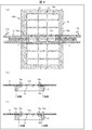
- FIG. 1A is a plan view showing the mask sheet frame bonding apparatus 10A in the present embodiment, in which the mask sheet 11 is fixed to the frame 12.
- FIG. 1B is a plan view showing a method of pulling the mask sheet 11.
- FIG. 1C is a cross-sectional view taken along line AA of FIG. 1A.
- the vapor deposition particles Z are vapor deposited on the TFT array layer 3 through the vapor deposition mask 19.
- the vapor deposition mask 19 is made of a mask sheet 11 welded to a frame 12 as a frame. Although only one mask sheet 11 is described for the frame 12 in FIG. 1A, the actual deposition mask 19 has a plurality of mask sheets 11 so as to cover all the openings 12 a of the frame 12. Lined up. Further, in (a) and (c) of FIG. 1, both ends of the mask sheet 11 are extended to the outside of the frame 12, but in the deposition mask 19, the portions extended to the outside of the frame 12 are It is cut and removed.
- the mask sheet 11 is formed of a strip-shaped metal sheet on which a plurality of mask patterns 11a corresponding to each RGB pixel are formed.
- the mask sheet 11 uses, for example, an invar material having a thickness of 10 ⁇ m to 50 ⁇ m as a base material.
- the plurality of mask patterns 11a formed at the central portion of the mask sheet 11 are disposed, and both ends of the mask sheet 11 are two grippable grip end portions 11b and 11b.
- the mask pattern 11a is shown in white, but in reality, many openings of 1 mm or less are formed to correspond to each pixel of RGB.
- One mask pattern 11 a is made of one corresponding to the size of, for example, a 5-inch panel.
- the mask sheet 11 is in the form of a sheet, a support for supporting the mask sheet 11 is required when the mask sheet 11 is used as a deposition mask 19 in a deposition step. Therefore, as shown in FIG. 1A, the mask sheet 11 is generally used in the form of a vapor deposition mask 19 in which the mask sheet 11 is joined to a frame 12 as a frame by welding. In the present embodiment, an auxiliary frame 13 is formed on the frame 12. When the frame 12 is large, it is preferable to provide the auxiliary frame 13 in this manner.
- the mask sheet frame bonding apparatus 10 A when manufacturing the deposition mask 19 by bonding the mask sheet 11 to the frame 12, the mask sheet frame bonding apparatus 10 A is used.
- the mask sheet frame body bonding apparatus 10A of the present embodiment holds the grip end portions 11b and 11b at both ends of the mask sheet 11 and applies a tensile force to the mask sheet 11.
- Grippers 14 are provided as tension jigs to be operated.
- the grippers 14, 14 sandwich the grip end portions 11b, 11b, for example, by a mechanism such as a selective shear.
- the mask sheet bonding apparatus 10A of the present embodiment is a pressing member for pressing at least one of the front surface and the back surface between the mask pattern 11a and the holding position of the gripper 14 in the mask sheet 11 on which the tensile force is applied.
- a roller 15 as a tubular member.
- the tubular member is not necessarily a rotating body such as the roller 15, but it is sufficient if it has a curved surface.
- the axial length of the roller 15 is equal to the width of the mask sheet 11.
- the axial length of the roller 15 may be larger than the width of the mask sheet 11 and at least larger than the width to be welded.
- the opposite side of the frame which is at least the surface of the mask sheet 11 is preferable.
- It can be either the front or back side.
- the frame 12 is brought into contact with the mask sheet 11 from the lower side of the mask sheet 11, and the roller 15 is pressed from the upper side to hold the mask sheet 11 between the frame 12 and the roller 15
- It is possible to adopt a method of The arrangement of the frame 12 may be on the upper side of the mask sheet 11.
- the pressing of the roller 15 to the mask sheet 11 can be either the front surface or the back surface of the mask sheet 11.
- one roller 15 can be used to press either the front surface or the back surface of the mask sheet 11.
- the grip end portions 11b and 11b at both ends of the mask sheet 11 are positioned below the roller 15, and the grippers 14 and 14 are used. It is preferable to apply a tensile force. Thereby, the pressing force of the roller 15 can be increased.
- the pressing target of the roller 15 can be both sides of the front surface and the back surface of the mask sheet 11. Thereby, since the mask sheet 11 can be pinched by two rollers 15 * 15, the blocking effect of the wrinkles C increases.
- the roller 15 can be suspended and supported by a wire or the like.
- the mask sheet 11 is pressed from both sides of the front surface and the back surface by two rollers 15 and 15, it is preferable to have an independent supporting mechanism. As a result, the two rollers 15 can be independently driven and pressed.
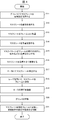
- FIG. 4 is a flowchart showing a method of bonding the mask sheet 11 to the frame 12.
- FIG. 5 is a plan view showing a configuration of a vapor deposition mask in which all mask sheets are welded to a frame.
- the main control of the flowchart shown in FIG. 4 is a control unit (not shown) of the mask sheet frame bonding apparatus 10A.
- the grips 11 and 11 at both ends of the mask sheet 11 are held by the grippers 14 and 14 (S11), and the mask sheet 11 is pulled with a weak force not to lose the holding. (S12). Here, this is called holding tension.
- the mask sheet 11 is disposed on the upper side of the frame 12 (S13).
- the mask sheet 11 is pulled with a force that does not bend (S14).
- this is called a preliminary support.
- a constant tensile force is applied.
- the mask pattern 11a of the mask sheet 11 is aligned so as to be accommodated in the opening 12a of the frame 12 (S15).
- the mask sheet 11 is stretched to a target force (S16). Since the tension at this time is performed while adjusting the position so that the mask pattern 11a is contained in the opening 12a of the frame 12, the tensile force is gradually increased to the target force and is not a constant tensile force.
- the roller 15 presses the surface of the mask sheet 11 so that the ridges C do not extend to the mask pattern 11a (S17).
- the mask sheet 11 placed on the frame 12 is pressed by the roller 15 from the upper surface thereof.
- the ridge C does not extend further inward than the pressing portion of the roller 15.
- the mask sheet 11 is welded to the frame 12 using a laser (S18).
- a laser for example, welding is performed while being held by the roller 15.
- the present invention is not necessarily limited to this, and welding may be performed after the pressure on the roller 15 is released.
- the laser is spot-irradiated at the contact portion of the frame 12 of the mask sheet 11, and the mask sheet 11 is melted. Can be spot welded to the frame 12 at the weld Y.
- the pressing position of the roller 15 against the mask sheet 11 has been described as the upper portion of the frame 12 in the mask sheet 11.
- the pressing position of the roller 15 with respect to the mask sheet 11 is not necessarily limited to this.
- the pressing position of the roller 15a can be inside the frame 12 and outside the mask pattern 11a.
- the rollers 15a and 15a as pressing members be provided on both the front and back surfaces of the mask sheet 11 so as to sandwich and hold the mask sheet 11.
- the mask sheet 11 on the frame 12 can be brought into close contact with the frame 12, so that welding Y can be easily performed.
- the rollers 15 b and 15 b can be disposed outside the frame 12 as a pressing position of the roller 15 b against the mask sheet 11.
- the rollers 15b and 15b may be only the front surface of the mask sheet 11, but it is preferable to provide the rollers 15b and 15b on both the front and back surfaces and to press the mask sheet 11 in a sandwiching manner.
- the mask sheet frame bonding apparatus 10A in the present embodiment bonds the mask sheet 11 having the mask pattern 11a to the frame 12 as a frame. Further, the mask sheet frame bonding apparatus 10A holds the grip end portions 11b and 11b of the mask sheet 11 and exerts a tensile force on the gripper sheets 14 and 14 as a tension jig to apply a tensile force to the mask sheet 11.
- a roller 15 other than the frame 12 is provided to press the opposite side of the frame, which is at least the surface between the mask pattern 11a and the holding position of the grippers 14 in the mask sheet.
- the wedge C stops at the pressing position of the roller 15 against the mask sheet 11.
- the portion of the mask sheet 11 where the mask pattern 11a is disposed there is no wrinkle C. Therefore, by bonding the mask sheet 11 to the frame 12 in a state in which the tensile force is applied uniformly without the wrinkles C, it becomes possible to perform the deposition operation using the high quality deposition mask 19. As a result, the occurrence of defective products can be reduced.
- a method of avoiding the occurrence of the wrinkles C in the part of the mask pattern 11a which is a necessary part is employed.
- the reduction of the wrinkles C can be realized by a simple member such as the roller 15 which presses the front side of the mask pattern 11 a in the mask sheet 11. For this reason, since adjustment of the tensile force of the grippers 14 is also unnecessary, it takes less time.
- the mask sheet frame bonding apparatus 10A capable of bonding the mask sheet 11 to the frame 12 without generating the wrinkles C by a simple method for the mask pattern 11a.
- the roller 15 is preferably made of a cylindrical member. Therefore, since the mask sheet 11 is pressed by the roller 15 which consists of a cylindrical member, the press surface is curving. As a result, since the mask sheet 11 is uniformly pressed without being scratched, uniform tension can be applied to the mask pattern 11a.
- the roller 15 holds the mask sheet 11 on both sides of the mask sheet 11 with respect to the bonding portion between the mask sheet 11 and the frame 12 It is possible to press 12.
- the mask sheet 11 can be pressed with the mask sheet 11 interposed between the frame 12 and the roller 15. Therefore, the frame 12 can be used as a pressing member. Further, since the mask sheet 11 can be welded to the frame 12 in a state where the adhesion strength of the frame 12 to the mask sheet 11 is increased, welding can be performed efficiently.
- the rollers 15 are provided on both the front surface and the back surface of the mask sheet 11, and are capable of sandwiching and pressing the mask sheet 11. As a result, on the pressing surface, it is possible to reliably block the wrinkles C extending inward from the holding position of the grippers 14.
- the roller 15a is located inside the frame 12. Thereby, the wrinkles C can be suppressed immediately before the mask pattern 11a.
- the roller 15a does not get in the way.
- the roller 15b can be located outside the frame 12. As a result, since the outside of the frame 12 is pressed, the pressing operation is easy. When the laser is irradiated from the upper side of the mask sheet 11 and the mask sheet 11 is joined to the frame 12 by welding, the roller 15b does not get in the way.
- the length of the rollers 15, 15a, 15a ', 15b in the direction orthogonal to the direction in which the tensile force is applied to the mask sheet 11 is the mask sheet.
- the weld length is greater than the weld length when welding 11 to the frame 12.
- the manufacturing method of the vapor deposition mask 19 in this Embodiment manufactures the vapor deposition mask 19 which joined the mask sheet
- the manufacturing method of the vapor deposition mask 19 which can bond the mask sheet 11 to the flame
- the length in the axial direction of the rollers 15, 15a and 15b is equal to the width of the mask sheet 11.
- the mask sheet frame bonding apparatus 10B of the present embodiment is different in that the roller 16 as a pressing member is composed of a plurality of divided rollers 16a.
- FIG. 8A shows a mask sheet frame bonding apparatus 10B in the present embodiment, and is a plan view showing a configuration of the roller 16 including a plurality of divided rollers 16a.
- FIG. 8B is a plan view showing a state in which two split rollers 16 a are used in accordance with the width of the mask sheet 11.
- FIG. 8C is a plan view showing a state in which three split rollers 16 a are used in accordance with the width of the mask sheet 11.
- each split roller 16a is movable on the shaft 16b.
- the length of each split roller 16a is, for example, the length L, and in the present embodiment, the lengths L are equal to each other.
- the lengths of the plurality of dividing rollers 16a may be different from one another. Further, in the present embodiment, the number of dividing rollers 16 a to be used is determined in accordance with the width of the mask sheet 11.
- a plurality of rollers 16 as pressing members are arranged in the mask sheet 11 in the direction orthogonal to the direction in which the tensile force is applied. . Then, the number of dividing rollers 16 a having a length corresponding to the width of the mask sheet 11 presses the mask sheet 11.
- the width of the mask sheet 11 may differ depending on the type of the OLED panel 1 as a display panel.
- the single-length roller 15 may be shorter than the width of the mask sheet 11.
- the roller 15 in preparation for such a case, from the beginning, the roller 15 is made up of a plurality of dividing rollers 16 a disposed in the mask sheet 11 in the direction orthogonal to the direction in which the tensile force is applied. There is. Then, at the time of use, the mask sheet 11 is pressed by using the number of dividing rollers 16 a that matches the width of the mask sheet 11. For example, the narrow mask sheet 11 is pressed by the two split rollers 16a, while the long mask sheet presses the mask sheet 11 by the three split rollers 16a.
- the mask sheet frame body bonding apparatus 10B which can have versatility can be provided.
- the length in the axial direction of the rollers 15, 15a and 15b is equal to the width of the mask sheet 11.
- the pressing member is composed of a plurality of split rollers 17a and split rollers 18a, and each split roller 17a or split roller 18a is coaxial or It differs in that it is provided on two axes.
- FIG. 9 shows a mask sheet frame bonding apparatus 10C in the present embodiment, and is a plan view showing the configuration of the dividing rollers 17a arranged on one axis when bonding the mask sheet 11 to the frame 12. It is.
- FIG. 10 shows a modification of the mask sheet frame bonding apparatus 10C according to the present embodiment, and in the case of bonding the mask sheet 11 to the frame 12, split rollers arranged in a zigzag on two axes. It is a top view which shows the structure of 18a * 18b and the dividing roller 18c.
- two dividing rollers 17a according to the present embodiment are provided on one axis, and the two dividing rollers 17a substantially match the width of the mask sheet 11. .
- the width of the mask sheet 11 can be satisfied by arranging the two division rollers 17a on the same axis. it can.
- the mask sheet 11 can be pressed with the same operation and effect as when pressed by, for example, the roller 15, which is a single pressing member that matches the width of the mask sheet 11.
- the method of arranging the division rollers is not necessarily on one axis on one side of the mask sheet 11.
- the split rollers 18a and 18b and the split rollers 18c as the plurality of pressing members are provided in a staggered manner on at least two axes.
- the split rollers 18a and 18b are provided on a single axis at intervals, and the split roller 18c is longer than the split rollers 18a and 18b in the length of the mask sheet 11 One is provided across the central line along the direction.
- the split rollers 18a, 18b, and 18c are arranged in a zigzag on two axes.
- the length of the dividing roller 18c is longer than the gap between the dividing rollers 18a and 18b.
- the dividing rollers 18a, 18b and 18c are arranged on the two axes, since the crucible C is blocked in at least two stages, the blocking effect of the crucible C is enhanced. On the other hand, since the number of pressing members can be reduced by arranging the split rollers 18a, 18b and 18c in a staggered manner on two axes, the wedge C can be blocked efficiently by a small number of pressing members.
- the plurality of rollers 18a, 18b, and 18c provided in a staggered manner on at least two axes are plural.
- the individual rollers 18a, 18b and 18c are arranged without a gap. Thus, it is possible to prevent the ridge C from extending to the mask pattern 11 a from the gap.
- the mask sheet and frame bonding apparatus 10A, 10B, and 10C is the mask sheet and frame bonding apparatus for bonding the mask sheet 11 having the mask pattern 11a to the frame (frame 12). And a pulling jig (gripper 14) for holding a tensile force on the mask sheet 11 by holding both end portions (grip end 11b) and the mask pattern 11a on the mask sheet 11 on which the tensile force acts.
- a pressing member rollerers 15, 15a, 15a ', 15b, 16 for pressing the opposite side of the frame, which is at least the surface between the holding position of the jig (gripper 14), and the other side of the frame (frame 12). And 16a, 17a, 18a, 18b, 18c).
- the mask sheet / frame bonding apparatus bonds the mask sheet provided with the mask pattern to the frame.
- tension is applied to the mask sheet with a tension jig.
- a pressure other than the frame pressing the opposite side of the frame which is at least the surface between the mask pattern and the holding position of the tension jig. And a member.
- the wrinkles stop at the pressing position of the pressing member against the mask sheet.
- no wrinkles are present on the portion of the mask sheet where the mask pattern is disposed. Therefore, by bonding the mask sheet to the frame in a state in which tensile force is applied uniformly without wrinkles, it becomes possible to perform work such as deposition using a high quality mask sheet, and generation of defective products Can be reduced.
- a method is employed in which the occurrence of wrinkles in a portion of the mask pattern, which is a necessary portion, is avoided instead of eliminating all occurrences of wrinkles in the mask sheet.
- the reduction of the occurrence of the wrinkles C can be realized by a simple member such as a pressing member which presses the front side of the mask pattern on the mask sheet. For this reason, the adjustment of the tensile force of the tensile jig is also unnecessary, so it takes less time.
- the pressing member (rollers 15, 15a, 15a ', 15b, 16, 16a, 17a, 18a, 18b, 18c) is a tubular member. It is preferable that it consists of.
- the pressing surface is curved.
- uniform tension can be applied to the mask pattern.
- the pressing member (roller 15) is closer to both ends of the mask sheet 11 than the bonded portion between the mask sheet 11 and the frame (frame 12).
- the frame (frame 12) is pressed with the mask sheet 11 interposed therebetween.
- the mask sheet can be pressed while sandwiching the mask sheet between the frame and the pressing member. Therefore, the frame can be used as a pressing member. In addition, since the mask sheet can be joined to the frame in a state in which the adhesion strength of the frame to the mask sheet is increased, the joining can be performed efficiently.
- the pressing member (rollers 15, 15a, 15a ', 15b, 16, 16a, 17a, 18a, 18b, 18c) is the mask sheet.
- the mask sheet 11 is provided on both the front surface and the back surface, and the mask sheet 11 is pressed.
- the pressing member sandwiches the mask sheet and presses from both the front and back surfaces of the mask sheet.
- wrinkles extending from the holding position of the pulling jig to the mask sheet can be reliably blocked.
- the pressing member (roller 15a) is located inside the frame (frame 12).
- the pressing member (roller 15b) is located outside the frame (frame 12).
- the pressing operation is easy. Further, for example, when the laser is irradiated from the upper side of the mask sheet and the mask sheet is joined to the frame by welding, the pressing member does not disturb.
- the length of the pressing member (rollers 15, 15a, 15a ', 15b) in the direction orthogonal to the direction in which the mask sheet 11 is subjected to the tensile force is preferably longer than the bonding length when bonding the mask sheet 11 to the frame (frame 12).
- the pressing members (16a, 17a, 18a, 18b and 18c) are orthogonal to the direction in which the tensile force is applied to the mask sheet 11.
- a plurality of pressing members (16a, 17a, 18a, 18b, 18c) having a length corresponding to the width of the mask sheet 11 are arranged so that a plurality of them are arranged in the direction to press the mask sheet 11. Is preferred.
- the width of the mask sheet may be different.
- a single length pressing member may be shorter than the width of the mask sheet.
- a plurality of pressing members are initially disposed in the mask sheet in the direction orthogonal to the direction in which the tensile force is applied, as the pressing member.
- a mask sheet is pressed using the press member of the number matched with the width
- the mask sheet frame joining device which can have versatility can be provided.
- the plurality of pressing members (16a / 17a) are provided on the same axis.
- the width of the mask sheet can be satisfied by arranging the plurality of pressing members on the same axis.
- the mask sheet can be pressed with the same effect as when pressed by a single pressing member that matches the width of the mask sheet.
- the plurality of pressing members (18a, 18b, 18c) are provided in a staggered manner on at least two axes.
- the crucible is blocked in at least two stages, so that the barrier effect of the crucible is enhanced.
- the number of pressing members can be reduced by arranging the pressing members in a staggered manner on two axes, wrinkles can be efficiently blocked by a small number of pressing members.
- the plurality of pressing members (rollers 18a, 18b, 18c) provided in a staggered manner on the at least two axes are viewed from both ends of the mask sheet 11.
- the plurality of pressing members are disposed without a gap therebetween.
- the method for producing a vapor deposition mask according to aspect 12 of the present invention is a method for producing a vapor deposition mask for producing a vapor deposition mask 19 in which the mask sheet 11 is bonded to a frame using the mask sheet / frame bonding apparatus described above. And a pulling step of holding the mask sheet 11 at both ends to apply a pulling force to the mask sheet 11, and the mask sheet 11 being accommodated in the opening 12 a of the frame (frame 12) 12) contacting the mask sheet 11; pressing the mask sheet 11 with the pressing members (rollers 15, 15a, 15a ', 15b); and pressing the mask sheet 11 into the frame.
- Bonding step of bonding to the body (frame 12) and the pressing member (rollers 15, 15a, 15a ', 15b) after bonding is completed A pressure releasing step for releasing the pressure on the mask sheet 11, a tension releasing step for releasing the tension on the mask sheet 11, and a cutting step for manufacturing the vapor deposition mask 19 by cutting the end of the mask sheet 11. And in this order.
Landscapes
- Engineering & Computer Science (AREA)
- Optics & Photonics (AREA)
- Physics & Mathematics (AREA)
- Mechanical Engineering (AREA)
- Chemical & Material Sciences (AREA)
- Manufacturing & Machinery (AREA)
- Plasma & Fusion (AREA)
- Materials Engineering (AREA)
- Organic Chemistry (AREA)
- Metallurgy (AREA)
- Chemical Kinetics & Catalysis (AREA)
- Microelectronics & Electronic Packaging (AREA)
- Electroluminescent Light Sources (AREA)
Abstract
マスクパターンに対して簡便な方法により皺を発生させずに、マスクシートを枠体に接合し得るマスクシート枠体接合装置及び蒸着マスクの製造方法を提供する。マスクシート枠体接合装置(10A)は、マスクパターン(11a)を配したマスクシート(11)をフレーム(12)に接合する。マスクシート(11)のグリップ用端部(11b・11b)を保持してマスクシート(11)に引張り力を作用させるグリッパ(14・14)と、引張り力が作用したマスクシート(11)における、マスクパターン(11a)とグリッパ(14)の保持位置との間における少なくとも表面である、フレーム(12)の反対側を押圧する、フレーム(12)以外の押圧部材であるローラ(15)を備えている。
Description
本発明は、マスクパターンを配したマスクシートを枠体に接合するマスクシート枠体接合装置及び蒸着マスクの製造方法に関するものである。
有機エレクトロルミネッセンス(以下、「有機EL」という。)ディスプレイは、基板に発光体となる有機発光ダイオードをマトリクス状に多数配設して構成されたディスプレイである。
有機発光ダイオードは、色の三原色であるRGBをそれぞれ発光する3種類の素子からなっており、各素子は、例えば、各RGBのための有機系の発光材料を基板に蒸着して形成される。発光材料は、RGB毎にパターン状に成膜する必要があり、そのためには、所望のパターン位置を開口し、かつそれ以外を覆うメタルマスクが必要となる。
メタルマスクは、例えば板厚30μm以下の金属の薄板に、パターンとする部分をエッチング工程で金属除去する加工を施したものである。エッチングされた金属薄板はシート状に裁断され、メタルマスクシートとなる。メタルマスクシートは、工程に応じて、例えば固定枠へ取り付けられて工程に投入される。メタルマスクシートを固定枠へ取り付け固定するときには、メタルマスクシートにキズ、シワ、凹みを発生しないようにするため、及び加工の寸法精度を低下させないために、常に張力をかけておくことが求められている。
しかしながら、メタルマスクシートを固定枠に取り付ける作業は人が行うことが多く、張力の掛け方がわずかに均等でなくなることにより、シワが発生して、製品が不良となることが多かった。
そこで、特許文献1に開示されたメタルマスクシートの搬送装置では、メタルマスクシートの表面を吸着手段にて吸着しながら該メタルマスクシートに張力を掛ける架張手段を備えると共に、メタルマスクシート上に設けたアライメントマークを読取る撮像手段を備えている。これにより、メタルマスクシートを吸着する直前及び直後に撮像手段にて読取ったアライメントマークの位置のズレ量を求めて、架張手段により幅方向の張力を調整して補正するようになっている。
しかしながら、上記従来の特許文献1に開示されたメタルマスクシートの搬送装置では、シワがなくなるように補正するためには、架張手段による張力の微調整が必要になる。このため、架張手段に加えて、メタルマスクシートに対して均等に精度良く調整して張力を付与する架張手段が必要となるので、高価であると共に、調整に時間を要するという問題を有している。
本発明は、前記従来の問題点に鑑みなされたものであって、その目的は、マスクパターンに対して簡便な方法により皺を発生させずに、マスクシートを枠体に接合し得るマスクシート枠体接合装置及び蒸着マスクの製造方法を提供することにある。
本発明の一態様におけるマスクシート枠体接合装置は、前記の課題を解決するために、マスクパターンを配したマスクシートを枠体に接合するマスクシート枠体接合装置において、前記マスクシートの両端部を保持して該マスクシートに引張り力を作用させる引張り治具と、前記引張り力が作用したマスクシートにおける、前記マスクパターンと引張り治具の保持位置との間における少なくとも表面である、枠体の反対側を押圧する枠体以外の押圧部材とを備えていることを特徴としている。
本発明の一態様における蒸着マスクの製造方法は、前記の課題を解決するために、前記記載のマスクシート枠体接合装置を用いてマスクシートを枠体に接合した蒸着マスクを製造する蒸着マスクの製造方法であって、前記マスクシートを両端で保持して該マスクシートに引張り力を付与する引張りステップと、前記マスクパターンが前記枠体の開口内に収まるようにして、該枠体を前記マスクシートに接触させる接触ステップと、押圧部材にて、前記マスクシートの表面を押圧する押圧ステップと、前記マスクシートを前記枠体に接合する接合ステップと、接合完了後に、前記押圧部材のマスクシートへの押圧を解除する押圧解除ステップと、前記マスクシートへの引張り力を解除する引張り力解除ステップと、前記マスクシートの端部を切断して蒸着マスクを製造する切断ステップとをこの順に含んでいることを特徴としている。
本発明の一態様によれば、マスクパターンに対して簡便な方法により皺を発生させずに、マスクシートを枠体に接合し得るマスクシート枠体接合装置及び蒸着マスクの製造方法を提供するという効果を奏する。
〔実施の形態1〕
本発明の一実施形態について図1~図7に基づいて説明すれば、以下のとおりである。
本発明の一実施形態について図1~図7に基づいて説明すれば、以下のとおりである。
(OLEDパネルの製造方法の概要)
本実施の形態のマスクシート枠体接合装置を備えた表示パネルとしてのOLED(Organic Light Emitting Diode)パネル1の製造方法について、図2の(a)(b)及び図3に基づいて説明する。図2の(a)は、OLEDパネル1の構成を示す断面図である。図2の(b)は、OLEDパネル1の製造方法を示すフローチャートである。図3は、OLEDパネル1の蒸着工程を示す模式断面図である。
本実施の形態のマスクシート枠体接合装置を備えた表示パネルとしてのOLED(Organic Light Emitting Diode)パネル1の製造方法について、図2の(a)(b)及び図3に基づいて説明する。図2の(a)は、OLEDパネル1の構成を示す断面図である。図2の(b)は、OLEDパネル1の製造方法を示すフローチャートである。図3は、OLEDパネル1の蒸着工程を示す模式断面図である。
OLEDパネル1は、発光体が有機エレクトロルミネッセンス(以下、「有機EL」という。)からなっているパネルであり、図2の(a)に示すように、基板2とTFTアレイ層3とOLED素子層4と保護ガラス5とが順に積層されている。TFTアレイ層3は、薄膜トランジスタ及び信号線等を含んでいる。OLED素子層4は、色の三原色であるRGBをそれぞれ発光する3種類の素子を平面的にマトリクス状に配設した層である。各素子は、例えば、各RGBのための有機系の発光材料を基板に蒸着して形成される。OLED素子層4は、また、電気的機能層及び陰極を含んでいる。保護ガラス5は、OLED素子層4の各RGBの素子を封止するものである。
OLEDパネル1を製造する場合には、図2の(b)に示すように、まず、基板2にTFTアレイ層3を形成する(S1)。次いで、蒸着マスクを用いて、TFTアレイ層3の上にOLED素子層4を形成する(S2)。この工程を、OLED素子層形成工程と称し、このOLED素子層形成工程は蒸着工程を含んでいる。
蒸着工程では、図3に示すように、基板2の表面に形成したTFTアレイ層3の表面に、複数の貫通孔を有するマスクシート11を密着させ、真空下において、蒸着源20で気化又は昇華させた有機発光材である蒸着粒子Zを蒸着マスク19越しにTFTアレイ層3に蒸着させる。これにより、蒸着マスク19の貫通孔に対応するパターンにて蒸着パターンを形成する。
その後、図2の(b)に示すように、OLED素子層4を保護ガラス5で封止し(S3)、分断つまり個片化を行い(S4)、OLEDパネル1とする(S5)。このS5では、OLEDパネル1に駆動ドライバや偏光板及びタッチパネル等の実装を行う。
(マスクシート枠体接合装置)
OLEDパネル1の製造における蒸着工程においては、本実施の形態では、蒸着マスク19を作製するためにマスクシート枠体接合装置10Aが使用される。
OLEDパネル1の製造における蒸着工程においては、本実施の形態では、蒸着マスク19を作製するためにマスクシート枠体接合装置10Aが使用される。
本実施の形態のマスクシート枠体接合装置10Aの構成について、図1の(a)(b)(c)に基づいて説明する。図1の(a)は、本実施の形態におけるマスクシート枠体接合装置10Aを示すものであって、マスクシート11をフレーム12に固定する状態を示す平面図である。図1の(b)は、マスクシート11の引張り方法を示す平面図である。図1の(c)は、図1の(a)のA-A線矢視断面図である。
前述したように、蒸着工程においては、蒸着粒子Zが蒸着マスク19を介してTFTアレイ層3に蒸着される。蒸着マスク19は、図1の(a)(c)に示すように、マスクシート11が枠体としてのフレーム12に溶接されたものからなっている。尚、図1の(a)では、フレーム12に対して一個のマスクシート11しか記載していないが、実際の蒸着マスク19は、フレーム12の開口12aを全て塞ぐように複数のマスクシート11が並んでいる。また、図1の(a)(c)では、マスクシート11の両端部が、フレーム12の外側に延設されているが、蒸着マスク19では、フレーム12の外側に延設される部分は、切断して除去される。
マスクシート11は、図1の(b)に示すように、短冊状に形成されたメタルシートに各RGB画素に対応する複数個のマスクパターン11aが形成されたものからなっている。マスクシート11は、母材として、例えば、厚さ10μm~50μmのインバー材等が用いられている。
マスクシート11の中央部には、前記複数個形成されたマスクパターン11aが配されていると共に、マスクシート11の両端部は、グリップ可能な2つのグリップ用端部11b・11bとなっている。尚、図1の(b)においては、マスクパターン11aを白抜き状にて記載しているが、実際には、RGB各画素に対応すべく、1mm以下の開口が多数形成されている。一個のマスクパターン11aは、例えば5インチパネル等の大きさに対応したものからなっている。
前記マスクシート11は、シート状になっているので、蒸着マスク19として蒸着工程で使用する場合には、マスクシート11を支持する支持体が必要となる。そこで、マスクシート11は、一般的に、図1の(a)に示すように、枠体としてのフレーム12にマスクシート11を溶接により接合した蒸着マスク19の形態で使用される。本実施の形態では、フレーム12には、補助フレーム13が形成されている。フレーム12が大きい場合には、このように、補助フレーム13を設ける方が好ましい。
本実施の形態では、マスクシート11をフレーム12に接合して蒸着マスク19を製造するときには、マスクシート枠体接合装置10Aが用いられる。
本実施の形態のマスクシート枠体接合装置10Aは、図1の(b)に示すように、マスクシート11の両端部のグリップ用端部11b・11bを保持してマスクシート11に引張り力を作用させる引張り治具としてのグリッパ14・14を備えている。グリッパ14・14は、例えば選択ばさみ等の機構により、グリップ用端部11b・11bを挟む。
また、本実施の形態のマスクシート枠体接合装置10Aは、引張り力が作用したマスクシート11における、マスクパターン11aとグリッパ14の保持位置との間における表面及び裏面の少なくとも一方を押圧する押圧部材及び筒状部材としてローラ15とを備えている。本発明の一態様においては、筒状部材は必ずしもローラ15のような回転体でなく、湾曲面を有していれば足りる。
また、本実施の形態では、ローラ15の軸方向の長さは、マスクシート11の幅と同じ長さとなっている。ただし、必ずしもこれに限らず、ローラ15の軸方向の長さは、マスクシート11の幅よりも大きくてもよく、少なくとも溶接する幅よりも大きい。
ローラ15の押圧対象については、マスクシート11の少なくとも表面である、枠体の反対側が好ましい。0御まし医表面及び裏面のいずれか一方とすることができる。この場合、例えば、フレーム12をマスクシート11の下側から該マスクシート11に当接させ、ローラ15をその上側から押圧することによりフレーム12とローラ15とによって、マスクシート11を挟持して押圧する方法を採用することが可能である。尚、フレーム12の配置は、マスクシート11の上側であってもよい。このことを考慮する場合には、ローラ15のマスクシート11への押圧は、マスクシート11の表面及び裏面のいずれか一方とすることができる。
このような方法においては、後に詳述するように、グリッパ14・14にてグリップ用端部11b・11bを保持したときに発生する皺Cがマスクパターン11aにまで延びること押圧位置にて遮断すると共に、マスクシート11をフレーム12に密着させて溶接Yを容易にするという効果がある。
或いは、フレーム12以外の位置において、1つのローラ15を用いてマスクシート11の表面及び裏面のいずれか一方を押圧することができる。この場合、例えば、マスクシート11の裏面のみを押圧するときには、マスクシート11の両端部のグリップ用端部11b・11bをローラ15よりも下側位置となるようにして、グリッパ14・14にて引張り力を作用させることが好ましい。これにより、ローラ15の押圧力を増大させることができる。
また、ローラ15の押圧対象について、マスクシート11の表面及び裏面の両側とすることができる。これにより、2つのローラ15・15でマスクシート11を挟持することができるので、皺Cの遮断効果が高まる。
ここで、ローラ15の支持方法について、例えば、ローラ15をマスクシート11の下側から押圧する場合には、ローラ15をワイヤ等で吊り下げて支持することが可能である。一方、2つのローラ15・15にてマスクシート11を表面及び裏面の両側から押圧する場合には、それぞれ独立した支持機構を有していることが好ましい。これにより、2つのローラ15・15をそれぞれ独立駆動させて押圧することが可能となる。
前記構成のマスクシート枠体接合装置10Aにおけるマスクシート11のフレーム12への接合方法について、図4に基づいて説明する。図4はマスクシート11のフレーム12への接合方法を示すフローチャートである。図5は、全てのマスクシートをフレームに溶接した蒸着マスクの構成を示す平面図である。尚、図4に示すフローチャートの制御主体は、マスクシート枠体接合装置10Aの図示しない制御部である。
図4に示すように、まず、グリッパ14・14にて、マスクシート11の両端のグリップ用端部11b・11bを保持し(S11)、マスクシート11を保持が外れない程度の弱い力で引張る(S12)。ここでは、これを保持架張という。次いで、マスクシート11をフレーム12の上側に配置する(S13)。このとき、マスクシート11が撓まない程度の力で引張る(S14)。ここでは、これを予備架張という。予備架張では一定の引張り力を作用させる。この状態で、マスクシート11のマスクパターン11aがフレーム12の開口12a内に収まるように位置合わせする(S15)。このとき、マスクシート11を目標力まで架張する(S16)。尚、このときの架張は、マスクパターン11aがフレーム12の開口12a内に収まるように位置調整しながら行うので、引張り力は徐々に目標力まで増加され、一定の引張り力ではない。
この作業を行っている場合、通常、図1の(b)に示すように、マスクシート11における、グリッパ14・14での保持部分とマスクパターン11aとの間に皺Cが発生する。そこで、この皺Cがマスクパターン11aにまで及ばないように、本実施の形態では、ローラ15にて、マスクシート11の表面を押圧する(S17)。具体的には、図1の(c)に示すように、フレーム12に載置されたマスクシート11をその上面からローラ15にて押圧する。これにより、皺Cは、ローラ15の押圧部部分よりも内部に延びることがなくなる。
次いで、この状態で、マスクシート11をフレーム12にレーザを用いて溶接する(S18)。このとき、例えば、ローラ15で押さえながら溶接する。ただし、必ずしもこれに限らず、ローラ15の押圧を解除してから溶接してもよい。
溶接に際しては、図1の(a)(c)に示すように、例えば、マスクシート11のフレーム12の接触部分においてレーザをスポット照射する、これにより、マスクシート11が溶融するので、マスクシート11をフレーム12に溶接部Yにてスポット溶接することができる。
溶接が完了すれば、ローラ15の押圧を解除し(S19)、グリップ用端部11b・11bのグリッパ14・14を解除する(S20)。このとき、マスクパターン11aに皺Cが無い状態でマスクシート11がフレーム12に旨く溶接できているかの品質検査が行われる。
次いで、同様にして、複数のマスクシート11をフレーム12に溶接する。全ての溶接が完了すると、マスクシート11における溶接Yの外側部分つまり端部を切断する(S21)。
これにより、図5に示すように、フレーム12に固定されたマスクシート11、つまり蒸着マスク19が完成する。
尚、前述した説明では、マスクシート11に対するローラ15の押圧位置を、マスクシート11におけるフレーム12の上側部分として説明した。しかし、マスクシート11に対するローラ15の押圧位置は、必ずしもこれに限らない。例えば、図6の(a)(b)に示すように、ローラ15aの押圧位置を、フレーム12の内部であって、かつマスクパターン11aよりも外側とすることが可能である。この場合、押圧部材としてのローラ15a・15aは、マスクシート11の表面及び裏面の両方に設けて、マスクシート11を挟むようにして押圧することが好ましい。また、この場合、例えば、図6の(c)に示すように、フレーム12上のマスクシート11の表面をローラ15a’で押圧することが好ましい。これにより、フレーム12上のマスクシート11を該フレーム12に密着させることができるので、溶接Yを容易に行うことができる。
また、マスクシート11に対するローラ15bの押圧位置として、図7の(a)(b)に示すように、フレーム12の外側にローラ15b・15bを配することが可能である。この場合も、ローラ15b・15bは、マスクシート11の表面だけであってもよいが、表面及び裏面の両方に設けて、マスクシート11を挟むようにして押圧することが好ましい。
このように、本実施の形態におけるマスクシート枠体接合装置10Aは、マスクパターン11aを配したマスクシート11を枠体としてのフレーム12に接合する。また、マスクシート枠体接合装置10Aは、マスクシート11のグリップ用端部11b・11bを保持してマスクシート11に引張り力を作用させる引張り治具としてのグリッパ14・14と、引張り力が作用したマスクシートにおける、マスクパターン11aとグリッパ14・14の保持位置との間における少なくとも表面である、枠体の反対側を押圧する、フレーム12以外のローラ15とを備えている。
これにより、ローラ15のマスクシート11への押圧位置で皺Cが止まる。この結果、マスクシート11におけるマスクパターン11aが配された部分には、皺Cが無い状態となっている。したがって、皺Cが無く、均一に引張り力を作用させた状態でマスクシート11をフレーム12に接合することにより、質の高い蒸着マスク19を用いで蒸着作業を行うことが可能となる。その結果、不良品の発生の低減を図ることができる。
また、本実施の形態においては、マスクシート11における皺Cの発生を全て無くすのではなく、必要部分であるマスクパターン11aの部分に皺Cが発生するのを回避する方法を採用している。具体的には、マスクシート11におけるマスクパターン11aの手前を押圧するローラ15という簡単な部材にて皺Cの低減を実現できるようになっている。このため、グリッパ14・14の引張り力の調整も不要であるので、時間も掛からない。
したがって、マスクパターン11aに対して簡便な方法により皺Cを発生させずに、マスクシート11をフレーム12に接合し得るマスクシート枠体接合装置10Aを提供することができる。
また、本実施の形態におけるマスクシート枠体接合装置10Aでは、ローラ15は、筒状部材からなっていることが好ましい。これにより、筒状部材からなるローラ15にてマスクシート11を押圧するので、押圧面が湾曲している。この結果、マスクシート11に傷を付けずに均等に押圧するので、マスクパターン11aに対して均等な張力を付与することができる。
また、本実施の形態におけるマスクシート枠体接合装置10Aでは、ローラ15は、マスクシート11とフレーム12との接合部分よりも該マスクシート11の両端部側にて、マスクシート11を挟んでフレーム12を押圧することが可能である。
これにより、フレーム12とローラ15との間にマスクシート11を挟んでマスクシート11を押圧することができる。このため、フレーム12を押圧部材として利用することができる。また、マスクシート11に対するフレーム12の密着強度を大きくした状態で、マスクシート11をフレーム12に溶接することができるので、溶接を効率よく行うことができる。
また、本実施の形態におけるマスクシート枠体接合装置10Aでは、ローラ15は、マスクシート11における表面及び裏面の両方に設けられ、マスクシート11を挟んで押圧することが可能である。この結果、押圧面では、グリッパ14・14の保持位置から内部に向かって延びてきた皺Cを確実に遮断させることができる。
また、本実施の形態におけるマスクシート枠体接合装置10Aでは、ローラ15aは、フレーム12の内側に位置しているとするとことができる。これにより、マスクパターン11aの直前で皺Cを抑制することができる。また、マスクシート11の上側からレーザを照射してマスクシート11をフレーム12に溶接にて接合する場合に、ローラ15aが邪魔にならない。
また、本実施の形態におけるマスクシート枠体接合装置10Aでは、ローラ15bは、フレーム12の外側に位置しているとすることができる。これにより、フレーム12の外側を押圧するので押圧作業が容易である。また、マスクシート11の上側からレーザを照射してマスクシート11をフレーム12に溶接にて接合する場合に、ローラ15bが邪魔にならない。
また、本実施の形態におけるマスクシート枠体接合装置10Aでは、ローラ15・15a・15a’・15bにおける、マスクシート11に対して引張り力を作用させる方向に直交する方向の長さは、マスクシート11をフレーム12に溶接するときの溶接長さよりも長いことが好ましい。これにより、溶接長さよりも外側から皺Cが延びてマスクパターン11aに悪影響を与えるのを防止することができる。
また、本実施の形態における蒸着マスク19の製造方法は、本実施の形態のマスクシート枠体接合装置10Aを用いてマスクシート11をフレーム12に接合した蒸着マスク19を製造する。そして、蒸着マスク19の製造方法は、マスクシート11を両端で保持してマスクシート11に引張り力を付与する引張りステップと、マスクシート11がフレーム12の開口12a内に収まるようにして、フレーム12をマスクシート11に接触させる接触ステップと、ローラ15・15a・15a’・15bにて、マスクシート11の表面を押圧する押圧ステップと、マスクシート11をフレーム12に接合する接合ステップと、接合完了後に、ローラ15・15a・15a’・15bのマスクシート11への押圧を解除する押圧解除ステップと、マスクシート11への引張り力を解除する引張り力解除ステップと、マスクシート11の端部を切断して蒸着マスク19を製造する切断ステップとをこの順に含んでいる。
これにより、蒸着マスク19を製造する際に、マスクパターン11aに対して簡便な方法により皺Cを発生させずに、マスクシート11をフレーム12に接合し得る蒸着マスク19の製造方法を提供することができる。
〔実施の形態2〕
本発明の他の実施の形態について図8に基づいて説明すれば、以下のとおりである。尚、本実施の形態において説明すること以外の構成は、前記実施の形態1と同じである。また、説明の便宜上、前記の実施の形態1の図面に示した部材と同一の機能を有する部材については、同一の符号を付し、その説明を省略する。
本発明の他の実施の形態について図8に基づいて説明すれば、以下のとおりである。尚、本実施の形態において説明すること以外の構成は、前記実施の形態1と同じである。また、説明の便宜上、前記の実施の形態1の図面に示した部材と同一の機能を有する部材については、同一の符号を付し、その説明を省略する。
前記実施の形態1のマスクシート枠体接合装置10Aでは、ローラ15・15a・15bの軸方向の長さがマスクシート11の幅に一致するようになっていた。これに比べて、本実施の形態のマスクシート枠体接合装置10Bは、押圧部材としてのローラ16は、複数の分割ローラ16aからなっている点が異なっている。
本実施の形態のマスクシート枠体接合装置10Bにおけるローラ16の構成について、図8の(a)(b)(c)に基づいて説明する。図8の(a)は、本実施の形態におけるマスクシート枠体接合装置10Bを示すものであって、複数の分割ローラ16aからなるローラ16の構成を示す平面図である。図8の(b)は、マスクシート11の幅に合わせて分割ローラ16aを2個使用する状態を示す平面図である。図8の(c)は、マスクシート11の幅に合わせて分割ローラ16aを3個使用する状態を示す平面図である。
本実施の形態のローラ16は、シャフト16bに分割ローラ16aが例えば4個設けられている。シャフト16bは4個の分割ローラ16aの長さよりも長く、かつ各分割ローラ16aはシャフト16b上で移動可能になっている。各分割ローラ16aの長さは、例えば、長さLとなっており、本実施の形態では、互いに等しい長さLとなっている。ただし、本発明の一態様においては、複数の分割ローラ16aの長さは、互いに異なっていてもよい。そして、本実施の形態では、マスクシート11の幅に合わせて、使用される分割ローラ16aの個数が決定されるようになっている。
例えば、図8の(b)に示すように、マスクシート11の幅が2Lの場合には、2個の分割ローラ16aが押圧に使用される。また、例えば、図7の(c)に示すように、マスクシート11の幅が3Lの場合には、3個の分割ローラ16aが押圧に使用される。尚、図8の(a)(b)において、使用しない分割ローラ16aは、シャフト16bに沿って側方に移動される。
このように、本実施の形態におけるマスクシート枠体接合装置10Bでは、押圧部材としてのローラ16は、マスクシート11における、引張り力を作用させる方向に対して直交する方向に複数個配置されている。そして、マスクシート11の幅に応じた長さとなる個数の分割ローラ16aがマスクシート11を押圧するようになっている。
例えば、表示パネルとしてのOLEDパネル1の種類によっては、マスクシート11の幅が異なる場合がある。その場合に、実施の形態1のように、単一の長さのローラ15では、マスクシート11の幅よりも短い場合がある。本実施の形態においては、そのような場合に備えて、最初から、ローラ15はマスクシート11における、引張り力を作用させる方向に対して直交する方向に複数個配置された分割ローラ16aからなっている。そして、使用に際しては、マスクシート11の幅に合致する個数の分割ローラ16aを用いてマスクシート11を押圧する。例えば、幅の狭いマスクシート11は、2個の分割ローラ16aで押圧する一方、幅の長いマスクシートは、3個の分割ローラ16aでマスクシート11を押圧する。
これにより、汎用性をもたすことができるマスクシート枠体接合装置10Bを提供することができる。
〔実施の形態3〕
本発明のさらに他の実施の形態について図9及び図10に基づいて説明すれば、以下のとおりである。尚、本実施の形態において説明すること以外の構成は、前記実施の形態1及び実施の形態2と同じである。また、説明の便宜上、前記の実施の形態1及び実施の形態2の図面に示した部材と同一の機能を有する部材については、同一の符号を付し、その説明を省略する。
本発明のさらに他の実施の形態について図9及び図10に基づいて説明すれば、以下のとおりである。尚、本実施の形態において説明すること以外の構成は、前記実施の形態1及び実施の形態2と同じである。また、説明の便宜上、前記の実施の形態1及び実施の形態2の図面に示した部材と同一の機能を有する部材については、同一の符号を付し、その説明を省略する。
前記実施の形態1のマスクシート枠体接合装置10Aでは、ローラ15・15a・15bの軸方向の長さがマスクシート11の幅に一致するようになっていた。これに比べて、本実施の形態のマスクシート枠体接合装置10Cは、押圧部材は、複数の分割ローラ17a及び分割ローラ18aからなっていると共に、各分割ローラ17a又は分割ローラ18aが同軸上又は2軸上に設けられている点が異なっている。
本実施の形態のマスクシート枠体接合装置10Cにおける押圧部材としての複数の分割ローラ17aの構成について、図8及び図9に基づいて説明する。図9は、本実施の形態におけるマスクシート枠体接合装置10Cを示すものであって、マスクシート11をフレーム12に接合する場合に、一軸上に配された分割ローラ17aの構成を示す平面図である。図10は、本実施の形態におけるマスクシート枠体接合装置10Cの変形例を示すものであって、マスクシート11をフレーム12に接合する場合に、二軸上に千鳥状に配された分割ローラ18a・18b及び分割ローラ18cの構成を示す平面図である。
本実施の形態の分割ローラ17aは、図9に示すように、一軸上に例えば2個設けられており、2個の分割ローラ17aによって、略マスクシート11の幅に一致するようになっている。
これにより、単一の分割ローラ17aではマスクシート11の幅に満たない場合であっても、例えば2個の分割ローラ17aを同一軸上に配することによりマスクシート11の幅を充足させることができる。この結果、マスクシート11の幅に対して、マスクシート11の幅に合致する単一の押圧部材である例えばローラ15で押圧した場合と同じ作用効果でマスクシート11を押圧することができる。
また、本実施の形態のマスクシート枠体接合装置10Cにおいては、分割ローラの配置の方法は、マスクシート11の片側において必ずしも一軸上とは限らない。
例えば、図10に示すように、複数個の押圧部材として分割ローラ18a・18b及び分割ローラ18cは、少なくとも二軸上に千鳥状に設けられているとすることが可能である。
すなわち、図9に示すように、例えば、分割ローラ18a・18bは、一軸上に間隔をあけて設けられていると共に、分割ローラ18cは、分割ローラ18a・18bよりも外側においてマスクシート11の長手方向に沿う中心線上を跨いで1個設けられている。この結果、分割ローラ18a・18b・18cは二軸上に千鳥状に配されていることになる。尚、分割ローラ18cの長さは、分割ローラ18a・18bの隙間よりも長くなっている。
このように、二軸上に分割ローラ18a・18b・18cを配することによって、少なくとも二段で皺Cを遮断することになるので、皺Cの遮断効果が高まる。一方、二軸上に千鳥状に分割ローラ18a・18b・18cを配することによって、押圧部材の個数を減らせるので、少ない個数の押圧部材で効率よく皺Cを遮断することができる。
また、本実施の形態におけるマスクシート枠体接合装置10Cでは、少なくとも二軸上に千鳥状に設けられた複数個のローラ18a・18b・18cをマスクシート11の両端側から見たときに、複数個のローラ18a・18b・18cは、互いに隙間なく配されている。これにより、隙間から皺Cがマスクパターン11aに延びるのを防止することができる。
〔まとめ〕
本発明の態様1におけるマスクシート枠体接合装置10A・10B・10Cは、マスクパターン11aを配したマスクシート11を枠体(フレーム12)に接合するマスクシート枠体接合装置において、前記マスクシート11の両端部(グリップ用端部11b)を保持して該マスクシート11に引張り力を作用させる引張り治具(グリッパ14)と、前記引張り力が作用したマスクシート11における、前記マスクパターン11aと引張り治具(グリッパ14)の保持位置との間における少なくとも表面である、枠体の反対側を押圧する、前記枠体(フレーム12)以外の押圧部材(ローラ15・15a・15a’・15b・16・16a・17a・18a・18b・18c)とを備えていることを特徴としている。
本発明の態様1におけるマスクシート枠体接合装置10A・10B・10Cは、マスクパターン11aを配したマスクシート11を枠体(フレーム12)に接合するマスクシート枠体接合装置において、前記マスクシート11の両端部(グリップ用端部11b)を保持して該マスクシート11に引張り力を作用させる引張り治具(グリッパ14)と、前記引張り力が作用したマスクシート11における、前記マスクパターン11aと引張り治具(グリッパ14)の保持位置との間における少なくとも表面である、枠体の反対側を押圧する、前記枠体(フレーム12)以外の押圧部材(ローラ15・15a・15a’・15b・16・16a・17a・18a・18b・18c)とを備えていることを特徴としている。
前記構成によれば、マスクシート枠体接合装置は、マスクパターンを配したマスクシートを枠体に接合する。その際、皺を発生させない状態でマスクシートを枠体に接合するために、引張り治具にてマスクシートに張力を掛けておく。しかし、マスクシートに均等に張力を掛けることは難しく、通常、引張り治具のマスクシートの保持位置からマスクシートの中央に配されたマスクパターンに向かって皺が発生する。
そこで、本発明の一態様においては、引張り力が作用したマスクシートにおける、マスクパターンと引張り治具の保持位置との間における少なくとも表面である、枠体の反対側を押圧する枠体以外の押圧部材とを備えている。
これにより、押圧部材のマスクシートへの押圧位置で皺が止まる。この結果、マスクシートにおけるマスクパターンが配された部分には、皺が無い状態となっている。したがって、皺が無く、均一に引張り力を作用させた状態でマスクシートを枠体に接合することにより、質の高いマスクシートを用いで蒸着等の作業を行うことが可能となり、不良品の発生の低減を図ることができる。
また、本発明の一態様においては、マスクシートにおける皺の発生を全て無くすのではなく、必要部分であるマスクパターンの部分に皺が発生するのを回避する方法を採用している。具体的には、マスクシートにおけるマスクパターンの手前を押圧する押圧部材という簡単な部材にて皺Cの発生の低減を実現できるようになっている。このため、引張り治具の引張り力の調整も不要であるので、時間も掛からない。
したがって、マスクパターンに対して簡便な方法により皺を発生させずに、マスクシートを枠体に接合し得るマスクシート枠体接合装置を提供することができる。
本発明の態様2におけるマスクシート枠体接合装置10A・10B・10Cでは、前記押圧部材(ローラ15・15a・15a’・15b・16・16a・17a・18a・18b・18c)は、筒状部材からなっていることが好ましい。
これにより、筒状部材からなる押圧部材にてマスクシートを押圧するので、押圧面が湾曲している。この結果、マスクシートに傷を付けずに均等に押圧するので、マスクパターンに対して均等な張力を付与することができる。
本発明の態様3におけるマスクシート枠体接合装置10Aでは、前記押圧部材(ローラ15)は、前記マスクシート11と前記枠体(フレーム12)との接合部分よりも該マスクシート11の両端部側にて、該マスクシート11を挟んで該枠体(フレーム12)を押圧する。
これにより、枠体と押圧部材との間にマスクシートを挟んでマスクシートを押圧することができる。このため、枠体を押圧部材として利用することができる。また、マスクシートに対する枠体の密着強度を大きくした状態で、マスクシートを枠体に接合することができるので、接合を効率よく行うことができる。
本発明の態様4におけるマスクシート枠体接合装置10A・10B・10Cでは、前記押圧部材(ローラ15・15a・15a’・15b・16・16a・17a・18a・18b・18c)は、前記マスクシート11における表面及び裏面の両方に設けられ、該マスクシート11を挟んで押圧する。
これにより、押圧部材は、マスクシートを挟んで、マスクシートにおける表面及び裏面の両方から押圧する。この結果、押圧面では、引張り治具のマスクシートの保持位置から内部に向かって延びてきた皺を確実に遮断させることができる。
本発明の態様5におけるマスクシート枠体接合装置10Aでは、前記押圧部材(ローラ15a)は、前記枠体(フレーム12)の内側に位置している。
これにより、マスクパターンの直前で皺を抑制することができる。また、例えば、マスクシートの上側からレーザを照射してマスクシートを枠体に溶接にて接合する場合に、押圧部材が邪魔にならない。
本発明の態様6におけるマスクシート枠体接合装置10Aでは、前記押圧部材(ローラ15b)は、前記枠体(フレーム12)の外側に位置している。
これにより、枠体の外側を押圧するので押圧作業が容易である。また、例えば、マスクシートの上側からレーザを照射してマスクシートを枠体に溶接にて接合する場合に、押圧部材が邪魔にならない。
本発明の態様7におけるマスクシート枠体接合装置10Aでは、前記押圧部材(ローラ15・15a・15a’・15b)における、前記マスクシート11に対して引張り力を作用させる方向に直交する方向の長さは、該マスクシート11を前記枠体(フレーム12)に接合するときの接合長さよりも長いことが好ましい。
これにより、接合長さよりも外側から皺が延びてマスクパターンに悪影響を与えるのを防止することができる。
本発明の態様8におけるマスクシート枠体接合装置10B・10Cでは、前記押圧部材(16a・17a・18a・18b・18c)は、前記マスクシート11における、引張り力を作用させる方向に対して直交する方向に複数個配置されており、前記マスクシート11の幅に応じた長さとなる個数の押圧部材(16a・17a・18a・18b・18c)が該マスクシート11を押圧するようになっていることが好ましい。
例えば、表示パネルの種類によっては、マスクシートの幅が異なる場合がある。その場合に、単一の長さの押圧部材では、マスクシートの幅よりも短い場合がある。本発明の一態様においては、そのような場合に備えて、最初から、押圧部材として、マスクシートにおける、引張り力を作用させる方向に対して直交する方向に複数個配置されている。そして、使用に際しては、マスクシートの幅に合致する個数の押圧部材を用いてマスクシートを押圧する。例えば、幅の狭いマスクシートは、1個の押圧部材で押圧する一方、幅の長いマスクシートは、複数個の押圧部材で該マスクシートを押圧する。
これにより、汎用性をもたすことができるマスクシート枠体接合装置を提供することができる。
本発明の態様9におけるマスクシート枠体接合装置10B・10Cでは、前記複数個の押圧部材(16a・17a)は、互いに同一軸上に設けられている。
これにより、単一の押圧部材ではマスクシートの幅に満たない場合であっても、複数個の押圧部材を同一軸上に配することによりマスクシートの幅を充足させることができる。この結果、マスクシートの幅に対して、マスクシートの幅に合致する単一の押圧部材で押圧した場合と同じ作用効果でマスクシートを押圧することができる。
本発明の態様10におけるマスクシート枠体接合装置10Cでは、前記複数個の押圧部材(18a・18b・18c)は、少なくとも二軸上に千鳥状に設けられている。
これにより、二軸上に押圧部材を配することによって、少なくとも二段で皺を遮断することになるので、皺の遮断効果が高まる。一方、二軸上に千鳥状に押圧部材を配することによって、押圧部材の個数を減らせるので、少ない個数の押圧部材で効率よく皺を遮断することができる。
本発明の態様11におけるマスクシート枠体接合装置10Cでは、前記少なくとも二軸上に千鳥状に設けられた複数個の押圧部材(ローラ18a・18b・18c)を前記マスクシート11の両端側から見たときに、該複数個の押圧部材(ローラ18a・18b・18c)は、互いに隙間なく配されていることが好ましい。
これにより、隙間から皺がマスクパターンに延びるのを防止することができる。
本発明の態様12における蒸着マスクの製造方法は、前記記載のマスクシート枠体接合装置を用いてマスクシート11を枠体に接合した蒸着マスク19を製造する蒸着マスクの製造方法であって、前記マスクシート11を両端で保持して該マスクシート11に引張り力を付与する引張りステップと、前記マスクシート11が前記枠体(フレーム12)の開口12a内に収まるようにして、該枠体(フレーム12)を前記マスクシート11に接触させる接触ステップと、押圧部材(ローラ15・15a・15a’・15b)にて、前記マスクシート11の表面を押圧する押圧ステップと、前記マスクシート11を前記枠体(フレーム12)に接合する接合ステップと、接合完了後に、前記押圧部材(ローラ15・15a・15a’・15b)のマスクシート11への押圧を解除する押圧解除ステップと、前記マスクシート11への引張り力を解除する引張り力解除ステップと、前記マスクシート11の端部を切断して蒸着マスク19を製造する切断ステップとをこの順に含んでいることを特徴としている。
前記の方法によれば、蒸着マスクを製造する際に、マスクパターンに対して簡便な方法により皺を発生させずに、マスクシートを枠体に接合し得る蒸着マスクの製造方法を提供することができる。
尚、本発明は、上述した各実施形態に限定されるものではなく、請求項に示した範囲で種々の変更が可能であり、異なる実施形態にそれぞれ開示された技術的手段を適宜組み合わせて得られる実施形態についても本発明の技術的範囲に含まれる。さらに、各実施形態にそれぞれ開示された技術的手段を組み合わせることにより、新しい技術的特徴を形成することができる。
1 OLEDパネル
2 基板
3 TFTアレイ層
4 OLED素子層
5 保護ガラス
10A・10B・10C マスクシート枠体接合装置
11 マスクシート
11a マスクパターン
11b グリップ用端部(両端部)
12 フレーム(枠体)
14 グリッパ(引張り治具)
15・15a・15b ローラ(押圧部材)
16 ローラ(押圧部材)
16a 分割ローラ(押圧部材)
16b シャフト
17a 分割ローラ
18a・18b・18c 分割ローラ
19 蒸着マスク
2 基板
3 TFTアレイ層
4 OLED素子層
5 保護ガラス
10A・10B・10C マスクシート枠体接合装置
11 マスクシート
11a マスクパターン
11b グリップ用端部(両端部)
12 フレーム(枠体)
14 グリッパ(引張り治具)
15・15a・15b ローラ(押圧部材)
16 ローラ(押圧部材)
16a 分割ローラ(押圧部材)
16b シャフト
17a 分割ローラ
18a・18b・18c 分割ローラ
19 蒸着マスク
Claims (12)
- マスクパターンを配したマスクシートを枠体に接合するマスクシート枠体接合装置において、
前記マスクシートの両端部を保持して該マスクシートに引張り力を作用させる引張り治具と、
前記引張り力が作用したマスクシートにおける、前記マスクパターンと引張り治具の保持位置との間における少なくとも表面である、枠体の反対側を押圧する、前記枠体以外の押圧部材とを備えていることを特徴とするマスクシート枠体接合装置。 - 前記押圧部材は、筒状部材からなっていることを特徴とする請求項1に記載のマスクシート枠体接合装置。
- 前記押圧部材は、前記マスクシートと前記枠体との接合部分よりも該マスクシートの両端部側にて、該マスクシートを挟んで該枠体を押圧することを特徴とする請求項2に記載のマスクシート枠体接合装置。
- 前記押圧部材は、前記マスクシートにおける表面及び裏面の両方に設けられ、該マスクシートを挟んで押圧することを特徴とする請求項1又は2に記載のマスクシート枠体接合装置。
- 前記押圧部材は、前記枠体の内側に位置していることを特徴とする請求項4に記載のマスクシート枠体接合装置。
- 前記押圧部材は、前記枠体の外側に位置していることを特徴とする請求項4に記載のマスクシート枠体接合装置。
- 前記押圧部材における、前記マスクシートに対して引張り力を作用させる方向に直交する方向の長さは、該マスクシートを前記枠体に接合するときの接合長さよりも長いことを特徴とする請求項1~4のいずれか1項に記載のマスクシート枠体接合装置。
- 前記押圧部材は、前記マスクシートにおける、引張り力を作用させる方向に対して直交する方向に複数個配置されており、
前記マスクシートの幅に応じた長さとなる個数の押圧部材が該マスクシートを押圧するようになっていることを特徴とする請求項1~7のいずれか1項に記載のマスクシート枠体接合装置。 - 前記複数個の押圧部材は、互いに同一軸上に設けられていることを特徴とする特徴とする請求項8に記載のマスクシート枠体接合装置。
- 前記複数個の押圧部材は、少なくとも二軸上に千鳥状に設けられていることを特徴とする請求項8に記載のマスクシート枠体接合装置。
- 前記少なくとも二軸上に千鳥状に設けられた複数個の押圧部材を前記マスクシートの両端側から見たときに、該複数個の押圧部材は、互いに隙間なく配されていることを特徴とする請求項10に記載のマスクシート枠体接合装置。
- 請求項1~11のいずれか1項に記載のマスクシート枠体接合装置を用いてマスクシートを枠体に接合した蒸着マスクを製造する蒸着マスクの製造方法であって、
前記マスクシートを両端で保持して該マスクシートに引張り力を付与する引張りステップと、
前記マスクパターンが前記枠体の開口内に収まるようにして、該枠体を前記マスクシートに接触させる接触ステップと、
押圧部材にて、前記マスクシートの表面を押圧する押圧ステップと、
前記マスクシートを前記枠体に接合する接合ステップと、
接合完了後に、前記押圧部材のマスクシートへの押圧を解除する押圧解除ステップと、
前記マスクシートへの引張り力を解除する引張り力解除ステップと、
前記マスクシートの端部を切断して蒸着マスクを製造する切断ステップとをこの順に含んでいることを特徴とする蒸着マスクの製造方法。
Priority Applications (2)
| Application Number | Priority Date | Filing Date | Title |
|---|---|---|---|
| PCT/JP2017/025153 WO2019012585A1 (ja) | 2017-07-10 | 2017-07-10 | マスクシート枠体接合装置及び蒸着マスクの製造方法 |
| US16/467,163 US20190319190A1 (en) | 2017-07-10 | 2017-07-10 | Mask sheet frame body bonding apparatus and manufacturing method of vapor deposition mask |
Applications Claiming Priority (1)
| Application Number | Priority Date | Filing Date | Title |
|---|---|---|---|
| PCT/JP2017/025153 WO2019012585A1 (ja) | 2017-07-10 | 2017-07-10 | マスクシート枠体接合装置及び蒸着マスクの製造方法 |
Publications (1)
| Publication Number | Publication Date |
|---|---|
| WO2019012585A1 true WO2019012585A1 (ja) | 2019-01-17 |
Family
ID=65001198
Family Applications (1)
| Application Number | Title | Priority Date | Filing Date |
|---|---|---|---|
| PCT/JP2017/025153 Ceased WO2019012585A1 (ja) | 2017-07-10 | 2017-07-10 | マスクシート枠体接合装置及び蒸着マスクの製造方法 |
Country Status (2)
| Country | Link |
|---|---|
| US (1) | US20190319190A1 (ja) |
| WO (1) | WO2019012585A1 (ja) |
Cited By (3)
| Publication number | Priority date | Publication date | Assignee | Title |
|---|---|---|---|---|
| US20200101513A1 (en) * | 2018-09-29 | 2020-04-02 | Boe Technology Group Co., Ltd. | Manufacturing method of mask plate |
| CN113308667A (zh) * | 2020-02-07 | 2021-08-27 | 株式会社日本显示器 | 蒸镀掩模的制造方法及制造装置 |
| CN113604776A (zh) * | 2020-05-04 | 2021-11-05 | 三星显示有限公司 | 用于制造掩膜组件的方法和装置及制造显示设备的方法 |
Families Citing this family (3)
| Publication number | Priority date | Publication date | Assignee | Title |
|---|---|---|---|---|
| KR102642345B1 (ko) * | 2016-09-06 | 2024-02-29 | 삼성디스플레이 주식회사 | 분할 마스크 |
| JP7112680B2 (ja) * | 2017-09-05 | 2022-08-04 | 大日本印刷株式会社 | 蒸着マスク装置の製造方法及び蒸着マスク装置の製造装置 |
| KR20250122025A (ko) * | 2024-02-05 | 2025-08-13 | 삼성디스플레이 주식회사 | 표시 장치의 제조장치 및 표시 장치의 제조 방법 |
Citations (7)
| Publication number | Priority date | Publication date | Assignee | Title |
|---|---|---|---|---|
| JP2002235165A (ja) * | 2001-02-08 | 2002-08-23 | Sony Corp | マスク |
| JP2005158319A (ja) * | 2003-11-21 | 2005-06-16 | Toppan Printing Co Ltd | 蒸着マスクの製造方法 |
| JP2007169716A (ja) * | 2005-12-22 | 2007-07-05 | Dainippon Printing Co Ltd | メタルマスク、メタルマスク位置アラインメント方法及び装置 |
| US20130318774A1 (en) * | 2012-05-31 | 2013-12-05 | Samsung Display Co., Ltd. | Tensioning apparatus for mask, mask sheet, and manufacturing system for mask |
| JP2014177665A (ja) * | 2013-03-14 | 2014-09-25 | Panasonic Corp | 成膜マスクおよび成膜装置 |
| JP2015145532A (ja) * | 2014-01-23 | 2015-08-13 | 上海和輝光電有限公司Everdisplay Optronics (Shanghai) Limited | マスク装置、該マスク装置を製造するためのシステム及び方法 |
| JP2016094667A (ja) * | 2013-12-27 | 2016-05-26 | 大日本印刷株式会社 | フレーム付き蒸着マスクの製造方法、引張装置、有機半導体素子の製造装置及び有機半導体素子の製造方法 |
-
2017
- 2017-07-10 US US16/467,163 patent/US20190319190A1/en not_active Abandoned
- 2017-07-10 WO PCT/JP2017/025153 patent/WO2019012585A1/ja not_active Ceased
Patent Citations (7)
| Publication number | Priority date | Publication date | Assignee | Title |
|---|---|---|---|---|
| JP2002235165A (ja) * | 2001-02-08 | 2002-08-23 | Sony Corp | マスク |
| JP2005158319A (ja) * | 2003-11-21 | 2005-06-16 | Toppan Printing Co Ltd | 蒸着マスクの製造方法 |
| JP2007169716A (ja) * | 2005-12-22 | 2007-07-05 | Dainippon Printing Co Ltd | メタルマスク、メタルマスク位置アラインメント方法及び装置 |
| US20130318774A1 (en) * | 2012-05-31 | 2013-12-05 | Samsung Display Co., Ltd. | Tensioning apparatus for mask, mask sheet, and manufacturing system for mask |
| JP2014177665A (ja) * | 2013-03-14 | 2014-09-25 | Panasonic Corp | 成膜マスクおよび成膜装置 |
| JP2016094667A (ja) * | 2013-12-27 | 2016-05-26 | 大日本印刷株式会社 | フレーム付き蒸着マスクの製造方法、引張装置、有機半導体素子の製造装置及び有機半導体素子の製造方法 |
| JP2015145532A (ja) * | 2014-01-23 | 2015-08-13 | 上海和輝光電有限公司Everdisplay Optronics (Shanghai) Limited | マスク装置、該マスク装置を製造するためのシステム及び方法 |
Cited By (5)
| Publication number | Priority date | Publication date | Assignee | Title |
|---|---|---|---|---|
| US20200101513A1 (en) * | 2018-09-29 | 2020-04-02 | Boe Technology Group Co., Ltd. | Manufacturing method of mask plate |
| US11806771B2 (en) * | 2018-09-29 | 2023-11-07 | Boe Technology Group Co., Ltd. | Manufacturing method of mask plate |
| CN113308667A (zh) * | 2020-02-07 | 2021-08-27 | 株式会社日本显示器 | 蒸镀掩模的制造方法及制造装置 |
| CN113308667B (zh) * | 2020-02-07 | 2023-08-18 | 株式会社日本显示器 | 蒸镀掩模的制造方法及蒸镀掩模的制造装置 |
| CN113604776A (zh) * | 2020-05-04 | 2021-11-05 | 三星显示有限公司 | 用于制造掩膜组件的方法和装置及制造显示设备的方法 |
Also Published As
| Publication number | Publication date |
|---|---|
| US20190319190A1 (en) | 2019-10-17 |
Similar Documents
| Publication | Publication Date | Title |
|---|---|---|
| WO2019012585A1 (ja) | マスクシート枠体接合装置及び蒸着マスクの製造方法 | |
| EP2063320B1 (en) | Method and apparatus for fabricating vertical deposition mask | |
| CN109423604B (zh) | 蒸镀掩模装置的制造方法和蒸镀掩模装置的制造装置 | |
| TWI500558B (zh) | 保護片供給裝置 | |
| CN101827681B (zh) | 光学薄膜的切断方法以及采用该切断方法的装置 | |
| CN102057313B (zh) | 母板的基板加工方法 | |
| JP2009070687A (ja) | 気密容器の製造方法 | |
| CN106029939A (zh) | 蒸镀掩模的拉伸方法、带框架的蒸镀掩模的制造方法、有机半导体元件的制造方法及拉伸装置 | |
| CN103451597A (zh) | 掩模拉伸装置、掩模片以及包括这些的掩模制造系统 | |
| KR20210003847A (ko) | 워크 분리 장치 및 워크 분리 방법 | |
| CN111230295B (zh) | 框架一体型掩模的制造装置 | |
| JP2004149293A (ja) | 剥離方法、剥離装置、剥離・貼付方法および剥離・貼付装置 | |
| CN101001972A (zh) | 金属薄板的装框方法及装置 | |
| JP4415126B2 (ja) | 積層フィルム貼合せ装置 | |
| JP4478726B2 (ja) | シート積層体切出方法及びその切出装置、光学シート積層体、それを用いたバックライトユニット | |
| JP2003068454A (ja) | 有機el素子製造に用いる真空蒸着用多面付けマスク装置 | |
| JP2004154842A (ja) | 鋼板のクランプ装置 | |
| TWI643014B (zh) | 弧形電致變色片的製法及其成型裝置 | |
| JP4592261B2 (ja) | メタルマスクの溶接固定方法 | |
| TWI422270B (zh) | Method and apparatus for sealing sheet of metal thin plate for manufacturing step of organic EL element | |
| KR20200070465A (ko) | 마스크 조립체 제조 장치 | |
| JP2009163150A (ja) | 光学シート積層体およびバックライトユニットの製造方法、該製造方法で得られる光学シート積層体およびバックライトユニット、および光学シート積層装置 | |
| CN108538742B (zh) | 虚拟端子单元 | |
| WO2019171455A1 (ja) | 蒸着マスクの製造方法 | |
| JP2010010247A (ja) | 基板搬送用治具、及び素子基板の製造方法 |
Legal Events
| Date | Code | Title | Description |
|---|---|---|---|
| 121 | Ep: the epo has been informed by wipo that ep was designated in this application |
Ref document number: 17917324 Country of ref document: EP Kind code of ref document: A1 |
|
| NENP | Non-entry into the national phase |
Ref country code: DE |
|
| 122 | Ep: pct application non-entry in european phase |
Ref document number: 17917324 Country of ref document: EP Kind code of ref document: A1 |
|
| NENP | Non-entry into the national phase |
Ref country code: JP |