WO2019004302A1 - 構造体の製造方法 - Google Patents
構造体の製造方法 Download PDFInfo
- Publication number
- WO2019004302A1 WO2019004302A1 PCT/JP2018/024432 JP2018024432W WO2019004302A1 WO 2019004302 A1 WO2019004302 A1 WO 2019004302A1 JP 2018024432 W JP2018024432 W JP 2018024432W WO 2019004302 A1 WO2019004302 A1 WO 2019004302A1
- Authority
- WO
- WIPO (PCT)
- Prior art keywords
- insert member
- arm
- base
- curved
- mold
- Prior art date
- Legal status (The legal status is an assumption and is not a legal conclusion. Google has not performed a legal analysis and makes no representation as to the accuracy of the status listed.)
- Ceased
Links
Images









Classifications
-
- B—PERFORMING OPERATIONS; TRANSPORTING
- B29—WORKING OF PLASTICS; WORKING OF SUBSTANCES IN A PLASTIC STATE IN GENERAL
- B29C—SHAPING OR JOINING OF PLASTICS; SHAPING OF MATERIAL IN A PLASTIC STATE, NOT OTHERWISE PROVIDED FOR; AFTER-TREATMENT OF THE SHAPED PRODUCTS, e.g. REPAIRING
- B29C43/00—Compression moulding, i.e. applying external pressure to flow the moulding material; Apparatus therefor
- B29C43/02—Compression moulding, i.e. applying external pressure to flow the moulding material; Apparatus therefor of articles of definite length, i.e. discrete articles
- B29C43/18—Compression moulding, i.e. applying external pressure to flow the moulding material; Apparatus therefor of articles of definite length, i.e. discrete articles incorporating preformed parts or layers, e.g. compression moulding around inserts or for coating articles
-
- B—PERFORMING OPERATIONS; TRANSPORTING
- B29—WORKING OF PLASTICS; WORKING OF SUBSTANCES IN A PLASTIC STATE IN GENERAL
- B29C—SHAPING OR JOINING OF PLASTICS; SHAPING OF MATERIAL IN A PLASTIC STATE, NOT OTHERWISE PROVIDED FOR; AFTER-TREATMENT OF THE SHAPED PRODUCTS, e.g. REPAIRING
- B29C43/00—Compression moulding, i.e. applying external pressure to flow the moulding material; Apparatus therefor
- B29C43/32—Component parts, details or accessories; Auxiliary operations
- B29C43/34—Feeding the material to the mould or the compression means
-
- B—PERFORMING OPERATIONS; TRANSPORTING
- B29—WORKING OF PLASTICS; WORKING OF SUBSTANCES IN A PLASTIC STATE IN GENERAL
- B29C—SHAPING OR JOINING OF PLASTICS; SHAPING OF MATERIAL IN A PLASTIC STATE, NOT OTHERWISE PROVIDED FOR; AFTER-TREATMENT OF THE SHAPED PRODUCTS, e.g. REPAIRING
- B29C43/00—Compression moulding, i.e. applying external pressure to flow the moulding material; Apparatus therefor
- B29C43/32—Component parts, details or accessories; Auxiliary operations
- B29C43/36—Moulds for making articles of definite length, i.e. discrete articles
Definitions
- the present invention relates to a method of manufacturing a structure.
- Patent Document 1 discloses an automobile interior part formed of a foamed resin base and an insert member inserted into the inner surface of the foamed resin base.
- the insert member is welded to the welding surface of the foamed resin base material, and the insert member is fixed to the back surface of the foamed resin base material by the clamping pressure of the upper and lower molds, such automobile interior parts Is manufactured.
- This invention is made in view of such a situation, and provides the manufacturing method of the structure which can reduce that air mixes between an insert member and a resin sheet.
- the method includes the hanging step, the shaping step, the inserting step, and the clamping step, and in the hanging step, the first and second resin sheets are dropped between the first and second molds.
- the shaping step the first resin sheet is shaped into a shape along the inner surface of the cavity of the first mold, and in the inserting step, a portion of the insert member is bent in a state in which the insert member is curved.
- a method of manufacturing a structure is provided, in which the resin sheet is fixed and in the mold clamping step, the first and second molds are clamped.
- the structure according to the present invention comprises a hanging step, a shaping step, an inserting step, and a clamping step.
- a part of the insert member is fixed to the first resin sheet in a state where the insert member is curved.
- the insert member and the first resin sheet do not contact each other at the surface, and it is possible to reduce the mixing of air between the insert member and the first resin sheet.
- the insert member is curved such that the first mold side is convex.
- the cavity of the first mold includes a recess
- the insert member includes a protrusion
- the insert member is fixed to the first resin sheet such that the protrusion is disposed in the recess.
- the convex portion has a substantially complementary shape to the concave portion.
- the recess includes an inclined surface which is inclined such that the cross-sectional area of the recess narrows toward the bottom of the recess.
- the insert member has an inclined surface, and the inclined surface of the insert member is parallel to the inclined surface of the recess in a state in which the insert member is not curved, and the insert member is of the insert member.
- the inclined surface is curved so as not to be parallel to the inclined surface of the recess.
- the insert member includes a base, a first arm and a second arm, the convex portion is provided on the base, and the first and second arms are respectively connected to the base via a hinge portion.
- the insert member is curved by pivoting the first and second arms such that the first and second arms move away from the first mold.
- the insert member is curved using a bending jig
- the bending jig includes a base support portion, a first arm support portion, and a second arm support portion, and in bending the insert member,
- the base support portion, the first arm support portion and the second arm support portion respectively support the base body, the first arm and the second arm
- the insert member is configured to support the base with the base support portion.
- the substrate support, the first arm support, and the second arm support each include a suction unit that sucks the substrate, the first arm, and the second arm from the second mold side.
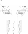
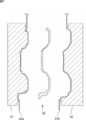
- FIG. 7 is a view showing an example of a molding machine 1 that can be used in the method of manufacturing the structure 30. It is a figure showing a drooping process, and is an expanded sectional view near the 1st and 2nd metallic molds 21 and 22 and the 1st and 2nd resin sheets 23a and 23b. It is a figure showing a mode that 1st and 2nd resin sheet 23a, b was contact
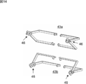
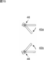
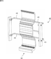
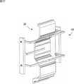
- FIG. 10 It is a rear perspective view of the bending jig 40 of one embodiment of the present invention. It is a figure showing a mode that 1st and 2nd arm support part 43a, 43b of the bending jig 40 was rotated. It is a figure showing the positional relationship in rotation back and front of 1st and 2nd arm support part 43a, 43b. It is a side view of FIG. It is a front perspective view showing a mode that the insert member 34 was attached to the bending jig 40. As shown in FIG. Here, the frame 41 and the arm attachment portion 42 of the bending jig 40 are omitted to improve the visibility. The same applies to FIGS. 17 to 20 below. FIG.
- FIG. 10 is a rear perspective view showing a state in which the insert member 34 is attached to the bending jig 40. It is a front perspective view showing a mode that the 1st and 2nd arm support parts 43a and 43b were rotated from the state of FIG. 16, and the insert member 34 was curved.
- FIG. 19 is a rear perspective view of FIG. 18; It is a rear perspective view showing positional relationship of insert member 34 and 1st and 2nd arm supporters 43a and 43b before and behind rotation of 1st and 2nd arm supporters 43a and 43b. It is a figure showing a mode that the curve of the insert member 34 was cancelled
- FIG. 3 is a plan cross-sectional view of a structure 30.
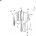
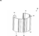
- FIG. 3 is a front and rear perspective view of a structure 30; The structure 30 in this state is curved to form the shape shown in FIG.
- FIG. 7 is a rear perspective view of the structure 30. The structure 30 in this state is curved to form the shape shown in FIG.
- the structure 30 As shown in FIGS. 1 to 3, the structure 30 according to the embodiment of the present invention includes a base 36, a first arm 37 and a second arm 38. The first arm 37 and the second arm 38 are respectively connected to the base 36 via the hinges 35.
- the insert member 34 is covered with an inner surface 31 and an outer surface 32 formed by first and second resin sheets 23a and 23b described later.
- the inner surface 31 and the outer surface 32 are connected by the connecting surface 33.
- the material of the insert member 34 is not particularly limited, but is preferably a foam.
- the container By combining the other members with the upper and lower portions of the structure 30, the container can be used as a cooler box or the like.
- the molding machine 1 includes a resin supply device 2, a T die 18, and first and second molds 21 and 22.
- the resin supply device 2 includes a hopper 12, an extruder 13, and an accumulator 17.
- the extruder 13 and the accumulator 17 are connected via a connecting pipe 25.
- the accumulator 17 and the T-die 18 are connected via a connecting pipe 27.
- the hopper 12 is used to introduce the raw material resin 11 into the cylinder 13 a of the extruder 13.
- the form of the raw material resin 11 is not particularly limited, but is usually in the form of pellets.
- the raw material resin is, for example, a thermoplastic resin such as polyolefin, and examples of the polyolefin include low density polyethylene, linear low density polyethylene, high density polyethylene, polypropylene, ethylene-propylene copolymer and mixtures thereof.
- the raw material resin 11 is introduced into the cylinder 13a from the hopper 12 and then melted by being heated in the cylinder 13a to become a molten resin.
- the screw is disposed in the cylinder 13a and is conveyed while kneading the molten resin by its rotation.
- a gear device is provided at the proximal end of the screw, and the screw device is rotationally driven by the gear device.
- the number of screws disposed in the cylinder 13a may be one or two or more.
- the foamed resin obtained by melt-kneading the raw resin and the foaming agent is extruded from the resin extrusion port of the cylinder 13 a and is injected into the accumulator 17 through the connecting pipe 25.
- the accumulator 17 includes a cylinder 17a and a piston 17b slidable therein, and the molten resin 11a can be stored in the cylinder 17a. Then, by moving the piston 17b after a predetermined amount of foamed resin is stored in the cylinder 17a, the foamed resin is pushed out from the slit provided in the T die 18 through the connection pipe 27 and suspended, thereby the first and second Resin sheets 23a and 23b are formed.
- the first and second resin sheets 23 a and 23 b are guided between the first and second molds 21 and 22.
- the first mold 21 is provided with a large number of vacuum suction holes (not shown), and the first resin sheet 23 a is vacuum suctioned along the cavity 21 b of the first mold 21.
- the cavity 21b has a shape having a recess 21c and a protrusion 21e, and a pinch-off portion 21d is provided to surround the recess 21c and the protrusion 21e.
- the recess 21 c includes an inclined surface 21 cs which is inclined such that the cross-sectional area of the recess 21 c becomes narrower toward the bottom of the recess 21 c.
- the second mold 22 is provided with a large number of vacuum suction holes (not shown), and the second resin sheet 23b is vacuum suctioned and shaped into a shape along the cavity 22b of the second mold 22. Is possible.
- the cavity 22b has a shape having a convex portion 22c and a concave portion 22e, and a pinch off portion 21d is provided so as to surround the convex portion 22c and the concave portion 22e.
- Method of Manufacturing Structure 30 a method of manufacturing the structure 30 according to the embodiment of the present invention will be described with reference to FIGS. 4 to 9, 21 and 22.
- the method of the present embodiment comprises a drooping step, a shaping step, an inserting step, and a clamping step. The details will be described below.
- the insert member 34 is disposed between the first and second molds 21 and 22.
- the insert member 34 is configured by the base 36, the first arm 37 and the second arm 38.
- the first arm 37 and the second arm 38 are respectively connected to the base 36 via the hinges 35.
- the insert member 34 includes an inclined surface 39.
- the inclined surface 39 of the insert member 34 is parallel to the inclined surface 21 cs of the recess 21 c in a state in which the insert member 34 is not curved.
- the insert member 34 is provided with the convex part 36c.
- the convex portion 36 c is provided on the base 36.
- the convex portion 36 c has a substantially complementary shape to the concave portion 21 c.
- the first and second resin sheets 23 a and 23 b formed by extruding and dropping the foamed resin in a molten state from the slit of the T die 18 are suspended between the first and second molds 21 and 22.
- direct vacuum forming is performed using the first and second resin sheets 23a and 23b extruded from the T die 18 as they are, so the first and second resin sheets 23a and 23b are at room temperature before forming.
- the first and second resin sheets 23a and 23b that are solidified are not heated before molding.
- the insert member 34 is illustrated between the first and second resin sheets 23a and 23b during the drooping step, but in the drooping step, the insert member 34 is made to stand by at another place. You may leave it.
- the insert member 34 is bent.
- the insert member 34 is curved such that the first mold 21 side is convex (convex formed by the convex portion 36 c).
- the insert member 34 is curved so that the inclined surface 39 of the insert member 34 is not parallel to the inclined surface 21cs of the recess 21c.
- the insert member 34 is curved by pivoting the first arm 37 and the second arm 38 such that the first arm 37 and the second arm 38 are separated from the first mold 21.
- the fixing includes welding of the resin in a molten state and another resin (foam).
- the insert member 34 is curved so that the width of the convex surface of the convex portion 36c is smaller than the width of the concave portion 21c in side view, the corners of the inclined surface 21cs and the inclined surface 39 make contact Can be reduced.
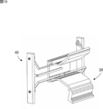
- the bending jig 40 includes a base support 44, a first arm support 43a, and a second arm support 43b.
- the base support portion 44, the first arm support portion 43a and the second arm support portion 43b are each L-shaped, and the base 36, the first arm 37 and the second arm 38 are attracted from the second mold 22 side
- the suction unit 45 is provided.
- the first arm support portion 43a and the second arm support portion 43b are separate members, and the second arm support portions 43b of the first arm support portions 43a extend so as to face each other.
- suction part 45 is not specifically limited,
- the base 36, the 1st arm 37, and the 2nd arm 38 can be adsorb
- the base support portion 44, the first arm support portion 43a and the second arm support portion 43b are attached to the arm attachment portion 42, respectively.
- the first arm support portion 43 a and the second arm support portion 43 b are attached to the arm attachment portion 42 via the rotation member 46.
- the rotation member 46 is configured to be rotatable by a motor (not shown), whereby the first arm support portion 43a and the second arm support portion 43b rotate.
- the arm attachment portion 42 is attached to the H-shaped frame 41 in a front view.
- FIG. 13 shows a state in which the first arm support 43a and the second arm support 43b are rotated.
- the first arm support portion 43a and the second arm support portion 43b are L-shaped, so that they are rotated by the rotating member 46 in the vertical direction in the side view
- the adsorbing portions 45 approach each other, and the adsorbing portions 45 move so as to approach the first mold 21 in the front-rear direction in side view.
- FIG. 16 and 17 are perspective views showing a state in which the insert member 34 is attached to the bending jig 40.
- FIG. 16 and later the frame 41 and the arm attachment portion 42 are not shown in order to improve the visibility.
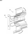
- the base 36 of the insert member 34, the first arm 37 and the second arm 38 are provided by the suction portion 45 provided on the base support portion 44, the first arm support portion 43 a and the second arm support portion 43 b. Is adsorbed from the second mold 22 side.
- FIG. 19 is a rear perspective view showing the positional relationship between the insert member 34 and the first and second arm support portions 43a and 43b before and after bending.
- the insert member 34 is bent using the bending jig 40. Note that the bending jig 40 is not shown in FIGS. 4 to 9 and 21 for the purpose of improving the visibility.
- the bending jig 40 is removed from the insert member 34, and the bending of the insert member 34 is released to fix the portions other than the convex portion 36c of the insert member 34 to the first resin sheet 23a.
- the convex portion 36c of the insert member 34 is first disposed in the concave portion 21c, and the convex surface of the convex portion 36c is fixed to the first resin sheet 23a, whereby the alignment between the insert member 34 and the first resin sheet 23a is It will be easier.
- the curvature of the insert member 34 is released, and the location other than the convex portion 36c is fixed to the first resin sheet 23a, thereby reducing the mixing of air between the insert member 34 and the first resin sheet 23a.
- the first and second molds 21 and 22 are clamped.
- the first resin sheet 23 a becomes the inner surface 31
- the second resin sheet 23 b becomes the outer surface 32.
- the molded object of the shape along the cavities 21b and 22b of the 1st and 2nd metal molds 21 and 22 is obtained.
- the molded body is taken out from the first and second molds 21 and 22 and the burrs 26 are removed to obtain the structure 30 shown in FIG.
- ⁇ Modification> Contrary to the mode shown in FIGS. 8, 9 and 21, first, a part of the insert member 34 is fixed to the convex portion 22 c side of the second mold 22, and the first arm 37 and the second arm 38 are By narrowing, the insert member 34 may be inserted into the second mold 22 and then the first and second molds 21 and 22 may be clamped.
- the present invention can also be practiced in the following modes.
- the second resin sheet 23b constituting the hinge portion 35 is compressed by the second mold 22 in the mold clamping step.
- a cut is made in the structure 30 after the clamping process.
- the base 36, the first arm 37, and the second arm 38 are configured as separate members.
- Molding machine 2 Resin supply device 11: Raw resin 11a: Melt resin 12: Hopper 13: Extruder 13a: Cylinder 17: Accumulator 17a: Cylinder 17b: Piston 18: T die , 21: first mold, 21b: cavity, 21c: recess, 21cs: inclined surface, 21d: pinch off portion, 21e: protrusion, 22: second die, 22b: cavity, 22c: protrusion, 22e: recess , 23a: first resin sheet, 23b: second resin sheet, 25: connection pipe, 26: burr, 27: connection pipe, 30: structure, 31: inner surface, 32: outer surface, 33: connection surface, 34: insert Member 35: Hinge part 36: Base body 36c: Convex part 37: First arm 38: Second arm 39: Inclined surface 40: Curved jig 41: Frame 42: Arm attachment part 43a The first arm support, 43 b: second arm support, 44: base body supporting section, 45: suction portion, 46: rotary member
Landscapes
- Engineering & Computer Science (AREA)
- Mechanical Engineering (AREA)
- Moulds For Moulding Plastics Or The Like (AREA)
- Casting Or Compression Moulding Of Plastics Or The Like (AREA)
- Blow-Moulding Or Thermoforming Of Plastics Or The Like (AREA)
Abstract
インサート部材と樹脂シートの間に空気が混入することを低減することができる構造体の製造方法を提供する。 本発明によれば、垂下工程と、賦形工程と、インサート工程と、型締め工程を備え、前記垂下工程では、第1及び第2金型の間に第1及び第2樹脂シートを垂下させ、前記賦形工程では、第1樹脂シートを第1金型のキャビティの内面に沿った形状に賦形し、前記インサート工程では、インサート部材を湾曲させた状態で前記インサート部材の一部を第1樹脂シートに固着させ、前記型締め工程では、第1及び第2金型を型締めする、構造体の製造方法が提供される。
Description
本発明は、構造体の製造方法に関する。
特許文献1には、発泡樹脂基材と、発泡樹脂基材の内面にインサートされたインサート部材により形成される自動車用内装部品が開示されている。ここで、特許文献1では、発泡樹脂基材の溶着面にインサート部材を溶着し、上下金型の型締め圧によりインサート部材を発泡樹脂基材の裏面に固着することにより、かかる自動車用内装部品が製造される。
しかし、インサート部材を樹脂基材に固着する際に、両部材の面同士が接触する態様では位置合わせに高い精度が求められる。これにより、位置合わせがわずかにずれた場合には、両部材の面の間に空気が混入し、完成品の精度が低下する場合がある。
本発明はこのような事情に鑑みてなされたものであり、インサート部材と樹脂シートの間に空気が混入することを低減することができる構造体の製造方法を提供するものである。
本発明によれば、垂下工程と、賦形工程と、インサート工程と、型締め工程を備え、前記垂下工程では、第1及び第2金型の間に第1及び第2樹脂シートを垂下させ、前記賦形工程では、第1樹脂シートを第1金型のキャビティの内面に沿った形状に賦形し、前記インサート工程では、インサート部材を湾曲させた状態で前記インサート部材の一部を第1樹脂シートに固着させ、前記型締め工程では、第1及び第2金型を型締めする、構造体の製造方法が提供される。
本発明に係る構造体は、垂下工程と、賦形工程と、インサート工程と、型締め工程を備える。インサート工程では、インサート部材を湾曲させた状態でインサート部材の一部を第1樹脂シートに固着させる。これにより、インサート部材と第1樹脂シートが面で接触することがなく、インサート部材と第1樹脂シートの間に空気が混入することを低減することができる。
以下、本発明の種々の実施形態を例示する。以下に示す実施形態は互いに組み合わせ可能である。
好ましくは、前記インサート部材は、第1金型側が凸面となるように湾曲される。
好ましくは、第1金型のキャビティは、凹部を備え、前記インサート部材は、凸部を備え、前記インサート部材は、前記凸部が前記凹部内に配置されるように、第1樹脂シートに固着される。
好ましくは、前記凸部は、前記凹部と略相補形状である。
好ましくは、前記凹部は、前記凹部の底に向かって前記凹部の断面積が狭くなるように傾斜する傾斜面を備える。
好ましくは、前記インサート部材は、傾斜面を備え、前記インサート部材の傾斜面は、前記インサート部材を湾曲させていない状態で前記凹部の傾斜面に平行であり、前記インサート部材は、前記インサート部材の傾斜面が前記凹部の傾斜面に非平行になるように湾曲される。
好ましくは、前記インサート部材は、基体、第1アーム及び第2アームを備え、前記凸部は、前記基体に設けられ、第1及び第2アームはそれぞれ、ヒンジ部を介して前記基体に連結されており、前記インサート部材は、第1及び第2アームが第1金型から離れるように第1及び第2アームを回動させることによって湾曲される。
好ましくは、前記インサート部材は、湾曲治具を用いて湾曲され、前記湾曲治具は、基体支持部、第1アーム支持部及び第2アーム支持部を備え、前記インサート部材を湾曲させる際に、前記基体支持部、第1アーム支持部及び第2アーム支持部がそれぞれ基体、第1アーム及び第2アームを支持し、前記インサート部材は、前記基体支持部で前記基体を支持した状態で第1及び第2アーム支持部を回動させることによって湾曲される。
好ましくは、前記基体支持部、第1アーム支持部及び第2アーム支持部は、それぞれ、基体、第1アーム及び第2アームを第2金型側から吸着する吸着部を備える。
好ましくは、前記インサート部材は、第1金型側が凸面となるように湾曲される。
好ましくは、第1金型のキャビティは、凹部を備え、前記インサート部材は、凸部を備え、前記インサート部材は、前記凸部が前記凹部内に配置されるように、第1樹脂シートに固着される。
好ましくは、前記凸部は、前記凹部と略相補形状である。
好ましくは、前記凹部は、前記凹部の底に向かって前記凹部の断面積が狭くなるように傾斜する傾斜面を備える。
好ましくは、前記インサート部材は、傾斜面を備え、前記インサート部材の傾斜面は、前記インサート部材を湾曲させていない状態で前記凹部の傾斜面に平行であり、前記インサート部材は、前記インサート部材の傾斜面が前記凹部の傾斜面に非平行になるように湾曲される。
好ましくは、前記インサート部材は、基体、第1アーム及び第2アームを備え、前記凸部は、前記基体に設けられ、第1及び第2アームはそれぞれ、ヒンジ部を介して前記基体に連結されており、前記インサート部材は、第1及び第2アームが第1金型から離れるように第1及び第2アームを回動させることによって湾曲される。
好ましくは、前記インサート部材は、湾曲治具を用いて湾曲され、前記湾曲治具は、基体支持部、第1アーム支持部及び第2アーム支持部を備え、前記インサート部材を湾曲させる際に、前記基体支持部、第1アーム支持部及び第2アーム支持部がそれぞれ基体、第1アーム及び第2アームを支持し、前記インサート部材は、前記基体支持部で前記基体を支持した状態で第1及び第2アーム支持部を回動させることによって湾曲される。
好ましくは、前記基体支持部、第1アーム支持部及び第2アーム支持部は、それぞれ、基体、第1アーム及び第2アームを第2金型側から吸着する吸着部を備える。
以下、本発明の実施形態について説明する。以下に示す実施形態中で示した各種特徴事項は、互いに組み合わせ可能である。また、各特徴事項について独立して発明が成立する。
1.構造体30
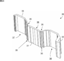
図1~図3に示すように、本発明の一実施形態の構造体30は、基体36、第1アーム37及び第2アーム38により構成される。第1アーム37及び第2アーム38はそれぞれ、ヒンジ部35を介して基体36に連結されている。
図1~図3に示すように、本発明の一実施形態の構造体30は、基体36、第1アーム37及び第2アーム38により構成される。第1アーム37及び第2アーム38はそれぞれ、ヒンジ部35を介して基体36に連結されている。
構造体30は、図1及び図23に示すように、後述の第1及び第2樹脂シート23a,23bにより形成された内面31及び外面32によりインサート部材34が覆われている。内面31と外面32は、連結面33により連結される。ここで、インサート部材34の材質は特に限定されないが、発泡体であることが好ましい。
かかる構造体30の上下に他の部材を組み合わせることにより、クーラーボックス等の容器として利用することができる。
2.成形機1の構成
次に、図4~図9、図21及び図22を用いて、本発明の一実施形態の構造体30の製造方法の実施に利用可能な成形機1について説明する。成形機1は、樹脂供給装置2と、Tダイ18と、第1及び第2金型21,22を備える。樹脂供給装置2は、ホッパー12と、押出機13と、アキュームレータ17を備える。押出機13とアキュームレータ17は、連結管25を介して連結される。アキュームレータ17とTダイ18は、連結管27を介して連結される。以下、各構成について詳細に説明する。
次に、図4~図9、図21及び図22を用いて、本発明の一実施形態の構造体30の製造方法の実施に利用可能な成形機1について説明する。成形機1は、樹脂供給装置2と、Tダイ18と、第1及び第2金型21,22を備える。樹脂供給装置2は、ホッパー12と、押出機13と、アキュームレータ17を備える。押出機13とアキュームレータ17は、連結管25を介して連結される。アキュームレータ17とTダイ18は、連結管27を介して連結される。以下、各構成について詳細に説明する。
<ホッパー12,押出機13>
ホッパー12は、原料樹脂11を押出機13のシリンダ13a内に投入するために用いられる。原料樹脂11の形態は、特に限定されないが、通常は、ペレット状である。原料樹脂は、例えばポリオレフィンなどの熱可塑性樹脂であり、ポリオレフィンとしては、低密度ポリエチレン、直鎖状低密度ポリエチレン、高密度ポリエチレン、ポリプロピレン、エチレン-プロピレン共重合体及びその混合物などが挙げられる。原料樹脂11は、ホッパー12からシリンダ13a内に投入された後、シリンダ13a内で加熱されることによって溶融されて溶融樹脂になる。また、シリンダ13a内に配置されたスクリューの回転によってシリンダ13aの先端に向けて搬送される。スクリューは、シリンダ13a内に配置され、その回転によって溶融樹脂を混練しながら搬送する。スクリューの基端にはギア装置が設けられており、ギア装置によってスクリューが回転駆動される。シリンダ13a内に配置されるスクリューの数は、1本でもよく、2本以上であってもよい。
ホッパー12は、原料樹脂11を押出機13のシリンダ13a内に投入するために用いられる。原料樹脂11の形態は、特に限定されないが、通常は、ペレット状である。原料樹脂は、例えばポリオレフィンなどの熱可塑性樹脂であり、ポリオレフィンとしては、低密度ポリエチレン、直鎖状低密度ポリエチレン、高密度ポリエチレン、ポリプロピレン、エチレン-プロピレン共重合体及びその混合物などが挙げられる。原料樹脂11は、ホッパー12からシリンダ13a内に投入された後、シリンダ13a内で加熱されることによって溶融されて溶融樹脂になる。また、シリンダ13a内に配置されたスクリューの回転によってシリンダ13aの先端に向けて搬送される。スクリューは、シリンダ13a内に配置され、その回転によって溶融樹脂を混練しながら搬送する。スクリューの基端にはギア装置が設けられており、ギア装置によってスクリューが回転駆動される。シリンダ13a内に配置されるスクリューの数は、1本でもよく、2本以上であってもよい。
<アキュームレータ17、Tダイ18>
原料樹脂と発泡剤が溶融混練されてなる発泡樹脂は、シリンダ13aの樹脂押出口から押し出され、連結管25を通じてアキュームレータ17内に注入される。アキュームレータ17は、シリンダ17aとその内部で摺動可能なピストン17bを備えており、シリンダ17a内に溶融樹脂11aが貯留可能になっている。そして、シリンダ17a内に発泡樹脂が所定量貯留された後にピストン17bを移動させることによって、連結管27を通じて発泡樹脂をTダイ18内に設けられたスリットから押し出して垂下させて第1及び第2樹脂シート23a,23bを形成する。
原料樹脂と発泡剤が溶融混練されてなる発泡樹脂は、シリンダ13aの樹脂押出口から押し出され、連結管25を通じてアキュームレータ17内に注入される。アキュームレータ17は、シリンダ17aとその内部で摺動可能なピストン17bを備えており、シリンダ17a内に溶融樹脂11aが貯留可能になっている。そして、シリンダ17a内に発泡樹脂が所定量貯留された後にピストン17bを移動させることによって、連結管27を通じて発泡樹脂をTダイ18内に設けられたスリットから押し出して垂下させて第1及び第2樹脂シート23a,23bを形成する。
<第1及び第2金型21,22>
第1及び第2樹脂シート23a,23bは、第1及び第2金型21,22間に導かれる。図5に示すように、第1金型21には、多数の減圧吸引孔(不図示)が設けられており、第1樹脂シート23aを減圧吸引して第1金型21のキャビティ21bに沿った形状に賦形することが可能になっている。キャビティ21bは、凹部21c及び凸部21eを有する形状になっており、凹部21c及び凸部21eを取り囲むようにピンチオフ部21dが設けられている。また、凹部21cは、凹部21cの底に向かって凹部21cの断面積が狭くなるように傾斜する傾斜面21csを備える。第2金型22には、多数の減圧吸引孔(不図示)が設けられており、第2樹脂シート23bを減圧吸引して第2金型22のキャビティ22bに沿った形状に賦形することが可能になっている。キャビティ22bは、凸部22c及び凹部22eを有する形状になっており、凸部22c及び凹部22eを取り囲むようにピンチオフ部21dが設けられている。
第1及び第2樹脂シート23a,23bは、第1及び第2金型21,22間に導かれる。図5に示すように、第1金型21には、多数の減圧吸引孔(不図示)が設けられており、第1樹脂シート23aを減圧吸引して第1金型21のキャビティ21bに沿った形状に賦形することが可能になっている。キャビティ21bは、凹部21c及び凸部21eを有する形状になっており、凹部21c及び凸部21eを取り囲むようにピンチオフ部21dが設けられている。また、凹部21cは、凹部21cの底に向かって凹部21cの断面積が狭くなるように傾斜する傾斜面21csを備える。第2金型22には、多数の減圧吸引孔(不図示)が設けられており、第2樹脂シート23bを減圧吸引して第2金型22のキャビティ22bに沿った形状に賦形することが可能になっている。キャビティ22bは、凸部22c及び凹部22eを有する形状になっており、凸部22c及び凹部22eを取り囲むようにピンチオフ部21dが設けられている。
3.構造体30の製造方法
ここで、図4~図9、図21及び図22を用いて、本発明の一実施形態の構造体30の製造方法について説明する。本実施形態の方法は、垂下工程と、賦形工程と、インサート工程と、型締め工程を備える。以下、詳細に説明する。
ここで、図4~図9、図21及び図22を用いて、本発明の一実施形態の構造体30の製造方法について説明する。本実施形態の方法は、垂下工程と、賦形工程と、インサート工程と、型締め工程を備える。以下、詳細に説明する。
3.1 垂下工程
垂下工程では、図5に示すように、インサート部材34を、第1及び第2金型21,22間に配置する。ここで、本実施形態では、インサート部材34は、基体36、第1アーム37及び第2アーム38により構成される。第1アーム37及び第2アーム38はそれぞれ、ヒンジ部35を介して基体36に連結されている。また、インサート部材34は、傾斜面39を備える。本実施形態では、インサート部材34の傾斜面39は、インサート部材34を湾曲させていない状態で凹部21cの傾斜面21csに平行である。また、インサート部材34は凸部36cを備える。本実施形態では、凸部36cは基体36に設けられる。ここで、凸部36cは、凹部21cと略相補形状である。
垂下工程では、図5に示すように、インサート部材34を、第1及び第2金型21,22間に配置する。ここで、本実施形態では、インサート部材34は、基体36、第1アーム37及び第2アーム38により構成される。第1アーム37及び第2アーム38はそれぞれ、ヒンジ部35を介して基体36に連結されている。また、インサート部材34は、傾斜面39を備える。本実施形態では、インサート部材34の傾斜面39は、インサート部材34を湾曲させていない状態で凹部21cの傾斜面21csに平行である。また、インサート部材34は凸部36cを備える。本実施形態では、凸部36cは基体36に設けられる。ここで、凸部36cは、凹部21cと略相補形状である。
そして、第1及び第2金型21,22間に、溶融状態の発泡樹脂をTダイ18のスリットから押し出して垂下させて形成した第1及び第2樹脂シート23a,23bを垂下する。本実施形態では、Tダイ18から押し出された第1及び第2樹脂シート23a,23bをそのまま使用するダイレクト真空成形が行われるので、第1及び第2樹脂シート23a,23bは、成形前に室温にまで冷却されて固化されることがなく、固化された第1及び第2樹脂シート23a,23bが成形前に加熱されることもない。ここで、図5では、垂下工程中において、第1及び第2樹脂シート23a,23bの間にインサート部材34を図示しているが、垂下工程では、インサート部材34を他の場所に待機させておいてもよい。
3.2 賦形工程
次に、図6及び図7に示すように、第1及び第2樹脂シート23a,23bをそれぞれ第1及び第2金型21,22の一部に当接させた後、第1及び第2金型21,22の両方によって第1及び第2樹脂シート23a,23bを減圧吸引して第1及び第2金型21,22のキャビティ21bに沿った形状に賦形する。
次に、図6及び図7に示すように、第1及び第2樹脂シート23a,23bをそれぞれ第1及び第2金型21,22の一部に当接させた後、第1及び第2金型21,22の両方によって第1及び第2樹脂シート23a,23bを減圧吸引して第1及び第2金型21,22のキャビティ21bに沿った形状に賦形する。
3.3 インサート工程
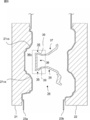
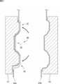
次に、図8に示すように、インサート部材34を湾曲させる。ここで、本実施形態では、インサート部材34は、第1金型21側が凸面(凸部36cにより形成される凸面)となるように湾曲される。図8の例では、インサート部材34は、インサート部材34の傾斜面39が凹部21cの傾斜面21csに非平行になるように湾曲される。また、他の表現では、インサート部材34は、第1アーム37及び第2アーム38が第1金型21から離れるように第1アーム37及び第2アーム38を回動させることによって湾曲される。
次に、図8に示すように、インサート部材34を湾曲させる。ここで、本実施形態では、インサート部材34は、第1金型21側が凸面(凸部36cにより形成される凸面)となるように湾曲される。図8の例では、インサート部材34は、インサート部材34の傾斜面39が凹部21cの傾斜面21csに非平行になるように湾曲される。また、他の表現では、インサート部材34は、第1アーム37及び第2アーム38が第1金型21から離れるように第1アーム37及び第2アーム38を回動させることによって湾曲される。
インサート部材34を湾曲させた状態で、インサート部材34の一部を第1樹脂シート23aに固着させる。このとき、インサート部材34は、凸部36cが凹部21c内に配置されるように、第1樹脂シート23aに固着される。ここで、本実施形態では、固着とは、溶融状態の樹脂と他の樹脂(発泡体)が溶着することを含む。
ここで、本実施形態では、側面視において、凹部21cの幅よりも凸部36cの凸面の幅が小さくなるようにインサート部材34が湾曲されるので、傾斜面21csと傾斜面39の角が接触することを低減することができる。
<湾曲治具40>
ここで、図10~図20を用いて、インサート工程におけるインサート部材34を湾曲する湾曲治具40について説明する。
ここで、図10~図20を用いて、インサート工程におけるインサート部材34を湾曲する湾曲治具40について説明する。
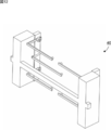
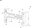
図10~図12に示すように、湾曲治具40は、基体支持部44、第1アーム支持部43a及び第2アーム支持部43bを備える。基体支持部44、第1アーム支持部43a及び第2アーム支持部43bはそれぞれ、L字型の形状であり、基体36、第1アーム37及び第2アーム38を第2金型22側から吸着する吸着部45を備える。また、第1アーム支持部43a及び第2アーム支持部43bは別部材であり、第1アーム支持部43a同士、の第2アーム支持部43b同士は互いに対向するように延在している。このように、第1アーム支持部43a及び第2アーム支持部43bを別部材とすることにより、それぞれの回転がわずかにずれた場合でも、回転のずれを吸収できるので、回転軸がぶれることを低減できる。吸着部45の構成は特に限定されないが、例えば不図示の減圧装置を用いて基体36、第1アーム37及び第2アーム38を吸着することができる。そして、インサート部材34を湾曲させる際に、基体支持部44、第1アーム支持部43a及び第2アーム支持部43bがそれぞれ基体36、第1アーム37及び第2アーム38を支持する。
基体支持部44、第1アーム支持部43a及び第2アーム支持部43bはそれぞれ、アーム取付部42に取り付けられる。ここで、第1アーム支持部43a及び第2アーム支持部43bは、回転部材46を介してアーム取付部42に取り付けられる。回転部材46は、不図示のモーターにより回転可能に構成され、これにより、第1アーム支持部43a及び第2アーム支持部43bが回動する。アーム取付部42は、正面視においてH字形状のフレーム41に取り付けられる。
図13は第1アーム支持部43a及び第2アーム支持部43bを回動させた状態である。図14及び図15に示すように、第1アーム支持部43a及び第2アーム支持部43bはL字形状となっているため、回転部材46により回動されることで、側面視における上下方向において吸着部45が互いに近接し、側面視における前後方向において吸着部45が第1金型21に接近するように移動する。
図16及び図17は、湾曲治具40にインサート部材34を取り付けた状態を表す斜視図である。ここで、図16以降において、視認性の向上のため、フレーム41及びアーム取付部42は図示を省略している。
図17に示すように、基体支持部44、第1アーム支持部43a及び第2アーム支持部43bに設けられた吸着部45により、インサート部材34の基体36、第1アーム37及び第2アーム38が第2金型22側から吸着される。
そして、図18に示すように、インサート部材34は、基体支持部44で基体36を支持した状態で第1アーム支持部43a及び第2アーム支持部43bを回動させることによって湾曲される。図19は、湾曲前後におけるインサート部材34及び第1及び第2アーム支持部43a,43bの位置関係を表す背面斜視図である。このように、本実施形態では、インサート部材34は、湾曲治具40を用いて湾曲される。なお、視認性の向上のため、図4~図9及び図21において、湾曲治具40の図示を省略している。
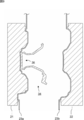
次に、図21に示すように、湾曲治具40をインサート部材34から取り外し、インサート部材34の湾曲を解除することにより、インサート部材34の凸部36c以外の箇所を第1樹脂シート23aに固着させる。このように、まずインサート部材34の凸部36cを凹部21c内に配置し、凸部36cの凸面を第1樹脂シート23aに固着させることにより、インサート部材34と第1樹脂シート23aの位置合わせが容易になる。そして、インサート部材34の湾曲を解除し、凸部36c以外の箇所を第1樹脂シート23aと固着することで、インサート部材34と第1樹脂シート23aの間に空気が混入することを低減することができる。ここで、湾曲を解除した後に、インサート部材34を第1金型21に押し付ける工程があってもよい。これにより、インサート部材34と1樹脂シート23aをより強固に固着することができる。
3.4 型締工程
この工程では、図22に示すように、第1及び第2金型21,22を型締めする。かかる型締めにより、第1樹脂シート23aが内面31に、第2樹脂シート23bが外面32となる。そして、第1及び第2金型21,22のキャビティ21b,22bに沿った形状の成形体が得られる。そして、第1及び第2金型21,22から成形体を取り出し、バリ26を除去することによって、図23に示される構造体30が得られる。
この工程では、図22に示すように、第1及び第2金型21,22を型締めする。かかる型締めにより、第1樹脂シート23aが内面31に、第2樹脂シート23bが外面32となる。そして、第1及び第2金型21,22のキャビティ21b,22bに沿った形状の成形体が得られる。そして、第1及び第2金型21,22から成形体を取り出し、バリ26を除去することによって、図23に示される構造体30が得られる。
図24及び図25は、上記の工程を経て完成した構造体30である。この状態の構造体30を、ヒンジ部35を境に第1アーム37及び第2アーム38を基体36に対して湾曲させることにより、図1~図3に示される状態となる。
<変形例>
図8、図9及び図21に示される態様とは逆に、まず、第2金型22の凸部22c側にインサート部材34の一部を固着させ、第1アーム37及び第2アーム38を狭めることにより、インサート部材34を第2金型22にインサートしてから、第1及び第2金型21,22を片締めしてもよい。
図8、図9及び図21に示される態様とは逆に、まず、第2金型22の凸部22c側にインサート部材34の一部を固着させ、第1アーム37及び第2アーム38を狭めることにより、インサート部材34を第2金型22にインサートしてから、第1及び第2金型21,22を片締めしてもよい。
<その他>
本発明は、以下の態様でも実施可能である。
・ヒンジ部35を形成するために、型締工程において第2金型22によりヒンジ部35を構成する第2樹脂シート23bをコンプレッションする。
・ヒンジ部35を形成するために、型締工程後の構造体30に切り込みを入れる。
・基体36、第1アーム37及び第2アーム38をそれぞれ別部材で構成する。
本発明は、以下の態様でも実施可能である。
・ヒンジ部35を形成するために、型締工程において第2金型22によりヒンジ部35を構成する第2樹脂シート23bをコンプレッションする。
・ヒンジ部35を形成するために、型締工程後の構造体30に切り込みを入れる。
・基体36、第1アーム37及び第2アーム38をそれぞれ別部材で構成する。
1:成形機、2:樹脂供給装置、11:原料樹脂、11a:溶融樹脂、12:ホッパー、13:押出機、13a:シリンダ、17:アキュームレータ、17a:シリンダ、17b:ピストン、18:Tダイ、21:第1金型、21b:キャビティ、21c:凹部、21cs:傾斜面、21d:ピンチオフ部、21e:凸部、22:第2金型、22b:キャビティ、22c:凸部、22e:凹部、23a:第1樹脂シート、23b:第2樹脂シート、25:連結管、26:バリ、27:連結管、30:構造体、31:内面、32:外面、33:連結面、34:インサート部材、35:ヒンジ部、36:基体、36c:凸部、37:第1アーム、38:第2アーム、39:傾斜面、40:湾曲治具、41:フレーム、42:アーム取付部、43a:第1アーム支持部、43b:第2アーム支持部、44:基体支持部、45:吸着部、46:回転部材
Claims (9)
- 垂下工程と、賦形工程と、インサート工程と、型締め工程を備え、
前記垂下工程では、第1及び第2金型の間に第1及び第2樹脂シートを垂下させ、
前記賦形工程では、第1樹脂シートを第1金型のキャビティの内面に沿った形状に賦形し、
前記インサート工程では、インサート部材を湾曲させた状態で前記インサート部材の一部を第1樹脂シートに固着させ、
前記型締め工程では、第1及び第2金型を型締めする、
構造体の製造方法。 - 前記インサート部材は、第1金型側が凸面となるように湾曲される、
請求項1に記載の構造体の製造方法。 - 第1金型のキャビティは、凹部を備え、
前記インサート部材は、凸部を備え、
前記インサート部材は、前記凸部が前記凹部内に配置されるように、第1樹脂シートに固着される、請求項1又は請求項2に記載の方法。 - 前記凸部は、前記凹部と略相補形状である、請求項3に記載の方法。
- 前記凹部は、前記凹部の底に向かって前記凹部の断面積が狭くなるように傾斜する傾斜面を備える、請求項3又は請求項4に記載の方法。
- 前記インサート部材は、傾斜面を備え、
前記インサート部材の傾斜面は、前記インサート部材を湾曲させていない状態で前記凹部の傾斜面に平行であり、
前記インサート部材は、前記インサート部材の傾斜面が前記凹部の傾斜面に非平行になるように湾曲される、請求項3~請求項5の何れか1つに記載の方法。 - 前記インサート部材は、基体、第1アーム及び第2アームを備え、
前記凸部は、前記基体に設けられ、
第1及び第2アームはそれぞれ、ヒンジ部を介して前記基体に連結されており、
前記インサート部材は、第1及び第2アームが第1金型から離れるように第1及び第2アームを回動させることによって湾曲される、請求項3~請求項6の何れか1つに記載の方法。 - 前記インサート部材は、湾曲治具を用いて湾曲され、
前記湾曲治具は、基体支持部、第1アーム支持部及び第2アーム支持部を備え、
前記インサート部材を湾曲させる際に、前記基体支持部、第1アーム支持部及び第2アーム支持部がそれぞれ基体、第1アーム及び第2アームを支持し、
前記インサート部材は、前記基体支持部で前記基体を支持した状態で第1及び第2アーム支持部を回動させることによって湾曲される、請求項7に記載の方法。 - 前記基体支持部、第1アーム支持部及び第2アーム支持部は、それぞれ、基体、第1アーム及び第2アームを第2金型側から吸着する吸着部を備える、請求項8に記載の方法。
Applications Claiming Priority (2)
| Application Number | Priority Date | Filing Date | Title |
|---|---|---|---|
| JP2017127759A JP6908837B2 (ja) | 2017-06-29 | 2017-06-29 | 構造体の製造方法 |
| JP2017-127759 | 2017-06-29 |
Publications (1)
| Publication Number | Publication Date |
|---|---|
| WO2019004302A1 true WO2019004302A1 (ja) | 2019-01-03 |
Family
ID=64741670
Family Applications (1)
| Application Number | Title | Priority Date | Filing Date |
|---|---|---|---|
| PCT/JP2018/024432 Ceased WO2019004302A1 (ja) | 2017-06-29 | 2018-06-27 | 構造体の製造方法 |
Country Status (2)
| Country | Link |
|---|---|
| JP (1) | JP6908837B2 (ja) |
| WO (1) | WO2019004302A1 (ja) |
Citations (4)
| Publication number | Priority date | Publication date | Assignee | Title |
|---|---|---|---|---|
| WO1989005227A1 (fr) * | 1987-12-04 | 1989-06-15 | Meiwa Industry Co., Ltd. | Procede de production d'objets moules stratifies comportant une feuille decorative |
| WO1996030185A1 (en) * | 1995-03-27 | 1996-10-03 | Araco Kabushiki Kaisha | Process for producing multi-layer molded articles |
| JP2005001121A (ja) * | 2003-06-09 | 2005-01-06 | Araco Corp | ボード成形品の製造方法 |
| JP2009143189A (ja) * | 2007-12-17 | 2009-07-02 | Kyoraku Co Ltd | 発泡樹脂成形品の製造方法 |
Family Cites Families (2)
| Publication number | Priority date | Publication date | Assignee | Title |
|---|---|---|---|---|
| JP6015921B2 (ja) * | 2012-10-14 | 2016-10-26 | キョーラク株式会社 | 樹脂製サンドイッチパネルおよび樹脂製サンドイッチパネルの製造方法 |
| JP6003009B2 (ja) * | 2012-10-14 | 2016-10-05 | キョーラク株式会社 | 樹脂製サンドイッチパネルおよび樹脂製サンドイッチパネルの製造方法 |
-
2017
- 2017-06-29 JP JP2017127759A patent/JP6908837B2/ja active Active
-
2018
- 2018-06-27 WO PCT/JP2018/024432 patent/WO2019004302A1/ja not_active Ceased
Patent Citations (4)
| Publication number | Priority date | Publication date | Assignee | Title |
|---|---|---|---|---|
| WO1989005227A1 (fr) * | 1987-12-04 | 1989-06-15 | Meiwa Industry Co., Ltd. | Procede de production d'objets moules stratifies comportant une feuille decorative |
| WO1996030185A1 (en) * | 1995-03-27 | 1996-10-03 | Araco Kabushiki Kaisha | Process for producing multi-layer molded articles |
| JP2005001121A (ja) * | 2003-06-09 | 2005-01-06 | Araco Corp | ボード成形品の製造方法 |
| JP2009143189A (ja) * | 2007-12-17 | 2009-07-02 | Kyoraku Co Ltd | 発泡樹脂成形品の製造方法 |
Also Published As
| Publication number | Publication date |
|---|---|
| JP2019010766A (ja) | 2019-01-24 |
| JP6908837B2 (ja) | 2021-07-28 |
Similar Documents
| Publication | Publication Date | Title |
|---|---|---|
| CN103635302B (zh) | 树脂成形品的成形方法和树脂成形品 | |
| JP2019130905A (ja) | 構造体の製造方法 | |
| WO2019004302A1 (ja) | 構造体の製造方法 | |
| JP5834797B2 (ja) | 湾曲自在あるいは屈曲自在樹脂製中空薄型パネル構造の製造方法 | |
| KR20190061022A (ko) | 금형 및 그 제조 방법, 그리고 성형체의 제조 방법 | |
| JP6941268B2 (ja) | 構造体及びその製造方法 | |
| WO2019167817A1 (ja) | 樹脂製パネル及び製造方法 | |
| JPS59118436A (ja) | 内装材の製造方法 | |
| JP6823258B2 (ja) | 金型装置、及び成形体の製造方法 | |
| JP2004098427A (ja) | 中空体の製造方法及びその装置 | |
| JP2002160224A (ja) | 熱可塑性樹脂軽量成形体製造用金型およびこれを用いた熱可塑性樹脂軽量成形体の製造方法 | |
| JP2001138385A (ja) | 表皮付き複合発泡樹脂成形体の製造方法 | |
| JP2019098560A (ja) | 樹脂製パネルの製造方法 | |
| US11524430B2 (en) | Structure, and method for manufacturing same | |
| JP6908846B2 (ja) | 構造体及び製造方法 | |
| JP5625276B2 (ja) | 車両用空調ダクト | |
| JP7474405B2 (ja) | 発泡樹脂シートの成形方法 | |
| JP7545047B2 (ja) | 成形装置 | |
| JP2018202645A (ja) | 樹脂製パネル及び製造方法 | |
| JP6908836B2 (ja) | 樹脂製パネル及び製造方法 | |
| JP6974692B2 (ja) | 成形体及びその製造方法 | |
| JP7057496B2 (ja) | 構造体及びその製造方法 | |
| JP2019098533A (ja) | 成形機、成形体の製造方法、ピンチ装置 | |
| JP2019051649A (ja) | 構造体及びその製造方法 | |
| JP7041834B2 (ja) | 成形方法 |
Legal Events
| Date | Code | Title | Description |
|---|---|---|---|
| 121 | Ep: the epo has been informed by wipo that ep was designated in this application |
Ref document number: 18824104 Country of ref document: EP Kind code of ref document: A1 |
|
| NENP | Non-entry into the national phase |
Ref country code: DE |
|
| 122 | Ep: pct application non-entry in european phase |
Ref document number: 18824104 Country of ref document: EP Kind code of ref document: A1 |