WO2019004196A1 - 接合レンズ及び車載カメラ - Google Patents
接合レンズ及び車載カメラ Download PDFInfo
- Publication number
- WO2019004196A1 WO2019004196A1 PCT/JP2018/024165 JP2018024165W WO2019004196A1 WO 2019004196 A1 WO2019004196 A1 WO 2019004196A1 JP 2018024165 W JP2018024165 W JP 2018024165W WO 2019004196 A1 WO2019004196 A1 WO 2019004196A1
- Authority
- WO
- WIPO (PCT)
- Prior art keywords
- cemented lens
- lens
- resin
- gap agent
- cemented
- Prior art date
Links
- 229920005989 resin Polymers 0.000 claims abstract description 50
- 239000011347 resin Substances 0.000 claims abstract description 50
- 239000002245 particle Substances 0.000 claims description 34
- 230000003287 optical effect Effects 0.000 claims description 10
- 239000000203 mixture Substances 0.000 claims description 7
- 239000003795 chemical substances by application Substances 0.000 description 62
- 239000010410 layer Substances 0.000 description 49
- 239000000853 adhesive Substances 0.000 description 24
- 230000001070 adhesive effect Effects 0.000 description 22
- 230000000052 comparative effect Effects 0.000 description 10
- 239000002904 solvent Substances 0.000 description 10
- 239000000463 material Substances 0.000 description 9
- 238000004519 manufacturing process Methods 0.000 description 7
- 239000000758 substrate Substances 0.000 description 6
- 239000012790 adhesive layer Substances 0.000 description 5
- 239000004925 Acrylic resin Substances 0.000 description 4
- 229920000178 Acrylic resin Polymers 0.000 description 4
- 238000005259 measurement Methods 0.000 description 4
- 239000004645 polyester resin Substances 0.000 description 4
- 229920001225 polyester resin Polymers 0.000 description 4
- 229920002050 silicone resin Polymers 0.000 description 4
- 239000000126 substance Substances 0.000 description 4
- QGJOPFRUJISHPQ-UHFFFAOYSA-N Carbon disulfide Chemical group S=C=S QGJOPFRUJISHPQ-UHFFFAOYSA-N 0.000 description 3
- 239000003822 epoxy resin Substances 0.000 description 3
- 238000011156 evaluation Methods 0.000 description 3
- 238000000034 method Methods 0.000 description 3
- 238000002156 mixing Methods 0.000 description 3
- 229920000647 polyepoxide Polymers 0.000 description 3
- 238000003756 stirring Methods 0.000 description 3
- VTYYLEPIZMXCLO-UHFFFAOYSA-L Calcium carbonate Chemical compound [Ca+2].[O-]C([O-])=O VTYYLEPIZMXCLO-UHFFFAOYSA-L 0.000 description 2
- LFQSCWFLJHTTHZ-UHFFFAOYSA-N Ethanol Chemical group CCO LFQSCWFLJHTTHZ-UHFFFAOYSA-N 0.000 description 2
- UQSXHKLRYXJYBZ-UHFFFAOYSA-N Iron oxide Chemical compound [Fe]=O UQSXHKLRYXJYBZ-UHFFFAOYSA-N 0.000 description 2
- PPBRXRYQALVLMV-UHFFFAOYSA-N Styrene Chemical compound C=CC1=CC=CC=C1 PPBRXRYQALVLMV-UHFFFAOYSA-N 0.000 description 2
- GWEVSGVZZGPLCZ-UHFFFAOYSA-N Titan oxide Chemical compound O=[Ti]=O GWEVSGVZZGPLCZ-UHFFFAOYSA-N 0.000 description 2
- 238000006243 chemical reaction Methods 0.000 description 2
- 238000001723 curing Methods 0.000 description 2
- 230000000694 effects Effects 0.000 description 2
- 239000007788 liquid Substances 0.000 description 2
- 239000000395 magnesium oxide Substances 0.000 description 2
- CPLXHLVBOLITMK-UHFFFAOYSA-N magnesium oxide Inorganic materials [Mg]=O CPLXHLVBOLITMK-UHFFFAOYSA-N 0.000 description 2
- AXZKOIWUVFPNLO-UHFFFAOYSA-N magnesium;oxygen(2-) Chemical compound [O-2].[Mg+2] AXZKOIWUVFPNLO-UHFFFAOYSA-N 0.000 description 2
- 230000035939 shock Effects 0.000 description 2
- VYPSYNLAJGMNEJ-UHFFFAOYSA-N silicon dioxide Inorganic materials O=[Si]=O VYPSYNLAJGMNEJ-UHFFFAOYSA-N 0.000 description 2
- 238000012360 testing method Methods 0.000 description 2
- 235000007173 Abies balsamea Nutrition 0.000 description 1
- 229910052582 BN Inorganic materials 0.000 description 1
- 239000004857 Balsam Substances 0.000 description 1
- PZNSFCLAULLKQX-UHFFFAOYSA-N Boron nitride Chemical compound N#B PZNSFCLAULLKQX-UHFFFAOYSA-N 0.000 description 1
- 244000018716 Impatiens biflora Species 0.000 description 1
- 239000004743 Polypropylene Substances 0.000 description 1
- 238000003848 UV Light-Curing Methods 0.000 description 1
- MCMNRKCIXSYSNV-UHFFFAOYSA-N ZrO2 Inorganic materials O=[Zr]=O MCMNRKCIXSYSNV-UHFFFAOYSA-N 0.000 description 1
- WNROFYMDJYEPJX-UHFFFAOYSA-K aluminium hydroxide Chemical compound [OH-].[OH-].[OH-].[Al+3] WNROFYMDJYEPJX-UHFFFAOYSA-K 0.000 description 1
- PNEYBMLMFCGWSK-UHFFFAOYSA-N aluminium oxide Inorganic materials [O-2].[O-2].[O-2].[Al+3].[Al+3] PNEYBMLMFCGWSK-UHFFFAOYSA-N 0.000 description 1
- 229910000019 calcium carbonate Inorganic materials 0.000 description 1
- BRPQOXSCLDDYGP-UHFFFAOYSA-N calcium oxide Chemical compound [O-2].[Ca+2] BRPQOXSCLDDYGP-UHFFFAOYSA-N 0.000 description 1
- 239000000292 calcium oxide Substances 0.000 description 1
- ODINCKMPIJJUCX-UHFFFAOYSA-N calcium oxide Inorganic materials [Ca]=O ODINCKMPIJJUCX-UHFFFAOYSA-N 0.000 description 1
- 239000000378 calcium silicate Substances 0.000 description 1
- 229910052918 calcium silicate Inorganic materials 0.000 description 1
- OYACROKNLOSFPA-UHFFFAOYSA-N calcium;dioxido(oxo)silane Chemical compound [Ca+2].[O-][Si]([O-])=O OYACROKNLOSFPA-UHFFFAOYSA-N 0.000 description 1
- 238000010538 cationic polymerization reaction Methods 0.000 description 1
- 238000006482 condensation reaction Methods 0.000 description 1
- PMHQVHHXPFUNSP-UHFFFAOYSA-M copper(1+);methylsulfanylmethane;bromide Chemical compound Br[Cu].CSC PMHQVHHXPFUNSP-UHFFFAOYSA-M 0.000 description 1
- 238000006073 displacement reaction Methods 0.000 description 1
- 239000011521 glass Substances 0.000 description 1
- 238000003384 imaging method Methods 0.000 description 1
- 239000011256 inorganic filler Substances 0.000 description 1
- 229910003475 inorganic filler Inorganic materials 0.000 description 1
- 230000007774 longterm Effects 0.000 description 1
- ZLNQQNXFFQJAID-UHFFFAOYSA-L magnesium carbonate Chemical compound [Mg+2].[O-]C([O-])=O ZLNQQNXFFQJAID-UHFFFAOYSA-L 0.000 description 1
- 239000001095 magnesium carbonate Substances 0.000 description 1
- 229910000021 magnesium carbonate Inorganic materials 0.000 description 1
- VTHJTEIRLNZDEV-UHFFFAOYSA-L magnesium dihydroxide Chemical compound [OH-].[OH-].[Mg+2] VTHJTEIRLNZDEV-UHFFFAOYSA-L 0.000 description 1
- 239000000347 magnesium hydroxide Substances 0.000 description 1
- 229910001862 magnesium hydroxide Inorganic materials 0.000 description 1
- HCWCAKKEBCNQJP-UHFFFAOYSA-N magnesium orthosilicate Chemical compound [Mg+2].[Mg+2].[O-][Si]([O-])([O-])[O-] HCWCAKKEBCNQJP-UHFFFAOYSA-N 0.000 description 1
- 239000000391 magnesium silicate Substances 0.000 description 1
- 229910052919 magnesium silicate Inorganic materials 0.000 description 1
- 235000019792 magnesium silicate Nutrition 0.000 description 1
- 238000000691 measurement method Methods 0.000 description 1
- 239000012046 mixed solvent Substances 0.000 description 1
- TWNQGVIAIRXVLR-UHFFFAOYSA-N oxo(oxoalumanyloxy)alumane Chemical compound O=[Al]O[Al]=O TWNQGVIAIRXVLR-UHFFFAOYSA-N 0.000 description 1
- RVTZCBVAJQQJTK-UHFFFAOYSA-N oxygen(2-);zirconium(4+) Chemical compound [O-2].[O-2].[Zr+4] RVTZCBVAJQQJTK-UHFFFAOYSA-N 0.000 description 1
- 230000002093 peripheral effect Effects 0.000 description 1
- 229920005668 polycarbonate resin Polymers 0.000 description 1
- 239000004431 polycarbonate resin Substances 0.000 description 1
- 229920013716 polyethylene resin Polymers 0.000 description 1
- 239000003505 polymerization initiator Substances 0.000 description 1
- -1 polypropylene Polymers 0.000 description 1
- 229920001155 polypropylene Polymers 0.000 description 1
- 238000012545 processing Methods 0.000 description 1
- 239000010453 quartz Substances 0.000 description 1
- 238000010526 radical polymerization reaction Methods 0.000 description 1
- 239000004065 semiconductor Substances 0.000 description 1
- 239000004094 surface-active agent Substances 0.000 description 1
- 239000000454 talc Substances 0.000 description 1
- 229910052623 talc Inorganic materials 0.000 description 1
- 230000007704 transition Effects 0.000 description 1
- 229910021642 ultra pure water Inorganic materials 0.000 description 1
- 239000012498 ultrapure water Substances 0.000 description 1
- 238000001132 ultrasonic dispersion Methods 0.000 description 1
Images

Classifications
-
- G—PHYSICS
- G02—OPTICS
- G02B—OPTICAL ELEMENTS, SYSTEMS OR APPARATUS
- G02B9/00—Optical objectives characterised both by the number of the components and their arrangements according to their sign, i.e. + or -
- G02B9/60—Optical objectives characterised both by the number of the components and their arrangements according to their sign, i.e. + or - having five components only
-
- G—PHYSICS
- G02—OPTICS
- G02B—OPTICAL ELEMENTS, SYSTEMS OR APPARATUS
- G02B13/00—Optical objectives specially designed for the purposes specified below
- G02B13/001—Miniaturised objectives for electronic devices, e.g. portable telephones, webcams, PDAs, small digital cameras
- G02B13/0055—Miniaturised objectives for electronic devices, e.g. portable telephones, webcams, PDAs, small digital cameras employing a special optical element
- G02B13/006—Miniaturised objectives for electronic devices, e.g. portable telephones, webcams, PDAs, small digital cameras employing a special optical element at least one element being a compound optical element, e.g. cemented elements
-
- G—PHYSICS
- G02—OPTICS
- G02B—OPTICAL ELEMENTS, SYSTEMS OR APPARATUS
- G02B3/00—Simple or compound lenses
-
- H—ELECTRICITY
- H04—ELECTRIC COMMUNICATION TECHNIQUE
- H04N—PICTORIAL COMMUNICATION, e.g. TELEVISION
- H04N23/00—Cameras or camera modules comprising electronic image sensors; Control thereof
- H04N23/50—Constructional details
- H04N23/51—Housings
-
- H—ELECTRICITY
- H04—ELECTRIC COMMUNICATION TECHNIQUE
- H04N—PICTORIAL COMMUNICATION, e.g. TELEVISION
- H04N23/00—Cameras or camera modules comprising electronic image sensors; Control thereof
- H04N23/50—Constructional details
- H04N23/55—Optical parts specially adapted for electronic image sensors; Mounting thereof
-
- G—PHYSICS
- G02—OPTICS
- G02B—OPTICAL ELEMENTS, SYSTEMS OR APPARATUS
- G02B7/00—Mountings, adjusting means, or light-tight connections, for optical elements
- G02B7/02—Mountings, adjusting means, or light-tight connections, for optical elements for lenses
Definitions
- the present disclosure relates to a cemented lens and an on-vehicle camera.
- cemented lenses are known.
- the cemented lens is obtained by cementing a lens and a lens by a cemented layer (see Patent Document 1).
- thermal distortion occurs in the cemented layer constituting the cemented lens.
- clouding called balsam breakage occurs in the bonding layer.
- One aspect of the present disclosure is a cemented lens including a first lens having a convex surface, a second lens having a concave surface, and a cemented layer for cementing the convex surface and the concave surface, wherein the cemented layer is A cemented lens including a resin and a gap agent.
- FIG. 2 is a cross-sectional view illustrating a configuration of a cemented lens.
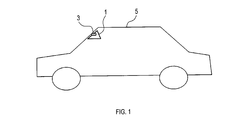
- FIGS. 1 and 2 Configurations of Image Sensor 1 and In-Vehicle Camera 3
- FIGS. 1 and 2 the configurations of the image sensor 1 and the in-vehicle camera 3 will be described based on FIGS. 1 and 2.
- the image sensor 1 is mounted on a vehicle 5.
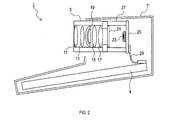
- the image sensor 1 includes an on-vehicle camera 3, a case 7, and a substrate 9.
- the on-vehicle camera 3 includes lenses 11, 13, 15 and 17, a cemented lens 19, a filter 21, an imager 23, a printed circuit board 25, and a camera case 27.
- the lenses 11, 13, 15, 17 and the cemented lens 19 constitute an optical system of the on-vehicle camera 3.
- the configuration of the cemented lens 19 will be described later.
- the filter 21 cuts light in a predetermined wavelength range.
- the imager 23 converts light into electrical signals.
- the printed circuit board 25 holds electronic components including the imager 23.
- the camera case 27 accommodates the components of the on-vehicle camera 3.
- the on-vehicle camera 3 captures the surroundings of the vehicle 5 and creates an image.
- the direction in which the on-vehicle camera 3 shoots is, for example, the front, the rear, the side, etc. of the vehicle 5.
- the case 7 accommodates the on-vehicle camera 3 and the substrate 9.
- the substrate 9 and the printed circuit board 25 are connected by a harness 29.
- the substrate 9 acquires an image created by the on-vehicle camera 3 through the harness 29.
- the substrate 9 analyzes the acquired image and executes a process of driving support.
- the driving support for example, collision avoidance, advanced driving support, lane keep assist, automatic driving and the like can be mentioned.
- the configuration of the junction lens 19 will be described based on FIG.
- the cemented lens 19 includes a convex lens 31, a concave lens 33, and a cemented layer 35.
- the convex lens 31 includes a convex surface 31A.
- the concave lens 33 has a concave surface 33A.
- the convex lens 31 corresponds to the first lens.
- the concave lens 33 corresponds to the second lens.
- the bonding layer 35 bonds the convex surface 31A and the concave surface 33A.
- the bonding layer 35 includes a resin 37 and a gap agent 39.
- the resin 37 is, for example, an active energy ray curable resin. When the resin 37 is an active energy ray curable resin, the process of curing the resin 37 is facilitated. As an active energy ray curable resin, an ultraviolet curable resin etc. are mentioned, for example.
- the resin 37 is, for example, one or more selected from the group consisting of a silicone resin, an acrylic resin, an epoxy resin, and a polyester resin. When the resin 37 is one or more selected from the group consisting of a silicone resin, an acrylic resin, an epoxy resin, and a polyester resin, the clouding of the bonding layer 35 can be further suppressed.
- the gap agent 39 is composed of a plurality of particles.
- the particle size of the particles is, for example, 1 to 30 ⁇ m, preferably 3 to 10 ⁇ m.
- the particle size of the particles is in the range of 1 to 30 ⁇ m, the clouding of the bonding layer 35 can be further suppressed.
- the particle size of the particles is in the range of 3 to 10 ⁇ m, the clouding of the bonding layer 35 can be particularly suppressed.
- the measurement method of the particle size is as follows.
- the gap agent 39 and 5 g of the surfactant are mixed, ultrapure water 30 is further added, and the gap agent is dispersed using an ultrasonic dispersion machine to prepare a measurement sample.
- the average particle size of this measurement sample is measured using a precision particle size distribution measuring device.
- the measured average particle size is taken as the particle size of the gap agent 39.
- the precision particle size distribution measuring device is a Coulter Multisizer manufactured by Beckman Coulter. The diameter of the aperture used is 50 ⁇ m.
- the particles constituting the gap agent 39 are dispersed in the sea of the resin 37.
- the mass of the bonding layer 35 is 100 parts by mass
- the mass of the gap agent 39 is preferably in the range of 0.02 to 0.5 parts by mass. When it is in this range, the clouding of the bonding layer 35 can be further suppressed.
- the gap agent 39 comprises, for example, an organic composition.
- the organic composition include acrylic resin, styrene resin, polyester resin, polyethylene resin, polypropylene resin, polycarbonate resin, silicone resin and the like.
- the refractive index difference the absolute value of the difference between the refractive index of the gap agent 39 and the refractive index of the resin 37 (hereinafter referred to as the refractive index difference) is small. Therefore, scattering of light at the interface between the gap agent 39 and the resin 37 can be suppressed.
- the method of measuring the refractive index of the gap agent 39 and the refractive index of the resin 37 is as follows. 0.5 g of gap agent 39 is added to the high refractive index solvent.
- the high refractive index solvent is carbon disulfide.
- the low refractive index solvent is dropped.
- the low refractive index solvent is ethanol.
- a predetermined amount of low refractive index solvent is dropped, the liquid becomes transparent.
- the composition ratio of the high refractive index solvent to the low refractive index solvent when the liquid becomes transparent is determined.
- the refractive index of a mixed solvent of a high refractive index solvent and a low refractive index solvent having the determined compositional ratio is measured using an Abbe refractometer manufactured by ATAGO. The measurement result is taken as the refractive index of the gap agent 39.
- a plate-like sample having a thickness of 0.1 mm made of resin 37 is prepared.
- the refractive index of this plate-like sample is measured using an Abbe refractometer manufactured by ATAGO.
- the measurement result is taken as the refractive index of the resin 37.
- the light beam used to measure the refractive index is D-line.
- the D line is a light beam having a wavelength of 589 nm.
- the gap agent 39 When the gap agent 39 is made of an organic composition, the gap agent 39 can be prevented from damaging the convex lens 31 or the concave lens 33. In addition, when the gap agent 39 is made of an organic composition, the gap agent 39 does not easily settle in the adhesive described later. Therefore, the content of the gap agent 39 in the bonding layer 35 is stabilized. In addition, the gap agent 39 may be made of an inorganic substance.
- an inorganic substance for example, alumina, aluminum hydroxide, magnesium hydroxide, calcium carbonate, talc, magnesium carbonate, calcium silicate, magnesium silicate, calcium oxide, magnesium oxide, magnesium oxide, aluminum oxide, aluminum nitride, quartz, amorphous silica, Inorganic fillers such as zirconium dioxide, boron nitride, titania, glass, iron oxide and the like can be mentioned.
- Examples of the shape of the particles constituting the gap agent 39 include spherical, amorphous, fibrous, scaly, atypical, and the like.
- the shape of the particles constituting the gap agent 39 is preferably spherical.
- variation in the film thickness of the bonding layer 35 can be reduced.
- grains which comprise the gap agent 39 is spherical shape, when manufacturing the adhesive agent mentioned later, it is hard to entrap air in an adhesive agent.
- the CV in the particle size distribution of the gap agent 39 is preferably 15 or less, and particularly preferably 10 or less. When the CV is 10 or less, the variation in the film thickness of the bonding layer 35 can be reduced.
- CV is a coefficient of variation, also referred to as a coefficient of variation or displacement coefficient.
- CV is a value obtained by dividing the standard deviation of the particle size of the gap agent 39 by the average value of the particle size of the gap agent 39.
- the refractive index difference is preferably 0.01 or less.
- the part of the bonding layer 35 which belongs to the effective optical surface of the cemented lens 19 can be made free of the gap agent 39. In this case, the influence of the gap agent 39 on the optical characteristics of the on-vehicle camera 3 can be suppressed.
- a gap agent 39 can be included in at least a part of the bonding layer 35 which does not belong to the effective optical surface of the cemented lens 19.
- the bonding layer 35 may contain components other than the resin 37 and the gap agent 39.
- junction lens 19 can be manufactured as follows. An adhesive is manufactured by mixing the components including the uncured resin and the gap agent 39. At this time, the gap agent 39 is dispersed in the sea of the uncured resin.
- the adhesive preferably contains an active energy ray polymerization initiator.
- resin 1 or more selected from the group which consists of a silicone resin, an acrylic resin, an epoxy resin, and a polyester resin is mentioned, for example.
- an adhesive is applied to the surface of one or both of the convex surface 31A and the concave surface 33A.
- the convex surface 31A and the concave surface 33A are pasted together by the applied adhesive.
- the adhesive is then cured.
- the adhesive contains an active energy ray curable resin
- the resin is irradiated with active energy rays to cure the resin.
- active energy ray an ultraviolet-ray etc. are mentioned, for example.
- the resin contained in the adhesive is cured to form a resin 37.
- the layer of adhesive becomes the bonding layer 35. Examples of the curing reaction include radical polymerization, cationic polymerization, enethiol reaction, condensation reaction and the like.
- Example (5-1) Example 1 The lens adhesive was added with 0.16 phr of the gap agent and mixed and stirred using a vacuum planetary stirrer.
- the lens adhesive is WR5515 manufactured by Kyoritsu Chemical Industry Co., Ltd.
- the lens adhesive comprises an uncured UV curable resin.
- the ultraviolet curable resin corresponds to an active energy ray curable resin.
- the gap agent is Solli Star RA / B50X manufactured by Nippon Shokubai Co., Ltd.
- the gap agent is composed of a plurality of particles.
- the particle size of the particles is 5 ⁇ m.
- the shape of the particles is spherical.
- the material of the gap agent is an organic / inorganic hybrid material.
- the CV in the particle size distribution of the particles making up the gap agent is 6.2.
- the vacuum planetary stirrer is VRA-210 manufactured by Shinky Co., Ltd.
- the conditions of mixing and stirring are 2000 rpm, 3 minutes, and 3.0 kPa.
- a gap agent-containing adhesive was obtained.
- the gap agent was uniformly dispersed.
- a convex lens and a concave lens were prepared.
- a gap agent-containing adhesive was dropped on the concave surface of the concave lens.
- the concave surface of the concave lens and the convex surface of the convex lens were attached to each other by the dropped gap agent-containing adhesive.
- a layer of cured gap agent adhesive constitutes a cemented layer.
- the bonding layer contains a resin and a gap agent.
- the absolute value of the difference between the refractive index of the gap agent and the refractive index of the resin was 0.002.
- the maximum value in the film thickness of the bonding layer was 12.8 ⁇ m, and the minimum value was 5.7 ⁇ m.
- Example 2 A cemented lens was manufactured basically in the same manner as in Example 1. However, in this example, WR5517 manufactured by Kyoritsu Chemical Industry Co., Ltd. was used as a lens adhesive instead of WR5515. The WR 5517 contains an uncured ultraviolet curable resin.
- the absolute value of the difference between the refractive index of the gap agent and the refractive index of the resin contained in the bonding layer was 0.010.
- the maximum value of the film thickness of the bonding layer was 13.5 ⁇ m, and the minimum value was 6.2 ⁇ m.
- the materials used to manufacture the cemented lens, the configuration of the adhesive layer, and the like are shown in Table 1 above.
- Example 3 A cemented lens was manufactured basically in the same manner as in Example 1. However, in the present example, Solly Star RA / E48X manufactured by Nippon Shokubai Co., Ltd. was used as the gap agent instead of Solly Star RA / B50X.
- the sory star RA / E 48X is composed of a plurality of particles. The particle size of the particles is 4.8 ⁇ m. The shape of the particles is spherical.
- the material of the SOLY STAR RA / E 48X is an organic-inorganic hybrid material.
- the CV in the particle size distribution of the particles making up the Soli Star RA / E 48X is 6.5.
- the absolute value of the difference between the refractive index of the gap agent and the refractive index of the resin contained in the bonding layer was 0.032.
- the maximum value of the film thickness of the bonding layer was 12.3 ⁇ m, and the minimum value was 5.4 ⁇ m.
- the materials used to manufacture the cemented lens, the configuration of the adhesive layer, and the like are shown in Table 1 above.
- ⁇ The increase in error is less than 10%.
- ⁇ The increase in error is 10% or more and less than 20%.
- Fair increase in error is 20% or more.
- Example 1 and 2 the evaluation results of the initial optical characteristics were good. The reason is presumed to be that the difference in refractive index is small in Examples 1 and 2. (5-7) Occurrence Test of White Cloudiness
- the cemented lenses of Examples 1 to 3 and Comparative Examples 1 and 2 were tested as follows to determine whether white turbidity occurs in the bonding layer when thermal shock is applied.
- the cemented lens was housed in a thermal shock tester. Maintaining at a temperature of 120 ° C. for 30 minutes, and then maintaining at a temperature of ⁇ 40 ° C. for 30 minutes was one cycle. This cycle was repeated 2000 times. Thereafter, the outer peripheral side of the bonding layer was observed with a microscope, and it was judged whether or not white turbidity occurred.
- Examples 1 to 3 contains the gap agent, the film thickness of the bonding layer is larger than in Comparative Examples 1 and 2 in which the gap agent is not contained, and the film thickness is stabilized. As a result, even if thermal strain occurs in the bonding layer, the stress applied to the resin is reduced and it becomes difficult to cause white turbidity.
- the cemented lens 19 may be used for cameras other than the on-vehicle camera 3 or the like.
- the first lens 31 having the convex surface 31A may be a lens other than a convex lens.
- the second lens 33 having the concave surface 33A may be a lens other than the concave lens.
- the plurality of functions of one component in the above embodiment may be realized by a plurality of components, or one function of one component may be realized by a plurality of components . Also, a plurality of functions possessed by a plurality of components may be realized by one component, or one function realized by a plurality of components may be realized by one component.
- part of the configuration of the above embodiment may be omitted.
- at least a part of the configuration of the above embodiment may be added to or replaced with the configuration of the other above embodiment.
- all the aspects contained in the technical thought specified from the wording described in the claim are an embodiment of this indication.
Landscapes
- Physics & Mathematics (AREA)
- General Physics & Mathematics (AREA)
- Optics & Photonics (AREA)
- Engineering & Computer Science (AREA)
- Multimedia (AREA)
- Signal Processing (AREA)
- Lens Barrels (AREA)
- Surface Treatment Of Optical Elements (AREA)
Priority Applications (3)
| Application Number | Priority Date | Filing Date | Title |
|---|---|---|---|
| CN201880044034.7A CN110832359A (zh) | 2017-06-30 | 2018-06-26 | 接合透镜以及车载相机 |
| DE112018003369.4T DE112018003369T5 (de) | 2017-06-30 | 2018-06-26 | Verkittete Linse und Fahrzeug-Kamera |
| US16/709,139 US20200124826A1 (en) | 2017-06-30 | 2019-12-10 | Cemented lens and in-vehicle camera |
Applications Claiming Priority (2)
| Application Number | Priority Date | Filing Date | Title |
|---|---|---|---|
| JP2017-128873 | 2017-06-30 | ||
| JP2017128873A JP2019012196A (ja) | 2017-06-30 | 2017-06-30 | 接合レンズ及び車載カメラ |
Related Child Applications (1)
| Application Number | Title | Priority Date | Filing Date |
|---|---|---|---|
| US16/709,139 Continuation US20200124826A1 (en) | 2017-06-30 | 2019-12-10 | Cemented lens and in-vehicle camera |
Publications (1)
| Publication Number | Publication Date |
|---|---|
| WO2019004196A1 true WO2019004196A1 (ja) | 2019-01-03 |
Family
ID=64741721
Family Applications (1)
| Application Number | Title | Priority Date | Filing Date |
|---|---|---|---|
| PCT/JP2018/024165 WO2019004196A1 (ja) | 2017-06-30 | 2018-06-26 | 接合レンズ及び車載カメラ |
Country Status (5)
Families Citing this family (3)
| Publication number | Priority date | Publication date | Assignee | Title |
|---|---|---|---|---|
| TWI670516B (zh) * | 2018-06-13 | 2019-09-01 | 大立光電股份有限公司 | 攝影光學鏡頭、取像裝置及電子裝置 |
| US20220204813A1 (en) | 2019-01-28 | 2022-06-30 | Nitto Denko Corporation | Adhesive skin patch material |
| JP7683283B2 (ja) | 2021-03-31 | 2025-05-27 | セイコーエプソン株式会社 | 光学素子、投射光学装置及びプロジェクター |
Citations (4)
| Publication number | Priority date | Publication date | Assignee | Title |
|---|---|---|---|---|
| JP2003139913A (ja) * | 2001-11-01 | 2003-05-14 | Pentax Corp | 貼合レンズ |
| JP2003139914A (ja) * | 2001-11-01 | 2003-05-14 | Pentax Corp | 貼合レンズ |
| JP2008176183A (ja) * | 2007-01-22 | 2008-07-31 | Fujinon Corp | 撮像レンズ、および該撮像レンズを備えた撮像装置 |
| JP2015176735A (ja) * | 2014-03-14 | 2015-10-05 | 凸版印刷株式会社 | El素子、照明装置、ディスプレイ装置、および液晶ディスプレイ装置 |
Family Cites Families (5)
| Publication number | Priority date | Publication date | Assignee | Title |
|---|---|---|---|---|
| JP3826720B2 (ja) * | 2000-04-25 | 2006-09-27 | セイコーエプソン株式会社 | マイクロレンズ基板の製造方法およびマイクロレンズ基板 |
| US9030108B2 (en) * | 2012-05-07 | 2015-05-12 | David Deak, SR. | Gaussian surface lens quantum photon converter and methods of controlling LED colour and intensity |
| CN106105389B (zh) * | 2014-03-14 | 2018-08-10 | 凸版印刷株式会社 | El元件、el元件用基板、照明装置、显示器装置及液晶显示器装置 |
| JP6177747B2 (ja) * | 2014-09-18 | 2017-08-09 | 富士フイルム株式会社 | 撮像レンズおよび撮像装置 |
| US9945987B2 (en) * | 2014-10-07 | 2018-04-17 | Sharp Kabushiki Kaisha | Transparent film, and method for producing transparent film |
-
2017
- 2017-06-30 JP JP2017128873A patent/JP2019012196A/ja active Pending
-
2018
- 2018-06-26 DE DE112018003369.4T patent/DE112018003369T5/de not_active Ceased
- 2018-06-26 WO PCT/JP2018/024165 patent/WO2019004196A1/ja active Application Filing
- 2018-06-26 CN CN201880044034.7A patent/CN110832359A/zh active Pending
-
2019
- 2019-12-10 US US16/709,139 patent/US20200124826A1/en not_active Abandoned
Patent Citations (4)
| Publication number | Priority date | Publication date | Assignee | Title |
|---|---|---|---|---|
| JP2003139913A (ja) * | 2001-11-01 | 2003-05-14 | Pentax Corp | 貼合レンズ |
| JP2003139914A (ja) * | 2001-11-01 | 2003-05-14 | Pentax Corp | 貼合レンズ |
| JP2008176183A (ja) * | 2007-01-22 | 2008-07-31 | Fujinon Corp | 撮像レンズ、および該撮像レンズを備えた撮像装置 |
| JP2015176735A (ja) * | 2014-03-14 | 2015-10-05 | 凸版印刷株式会社 | El素子、照明装置、ディスプレイ装置、および液晶ディスプレイ装置 |
Also Published As
| Publication number | Publication date |
|---|---|
| DE112018003369T5 (de) | 2020-03-12 |
| US20200124826A1 (en) | 2020-04-23 |
| JP2019012196A (ja) | 2019-01-24 |
| CN110832359A (zh) | 2020-02-21 |
Similar Documents
| Publication | Publication Date | Title |
|---|---|---|
| JP6197647B2 (ja) | 光学フィルタとその製造方法、並びに撮像装置 | |
| US10808150B2 (en) | Resin composition, method for manufacturing semiconductor device using resin composition, and solid-state imaging element | |
| JP4022246B1 (ja) | 撮像レンズ | |
| TWI401287B (zh) | 無機氧化物透明分散液及含無機氧化物粒子的樹脂組成物、發光元件封裝用組成物及發光元件、硬塗膜與光學機能膜及光學組件,以及含無機氧化物粒子之樹脂組成物的製造方法 | |
| US20200124826A1 (en) | Cemented lens and in-vehicle camera | |
| US9868884B2 (en) | Adhesive composition, method for manufacturing semiconductor device using adhesive composition, and solid-state imaging element | |
| WO2008075469A1 (ja) | 撮像レンズ | |
| WO2008068909A1 (ja) | 撮像レンズ | |
| WO2012086350A1 (ja) | レンズユニット及び撮像ユニット | |
| CN109716172A (zh) | 高折射率纳米复合物 | |
| KR20130041344A (ko) | 광확산 소자 및 광확산 소자를 가진 편광판 | |
| US11976179B2 (en) | Particle material and manufacturing method therefor, and transparent resin composition | |
| WO2017170689A1 (ja) | 光ファイバアレイ | |
| JP2007122016A (ja) | 光学材料及び光学素子 | |
| US11914180B2 (en) | Optical filter, method of producing same, and optical module | |
| KR102022142B1 (ko) | 글레어의 정량적 평가 방법 | |
| JP2011164284A (ja) | 光学素子ユニット | |
| US7702206B2 (en) | Optical waveguide and method for manufacturing the same | |
| JP2009221350A (ja) | 樹脂組成物、その製造方法、及びそれを用いた光学素子 | |
| CN114573849A (zh) | 光学薄膜的制造方法、光学薄膜、光学构件、图像显示装置、及它们的制造方法 | |
| WO2019082417A1 (ja) | 光学素子、光学系、光学装置、及び、光学素子の製造方法 | |
| JP2007191687A (ja) | 有機無機複合体形成用材料、有機無機複合体、その製造方法及び光学素子 | |
| EP4266089A1 (en) | Article including porous layer containing inorganic particles, and coating liquid for forming porous layer containing inorganic particles | |
| JP4319301B2 (ja) | ロッドレンズアレイおよびその製造方法 | |
| US9376553B2 (en) | Organic-inorganic composite molded product and optical element |
Legal Events
| Date | Code | Title | Description |
|---|---|---|---|
| 121 | Ep: the epo has been informed by wipo that ep was designated in this application |
Ref document number: 18824110 Country of ref document: EP Kind code of ref document: A1 |
|
| 122 | Ep: pct application non-entry in european phase |
Ref document number: 18824110 Country of ref document: EP Kind code of ref document: A1 |