WO2019004087A1 - シリンダ装置のシール状態検出方法およびシール状態検出装置 - Google Patents
シリンダ装置のシール状態検出方法およびシール状態検出装置 Download PDFInfo
- Publication number
- WO2019004087A1 WO2019004087A1 PCT/JP2018/023843 JP2018023843W WO2019004087A1 WO 2019004087 A1 WO2019004087 A1 WO 2019004087A1 JP 2018023843 W JP2018023843 W JP 2018023843W WO 2019004087 A1 WO2019004087 A1 WO 2019004087A1
- Authority
- WO
- WIPO (PCT)
- Prior art keywords
- cylinder
- chamber
- pressure
- cylinder device
- state
- Prior art date
- Legal status (The legal status is an assumption and is not a legal conclusion. Google has not performed a legal analysis and makes no representation as to the accuracy of the status listed.)
- Ceased
Links
Images
Classifications
-
- F—MECHANICAL ENGINEERING; LIGHTING; HEATING; WEAPONS; BLASTING
- F16—ENGINEERING ELEMENTS AND UNITS; GENERAL MEASURES FOR PRODUCING AND MAINTAINING EFFECTIVE FUNCTIONING OF MACHINES OR INSTALLATIONS; THERMAL INSULATION IN GENERAL
- F16F—SPRINGS; SHOCK-ABSORBERS; MEANS FOR DAMPING VIBRATION
- F16F9/00—Springs, vibration-dampers, shock-absorbers, or similarly-constructed movement-dampers using a fluid or the equivalent as damping medium
- F16F9/32—Details
- F16F9/36—Special sealings, including sealings or guides for piston-rods
-
- F—MECHANICAL ENGINEERING; LIGHTING; HEATING; WEAPONS; BLASTING
- F16—ENGINEERING ELEMENTS AND UNITS; GENERAL MEASURES FOR PRODUCING AND MAINTAINING EFFECTIVE FUNCTIONING OF MACHINES OR INSTALLATIONS; THERMAL INSULATION IN GENERAL
- F16J—PISTONS; CYLINDERS; SEALINGS
- F16J15/00—Sealings
-
- G—PHYSICS
- G01—MEASURING; TESTING
- G01M—TESTING STATIC OR DYNAMIC BALANCE OF MACHINES OR STRUCTURES; TESTING OF STRUCTURES OR APPARATUS, NOT OTHERWISE PROVIDED FOR
- G01M3/00—Investigating fluid-tightness of structures
- G01M3/02—Investigating fluid-tightness of structures by using fluid or vacuum
- G01M3/04—Investigating fluid-tightness of structures by using fluid or vacuum by detecting the presence of fluid at the leakage point
- G01M3/20—Investigating fluid-tightness of structures by using fluid or vacuum by detecting the presence of fluid at the leakage point using special tracer materials, e.g. dye, fluorescent material, radioactive material
-
- G—PHYSICS
- G01—MEASURING; TESTING
- G01M—TESTING STATIC OR DYNAMIC BALANCE OF MACHINES OR STRUCTURES; TESTING OF STRUCTURES OR APPARATUS, NOT OTHERWISE PROVIDED FOR
- G01M3/00—Investigating fluid-tightness of structures
- G01M3/02—Investigating fluid-tightness of structures by using fluid or vacuum
- G01M3/26—Investigating fluid-tightness of structures by using fluid or vacuum by measuring rate of loss or gain of fluid, e.g. by pressure-responsive devices, by flow detectors
Definitions
- the present invention relates to a seal state detection method and a seal state detection device for a cylinder device.
- Priority is claimed on Japanese Patent Application No. 2017-126271, filed Jun. 28, 2017, the content of which is incorporated herein by reference.
- the present invention provides a seal state detection method and a seal state detection device of a cylinder device that can suppress an increase in cost.
- a method of detecting a sealing state of a cylinder device includes an accommodating step of accommodating the entire cylinder device in a sealable chamber, and a reduced pressure in which the inside of the chamber is reduced by a predetermined pressure than atmospheric pressure. It includes a pressure reduction process to make a state, a pressure measurement process to measure the pressure in the chamber, and an abnormality detection process to detect an abnormality based on the pressure in the chamber.
- a method of detecting a sealing state of a cylinder device comprising: an accommodating step of accommodating the entire cylinder device in a sealable chamber; It includes a pressure reduction step to make the state, a nitrogen gas amount measurement step of measuring the amount of nitrogen gas in the chamber, and an abnormality detection step of detecting an abnormality based on the amount of nitrogen gas in the chamber.
- the seal state detection device of the cylinder device includes a sealable chamber for accommodating the entire cylinder device, and a pressure reduction state in which the inside of the chamber is reduced by a predetermined pressure lower than atmospheric pressure.
- abnormality detection means for detecting an abnormality based on the
- the seal state detection device of the cylinder device includes a sealable chamber for accommodating the entire cylinder device, and a pressure reduction state in which the inside of the chamber is reduced by a predetermined pressure lower than atmospheric pressure.
- Means a nitrogen gas amount measuring means for measuring the amount of nitrogen gas in the chamber, and the entire amount of nitrogen gas in the chamber enclosed and sealed by the pressure reducing means by accommodating the whole of the cylinder device
- abnormality detection means for detecting an abnormality based on the measurement result by the nitrogen gas amount measurement means.
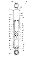
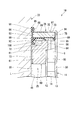
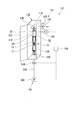
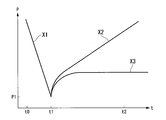
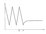
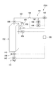
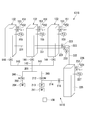
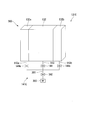
- 1 is a cross-sectional view showing a cylinder state to be inspected of a seal state detection method and a seal state detection device according to an embodiment of the present invention. It is an expanded sectional view of an important section showing the cylinder state used as the inspection object of the seal state detection method concerning the embodiment of the present invention, and a seal state detection device. It is a block diagram showing the seal state detection device concerning a 1st embodiment of the present invention. It is a diagram which shows the pressure state in the chamber in the pressure reduction process and pressure measurement process which concern on 1st Embodiment of this invention. It is a diagram which shows the pressure state in the chamber in the drying process, pressure reduction process, and pressure measurement process which concern on 1st Embodiment of this invention.
- a sealing state detection method and a cylinder device to be inspected of the sealing state detection device according to an embodiment of the present invention will be described below with reference to FIGS. 1 and 2.
- the cylinder device 10 is used for a suspension device of a car or a railway vehicle. As shown in FIG. 1, the cylinder device 10 has a cylinder 11 in which a working fluid is sealed.
- the cylinder 11 is a double cylinder type comprised of an inner cylinder 12 and an outer cylinder 13 having a diameter larger than that of the inner cylinder 12 and provided outside the inner cylinder 12.
- the inner cylinder 12 and the outer cylinder 13 are coaxially arranged.
- a reservoir chamber 14 is formed between the inner cylinder 12 and the outer cylinder 13.
- a piston 17 is slidably inserted into the inner cylinder 12 of the cylinder 11.
- the piston 17 defines an upper chamber 18 and a lower chamber 19 in the inner cylinder 12, that is, in the cylinder 11.
- the hydraulic fluid L as a fluid is enclosed in the upper chamber 18 and the lower chamber 19, and the hydraulic fluid L and the gas G as a fluid are enclosed in the reservoir chamber 14.
- the gas G is specifically nitrogen gas.
- a piston rod 22 is connected to the piston 17.
- the piston rod 22 has a first axial side inserted into the cylinder 11 and connected to the piston 17, and a second axial side is an axial direction of the cylinder 11 (vertical direction in FIG. 1, hereinafter referred to as cylinder axial direction)
- cylinder axial direction One end, that is, one end of the inner cylinder 12 and the outer cylinder 13 extends to the outside.
- the piston 17 is fastened to an end of the piston rod 22 in the inner cylinder 12 by a nut 23 and moves integrally with the piston 17.
- annular rod guide 25 and an annular seal member 26 are coaxially disposed on one end side in the cylinder axial direction from which the piston rod 22 protrudes.
- the seal member 26 is provided outside (upper and lower direction upper side in FIG. 1) than the rod guide 25 in the inner and outer direction (vertical direction in FIG. 1; hereinafter referred to as cylinder inner and outer direction in FIG. 1) in the cylinder axial direction.
- the rod guide 25 is provided on the inner side (upper and lower direction in FIG. 1) of the seal member 26 in the cylinder inner and outer direction.
- a base valve 28 is provided on the side opposite to the rod guide 25 and the seal member 26 in the cylinder axial direction.
- the rod guide 25 and the seal member 26 have the piston rod 22 slidably inserted therein.
- the piston rod 22 is disposed on the central axis of the cylinder 11 by a piston 17 disposed in the inner cylinder 12 at one end portion disposed in the cylinder 11. Further, the piston rod 22 is disposed on the central axis of the cylinder 11 by a rod guide 25 in which an axial intermediate portion is fitted to the cylinder 11.
- the rod guide 25 axially movably supports the piston rod 22 while restricting its radial movement.
- the outer periphery of the seal member 26 is closely fitted to the inside of the outer cylinder 13 of the cylinder 11.
- the seal member 26 is inserted such that the piston rod 22 is in close contact with the inner peripheral portion thereof. Thereby, the seal member 26 closes one end side of the cylinder 11 and regulates the leakage of the hydraulic fluid L in the inner cylinder 12 and the gas G and hydraulic fluid L in the reservoir chamber 14 to the outside.
- the outer cylinder 13 of the cylinder 11 has a substantially bottomed cylindrical shape having a cylindrical body portion 30, a bottom portion 31 and a locking portion 33.
- the bottom 31 closes the end of the body 30 opposite to the projecting side of the piston rod 22.
- the locking portion 33 protrudes radially inward from the position of the opening 32 on the protruding side of the piston rod 22 in the body 30.
- the inner cylinder 12 of the cylinder 11 has a cylindrical shape.
- the first end of the inner cylinder 12 in the axial direction is supported in a fitted state by the base body 34 of the base valve 28 disposed inside the bottom 31 of the outer cylinder 13.
- the second end side in the axial direction of the inner cylinder 12 is supported in a fitted state by a rod guide 25 fitted inside the opening 32 of the outer cylinder 13.
- the base body 34 of the base valve 28 is formed with a fluid passage 36 and a fluid passage 37 penetrating in the axial direction.
- the fluid passage 36 and the fluid passage 37 can communicate the lower chamber 19 in the inner cylinder 12 with the reservoir chamber 14 between the outer cylinder 13 and the inner cylinder 12.
- a disc valve 38 is disposed on the bottom 31 side, and a disc valve 39 is disposed on the opposite side of the bottom 31.
- the disc valve 38 is capable of opening and closing the inner fluid passage 36 in the radial direction of the base body 34.
- the disc valve 39 can open and close the fluid passage 37 outside the fluid passage 36 in the radial direction of the base body 34.
- the disc valves 38 and 39 are attached to the base body 34 by rivets 42 inserted into the center of the base body 34 and crimped.
- the disc valve 38 allows the flow of the hydraulic fluid L from the lower chamber 19 to the reservoir chamber 14 side through a passage hole and a liquid passage 36 (not shown) formed in the disc valve 39.
- the disc valve 38 controls the flow of the hydraulic fluid L to generate a damping force.
- the disc valve 38 regulates the flow of the hydraulic fluid L in the opposite direction. That is, the disc valve 38 moves to the contraction side where the piston rod 22 reduces the amount of protrusion from the cylinder 11, and the piston 17 moves to the lower chamber 19 side to open the liquid passage 36 when the pressure in the lower chamber 19 increases. At that time, it is a damping valve that generates damping force.
- the disc valve 39 allows the flow of the hydraulic fluid L from the reservoir chamber 14 to the lower chamber 19 side without resistance via the fluid passage 37.
- the disc valve 39 regulates the flow of the hydraulic fluid L in the opposite direction.
- the disc valve 39 moves to the extension side where the piston rod 22 increases the amount of protrusion from the cylinder 11, and the piston 17 moves to the upper chamber 18 side and the fluid passage 37 opens when the pressure in the lower chamber 19 drops.
- the disc valve 39 is a suction valve that allows the hydraulic fluid L to flow from the reservoir chamber 14 into the lower chamber 19 substantially without generating a damping force.
- the piston rod 22 has a main shaft 45 of a fixed diameter, and an inner end shaft 46 at an end to be inserted into the inner cylinder 12.
- the inner end shaft portion 46 is smaller in diameter than the main shaft portion 45, and an external thread 47 is formed on the opposite side of the main shaft portion 45.
- the nut 23 is screwed into the male screw 47.
- the piston 17 and the disc valves 51 and 52 on both sides thereof are attached to the piston rod 22 by the nut 23.
- the piston 17 is formed with a through hole 53 axially penetrating at the center in the radial direction.
- a fluid passage 54 and a fluid passage 55 which penetrate in the axial direction are formed around the through hole 53.
- the inner end shaft portion 46 of the piston rod 22 is inserted into the through hole 53.
- the fluid passage 54 and the fluid passage 55 can communicate the lower chamber 19 on the bottom 31 side with respect to the piston 17 in the inner cylinder 12 and the upper chamber 18 on the opposite side of the bottom 31 with respect to the piston 17 in the inner cylinder 12 It has become.
- the disc valve 51 is disposed on the opposite side to the bottom 31, and the disc valve 52 is disposed on the bottom 31 side.
- the disk valve 51 is a damping valve capable of opening and closing the fluid passage 54.
- the disk valve 52 is a damping valve capable of opening and closing the fluid passage 55.
- the disc valve 51 allows the flow of the hydraulic fluid L from the lower chamber 19 to the upper chamber 18, while restricting the flow of the hydraulic fluid L in the reverse direction.
- the disc valve 51 opens the liquid passage 54 and generates a damping force at that time. That is, the disc valve 51 is a compression side damping valve.
- the disc valve 52 allows the flow of the hydraulic fluid L from the upper chamber 18 side to the lower chamber 19 while restricting the flow of the hydraulic fluid L in the opposite direction.
- the disc valve 52 opens the liquid passage 55 and generates a damping force at that time. That is, the disc valve 52 is an expansion side damping valve.
- the rod guide 25 includes a rod guide main body 60 having a substantially stepped annular shape, and a cylindrical collar 61 fitted and fixed to the inner peripheral portion of the rod guide main body 60.
- a large diameter outer peripheral portion 64 having a circular shape is formed on the outer side in the inner and outer direction of the cylinder, and a small diameter outer peripheral portion 65 having a smaller diameter than the large outer peripheral portion 64 is formed on the inner side It has a different shape.
- the large diameter outer peripheral portion 64 and the small diameter outer peripheral portion 65 are formed coaxially.
- the large diameter outer peripheral portion 64 of the rod guide main body 60 is fitted to the inner peripheral portion of the body portion 30 of the outer cylinder 13 of the cylinder 11.
- the small diameter outer peripheral portion 65 of the rod guide main body 60 is fitted to the inner peripheral portion of the inner cylinder 12 of the cylinder 11.
- the large diameter inner peripheral portion 72 having a circular shape is provided on the outer side in the cylinder inner and outer direction, and the small diameter small inner peripheral portion 73 having a smaller diameter than the large diameter inner peripheral portion 72 is provided on the inner side. It has a formed shape.
- annular annular convex portion 75 On the outer side of the rod guide main body 60 in the cylinder inward and outward direction, an annular annular convex portion 75 is formed which protrudes outward in the cylinder inward and outward direction.
- the annular convex portion 75 is coaxially arranged with the large diameter outer peripheral portion 64, the small diameter outer peripheral portion 65, the large diameter inner peripheral portion 72 and the small diameter inner peripheral portion 73.
- the outer peripheral portion of the annular convex portion 75 has a tapered shape in which the diameter decreases toward the tip end of the protrusion.
- the inner circumferential portion of the annular convex portion 75 is tapered such that the diameter increases toward the tip end of the protrusion.
- a communication hole 81 penetrating along the axial direction is formed at the radially inner position of the annular convex portion 75.
- the communication hole 81 communicates with the reservoir chamber 14 between the outer cylinder 13 and the inner cylinder 12.
- the collar 61 is fitted and fixed in the small diameter inner peripheral portion 73 of the rod guide main body 60. In the collar 61, the main shaft 45 of the piston rod 22 is inserted in a sliding contact.
- the outer peripheral portion of the seal member 26 contacts the inner peripheral portion of the outer cylinder 13 to seal a gap with the outer cylinder 13. Further, the seal member 26 contacts the outer peripheral portion of the main shaft 45 of the piston rod 22 so that the seal member 26 seals a gap with the outer peripheral portion of the main shaft 45. Thus, the seal member 26 is provided between the outer cylinder 13 of the cylinder 11 and the main shaft 45 of the piston rod 22 to close the space therebetween.
- the seal member 26 is an integrally molded article in which the annular member 86 is embedded in the elastic member 85.
- the elastic member 85 is made of a slidable rubber material such as nitrile rubber or fluorine rubber. A portion of the elastic member 85 in contact with the annular member 86 is entirely bonded to the annular member 86.
- the annular member 86 is made of metal and has an annular shape. The annular member 86 maintains the shape of the seal member 26. The annular member 86 causes the seal member 26 to have strength for fixing to the target site.
- the elastic member 85 includes an annular seal ring 89, an annular check lip 90, an annular dust lip 91, an annular oil lip 92, an annular inner circumferential covering portion 93, an annular outer circumferential seal 94, and an annular outer ring 94 And an annular outer end surface covering portion 96.
- the dust lip 91 extends from the inner circumferential side of the annular member 86 to the outside in the cylinder inward and outward direction in an annular cylindrical shape.
- the dust lip 91 has a smaller diameter as the inner peripheral portion thereof is positioned on the outer side in the cylinder inner and outer direction.
- the oil lip 92 extends from the inner circumferential side of the annular member 86 to the inside in the inner and outer direction of the cylinder in an annular cylindrical shape.
- the oil lip 92 has a smaller diameter as the inner peripheral portion thereof is positioned inward in the inward and outward direction of the cylinder.
- the inner circumferential covering portion 93 has a cylindrical shape. The inner circumferential covering portion 93 connects the proximal end side of the dust lip 91 and the proximal end side of the oil lip 92 while covering the inner circumferential surface of the annular member 86.
- the outer circumferential seal 94 has a cylindrical shape.
- the outer circumferential seal 94 covers the outer circumferential surface of the annular member 86.
- the inner end surface covering portion 95 connects the base end side of the oil lip 92 and the outer peripheral seal 94, and covers the entire inner end surface of the annular member 86 in the inner and outer direction of the cylinder.
- the outer end surface covering portion 96 extends in the radial direction from the proximal end side of the dust lip 91, and partially covers the inner diameter side of the end surface of the annular member 86 at the outer side in the cylinder inner and outer direction.
- the annular member 86 has an exposed portion 97 which is not covered by the elastic member 85 between the outer end surface covering portion 96 and the outer peripheral seal 94.
- the seal ring 89 has an annular shape.
- the seal ring 89 protrudes from the outer peripheral edge of the inner end surface covering portion 95 inward in the cylinder inward and outward direction.
- the check lip 90 has an annular shape.
- the check lip 90 protrudes from the radial intermediate portion of the inner end surface covering portion 95 to the inside in the inner and outer direction of the cylinder while expanding in diameter.
- An annular metal spring 98 is mounted on an outer peripheral portion of the dust lip 91.
- An annular metal spring 99 is mounted on the outer periphery of the oil lip 92.
- the main shaft 45 of the piston rod 22 is inserted through the sealing member 26 into the inside of the dust lip 91, the inner circumferential covering portion 93 and the oil lip 92.
- the dust lip 91 and the oil lip 92 are in close contact with the main shaft 45 of the piston rod 22 over the entire circumference.
- the seal member 26 When the seal member 26 is attached to the cylinder 11, the seal member 26 is inserted into the trunk 30 of the outer cylinder 13 from the opening 32 side before forming the locking portion 33 on the opening 32 side of the outer cylinder 13. , And abut on the annular convex portion 75 of the rod guide 25. In this state, the opening portion 32 side of the trunk portion 30 is bent inward in the radial direction to form the locking portion 33, whereby the locking portion 33 abuts on the exposed portion 97 of the annular member 86 of the sealing member 26. The annular member 86 and the inner end surface covering portion 95 are sandwiched by the annular convex portion 75. Thus, the seal member 26 is attached to the cylinder 11.
- the outer peripheral seal 94 of the seal member 26 attached to the cylinder 11 is in contact with the inner peripheral portion of the outer cylinder 13 of the cylinder 11, and the seal ring 89 is the outer peripheral portion of the annular convex portion 75 of the rod guide 25. , And the inner peripheral portion of the outer cylinder 13. Thereby, the seal member 26 is in close contact with the inner peripheral portion of the outer cylinder 13 over the entire circumference to seal the space between the outer cylinder 13 and the outer cylinder 13.
- the main shaft 45 of the piston rod 22 is inserted into the inside of the dust lip 91, the inner circumferential covering portion 93 and the oil lip 92 in the seal member 26 in a state of being attached to the cylinder 11.
- one end of the piston rod 22 protrudes from the seal member 26 to the outside.
- the dust lip 91 and the oil lip 92 are in close contact with the outer periphery of the main shaft 45 of the piston rod 22 so as to seal between the main shaft 45 and the entire periphery.
- the seal member 26 is provided between the cylinder 11 and the piston rod 22 to seal between them.
- the seal member 26 in the state of being attached to the cylinder 11 enables the check lip 90 to make sealing contact over the entire circumference with a predetermined interference at a portion radially inward of the annular convex portion 75 of the rod guide 25 There is.
- the hydraulic fluid L leaked out from the gap between the rod guide 25 and the piston rod 22 is collected in the chamber 100 on the gap side with respect to the check lip 90.
- the check lip 90 is opened when the pressure in the chamber 100 is higher than the pressure in the reservoir chamber 14 and the hydraulic fluid L accumulated in the chamber 100 flows to the reservoir chamber 14 through the communication hole 81. That is, the check lip 90 functions as a check valve which permits the flow of the working fluid L and the gas G only in the direction from the chamber 100 to the reservoir chamber 14 and restricts the flow in the reverse direction.
- a retainer 111 is fixed to the main shaft 45 of the piston rod 22 so as to expand radially outward on the side of the inner end shaft 46 with respect to the insertion portion into the rod guide 25.
- a buffer body 112 made of an annular elastic material is provided with the main shaft 45 inserted inside.
- a cover member 115 is attached to one end of the piston rod 22 opposite to the cylinder 11.
- the cover member 115 has a disc-shaped lid portion 118 and a cylindrical portion 119.
- the lid portion 118 is fixed to the piston rod 22 and spreads radially from the piston rod 22.
- the cylindrical portion 119 extends in the direction of the cylinder 11 from the outer peripheral edge portion of the lid portion 118.
- the cylindrical portion 119 extends from the opening 32 of the cylinder 11 to the bottom 31 side.
- the cylindrical portion 119 covers the outer peripheral portion of the cylinder 11 with a gap in the radial direction between the cylindrical portion 119 and the outer peripheral portion.
- a mounting eye 116 is fixed to the side opposite to the piston rod 22 and the bottom 31 of the lid 118.
- a guard member 121 is attached to the outer peripheral surface on the bottom 31 side of the body 30 of the cylinder 11, and the mounting eye 122 is fixed to the bottom 31 opposite to the piston rod 22.
- the mounting eye 116 is disposed on the upper side and connected to the vehicle body side, and the mounting eye 122 is disposed on the lower side and connected to the wheel side.
- the pressures in the upper chamber 18, the lower chamber 19 and the reservoir chamber 14 are substantially equal, and all are higher than the atmospheric pressure.
- the pressures of the hydraulic fluid L and the gas G in the cylinder 11 are both higher than the atmospheric pressure.
- the piston 17 and the piston rod 22 stop at a predetermined position with respect to the cylinder 11.
- the length of the cylinder device 10 at this time is a natural length.
- the embodiment is a seal state detection method and a seal state detection device for detecting an abnormality in the seal state of the seal member 26 in the cylinder device 10 described above.
- the seal state detection device 131 has a chamber 132 sized and capable of sealing the entire cylinder device 10 therein.
- the chamber 132 has a chamber body 136 having an opening 135 and a door 137 connected to the chamber body 136 for opening and closing the opening 135.
- the chamber body 136 has a hook 138 attached to the ceiling portion.
- the cylinder device 10 is taken in and out from the opening 135 with the door 137 opened.
- the hook 138 is inserted into the inside of the mounting eye 116 of the cylinder device 10 inserted into the chamber body 136 through the opening 135.
- the cylinder device 10 is suspended by the hook 138.
- the cylinder device 10 in a state of being locked to the hook 138 by the mounting eye 116 and suspended by the hook 138 is in a state of natural length, and is in a state of being vertically aligned with the seal member 26 upward by its own weight.
- the chamber 132 hermetically seals the inside when the door 137 is closed.
- the cylinder device 10 is described as being suspended, but the cylinder device 10 may not be suspended as long as the sealing member 26 is installed upward.
- the sealed state detection device 131 has a pressure reducing unit 141 (pressure reducing means) that brings the inside of the chamber 132 in the sealed state into a check pressure reducing state (pressure reducing state) reduced by a predetermined pressure than atmospheric pressure.
- the decompression unit 141 is provided in the communication passage 143 connecting the vacuum pump 142 and the chamber 132 by connecting the vacuum pump 142 and the chamber 132, and the communication passage 143 is opened and closed by opening and closing the vacuum pump 142 and the chamber 132. It has the on-off valve 144 which switches communication and interruption
- the vacuum pump 142 evacuates the inside of the chamber 132 in a closed state with the open / close valve 144 open.
- the on-off valve 144 When the on-off valve 144 is closed, the communication between the chamber 132 and the vacuum pump 142 is shut off, and the inside of the chamber 132 is maintained at the above-described inspection pressure reduction state.
- a rotary pump but also a mechanical booster pump or a diffusion pump may be used as the vacuum pump 142.
- the seal state detection device 131 has an air introduction unit 151 for introducing the air into the chamber 132.
- the atmosphere introducing unit 151 is provided with an atmosphere opening passage 152 for opening the chamber 132 to the outside air, and an atmosphere opening valve 153 provided in the atmosphere opening passage 152 and switching between opening and closing the chamber 132 to outside air by opening and closing. have.
- the atmosphere release valve 153 opens the chamber 132 for communication with the outside air, and closes the chamber 132 from the outside air.
- the seal state detection device 131 has a vacuum gauge 155 (pressure measurement means) formed of a Pirani vacuum gauge that measures the pressure in the chamber 132.
- the seal state detection device 131 has a control unit 158 (abnormality detection means).
- the control unit 158 controls the operations of the vacuum pump 142, the open / close valve 144 and the atmosphere release valve 153, and detects an abnormality in the seal state of the seal member 26 in the cylinder device 10 based on the measurement result of the vacuum gauge 155.
- the operator manually performs an accommodation process of accommodating the entire cylinder device 10 in the chamber 132. That is, the worker opens the door 137 of the chamber 132 and inserts the cylinder device 10 into the chamber body 136 from the opening 135, suspends the cylinder device 10 at the hook 138 at the mounting eye 116, and closes the door 137 Perform the storage process to seal the inside.
- the entire cylinder device 10 is accommodated in the chamber 132.
- the cylinder device 10 after the accommodation step is in a state of natural length, and is in a state of being vertically aligned with the seal member 26 upward by its own weight. That is, in the accommodation process, the cylinder device 10 is accommodated in the chamber 132 in a natural length state, and the cylinder device 10 is accommodated in the chamber 132 with the seal member 26 facing upward.
- the control unit 158 causes the pressure reducing unit 141 to move the inside of the chamber 132 with the air release valve 153 of the air introduction unit 151 closed.
- a depressurization step is performed to bring the inspection into a depressurized state in which the predetermined pressure is reduced from the atmospheric pressure. That is, with the open / close valve 144 of the pressure reducing unit 141 open, the control unit 158 drives the vacuum pump 142 to reduce the pressure in the chamber 132 which has been at atmospheric pressure.
- the control unit 158 measures the pressure in the chamber 132 by the vacuum gauge 155 while the vacuum pump 142 is operating.
- the control unit 158 closes the on-off valve 144 and stops the vacuum pump 142.
- the pressure in the chamber 132 is reduced to a predetermined pressure lower than the atmospheric pressure.
- FIG. 4 shows the state of the pressure in the chamber 132 when detecting the sealing state of the sealing member 26.
- the vertical axis represents pressure (P)
- the horizontal axis represents time (t).
- decompression is started as indicated by X1 as shown by X1, and thereafter, when the pressure in the chamber 132 measured by the vacuum gauge 155 is reduced by a predetermined pressure from atmospheric pressure to a predetermined decompression value P1 At the time t1, the on-off valve 144 is closed and the vacuum pump 142 is stopped.
- the control unit 158 performs a pressure measurement step of measuring the pressure in the chamber 132 with the vacuum gauge 155.
- a first pressure value in the chamber 132 at a first time point after the pressure reduction process which is measured by the vacuum gauge 155, and a second time point after a predetermined time has elapsed from the first time.
- a second pressure value in the chamber 132 of the For example, a first pressure value P1 at the pressure reduction process end time t1 as a first time point shown in FIG. 4 and a second pressure value P2 at a second time t2 after a predetermined time has elapsed from the pressure reduction process end time t1. (Not shown).
- the control unit 158 performs a pressure abnormality detection process (abnormality detection process) of detecting the presence or absence of an abnormality in the seal state of the seal member 26 based on the pressure in the chamber 132.
- a pressure abnormality detection process abnormality detection process
- the presence or absence of an abnormality in the seal state of the seal member 26 is detected based on the pressure difference between the first pressure value P1 and the second pressure value P2.
- the control unit 158 has an abnormality in the sealing state of the sealing member 26. To detect that. If the pressure difference P2-P1 is less than this threshold value, it is detected that there is no abnormality in the sealing state of the sealing member 26.
- the control unit 158 detects the presence or absence of an abnormality in the sealing state of the sealing member 26 based on these differences.
- control unit 158 encloses the entire cylinder device 10 and is sealed, and the pressure in the inspection chamber reduced to a predetermined pressure lower than the atmospheric pressure by the pressure reduction unit 141.
- the presence or absence of abnormality in the seal state of the seal member 26 is detected based on
- control unit 158 reports whether or not there is an abnormality in the sealing state of the sealing member 26 by a notification device (not shown).
- control unit 158 After the pressure abnormality detection process, the control unit 158 performs an air release process of opening the air in the chamber 132 by opening the air release valve 153 of the air introduction unit 151. According to the measurement result by the vacuum gauge 155, when the pressure inside the chamber 132 becomes atmospheric pressure in this atmosphere opening process, the control unit 158 performs notification to urge removal of the cylinder device 10 from the chamber 132 by a notification device (not shown).
- the worker manually carries out the removal step of removing the cylinder device 10 from the chamber 132. That is, the worker opens the door 137 of the chamber 132, removes the cylinder device 10 from the hook 138, and takes out the cylinder device 10 from the opening 135.
- the seal abnormality detection method and apparatus of the damper device described in the above-mentioned Patent Document 1 encloses pressurized helium in the reservoir chamber of the damper device, attaches a vacuum head to the opening side of the cylinder of the damper device, and leaks the vacuum head The leak amount of helium is measured by a helium leak tester.
- helium is expensive and increases product costs.
- the helium leak tester is also expensive, which increases the equipment cost.
- the characteristics of the cylinder device are different from when air or nitrogen gas is used.
- the inspection man-hour increases. Furthermore, the cylinder device 10 having the cover member 115 and the mounting eye 116 on the side of the opening 32 of the cylinder 11 can not be inspected.
- control unit 158 is based on the measurement result by the vacuum gauge 155 of the pressure in the chamber 132 in which the entire cylinder device 10 is enclosed and sealed, and the pressure reduction unit 141 reduces the atmospheric pressure by a predetermined pressure.
- an abnormality in the sealing state of the sealing member 26 is detected. Therefore, since expensive helium does not have to be enclosed in the cylinder device 10, an increase in product cost can be suppressed. In addition, an expensive helium leak tester is not required, and an increase in equipment cost can be suppressed.
- the entire cylinder device 10 may be set in the chamber 132, the setting is easy and the increase in the number of inspection steps can be suppressed.
- the entire cylinder device 10 may be set in the chamber 132, the cylinder device 10 having the cover member 115 and the mounting eye 116 on the side of the opening 32 of the cylinder 11 can also be inspected easily. Furthermore, inspection can be performed without performing setup replacement of various sizes of cylinder devices 10.
- the cylinder device 10 when the cylinder device 10 is manufactured, for example, a minute foreign object such as hair is caught between the seal member 26 and the outer cylinder 13, or the outer peripheral surface of the seal member 26 or the inner periphery of the outer cylinder 13. When there is a minute flaw on the surface or the like, a minute gap may be generated between the seal member 26 and the outer cylinder 13. Then, in the cylinder device 10, the gas G leaks from the minute gap at a minute flow rate, and it takes time until the leak of the gas G can be confirmed. In order to detect a leak at this small flow rate, the cylinder device 10 is stored for a certain length of time (for example, 24 hours or more) after manufacture, and then the piston rod 22 is moved by hand with respect to the cylinder 11 by hand. It is necessary to conduct an inspection such as detecting the presence or absence of the leak of the gas G. Therefore, the labor cost for the inspection man-hour for performing such inspection and the cost of the space for storing the cylinder device 10 for a long time are increased.
- the entire cylinder device 10 is accommodated in the chamber 132, and the pressure reducing portion 141 brings the inside of the chamber 132 into an inspection pressure reduction state where the predetermined pressure is reduced below atmospheric pressure. Measure the pressure in 132. Therefore, even if the gap between the seal member 26 and the outer cylinder 13 is minute, the gas G can be leaked from this minute gap in a short time, and the seal state of the seal 26 is abnormal in a short time Can be detected. Therefore, gas leaks can be detected early, and early measures can be taken, so it is possible to reduce the risk of occurrence of defective products of the same type. In addition, it is possible to suppress a human inspection error that may occur when, for example, the leak of the gas G is detected from the touch by moving the piston rod 22 with respect to the cylinder 11 by hand, and the quality can be improved.
- an abnormality in the seal state of the seal member 26 is detected based on the pressure difference between the first pressure value and the second pressure value. Therefore, it is possible to accurately detect an abnormality in the sealing state of the sealing member 26.
- the cylinder device 10 is accommodated in the chamber 132 in the natural length state, that is, without moving the piston rod 22 with respect to the cylinder 11 in the accommodation step. Therefore, the hydraulic fluid L in the cylinder device 10 can be prevented from closing the minute gap between the seal member 26 and the outer cylinder 13. That is, in the first embodiment, the movement of the hydraulic fluid L when the piston rod 22 is moved with respect to the cylinder 11 may close a minute gap between the seal member 26 and the outer cylinder 13. Can be suppressed. Therefore, the gas G can be favorably leaked out from the minute gap between the seal member 26 and the outer cylinder 13 in a short time, and the abnormality in the sealing state of the seal member 26 can be favorably detected in a short time it can.
- the cylinder device 10 is accommodated in the chamber 132 with the seal member 26 facing upward in the accommodation step. Accordingly, it is possible to suppress that the hydraulic fluid L in the cylinder device 10 closes a minute gap between the seal member 26 and the outer cylinder 13 by its own weight. Therefore, the gas G can be favorably leaked out from the minute gap between the seal member 26 and the outer cylinder 13 in a short time, and the abnormality in the sealing state of the seal member 26 can be favorably detected in a short time it can.
- the seal member 26 since the cylinder 11 is a double cylinder type including the inner cylinder 12 and the outer cylinder 13 provided on the outer side of the inner cylinder 12, the seal member 26 directly contacts the gas G. Therefore, structurally, the possibility that the gas G leaks from the gap between the seal member 26 and the outer cylinder 13 is high, and the effect of detecting the abnormality of the seal state of the seal member 26 as described above is high.
- the drying process for drying the cylinder device 10 is performed before the pressure reduction process.
- water removal in the chamber 132 is alternately repeated for an appropriate number of times alternately, as shown in FIG. 5, before the start time t0 of the pressure reduction process for inspection.
- the cylinder device 10 can be dried by performing the pressure reduction and air release cycle.
- control unit 158 performs the drying process between the storage process and the pressure reduction process.
- the control unit 158 opens the on-off valve 144 of the pressure reducing unit 141 with the air release valve 153 closed, drives the vacuum pump 142, and the atmospheric pressure in the chamber 132 which has been atmospheric pressure until then. Depressurize more.
- the on-off valve 144 is closed and the vacuum pump 142 is stopped, and the atmosphere release valve 153 is opened. Open the inside to the atmosphere.
- the control unit 158 closes the air release valve 153, opens the on-off valve 144 of the pressure reducing unit 141, drives the vacuum pump 142, and Depressurize.
- the on-off valve 144 is closed and the vacuum pump 142 is stopped, and the atmosphere release valve 153 is opened. Open the inside to the atmosphere.
- the cylinder device 10 is dried by alternately repeating the pressure reduction and the air release in the chamber 132 as many times as appropriate. Thereafter, the depressurization process is started (after time t0 in FIG. 5).
- the drying step of drying the cylinder device 10 before the start of the pressure reduction step the water volatilizes at the time of the pressure reduction to raise the pressure and erroneously detected as the leak of the gas G. Can be suppressed.
- the cylinder device 10 can be dried without using a device dedicated to drying by performing the drying step in which the pressure reduction and the air release in the chamber 132 are alternately repeated between the storage step and the pressure reduction step. .
- the reduced pressure volume may be large when the small cylinder device 10 is inspected, and the pressure reduction time may be long. Therefore, the depressurization time can be shortened by installing the core in the chamber 132 so as to reduce the volume in the chamber 132 when the small cylinder device 10 is inspected.
- the seal state detection device 131A of the second embodiment measures a nitrogen gas amount measurement unit that measures the amount of nitrogen gas in the chamber 132. It has 181 (a nitrogen gas amount measuring means).
- the nitrogen gas amount measuring unit 181 is provided in the communication path 183 for connecting the quadrupole mass spectrometer 182, the quadrupole mass spectrometer 182 and the chamber 132 in communication, and opening and closing the communication path 183. And an open / close valve 184 that switches communication between the quadrupole mass spectrometer 182 and the chamber 132 and shutoff.
- the nitrogen gas amount measuring unit 181 includes a differential exhaust unit 186 provided between the on-off valve 184 in the communication passage 183 and the quadrupole mass spectrometer 182, and a differential exhaust unit 186 in the communication passage 183.
- a branch passage 187 branched from between the quadrupole mass spectrometer 182, a vacuum pump 188 comprising a rotary pump provided on the opposite side of the communication passage 183 of the branch passage 187, and a communication passage 183 of the branch passage 187; And a vacuum pump 189 provided between the vacuum pump 188 and the vacuum pump 188.
- the open / close valve 184 communicates the chamber 132 with the differential pumping unit 186 in the open state, and blocks the communication between the chamber 132 and the differential pumping unit 186 in the closed state.
- the differential exhaust unit 186 is an orifice that narrows the cross-sectional area of the communication passage 183. In the case where the amount of nitrogen gas is measured by the quadrupole mass spectrometer 182, it is necessary to make the inside of the chamber 132 a low vacuum and make the quadrupole mass spectrometer 182 a high vacuum.
- the differential pumping unit 186 maintains a high vacuum on the quadrupole mass spectrometer 182 side. Since the differential pumping unit 186 is provided, the driving time of the vacuum pump 188 for making the quadrupole mass spectrometer 182 side high vacuum can be shortened.
- the same storage process, pressure reduction process, pressure measurement process, and pressure abnormality detection process as in the first embodiment are performed.
- notification is performed to perform the air opening step and the extracting step similar to the first embodiment.
- the nitrogen gas amount measuring unit 181 When it is detected in the pressure abnormality detecting step that the sealing state of the sealing member 26 is not abnormal, the nitrogen gas amount measuring unit 181 performs a nitrogen gas amount measuring step of measuring the nitrogen gas amount in the chamber 132.
- the control unit 158 first opens the air release valve 153 of the air introduction unit 151.
- the atmosphere release valve 153 is opened to raise the pressure in the chamber 132 measured by the vacuum gauge 155 to a predetermined value. After the pressure in the chamber 132 rises to a predetermined value, the atmosphere release valve 153 is closed to bring the inside of the chamber 132 to a predetermined low vacuum state, and the vacuum pump 188 is driven for a predetermined time to differentially communicate the communication passage 183.
- a high vacuum state is established between the exhaust unit 186 and the quadrupole mass spectrometer 182.
- the control unit 158 opens the on-off valve 184. Then, the entire communication passage 183 becomes a part of the chamber 132. Then, the control unit 158 measures the nitrogen gas amount of the gas introduced into the communication passage 183 of the chamber 132 with the quadrupole mass spectrometer 182.
- the control unit 158 detects the presence or absence of abnormality in the sealing state of the seal member 26 based on the nitrogen gas amount measured by the quadrupole mass spectrometer 182. (Abnormal detection process) is performed.
- Abnormal detection process if the nitrogen gas amount measured by the quadrupole mass spectrometer 182 is equal to or more than a predetermined threshold value, it is detected that there is an abnormality in the sealing state of the sealing member 26, and If this is the case, it is detected that the sealing state of the sealing member 26 is not abnormal.
- control unit 158 encloses the entire cylinder device 10 and is sealed, and the nitrogen gas amount measuring unit for the nitrogen gas amount in the chamber 132 in the inspection depressurized state in which the depressurizing unit 141 reduces the atmospheric pressure by a predetermined pressure. Based on the measurement result by 181, the abnormality of the seal state of the seal member 26 is detected.
- control unit 158 reports whether or not there is an abnormality in the sealing state of the sealing member 26 by a notification device (not shown).
- the same atmospheric opening step and removal step as in the first embodiment are performed.
- the accommodation process for accommodating the whole of the cylinder device 10 in the sealable chamber 132, and the decompression process for reducing the pressure in the chamber 132 by a predetermined pressure lower than atmospheric pressure by the decompression unit 141 And, based on the nitrogen gas amount measuring step of measuring the nitrogen gas amount in the chamber 132 by the nitrogen gas amount measuring portion 181 and the nitrogen gas amount in the chamber 132, the control portion 158 detects an abnormality in the sealing state of the sealing member 26. And detecting a nitrogen gas amount abnormality detection step to detect an abnormality in the seal state of the seal member 26.
- control unit 158 encloses the entire cylinder device 10 and is sealed, and the nitrogen gas amount measurement unit 181 of the nitrogen gas amount in the chamber 132 in the inspection pressure reduction state in which the pressure reduction portion 141 reduces the atmospheric pressure by a predetermined pressure.
- the abnormality in the sealing state of the sealing member 26 is detected based on the measurement result by the above. Therefore, as in the first embodiment, an increase in product cost and an increase in the number of inspection steps can be suppressed.
- the cylinder device 10 having the cover member 115 and the mounting eye 116 on the side of the opening 32 of the cylinder 11 can also be inspected easily. Furthermore, various sizes of cylinder devices 10 can be inspected without setup change.
- the abnormality in the sealing state of the sealing member 26 is detected based on the nitrogen gas amount in the chamber 132. For this reason, even if the water adheres to the cylinder device 10, it is possible to detect an abnormality in the sealing state of the seal member 26 without performing the drying step of drying the cylinder device 10. In addition, it is effective also when components (oil etc.) which are difficult to dry other than water adhere.
- only the nitrogen gas amount abnormality detection step may be performed without performing the pressure abnormality detection step in the pressure abnormality detection step and the nitrogen gas amount abnormality detection step. That is, after the storing step and the depressurizing step, the nitrogen gas amount measuring step, the nitrogen gas amount abnormality detecting step, the atmosphere opening step, and the removing step may be performed.
- a plurality of sets of the chamber 132, the atmosphere introducing portion 151, the vacuum gauge 155, the communication passage 143 and the on-off valve 144 of the first embodiment are used. In fact, three sets are provided.
- the pressure reducing unit 141B pressure reducing means that brings the inside of the sealed chamber 132 into an inspection pressure reducing state in which the pressure in the chamber 132 is reduced by a predetermined pressure than the atmospheric pressure is different from the first embodiment.
- the pressure reducing portion 141 B is on the opposite side of the merging passage 201 for merging all the sets of communication passages 143, the branch passages 202 and 203 branched from the merging passage 201 in two directions, and the merging passage 201 of one branch passage 202. It has a vacuum pump 204 which is a rotary pump provided, and an on-off valve 205 provided between the merging passage 201 of the branch passage 202 and the vacuum pump 204.
- the on-off valve 205 opens the communication between the merging passage 201 and the vacuum pump 204 by being opened, and shuts off the communication between the merging passage 201 and the vacuum pump 204 by being closed.
- the pressure reducing portion 141 B is provided between a vacuum pump 211 consisting of a rotary pump provided on the opposite side to the merging passage 201 of the other branching passage 203 and the merging pump 201 of the branching passage 203 and the vacuum pump 211.
- a vacuum pump 213 formed of an oil diffusion pump provided between the on-off valve 212 of the branch passage 203 and the vacuum pump 211.
- the pressure reducing portion 141 B has a branch passage 214 branched from between the on-off valve 212 of the branch passage 203 and the vacuum pump 213, and an on-off valve 215 provided at an intermediate position of the branch passage 214.
- the open / close valve 212 opens the communication between the merging passage 201 and the branch passage 214 and the vacuum pump 213 by opening and shuts off the communication between the merging passage 201 and the branch passage 214 and the vacuum pump 213 by closing.
- the pressure reducing portion 141 B is provided with communication paths 221 individually communicating with the plurality of chambers 132, a merging path 222 where the communication paths 221 merge, and opening and closing individually provided in the plurality of communication paths 221.
- a vacuum consisting of a valve 223, an intermediate tank 225 communicating with the merging passage 222 and the branch passage 214, an air introducing portion 226 for introducing air into the intermediate tank 225, and a Pirani vacuum gauge for measuring the pressure in the intermediate tank 225.
- the open / close valve 215 opens the communication between the branch passage 203 and the intermediate tank 225 by being opened, and cuts off the communication between the branch passage 203 and the intermediate tank 225 by being closed.
- the on-off valve 223 brings the corresponding chamber 132 and the intermediate tank 225 into communication by being opened, and shuts off the communication between the corresponding chamber 132 and the intermediate tank 225 by making the communication close.
- the atmosphere introducing unit 226 is provided in the atmosphere opening passage 231 for opening the inside of the intermediate tank 225 to the outside air, and provided in the atmosphere opening passage 231, and is opened and closed to open and close the opening of the middle tank 225 to outside air and to shut off the outside air. And a valve 232.
- the atmosphere release valve 232 opens the middle tank 225 to communicate with the outside air, and closes the middle tank 225 from the outside air.
- All on-off valve 144, all atmosphere open valve 153, all vacuum gauge 155, vacuum pump 204, on-off valve 205, on-off valve 212, vacuum pump 211, vacuum pump 213, on-off valve 215, all on-off valve 223, vacuum A total 227 and an air release valve 232 are connected to the control unit 158.
- the operator may, for example, with respect to the first chamber 132 which is a predetermined one of the plurality of chambers 132.
- An accommodation process similar to that of the first embodiment in which the entire cylinder device 10 is accommodated in the first chamber 132 is performed.
- the accommodation process in the plurality of chambers 132 can be performed for any chamber 132 in which any process of the pressure reduction process, the pressure measurement process, the pressure abnormality detection process, and the atmosphere opening process is not performed. It has become.
- control part 158 makes the intermediate
- the control unit 158 performs the preceding step of the pressure reduction step. If the intermediate tank 225 is in a pre-decompression state in which the intermediate tank 225 is depressurized by a predetermined pressure than the atmospheric pressure in the pre-stage step of the depressurization step, the atmosphere open valve 153 provided for the first chamber 132 is closed, and the first chamber With the on-off valve 144 provided for the 132 closed, the on-off valve 223 provided for the first chamber 132 is opened to communicate the first chamber 132 with the intermediate tank 225.
- the pressure in the first chamber 132 is reduced by the intermediate tank 225 of the pressure reducing unit 141B to a pressure lower than the atmospheric pressure. That is, the chamber 132 is brought into communication with the intermediate tank 225, which has been depressurized in advance, by the preceding step of the depressurizing step.
- the control unit 158 performs the main process of the pressure reduction process.
- the on-off valve 223 provided for the first chamber 132 is closed, and provided for each of the second chamber 132 and the third chamber 132 other than the first chamber 132.
- the open / close valve 144 closed the open / close valve 144 provided for the first chamber 132 is opened, and with the open / close valve 205 opened, the vacuum pump 204 is driven to further reduce the pressure in the chamber 132 Do.
- the control unit 158 closes the air release valve 232 and opens the on-off valve 215 in a state where the on-off valve 215 is closed, and depressurizes the intermediate tank 225 by the vacuum pumps 211 and 213.
- the control unit 158 When the pressure in the first chamber 132 measured by the vacuum gauge 155 provided for the first chamber 132 is in the inspection depressurization state in which the pressure is reduced by a predetermined pressure from the atmospheric pressure, the control unit 158 The on-off valve 144 provided for the chamber 132 is closed. After such a pressure reduction process for the first chamber 132, the control unit 158 sequentially performs the pressure measurement process, the pressure abnormality detection process, and the air release process on the first chamber 132 as in the first embodiment. .
- an operator may, for example, enter the second chamber 132.
- the control unit 158 If the intermediate tank 225 is in a pre-decompression state in which the predetermined pressure is reduced below atmospheric pressure, the second chamber 132 is subjected to the preceding step of the above-described decompression step, and then the main step of the decompression step is performed. .
- the control unit 158 does not perform the previous step of the decompression step with respect to the second chamber 132. Perform the process.
- control unit 158 keeps the intermediate tank 225 at the pre-decompression state in which the predetermined pressure is reduced below atmospheric pressure as much as possible, and the cylinder device 10 of the plurality of chambers 132 is accommodated and the start button is operated This step is carried out after the previous step is carried out as much as possible for the above.
- the pressure reduction component of the intermediate tank 225 is used in communication with the intermediate tank 225 that has been depressurized in advance.
- the time required can be shortened.
- the cycle time can be shortened.
- the plurality of vacuum pumps 204, 211, and 213 are provided, the lifetime can be extended by switching these as appropriate.
- a nitrogen gas amount measuring unit 181 similar to that of the second embodiment is provided in each of the plurality of chambers 132 of the third embodiment, and the sealing state of the sealing member 26 in the pressure abnormality detection step is performed on each of the plurality of chambers 132. In the same manner as in the second embodiment, even if the nitrogen gas amount measuring unit 181 measures the nitrogen gas amount in the chamber 132, the nitrogen gas amount measuring step and the subsequent steps are performed as in the second embodiment. good.
- the operator manually sets the cylinder device 10 in the chamber 132 or takes out the cylinder device 10 from the chamber 132.
- the cylinder device 10 is set by robot conveyance.
- the seal state detection device 131 ⁇ / b> C detects an abnormality in the seal state of the seal member 26 in the cylinder device 10 and the input side chamber 132 a in which the cylinder device 10 is set by the robot.
- the load lock chamber 300 has a similar inspection chamber 132 and a takeout side chamber 132b from which the cylinder device 10 is taken out by the robot.
- the input side chamber 132a and the output side chamber 132b have the same structure as the inspection chamber 132.
- the inlet side chamber 132a and the outlet side chamber 132b are also provided with an atmosphere opening passage, an atmosphere opening valve and a vacuum gauge similar to the chamber 132 for inspection.
- the load lock chamber 300 is not shown, but the cylinder device 10 is switched from the input side chamber 132a to the inspection chamber 132 from the input side chamber 132a for switching the communication and blocking between the input side chamber 132a and the inspection chamber 132.
- a transport unit for transporting, an internal door that switches communication and blocking between the inspection chamber 132 and the removal side chamber 132b, and a transport unit for transporting the cylinder device 10 from the inspection chamber 132 to the removal side chamber 132b; have.
- automatic transfer of the cylinder device 10 from the input side chamber 132a to the test chamber 132 and automatic transfer of the cylinder device 10 from the test chamber 132 to the removal side chamber 132b become possible. ing.
- the load lock chamber 300 reduces the pressure on the input side chamber 132a, which is open to the atmosphere when setting the cylinder device 10, to a test reduced pressure state reduced to a predetermined pressure by the vacuum pump 303 from the atmospheric pressure.
- the cylinder device 10 is transported to the chamber 132 for inspection.
- the removal side chamber 132b which is open to the atmosphere when removing the cylinder device 10
- the cylinder device from the inspection chamber 132 to the removal side chamber 132b Perform 10 transports.
- the open of the test chamber 132 is suppressed.
- the cylinder device 10 after the assembly process can be automatically inspected and transported to the post process.
- the nitrogen gas amount measuring unit 181 similar to that of the second embodiment is provided in the chamber 132 of the fourth embodiment, and it is detected that there is no abnormality in the sealing state of the sealing member 26 in the pressure abnormality detecting step.
- the steps after the nitrogen gas amount measurement step of measuring the nitrogen gas amount in the chamber 132 by the nitrogen gas amount measurement unit 181 may be performed.
- the cylinder apparatus 10 may be automatically transported to the load lock chambers 300 as the load lock chambers 300 of the fourth embodiment.
- the nitrogen gas amount measuring unit 181 similar to that of the second embodiment can be provided in the chamber 132 of each load lock chamber 300.
- the present invention is also applicable to a cylinder device such as a single cylinder type hydraulic shock absorber and an active suspension. It is applicable. Furthermore, it is applicable also to cylinder apparatuses, such as a gas pressure buffer. In addition, the present invention is also applicable to a cylinder apparatus of a type in which rods project from both axial sides of the cylinder. That is, the present invention is applicable to a cylinder apparatus of a type in which the rod protrudes from at least one end of the cylinder.
- the method for detecting a sealing state includes a cylinder in which a fluid is sealed, a piston slidably inserted in the cylinder, and the cylinder connected to the piston An abnormality in the seal state of the seal member of the cylinder device having a piston rod extending to the outside and a seal member provided between the cylinder and the piston rod is detected.
- This sealing state detection method includes an accommodating step of accommodating the whole of the cylinder device in a sealable chamber, a depressurizing step of depressurizing the inside of the chamber by a predetermined pressure lower than atmospheric pressure, and a pressure in the chamber Measuring pressure, and detecting an abnormality based on the pressure in the chamber. This can suppress an increase in cost.
- a pressure value of 2 is measured, and in the abnormality detection step, the abnormality is detected based on a pressure difference between the first pressure value and the second pressure value.
- a seal state detection method includes: a cylinder in which a fluid containing nitrogen gas is sealed; a piston slidably inserted in the cylinder; and a piston connected to the piston and external to the cylinder An abnormality in the sealing state of the seal member of the cylinder device having a piston rod extending to the end and a seal member provided between the cylinder and the piston rod is detected.
- This sealing state detection method includes a storing step of storing the whole of the cylinder device in a sealable chamber, a pressure reducing step of reducing the pressure in the chamber by a predetermined pressure lower than atmospheric pressure, and nitrogen in the chamber
- the method includes a nitrogen gas amount measuring step of measuring a gas amount, and an abnormality detecting step of detecting the abnormality based on a nitrogen gas amount in the chamber. This can suppress an increase in cost.
- the cylinder device is accommodated in the chamber in a natural length in the accommodation step.
- the cylinder device is accommodated in the chamber with the seal member facing upward in the accommodation step.
- the method further includes a drying step of drying the cylinder device before the depressurizing step.
- the cylinder is a double cylinder type constituted of an inner cylinder and an outer cylinder provided outside the inner cylinder. .
- the chamber in the depressurizing step, is in communication with an intermediate tank which has been depressurized in advance.
- the seal state detection device is connected to the cylinder in which the fluid is sealed, the piston slidably inserted in the cylinder, and the piston, and extends outside the cylinder An abnormality in a seal state of the seal member of a cylinder device having a piston rod and a seal member provided between the cylinder and the piston rod is detected.
- the seal state detection device includes a sealable chamber for housing the entire cylinder device, pressure reducing means for reducing the pressure in the chamber by a predetermined pressure lower than atmospheric pressure, and pressure for measuring the pressure in the chamber.
- Measuring means for detecting the abnormality based on the measurement result by the pressure measuring means of the pressure in the chamber which is enclosed and hermetically sealed by the pressure reducing means by the pressure reducing means; And. This can suppress an increase in cost.
- the seal state detection device includes: a cylinder in which a fluid containing nitrogen gas is enclosed, a piston slidably inserted in the cylinder, and a piston connected to the piston and being external to the cylinder An abnormality in the sealing state of the seal member of the cylinder device having a piston rod extending to the end and a seal member provided between the cylinder and the piston rod is detected.
- the seal state detection device measures a sealable chamber that accommodates the whole of the cylinder device, pressure reducing means for reducing the pressure in the chamber by a predetermined pressure lower than atmospheric pressure, and measuring the amount of nitrogen gas in the chamber.
- Nitrogen gas amount measuring means and the whole of the cylinder device enclosed and sealed by the pressure reducing means based on the measurement result of the nitrogen gas amount in the chamber by the nitrogen gas amount measuring means And abnormality detection means for detecting an abnormality. This can suppress an increase in cost.
Landscapes
- Engineering & Computer Science (AREA)
- General Engineering & Computer Science (AREA)
- Physics & Mathematics (AREA)
- General Physics & Mathematics (AREA)
- Mechanical Engineering (AREA)
- Fluid-Damping Devices (AREA)
Abstract
このシール状態検出方法は、密閉可能なチャンバ(132)内に、シリンダ(11)とピストンロッド(22)との間にシール部材(26)を有するシリンダ装置(10)の全体を収容する収容工程と、チャンバ(132)内を大気圧よりも所定圧力減圧した減圧状態にする減圧工程と、チャンバ(132)内の圧力を測定する圧力測定工程と、チャンバ(132内の圧力に基づいて、シリンダ装置(10)のシール部材(26)のシール状態の異常を検出する異常検出工程と、を含む。
Description
本発明は、シリンダ装置のシール状態検出方法およびシール状態検出装置に関する。
本願は、2017年6月28日に、日本に出願された特願2017-126271号に基づき優先権を主張し、その内容をここに援用する。
本願は、2017年6月28日に、日本に出願された特願2017-126271号に基づき優先権を主張し、その内容をここに援用する。
リザーバ室に加圧したヘリウムを封入し、漏れ出たヘリウムのリーク量をヘリウムリークテスタで測定する技術がある(例えば、特許文献1参照)。
ヘリウムは高価であり、製品コストが増大してしまう。
本発明は、コストの増大を抑制することができるシリンダ装置のシール状態検出方法およびシール状態検出装置を提供する。
本発明の第一の態様によれば、シリンダ装置のシール状態検出方法は、密閉可能なチャンバ内にシリンダ装置の全体を収容する収容工程と、前記チャンバ内を大気圧よりも所定圧力減圧した減圧状態にする減圧工程と、前記チャンバ内の圧力を測定する圧力測定工程と、前記チャンバ内の圧力に基づいて異常を検出する異常検出工程と、を含む。
本発明の第二の態様によれば、シリンダ装置のシール状態検出方法は、密閉可能なチャンバ内にシリンダ装置の全体を収容する収容工程と、前記チャンバ内を大気圧よりも所定圧力減圧した減圧状態にする減圧工程と、前記チャンバ内の窒素ガス量を測定する窒素ガス量測定工程と、前記チャンバ内の窒素ガス量に基づいて異常を検出する異常検出工程と、を含む。
本発明の第三の態様によれば、シリンダ装置のシール状態検出装置は、シリンダ装置の全体を収容する密閉可能なチャンバと、前記チャンバ内を大気圧よりも所定圧力減圧した減圧状態にする減圧手段と、前記チャンバ内の圧力を測定する圧力測定手段と、前記シリンダ装置の全体を収容して密閉され前記減圧手段によって前記減圧状態とされた前記チャンバ内の圧力の前記圧力測定手段による測定結果に基づいて異常を検出する異常検出手段と、を有する。
本発明の第四の態様によれば、シリンダ装置のシール状態検出装置は、シリンダ装置の全体を収容する密閉可能なチャンバと、前記チャンバ内を大気圧よりも所定圧力減圧した減圧状態にする減圧手段と、前記チャンバ内の窒素ガス量を測定する窒素ガス量測定手段と、前記シリンダ装置の全体を収容して密閉され前記減圧手段によって前記減圧状態とされた前記チャンバ内の窒素ガス量の前記窒素ガス量測定手段による測定結果に基づいて異常を検出する異常検出手段と、を有する。
上記したシリンダ装置のシール状態検出方法およびシール状態検出装置によれば、製品コストの増大を抑制することができる。
本発明の実施形態に係るシール状態検出方法およびシール状態検出装置の検査対象となるシリンダ装置を図1および図2を参照して以下に説明する。
シリンダ装置10は、自動車や鉄道車両のサスペンション装置に用いられる。図1に示すように、シリンダ装置10は、作動流体が封入されるシリンダ11を有している。シリンダ11は、内筒12と、内筒12よりも大径で内筒12の外側に設けられる外筒13とから構成される複筒式である。内筒12と外筒13とは同軸状に配置されている。これら内筒12および外筒13の間にリザーバ室14が形成されている。
シリンダ11の内筒12内には、ピストン17が摺動可能に挿入されている。このピストン17は、内筒12内、つまりシリンダ11内に上室18と下室19とを画成している。
シリンダ11内には、具体的に、上室18および下室19内に流体としての作動液Lが封入され、リザーバ室14内に流体としての作動液LおよびガスGが封入される。ガスGは具体的には窒素ガスである。
シリンダ11内には、具体的に、上室18および下室19内に流体としての作動液Lが封入され、リザーバ室14内に流体としての作動液LおよびガスGが封入される。ガスGは具体的には窒素ガスである。
ピストン17にはピストンロッド22が連結されている。ピストンロッド22は、軸方向第一側がシリンダ11内に挿入されてピストン17に連結されており、軸方向第二側がシリンダ11の軸方向(図1の上下方向、以下、シリンダ軸方向という)の一端つまり内筒12および外筒13の一端から外部へと延出している。ピストン17は、このピストンロッド22の内筒12内の端部にナット23によって締結されており、ピストン17と一体的に移動する。
シリンダ11の内側には、ピストンロッド22が突出するシリンダ軸方向の一端側に、環状のロッドガイド25と、環状のシール部材26とが同軸状に配置されている。シール部材26はシリンダ軸方向における内外方向(図1の上下方向で、以下、シリンダ内外方向という)のロッドガイド25よりも外側(図1の上下方向上側)に設けられている。言い換えれば、ロッドガイド25はシール部材26のシリンダ内外方向の内側(図1の上下方向下側)に設けられている。シリンダ11の内側には、シリンダ軸方向のロッドガイド25およびシール部材26とは反対側にベースバルブ28が設けられている。
ロッドガイド25およびシール部材26は、それぞれの内側にピストンロッド22が摺動可能に挿通されている。ピストンロッド22は、シリンダ11内に配置される一端部が、内筒12内に配置されるピストン17によってシリンダ11の中心軸上に配置されている。また、ピストンロッド22は、軸方向の中間部が、シリンダ11に嵌合されるロッドガイド25によってシリンダ11の中心軸上に配置されている。
ロッドガイド25は、ピストンロッド22を、その径方向移動を規制しつつ軸方向移動可能に支持する。シール部材26は、その外周部がシリンダ11の外筒13の内側に密着嵌合される。シール部材26は、その内周部にピストンロッド22が密着状態となるように挿入される。これにより、シール部材26は、シリンダ11の一端側を閉塞して、内筒12内の作動液Lおよびリザーバ室14内のガスGおよび作動液Lが外部に漏出するのを規制する。
シリンダ11の外筒13は、円筒状の胴部30と、底部31と、係止部33とを有する略有底円筒状をなしている。底部31は、胴部30におけるピストンロッド22の突出側とは反対の端部を閉塞する。係止部33は、胴部30におけるピストンロッド22の突出側の開口部32の位置から径方向内方に突出する。
シリンダ11の内筒12は、円筒状をなしている。内筒12は、軸方向の第一端側は、外筒13の底部31の内側に配置されるベースバルブ28のベースボディ34に嵌合状態で支持されている。内筒12の軸方向の第二端側は、外筒13の開口部32の内側に嵌合されるロッドガイド25に嵌合状態で支持されている。
ベースバルブ28のベースボディ34には、軸方向に貫通する液通路36および液通路37が形成されている。液通路36および液通路37は、内筒12内の下室19と、外筒13と内筒12との間のリザーバ室14とを連通可能となっている。ベースボディ34には、底部31側にディスクバルブ38が配置され、底部31とは反対側にディスクバルブ39が配置されている。ディスクバルブ38は、ベースボディ34の径方向における内側の液通路36を開閉可能となっている。ディスクバルブ39は、ベースボディ34の径方向における液通路36よりも外側の液通路37を開閉可能となっている。これらのディスクバルブ38,39は、ベースボディ34の中央に挿入されて加締められたリベット42によってベースボディ34に取り付けられている。
ディスクバルブ38は、ディスクバルブ39に形成された図示略の通路穴および液通路36を介して下室19からリザーバ室14側への作動液Lの流れを許容する。ディスクバルブ38は、この作動液Lの流れを制御して減衰力を発生させる。ディスクバルブ38は、これとは逆方向の作動液Lの流れを規制する。つまり、ディスクバルブ38は、ピストンロッド22がシリンダ11からの突出量を減らす縮み側に移動し、ピストン17が下室19側に移動して下室19の圧力が上昇すると液通路36を開き、その際に減衰力を発生させる減衰バルブである。
ディスクバルブ39は、液通路37を介してリザーバ室14から下室19側への作動液Lの流れを抵抗無く許容する。ディスクバルブ39は、これとは逆方向の作動液Lの流れを規制する。ディスクバルブ39は、ピストンロッド22がシリンダ11からの突出量を増やす伸び側に移動し、ピストン17が上室18側に移動して下室19の圧力が下降すると液通路37を開く。ディスクバルブ39は、その際にリザーバ室14から下室19内に実質的に減衰力を発生させずに作動液Lを流すサクションバルブである。
ピストンロッド22は、一定径の主軸部45と、内筒12内に挿入される側の端部の内端軸部46とを有している。内端軸部46は、主軸部45よりも小径であり、その主軸部45とは反対側にオネジ47が形成されている。このオネジ47にナット23が螺合される。このナット23によって、ピストン17およびその両側のディスクバルブ51,52がピストンロッド22に取り付けられている。
ピストン17には、その径方向の中央に軸方向に貫通する貫通孔53が形成されている。貫通孔53の周囲に、軸方向に貫通する液通路54および液通路55が形成されている。貫通孔53にはピストンロッド22の内端軸部46が挿入される。液通路54および液通路55は、内筒12内のピストン17よりも底部31側の下室19と、内筒12内のピストン17よりも底部31とは反対側の上室18とを連通可能となっている。
ピストン17には、ディスクバルブ51が底部31とは反対側に配置されるとともに、ディスクバルブ52が底部31側に配置されている。ディスクバルブ51は、液通路54を開閉可能な減衰バルブである。ディスクバルブ52は、液通路55を開閉可能な減衰バルブである。
ディスクバルブ51は下室19から上室18側への作動液Lの流れを許容する一方で、これとは逆方向の作動液Lの流れを規制する。ディスクバルブ51は、ピストンロッド22が縮み側に移動しピストン17が下室19側に移動して下室19の圧力が上昇すると液通路54を開き、その際に減衰力を発生させる。つまり、ディスクバルブ51は縮み側の減衰バルブである。
ディスクバルブ52は上室18側から下室19への作動液Lの流れを許容する一方で、これとは逆方向の作動液Lの流れを規制する。ディスクバルブ52は、ピストンロッド22が伸び側に移動しピストン17が上室18側に移動して上室18の圧力が上昇すると液通路55を開き、その際に減衰力を発生させる。つまり、ディスクバルブ52は伸び側の減衰バルブである。
ここで、ピストンロッド22が伸び側に移動してシリンダ11からの突出量が増大すると、その分の作動液Lがリザーバ室14からベースバルブ28のディスクバルブ39を開きつつ液通路37を介して下室19に流れる。逆にピストンロッド22が縮み側に移動してシリンダ11への挿入量が増大すると、その分の作動液Lが下室19からディスクバルブ38を開きつつ液通路36を介してリザーバ室14に流れる。
図2に示すように、ロッドガイド25は、略段付き円環状をなすロッドガイド本体60と、ロッドガイド本体60の内周部に嵌合固定される円筒状のカラー61とから構成されている。ロッドガイド本体60は、外周側が、シリンダ内外方向の外側に円形の大径外周部64が形成され、シリンダ内外方向の内側に大径外周部64よりも小径の円形の小径外周部65が形成された形状をなしている。大径外周部64および小径外周部65は同軸状に形成されている。ロッドガイド本体60は、大径外周部64が、シリンダ11の外筒13の胴部30の内周部に嵌合している。また、ロッドガイド本体60は、小径外周部65が、シリンダ11の内筒12の内周部に嵌合している。
ロッドガイド本体60は、内周側が、シリンダ内外方向の外側に円形の大径内周部72が、シリンダ内外方向の内側に大径内周部72よりも小径の円形の小径内周部73が形成された形状をなしている。
ロッドガイド本体60のシリンダ内外方向の外側には、シリンダ内外方向の外側に突出する円環状の環状凸部75が形成されている。環状凸部75は、大径外周部64、小径外周部65、大径内周部72および小径内周部73と同軸状に配置されている。環状凸部75の外周部は、突出先端側ほど小径となるテーパ状をなしている。環状凸部75の内周部は、突出先端側ほど大径となるテーパ状をなしている。
ロッドガイド本体60には、環状凸部75の径方向内側位置に、軸方向に沿って貫通する連通穴81が形成されている。連通穴81は、外筒13と内筒12との間のリザーバ室14に連通している。カラー61は、ロッドガイド本体60の小径内周部73内に嵌合固定されている。このカラー61内に、ピストンロッド22の主軸部45が摺接するように挿入されている。
シール部材26は、その外周部が外筒13の内周部に接触して外筒13との隙間をシールする。また、シール部材26は、その内周部がピストンロッド22の主軸部45の外周部に接触して主軸部45の外周部との隙間をシールする。これにより、シール部材26は、シリンダ11の外筒13とピストンロッド22の主軸部45との間に設けられて、これらの間を閉塞する。
シール部材26は、弾性部材85に円環部材86が埋設された一体成形品である。弾性部材85は、ニトリルゴムやフッ素ゴムなどの摺動性のよいゴム材から構成されている。弾性部材85は、円環部材86に接触する部分が全面的に円環部材86に接着されている。円環部材86は、金属製であり、円環状をなしている。円環部材86は、シール部材26の形状を維持する。円環部材86は、対象部位に固定するための強度をシール部材26に生じさせる。
弾性部材85は、環状のシールリング89と、環状のチェックリップ90と、環状のダストリップ91と、環状のオイルリップ92と、環状の内周被覆部93と、環状の外周シール94と、環状の内端面被覆部95と、環状の外端面被覆部96とを有している。
ダストリップ91は、円環部材86の内周側からシリンダ内外方向の外側に円環筒状をなして延出している。ダストリップ91は、その内周部が、シリンダ内外方向の外側に位置するほど小径となっている。オイルリップ92は、円環部材86の内周側からシリンダ内外方向の内側に円環筒状をなして延出している。オイルリップ92は、その内周部が、シリンダ内外方向の内側に位置するほど小径となっている。内周被覆部93は、円筒状をなしている。内周被覆部93は、円環部材86の内周面を覆いつつダストリップ91の基端側とオイルリップ92の基端側とを連結している。
外周シール94は、円筒状をなしている。外周シール94は、円環部材86の外周面を覆っている。内端面被覆部95は、オイルリップ92の基端側と外周シール94とを繋いでおり、円環部材86のシリンダ内外方向内側の端面全体を覆っている。外端面被覆部96は、ダストリップ91の基端側から径方向に広がっており、円環部材86のシリンダ内外方向外側の端面の内径側を部分的に覆っている。円環部材86は、外端面被覆部96と外周シール94との間が、弾性部材85で被覆されていない露出部97となっている。
シールリング89は、円環状をなしている。シールリング89は、内端面被覆部95の外周縁部からシリンダ内外方向の内側に突出している。チェックリップ90は、円環状をなしている。チェックリップ90は、内端面被覆部95の径方向中間部分から、シリンダ内外方向の内側に、拡径しながら突出している。ダストリップ91の外周部には環状の金属製のスプリング98が装着されている。オイルリップ92の外周部には環状の金属製のスプリング99が装着されている。
シール部材26には、ダストリップ91、内周被覆部93およびオイルリップ92の内側にピストンロッド22の主軸部45が挿通されている。ダストリップ91およびオイルリップ92がピストンロッド22の主軸部45に全周にわたって密着する。
シール部材26をシリンダ11に取り付ける場合、外筒13の開口部32側に係止部33を形成する前の状態で、シール部材26を外筒13の胴部30に開口部32側から挿入し、ロッドガイド25の環状凸部75に当接させる。この状態で、胴部30の開口部32側を径方向内側に折り曲げて係止部33を形成することで、係止部33がシール部材26の円環部材86の露出部97に当接して、円環部材86および内端面被覆部95を環状凸部75とで挟持する。このようにして、シール部材26がシリンダ11に取り付けられる。
シリンダ11に取り付けられた状態のシール部材26は、その外周シール94がシリンダ11の外筒13の内周部に接触し、そのシールリング89が、ロッドガイド25の環状凸部75の外周部と、外筒13の内周部とに接触する。これにより、シール部材26は、外筒13の内周部に全周にわたって密着して外筒13との間を密封する。
また、シリンダ11に取り付けられた状態のシール部材26には、ダストリップ91、内周被覆部93およびオイルリップ92の内側にピストンロッド22の主軸部45が挿通される。この状態で、ピストンロッド22はその一端がシール部材26から外部に突出する。ダストリップ91およびオイルリップ92は、ピストンロッド22の主軸部45の外周に全周にわたって密着して主軸部45との間を密封する。よって、シール部材26は、シリンダ11とピストンロッド22との間に設けられて、これらの間をシールする。
シリンダ11に取り付けられた状態のシール部材26は、チェックリップ90が、ロッドガイド25の環状凸部75よりも径方向の内側部分に所定の締め代を持って全周にわたって密封接触可能となっている。ここで、ロッドガイド25とピストンロッド22との隙間から漏れ出た作動液Lは、チェックリップ90よりもこの隙間側の室100に溜まる。チェックリップ90は、この室100の圧力が、リザーバ室14の圧力よりも所定量高くなった時に開いて室100に溜まった作動液Lを連通穴81を介してリザーバ室14に流す。つまり、チェックリップ90は、室100からリザーバ室14への方向にのみ作動液LおよびガスGの流通を許容し逆方向の流通を規制する逆止弁として機能する。
図1に示すように、ピストンロッド22の主軸部45には、ロッドガイド25への挿入部分よりも内端軸部46側に、リテーナ111が、径方向外側に広がるように固定されている。リテーナ111の内端軸部46とは反対には、円環状の弾性材料からなる緩衝体112が、内側に主軸部45を挿通させて設けられている。ピストンロッド22は、伸び方向の移動時に、緩衝体112をロッドガイド25に当接させて変形させることで、それ以上の伸び方向の移動が規制される。
ピストンロッド22のシリンダ11とは反対側の一端部には、カバー部材115が取り付けられている。カバー部材115は、円板状の蓋部118と、円筒状の筒状部119とを有している。蓋部118は、ピストンロッド22に固定されてピストンロッド22から径方向に広がる。筒状部119は、蓋部118の外周縁部からシリンダ11の方向に延出する。筒状部119は、シリンダ11の開口部32よりも底部31側まで延出している。筒状部119は、シリンダ11の外周部を、この外周部との間に径方向に隙間を有しつつ覆っている。ピストンロッド22および蓋部118の底部31とは反対側には取付アイ116が固定されている。シリンダ11の胴部30の底部31側の外周面には、ガード部材121が取り付けられており、底部31のピストンロッド22とは反対側に取付アイ122が固定されている。
シリンダ装置10は、車両に取り付けられる際に、取付アイ116が上側に配置されて車体側に連結され、取付アイ122が下側に配置されて車輪側に連結される。
シリンダ装置10は、外力が加わらない自然状態にあるとき、上室18、下室19およびリザーバ室14の圧力がほぼ同等になっており、いずれも大気圧より高圧となっている。言い換えれば、シリンダ装置10が自然状態にあるとき、シリンダ11内の作動液LおよびガスGの圧力がいずれも大気圧より高圧となっている。このとき、シリンダ装置10は、ピストン17およびピストンロッド22がシリンダ11に対し所定の位置で停止する。このときのシリンダ装置10の長さが自然長である。
[第1実施形態]
実施形態は、上記したシリンダ装置10におけるシール部材26のシール状態の異常を検出するシール状態検出方法およびシール状態検出装置である。
実施形態は、上記したシリンダ装置10におけるシール部材26のシール状態の異常を検出するシール状態検出方法およびシール状態検出装置である。
以下、第1実施形態を主に図3~図5に基づいて説明する。図3に示すように、第1実施形態のシール状態検出装置131は、シリンダ装置10の全体を内部に収容可能な大きさであって密閉可能なチャンバ132を有している。チャンバ132は、開口部135を有するチャンバ本体136と、チャンバ本体136に連結されて開口部135を開閉する扉137とを有している。チャンバ本体136には、天井部分にフック138が取り付けられている。
チャンバ132は、扉137が開放された開状態で、シリンダ装置10が開口部135から出し入れされる。開口部135からチャンバ本体136内に入れられたシリンダ装置10は、取付アイ116の内側にフック138が挿入される。これにより、シリンダ装置10はフック138に吊り下げられる。取付アイ116でフック138に係止されてフック138に吊り下げられた状態のシリンダ装置10は、自然長の状態となり、自重によってシール部材26を上向きにして鉛直に沿う状態となる。チャンバ132は、扉137が閉じられた閉状態で内部を気密に密閉する。なお、本実施の形態では、シリンダ装置10を吊り下げた状態を例にあげて説明したが、シール部材26が上向きになるように設置すれば、シリンダ装置10は吊り下げなくてもよい。
シール状態検出装置131は、密閉状態のチャンバ132内を大気圧よりも所定圧力減圧した検査減圧状態(減圧状態)にする減圧部141(減圧手段)を有している。減圧部141は、ロータリポンプからなる真空ポンプ142と、真空ポンプ142とチャンバ132とを繋いで連通させる連通路143と、連通路143に設けられ、開閉することで真空ポンプ142とチャンバ132との連通および遮断を切り替える開閉弁144とを有している。真空ポンプ142は、密閉状態のチャンバ132内を開閉弁144が開かれた状態で真空引きする。開閉弁144は、閉じられることで、チャンバ132と真空ポンプ142との連通を遮断し、チャンバ132内を上記した検査減圧状態に維持する。真空ポンプ142として、ロータリポンプに限らず、メカニカルブースタポンプやディフュージョンポンプを用いても良い。
シール状態検出装置131は、チャンバ132内に大気を導入する大気導入部151を有している。大気導入部151は、チャンバ132を外気に開放する大気開放通路152と、大気開放通路152に設けられ、開閉することでチャンバ132の外気への開放および外気との遮断を切り替える大気開放弁153とを有している。大気開放弁153は、開かれることでチャンバ132内を外気に連通させ、閉じられることでチャンバ132内を外気から遮断する。
シール状態検出装置131は、チャンバ132内の圧力を測定するピラニ真空計からなる真空計155(圧力測定手段)を有している。シール状態検出装置131は、制御部158(異常検出手段)を有している。制御部158は、真空ポンプ142、開閉弁144および大気開放弁153の作動を制御すると共に、真空計155の測定結果に基づいてシリンダ装置10におけるシール部材26のシール状態の異常を検出する。
シール状態検出装置131を用いて、シール部材26のシール状態を検出する場合、まず、作業者が、手作業で、チャンバ132内にシリンダ装置10の全体を収容する収容工程を行う。すなわち、作業者は、チャンバ132の扉137を開いて開口部135からシリンダ装置10をチャンバ本体136内に入れ、シリンダ装置10を取付アイ116においてフック138に吊り下げ、扉137を閉じてチャンバ132内を密閉する収容工程を行う。この収容工程によって、チャンバ132内にシリンダ装置10の全体が収容される。
収容工程後のシリンダ装置10は、自然長の状態となり、自重によってシール部材26を上向きにして鉛直に沿う状態となる。すなわち、収容工程においては、チャンバ132内にシリンダ装置10を自然長の状態で収容し、チャンバ132内にシリンダ装置10を、シール部材26を上向きにして収容する。
収容工程の後、シール状態検出装置131の図示略のスタートボタンが操作されると、制御部158は、大気導入部151の大気開放弁153を閉じた状態で、減圧部141によってチャンバ132内を大気圧よりも所定圧力減圧した検査減圧状態にする減圧工程を行う。すなわち、制御部158は、減圧部141の開閉弁144を開いた状態で、真空ポンプ142を駆動して、それまで大気圧であったチャンバ132内を減圧する。
制御部158は、真空ポンプ142の駆動中、真空計155によってチャンバ132内の圧力を測定している。真空計155で測定されるチャンバ132内の圧力が大気圧よりも所定圧力減圧された検査減圧状態になると、制御部158は、開閉弁144を閉じると共に真空ポンプ142を停止させる。これにより、チャンバ132内の圧力が大気圧よりも所定圧力減圧された検査減圧状態になる。ここで、図4は、シール部材26のシール状態を検出する際のチャンバ132内の圧力の状態を示している。図4に示すグラフは、縦軸が圧力(P)を表し、横軸が時間(t)を表している。時点t0から減圧工程で、X1で示すように減圧を開始し、その後、真空計155で測定されるチャンバ132内の圧力が大気圧よりも所定圧力減圧されて所定の減圧値P1になると、その時点t1で開閉弁144を閉じると共に真空ポンプ142を停止させる。
減圧工程の後、制御部158は、チャンバ132内の圧力を真空計155で測定する圧力測定工程を行う。この圧力測定工程では、真空計155で測定される、減圧工程以降の第1の時点でのチャンバ132内の第1の圧力値と、第1の時点から所定時間経過後の第2の時点でのチャンバ132内の第2の圧力値とを測定する。例えば、図4に示す第1の時点としての減圧工程終了時点t1の第1の圧力値P1と、減圧工程終了時点t1から所定時間経過後の第2の時点t2の第2の圧力値P2(図示せず)とを測定する。
圧力測定工程の後、制御部158は、チャンバ132内の圧力に基づいて、シール部材26のシール状態の異常の有無を検出する圧力異常検出工程(異常検出工程)を行う。この圧力異常検出工程では、第1の圧力値P1と第2の圧力値P2との圧力差に基づいて、シール部材26のシール状態の異常の有無を検出する。具体的に、制御部158は、第2の圧力値P2から第1の圧力値P1を減算した圧力差P2-P1が、所定の閾値以上であれば、シール部材26のシール状態に異常があることを検出する。圧力差P2-P1がこの閾値未満であれば、シール部材26のシール状態に異常がないことを検出する。
すなわち、シール部材26のシール状態に異常があれば、所定時間の間にシリンダ装置10内の所定量以上のガスGが負圧状態のチャンバ132内に吸い出され、チャンバ132内の圧力が図4にX2で示すように上昇して、圧力差P2-P1が閾値以上上昇する。
他方、シール部材26のシール状態に異常がなければ、所定時間の間にシリンダ装置10内の所定量以上のガスGが負圧状態のチャンバ132内に吸い出されることはなく、チャンバ132内の圧力が図4にX3で示すように上昇が抑えられ、圧力差P2-P1が閾値以上上昇することはない。制御部158は、これらの違いにより、シール部材26のシール状態の異常の有無を検出する。
他方、シール部材26のシール状態に異常がなければ、所定時間の間にシリンダ装置10内の所定量以上のガスGが負圧状態のチャンバ132内に吸い出されることはなく、チャンバ132内の圧力が図4にX3で示すように上昇が抑えられ、圧力差P2-P1が閾値以上上昇することはない。制御部158は、これらの違いにより、シール部材26のシール状態の異常の有無を検出する。
以上により、制御部158は、シリンダ装置10の全体を収容して密閉され減圧部141によって、大気圧よりも所定圧力減圧した検査減圧状態とされたチャンバ132内の圧力の真空計155による測定結果に基づいて、シール部材26のシール状態の異常の有無を検出する。
そして、制御部158は、図示略の報知装置により、シール部材26のシール状態に異常があったか否かを報知する。
圧力異常検出工程の後、制御部158は、大気導入部151の大気開放弁153を開いてチャンバ132内を大気開放する大気開放工程を行う。真空計155による測定結果から、この大気開放工程でチャンバ132内が大気圧になると、制御部158は、図示略の報知装置により、チャンバ132からのシリンダ装置10の取り出しを促す報知を行う。
すると、作業者が、手作業で、チャンバ132からシリンダ装置10を取り出す取出工程を行う。すなわち、作業者は、チャンバ132の扉137を開いて、フック138からシリンダ装置10を取り外し、開口部135からシリンダ装置10を取り出す。
上記した特許文献1のダンパ装置のシール異常検出方法および装置は、ダンパ装置のリザーバ室に加圧したヘリウムを封入し、ダンパ装置のシリンダの開口側にバキュームヘッドを取り付け、バキュームヘッドに漏れ出たヘリウムのリーク量をヘリウムリークテスタで測定する構成となっている。
しかしながら、ヘリウムは高価であり、製品コストが増大してしまう。また、ヘリウムリークテスタも高価であり、設備コストが増大してしまう。また、ヘリウムを用いると、空気や窒素ガスを用いる場合に対してシリンダ装置の特性が異なってしまう。加えて、シリンダの開口側にバキュームヘッドを取り付ける必要があるため、検査工数が増大する。更に、シリンダ11の開口部32側にカバー部材115や取付アイ116を有するシリンダ装置10は検査できない。
これに対して、第1実施形態によれば、密閉可能なチャンバ132内にシリンダ装置10の全体を収容する収容工程と、減圧部141によってチャンバ132内を大気圧よりも所定圧力減圧した検査減圧状態にする減圧工程と、真空計155によってチャンバ132内の圧力を測定する圧力測定工程と、チャンバ132内の圧力に基づいて、制御部158がシール部材26のシール状態の異常を検出する圧力異常検出工程と、を含んでシール部材26のシール状態の異常を検出する。すなわち、制御部158は、シリンダ装置10の全体を収容して密閉され減圧部141によって大気圧よりも所定圧力減圧した検査減圧状態とされたチャンバ132内の圧力の真空計155による測定結果に基づいてシール部材26のシール状態の異常を検出する。したがって、シリンダ装置10に高価なヘリウムを封入しなくても済むため、製品コストの増大を抑制することができる。また、高価なヘリウムリークテスタが不要となり、設備コストの増大を抑制することができる。加えて、シリンダ装置10の全体をチャンバ132内にセットすればよいため、セットが容易で検査工数の増大を抑制することができる。また、シリンダ装置10の全体をチャンバ132内にセットすればよいため、シリンダ11の開口部32側にカバー部材115や取付アイ116を有するシリンダ装置10も容易に検査することができる。さらに、様々な大きさのシリンダ装置10の段取り替えを行わずに検査することができる。
ここで、シリンダ装置10の製造時に、シール部材26と外筒13と間に、例えば毛髪等の微小な異物を噛み込んでしまった場合や、シール部材26の外周面あるいは外筒13の内周面に微小な傷があった場合等に、シール部材26と外筒13と間に微小な隙間を生じることがある。すると、シリンダ装置10は、この微小な隙間からガスGが微小流量で漏れることになって、ガスGの漏れを確認可能な状態となるまでに時間がかかってしまう。この微小流量での漏れを検出するためには、製造後にシリンダ装置10をある程度の長時間(例えば24時間以上)保管し、その後、手でピストンロッド22をシリンダ11に対して動かして、その感触からガスGの漏れの有無を検出するといった検査を行う必要がある。よって、このような検査を行うための検査工数分の人件費と、シリンダ装置10を長時間保管するためのスペースの費用とが嵩んでしまう。
これに対し、第1実施形態では、チャンバ132内にシリンダ装置10の全体を収容し、減圧部141によってチャンバ132内を大気圧よりも所定圧力減圧した検査減圧状態にして、真空計155によりチャンバ132内の圧力を測定する。このため、シール部材26と外筒13と間の隙間が微小であっても、この微小な隙間から短時間でガスGを漏れ出させることができ、短時間でシール部材26のシール状態の異常を検出することができる。よって、ガス漏れを早期発見できて、早期の対策が可能となるため、同種の不良品の発生リスクを低減することが可能となる。しかも、手でピストンロッド22をシリンダ11に対して動かして、その感触からガスGの漏れを検出する場合等に生じ得る人的検査ミスを抑制することができ、品質向上を図ることができる。
また、第1実施形態では、圧力測定工程において、減圧工程以降の時点でのチャンバ132内の第1の圧力値と、この時点から所定時間経過後のチャンバ132内の第2の圧力値とを測定し、圧力異常検出工程において、第1の圧力値と第2の圧力値との圧力差に基づいて、シール部材26のシール状態の異常を検出する。したがって、正確にシール部材26のシール状態の異常を検出することができる。
また、第1実施形態では、収容工程においてチャンバ132内にシリンダ装置10を自然長の状態、すなわちピストンロッド22をシリンダ11に対し移動させずに収容する。
よって、シリンダ装置10内の作動液Lがシール部材26と外筒13との間の微小な隙間を塞いでしまうことを抑制できる。すなわち、第1実施形態では、ピストンロッド22をシリンダ11に対し移動させた際の作動液Lの移動により、シール部材26と外筒13との間の微小な隙間が塞がれてしまう可能性を抑制することができる。したがって、シール部材26と外筒13との間の微小な隙間から短時間でガスGを漏れ出させることが良好にでき、短時間でシール部材26のシール状態の異常を検出することが良好にできる。
よって、シリンダ装置10内の作動液Lがシール部材26と外筒13との間の微小な隙間を塞いでしまうことを抑制できる。すなわち、第1実施形態では、ピストンロッド22をシリンダ11に対し移動させた際の作動液Lの移動により、シール部材26と外筒13との間の微小な隙間が塞がれてしまう可能性を抑制することができる。したがって、シール部材26と外筒13との間の微小な隙間から短時間でガスGを漏れ出させることが良好にでき、短時間でシール部材26のシール状態の異常を検出することが良好にできる。
また、第1実施形態では、収容工程においてチャンバ132内にシリンダ装置10を、シール部材26を上向きにして収容する。よって、シリンダ装置10内の作動液Lが自重によりシール部材26と外筒13と間の微小な隙間を塞いでしまうことを抑制できる。したがって、シール部材26と外筒13との間の微小な隙間から短時間でガスGを漏れ出させることが良好にでき、短時間でシール部材26のシール状態の異常を検出することが良好にできる。
また、第1実施形態では、シリンダ11が、内筒12と内筒12の外側に設けられる外筒13とから構成される複筒式であるため、シール部材26が直接ガスGに触れる。したがって、構造的に、シール部材26と外筒13と間の隙間からガスGが漏れ出す可能性が高く、上記のようにシール部材26のシール状態の異常を検出することによる効果が高い。
なお、シール部材26のシール状態の異常を検出する前に、シリンダ装置10に洗浄工程が行われている場合等には、水分がシリンダ装置10に付着している可能性がある。このような場合には、減圧時に水分が揮発して圧力を上昇させるため、ガスGの漏れとして誤って検出してしまう可能性がある。よって、減圧工程の前に、シリンダ装置10を乾燥させる乾燥工程を行うようにする。その場合、乾燥専用の装置を用いなくても、図5に示すように、検査用の減圧工程の開始時点t0の前に、チャンバ132内の減圧および大気開放を交互に適宜の回数繰り返す水分除去用減圧・大気開放サイクルを行うことによってシリンダ装置10を乾燥させることができる。
すなわち、制御部158は、収容工程と減圧工程との間に乾燥工程を行う。乾燥工程では、制御部158が、大気開放弁153を閉じた状態で、減圧部141の開閉弁144を開き、真空ポンプ142を駆動して、それまで大気圧であったチャンバ132内を大気圧よりも減圧する。そして、真空計155で測定されるチャンバ132内の圧力が大気圧よりも所定圧力減圧された状態になると、開閉弁144を閉じ真空ポンプ142を停止させると共に、大気開放弁153を開いてチャンバ132内を大気開放する。真空計155による測定結果から、チャンバ132内が大気圧になると、制御部158は、大気開放弁153を閉じ、減圧部141の開閉弁144を開き、真空ポンプ142を駆動して、チャンバ132内を減圧する。そして、真空計155で測定されるチャンバ132内の圧力が大気圧よりも所定圧力減圧された状態になると、開閉弁144を閉じ真空ポンプ142を停止させると共に、大気開放弁153を開いてチャンバ132内を大気開放する。このようなチャンバ132内の減圧および大気開放を交互に適宜の回数繰り返すことによってシリンダ装置10を乾燥させる。その後、減圧工程を開始する(図5の時点t0以降)。
このように、減圧工程の開始前に、シリンダ装置10を乾燥させる乾燥工程を含むことで、減圧時に水分が揮発して圧力を上昇させてしまってガスGの漏れとして誤って検出してしまうことを抑制できる。
また、収容工程と減圧工程との間に、チャンバ132内の減圧および大気開放を交互に繰り返す乾燥工程を行うことで、乾燥専用の装置を用いなくても、シリンダ装置10を乾燥させることができる。
ここで、チャンバ132を、大きなシリンダ装置10を収容可能な大きさとした場合に、小さなシリンダ装置10の検査時に、減圧容積が大きくなるため減圧時間が長くなってしまう可能性がある。このため、小さなシリンダ装置10の検査時にチャンバ132内の容積を減らすようにチャンバ132内に中子を設置することで、減圧時間を短縮することができる。
[第2実施形態]
次に、第2実施形態を主に図6に基づいて第1実施形態との相違部分を中心に説明する。なお、第1実施形態と共通する部位については、同一称呼、同一の符号で表す。
次に、第2実施形態を主に図6に基づいて第1実施形態との相違部分を中心に説明する。なお、第1実施形態と共通する部位については、同一称呼、同一の符号で表す。
図6に示すように、第2実施形態のシール状態検出装置131Aは、第1実施形態のシール状態検出装置131の構成に加えて、チャンバ132内の窒素ガス量を測定する窒素ガス量測定部181(窒素ガス量測定手段)を有している。
窒素ガス量測定部181は、四重極型質量分析計182と、四重極型質量分析計182とチャンバ132とを繋いで連通させる連通路183と、連通路183に設けられ、開閉することで四重極型質量分析計182とチャンバ132との連通および遮断を切り替える開閉弁184とを有している。
また、窒素ガス量測定部181は、連通路183における開閉弁184と四重極型質量分析計182との間に設けられる差動排気ユニット186と、連通路183における差動排気ユニット186と四重極型質量分析計182との間から分岐する分岐通路187と、分岐通路187の連通路183とは反対側に設けられたロータリポンプからなる真空ポンプ188と、分岐通路187の連通路183と真空ポンプ188との間に設けられた真空ポンプ189とを有している。開閉弁184は、開状態でチャンバ132と差動排気ユニット186とを連通させ、閉状態でチャンバ132と差動排気ユニット186との連通を遮断する。
差動排気ユニット186は、連通路183の流路断面積を絞るオリフィスである。四重極型質量分析計182で窒素ガス量を測定する場合には、チャンバ132内を低真空に、四重極型質量分析計182側を高真空にする必要がある。差動排気ユニット186は、四重極型質量分析計182側の高真空を維持する。差動排気ユニット186が設けられているため、四重極型質量分析計182側を高真空にするための真空ポンプ188の駆動時間を短くすることができる。
第2実施形態では、シール状態検出装置131Aの開閉弁184を閉じた状態で、第1実施形態と同様の収容工程、減圧工程、圧力測定工程および圧力異常検出工程を行う。第2実施形態において、圧力異常検出工程でシール部材26のシール状態に異常があることを検出した場合は、報知を行って第1実施形態と同様の大気開放工程および取出工程を行う。
圧力異常検出工程でシール部材26のシール状態に異常がないことを検出した場合は、窒素ガス量測定部181で、チャンバ132内の窒素ガス量を測定する窒素ガス量測定工程を行う。窒素ガス量測定工程において、制御部158は、まず、大気導入部151の大気開放弁153を開く。大気開放弁153を開いて、真空計155で測定されるチャンバ132内の圧力を所定値まで上昇させる。チャンバ132内の圧力が所定値まで上昇した後、大気開放弁153を閉じて、チャンバ132内を所定の低真空状態にすると共に、真空ポンプ188を所定時間駆動して、連通路183の差動排気ユニット186と四重極型質量分析計182との間を高真空状態にする。次に、制御部158は、開閉弁184を開く。すると、連通路183の全体がチャンバ132の一部となる。そして、制御部158は、チャンバ132の連通路183内に導入されたガスの窒素ガス量を四重極型質量分析計182で測定する。
窒素ガス量測定工程の後、制御部158は、四重極型質量分析計182で測定した窒素ガス量に基づいて、シール部材26のシール状態の異常の有無を検出する窒素ガス量異常検出工程(異常検出工程)を行う。この窒素ガス量異常検出工程では、四重極型質量分析計182で測定した窒素ガス量が所定の閾値以上であれば、シール部材26のシール状態に異常があることを検出し、この閾値未満であれば、シール部材26のシール状態に異常がないことを検出する。
以上により、制御部158は、シリンダ装置10の全体を収容して密閉され減圧部141によって大気圧よりも所定圧力減圧した検査減圧状態とされたチャンバ132内の窒素ガス量の窒素ガス量測定部181による測定結果に基づいて、シール部材26のシール状態の異常を検出する。
そして、制御部158は、図示略の報知装置により、シール部材26のシール状態に異常があったか否かを報知する。
窒素ガス量異常検出工程の後、第1実施形態と同様の大気開放工程および取出工程を行う。
第2実施形態によれば、密閉可能なチャンバ132内にシリンダ装置10の全体を収容する収容工程と、減圧部141によってチャンバ132内を大気圧よりも所定圧力減圧した検査減圧状態にする減圧工程と、窒素ガス量測定部181によってチャンバ132内の窒素ガス量を測定する窒素ガス量測定工程と、チャンバ132内の窒素ガス量に基づいて、制御部158がシール部材26のシール状態の異常を検出する窒素ガス量異常検出工程と、を含んでシール部材26のシール状態の異常を検出する。すなわち、制御部158は、シリンダ装置10の全体を収容して密閉され減圧部141によって大気圧よりも所定圧力減圧した検査減圧状態とされたチャンバ132内の窒素ガス量の窒素ガス量測定部181による測定結果に基づいて、シール部材26のシール状態の異常を検出する。したがって、第1実施形態と同様、製品コストの増大および検査工数の増大を抑制することができる。また、シリンダ11の開口部32側にカバー部材115や取付アイ116を有するシリンダ装置10も容易に検査することができる。さらに、様々な大きさのシリンダ装置10を段取り替えを行わずに検査することができる。
また、第2実施形態によれば、チャンバ132内の窒素ガス量に基づいてシール部材26のシール状態の異常を検出する。このため、水分がシリンダ装置10に付着していても、シリンダ装置10を乾燥させる乾燥工程を行わずに、シール部材26のシール状態の異常を検出することができる。加えて、水分以外の乾燥が困難な成分(油分等)が付着した場合にも有効である。
なお、第2実施形態において、圧力異常検出工程と窒素ガス量異常検出工程とについて、圧力異常検出工程を行わずに窒素ガス量異常検出工程のみを行うようにしても良い。すなわち、収容工程および減圧工程の後、窒素ガス量測定工程と窒素ガス量異常検出工程と大気開放工程と取出工程とを行うようにしても良い。
[第3実施形態]
次に、第3実施形態を主に図7に基づいて第1実施形態との相違部分を中心に説明する。なお、第1実施形態と共通する部位については、同一称呼、同一の符号で表す。
次に、第3実施形態を主に図7に基づいて第1実施形態との相違部分を中心に説明する。なお、第1実施形態と共通する部位については、同一称呼、同一の符号で表す。
図7に示すように、第3実施形態のシール状態検出装置131Bは、第1実施形態のチャンバ132、大気導入部151、真空計155、連通路143および開閉弁144の組が複数組、具体的には3組設けられている。
そして、密閉状態のチャンバ132内を大気圧よりも所定圧力減圧した検査減圧状態にする減圧部141B(減圧手段)が、第1実施形態と相違している。減圧部141Bは、すべての組の連通路143を合流させる合流通路201と、合流通路201から二方向に分流する分岐通路202,203と、一方の分岐通路202の合流通路201とは反対側に設けられたロータリポンプからなる真空ポンプ204と、分岐通路202の合流通路201と真空ポンプ204との間に設けられた開閉弁205とを有している。開閉弁205は、開かれることで合流通路201と真空ポンプ204とを連通させ、閉じられることで合流通路201と真空ポンプ204との連通を遮断する。
また、減圧部141Bは、他方の分岐通路203の合流通路201とは反対側に設けられたロータリポンプからなる真空ポンプ211と、分岐通路203の合流通路201と真空ポンプ211との間に設けられた開閉弁212と、分岐通路203の開閉弁212と真空ポンプ211との間に設けられた油拡散ポンプからなる真空ポンプ213と、を有している。
また、減圧部141Bは、分岐通路203の開閉弁212と真空ポンプ213との間から分岐する分岐通路214と、分岐通路214の途中位置に設けられた開閉弁215と、を有している。開閉弁212は、開かれることで合流通路201と分岐通路214および真空ポンプ213とを連通させ、閉じられることで合流通路201と分岐通路214および真空ポンプ213との連通を遮断する。
また、減圧部141Bは、複数のチャンバ132のそれぞれに個別に連通する連通路221と、これらの連通路221が合流する合流通路222と、複数の連通路221のそれぞれに個別に設けられた開閉弁223と、合流通路222と分岐通路214とに連通する中間タンク225と、中間タンク225内に大気を導入する大気導入部226と、中間タンク225内の圧力を測定するピラニ真空計からなる真空計227とを有している。開閉弁215は、開かれることで分岐通路203と中間タンク225とを連通させ、閉じられることで分岐通路203と中間タンク225との連通を遮断する。開閉弁223は、対応するチャンバ132と中間タンク225とを、開かれることで連通させ、対応するチャンバ132と中間タンク225との連通を、閉じられることで遮断する。
大気導入部226は、中間タンク225内を外気に開放する大気開放通路231と、大気開放通路231に設けられ、開閉することで中間タンク225の外気への開放および外気との遮断を切り替える大気開放弁232とを有している。大気開放弁232は、開かれることで中間タンク225内を外気に連通させ、閉じられることで中間タンク225内を外気から遮断する。
すべての開閉弁144、すべての大気開放弁153、すべての真空計155、真空ポンプ204、開閉弁205、開閉弁212、真空ポンプ211、真空ポンプ213、開閉弁215、すべての開閉弁223、真空計227および大気開放弁232が、制御部158に接続されている。
シール状態検出装置131Bを用いて、シリンダ装置10におけるシール部材26のシール状態を検出する場合、作業者が、例えば、複数のチャンバ132のうちの所定の一つである第1のチャンバ132に対し、この第1のチャンバ132にシリンダ装置10の全体を収容する第1実施形態と同様の収容工程を行う。ここで、複数のチャンバ132への収容工程は、いずれのチャンバ132においても、減圧工程、圧力測定工程、圧力異常検出工程および大気開放工程のいずれの工程も行っていないものについては、実行可能となっている。また、制御部158は、可能な限り、真空ポンプ204,213,211の適宜のものを用いて、中間タンク225を大気圧よりも所定圧力減圧した予備減圧状態にしておく。すなわち、真空ポンプ204,211,213が複数のチャンバ132のいずれをも減圧していない時間帯に、真空ポンプ204,211,213の少なくともいずれか一つで中間タンク225を減圧しておく。
第1のチャンバ132へのシリンダ装置10の収容工程の後、第1のチャンバ132に対し設けられた図示略のスタートボタンが操作されると、制御部158は、減圧工程の前段工程を行う。減圧工程の前段工程においては、中間タンク225が大気圧よりも所定圧力減圧された予備減圧状態にあれば、第1のチャンバ132に対して設けられた大気開放弁153を閉じ、第1のチャンバ132に対して設けられた開閉弁144を閉じた状態で、第1のチャンバ132に対して設けられた開閉弁223を開いて、第1のチャンバ132と中間タンク225とを連通させる。これにより、第1のチャンバ132内の圧力が、減圧部141Bの中間タンク225によって大気圧よりも減圧された状態になる。すなわち、減圧工程の前段工程によって、チャンバ132を、予め減圧された中間タンク225と連通状態にする。
第1のチャンバ132に対して設けられた真空計155で測定される圧力の変動が所定値よりも小さくなると、制御部158は、減圧工程の本工程を行う。減圧工程の本工程においては、第1のチャンバ132に対して設けられた開閉弁223を閉じ、第1のチャンバ132以外の第2のチャンバ132および第3のチャンバ132のそれぞれに対して設けられた開閉弁144を閉じた状態で、第1のチャンバ132に対して設けられた開閉弁144を開き、開閉弁205を開いた状態で、真空ポンプ204を駆動して、チャンバ132内をさらに減圧する。これと並行して、制御部158は、大気開放弁232を閉じ、開閉弁215を閉じた状態で、開閉弁215を開き、真空ポンプ211,213で中間タンク225を減圧する。
第1のチャンバ132に対して設けられた真空計155で測定される第1のチャンバ132内の圧力が大気圧よりも所定圧力減圧された検査減圧状態になると、制御部158は、第1のチャンバ132に対して設けられた開閉弁144を閉じる。このような第1のチャンバ132に対する減圧工程の後、制御部158は、第1のチャンバ132に対して、第1実施形態と同様、圧力測定工程、圧力異常検出工程および大気開放工程を順に行う。
第1のチャンバ132内のシリンダ装置10に対し、圧力測定工程、圧力異常検出工程および大気開放工程のいずれかの工程を行っている最中に、作業者が、例えば、第2のチャンバ132に対し、この第2のチャンバ132にシリンダ装置10を収容する第1実施形態と同様の収容工程を行って、第2のチャンバ132に対し設けられた図示略のスタートボタンを操作すると、制御部158は、中間タンク225が大気圧よりも所定圧力減圧された予備減圧状態にあれば、第2のチャンバ132に対して、上記した減圧工程の前段工程を行った後、減圧工程の本工程を行う。他方、制御部158は、中間タンク225が大気圧よりも所定圧力減圧した予備減圧状態になければ、第2のチャンバ132に対して、減圧工程の前段工程を行わずに上記した減圧工程の本工程を行う。
以上のように、制御部158は、可能な限り中間タンク225を大気圧よりも所定圧力減圧した予備減圧状態にしておき、複数のチャンバ132のうちのシリンダ装置10が収容されてスタートボタンが操作されたものについて、可能な限り前段工程を行った後、本工程を行う。
第3実施形態によれば、減圧工程において、チャンバ132を減圧する際に、予め減圧された中間タンク225と連通状態にして、中間タンク225の減圧分を活用することになるため、減圧工程に要する時間を短縮することができる。また、チャンバ132が複数設けられているため、サイクルタイムを短縮することができる。また、複数の真空ポンプ204,211,213を有するため、これらを適宜切り替えることで、これらの長寿命化を図ることができる。
ここで、複数のチャンバ132を、検査前の乾燥用のチャンバ132と、検査用のチャンバ132とに分けて役割分担させることで、検査用の真空ポンプの劣化低減を図ることができる。
なお、第3実施形態の複数のチャンバ132のそれぞれに第2実施形態と同様の窒素ガス量測定部181を設けて、複数のチャンバ132のそれぞれについて、圧力異常検出工程でシール部材26のシール状態の異常がないことを検出した場合に、第2実施形態と同様に、チャンバ132内の窒素ガス量を窒素ガス量測定部181で測定する窒素ガス量測定工程以降の工程を行うようにしても良い。
[第4実施形態]
次に、第4実施形態を主に図8に基づいて第1実施形態との相違部分を中心に説明する。なお、第1実施形態と共通する部位については、同一称呼、同一の符号で表す。
次に、第4実施形態を主に図8に基づいて第1実施形態との相違部分を中心に説明する。なお、第1実施形態と共通する部位については、同一称呼、同一の符号で表す。
第1~第3実施形態のシール状態検出装置131,131A,131Bでは、作業者が手作業でチャンバ132にシリンダ装置10をセットしたり、チャンバ132からシリンダ装置10を取り出したりしたが、第4実施形態のシール状態検出装置131Cでは、ロボット搬送でシリンダ装置10をセットするようにしている。
図8に示すように、シール状態検出装置131Cは、ロボットによりシリンダ装置10がセットされる投入側チャンバ132aと、シリンダ装置10におけるシール部材26のシール状態の異常を検出する、第1実施形態と同様の検査用のチャンバ132と、ロボットによりシリンダ装置10が取り出される取出側チャンバ132bと、を有するロードロック式チャンバ300を有している。
ロードロック式チャンバ300は、投入側チャンバ132aおよび取出側チャンバ132bが、検査用のチャンバ132と同様の構造である。減圧部141C(減圧手段)が、投入側チャンバ132aに対して設けられた連通路143aおよび開閉弁144aと、検査用のチャンバ132に対して設けられた連通路143および開閉弁144と、取出側チャンバ132bに対して設けられた連通路143bおよび開閉弁144bと、連通路143a,143,143bを合流させる合流通路301と、この合流通路301に設けられた開閉弁302および真空ポンプ303とを有する。投入側チャンバ132aおよび取出側チャンバ132bにも、検査用のチャンバ132と同様の大気開放通路、大気開放弁および真空計が設けられている。
また、ロードロック式チャンバ300は、図示は略すが、投入側チャンバ132aと検査用のチャンバ132との連通および遮断を切り替える内部扉と、投入側チャンバ132aから検査用のチャンバ132にシリンダ装置10を搬送する搬送装置部と、検査用のチャンバ132と取出側チャンバ132bとの連通および遮断を切り替える内部扉と、検査用のチャンバ132から取出側チャンバ132bにシリンダ装置10を搬送する搬送装置部と、を有している。ロードロック式チャンバ300では、投入側チャンバ132aから検査用のチャンバ132へのシリンダ装置10の自動搬送と、検査用のチャンバ132から取出側チャンバ132bへのシリンダ装置10の自動搬送とが可能となっている。
そして、ロードロック式チャンバ300は、シリンダ装置10のセット時に大気開放される投入側チャンバ132aを真空ポンプ303で大気圧よりも所定圧力減圧した検査減圧状態に減圧してから、投入側チャンバ132aから検査用のチャンバ132へのシリンダ装置10の搬送を行う。また、シリンダ装置10の取り出し時に大気開放される取出側チャンバ132bを真空ポンプ303で大気圧よりも所定圧力減圧した検査減圧状態にしてから、検査用のチャンバ132から取出側チャンバ132bへのシリンダ装置10の搬送を行う。これにより、ロードロック式チャンバ300では、検査用のチャンバ132の大気開放を抑制する。
第4実施形態のシール状態検出装置131Cでは、組み立て工程後のシリンダ装置10を自動で検査して、後工程に搬送することができる。
なお、第4実施形態のチャンバ132に第2実施形態と同様の窒素ガス量測定部181を設けて、圧力異常検出工程でシール部材26のシール状態の異常がないことを検出した場合に、第2実施形態と同様に、チャンバ132内の窒素ガス量を窒素ガス量測定部181で測定する窒素ガス量測定工程以降の工程を行うようにしても良い。また、第3実施形態の複数のチャンバ132をそれぞれ第4実施形態のロードロック式チャンバ300として、各ロードロック式チャンバ300に対しシリンダ装置10を自動搬送するようにしても良い。この場合も、各ロードロック式チャンバ300のチャンバ132に第2実施形態と同様の窒素ガス量測定部181を設けることが可能である。
また、以上の実施形態では検査対象のシリンダ装置が複筒式の油圧緩衝器である場合を例にとり説明したが、本発明は、単筒式の油圧緩衝器、アクティブサスペンション等のシリンダ装置にも適用可能である。さらにはガス圧緩衝器等のシリンダ装置にも適用可能である。加えて、シリンダの軸方向両側からロッドが突出するタイプのシリンダ装置にも適用可能である。つまり、シリンダの少なくとも一端からロッドが突出するタイプのシリンダ装置に適用可能である。
以上に述べた実施形態の第1の態様によれば、シール状態検出方法は流体が封入されるシリンダと、前記シリンダ内に摺動可能に挿入されるピストンと、前記ピストンに連結されて前記シリンダの外部に延出するピストンロッドと、前記シリンダと前記ピストンロッドとの間に設けられるシール部材と、を有するシリンダ装置の前記シール部材のシール状態の異常を検出する。このシール状態検出方法は、密閉可能なチャンバ内に前記シリンダ装置の全体を収容する収容工程と、前記チャンバ内を大気圧よりも所定圧力減圧した減圧状態にする減圧工程と、前記チャンバ内の圧力を測定する圧力測定工程と、前記チャンバ内の圧力に基づいて前記異常を検出する異常検出工程と、を含む。これにより、コストの増大を抑制することができる。
第2の態様は、第1の態様において、前記圧力測定工程では、前記減圧工程以降の時点での前記チャンバ内の第1の圧力値と、前記時点から所定時間経過後の前記チャンバ内の第2の圧力値とを測定し、前記異常検出工程では、前記第1の圧力値と前記第2の圧力値との圧力差に基づいて前記異常を検出することを特徴とする。
第3の態様によれば、シール状態検出方法は、窒素ガスを含む流体が封入されるシリンダと、前記シリンダ内に摺動可能に挿入されるピストンと、前記ピストンに連結されて前記シリンダの外部に延出するピストンロッドと、前記シリンダと前記ピストンロッドとの間に設けられるシール部材と、を有するシリンダ装置の前記シール部材のシール状態の異常を検出する。このシール状態検出方法は、密閉可能なチャンバ内に前記シリンダ装置の全体を収容する収容工程と、前記チャンバ内を大気圧よりも所定圧力減圧した減圧状態にする減圧工程と、前記チャンバ内の窒素ガス量を測定する窒素ガス量測定工程と、前記チャンバ内の窒素ガス量に基づいて前記異常を検出する異常検出工程と、を含む。これにより、コストの増大を抑制することができる。
第4の態様は、第1乃至第3のいずれか一態様において、前記収容工程において、前記チャンバ内に前記シリンダ装置を自然長の状態で収容することを特徴とする。
第5の態様は、第1乃至第4のいずれか一態様において、前記収容工程において、前記チャンバ内に前記シリンダ装置を、前記シール部材を上向きにして収容することを特徴とする。
第6の態様は、第1乃至第5のいずれか一態様において、前記減圧工程の前に、前記シリンダ装置を乾燥させる乾燥工程を含むことを特徴とする。
第7の態様は、第1乃至第6のいずれか一態様において、前記シリンダは、内筒と該内筒の外側に設けられる外筒とから構成される複筒式であることを特徴とする。
第8の態様は、第1乃至第7のいずれか一態様において、前記減圧工程において、前記チャンバを、予め減圧された中間タンクと連通状態にすることを特徴とする。
第9の態様によれば、シール状態検出装置は、流体が封入されるシリンダと、前記シリンダ内に摺動可能に挿入されるピストンと、前記ピストンに連結されて前記シリンダの外部に延出するピストンロッドと、前記シリンダと前記ピストンロッドとの間に設けられるシール部材と、を有するシリンダ装置の前記シール部材のシール状態の異常を検出する。このシール状態検出装置は、前記シリンダ装置の全体を収容する密閉可能なチャンバと、前記チャンバ内を大気圧よりも所定圧力減圧した減圧状態にする減圧手段と、前記チャンバ内の圧力を測定する圧力測定手段と、前記シリンダ装置の全体を収容して密閉され前記減圧手段によって前記減圧状態とされた前記チャンバ内の圧力の前記圧力測定手段による測定結果に基づいて前記異常を検出する異常検出手段と、を有する。これにより、コストの増大を抑制することができる。
第10の態様によれば、シール状態検出装置は、窒素ガスを含む流体が封入されるシリンダと、前記シリンダ内に摺動可能に挿入されるピストンと、前記ピストンに連結されて前記シリンダの外部に延出するピストンロッドと、前記シリンダと前記ピストンロッドとの間に設けられるシール部材と、を有するシリンダ装置の前記シール部材のシール状態の異常を検出する。このシール状態検出装置は、前記シリンダ装置の全体を収容する密閉可能なチャンバと、前記チャンバ内を大気圧よりも所定圧力減圧した減圧状態にする減圧手段と、前記チャンバ内の窒素ガス量を測定する窒素ガス量測定手段と、前記シリンダ装置の全体を収容して密閉され前記減圧手段によって前記減圧状態とされた前記チャンバ内の窒素ガス量の前記窒素ガス量測定手段による測定結果に基づいて前記異常を検出する異常検出手段と、を有する。これにより、コストの増大を抑制することができる。
上記したシリンダ装置のシール状態検出方法およびシール状態検出装置によれば、製品コストの増大を抑制することができる。
10 シリンダ装置
11 シリンダ
12 内筒
13 外筒
17 ピストン
22 ピストンロッド
26 シール部材
132 チャンバ
141,141B,141C 減圧部(減圧手段)
155 真空計(圧力測定手段)
158 制御部(異常検出手段)
181 窒素ガス量測定部(窒素ガス量測定手段)
225 中間タンク
11 シリンダ
12 内筒
13 外筒
17 ピストン
22 ピストンロッド
26 シール部材
132 チャンバ
141,141B,141C 減圧部(減圧手段)
155 真空計(圧力測定手段)
158 制御部(異常検出手段)
181 窒素ガス量測定部(窒素ガス量測定手段)
225 中間タンク
Claims (10)
- 流体が封入されるシリンダと、
前記シリンダ内に摺動可能に挿入されるピストンと、
前記ピストンに連結されて前記シリンダの外部に延出するピストンロッドと、
前記シリンダと前記ピストンロッドとの間に設けられるシール部材と、を有するシリンダ装置の前記シール部材のシール状態の異常を検出するシール状態検出方法であって、
密閉可能なチャンバ内に前記シリンダ装置の全体を収容する収容工程と、
前記チャンバ内を大気圧よりも所定圧力減圧した減圧状態にする減圧工程と、
前記チャンバ内の圧力を測定する圧力測定工程と、
前記チャンバ内の圧力に基づいて前記異常を検出する異常検出工程と、
を含むシリンダ装置のシール状態検出方法。 - 前記圧力測定工程では、前記減圧工程以降の時点での前記チャンバ内の第1の圧力値と、前記時点から所定時間経過後の前記チャンバ内の第2の圧力値とを測定し、
前記異常検出工程では、前記第1の圧力値と前記第2の圧力値との圧力差に基づいて前記異常を検出する
請求項1に記載のシリンダ装置のシール状態検出方法。 - 窒素ガスを含む流体が封入されるシリンダと、
前記シリンダ内に摺動可能に挿入されるピストンと、
前記ピストンに連結されて前記シリンダの外部に延出するピストンロッドと、
前記シリンダと前記ピストンロッドとの間に設けられるシール部材と、を有するシリンダ装置の前記シール部材のシール状態の異常を検出するシール状態検出方法であって、
密閉可能なチャンバ内に前記シリンダ装置の全体を収容する収容工程と、
前記チャンバ内を大気圧よりも所定圧力減圧した減圧状態にする減圧工程と、
前記チャンバ内の窒素ガス量を測定する窒素ガス量測定工程と、
前記チャンバ内の窒素ガス量に基づいて前記異常を検出する異常検出工程と、
を含むシリンダ装置のシール状態検出方法。 - 前記収容工程において、前記チャンバ内に前記シリンダ装置を自然長の状態で収容する
請求項1乃至3のいずれか一項に記載のシリンダ装置のシール状態検出方法。 - 前記収容工程において、前記チャンバ内に前記シリンダ装置を、前記シール部材を上向きにして収容する
請求項1乃至4のいずれか一項に記載のシリンダ装置のシール状態検出方法。 - 前記減圧工程の前に、前記シリンダ装置を乾燥させる乾燥工程を含む
請求項1乃至5のいずれか一項に記載のシリンダ装置のシール状態検出方法。 - 前記シリンダは、内筒と該内筒の外側に設けられる外筒とから構成される複筒式である
請求項1乃至6のいずれか一項に記載のシリンダ装置のシール状態検出方法。 - 前記減圧工程において、前記チャンバを、予め減圧された中間タンクと連通状態にする
請求項1乃至7のいずれか一項に記載のシリンダ装置のシール状態検出方法。 - 流体が封入されるシリンダと、
前記シリンダ内に摺動可能に挿入されるピストンと、
前記ピストンに連結されて前記シリンダの外部に延出するピストンロッドと、
前記シリンダと前記ピストンロッドとの間に設けられるシール部材と、を有するシリンダ装置の前記シール部材のシール状態の異常を検出するシール状態検出装置であって、
前記シリンダ装置の全体を収容する密閉可能なチャンバと、
前記チャンバ内を大気圧よりも所定圧力減圧した減圧状態にする減圧手段と、
前記チャンバ内の圧力を測定する圧力測定手段と、
前記シリンダ装置の全体を収容して密閉され前記減圧手段によって前記減圧状態とされた前記チャンバ内の圧力の前記圧力測定手段による測定結果に基づいて前記異常を検出する異常検出手段と、
を有するシリンダ装置のシール状態検出装置。 - 窒素ガスを含む流体が封入されるシリンダと、
前記シリンダ内に摺動可能に挿入されるピストンと、
前記ピストンに連結されて前記シリンダの外部に延出するピストンロッドと、
前記シリンダと前記ピストンロッドとの間に設けられるシール部材と、を有するシリンダ装置の前記シール部材のシール状態の異常を検出するシール状態検出装置であって、
前記シリンダ装置の全体を収容する密閉可能なチャンバと、
前記チャンバ内を大気圧よりも所定圧力減圧した減圧状態にする減圧手段と、
前記チャンバ内の窒素ガス量を測定する窒素ガス量測定手段と、
前記シリンダ装置の全体を収容して密閉され前記減圧手段によって前記減圧状態とされた前記チャンバ内の窒素ガス量の前記窒素ガス量測定手段による測定結果に基づいて前記異常を検出する異常検出手段と、
を有するシリンダ装置のシール状態検出装置。
Applications Claiming Priority (2)
| Application Number | Priority Date | Filing Date | Title |
|---|---|---|---|
| JP2017-126271 | 2017-06-28 | ||
| JP2017126271 | 2017-06-28 |
Publications (1)
| Publication Number | Publication Date |
|---|---|
| WO2019004087A1 true WO2019004087A1 (ja) | 2019-01-03 |
Family
ID=64742937
Family Applications (1)
| Application Number | Title | Priority Date | Filing Date |
|---|---|---|---|
| PCT/JP2018/023843 Ceased WO2019004087A1 (ja) | 2017-06-28 | 2018-06-22 | シリンダ装置のシール状態検出方法およびシール状態検出装置 |
Country Status (1)
| Country | Link |
|---|---|
| WO (1) | WO2019004087A1 (ja) |
Cited By (5)
| Publication number | Priority date | Publication date | Assignee | Title |
|---|---|---|---|---|
| CN112326133A (zh) * | 2020-11-25 | 2021-02-05 | 宁波市百孚车业有限公司 | 一种减震器缸体密封检测装置 |
| WO2021059828A1 (ja) * | 2019-09-26 | 2021-04-01 | 日立Astemo株式会社 | シール状態検出装置およびシール状態検出方法 |
| CN113588173A (zh) * | 2021-08-09 | 2021-11-02 | 合肥海源机械有限公司 | 一种液压缸缸筒高压测漏装置 |
| CN118209256A (zh) * | 2024-05-22 | 2024-06-18 | 上海楹梁建筑科技有限公司 | 阻尼器智能监测方法与系统 |
| CN118565737A (zh) * | 2024-06-19 | 2024-08-30 | 南通迈迪检测仪器有限公司 | 一种燃油喷射泵的泵体气密性检测装置 |
Citations (5)
| Publication number | Priority date | Publication date | Assignee | Title |
|---|---|---|---|---|
| JPS61130843A (ja) * | 1984-11-30 | 1986-06-18 | Mitsubishi Heavy Ind Ltd | 熱交換器のリ−クテスト方法 |
| JPH11264780A (ja) * | 1998-03-18 | 1999-09-28 | Showa Corp | ダンパ装置のシール異常検出方法及び装置 |
| JP2000352543A (ja) * | 1999-06-10 | 2000-12-19 | Hitto Kaihatsu Kenkyusho:Kk | 密閉容器のエアリーク検出装置 |
| JP2005326264A (ja) * | 2004-05-14 | 2005-11-24 | Nippon Valqua Ind Ltd | ガスケットの漏洩量測定装置 |
| JP2011038981A (ja) * | 2009-08-18 | 2011-02-24 | Icom Inc | リーク検査装置 |
-
2018
- 2018-06-22 WO PCT/JP2018/023843 patent/WO2019004087A1/ja not_active Ceased
Patent Citations (5)
| Publication number | Priority date | Publication date | Assignee | Title |
|---|---|---|---|---|
| JPS61130843A (ja) * | 1984-11-30 | 1986-06-18 | Mitsubishi Heavy Ind Ltd | 熱交換器のリ−クテスト方法 |
| JPH11264780A (ja) * | 1998-03-18 | 1999-09-28 | Showa Corp | ダンパ装置のシール異常検出方法及び装置 |
| JP2000352543A (ja) * | 1999-06-10 | 2000-12-19 | Hitto Kaihatsu Kenkyusho:Kk | 密閉容器のエアリーク検出装置 |
| JP2005326264A (ja) * | 2004-05-14 | 2005-11-24 | Nippon Valqua Ind Ltd | ガスケットの漏洩量測定装置 |
| JP2011038981A (ja) * | 2009-08-18 | 2011-02-24 | Icom Inc | リーク検査装置 |
Cited By (11)
| Publication number | Priority date | Publication date | Assignee | Title |
|---|---|---|---|---|
| WO2021059828A1 (ja) * | 2019-09-26 | 2021-04-01 | 日立Astemo株式会社 | シール状態検出装置およびシール状態検出方法 |
| JPWO2021059828A1 (ja) * | 2019-09-26 | 2021-04-01 | ||
| JP7158597B2 (ja) | 2019-09-26 | 2022-10-21 | 日立Astemo株式会社 | シール状態検出装置およびシール状態検出方法 |
| US12007303B2 (en) | 2019-09-26 | 2024-06-11 | Hitachi Astemo, Ltd. | Seal state detecting device and seal state detecting method |
| CZ310689B6 (cs) * | 2019-09-26 | 2026-05-06 | Hitachi Astemo, Ltd. | Detekční zařízení pro detekci stavu utěsnění a způsob detekce stavu utěsnění |
| CN112326133A (zh) * | 2020-11-25 | 2021-02-05 | 宁波市百孚车业有限公司 | 一种减震器缸体密封检测装置 |
| CN112326133B (zh) * | 2020-11-25 | 2022-07-12 | 宁波市百孚车业有限公司 | 一种减震器缸体密封检测装置 |
| CN113588173A (zh) * | 2021-08-09 | 2021-11-02 | 合肥海源机械有限公司 | 一种液压缸缸筒高压测漏装置 |
| CN113588173B (zh) * | 2021-08-09 | 2023-05-26 | 合肥海源机械有限公司 | 一种液压缸缸筒高压测漏装置 |
| CN118209256A (zh) * | 2024-05-22 | 2024-06-18 | 上海楹梁建筑科技有限公司 | 阻尼器智能监测方法与系统 |
| CN118565737A (zh) * | 2024-06-19 | 2024-08-30 | 南通迈迪检测仪器有限公司 | 一种燃油喷射泵的泵体气密性检测装置 |
Similar Documents
| Publication | Publication Date | Title |
|---|---|---|
| JP6880161B2 (ja) | 排気可能でフレキシブルな漏れテストチャンバ | |
| EP4168767B1 (en) | Apparatus and method for automatic leak detection | |
| KR101961229B1 (ko) | 누설 검사 장치 및 누설 검사 방법 | |
| JP5909213B2 (ja) | 真空弁の外部シール構造 | |
| US10309862B2 (en) | Film chamber with measuring volume for gross leak detection | |
| KR101182821B1 (ko) | 누설 검사 장치 및 방법 | |
| JP2020085104A (ja) | シリンダ装置のシール状態検出装置およびシール状態検出方法 | |
| CN103323185A (zh) | 法兰及盘筒类真空密封件的检漏测试平台及其检测方法 | |
| KR101377718B1 (ko) | 가스 누출 검출장치 | |
| JP3792042B2 (ja) | ダンパ装置のシール異常検出方法及び装置 | |
| KR101182818B1 (ko) | 리크 검사 장치 및 방법 | |
| JP2015105861A (ja) | 気体漏れ検出装置 | |
| KR102074246B1 (ko) | 고무의 가스 투과성 시험장치 | |
| US12007303B2 (en) | Seal state detecting device and seal state detecting method | |
| CN110954281A (zh) | 一种腔室检漏系统 | |
| RU181104U1 (ru) | Вакуумный ввод для испытаний на герметичность конструкции | |
| EP2924412B1 (en) | Apparatus and method for testing the seal of explosion-proof boxes. | |
| CN113532761B (zh) | 一种晶体谐振器的全自动检漏系统 | |
| KR200460437Y1 (ko) | 반도체 제조장비의 슬릿 밸브 | |
| KR101643627B1 (ko) | 반도체 제조용 격리 밸브의 리크 프루프 디바이스 | |
| JP2005221069A (ja) | シリンダーリーク検出構造及び同検出方法 | |
| RU2858512C1 (ru) | Способ испытаний изделия на суммарную герметичность в вакуумной камере | |
| CN112067206B (zh) | 一种密封方法 | |
| JP2001027573A (ja) | リークテスト装置 | |
| JP3416005B2 (ja) | リークテスト装置、密封方法及び密封構造 |
Legal Events
| Date | Code | Title | Description |
|---|---|---|---|
| 121 | Ep: the epo has been informed by wipo that ep was designated in this application |
Ref document number: 18825146 Country of ref document: EP Kind code of ref document: A1 |
|
| NENP | Non-entry into the national phase |
Ref country code: DE |
|
| 122 | Ep: pct application non-entry in european phase |
Ref document number: 18825146 Country of ref document: EP Kind code of ref document: A1 |
|
| NENP | Non-entry into the national phase |
Ref country code: JP |