WO2019003593A1 - 印刷装置、印刷制御方法、及び、記録媒体 - Google Patents
印刷装置、印刷制御方法、及び、記録媒体 Download PDFInfo
- Publication number
- WO2019003593A1 WO2019003593A1 PCT/JP2018/015850 JP2018015850W WO2019003593A1 WO 2019003593 A1 WO2019003593 A1 WO 2019003593A1 JP 2018015850 W JP2018015850 W JP 2018015850W WO 2019003593 A1 WO2019003593 A1 WO 2019003593A1
- Authority
- WO
- WIPO (PCT)
- Prior art keywords
- printing
- print medium
- color
- printing apparatus
- medium
- Prior art date
- Legal status (The legal status is an assumption and is not a legal conclusion. Google has not performed a legal analysis and makes no representation as to the accuracy of the status listed.)
- Ceased
Links
Images


Classifications
-
- B—PERFORMING OPERATIONS; TRANSPORTING
- B41—PRINTING; LINING MACHINES; TYPEWRITERS; STAMPS
- B41J—TYPEWRITERS; SELECTIVE PRINTING MECHANISMS, i.e. MECHANISMS PRINTING OTHERWISE THAN FROM A FORME; CORRECTION OF TYPOGRAPHICAL ERRORS
- B41J11/00—Devices or arrangements of selective printing mechanisms, e.g. ink-jet printers or thermal printers, for supporting or handling copy material in sheet or web form
- B41J11/36—Blanking or long feeds; Feeding to a particular line, e.g. by rotation of platen or feed roller
- B41J11/42—Controlling printing material conveyance for accurate alignment of the printing material with the printhead; Print registering
-
- B—PERFORMING OPERATIONS; TRANSPORTING
- B41—PRINTING; LINING MACHINES; TYPEWRITERS; STAMPS
- B41J—TYPEWRITERS; SELECTIVE PRINTING MECHANISMS, i.e. MECHANISMS PRINTING OTHERWISE THAN FROM A FORME; CORRECTION OF TYPOGRAPHICAL ERRORS
- B41J15/00—Devices or arrangements of selective printing mechanisms, e.g. ink-jet printers or thermal printers, specially adapted for supporting or handling copy material in continuous form, e.g. webs
- B41J15/04—Supporting, feeding, or guiding devices; Mountings for web rolls or spindles
-
- B—PERFORMING OPERATIONS; TRANSPORTING
- B41—PRINTING; LINING MACHINES; TYPEWRITERS; STAMPS
- B41J—TYPEWRITERS; SELECTIVE PRINTING MECHANISMS, i.e. MECHANISMS PRINTING OTHERWISE THAN FROM A FORME; CORRECTION OF TYPOGRAPHICAL ERRORS
- B41J17/00—Mechanisms for manipulating page-width impression-transfer material, e.g. carbon paper
- B41J17/32—Detachable carriers or holders for impression-transfer material mechanism
-
- B—PERFORMING OPERATIONS; TRANSPORTING
- B41—PRINTING; LINING MACHINES; TYPEWRITERS; STAMPS
- B41J—TYPEWRITERS; SELECTIVE PRINTING MECHANISMS, i.e. MECHANISMS PRINTING OTHERWISE THAN FROM A FORME; CORRECTION OF TYPOGRAPHICAL ERRORS
- B41J2/00—Typewriters or selective printing mechanisms characterised by the printing or marking process for which they are designed
- B41J2/315—Typewriters or selective printing mechanisms characterised by the printing or marking process for which they are designed characterised by selective application of heat to a heat sensitive printing or impression-transfer material
- B41J2/32—Typewriters or selective printing mechanisms characterised by the printing or marking process for which they are designed characterised by selective application of heat to a heat sensitive printing or impression-transfer material using thermal heads
- B41J2/325—Typewriters or selective printing mechanisms characterised by the printing or marking process for which they are designed characterised by selective application of heat to a heat sensitive printing or impression-transfer material using thermal heads by selective transfer of ink from ink carrier, e.g. from ink ribbon or sheet
-
- B—PERFORMING OPERATIONS; TRANSPORTING
- B41—PRINTING; LINING MACHINES; TYPEWRITERS; STAMPS
- B41J—TYPEWRITERS; SELECTIVE PRINTING MECHANISMS, i.e. MECHANISMS PRINTING OTHERWISE THAN FROM A FORME; CORRECTION OF TYPOGRAPHICAL ERRORS
- B41J29/00—Details of, or accessories for, typewriters or selective printing mechanisms not otherwise provided for
- B41J29/46—Applications of alarms, e.g. responsive to approach of end of line
- B41J29/48—Applications of alarms, e.g. responsive to approach of end of line responsive to breakage or exhaustion of paper or approach of bottom of paper
-
- B—PERFORMING OPERATIONS; TRANSPORTING
- B41—PRINTING; LINING MACHINES; TYPEWRITERS; STAMPS
- B41J—TYPEWRITERS; SELECTIVE PRINTING MECHANISMS, i.e. MECHANISMS PRINTING OTHERWISE THAN FROM A FORME; CORRECTION OF TYPOGRAPHICAL ERRORS
- B41J3/00—Typewriters or selective printing or marking mechanisms characterised by the purpose for which they are constructed
- B41J3/36—Typewriters or selective printing or marking mechanisms characterised by the purpose for which they are constructed for portability, i.e. hand-held printers or laptop printers
Definitions
- the present specification relates to a printing apparatus, a printing control method of the printing apparatus, and a recording medium.
- a printing apparatus for producing a print tape piece (label) on which characters and the like are printed by printing characters and the like on a long print medium (print tape) and then cutting it
- a tape cassette containing a print medium used for printing.
- the end of the print medium can be detected by detecting the identification mark formed on the print medium before the remaining amount of the print medium in the tape cassette is exhausted.
- a printing apparatus provided (see, for example, Japanese Patent Application Laid-Open No. 2006-181829).
- the end of the print medium can be detected by using the technology described in Japanese Patent Application Laid-Open No. 2006-181829, in order to use this technology, the identification mark is processed on the print medium. I had to.
- the printing apparatus includes a first member and a second member in which colors included in respective regions of at least one surface are different from each other, or brightness in respective regions of at least one surface is different from each other.
- the color or the brightness of the object to be conveyed which is conveyed in a state in which a plurality of members having a plurality of members are viewed from the at least one surface side based on the detection result detected from the at least one surface side
- the processor includes: a processor that detects a boundary of one of the first member and the second member of the transport object; and a print head that performs printing on at least a part of the transport object.
- the printing apparatus includes a print head that performs printing, and a detection device that detects a color or brightness of an object.
- the printing control method includes a plurality of first members and second members in which colors included in respective regions of at least one surface are different from each other, or brightness in respective regions of at least one surface is different from each other.
- the color or brightness of the object to be conveyed conveyed in a state in which the members are overlapped is detected from the at least one surface side by the detection device, and viewed from the at least one surface side based on the detection result.
- the boundary of one of the first member and the second member of the object to be conveyed is detected.
- a recording medium is a computer of a printing apparatus having a print head for printing, wherein colors included in respective areas of at least one side are different from each other, or respective areas of at least one side are different Detecting the color or brightness of the object to be conveyed conveyed in a state in which a plurality of members having first and second members different in brightness from each other are overlapped from the at least one surface side by the detection device
- a readable program for executing a process of causing one of the first member and the second member of the object to be transferred to be detected as viewed from the at least one surface based on the detection result Record.
- FIG. 1 is a diagram illustrating the configuration of a printing system including a printing apparatus 1;
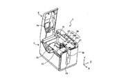
- FIG. 2 is a perspective view of the printer 1 with the open / close lid 3 opened.
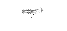
- FIG. 2 is a cross-sectional view of the print medium M used in the printing apparatus 1 as viewed in the medium width direction Y.
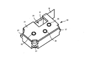
- FIG. 2 is a perspective view of a tape cassette 30 stored in the printing apparatus 1;
- FIG. 2 is a perspective view of a cassette storage unit 19 of the printing apparatus 1;
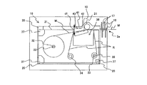
- FIG. 2 is a cross-sectional view of main parts of the printing apparatus 1;
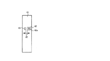
- 5 is a front view of a tape end detection substrate 41 of the printing apparatus 1.
- FIG. 5 is a front view of a tape end detection substrate 41 of the printing apparatus 1.
- FIG. 2 is a block diagram showing the hardware configuration of the printing apparatus 1 and the electronic device 100. It is a flowchart of a tape end judgment process. It is a figure which shows the conveyance state of the to-be-printed medium M and the ink ribbon R. FIG. It is a figure which shows the conveyance state of the to-be-printed medium M and the ink ribbon R. FIG.
- FIG. 1 is a diagram illustrating the configuration of a printing system including a printing apparatus according to the present embodiment.
- FIG. 2 is a perspective view of the printing apparatus with the open / close lid open.
- the printing system illustrated in FIG. 1 includes a printing device 1 and an electronic device 100 that transmits print data to the printing device 1.
- the printing apparatus 1 and the electronic device 100 exchange data by wireless communication or wired communication.
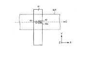
- the direction in which the printing medium M (printing tape) is transported is “conveying direction X”, and the width direction of the printing medium M (printing tape) orthogonal to the transporting direction X is “medium width”.
- the thickness direction of the print medium M (printing tape) is referred to as “thickness direction Z”.
- the X direction, the Y direction, and the Z direction are orthogonal to one another.
- the printing apparatus 1 is a printing apparatus provided with a thermal head (print head) for printing on a medium to be printed, and is, for example, a label printer for printing on a long strip-like medium to be printed M by a single pass method.
- FIG. 3 is a cross-sectional view of the print medium M used in the printing apparatus 1 as viewed in the medium width direction Y.
- the medium to be printed M is, for example, a long tape member having a base material B having a pressure-sensitive adhesive layer S, a pressure-sensitive adhesive layer S (stick surface), and a peelable release paper C covering the pressure-sensitive adhesive layer S. .
- the print medium M may be a long tape member without release paper C.
- printing is performed by the thermal head 10 on the surface of the substrate B opposite to the adhesive layer S (the surface of the substrate B, which is referred to as “printed surface P”).
- the printing method is not particularly limited.
- the length direction of the print-receiving medium M and the ink ribbon R is along the transport path. And transported in the transport direction.
- the printing apparatus 1 includes an apparatus housing 2 and an open / close lid 3 attached to the apparatus housing 2 so as to be openable and closable.
- the device housing 2 is provided with a cassette storage portion 19 for storing the tape cassette 30 inside. Details of the cassette storage unit 19 will be described later.
- operation button 26 on the top surface of the device housing 2, operation buttons 26a, 26b, 26c (hereinafter referred to as "operation button 26") for performing various operations, a lid open / close button 27 for opening the open / close lid 3, etc. It is arranged.
- the device housing 2 is provided with a power cord connection terminal, an external device connection terminal, a storage medium insertion slot, and the like.
- the power supply cord connection terminal may be omitted.
- the open / close lid 3 is disposed to be openable and closable so as to cover the upper portion of the cassette storage unit 19.
- the open / close lid 3 is released by pressing the lid open / close button 27.
- the window 3a is provided on the open / close lid 3 so that it can be visually confirmed whether the tape cassette 30 (see FIG. 4) is stored in the cassette storage portion 19 even when the open / close lid 3 is closed. It is formed.
- a discharge port 2 a is formed on the side surface of the apparatus housing 2 and on the downstream side in the transport direction X of the print medium M. The print medium M on which printing by the thermal head 10 has been performed in the printing apparatus 1 is discharged from the discharge port 2a to the outside of the apparatus.
- FIG. 4 is a perspective view of the tape cassette 30 stored in the printing apparatus 1.
- FIG. 5 is a perspective view of the cassette storage unit 19 of the printing apparatus 1.
- FIG. 6 is a cross-sectional view of relevant parts of the printing apparatus 1 according to the present embodiment.
- the tape cassette 30 shown in FIG. 4 is detachably stored in the cassette storage unit 19 shown in FIG. FIG. 6 shows a state in which the tape cassette 30 is stored in the cassette storage unit 19.
- the tape cassette 30 has a cassette case 31 in which the print medium M and the ink ribbon R are housed, in which the thermal head insertion portion 36 and the engagement portion 37 are formed.
- the cassette case 31 is provided with a tape core 32, an ink ribbon supply core 34, and an ink ribbon winding core 35.
- the print medium M is wound around the tape core 32 inside the cassette case 31 in a roll shape.
- the thermal transfer ink ribbon R is wound in a roll around the ink ribbon supply core 34 inside the cassette case 31 in a state where the tip thereof is wound around the ink ribbon winding core 35.
- the cassette storage unit 19 of the apparatus housing 2 is provided with a plurality of cassette receiving units 20 for supporting the tape cassette 30 at a predetermined position.
- the cassette storage unit 19 further has a plurality of heat generating elements, and the thermal head 10 for printing on the print medium M, the platen roller 21 which is a transport mechanism for transporting the print medium M, and the tape core engaging shaft 22 and an ink ribbon winding drive shaft 23 are provided. Further, a thermistor 13 is embedded in the thermal head 10. The thermistor 13 is a head temperature measurement unit that measures the temperature of the thermal head 10.
- the cassette storage unit 19 is further provided with a tape end detection substrate 41 having a configuration for determining the presence or absence of the remaining amount of the print medium M.
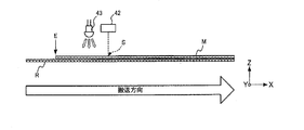
- 7A and 7B are front views of the tape end detection substrate 41 of the printing apparatus 1.
- the tape end detection substrate 41 is provided with an optical sensor 42 and a light source 43.
- the light sensor 42 has a light receiving area 42 a for receiving light.
- the tape end detection substrate 41 provided with the light sensor 42 and the light source 43 is disposed on the upstream side of the thermal head 10 in the transport direction on the transport path C of the print medium M shown in FIG. 7B.
- the end E which is one of the boundaries of the print medium M, is detected by the light sensor 42 by detecting the color or brightness of the conveyance object by the light sensor 42. Whether or not the detection position S has been passed, that is, whether or not the remaining amount of the print medium M is exhausted can be determined. Furthermore, as shown in FIG. 7B, the light sensor 42 and the light source 43 are disposed at positions facing substantially the center of the medium width direction Y of the print medium M and the ink ribbon R in the transport direction of the transport path C. An area facing the light receiving area 42 a of the light sensor 42 in the object to be conveyed is a detection position S.
- the cassette storage unit 19 can store a plurality of types of tape cassettes 30 having different widths of the print medium M. Then, even when any of a plurality of types of tape cassettes 30 having different widths of the print medium M is stored in the cassette storage unit 19, the center in the medium width direction Y of the print medium M is substantially constant. Is configured. As a result, even if any of the plurality of types of tape cassettes 30 having different widths of the print medium M are stored in the cassette storage unit 19, the position is opposed to the approximate center of the medium width direction Y of the print medium M. The light sensor 42 and the light source 43 will be arranged. Therefore, regardless of the width of the print medium M, it is possible to properly determine the presence or absence of the remaining amount of the print medium M.
- the light sensor 42 and the light source 43 are the printing medium M (when the printing medium M has the release paper C
- the distance between the tape end detection substrate 41 and the printing medium M is approximately predetermined in the direction facing the substrate B). It is arrange
- the light source 43 is formed of, for example, a white LED, and when the light sensor 42 detects the color or brightness of the object to be conveyed, it illuminates the object to be conveyed with illumination light.
- the light source 43 emits light including a wavelength range that can be detected by the light sensor 42 in accordance with the sensitivity characteristic of the light sensor 42. That is, the light source 43 is not limited to the white LED as long as the light source 43 can emit light including a desired wavelength range, and, for example, three colors of red (R), green (G), and blue (B)
- the light emitting diode may be constituted by an LED, or an incandescent lamp or a fluorescent lamp.
- the light sensor 42 is a detection device that detects the color or brightness of the object to be conveyed at a position facing the light receiving area 42 a.
- the detection target is the printing medium M or the ink ribbon R
- the light sensor 42 is the printing medium M (if the printing medium M has the release paper C, the release paper C, When the medium to be printed M does not have the release paper C, it is possible to detect the color or brightness of the substrate B) and the color or brightness of the ink ribbon R.
- the light sensor 42 is, for example, a color sensor configured to include a photodiode having filters of red color (R), green color (G) and blue color (B).
- the light sensor 42 converts the intensity of the light detected by each photodiode into, for example, a 16-bit digital value to obtain an RGB value. Therefore, the light sensor 42 detects color information having RGB values according to the detected light spectrum, and outputs this as a detection signal. Thereby, even if the color of the printing medium M and the color of the ink ribbon R are similar colors, the light sensor 42 can detect different RGB values for each color.
- the light sensor 42 sends the detected RGB values to the processor 5 as a detection signal. Therefore, even if the color of the printing medium M and the color of the ink ribbon R are similar colors, the processor 5 is based on the change of the RGB value for the color of the transport object detected by the light sensor 42. It can be determined that the object to be transported at the position facing the light receiving area 42 a of the light sensor 42 has changed from the print medium M to the ink ribbon R.
- the light sensor 42 may detect the brightness of the object to be conveyed. That is, the difference in brightness due to the difference in reflectance of the illuminated surface illuminated by the light source 43 may be detected. In this case, based on the detected brightness, it is determined that the object to be detected has changed from the print medium M to the ink ribbon R.
- the light sensor 43 includes a color sensor, a CCD (Charge-Coupled Device) image sensor, a CMOS (Complementary MOS) image sensor, an infrared sensor, and the like, and the color or brightness of the print medium M as an object to be It may be formed by a sensor that can distinguish the color or brightness of the image.
- the engagement portion 37 provided in the cassette case 31 is supported by the cassette receiving portion 20 provided in the cassette storage portion 19.
- the thermal head 10 is inserted into a thermal head insertion portion 36 formed in the cassette case 31. Further, the tape core 32 of the tape cassette 30 is engaged with the tape core engagement shaft 22, and the ink ribbon take-up core 35 is engaged with the ink ribbon take-up drive shaft 23.
- the print medium M is fed out of the tape core 32 by the rotation of the platen roller 21.
- the ink ribbon winding drive shaft 23 is rotated in synchronization with the platen roller 21
- the ink ribbon R is fed out from the ink ribbon supply core 34 together with the print medium M.
- the print medium M and the ink ribbon R are conveyed in an overlapping state.
- the ink ribbon R is heated by the thermal head 10 when passing between the thermal head 10 and the platen roller 21, the ink is transferred to the print medium M and printing is performed.
- the used ink ribbon R that has passed between the thermal head 10 and the platen roller 21 is wound around the ink ribbon winding core 35.
- the printed medium to be printed M which has passed between the thermal head 10 and the platen roller 21 is cut by the half cut device 16 and the full cut device 17 and discharged from the discharge port 2 a.
- the length of the print medium M is shorter than the length of the ink ribbon R. Then, since the end E of the print medium M is not fixed to the tape core 32, the end E of the print medium M finally passes in front of the light sensor 42 and is discharged from the discharge port 2a.
- the tape end detection substrate 41 on which the light sensor 42 is disposed is disposed on the cassette storage unit 19 side. Therefore, the detection of the color or brightness of the object to be conveyed by the light sensor 42 is performed from the side of the medium to be printed M among the medium to be printed M and the ink ribbon R conveyed in the overlapping state. Therefore, when the medium to be printed M remains, the light sensor 42 separates the medium to be printed M (when the medium to be printed M has the release paper C, the release paper C and the medium to be printed M are peeled off) If the paper C is not present, the color or brightness of the substrate B) is detected.
- the light sensor 42 After the print medium M is conveyed and the end (boundary) E of the print medium M passes a position (detection position S) facing the light sensor 42, the light sensor 42 detects the color of the ink ribbon R or Detect the brightness.
- the processor 5 recognizes that the object to be detected by the light sensor 42 has changed from the medium to be printed M to the ink ribbon R on the basis of the change in color or brightness detected by the light sensor 42, whereby the medium 5 is printed. It can be determined whether the end E has passed the detection position S and the remaining amount of the print medium M has run out.
- FIG. 8 is a block diagram showing the hardware configuration of the printing apparatus 1 and the electronic device 100.
- the printing apparatus 1 includes a processor 5, a read only memory (ROM) 6, a random access memory (RAM) 7, in addition to the thermal head 10, the thermistor 13, the half cut device 16, the full cut device 17 and the platen roller 21 described above.
- a communication interface (IF) 8 a head drive circuit 9, a transport motor drive circuit 11, a stepping motor 12, a cutter motor drive circuit 14, a cutter motor 15, and a power supply circuit 40 are provided.
- At least the processor 5, the ROM 6, and the RAM 7 constitute a computer of the printing apparatus 1.
- the processor 5 includes, for example, a central processing unit (CPU).
- the processor 5 controls the operation of each unit of the printing apparatus 1 by developing the program stored in the ROM 6 in the RAM 7 and executing the program.
- the processor 5 supplies, for example, control signals (strobe signals, latch signals, clock signals) and print data to the head drive circuit 9 and controls the thermal head 10 via the head drive circuit 9.
- the processor 5 also controls a motor (stepping motor 12 and cutter motor 15) via a motor drive circuit (transfer motor drive circuit 11 and cutter motor drive circuit 14).
- the processor 5 determines whether or not the end E of the print medium M has passed the detection position S based on the change in color or brightness of the transport object detected by the light sensor 42, ie, the print medium M Determine if there is a remaining amount. Specifically, when the light sensor 42 detects the color of the object to be transported, the processor 5 detects a red color (R), a green color (G), and a blue color (RGB values) included in the RGB values detected by the light sensor 42. Whether or not the remaining amount of the print medium M is present is determined based on whether or not the value of at least one of B) has changed by a predetermined ratio or more.
- the processor 5 determines whether the end E of the print medium M has passed the detection position S based on the information on the color of the release paper C detected by the light sensor 42 and the information on the color of the ink ribbon R That is, it is determined whether there is a remaining amount. Therefore, it can be determined whether there is the remaining amount of the printing medium M with the release paper C attached. Details of the determination as to whether or not there is a remaining amount of the print medium M by the processor 5 will be described later.
- the ROM 6 stores a print program for printing on the print medium M, and various data (for example, fonts and the like) necessary for executing the print program.
- the ROM 6 also functions as a storage medium in which a program readable by the processor 5 is stored.
- the RAM 7 includes a print data storage unit that stores data (hereinafter referred to as print data) indicating a pattern of print content. Furthermore, the RAM 7 includes a display data storage unit that stores display data.
- the communication interface 8 exchanges data with an external device (for example, the electronic device 100) by wired communication or wireless communication.
- the head drive circuit 9 drives the thermal head 10 based on the control signal and print data supplied from the processor 5.
- the thermal head 10 is a print head having a plurality of heating elements 10 a arranged in the main scanning direction.
- the head drive circuit 9 selectively applies a current to any of the plurality of heating elements 10a in accordance with the print data output from the head drive circuit 9 during the conduction period specified by the strobe signal supplied from the processor 5. By flowing, one of the plurality of heating elements 10a generates heat to heat the ink ribbon R. Thereby, the thermal head 10 performs printing one line at a time on the print medium M by thermal transfer. That is, the printing apparatus 1 is a thermal line printer.
- the transport motor drive circuit 11 drives the stepping motor 12.
- the stepping motor 12 rotates the platen roller 21.
- the platen roller 21 is a transport mechanism that is rotated by the power of the stepping motor 12 and transports the print medium M in the longitudinal direction (sub scanning direction) of the print medium M.
- the cutter motor drive circuit 14 drives the cutter motor 15.
- the half cut device 16 and the full cut device 17 operate by the power of the cutter motor 15 to half cut or full cut the print medium M.
- the full cut is an operation of cutting the substrate of the printing medium M along the width direction together with the release paper, and the half cut is an operation of cutting only the substrate along the width direction.
- the power supply circuit 40 is a power supply unit that generates an output voltage from a DC voltage (for example, 24 V) from the external power supply D and supplies power to each unit of the printing apparatus 1.
- the electronic device 100 is a portable computer, such as a smartphone or a tablet terminal, provided with a display device 101 and an input device 102.
- the display device 101 may be, for example, a liquid crystal display or an organic electroluminescent (organic EL) display.
- the input device 102 is, for example, a touch panel.
- the electronic device 100 includes a display driving circuit 103, a communication interface (IF) 104, a ROM 105, a RAM 106, and a processor 107 in addition to the above-described configuration.
- the display drive circuit 103 is, for example, a liquid crystal display driver circuit or an organic EL display driver circuit.
- the processor 107 is an operation unit, and displays an error message sent from the printing apparatus 1 on the display device 101 by executing an application program.
- FIG. 9 is a flowchart of the tape end determination process.
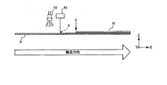
- the tape end determination process will be described in conjunction with FIGS. 10A and 10B.
- 10A and 10B are diagrams showing the transport state of the print medium M and the ink ribbon R.
- the medium to be printed M has a release paper C.
- the surface of the release paper C on the side of the light sensor 42 has a color such as cream or light blue.
- the ink ribbon R has, for example, black, red and white.
- 10A is a state before the end E of the print medium M passes the detection position S on the transport path C by the light sensor 42, and the print medium M and the ink ribbon R are viewed from the width direction Y. It is a schematic diagram which shows a conveyance state.
- FIG. 10B is a schematic view showing the transport state of the print medium M and the ink ribbon R as viewed in the width direction Y after the end E of the print medium M has passed the detection position S by the optical sensor 42. It is.
- the light sensor 42 detects the color at the detection position S of the transport object
- the color information may be bright even when the light sensor 42 detects the brightness at the detection position S of the transport object
- the processing can be performed in the same way by simply replacing the information with the
- the tape end determination process a process of determining the presence or absence of the remaining amount of the print tape as the print medium M is performed.
- the printing apparatus 1 starts the tape end determination process shown in FIG. 9 based on the print start instruction.
- the processor 5 first operates the light sensor 42 before the medium to be printed M is transported, and acquires the RGB value of the detection signal detected by the light sensor 42 as an initial value (step S101).
- the end E of the printing medium M is upstream of the detection position S by the optical sensor 42 in the conveyance direction of the conveyance path C of the printing medium M positioned.
- the light sensor 42 faces the release paper C of the medium to be printed M, and the red value (R), the green value (G) and the red value corresponding to the color of the release paper C are An RGB value containing a blue value (B) is detected and sent to the processor 5 as a detection signal. Then, the processor 5 sets the red value (R), the green value (G) and the blue value (B) included in the RGB values of the detection signal sent from the light sensor 42 to initial values R before and G before , respectively. Acquire as B before and store in the RAM 7.
- the processor 5 turns on the thermal head 10 and turns on the stepping motor 12.
- the platen roller 21 rotates in the transport direction, transport of the print medium M starts, and printing on the print medium M is performed based on the print data.
- the processor 5 turns the thermal head 10 off and turns the stepping motor 12 off.
- the rotation of the platen roller 21 is stopped, the conveyance of the print medium M is ended, and the printing on the print medium M is ended (step S102).
- the processor 5 operates the light sensor 42 after the conveyance of the medium to be printed M is completed, and acquires the RGB value of the detection signal detected by the light sensor 42 (step S103).
- the end E of the print medium M is the transport path C of the print medium M.
- the light sensor 42 is positioned upstream of the detection position S by the light sensor 42. In this case, the print medium M and the ink ribbon R overlap with each other at the detection position S by the light sensor 42, and the light sensor 42 faces the release paper C of the print medium M.
- the light sensor 42 detects RGB values including a red value (R), a green value (G) and a blue value (B) corresponding to the color of the release paper C of the print medium M present at the detection position S , This is sent to the processor 5 as a detection signal. Then, after the conveyance of the print medium M, the processor 5 detects the red value (R), the green value (G) and the blue value (B) included in the RGB values of the detection signal sent from the light sensor 42 respectively.
- the RGB values R after , G after , and B after are acquired.
- the end E of the print medium M is the transport path C of the print medium M. In the transport direction, it is located downstream of the detection position S by the light sensor 42.
- the print medium M is not present at the detection position S by the light sensor 42, and only the ink ribbon R is present, and the light sensor 42 faces the ink ribbon R. Therefore, the light sensor 42 detects RGB values including a red value (R), a green value (G) and a blue value (B) corresponding to the color of the ink ribbon R present at the detection position S, and detects the RGB values As the processor 5.
- the processor 5 detects the red value (R), the green value (G) and the blue value (B) included in the RGB values of the detection signal sent from the light sensor 42 respectively.
- the RGB values R after , G after , and B after are acquired.
- the processor 5 detects the initial values (R before , G before , B before ) of RGB values detected by the light sensor 42 before the medium to be printed M is conveyed, and the light sensor 42 detects the initial values of the medium to be printed M It is determined whether or not there is a change in the RGB values (R after , G after , B after ) (step S104).
- the processor 5 calculates the initial values R before , G before and B before of the RGB values before conveyance of the medium to be printed M acquired in step S101 and the values of the medium to be printed M acquired in step S103. The rate of change of each of the transported RGB values R after , G after , and B after is determined.
- the processor 5 determines whether at least one of the red value (R), the green value (G) and the blue value (B) included in the RGB values has changed by a predetermined ratio (threshold) or more Determine Specifically, the processor 5 determines whether at least one of the red value (R), the green value (G) and the blue value (B) included in the RGB values has changed by a predetermined threshold or more. Determine if In the present embodiment, the threshold is set to, for example, 10%. The value of the threshold is not limited to this, and can be set to any ratio.
- the processor 5 determines whether at least one of the following (formula 1) to (formula 3) is satisfied.
- the processor 5 determines the RGB values acquired before and after the conveyance of the print medium M It is determined that the information on the color of the release paper C of the print medium M is indicated. In this case, the processor 5 determines that the end E of the print medium M has not yet passed on the transport path C, and the remaining amount of the print medium M still remains. When this process ends, the tape end determination process ends.
- the processor 5 determines the RGB values acquired after the conveyance of the print medium M It is determined that the color information of the ink ribbon R is indicated instead of the color information of the release paper C of the print medium M. That is, the processor 5 detects that the object to be conveyed at the detection position S has changed from the release paper C of the print medium M to the ink ribbon R based on the change in the color information detected by the light sensor 42 Thus, it is determined that the end E of the print medium M has passed the detection position S on the transport path C. If the processor 5 determines that the end E of the print medium M has passed the detection position S, it determines that the remaining amount of the print medium M is exhausted.
- the processor 5 determines that the remaining amount of the print medium M is exhausted based on the RGB values detected before and after the conveyance of the print medium M, for example, the display device 101 of the electronic device 100 loses the remaining amount of the print medium M The remaining amount of the print medium M is exhausted by displaying an error message to the effect or outputting a message sound indicating that the remaining amount of the print medium M is exhausted by a speaker (not shown) of the electronic device 100 or the like. Control to notify that is performed (step S105). Thus, the user can be clearly notified that the remaining amount of the print medium M has run out. Also, the processor 5 stops the operation of the printing apparatus 1 (step S106).
- the processor 5 temporarily stops the conveyance and printing operations of the printing apparatus 1 by stopping the supply of power to the thermal head 10 and the stepping motor 12 until the tape cassette 30 is replaced with another tape cassette 30. Do. Then, when the processor 5 is replaced with another tape cassette 30, the processor 5 releases the stop of the supply of power to the thermal head 10 and the stepping motor 12. When this process ends, the tape end determination process ends. As a result, when the remaining amount of the print medium M runs out, it is possible to prevent an idle run of the printing by the thermal head 10 in advance. Thereby, the components of the printing apparatus 1 such as the thermal head 10 and the platen roller 21 can be obtained. Can be protected.
- the printing apparatus 1 it is determined whether or not there is a remaining amount of the print medium M, based on the change in the color or the brightness of the transport object detected by the light sensor 42. Thus, it is possible to determine whether or not there is a remaining amount of the print medium M without applying any processing to the print medium M. In addition, since it is determined whether or not there is a remaining amount of the print medium M based on the difference in color information between the ink ribbon R and the print medium M, external light is transmitted to this determination. Also, it can be made less susceptible to environmental changes such as temperature changes.
- the print medium M since it is determined whether or not there is the remaining amount of the print medium M based on the change in color or brightness, any color or material in the relationship between the print medium M and the ink ribbon R, Even when a combination of structures is adopted, it can be determined whether or not there is a remaining amount of the print medium M. For example, even if the structure of the print medium M is a type that does not have the release paper C, the presence or absence of the remaining amount of the print medium M can be determined.
- the processor 5 detects the red value (R), the green value (G), and the RGB value including the blue value (B) detected by the light sensor 42.
- the presence or absence of the remaining amount of the print medium M is determined based on whether at least one of the values has changed by a predetermined ratio or more. Thereby, for example, even if the ink ribbon R and the print medium M have the same color, the presence or absence of the remaining amount of the print medium M can be determined.
- the light sensor 42 detects information on the color of the print medium M on the irradiation surface illuminated by the light source 43 and information on the color of the ink ribbon R. Therefore, even in a dark environment, the print medium M and the ink ribbon R can be distinguished and detected. Thereby, the determination accuracy of the presence or absence of the remaining amount of the print medium M can be improved. Further, since the print medium M and the ink ribbon R are formed of different materials, even if the colors of the print medium M and the ink ribbon R are similar, the reflectances are different from each other. Therefore, the print medium M and the ink ribbon R can be distinguished and detected based on the difference in brightness due to the difference in reflectance. Thereby, the determination accuracy of the presence or absence of the remaining amount of the print medium M can be improved.
- the processor 5 further includes information on the color detected by the light sensor 42 before the print medium M is conveyed, and information on the color detected by the light sensor 42 after the print medium M is conveyed. Based on the detection, the presence or absence of the remaining amount of the print medium M is detected. Therefore, since the detection interval by the light sensor 42 is relatively short, in the determination of the presence or absence of the remaining amount of the print medium M, the influence of environmental changes such as external light and temperature change on the light sensor 42 using a semiconductor Therefore, the determination accuracy of the presence or absence of the remaining amount of the print medium M can be improved. Further, in the prior art, in order to detect the end of the print medium, the identification mark formed on the print medium is detected, and for this purpose, it is necessary to continuously detect the identification mark.
- the detection by the light sensor 42 may be performed only twice before and after the medium to be printed M is transported. Therefore, it is possible to suppress the power consumption related to the determination of the presence or absence of the remaining amount of the print medium M, and to reduce the processing load on the processor 5.
- the processor 5 displays an error message on the display device 101 of the electronic device 100 in the above-described embodiment
- the present invention is not limited to this.
- the display device such as a display or a light emitting diode
- the processor 5 determines that the remaining amount of the print medium M is exhausted
- an error that the remaining amount of the print medium M is exhausted Control may be performed to display a message on the display device of the printing apparatus 1.
- the user can be clearly notified that the remaining amount of the print medium M has run out.
- the presence or absence of the remaining amount of the print medium M based on the information on the color or brightness of the print medium M detected by the light sensor 42 and the information on the color or brightness of the ink ribbon R
- the print medium M is created in a plurality of colors (for example, three colors) for each length, and information on the color or brightness of the print medium M (release paper C) which fluctuates for each length, and the ink ribbon R
- the presence or absence of the remaining amount of the print medium M may be determined based on the difference between the color or the brightness information.
- the processor 5 performs control to display a message according to the remaining amount.
- the light sensor 42 is disposed upstream of the thermal head 10 in the transport direction of the transport path C of the print medium M, but the present invention is not limited to this.
- the light sensor 42 may be disposed on the conveyance path C in which the print medium M and the ink ribbon R overlap and is conveyed, such as downstream of the thermal head 10.
- the processor 5 detects the information on the color or brightness detected by the light sensor 42 before the print medium M is conveyed and the light sensor 42 after the print medium M is conveyed.
- the example which determines the presence or absence of the residual amount of a to-be-printed medium based on the change of the color or brightness information was shown, it is not this limitation.
- the light sensor 42 detects color or brightness information continuously (for example, every one second) while the print medium M is transported, and the processor 5 detects the color or the brightness continuously detected. The presence or absence of the remaining amount of the print medium M may be determined on the basis of the difference in the size information.
- the processor 5 stops the conveyance of the printing apparatus 1 and the printing operation by stopping the supply of power to the thermal head 10 and the stepping motor 12. As a result, by preventing idle printing of the print by the thermal head 10, components of the printing apparatus 1 such as the thermal head 10 and the platen roller 21 can be protected. Furthermore, by preventing the useless operation of the printing apparatus 1, the power consumption of the printing apparatus 1 can be reduced.
- the processor 5 determines the initial values of the RGB values detected by the light sensor 42 before the conveyance of the print medium M, and the RGB values detected by the light sensor 42 after the conveyance of the print medium M ends.
- the processor 5 stores the RGB value detected only once as an initial value, and detects the initial value of the stored RGB value and the light sensor 42 after the conveyance of the print medium M is completed. It may be determined whether there is a change in the RGB values.
- the detection of the color or the brightness of the print medium by the light sensor 42 is performed from the print medium M side, but the present invention is not limited to this.
- the detection of the color or brightness of the print medium by the optical sensor 42 may be performed from the ink ribbon R side.
Landscapes
- Accessory Devices And Overall Control Thereof (AREA)
- Electronic Switches (AREA)
- Printers Characterized By Their Purpose (AREA)
- Handling Of Sheets (AREA)
- Handling Of Continuous Sheets Of Paper (AREA)
Priority Applications (1)
| Application Number | Priority Date | Filing Date | Title |
|---|---|---|---|
| CN201880043026.0A CN110799340B (zh) | 2017-06-26 | 2018-04-17 | 印刷装置、印刷控制方法及记录介质 |
Applications Claiming Priority (2)
| Application Number | Priority Date | Filing Date | Title |
|---|---|---|---|
| JP2017-123918 | 2017-06-26 | ||
| JP2017123918A JP7047266B2 (ja) | 2017-06-26 | 2017-06-26 | 印刷装置、印刷装置の印刷制御方法、及び、プログラム |
Publications (1)
| Publication Number | Publication Date |
|---|---|
| WO2019003593A1 true WO2019003593A1 (ja) | 2019-01-03 |
Family
ID=64741340
Family Applications (1)
| Application Number | Title | Priority Date | Filing Date |
|---|---|---|---|
| PCT/JP2018/015850 Ceased WO2019003593A1 (ja) | 2017-06-26 | 2018-04-17 | 印刷装置、印刷制御方法、及び、記録媒体 |
Country Status (3)
| Country | Link |
|---|---|
| JP (1) | JP7047266B2 (enExample) |
| CN (1) | CN110799340B (enExample) |
| WO (1) | WO2019003593A1 (enExample) |
Families Citing this family (3)
| Publication number | Priority date | Publication date | Assignee | Title |
|---|---|---|---|---|
| JP7367430B2 (ja) | 2019-09-30 | 2023-10-24 | ブラザー工業株式会社 | 印刷装置 |
| US12053980B2 (en) * | 2022-08-10 | 2024-08-06 | Honeywell International Inc. | Printer media low sensing using motor current drawn when feeding |
| CN116749658B (zh) * | 2023-08-21 | 2023-11-14 | 武汉精臣智慧标识科技有限公司 | 一种rfid标签打印机及其读写方法 |
Citations (5)
| Publication number | Priority date | Publication date | Assignee | Title |
|---|---|---|---|---|
| JP2001146362A (ja) * | 1999-11-19 | 2001-05-29 | Mitsubishi Paper Mills Ltd | ウェブ製造工程におけるウェブ切れ検知装置 |
| JP2005001887A (ja) * | 2003-05-21 | 2005-01-06 | Seiko Epson Corp | 印刷装置、印刷装置の制御方法およびプログラム |
| JP2013075373A (ja) * | 2011-09-29 | 2013-04-25 | Canon Inc | 記録装置 |
| JP2015063045A (ja) * | 2013-09-24 | 2015-04-09 | カシオ計算機株式会社 | 印刷装置、印刷方法、プログラム、及びテープ |
| JP2015066719A (ja) * | 2013-09-27 | 2015-04-13 | セイコーエプソン株式会社 | 印刷装置、及び、印刷装置の制御方法 |
Family Cites Families (8)
| Publication number | Priority date | Publication date | Assignee | Title |
|---|---|---|---|---|
| JPS6083862A (ja) * | 1983-10-17 | 1985-05-13 | Fuji Xerox Co Ltd | 多色転写型感熱記録装置 |
| JPS61172480A (ja) * | 1985-01-25 | 1986-08-04 | Matsushita Electric Ind Co Ltd | 多色熱転写記録装置 |
| JPH08127167A (ja) * | 1994-11-01 | 1996-05-21 | Arutetsuku Kk | ロール紙終端検知装置及び方法 |
| JP2000071589A (ja) * | 1998-06-16 | 2000-03-07 | Alps Electric Co Ltd | インクリボン集合体およびこのインクリボン集合体を使用する熱転写プリンタ |
| CN1319752C (zh) * | 2003-05-21 | 2007-06-06 | 精工爱普生株式会社 | 打印装置及打印装置的控制方法 |
| JP2008009598A (ja) * | 2006-06-28 | 2008-01-17 | Konica Minolta Business Technologies Inc | 印刷制御装置、印刷制御プログラム、および印刷制御方法 |
| JP2011104828A (ja) * | 2009-11-16 | 2011-06-02 | Canon Inc | ロール状記録媒体およびロール状記録媒体の終端検知方法 |
| US9132674B2 (en) * | 2013-09-27 | 2015-09-15 | Seiko Epson Corporation | Printer and control method of a printer |
-
2017
- 2017-06-26 JP JP2017123918A patent/JP7047266B2/ja active Active
-
2018
- 2018-04-17 WO PCT/JP2018/015850 patent/WO2019003593A1/ja not_active Ceased
- 2018-04-17 CN CN201880043026.0A patent/CN110799340B/zh active Active
Patent Citations (5)
| Publication number | Priority date | Publication date | Assignee | Title |
|---|---|---|---|---|
| JP2001146362A (ja) * | 1999-11-19 | 2001-05-29 | Mitsubishi Paper Mills Ltd | ウェブ製造工程におけるウェブ切れ検知装置 |
| JP2005001887A (ja) * | 2003-05-21 | 2005-01-06 | Seiko Epson Corp | 印刷装置、印刷装置の制御方法およびプログラム |
| JP2013075373A (ja) * | 2011-09-29 | 2013-04-25 | Canon Inc | 記録装置 |
| JP2015063045A (ja) * | 2013-09-24 | 2015-04-09 | カシオ計算機株式会社 | 印刷装置、印刷方法、プログラム、及びテープ |
| JP2015066719A (ja) * | 2013-09-27 | 2015-04-13 | セイコーエプソン株式会社 | 印刷装置、及び、印刷装置の制御方法 |
Also Published As
| Publication number | Publication date |
|---|---|
| JP2019006018A (ja) | 2019-01-17 |
| CN110799340A (zh) | 2020-02-14 |
| JP7047266B2 (ja) | 2022-04-05 |
| CN110799340B (zh) | 2021-09-14 |
Similar Documents
| Publication | Publication Date | Title |
|---|---|---|
| US7938588B2 (en) | Thermal printer having first and second ring-like conveyance paths | |
| US10710379B2 (en) | Printer, printing control method of printer, and recording medium | |
| WO2019003593A1 (ja) | 印刷装置、印刷制御方法、及び、記録媒体 | |
| CN110014751A (zh) | 印刷装置、印刷控制方法以及存储介质 | |
| CN110271308A (zh) | 印刷装置、控制方法以及非暂时性存储介质 | |
| JP7231088B2 (ja) | 印刷装置、印刷装置の制御方法、及び、プログラム | |
| JP2613230B2 (ja) | 熱転写記録装置 | |
| US11034171B2 (en) | Printer and control method for printer | |
| JP7024363B2 (ja) | 印刷装置、印刷装置の制御方法、及び、プログラム | |
| JP2006240202A (ja) | 印刷装置用リボン、該リボンを用いる印刷装置、リボン種類検知方法 | |
| JP2001322329A (ja) | 記録装置 | |
| JP2014061603A (ja) | 印刷装置及び印刷装置の印刷制御方法 | |
| JP7591895B2 (ja) | 画像形成装置 | |
| JPS60257282A (ja) | 画像形成装置 | |
| JP5999410B2 (ja) | 印刷装置 | |
| JP2004322405A (ja) | インクリボン | |
| JP4581894B2 (ja) | 熱転写印刷装置 | |
| JPS6260679A (ja) | 熱転写記録装置 | |
| JPH11157159A (ja) | プリンタ装置 | |
| JP2003285567A (ja) | インクリボンシートセット、インクリボンカセットおよび印刷装置 | |
| JP2002229123A (ja) | プロジェクタ | |
| JP2007223200A (ja) | 印刷装置及び該印刷装置のインクリボン残量検出方法 | |
| JPH1120284A (ja) | 印字装置 | |
| JP2016165832A (ja) | インクリボンカセットおよびプリントシステム | |
| JPH04275179A (ja) | 熱転写用カラーフイルムおよびその判別方法 |
Legal Events
| Date | Code | Title | Description |
|---|---|---|---|
| 121 | Ep: the epo has been informed by wipo that ep was designated in this application |
Ref document number: 18823803 Country of ref document: EP Kind code of ref document: A1 |
|
| NENP | Non-entry into the national phase |
Ref country code: DE |
|
| 122 | Ep: pct application non-entry in european phase |
Ref document number: 18823803 Country of ref document: EP Kind code of ref document: A1 |