WO2019003593A1 - Printing device, printing control method, and recording medium - Google Patents
Printing device, printing control method, and recording medium Download PDFInfo
- Publication number
- WO2019003593A1 WO2019003593A1 PCT/JP2018/015850 JP2018015850W WO2019003593A1 WO 2019003593 A1 WO2019003593 A1 WO 2019003593A1 JP 2018015850 W JP2018015850 W JP 2018015850W WO 2019003593 A1 WO2019003593 A1 WO 2019003593A1
- Authority
- WO
- WIPO (PCT)
- Prior art keywords
- printing
- print medium
- color
- printing apparatus
- medium
- Prior art date
Links
Images


Classifications
-
- B—PERFORMING OPERATIONS; TRANSPORTING
- B41—PRINTING; LINING MACHINES; TYPEWRITERS; STAMPS
- B41J—TYPEWRITERS; SELECTIVE PRINTING MECHANISMS, i.e. MECHANISMS PRINTING OTHERWISE THAN FROM A FORME; CORRECTION OF TYPOGRAPHICAL ERRORS
- B41J11/00—Devices or arrangements of selective printing mechanisms, e.g. ink-jet printers or thermal printers, for supporting or handling copy material in sheet or web form
- B41J11/36—Blanking or long feeds; Feeding to a particular line, e.g. by rotation of platen or feed roller
- B41J11/42—Controlling printing material conveyance for accurate alignment of the printing material with the printhead; Print registering
-
- B—PERFORMING OPERATIONS; TRANSPORTING
- B41—PRINTING; LINING MACHINES; TYPEWRITERS; STAMPS
- B41J—TYPEWRITERS; SELECTIVE PRINTING MECHANISMS, i.e. MECHANISMS PRINTING OTHERWISE THAN FROM A FORME; CORRECTION OF TYPOGRAPHICAL ERRORS
- B41J15/00—Devices or arrangements of selective printing mechanisms, e.g. ink-jet printers or thermal printers, specially adapted for supporting or handling copy material in continuous form, e.g. webs
- B41J15/04—Supporting, feeding, or guiding devices; Mountings for web rolls or spindles
-
- B—PERFORMING OPERATIONS; TRANSPORTING
- B41—PRINTING; LINING MACHINES; TYPEWRITERS; STAMPS
- B41J—TYPEWRITERS; SELECTIVE PRINTING MECHANISMS, i.e. MECHANISMS PRINTING OTHERWISE THAN FROM A FORME; CORRECTION OF TYPOGRAPHICAL ERRORS
- B41J17/00—Mechanisms for manipulating page-width impression-transfer material, e.g. carbon paper
- B41J17/32—Detachable carriers or holders for impression-transfer material mechanism
-
- B—PERFORMING OPERATIONS; TRANSPORTING
- B41—PRINTING; LINING MACHINES; TYPEWRITERS; STAMPS
- B41J—TYPEWRITERS; SELECTIVE PRINTING MECHANISMS, i.e. MECHANISMS PRINTING OTHERWISE THAN FROM A FORME; CORRECTION OF TYPOGRAPHICAL ERRORS
- B41J2/00—Typewriters or selective printing mechanisms characterised by the printing or marking process for which they are designed
- B41J2/315—Typewriters or selective printing mechanisms characterised by the printing or marking process for which they are designed characterised by selective application of heat to a heat sensitive printing or impression-transfer material
- B41J2/32—Typewriters or selective printing mechanisms characterised by the printing or marking process for which they are designed characterised by selective application of heat to a heat sensitive printing or impression-transfer material using thermal heads
- B41J2/325—Typewriters or selective printing mechanisms characterised by the printing or marking process for which they are designed characterised by selective application of heat to a heat sensitive printing or impression-transfer material using thermal heads by selective transfer of ink from ink carrier, e.g. from ink ribbon or sheet
-
- B—PERFORMING OPERATIONS; TRANSPORTING
- B41—PRINTING; LINING MACHINES; TYPEWRITERS; STAMPS
- B41J—TYPEWRITERS; SELECTIVE PRINTING MECHANISMS, i.e. MECHANISMS PRINTING OTHERWISE THAN FROM A FORME; CORRECTION OF TYPOGRAPHICAL ERRORS
- B41J29/00—Details of, or accessories for, typewriters or selective printing mechanisms not otherwise provided for
- B41J29/46—Applications of alarms, e.g. responsive to approach of end of line
- B41J29/48—Applications of alarms, e.g. responsive to approach of end of line responsive to breakage or exhaustion of paper or approach of bottom of paper
-
- B—PERFORMING OPERATIONS; TRANSPORTING
- B41—PRINTING; LINING MACHINES; TYPEWRITERS; STAMPS
- B41J—TYPEWRITERS; SELECTIVE PRINTING MECHANISMS, i.e. MECHANISMS PRINTING OTHERWISE THAN FROM A FORME; CORRECTION OF TYPOGRAPHICAL ERRORS
- B41J3/00—Typewriters or selective printing or marking mechanisms characterised by the purpose for which they are constructed
- B41J3/36—Typewriters or selective printing or marking mechanisms characterised by the purpose for which they are constructed for portability, i.e. hand-held printers or laptop printers
Definitions
- the present specification relates to a printing apparatus, a printing control method of the printing apparatus, and a recording medium.
- a printing apparatus for producing a print tape piece (label) on which characters and the like are printed by printing characters and the like on a long print medium (print tape) and then cutting it
- a tape cassette containing a print medium used for printing.
- the end of the print medium can be detected by detecting the identification mark formed on the print medium before the remaining amount of the print medium in the tape cassette is exhausted.
- a printing apparatus provided (see, for example, Japanese Patent Application Laid-Open No. 2006-181829).
- the end of the print medium can be detected by using the technology described in Japanese Patent Application Laid-Open No. 2006-181829, in order to use this technology, the identification mark is processed on the print medium. I had to.
- the printing apparatus includes a first member and a second member in which colors included in respective regions of at least one surface are different from each other, or brightness in respective regions of at least one surface is different from each other.
- the color or the brightness of the object to be conveyed which is conveyed in a state in which a plurality of members having a plurality of members are viewed from the at least one surface side based on the detection result detected from the at least one surface side
- the processor includes: a processor that detects a boundary of one of the first member and the second member of the transport object; and a print head that performs printing on at least a part of the transport object.
- the printing apparatus includes a print head that performs printing, and a detection device that detects a color or brightness of an object.
- the printing control method includes a plurality of first members and second members in which colors included in respective regions of at least one surface are different from each other, or brightness in respective regions of at least one surface is different from each other.
- the color or brightness of the object to be conveyed conveyed in a state in which the members are overlapped is detected from the at least one surface side by the detection device, and viewed from the at least one surface side based on the detection result.
- the boundary of one of the first member and the second member of the object to be conveyed is detected.
- a recording medium is a computer of a printing apparatus having a print head for printing, wherein colors included in respective areas of at least one side are different from each other, or respective areas of at least one side are different Detecting the color or brightness of the object to be conveyed conveyed in a state in which a plurality of members having first and second members different in brightness from each other are overlapped from the at least one surface side by the detection device
- a readable program for executing a process of causing one of the first member and the second member of the object to be transferred to be detected as viewed from the at least one surface based on the detection result Record.
- FIG. 1 is a diagram illustrating the configuration of a printing system including a printing apparatus 1;
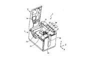
- FIG. 2 is a perspective view of the printer 1 with the open / close lid 3 opened.
- FIG. 2 is a cross-sectional view of the print medium M used in the printing apparatus 1 as viewed in the medium width direction Y.
- FIG. 2 is a perspective view of a tape cassette 30 stored in the printing apparatus 1;
- FIG. 2 is a perspective view of a cassette storage unit 19 of the printing apparatus 1;
- FIG. 2 is a cross-sectional view of main parts of the printing apparatus 1;
- 5 is a front view of a tape end detection substrate 41 of the printing apparatus 1.
- FIG. 5 is a front view of a tape end detection substrate 41 of the printing apparatus 1.
- FIG. 2 is a block diagram showing the hardware configuration of the printing apparatus 1 and the electronic device 100. It is a flowchart of a tape end judgment process. It is a figure which shows the conveyance state of the to-be-printed medium M and the ink ribbon R. FIG. It is a figure which shows the conveyance state of the to-be-printed medium M and the ink ribbon R. FIG.
- FIG. 1 is a diagram illustrating the configuration of a printing system including a printing apparatus according to the present embodiment.
- FIG. 2 is a perspective view of the printing apparatus with the open / close lid open.
- the printing system illustrated in FIG. 1 includes a printing device 1 and an electronic device 100 that transmits print data to the printing device 1.
- the printing apparatus 1 and the electronic device 100 exchange data by wireless communication or wired communication.
- the direction in which the printing medium M (printing tape) is transported is “conveying direction X”, and the width direction of the printing medium M (printing tape) orthogonal to the transporting direction X is “medium width”.
- the thickness direction of the print medium M (printing tape) is referred to as “thickness direction Z”.
- the X direction, the Y direction, and the Z direction are orthogonal to one another.
- the printing apparatus 1 is a printing apparatus provided with a thermal head (print head) for printing on a medium to be printed, and is, for example, a label printer for printing on a long strip-like medium to be printed M by a single pass method.
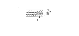
- FIG. 3 is a cross-sectional view of the print medium M used in the printing apparatus 1 as viewed in the medium width direction Y.
- the medium to be printed M is, for example, a long tape member having a base material B having a pressure-sensitive adhesive layer S, a pressure-sensitive adhesive layer S (stick surface), and a peelable release paper C covering the pressure-sensitive adhesive layer S. .
- the print medium M may be a long tape member without release paper C.
- printing is performed by the thermal head 10 on the surface of the substrate B opposite to the adhesive layer S (the surface of the substrate B, which is referred to as “printed surface P”).
- the printing method is not particularly limited.
- the length direction of the print-receiving medium M and the ink ribbon R is along the transport path. And transported in the transport direction.
- the printing apparatus 1 includes an apparatus housing 2 and an open / close lid 3 attached to the apparatus housing 2 so as to be openable and closable.
- the device housing 2 is provided with a cassette storage portion 19 for storing the tape cassette 30 inside. Details of the cassette storage unit 19 will be described later.
- operation button 26 on the top surface of the device housing 2, operation buttons 26a, 26b, 26c (hereinafter referred to as "operation button 26") for performing various operations, a lid open / close button 27 for opening the open / close lid 3, etc. It is arranged.
- the device housing 2 is provided with a power cord connection terminal, an external device connection terminal, a storage medium insertion slot, and the like.
- the power supply cord connection terminal may be omitted.
- the open / close lid 3 is disposed to be openable and closable so as to cover the upper portion of the cassette storage unit 19.
- the open / close lid 3 is released by pressing the lid open / close button 27.
- the window 3a is provided on the open / close lid 3 so that it can be visually confirmed whether the tape cassette 30 (see FIG. 4) is stored in the cassette storage portion 19 even when the open / close lid 3 is closed. It is formed.
- a discharge port 2 a is formed on the side surface of the apparatus housing 2 and on the downstream side in the transport direction X of the print medium M. The print medium M on which printing by the thermal head 10 has been performed in the printing apparatus 1 is discharged from the discharge port 2a to the outside of the apparatus.
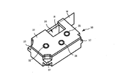
- FIG. 4 is a perspective view of the tape cassette 30 stored in the printing apparatus 1.
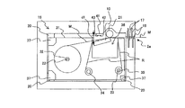
- FIG. 5 is a perspective view of the cassette storage unit 19 of the printing apparatus 1.
- FIG. 6 is a cross-sectional view of relevant parts of the printing apparatus 1 according to the present embodiment.
- the tape cassette 30 shown in FIG. 4 is detachably stored in the cassette storage unit 19 shown in FIG. FIG. 6 shows a state in which the tape cassette 30 is stored in the cassette storage unit 19.
- the tape cassette 30 has a cassette case 31 in which the print medium M and the ink ribbon R are housed, in which the thermal head insertion portion 36 and the engagement portion 37 are formed.
- the cassette case 31 is provided with a tape core 32, an ink ribbon supply core 34, and an ink ribbon winding core 35.
- the print medium M is wound around the tape core 32 inside the cassette case 31 in a roll shape.
- the thermal transfer ink ribbon R is wound in a roll around the ink ribbon supply core 34 inside the cassette case 31 in a state where the tip thereof is wound around the ink ribbon winding core 35.
- the cassette storage unit 19 of the apparatus housing 2 is provided with a plurality of cassette receiving units 20 for supporting the tape cassette 30 at a predetermined position.
- the cassette storage unit 19 further has a plurality of heat generating elements, and the thermal head 10 for printing on the print medium M, the platen roller 21 which is a transport mechanism for transporting the print medium M, and the tape core engaging shaft 22 and an ink ribbon winding drive shaft 23 are provided. Further, a thermistor 13 is embedded in the thermal head 10. The thermistor 13 is a head temperature measurement unit that measures the temperature of the thermal head 10.
- the cassette storage unit 19 is further provided with a tape end detection substrate 41 having a configuration for determining the presence or absence of the remaining amount of the print medium M.
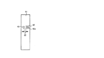
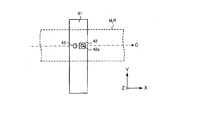
- 7A and 7B are front views of the tape end detection substrate 41 of the printing apparatus 1.
- the tape end detection substrate 41 is provided with an optical sensor 42 and a light source 43.
- the light sensor 42 has a light receiving area 42 a for receiving light.
- the tape end detection substrate 41 provided with the light sensor 42 and the light source 43 is disposed on the upstream side of the thermal head 10 in the transport direction on the transport path C of the print medium M shown in FIG. 7B.
- the end E which is one of the boundaries of the print medium M, is detected by the light sensor 42 by detecting the color or brightness of the conveyance object by the light sensor 42. Whether or not the detection position S has been passed, that is, whether or not the remaining amount of the print medium M is exhausted can be determined. Furthermore, as shown in FIG. 7B, the light sensor 42 and the light source 43 are disposed at positions facing substantially the center of the medium width direction Y of the print medium M and the ink ribbon R in the transport direction of the transport path C. An area facing the light receiving area 42 a of the light sensor 42 in the object to be conveyed is a detection position S.
- the cassette storage unit 19 can store a plurality of types of tape cassettes 30 having different widths of the print medium M. Then, even when any of a plurality of types of tape cassettes 30 having different widths of the print medium M is stored in the cassette storage unit 19, the center in the medium width direction Y of the print medium M is substantially constant. Is configured. As a result, even if any of the plurality of types of tape cassettes 30 having different widths of the print medium M are stored in the cassette storage unit 19, the position is opposed to the approximate center of the medium width direction Y of the print medium M. The light sensor 42 and the light source 43 will be arranged. Therefore, regardless of the width of the print medium M, it is possible to properly determine the presence or absence of the remaining amount of the print medium M.
- the light sensor 42 and the light source 43 are the printing medium M (when the printing medium M has the release paper C
- the distance between the tape end detection substrate 41 and the printing medium M is approximately predetermined in the direction facing the substrate B). It is arrange
- the light source 43 is formed of, for example, a white LED, and when the light sensor 42 detects the color or brightness of the object to be conveyed, it illuminates the object to be conveyed with illumination light.
- the light source 43 emits light including a wavelength range that can be detected by the light sensor 42 in accordance with the sensitivity characteristic of the light sensor 42. That is, the light source 43 is not limited to the white LED as long as the light source 43 can emit light including a desired wavelength range, and, for example, three colors of red (R), green (G), and blue (B)
- the light emitting diode may be constituted by an LED, or an incandescent lamp or a fluorescent lamp.
- the light sensor 42 is a detection device that detects the color or brightness of the object to be conveyed at a position facing the light receiving area 42 a.
- the detection target is the printing medium M or the ink ribbon R
- the light sensor 42 is the printing medium M (if the printing medium M has the release paper C, the release paper C, When the medium to be printed M does not have the release paper C, it is possible to detect the color or brightness of the substrate B) and the color or brightness of the ink ribbon R.
- the light sensor 42 is, for example, a color sensor configured to include a photodiode having filters of red color (R), green color (G) and blue color (B).
- the light sensor 42 converts the intensity of the light detected by each photodiode into, for example, a 16-bit digital value to obtain an RGB value. Therefore, the light sensor 42 detects color information having RGB values according to the detected light spectrum, and outputs this as a detection signal. Thereby, even if the color of the printing medium M and the color of the ink ribbon R are similar colors, the light sensor 42 can detect different RGB values for each color.
- the light sensor 42 sends the detected RGB values to the processor 5 as a detection signal. Therefore, even if the color of the printing medium M and the color of the ink ribbon R are similar colors, the processor 5 is based on the change of the RGB value for the color of the transport object detected by the light sensor 42. It can be determined that the object to be transported at the position facing the light receiving area 42 a of the light sensor 42 has changed from the print medium M to the ink ribbon R.
- the light sensor 42 may detect the brightness of the object to be conveyed. That is, the difference in brightness due to the difference in reflectance of the illuminated surface illuminated by the light source 43 may be detected. In this case, based on the detected brightness, it is determined that the object to be detected has changed from the print medium M to the ink ribbon R.
- the light sensor 43 includes a color sensor, a CCD (Charge-Coupled Device) image sensor, a CMOS (Complementary MOS) image sensor, an infrared sensor, and the like, and the color or brightness of the print medium M as an object to be It may be formed by a sensor that can distinguish the color or brightness of the image.
- the engagement portion 37 provided in the cassette case 31 is supported by the cassette receiving portion 20 provided in the cassette storage portion 19.
- the thermal head 10 is inserted into a thermal head insertion portion 36 formed in the cassette case 31. Further, the tape core 32 of the tape cassette 30 is engaged with the tape core engagement shaft 22, and the ink ribbon take-up core 35 is engaged with the ink ribbon take-up drive shaft 23.
- the print medium M is fed out of the tape core 32 by the rotation of the platen roller 21.
- the ink ribbon winding drive shaft 23 is rotated in synchronization with the platen roller 21
- the ink ribbon R is fed out from the ink ribbon supply core 34 together with the print medium M.
- the print medium M and the ink ribbon R are conveyed in an overlapping state.
- the ink ribbon R is heated by the thermal head 10 when passing between the thermal head 10 and the platen roller 21, the ink is transferred to the print medium M and printing is performed.
- the used ink ribbon R that has passed between the thermal head 10 and the platen roller 21 is wound around the ink ribbon winding core 35.
- the printed medium to be printed M which has passed between the thermal head 10 and the platen roller 21 is cut by the half cut device 16 and the full cut device 17 and discharged from the discharge port 2 a.
- the length of the print medium M is shorter than the length of the ink ribbon R. Then, since the end E of the print medium M is not fixed to the tape core 32, the end E of the print medium M finally passes in front of the light sensor 42 and is discharged from the discharge port 2a.
- the tape end detection substrate 41 on which the light sensor 42 is disposed is disposed on the cassette storage unit 19 side. Therefore, the detection of the color or brightness of the object to be conveyed by the light sensor 42 is performed from the side of the medium to be printed M among the medium to be printed M and the ink ribbon R conveyed in the overlapping state. Therefore, when the medium to be printed M remains, the light sensor 42 separates the medium to be printed M (when the medium to be printed M has the release paper C, the release paper C and the medium to be printed M are peeled off) If the paper C is not present, the color or brightness of the substrate B) is detected.
- the light sensor 42 After the print medium M is conveyed and the end (boundary) E of the print medium M passes a position (detection position S) facing the light sensor 42, the light sensor 42 detects the color of the ink ribbon R or Detect the brightness.
- the processor 5 recognizes that the object to be detected by the light sensor 42 has changed from the medium to be printed M to the ink ribbon R on the basis of the change in color or brightness detected by the light sensor 42, whereby the medium 5 is printed. It can be determined whether the end E has passed the detection position S and the remaining amount of the print medium M has run out.
- FIG. 8 is a block diagram showing the hardware configuration of the printing apparatus 1 and the electronic device 100.
- the printing apparatus 1 includes a processor 5, a read only memory (ROM) 6, a random access memory (RAM) 7, in addition to the thermal head 10, the thermistor 13, the half cut device 16, the full cut device 17 and the platen roller 21 described above.
- a communication interface (IF) 8 a head drive circuit 9, a transport motor drive circuit 11, a stepping motor 12, a cutter motor drive circuit 14, a cutter motor 15, and a power supply circuit 40 are provided.
- At least the processor 5, the ROM 6, and the RAM 7 constitute a computer of the printing apparatus 1.
- the processor 5 includes, for example, a central processing unit (CPU).
- the processor 5 controls the operation of each unit of the printing apparatus 1 by developing the program stored in the ROM 6 in the RAM 7 and executing the program.
- the processor 5 supplies, for example, control signals (strobe signals, latch signals, clock signals) and print data to the head drive circuit 9 and controls the thermal head 10 via the head drive circuit 9.
- the processor 5 also controls a motor (stepping motor 12 and cutter motor 15) via a motor drive circuit (transfer motor drive circuit 11 and cutter motor drive circuit 14).
- the processor 5 determines whether or not the end E of the print medium M has passed the detection position S based on the change in color or brightness of the transport object detected by the light sensor 42, ie, the print medium M Determine if there is a remaining amount. Specifically, when the light sensor 42 detects the color of the object to be transported, the processor 5 detects a red color (R), a green color (G), and a blue color (RGB values) included in the RGB values detected by the light sensor 42. Whether or not the remaining amount of the print medium M is present is determined based on whether or not the value of at least one of B) has changed by a predetermined ratio or more.
- the processor 5 determines whether the end E of the print medium M has passed the detection position S based on the information on the color of the release paper C detected by the light sensor 42 and the information on the color of the ink ribbon R That is, it is determined whether there is a remaining amount. Therefore, it can be determined whether there is the remaining amount of the printing medium M with the release paper C attached. Details of the determination as to whether or not there is a remaining amount of the print medium M by the processor 5 will be described later.
- the ROM 6 stores a print program for printing on the print medium M, and various data (for example, fonts and the like) necessary for executing the print program.
- the ROM 6 also functions as a storage medium in which a program readable by the processor 5 is stored.
- the RAM 7 includes a print data storage unit that stores data (hereinafter referred to as print data) indicating a pattern of print content. Furthermore, the RAM 7 includes a display data storage unit that stores display data.
- the communication interface 8 exchanges data with an external device (for example, the electronic device 100) by wired communication or wireless communication.
- the head drive circuit 9 drives the thermal head 10 based on the control signal and print data supplied from the processor 5.
- the thermal head 10 is a print head having a plurality of heating elements 10 a arranged in the main scanning direction.
- the head drive circuit 9 selectively applies a current to any of the plurality of heating elements 10a in accordance with the print data output from the head drive circuit 9 during the conduction period specified by the strobe signal supplied from the processor 5. By flowing, one of the plurality of heating elements 10a generates heat to heat the ink ribbon R. Thereby, the thermal head 10 performs printing one line at a time on the print medium M by thermal transfer. That is, the printing apparatus 1 is a thermal line printer.
- the transport motor drive circuit 11 drives the stepping motor 12.
- the stepping motor 12 rotates the platen roller 21.
- the platen roller 21 is a transport mechanism that is rotated by the power of the stepping motor 12 and transports the print medium M in the longitudinal direction (sub scanning direction) of the print medium M.
- the cutter motor drive circuit 14 drives the cutter motor 15.
- the half cut device 16 and the full cut device 17 operate by the power of the cutter motor 15 to half cut or full cut the print medium M.
- the full cut is an operation of cutting the substrate of the printing medium M along the width direction together with the release paper, and the half cut is an operation of cutting only the substrate along the width direction.
- the power supply circuit 40 is a power supply unit that generates an output voltage from a DC voltage (for example, 24 V) from the external power supply D and supplies power to each unit of the printing apparatus 1.
- the electronic device 100 is a portable computer, such as a smartphone or a tablet terminal, provided with a display device 101 and an input device 102.
- the display device 101 may be, for example, a liquid crystal display or an organic electroluminescent (organic EL) display.
- the input device 102 is, for example, a touch panel.
- the electronic device 100 includes a display driving circuit 103, a communication interface (IF) 104, a ROM 105, a RAM 106, and a processor 107 in addition to the above-described configuration.
- the display drive circuit 103 is, for example, a liquid crystal display driver circuit or an organic EL display driver circuit.
- the processor 107 is an operation unit, and displays an error message sent from the printing apparatus 1 on the display device 101 by executing an application program.
- FIG. 9 is a flowchart of the tape end determination process.
- the tape end determination process will be described in conjunction with FIGS. 10A and 10B.
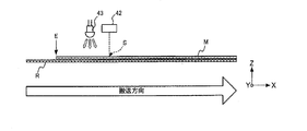
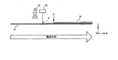
- 10A and 10B are diagrams showing the transport state of the print medium M and the ink ribbon R.
- the medium to be printed M has a release paper C.
- the surface of the release paper C on the side of the light sensor 42 has a color such as cream or light blue.
- the ink ribbon R has, for example, black, red and white.
- 10A is a state before the end E of the print medium M passes the detection position S on the transport path C by the light sensor 42, and the print medium M and the ink ribbon R are viewed from the width direction Y. It is a schematic diagram which shows a conveyance state.
- FIG. 10B is a schematic view showing the transport state of the print medium M and the ink ribbon R as viewed in the width direction Y after the end E of the print medium M has passed the detection position S by the optical sensor 42. It is.
- the light sensor 42 detects the color at the detection position S of the transport object
- the color information may be bright even when the light sensor 42 detects the brightness at the detection position S of the transport object
- the processing can be performed in the same way by simply replacing the information with the
- the tape end determination process a process of determining the presence or absence of the remaining amount of the print tape as the print medium M is performed.
- the printing apparatus 1 starts the tape end determination process shown in FIG. 9 based on the print start instruction.
- the processor 5 first operates the light sensor 42 before the medium to be printed M is transported, and acquires the RGB value of the detection signal detected by the light sensor 42 as an initial value (step S101).
- the end E of the printing medium M is upstream of the detection position S by the optical sensor 42 in the conveyance direction of the conveyance path C of the printing medium M positioned.
- the light sensor 42 faces the release paper C of the medium to be printed M, and the red value (R), the green value (G) and the red value corresponding to the color of the release paper C are An RGB value containing a blue value (B) is detected and sent to the processor 5 as a detection signal. Then, the processor 5 sets the red value (R), the green value (G) and the blue value (B) included in the RGB values of the detection signal sent from the light sensor 42 to initial values R before and G before , respectively. Acquire as B before and store in the RAM 7.
- the processor 5 turns on the thermal head 10 and turns on the stepping motor 12.
- the platen roller 21 rotates in the transport direction, transport of the print medium M starts, and printing on the print medium M is performed based on the print data.
- the processor 5 turns the thermal head 10 off and turns the stepping motor 12 off.
- the rotation of the platen roller 21 is stopped, the conveyance of the print medium M is ended, and the printing on the print medium M is ended (step S102).
- the processor 5 operates the light sensor 42 after the conveyance of the medium to be printed M is completed, and acquires the RGB value of the detection signal detected by the light sensor 42 (step S103).
- the end E of the print medium M is the transport path C of the print medium M.
- the light sensor 42 is positioned upstream of the detection position S by the light sensor 42. In this case, the print medium M and the ink ribbon R overlap with each other at the detection position S by the light sensor 42, and the light sensor 42 faces the release paper C of the print medium M.
- the light sensor 42 detects RGB values including a red value (R), a green value (G) and a blue value (B) corresponding to the color of the release paper C of the print medium M present at the detection position S , This is sent to the processor 5 as a detection signal. Then, after the conveyance of the print medium M, the processor 5 detects the red value (R), the green value (G) and the blue value (B) included in the RGB values of the detection signal sent from the light sensor 42 respectively.
- the RGB values R after , G after , and B after are acquired.
- the end E of the print medium M is the transport path C of the print medium M. In the transport direction, it is located downstream of the detection position S by the light sensor 42.
- the print medium M is not present at the detection position S by the light sensor 42, and only the ink ribbon R is present, and the light sensor 42 faces the ink ribbon R. Therefore, the light sensor 42 detects RGB values including a red value (R), a green value (G) and a blue value (B) corresponding to the color of the ink ribbon R present at the detection position S, and detects the RGB values As the processor 5.
- the processor 5 detects the red value (R), the green value (G) and the blue value (B) included in the RGB values of the detection signal sent from the light sensor 42 respectively.
- the RGB values R after , G after , and B after are acquired.
- the processor 5 detects the initial values (R before , G before , B before ) of RGB values detected by the light sensor 42 before the medium to be printed M is conveyed, and the light sensor 42 detects the initial values of the medium to be printed M It is determined whether or not there is a change in the RGB values (R after , G after , B after ) (step S104).
- the processor 5 calculates the initial values R before , G before and B before of the RGB values before conveyance of the medium to be printed M acquired in step S101 and the values of the medium to be printed M acquired in step S103. The rate of change of each of the transported RGB values R after , G after , and B after is determined.
- the processor 5 determines whether at least one of the red value (R), the green value (G) and the blue value (B) included in the RGB values has changed by a predetermined ratio (threshold) or more Determine Specifically, the processor 5 determines whether at least one of the red value (R), the green value (G) and the blue value (B) included in the RGB values has changed by a predetermined threshold or more. Determine if In the present embodiment, the threshold is set to, for example, 10%. The value of the threshold is not limited to this, and can be set to any ratio.
- the processor 5 determines whether at least one of the following (formula 1) to (formula 3) is satisfied.
- the processor 5 determines the RGB values acquired before and after the conveyance of the print medium M It is determined that the information on the color of the release paper C of the print medium M is indicated. In this case, the processor 5 determines that the end E of the print medium M has not yet passed on the transport path C, and the remaining amount of the print medium M still remains. When this process ends, the tape end determination process ends.
- the processor 5 determines the RGB values acquired after the conveyance of the print medium M It is determined that the color information of the ink ribbon R is indicated instead of the color information of the release paper C of the print medium M. That is, the processor 5 detects that the object to be conveyed at the detection position S has changed from the release paper C of the print medium M to the ink ribbon R based on the change in the color information detected by the light sensor 42 Thus, it is determined that the end E of the print medium M has passed the detection position S on the transport path C. If the processor 5 determines that the end E of the print medium M has passed the detection position S, it determines that the remaining amount of the print medium M is exhausted.
- the processor 5 determines that the remaining amount of the print medium M is exhausted based on the RGB values detected before and after the conveyance of the print medium M, for example, the display device 101 of the electronic device 100 loses the remaining amount of the print medium M The remaining amount of the print medium M is exhausted by displaying an error message to the effect or outputting a message sound indicating that the remaining amount of the print medium M is exhausted by a speaker (not shown) of the electronic device 100 or the like. Control to notify that is performed (step S105). Thus, the user can be clearly notified that the remaining amount of the print medium M has run out. Also, the processor 5 stops the operation of the printing apparatus 1 (step S106).
- the processor 5 temporarily stops the conveyance and printing operations of the printing apparatus 1 by stopping the supply of power to the thermal head 10 and the stepping motor 12 until the tape cassette 30 is replaced with another tape cassette 30. Do. Then, when the processor 5 is replaced with another tape cassette 30, the processor 5 releases the stop of the supply of power to the thermal head 10 and the stepping motor 12. When this process ends, the tape end determination process ends. As a result, when the remaining amount of the print medium M runs out, it is possible to prevent an idle run of the printing by the thermal head 10 in advance. Thereby, the components of the printing apparatus 1 such as the thermal head 10 and the platen roller 21 can be obtained. Can be protected.
- the printing apparatus 1 it is determined whether or not there is a remaining amount of the print medium M, based on the change in the color or the brightness of the transport object detected by the light sensor 42. Thus, it is possible to determine whether or not there is a remaining amount of the print medium M without applying any processing to the print medium M. In addition, since it is determined whether or not there is a remaining amount of the print medium M based on the difference in color information between the ink ribbon R and the print medium M, external light is transmitted to this determination. Also, it can be made less susceptible to environmental changes such as temperature changes.
- the print medium M since it is determined whether or not there is the remaining amount of the print medium M based on the change in color or brightness, any color or material in the relationship between the print medium M and the ink ribbon R, Even when a combination of structures is adopted, it can be determined whether or not there is a remaining amount of the print medium M. For example, even if the structure of the print medium M is a type that does not have the release paper C, the presence or absence of the remaining amount of the print medium M can be determined.
- the processor 5 detects the red value (R), the green value (G), and the RGB value including the blue value (B) detected by the light sensor 42.
- the presence or absence of the remaining amount of the print medium M is determined based on whether at least one of the values has changed by a predetermined ratio or more. Thereby, for example, even if the ink ribbon R and the print medium M have the same color, the presence or absence of the remaining amount of the print medium M can be determined.
- the light sensor 42 detects information on the color of the print medium M on the irradiation surface illuminated by the light source 43 and information on the color of the ink ribbon R. Therefore, even in a dark environment, the print medium M and the ink ribbon R can be distinguished and detected. Thereby, the determination accuracy of the presence or absence of the remaining amount of the print medium M can be improved. Further, since the print medium M and the ink ribbon R are formed of different materials, even if the colors of the print medium M and the ink ribbon R are similar, the reflectances are different from each other. Therefore, the print medium M and the ink ribbon R can be distinguished and detected based on the difference in brightness due to the difference in reflectance. Thereby, the determination accuracy of the presence or absence of the remaining amount of the print medium M can be improved.
- the processor 5 further includes information on the color detected by the light sensor 42 before the print medium M is conveyed, and information on the color detected by the light sensor 42 after the print medium M is conveyed. Based on the detection, the presence or absence of the remaining amount of the print medium M is detected. Therefore, since the detection interval by the light sensor 42 is relatively short, in the determination of the presence or absence of the remaining amount of the print medium M, the influence of environmental changes such as external light and temperature change on the light sensor 42 using a semiconductor Therefore, the determination accuracy of the presence or absence of the remaining amount of the print medium M can be improved. Further, in the prior art, in order to detect the end of the print medium, the identification mark formed on the print medium is detected, and for this purpose, it is necessary to continuously detect the identification mark.
- the detection by the light sensor 42 may be performed only twice before and after the medium to be printed M is transported. Therefore, it is possible to suppress the power consumption related to the determination of the presence or absence of the remaining amount of the print medium M, and to reduce the processing load on the processor 5.
- the processor 5 displays an error message on the display device 101 of the electronic device 100 in the above-described embodiment
- the present invention is not limited to this.
- the display device such as a display or a light emitting diode
- the processor 5 determines that the remaining amount of the print medium M is exhausted
- an error that the remaining amount of the print medium M is exhausted Control may be performed to display a message on the display device of the printing apparatus 1.
- the user can be clearly notified that the remaining amount of the print medium M has run out.
- the presence or absence of the remaining amount of the print medium M based on the information on the color or brightness of the print medium M detected by the light sensor 42 and the information on the color or brightness of the ink ribbon R
- the print medium M is created in a plurality of colors (for example, three colors) for each length, and information on the color or brightness of the print medium M (release paper C) which fluctuates for each length, and the ink ribbon R
- the presence or absence of the remaining amount of the print medium M may be determined based on the difference between the color or the brightness information.
- the processor 5 performs control to display a message according to the remaining amount.
- the light sensor 42 is disposed upstream of the thermal head 10 in the transport direction of the transport path C of the print medium M, but the present invention is not limited to this.
- the light sensor 42 may be disposed on the conveyance path C in which the print medium M and the ink ribbon R overlap and is conveyed, such as downstream of the thermal head 10.
- the processor 5 detects the information on the color or brightness detected by the light sensor 42 before the print medium M is conveyed and the light sensor 42 after the print medium M is conveyed.
- the example which determines the presence or absence of the residual amount of a to-be-printed medium based on the change of the color or brightness information was shown, it is not this limitation.
- the light sensor 42 detects color or brightness information continuously (for example, every one second) while the print medium M is transported, and the processor 5 detects the color or the brightness continuously detected. The presence or absence of the remaining amount of the print medium M may be determined on the basis of the difference in the size information.
- the processor 5 stops the conveyance of the printing apparatus 1 and the printing operation by stopping the supply of power to the thermal head 10 and the stepping motor 12. As a result, by preventing idle printing of the print by the thermal head 10, components of the printing apparatus 1 such as the thermal head 10 and the platen roller 21 can be protected. Furthermore, by preventing the useless operation of the printing apparatus 1, the power consumption of the printing apparatus 1 can be reduced.
- the processor 5 determines the initial values of the RGB values detected by the light sensor 42 before the conveyance of the print medium M, and the RGB values detected by the light sensor 42 after the conveyance of the print medium M ends.
- the processor 5 stores the RGB value detected only once as an initial value, and detects the initial value of the stored RGB value and the light sensor 42 after the conveyance of the print medium M is completed. It may be determined whether there is a change in the RGB values.
- the detection of the color or the brightness of the print medium by the light sensor 42 is performed from the print medium M side, but the present invention is not limited to this.
- the detection of the color or brightness of the print medium by the optical sensor 42 may be performed from the ink ribbon R side.
Landscapes
- Electronic Switches (AREA)
- Accessory Devices And Overall Control Thereof (AREA)
- Printers Characterized By Their Purpose (AREA)
- Handling Of Sheets (AREA)
- Handling Of Continuous Sheets Of Paper (AREA)
Abstract
This printing device is provided with: a processor that, on the basis of a detection result of detecting, from at least a one-side surface of a first member and a one-side surface of a second member, colors or brightnesses of a to-be-conveyed object conveyed in a state where a plurality of members are stacked, the plurality of members having the first member and the second member that have mutually different colors included in the respective areas of the respective one-side surfaces or have mutually different brightnesses in the respective areas of the respective one-side surfaces, detects one of the boundaries of the first member and the second member of the to-be-conveyed object, viewed from the respective one-side surfaces; and a print head that performs printing on at least a part of the to-be-conveyed object.
Description
本明細書は、印刷装置、印刷装置の印刷制御方法、及び、記録媒体に関する。
The present specification relates to a printing apparatus, a printing control method of the printing apparatus, and a recording medium.
従来、長尺状の被印刷媒体(印刷テープ)に文字等の印刷を行ってから切断することで、文字等が印刷された印刷テープ片(ラベル)を作成する印刷装置(ラベルプリンタ)及びこれに用いられる被印刷媒体を収納したテープカセットが知られている。
Conventionally, a printing apparatus (label printer) for producing a print tape piece (label) on which characters and the like are printed by printing characters and the like on a long print medium (print tape) and then cutting it There is known a tape cassette containing a print medium used for printing.
このような印刷装置において、テープカセット内の被印刷媒体の残量がなくなる前に、被印刷媒体に形成された識別マークを検出することで、被印刷媒体の終端を検出することができる機能を備えた印刷装置がある(例えば、日本国 特開2006-181829号公報 参照)。
In such a printing apparatus, the end of the print medium can be detected by detecting the identification mark formed on the print medium before the remaining amount of the print medium in the tape cassette is exhausted. There is a printing apparatus provided (see, for example, Japanese Patent Application Laid-Open No. 2006-181829).
しかしながら、特開2006-181829号公報に記載された技術を用いることで被印刷媒体の終端を検出できるものの、この技術を使用するためには被印刷媒体に対して識別マークを形成する加工をしなければならなかった。
However, although the end of the print medium can be detected by using the technology described in Japanese Patent Application Laid-Open No. 2006-181829, in order to use this technology, the identification mark is processed on the print medium. I had to.
以上のような実情を踏まえ、被印刷媒体を加工することなく、被印刷媒体の終端を検出することが望まれる。
It is desirable to detect the end of the print medium without processing the print medium based on the above-mentioned actual situation.
一態様に係る印刷装置は、少なくとも一方の面同士のそれぞれの領域に含まれる色が互いに異なる、又は、少なくとも一方の面同士のそれぞれの領域における明るさが互いに異なる第1部材及び第2部材を有する複数の部材が重ねられた状態で搬送される搬送対象物の前記色又は前記明るさを、前記少なくとも一方の面側から検出した検出結果に基づいて、前記少なくとも一方の面側から見た、前記搬送対象物の前記第1部材及び前記第2部材の一方の境界を検出するプロセッサと、前記搬送対象物の少なくとも一部に印刷を行う印刷ヘッドと、備える。
The printing apparatus according to one aspect includes a first member and a second member in which colors included in respective regions of at least one surface are different from each other, or brightness in respective regions of at least one surface is different from each other. The color or the brightness of the object to be conveyed which is conveyed in a state in which a plurality of members having a plurality of members are viewed from the at least one surface side based on the detection result detected from the at least one surface side The processor includes: a processor that detects a boundary of one of the first member and the second member of the transport object; and a print head that performs printing on at least a part of the transport object.
一態様に係る印刷装置の印刷制御方法によれば、前記印刷装置は、印刷を行う印刷ヘッドと、対象物の色又は明るさを検出する検出装置と、を備える。印刷制御方法は、少なくとも一方の面同士のそれぞれの領域に含まれる色が互いに異なる、又は、少なくとも一方の面同士のそれぞれの領域における明るさが互いに異なる第1部材及び第2部材を有する複数の部材が重ねられた状態で搬送される搬送対象物の色又は明るさを、前記検出装置により、前記少なくとも一方の面側から検出し、前記検出結果に基づいて、前記少なくとも一方の面側から見た、前記搬送対象物の前記第1部材及び前記第2部材の一方の境界を検出する。
According to a printing control method of a printing apparatus according to an aspect, the printing apparatus includes a print head that performs printing, and a detection device that detects a color or brightness of an object. The printing control method includes a plurality of first members and second members in which colors included in respective regions of at least one surface are different from each other, or brightness in respective regions of at least one surface is different from each other. The color or brightness of the object to be conveyed conveyed in a state in which the members are overlapped is detected from the at least one surface side by the detection device, and viewed from the at least one surface side based on the detection result. The boundary of one of the first member and the second member of the object to be conveyed is detected.
一態様に係る記録媒体は、印刷を行う印刷ヘッドを備えた印刷装置のコンピュータに、少なくとも一方の面同士のそれぞれの領域に含まれる色が互いに異なる、又は、少なくとも一方の面同士のそれぞれの領域における明るさが互いに異なる第1部材及び第2部材を有する複数の部材が重ねられた状態で搬送される搬送対象物の色又は明るさを、前記検出装置により、前記少なくとも一方の面側から検出させ、前記検出結果に基づいて、前記少なくとも一方の面側から見た、前記搬送対象物の前記第1部材及び前記第2部材の一方の境界を検出させる、処理を実行させる読み取り可能なプログラムを記録する。
A recording medium according to an aspect is a computer of a printing apparatus having a print head for printing, wherein colors included in respective areas of at least one side are different from each other, or respective areas of at least one side are different Detecting the color or brightness of the object to be conveyed conveyed in a state in which a plurality of members having first and second members different in brightness from each other are overlapped from the at least one surface side by the detection device A readable program for executing a process of causing one of the first member and the second member of the object to be transferred to be detected as viewed from the at least one surface based on the detection result Record.
図1は、本実施形態に係る印刷装置を含む印刷システムの構成を例示した図である。図2は、印刷装置の開閉蓋を開放した状態の斜視図である。図1に示す印刷システムは、印刷装置1と、印刷装置1へ印刷データを送信する電子機器100と、を含んでいる。印刷装置1と電子機器100は、無線通信又は有線通信でデータをやり取りする。
FIG. 1 is a diagram illustrating the configuration of a printing system including a printing apparatus according to the present embodiment. FIG. 2 is a perspective view of the printing apparatus with the open / close lid open. The printing system illustrated in FIG. 1 includes a printing device 1 and an electronic device 100 that transmits print data to the printing device 1. The printing apparatus 1 and the electronic device 100 exchange data by wireless communication or wired communication.
なお、本実施形態において、被印刷媒体M(印刷テープ)の搬送される方向を「搬送方向X」とし、この搬送方向Xに直交する被印刷媒体M(印刷テープ)の幅方向を「媒体幅方向Y」とし、被印刷媒体M(印刷テープ)の厚み方向を「厚み方向Z」とする。これらX方向、Y方向、及びZ方向は、互いに直交する。
In the present embodiment, the direction in which the printing medium M (printing tape) is transported is “conveying direction X”, and the width direction of the printing medium M (printing tape) orthogonal to the transporting direction X is “medium width The thickness direction of the print medium M (printing tape) is referred to as “thickness direction Z”. The X direction, the Y direction, and the Z direction are orthogonal to one another.
印刷装置1は、被印刷媒体に印刷を行うサーマルヘッド(印刷ヘッド)を備える印刷装置であり、例えば、長尺な帯状の被印刷媒体Mに、シングルパス方式で印刷を行うラベルプリンタである。図3は、印刷装置1に使用される被印刷媒体Mを媒体幅方向Yから見た断面図である。被印刷媒体Mは、例えば、粘着層Sを有する基材Bと、粘着層S(のり面)と、粘着層Sを覆う剥離可能な剥離紙Cと、を有する長尺状のテープ部材である。被印刷媒体Mは、剥離紙Cなしの長尺状のテープ部材であってもよい。
本実施形態では、基材Bの粘着層Sとは反対側の面(基材Bの表面。これを「印刷面P」とする。)に対しサーマルヘッド10により印刷が行われる。以降では、インクリボンを使用する熱転写方式のラベルプリンタを例にして説明するが、印刷方式は特に限定されない。本実施形態では、被印刷媒体(第2部材)Mと、インクリボン(第1部材)Rと、が重ねられた状態で、被印刷媒体MとインクリボンRの長さ方向が搬送経路に沿って搬送方向に搬送される。以下、被印刷媒体Mと、インクリボンRと、が重ねられた状態の搬送対象を区別しないときは単に搬送対象物ともいう。 Theprinting apparatus 1 is a printing apparatus provided with a thermal head (print head) for printing on a medium to be printed, and is, for example, a label printer for printing on a long strip-like medium to be printed M by a single pass method. FIG. 3 is a cross-sectional view of the print medium M used in the printing apparatus 1 as viewed in the medium width direction Y. The medium to be printed M is, for example, a long tape member having a base material B having a pressure-sensitive adhesive layer S, a pressure-sensitive adhesive layer S (stick surface), and a peelable release paper C covering the pressure-sensitive adhesive layer S. . The print medium M may be a long tape member without release paper C.
In the present embodiment, printing is performed by thethermal head 10 on the surface of the substrate B opposite to the adhesive layer S (the surface of the substrate B, which is referred to as “printed surface P”). Hereinafter, although a thermal transfer type label printer using an ink ribbon will be described as an example, the printing method is not particularly limited. In the present embodiment, in the state where the print-receiving medium (second member) M and the ink ribbon (first member) R are overlapped, the length direction of the print-receiving medium M and the ink ribbon R is along the transport path. And transported in the transport direction. Hereinafter, when not distinguishing the conveyance object of the state to which the to-be-printed medium M and the ink ribbon R were piled up, it also only says a conveyance object.
本実施形態では、基材Bの粘着層Sとは反対側の面(基材Bの表面。これを「印刷面P」とする。)に対しサーマルヘッド10により印刷が行われる。以降では、インクリボンを使用する熱転写方式のラベルプリンタを例にして説明するが、印刷方式は特に限定されない。本実施形態では、被印刷媒体(第2部材)Mと、インクリボン(第1部材)Rと、が重ねられた状態で、被印刷媒体MとインクリボンRの長さ方向が搬送経路に沿って搬送方向に搬送される。以下、被印刷媒体Mと、インクリボンRと、が重ねられた状態の搬送対象を区別しないときは単に搬送対象物ともいう。 The
In the present embodiment, printing is performed by the
印刷装置1は、図1、図2に示すように、印刷装置1は、装置筐体2と、この装置筐体2に開閉自在に取り付けられた開閉蓋3を備える。図2に示すように、装置筐体2は、内部にテープカセット30を収納するカセット収納部19を備えている。カセット収納部19の詳細については後述する。
装置筐体2の上面には、電源ボタン25の他、各種操作を行う操作ボタン26a,26b,26c(以下、「操作ボタン26」と呼ぶ)、開閉蓋3を開放させる蓋開閉ボタン27等が配置されている。
外部電源D(図8参照)が接続されている状態(すなわちACアダプタ接続状態)で電源ボタン25が押下されると、電源回路40(図8参照)に信号が送られて印刷装置1の電源がONになる。また、操作ボタン26や蓋開閉ボタン27が押下されると、プロセッサ5(図8参照)に信号が送られて、各ボタンに応じた処理が行われる。
また、図示しないが、装置筐体2には、電源コード接続端子、外部機器接続端子、記憶媒体挿入口等が設けられている。なお、印刷装置1が電池等の内部電源で動作するものである場合には、電源コード接続端子はなくてもよい。また、印刷装置1がパーソナルコンピュータや各種の端末装置等の外部機器との接続を行わずに使用できるものである場合や、外部機器と無線で接続可能に構成されている場合には、外部機器接続端子を備えていなくてもよい。 As shown in FIG. 1 and FIG. 2, theprinting apparatus 1 includes an apparatus housing 2 and an open / close lid 3 attached to the apparatus housing 2 so as to be openable and closable. As shown in FIG. 2, the device housing 2 is provided with a cassette storage portion 19 for storing the tape cassette 30 inside. Details of the cassette storage unit 19 will be described later.
In addition to thepower button 25, on the top surface of the device housing 2, operation buttons 26a, 26b, 26c (hereinafter referred to as "operation button 26") for performing various operations, a lid open / close button 27 for opening the open / close lid 3, etc. It is arranged.
When thepower button 25 is pressed in a state in which the external power source D (see FIG. 8) is connected (ie, AC adapter connected), a signal is sent to the power circuit 40 (see FIG. 8) to power the printing apparatus 1 Turns on. In addition, when the operation button 26 or the lid open / close button 27 is pressed, a signal is sent to the processor 5 (see FIG. 8), and processing corresponding to each button is performed.
Although not shown, the device housing 2 is provided with a power cord connection terminal, an external device connection terminal, a storage medium insertion slot, and the like. When theprinting apparatus 1 operates with an internal power supply such as a battery, the power supply cord connection terminal may be omitted. When the printing apparatus 1 can be used without connection with an external device such as a personal computer or various terminal devices, or when the printing device 1 is configured to be wirelessly connectable to an external device, the external device The connection terminal may not be provided.
装置筐体2の上面には、電源ボタン25の他、各種操作を行う操作ボタン26a,26b,26c(以下、「操作ボタン26」と呼ぶ)、開閉蓋3を開放させる蓋開閉ボタン27等が配置されている。
外部電源D(図8参照)が接続されている状態(すなわちACアダプタ接続状態)で電源ボタン25が押下されると、電源回路40(図8参照)に信号が送られて印刷装置1の電源がONになる。また、操作ボタン26や蓋開閉ボタン27が押下されると、プロセッサ5(図8参照)に信号が送られて、各ボタンに応じた処理が行われる。
また、図示しないが、装置筐体2には、電源コード接続端子、外部機器接続端子、記憶媒体挿入口等が設けられている。なお、印刷装置1が電池等の内部電源で動作するものである場合には、電源コード接続端子はなくてもよい。また、印刷装置1がパーソナルコンピュータや各種の端末装置等の外部機器との接続を行わずに使用できるものである場合や、外部機器と無線で接続可能に構成されている場合には、外部機器接続端子を備えていなくてもよい。 As shown in FIG. 1 and FIG. 2, the
In addition to the
When the
Although not shown, the device housing 2 is provided with a power cord connection terminal, an external device connection terminal, a storage medium insertion slot, and the like. When the
開閉蓋3は、カセット収納部19の上部を覆うように開閉可能に配置されている。開閉蓋3は、蓋開閉ボタン27が押下されることにより開放される。
また、開閉蓋3には、この開閉蓋3が閉じた状態でもカセット収納部19にテープカセット30(図4参照)が収納されているか否かを目視で確認可能とするために、窓3aが形成されている。
また、装置筐体2の側面であって、被印刷媒体Mの搬送方向Xの下流側に位置する部分には、排出口2aが形成されている。印刷装置1内でサーマルヘッド10による印刷が行われた被印刷媒体Mは、排出口2aから装置外へ排出される。 The open / close lid 3 is disposed to be openable and closable so as to cover the upper portion of thecassette storage unit 19. The open / close lid 3 is released by pressing the lid open / close button 27.
In addition, thewindow 3a is provided on the open / close lid 3 so that it can be visually confirmed whether the tape cassette 30 (see FIG. 4) is stored in the cassette storage portion 19 even when the open / close lid 3 is closed. It is formed.
Further, adischarge port 2 a is formed on the side surface of the apparatus housing 2 and on the downstream side in the transport direction X of the print medium M. The print medium M on which printing by the thermal head 10 has been performed in the printing apparatus 1 is discharged from the discharge port 2a to the outside of the apparatus.
また、開閉蓋3には、この開閉蓋3が閉じた状態でもカセット収納部19にテープカセット30(図4参照)が収納されているか否かを目視で確認可能とするために、窓3aが形成されている。
また、装置筐体2の側面であって、被印刷媒体Mの搬送方向Xの下流側に位置する部分には、排出口2aが形成されている。印刷装置1内でサーマルヘッド10による印刷が行われた被印刷媒体Mは、排出口2aから装置外へ排出される。 The open / close lid 3 is disposed to be openable and closable so as to cover the upper portion of the
In addition, the
Further, a
図4は、印刷装置1に収納されるテープカセット30の斜視図である。図5は、印刷装置1のカセット収納部19の斜視図である。図6は、印刷装置1の本実施形態に係る要部断面図である。図4に示すテープカセット30は、図5に示すカセット収納部19に着脱自在に収納される。図6には、テープカセット30がカセット収納部19に収納された状態が示されている。
FIG. 4 is a perspective view of the tape cassette 30 stored in the printing apparatus 1. FIG. 5 is a perspective view of the cassette storage unit 19 of the printing apparatus 1. FIG. 6 is a cross-sectional view of relevant parts of the printing apparatus 1 according to the present embodiment. The tape cassette 30 shown in FIG. 4 is detachably stored in the cassette storage unit 19 shown in FIG. FIG. 6 shows a state in which the tape cassette 30 is stored in the cassette storage unit 19.
テープカセット30は、図4に示すように、サーマルヘッド被挿入部36及び係合部37が形成された、被印刷媒体MとインクリボンRを収容するカセットケース31を有する。カセットケース31には、テープコア32とインクリボン供給コア34とインクリボン巻取りコア35が設けられている。被印刷媒体Mは、カセットケース31内部のテープコア32にロール状に巻かれている。また、熱転写用のインクリボンRは、その先端がインクリボン巻取りコア35に巻きつけられた状態で、カセットケース31内部のインクリボン供給コア34にロール状に巻かれている。
As shown in FIG. 4, the tape cassette 30 has a cassette case 31 in which the print medium M and the ink ribbon R are housed, in which the thermal head insertion portion 36 and the engagement portion 37 are formed. The cassette case 31 is provided with a tape core 32, an ink ribbon supply core 34, and an ink ribbon winding core 35. The print medium M is wound around the tape core 32 inside the cassette case 31 in a roll shape. The thermal transfer ink ribbon R is wound in a roll around the ink ribbon supply core 34 inside the cassette case 31 in a state where the tip thereof is wound around the ink ribbon winding core 35.
装置筐体2のカセット収納部19には、図5に示すように、テープカセット30を所定の位置で支持するための複数のカセット受け部20が設けられている。
As shown in FIG. 5, the cassette storage unit 19 of the apparatus housing 2 is provided with a plurality of cassette receiving units 20 for supporting the tape cassette 30 at a predetermined position.
カセット収納部19には、さらに、複数の発熱素子を有し、被印刷媒体Mに印刷を行うサーマルヘッド10と、被印刷媒体Mを搬送する搬送機構であるプラテンローラ21と、テープコア係合軸22と、インクリボン巻取り駆動軸23が設けられている。さらに、サーマルヘッド10には、サーミスタ13が埋め込まれている。サーミスタ13は、サーマルヘッド10の温度を測定するヘッド温度測定部である。
The cassette storage unit 19 further has a plurality of heat generating elements, and the thermal head 10 for printing on the print medium M, the platen roller 21 which is a transport mechanism for transporting the print medium M, and the tape core engaging shaft 22 and an ink ribbon winding drive shaft 23 are provided. Further, a thermistor 13 is embedded in the thermal head 10. The thermistor 13 is a head temperature measurement unit that measures the temperature of the thermal head 10.
カセット収納部19には、さらに、被印刷媒体Mの残量の有無の判断を行うための構成を有するテープエンド検出基板41が設けられている。図7A及び図7Bは、印刷装置1のテープエンド検出基板41の正面図である。図7Aに示すように、テープエンド検出基板41には、光センサ42と、光源43と、が設けられている。光センサ42は光を受光する受光領域42aを有している。光センサ42及び光源43が設けられたテープエンド検出基板41は、図7Bに示す被印刷媒体Mの搬送経路Cにおける搬送方向において、サーマルヘッド10の上流側に配置されている。従って、サーマルヘッド10により印刷が開始される前に、光センサ42により搬送対象物の色又は明るさを検出することにより、被印刷媒体Mの境界の一つである終端Eが光センサ42による検出位置Sを通過したか否か、すなわち、被印刷媒体Mの残量が無くなったか否かの判断を行うことができる。さらに、図7Bに示すように、光センサ42及び光源43は、搬送経路Cの搬送方向において、被印刷媒体M及びインクリボンRの媒体幅方向Yのほぼ中央と対向する位置に配置される。搬送対象物における光センサ42の受光領域42aと対向する領域が検出位置Sとなる。ここで、カセット収納部19は、被印刷媒体Mの幅が互いに異なる複数種類のテープカセット30を収納可能となっている。そして、被印刷媒体Mの幅が互いに異なる複数種類のテープカセット30の何れがカセット収納部19に収納された場合でも、被印刷媒体Mの媒体幅方向Yの中央はほぼ一定の位置になるように構成されている。これにより、被印刷媒体Mの幅が互いに異なる複数種類のテープカセット30のうちのどれがカセット収納部19に収納されても、被印刷媒体Mの媒体幅方向Yのほぼ中央と対向する位置に光センサ42及び光源43が配置されることになる。このため、被印刷媒体Mの幅によらず、被印刷媒体Mの残量の有無の判断を良好に行うことができる。
図6に示すように、光センサ42及び光源43が配置されたテープエンド検出基板41は、光センサ42及び光源43が被印刷媒体M(被印刷媒体Mが剥離紙Cを有している場合には剥離紙C、被印刷媒体Mが剥離紙Cを有していない場合には基材B)と対向する向きで、テープエンド検出基板41と被印刷媒体Mとの間隔が概ね所定の間隔(d1)となるように配置されている。本実施形態においては、間隔(d1)は、およそ5mm程度に設定されている。また、図7A及び図7Bに示すように、光センサ42と、光源43とは、所定の間隔(d2)をおいてテープエンド検出基板41上に配置されている。本実施形態においては、間隔(d2)は、およそ3mm程度に設定されている。 Thecassette storage unit 19 is further provided with a tape end detection substrate 41 having a configuration for determining the presence or absence of the remaining amount of the print medium M. 7A and 7B are front views of the tape end detection substrate 41 of the printing apparatus 1. As shown in FIG. 7A, the tape end detection substrate 41 is provided with an optical sensor 42 and a light source 43. The light sensor 42 has a light receiving area 42 a for receiving light. The tape end detection substrate 41 provided with the light sensor 42 and the light source 43 is disposed on the upstream side of the thermal head 10 in the transport direction on the transport path C of the print medium M shown in FIG. 7B. Therefore, before printing is started by the thermal head 10, the end E, which is one of the boundaries of the print medium M, is detected by the light sensor 42 by detecting the color or brightness of the conveyance object by the light sensor 42. Whether or not the detection position S has been passed, that is, whether or not the remaining amount of the print medium M is exhausted can be determined. Furthermore, as shown in FIG. 7B, the light sensor 42 and the light source 43 are disposed at positions facing substantially the center of the medium width direction Y of the print medium M and the ink ribbon R in the transport direction of the transport path C. An area facing the light receiving area 42 a of the light sensor 42 in the object to be conveyed is a detection position S. Here, the cassette storage unit 19 can store a plurality of types of tape cassettes 30 having different widths of the print medium M. Then, even when any of a plurality of types of tape cassettes 30 having different widths of the print medium M is stored in the cassette storage unit 19, the center in the medium width direction Y of the print medium M is substantially constant. Is configured. As a result, even if any of the plurality of types of tape cassettes 30 having different widths of the print medium M are stored in the cassette storage unit 19, the position is opposed to the approximate center of the medium width direction Y of the print medium M. The light sensor 42 and the light source 43 will be arranged. Therefore, regardless of the width of the print medium M, it is possible to properly determine the presence or absence of the remaining amount of the print medium M.
As shown in FIG. 6, in the tapeend detection substrate 41 on which the light sensor 42 and the light source 43 are disposed, the light sensor 42 and the light source 43 are the printing medium M (when the printing medium M has the release paper C In the case where the separation paper C and the printing medium M do not have the separation paper C, the distance between the tape end detection substrate 41 and the printing medium M is approximately predetermined in the direction facing the substrate B). It is arrange | positioned so that it may become (d1). In the present embodiment, the distance (d1) is set to about 5 mm. Further, as shown in FIGS. 7A and 7B, the light sensor 42 and the light source 43 are disposed on the tape end detection substrate 41 at a predetermined interval (d2). In the present embodiment, the distance (d2) is set to about 3 mm.
図6に示すように、光センサ42及び光源43が配置されたテープエンド検出基板41は、光センサ42及び光源43が被印刷媒体M(被印刷媒体Mが剥離紙Cを有している場合には剥離紙C、被印刷媒体Mが剥離紙Cを有していない場合には基材B)と対向する向きで、テープエンド検出基板41と被印刷媒体Mとの間隔が概ね所定の間隔(d1)となるように配置されている。本実施形態においては、間隔(d1)は、およそ5mm程度に設定されている。また、図7A及び図7Bに示すように、光センサ42と、光源43とは、所定の間隔(d2)をおいてテープエンド検出基板41上に配置されている。本実施形態においては、間隔(d2)は、およそ3mm程度に設定されている。 The
As shown in FIG. 6, in the tape
光源43は、例えば白色LEDにより形成され、光センサ42が搬送対象物の色又は明るさの検出を行う際に、搬送対象物に照明光を照射する。光源43は、光センサ42の感度特性に合わせて、光センサ42が検出可能な波長範囲を含む光を照射するものである。すなわち、光源43は、所望の波長範囲を含む光を照射することが可能なものであれば、白色LEDに限らず、例えば、赤色(R)、緑色(G)、青色(B)の3色のLEDにより構成されていてもよく、白熱電球でも、蛍光灯でもよい。
The light source 43 is formed of, for example, a white LED, and when the light sensor 42 detects the color or brightness of the object to be conveyed, it illuminates the object to be conveyed with illumination light. The light source 43 emits light including a wavelength range that can be detected by the light sensor 42 in accordance with the sensitivity characteristic of the light sensor 42. That is, the light source 43 is not limited to the white LED as long as the light source 43 can emit light including a desired wavelength range, and, for example, three colors of red (R), green (G), and blue (B) The light emitting diode may be constituted by an LED, or an incandescent lamp or a fluorescent lamp.
光センサ42は、受光領域42aと対向する位置にある搬送対象物の色又は明るさを検出する検出装置である。本実施形態において、検出対象物は被印刷媒体M又はインクリボンRであり、光センサ42は、被印刷媒体M(被印刷媒体Mが剥離紙Cを有している場合には剥離紙C、被印刷媒体Mが剥離紙Cを有していない場合には基材B)の色又は明るさと、インクリボンRの色又は明るさと、を検出することが可能である。光センサ42は、例えば、赤色値(R)、緑色値(G)及び青色値(B)の各色のフィルターを有するフォトダイオードを備えて構成されているカラーセンサである。この場合、光センサ42は、各フォトダイオードにより検出された光の強度を例えば16bitのデジタル値に変換して、RGB値とする。このため、光センサ42は、検出した光のスペクトルに応じたRGB値を有する色の情報を検出し、これを検出信号として出力する。これにより、光センサ42は、被印刷媒体Mの色と、インクリボンRの色と、が同系色であっても、それぞれの色に対して互いに異なるRGB値を検出することができる。光センサ42は、検出したRGB値を検出信号としてプロセッサ5へ送る。従って、プロセッサ5は、被印刷媒体Mの色と、インクリボンRの色と、が同系色であっても、光センサ42で検出された搬送対象物の色に対するRGB値の変化に基づいて、光センサ42の受光領域42aと対向する位置にある搬送対象物が、被印刷媒体MからインクリボンRに変わったと判断することができる。
The light sensor 42 is a detection device that detects the color or brightness of the object to be conveyed at a position facing the light receiving area 42 a. In the present embodiment, the detection target is the printing medium M or the ink ribbon R, and the light sensor 42 is the printing medium M (if the printing medium M has the release paper C, the release paper C, When the medium to be printed M does not have the release paper C, it is possible to detect the color or brightness of the substrate B) and the color or brightness of the ink ribbon R. The light sensor 42 is, for example, a color sensor configured to include a photodiode having filters of red color (R), green color (G) and blue color (B). In this case, the light sensor 42 converts the intensity of the light detected by each photodiode into, for example, a 16-bit digital value to obtain an RGB value. Therefore, the light sensor 42 detects color information having RGB values according to the detected light spectrum, and outputs this as a detection signal. Thereby, even if the color of the printing medium M and the color of the ink ribbon R are similar colors, the light sensor 42 can detect different RGB values for each color. The light sensor 42 sends the detected RGB values to the processor 5 as a detection signal. Therefore, even if the color of the printing medium M and the color of the ink ribbon R are similar colors, the processor 5 is based on the change of the RGB value for the color of the transport object detected by the light sensor 42. It can be determined that the object to be transported at the position facing the light receiving area 42 a of the light sensor 42 has changed from the print medium M to the ink ribbon R.
光センサ42は、搬送対象物の明るさを検出するものであってもよい。すなわち、光源43により照明されている照射面の反射率の違いによる明るさの違いを検出するものであってもよい。この場合、検出した明るさに基づいて、検出対象物が、被印刷媒体MからインクリボンRに変わったことを判断する。光センサ43は、カラーセンサの他、CCD(Charge-Coupled Device)イメージセンサ、CMOS(Complementary MOS)イメージセンサ、赤外線センサ等、搬送対象物である被印刷媒体Mの色又は明るさと、インクリボンRの色又は明るさとを識別できるセンサにより形成してもよい。
The light sensor 42 may detect the brightness of the object to be conveyed. That is, the difference in brightness due to the difference in reflectance of the illuminated surface illuminated by the light source 43 may be detected. In this case, based on the detected brightness, it is determined that the object to be detected has changed from the print medium M to the ink ribbon R. The light sensor 43 includes a color sensor, a CCD (Charge-Coupled Device) image sensor, a CMOS (Complementary MOS) image sensor, an infrared sensor, and the like, and the color or brightness of the print medium M as an object to be It may be formed by a sensor that can distinguish the color or brightness of the image.
テープカセット30がカセット収納部19に収納された状態では、図6に示すように、カセットケース31に設けられた係合部37がカセット収納部19に設けられたカセット受け部20に支持されて、サーマルヘッド10がカセットケース31に形成されたサーマルヘッド被挿入部36に挿入される。また、テープコア係合軸22には、テープカセット30のテープコア32が係合し、さらに、インクリボン巻取り駆動軸23には、インクリボン巻取りコア35が係合する。
In the state where the tape cassette 30 is stored in the cassette storage portion 19, as shown in FIG. 6, the engagement portion 37 provided in the cassette case 31 is supported by the cassette receiving portion 20 provided in the cassette storage portion 19. The thermal head 10 is inserted into a thermal head insertion portion 36 formed in the cassette case 31. Further, the tape core 32 of the tape cassette 30 is engaged with the tape core engagement shaft 22, and the ink ribbon take-up core 35 is engaged with the ink ribbon take-up drive shaft 23.
印刷装置1に印刷指示が入力されると、被印刷媒体Mは、プラテンローラ21の回転によりテープコア32から繰り出される。この際、インクリボン巻取り駆動軸23がプラテンローラ21に同調して回転することで、被印刷媒体MとともにインクリボンRがインクリボン供給コア34から繰り出される。これにより、被印刷媒体MとインクリボンRは重なった状態で搬送される。そして、サーマルヘッド10とプラテンローラ21の間を通過する際にインクリボンRがサーマルヘッド10によって加熱されることで、インクが被印刷媒体Mに転写され、印刷が行われる。
When a print instruction is input to the printing apparatus 1, the print medium M is fed out of the tape core 32 by the rotation of the platen roller 21. At this time, when the ink ribbon winding drive shaft 23 is rotated in synchronization with the platen roller 21, the ink ribbon R is fed out from the ink ribbon supply core 34 together with the print medium M. Thereby, the print medium M and the ink ribbon R are conveyed in an overlapping state. Then, when the ink ribbon R is heated by the thermal head 10 when passing between the thermal head 10 and the platen roller 21, the ink is transferred to the print medium M and printing is performed.
サーマルヘッド10とプラテンローラ21の間を通過した使用済みのインクリボンRは、インクリボン巻取りコア35に巻き取られる。一方、サーマルヘッド10とプラテンローラ21の間を通過した印刷済みの被印刷媒体Mは、ハーフカット装置16及びフルカット装置17で切断され、排出口2aから排出される。
なお、本実施形態においては、被印刷媒体Mの長さは、インクリボンRの長さよりも短く形成されている。そして、被印刷媒体Mの終端Eは、テープコア32に固定されていないため、被印刷媒体Mの終端Eは、最終的には光センサ42の前を通過して排出口2aから排出される。一方で、インクリボンRの両端は、インクリボン供給コア34及びインクリボン巻取りコア35に固定されているため、インクリボンRの終端は、テープカセット30の外に露呈することはなく、光センサ42の前を通過することもない。 The used ink ribbon R that has passed between thethermal head 10 and the platen roller 21 is wound around the ink ribbon winding core 35. On the other hand, the printed medium to be printed M which has passed between the thermal head 10 and the platen roller 21 is cut by the half cut device 16 and the full cut device 17 and discharged from the discharge port 2 a.
In the present embodiment, the length of the print medium M is shorter than the length of the ink ribbon R. Then, since the end E of the print medium M is not fixed to thetape core 32, the end E of the print medium M finally passes in front of the light sensor 42 and is discharged from the discharge port 2a. On the other hand, since both ends of the ink ribbon R are fixed to the ink ribbon supply core 34 and the ink ribbon take-up core 35, the end of the ink ribbon R is not exposed outside the tape cassette 30, and the light sensor There is no passing in front of 42.
なお、本実施形態においては、被印刷媒体Mの長さは、インクリボンRの長さよりも短く形成されている。そして、被印刷媒体Mの終端Eは、テープコア32に固定されていないため、被印刷媒体Mの終端Eは、最終的には光センサ42の前を通過して排出口2aから排出される。一方で、インクリボンRの両端は、インクリボン供給コア34及びインクリボン巻取りコア35に固定されているため、インクリボンRの終端は、テープカセット30の外に露呈することはなく、光センサ42の前を通過することもない。 The used ink ribbon R that has passed between the
In the present embodiment, the length of the print medium M is shorter than the length of the ink ribbon R. Then, since the end E of the print medium M is not fixed to the
本実施形態においては、光センサ42が配置されたテープエンド検出基板41は、カセット収納部19側に配置されている。従って、光センサ42による搬送対象物の色又は明るさの検出は、重なった状態で搬送される被印刷媒体MとインクリボンRのうち、被印刷媒体M側から行われる。
従って、被印刷媒体Mが残存している場合には、光センサ42は被印刷媒体M(被印刷媒体Mが剥離紙Cを有している場合には剥離紙C、被印刷媒体Mが剥離紙Cを有していない場合には基材B)の色又は明るさを検出する。そして、被印刷媒体Mが搬送されて、被印刷媒体Mの終端(境界)Eが光センサ42と対向する位置(検出位置S)を通過した後は、光センサ42はインクリボンRの色又は明るさを検出する。プロセッサ5は、光センサ42により検出された色又は明るさの変化に基づき、光センサ42による検出対象が被印刷媒体MからインクリボンRに変化したことを認識することで、被印刷媒体Mの終端Eが検出位置Sを通過して、被印刷媒体Mの残量が無くなったか否かを判断することができる。 In the present embodiment, the tapeend detection substrate 41 on which the light sensor 42 is disposed is disposed on the cassette storage unit 19 side. Therefore, the detection of the color or brightness of the object to be conveyed by the light sensor 42 is performed from the side of the medium to be printed M among the medium to be printed M and the ink ribbon R conveyed in the overlapping state.
Therefore, when the medium to be printed M remains, thelight sensor 42 separates the medium to be printed M (when the medium to be printed M has the release paper C, the release paper C and the medium to be printed M are peeled off) If the paper C is not present, the color or brightness of the substrate B) is detected. After the print medium M is conveyed and the end (boundary) E of the print medium M passes a position (detection position S) facing the light sensor 42, the light sensor 42 detects the color of the ink ribbon R or Detect the brightness. The processor 5 recognizes that the object to be detected by the light sensor 42 has changed from the medium to be printed M to the ink ribbon R on the basis of the change in color or brightness detected by the light sensor 42, whereby the medium 5 is printed. It can be determined whether the end E has passed the detection position S and the remaining amount of the print medium M has run out.
従って、被印刷媒体Mが残存している場合には、光センサ42は被印刷媒体M(被印刷媒体Mが剥離紙Cを有している場合には剥離紙C、被印刷媒体Mが剥離紙Cを有していない場合には基材B)の色又は明るさを検出する。そして、被印刷媒体Mが搬送されて、被印刷媒体Mの終端(境界)Eが光センサ42と対向する位置(検出位置S)を通過した後は、光センサ42はインクリボンRの色又は明るさを検出する。プロセッサ5は、光センサ42により検出された色又は明るさの変化に基づき、光センサ42による検出対象が被印刷媒体MからインクリボンRに変化したことを認識することで、被印刷媒体Mの終端Eが検出位置Sを通過して、被印刷媒体Mの残量が無くなったか否かを判断することができる。 In the present embodiment, the tape
Therefore, when the medium to be printed M remains, the
図8は、印刷装置1と電子機器100のハードウェア構成を示したブロック図である。印刷装置1は、上述のサーマルヘッド10、サーミスタ13、ハーフカット装置16、フルカット装置17、プラテンローラ21に加えて、プロセッサ5、ROM(Read Only Memory)6、RAM(Random Access Memory)7、通信インターフェース(IF)8、ヘッド駆動回路9、搬送用モータ駆動回路11、ステッピングモータ12、カッターモータ駆動回路14、カッターモータ15、及び、電源回路40を備える。なお、少なくともプロセッサ5、ROM6、及びRAM7は、印刷装置1のコンピュータを構成する。
FIG. 8 is a block diagram showing the hardware configuration of the printing apparatus 1 and the electronic device 100. As shown in FIG. The printing apparatus 1 includes a processor 5, a read only memory (ROM) 6, a random access memory (RAM) 7, in addition to the thermal head 10, the thermistor 13, the half cut device 16, the full cut device 17 and the platen roller 21 described above. A communication interface (IF) 8, a head drive circuit 9, a transport motor drive circuit 11, a stepping motor 12, a cutter motor drive circuit 14, a cutter motor 15, and a power supply circuit 40 are provided. At least the processor 5, the ROM 6, and the RAM 7 constitute a computer of the printing apparatus 1.
プロセッサ5は、例えばCPU(Central Processing Unit)などを含む。プロセッサ5は、ROM6に記憶されているプログラムをRAM7に展開し実行することで、印刷装置1の各部の動作を制御する。
The processor 5 includes, for example, a central processing unit (CPU). The processor 5 controls the operation of each unit of the printing apparatus 1 by developing the program stored in the ROM 6 in the RAM 7 and executing the program.
プロセッサ5は、例えば、制御信号(ストローブ信号、ラッチ信号、クロック信号)と印刷データをヘッド駆動回路9へ供給し、ヘッド駆動回路9を介してサーマルヘッド10を制御する。また、プロセッサ5は、モータ駆動回路(搬送用モータ駆動回路11、カッターモータ駆動回路14)を介してモータ(ステッピングモータ12、カッターモータ15)を制御する。
The processor 5 supplies, for example, control signals (strobe signals, latch signals, clock signals) and print data to the head drive circuit 9 and controls the thermal head 10 via the head drive circuit 9. The processor 5 also controls a motor (stepping motor 12 and cutter motor 15) via a motor drive circuit (transfer motor drive circuit 11 and cutter motor drive circuit 14).
プロセッサ5は、光センサ42で検出された搬送対象物の色又は明るさの変化に基づいて、被印刷媒体Mの終端Eが検出位置Sを通過したか否か、すなわち、被印刷媒体Mの残量があるか否かを判断する。具体的には、プロセッサ5は、光センサ42が搬送対象物の色を検出する場合、光センサ42により検出されたRGB値に含まれる赤色値(R)、緑色値(G)及び青色値(B)のうち、少なくとも1の値が所定の割合以上変化したか否かに基づいて、被印刷媒体Mの残量があるか否かを判断する。プロセッサ5は、光センサ42により検出される剥離紙Cの色の情報と、インクリボンRの色の情報と、に基づいて、被印刷媒体Mの終端Eが検出位置Sを通過したか否か、すなわち、残量があるか否かを判断する。従って、剥離紙Cがついた被印刷媒体Mの残量があるか否かを判断することができる。プロセッサ5による被印刷媒体Mの残量があるか否かの判断の詳細については後述する。
The processor 5 determines whether or not the end E of the print medium M has passed the detection position S based on the change in color or brightness of the transport object detected by the light sensor 42, ie, the print medium M Determine if there is a remaining amount. Specifically, when the light sensor 42 detects the color of the object to be transported, the processor 5 detects a red color (R), a green color (G), and a blue color (RGB values) included in the RGB values detected by the light sensor 42. Whether or not the remaining amount of the print medium M is present is determined based on whether or not the value of at least one of B) has changed by a predetermined ratio or more. The processor 5 determines whether the end E of the print medium M has passed the detection position S based on the information on the color of the release paper C detected by the light sensor 42 and the information on the color of the ink ribbon R That is, it is determined whether there is a remaining amount. Therefore, it can be determined whether there is the remaining amount of the printing medium M with the release paper C attached. Details of the determination as to whether or not there is a remaining amount of the print medium M by the processor 5 will be described later.
ROM6は、被印刷媒体Mに印刷を行う印刷プログラム、印刷プログラムの実行に必要な各種データ(例えば、フォント等)を記憶する。ROM6は、プロセッサ5によって読取り可能なプログラムが記憶された記憶媒体としても機能する。RAM7は、印刷内容のパターンを示すデータ(以降、印刷データと記す)を記憶する印刷データ記憶部を含む。さらに、RAM7は、表示データを記憶する表示データ記憶部を含む。通信インターフェース8は、有線通信又は無線通信により外部装置(例えば、電子機器100)との間でデータを授受する。
The ROM 6 stores a print program for printing on the print medium M, and various data (for example, fonts and the like) necessary for executing the print program. The ROM 6 also functions as a storage medium in which a program readable by the processor 5 is stored. The RAM 7 includes a print data storage unit that stores data (hereinafter referred to as print data) indicating a pattern of print content. Furthermore, the RAM 7 includes a display data storage unit that stores display data. The communication interface 8 exchanges data with an external device (for example, the electronic device 100) by wired communication or wireless communication.
ヘッド駆動回路9は、プロセッサ5から供給された制御信号と印刷データに基づいてサーマルヘッド10を駆動する。サーマルヘッド10は、主走査方向に配列された複数の発熱素子10aを有する印刷ヘッドである。ヘッド駆動回路9が、プロセッサ5から供給されたストローブ信号により指定される通電期間中に、ヘッド駆動回路9から出力された印刷データに応じて複数の発熱素子10aの何れかへ電流を選択的に流すことで、複数の発熱素子10aの何れかが発熱してインクリボンRを加熱する。これにより、サーマルヘッド10は、熱転写により被印刷媒体Mに1ラインずつ印刷を行う。即ち、印刷装置1は、サーマルラインプリンタである。
The head drive circuit 9 drives the thermal head 10 based on the control signal and print data supplied from the processor 5. The thermal head 10 is a print head having a plurality of heating elements 10 a arranged in the main scanning direction. The head drive circuit 9 selectively applies a current to any of the plurality of heating elements 10a in accordance with the print data output from the head drive circuit 9 during the conduction period specified by the strobe signal supplied from the processor 5. By flowing, one of the plurality of heating elements 10a generates heat to heat the ink ribbon R. Thereby, the thermal head 10 performs printing one line at a time on the print medium M by thermal transfer. That is, the printing apparatus 1 is a thermal line printer.
搬送用モータ駆動回路11は、ステッピングモータ12を駆動する。ステッピングモータ12は、プラテンローラ21を回転させる。プラテンローラ21は、ステッピングモータ12の動力によって回転し、被印刷媒体Mの長手方向(副走査方向)に被印刷媒体Mを搬送する搬送機構である。
The transport motor drive circuit 11 drives the stepping motor 12. The stepping motor 12 rotates the platen roller 21. The platen roller 21 is a transport mechanism that is rotated by the power of the stepping motor 12 and transports the print medium M in the longitudinal direction (sub scanning direction) of the print medium M.
カッターモータ駆動回路14は、カッターモータ15を駆動する。ハーフカット装置16及びフルカット装置17は、カッターモータ15の動力によって動作し、被印刷媒体Mをハーフカット又はフルカットする。フルカットとは、被印刷媒体Mの基材を剥離紙とともに幅方向に沿って切断する動作のことであり、ハーフカットは、基材のみを幅方向に沿って切断する動作のことである。電源回路40は、外部電源Dからの直流電圧(例えば、24V)から出力電圧を生成し、印刷装置1の各部に電力を供給する電源部である。
The cutter motor drive circuit 14 drives the cutter motor 15. The half cut device 16 and the full cut device 17 operate by the power of the cutter motor 15 to half cut or full cut the print medium M. The full cut is an operation of cutting the substrate of the printing medium M along the width direction together with the release paper, and the half cut is an operation of cutting only the substrate along the width direction. The power supply circuit 40 is a power supply unit that generates an output voltage from a DC voltage (for example, 24 V) from the external power supply D and supplies power to each unit of the printing apparatus 1.
電子機器100は、図1及び図8に示すように、表示装置101と入力装置102を備える、例えば、スマートフォン、タブレット端末などの携帯型のコンピュータである。表示装置101は、例えば、液晶ディスプレイであっても、有機エレクトロルミネッセンス(有機EL)ディスプレイであってもよい。入力装置102は、例えば、タッチパネルである。
As shown in FIGS. 1 and 8, the electronic device 100 is a portable computer, such as a smartphone or a tablet terminal, provided with a display device 101 and an input device 102. The display device 101 may be, for example, a liquid crystal display or an organic electroluminescent (organic EL) display. The input device 102 is, for example, a touch panel.
電子機器100は、上記の構成に加えて、表示駆動回路103、通信インターフェース(IF)104、ROM105、RAM106、プロセッサ107を備える。表示駆動回路103は、例えば、液晶表示ドライバ回路、有機EL表示ドライバ回路である。プロセッサ107は、演算部であり、アプリケーションプログラムを実行することで、印刷装置1から送られてきたエラーメッセージを表示装置101に表示する。
The electronic device 100 includes a display driving circuit 103, a communication interface (IF) 104, a ROM 105, a RAM 106, and a processor 107 in addition to the above-described configuration. The display drive circuit 103 is, for example, a liquid crystal display driver circuit or an organic EL display driver circuit. The processor 107 is an operation unit, and displays an error message sent from the printing apparatus 1 on the display device 101 by executing an application program.
図9は、テープエンド判断処理のフローチャートである。テープエンド判断処理について、図10A及び図10Bと併せて説明する。図10A及び図10Bは、被印刷媒体M及びインクリボンRの搬送状態を示す図である。ここで、被印刷媒体Mは剥離紙Cを有しているものとする。剥離紙Cは、例えば、少なくとも光センサ42側の面がクリーム色や水色等の色を有している。インクリボンRは、例えば、黒色、赤色、白色を有している。図10Aは、被印刷媒体Mの終端Eが光センサ42による、搬送経路C上の検出位置Sを通過する前の状態であって、被印刷媒体M及びインクリボンRを幅方向Yから見た搬送状態を示す模式図である。図10Bは、被印刷媒体Mの終端Eが光センサ42による検出位置Sを通過した後の状態であって、被印刷媒体M及びインクリボンRを幅方向Yから見た搬送状態を示す模式図である。以下では、光センサ42が搬送対象物の検出位置Sにおける色を検出する場合について説明するが、光センサ42が搬送対象物の検出位置Sにおける明るさを検出する場合も、色の情報を明るさの情報に置き換えるだけで、同様に処理を行うことができる。
FIG. 9 is a flowchart of the tape end determination process. The tape end determination process will be described in conjunction with FIGS. 10A and 10B. 10A and 10B are diagrams showing the transport state of the print medium M and the ink ribbon R. Here, it is assumed that the medium to be printed M has a release paper C. For example, at least the surface of the release paper C on the side of the light sensor 42 has a color such as cream or light blue. The ink ribbon R has, for example, black, red and white. 10A is a state before the end E of the print medium M passes the detection position S on the transport path C by the light sensor 42, and the print medium M and the ink ribbon R are viewed from the width direction Y. It is a schematic diagram which shows a conveyance state. FIG. 10B is a schematic view showing the transport state of the print medium M and the ink ribbon R as viewed in the width direction Y after the end E of the print medium M has passed the detection position S by the optical sensor 42. It is. Although the case where the light sensor 42 detects the color at the detection position S of the transport object will be described below, the color information may be bright even when the light sensor 42 detects the brightness at the detection position S of the transport object The processing can be performed in the same way by simply replacing the information with the
テープエンド判断処理では、被印刷媒体Mである印刷テープの残量の有無を判断する処理が行われる。印刷装置1は、印刷開始の指示に基づき、図9に示すテープエンド判断処理を開始する。テープエンド判断処理では、プロセッサ5は、まず、被印刷媒体Mの搬送前に光センサ42を動作させ、光センサ42で検出された検出信号のRGB値を初期値として取得する(ステップS101)。
被印刷媒体Mの搬送前においては、図10Aに示すように、被印刷媒体Mの終端Eは、被印刷媒体Mの搬送経路Cの搬送方向において、光センサ42による検出位置Sより上流側に位置している。従って、被印刷媒体Mの搬送前においては、光センサ42は被印刷媒体Mの剥離紙Cと対向しており、剥離紙Cの色に対応する赤色値(R)、緑色値(G)及び青色値(B)を含むRGB値を検出し、これを検出信号としてプロセッサ5へ送る。そして、プロセッサ5は、光センサ42から送られてきた検出信号のRGB値に含まれる赤色値(R)、緑色値(G)及び青色値(B)をそれぞれ、初期値Rbefore、Gbefore、Bbeforeとして取得し、RAM7に記憶する。 In the tape end determination process, a process of determining the presence or absence of the remaining amount of the print tape as the print medium M is performed. Theprinting apparatus 1 starts the tape end determination process shown in FIG. 9 based on the print start instruction. In the tape end determination process, the processor 5 first operates the light sensor 42 before the medium to be printed M is transported, and acquires the RGB value of the detection signal detected by the light sensor 42 as an initial value (step S101).
Before conveyance of the printing medium M, as shown in FIG. 10A, the end E of the printing medium M is upstream of the detection position S by theoptical sensor 42 in the conveyance direction of the conveyance path C of the printing medium M positioned. Therefore, before the medium to be printed M is transported, the light sensor 42 faces the release paper C of the medium to be printed M, and the red value (R), the green value (G) and the red value corresponding to the color of the release paper C are An RGB value containing a blue value (B) is detected and sent to the processor 5 as a detection signal. Then, the processor 5 sets the red value (R), the green value (G) and the blue value (B) included in the RGB values of the detection signal sent from the light sensor 42 to initial values R before and G before , respectively. Acquire as B before and store in the RAM 7.
被印刷媒体Mの搬送前においては、図10Aに示すように、被印刷媒体Mの終端Eは、被印刷媒体Mの搬送経路Cの搬送方向において、光センサ42による検出位置Sより上流側に位置している。従って、被印刷媒体Mの搬送前においては、光センサ42は被印刷媒体Mの剥離紙Cと対向しており、剥離紙Cの色に対応する赤色値(R)、緑色値(G)及び青色値(B)を含むRGB値を検出し、これを検出信号としてプロセッサ5へ送る。そして、プロセッサ5は、光センサ42から送られてきた検出信号のRGB値に含まれる赤色値(R)、緑色値(G)及び青色値(B)をそれぞれ、初期値Rbefore、Gbefore、Bbeforeとして取得し、RAM7に記憶する。 In the tape end determination process, a process of determining the presence or absence of the remaining amount of the print tape as the print medium M is performed. The
Before conveyance of the printing medium M, as shown in FIG. 10A, the end E of the printing medium M is upstream of the detection position S by the
そして、プロセッサ5は、サーマルヘッド10をONとし、ステッピングモータ12をONとする。これにより、プラテンローラ21が搬送方向に回転し、被印刷媒体Mの搬送が開始され、印刷データに基づいて被印刷媒体Mへの印刷が行われる。印刷データに基づく印刷が終了した場合には、プロセッサ5は、サーマルヘッド10をOFFとするとともに、ステッピングモータ12をOFFとする。これにより、プラテンローラ21の回転が停止し、被印刷媒体Mの搬送も終了し、被印刷媒体Mへの印刷も終了となる(ステップS102)。
Then, the processor 5 turns on the thermal head 10 and turns on the stepping motor 12. Thus, the platen roller 21 rotates in the transport direction, transport of the print medium M starts, and printing on the print medium M is performed based on the print data. When printing based on print data is completed, the processor 5 turns the thermal head 10 off and turns the stepping motor 12 off. Thus, the rotation of the platen roller 21 is stopped, the conveyance of the print medium M is ended, and the printing on the print medium M is ended (step S102).
被印刷媒体Mの搬送が終了すると、プロセッサ5は、被印刷媒体Mの搬送終了後に光センサ42を動作させ、光センサ42で検出された検出信号のRGB値を取得する(ステップS103)。
このとき、図10Aの場合と同様に、被印刷媒体Mの搬送後でも被印刷媒体Mがまだ残存している場合には、被印刷媒体Mの終端Eは、被印刷媒体Mの搬送経路Cの搬送方向において、光センサ42による検出位置Sより上流側に位置していることとなる。この場合、光センサ42による検出位置Sには、被印刷媒体MとインクリボンRが重なった状態で存在し、光センサ42は被印刷媒体Mの剥離紙Cと対向した状態になっている。そのため、光センサ42は、検出位置Sに存在する被印刷媒体Mの剥離紙Cの色に対応する赤色値(R)、緑色値(G)及び青色値(B)を含むRGB値を検出し、これを検出信号としてプロセッサ5へ送る。そして、プロセッサ5は、光センサ42から送られてきた検出信号のRGB値に含まれる赤色値(R)、緑色値(G)及び青色値(B)をそれぞれ、被印刷媒体Mの搬送終了後のRGB値Rafter,Gafter,Bafterとして取得する。 When the conveyance of the medium to be printed M is completed, theprocessor 5 operates the light sensor 42 after the conveyance of the medium to be printed M is completed, and acquires the RGB value of the detection signal detected by the light sensor 42 (step S103).
At this time, as in the case of FIG. 10A, when the print medium M still remains after the conveyance of the print medium M, the end E of the print medium M is the transport path C of the print medium M. In the conveyance direction, thelight sensor 42 is positioned upstream of the detection position S by the light sensor 42. In this case, the print medium M and the ink ribbon R overlap with each other at the detection position S by the light sensor 42, and the light sensor 42 faces the release paper C of the print medium M. Therefore, the light sensor 42 detects RGB values including a red value (R), a green value (G) and a blue value (B) corresponding to the color of the release paper C of the print medium M present at the detection position S , This is sent to the processor 5 as a detection signal. Then, after the conveyance of the print medium M, the processor 5 detects the red value (R), the green value (G) and the blue value (B) included in the RGB values of the detection signal sent from the light sensor 42 respectively. The RGB values R after , G after , and B after are acquired.
このとき、図10Aの場合と同様に、被印刷媒体Mの搬送後でも被印刷媒体Mがまだ残存している場合には、被印刷媒体Mの終端Eは、被印刷媒体Mの搬送経路Cの搬送方向において、光センサ42による検出位置Sより上流側に位置していることとなる。この場合、光センサ42による検出位置Sには、被印刷媒体MとインクリボンRが重なった状態で存在し、光センサ42は被印刷媒体Mの剥離紙Cと対向した状態になっている。そのため、光センサ42は、検出位置Sに存在する被印刷媒体Mの剥離紙Cの色に対応する赤色値(R)、緑色値(G)及び青色値(B)を含むRGB値を検出し、これを検出信号としてプロセッサ5へ送る。そして、プロセッサ5は、光センサ42から送られてきた検出信号のRGB値に含まれる赤色値(R)、緑色値(G)及び青色値(B)をそれぞれ、被印刷媒体Mの搬送終了後のRGB値Rafter,Gafter,Bafterとして取得する。 When the conveyance of the medium to be printed M is completed, the
At this time, as in the case of FIG. 10A, when the print medium M still remains after the conveyance of the print medium M, the end E of the print medium M is the transport path C of the print medium M. In the conveyance direction, the
これに対し、図10Bに示すように、被印刷媒体Mの搬送後に被印刷媒体Mの残量が無くなった場合には、被印刷媒体Mの終端Eは、被印刷媒体Mの搬送経路Cの搬送方向において、光センサ42による検出位置Sより下流側に位置することとなる。この場合、光センサ42による検出位置Sには、被印刷媒体Mは無く、インクリボンRのみが存在し、光センサ42はインクリボンRと対向した状態になる。そのため、光センサ42は、検出位置Sに存在するインクリボンRの色に対応する赤色値(R)、緑色値(G)及び青色値(B)を含むRGB値を検出し、これを検出信号としてプロセッサ5へ送る。そして、プロセッサ5は、光センサ42から送られてきた検出信号のRGB値に含まれる赤色値(R)、緑色値(G)及び青色値(B)をそれぞれ、被印刷媒体Mの搬送終了後のRGB値Rafter,Gafter,Bafterとして取得する。
On the other hand, as shown in FIG. 10B, when the remaining amount of the print medium M is exhausted after the conveyance of the print medium M, the end E of the print medium M is the transport path C of the print medium M. In the transport direction, it is located downstream of the detection position S by the light sensor 42. In this case, the print medium M is not present at the detection position S by the light sensor 42, and only the ink ribbon R is present, and the light sensor 42 faces the ink ribbon R. Therefore, the light sensor 42 detects RGB values including a red value (R), a green value (G) and a blue value (B) corresponding to the color of the ink ribbon R present at the detection position S, and detects the RGB values As the processor 5. Then, after the conveyance of the print medium M, the processor 5 detects the red value (R), the green value (G) and the blue value (B) included in the RGB values of the detection signal sent from the light sensor 42 respectively. The RGB values R after , G after , and B after are acquired.
次いで、プロセッサ5は、被印刷媒体Mの搬送前に光センサ42で検出したRGB値の初期値(Rbefore、Gbefore、Bbefore)と、被印刷媒体Mの搬送終了後に光センサ42で検出したRGB値(Rafter,Gafter,Bafter)と、に変化があるか否かを判定する(ステップS104)。
この処理では、プロセッサ5は、ステップS101で取得した被印刷媒体Mの搬送前のRGB値の初期値Rbefore,Gbefore,Bbeforeのそれぞれの値と、ステップS103で取得した被印刷媒体Mの搬送後のRGB値Rafter,Gafter,Bafterのそれぞれの値と、の変化の割合を判定する。すなわち、Rafterに対するRbeforeの変化の割合、Gafterに対するGbeforeの変化の割合、Bafterに対するBbeforeの変化の割合を判定する。
プロセッサ5は、RGB値に含まれる赤色値(R)、緑色値(G)及び青色値(B)のうちの、少なくともいずれか1つの値が、所定の割合(閾値)以上変化したか否かを判定する。具体的には、プロセッサ5は、RGB値に含まれる赤色値(R)、緑色値(G)及び青色値(B)のうちの、少なくともいずれか1つの値が所定の閾値以上変化したか否かを判定する。本実施形態においては、閾値は例えば10%に設定される。なお、閾値の値はこの限りではなく、任意の割合に設定することができる。
即ち、プロセッサ5は、下記(式1)~(式3)の少なくともいずれかが満たされているか否かを判定する。
(|Rafter-Rbefore|/Rbefore)≦0.1・・・(式1)
(|Gafter-Gbefore|/Gbefore)≦0.1・・・(式2)
(|Bafter-Bbefore|/Bbefore)≦0.1・・・(式3) Next, theprocessor 5 detects the initial values (R before , G before , B before ) of RGB values detected by the light sensor 42 before the medium to be printed M is conveyed, and the light sensor 42 detects the initial values of the medium to be printed M It is determined whether or not there is a change in the RGB values (R after , G after , B after ) (step S104).
In this process, theprocessor 5 calculates the initial values R before , G before and B before of the RGB values before conveyance of the medium to be printed M acquired in step S101 and the values of the medium to be printed M acquired in step S103. The rate of change of each of the transported RGB values R after , G after , and B after is determined. That is, the rate of change of R before to R after, the rate of change of G before to G after , and the rate of change of B before to B after are determined.
Theprocessor 5 determines whether at least one of the red value (R), the green value (G) and the blue value (B) included in the RGB values has changed by a predetermined ratio (threshold) or more Determine Specifically, the processor 5 determines whether at least one of the red value (R), the green value (G) and the blue value (B) included in the RGB values has changed by a predetermined threshold or more. Determine if In the present embodiment, the threshold is set to, for example, 10%. The value of the threshold is not limited to this, and can be set to any ratio.
That is, theprocessor 5 determines whether at least one of the following (formula 1) to (formula 3) is satisfied.
(| R after -R before | / R before ) ≦ 0.1 (Equation 1)
(| G after -G before | / G before ) ≦ 0.1 (Equation 2)
(| B after -B before | / B before ) ≦ 0.1 (Equation 3)
この処理では、プロセッサ5は、ステップS101で取得した被印刷媒体Mの搬送前のRGB値の初期値Rbefore,Gbefore,Bbeforeのそれぞれの値と、ステップS103で取得した被印刷媒体Mの搬送後のRGB値Rafter,Gafter,Bafterのそれぞれの値と、の変化の割合を判定する。すなわち、Rafterに対するRbeforeの変化の割合、Gafterに対するGbeforeの変化の割合、Bafterに対するBbeforeの変化の割合を判定する。
プロセッサ5は、RGB値に含まれる赤色値(R)、緑色値(G)及び青色値(B)のうちの、少なくともいずれか1つの値が、所定の割合(閾値)以上変化したか否かを判定する。具体的には、プロセッサ5は、RGB値に含まれる赤色値(R)、緑色値(G)及び青色値(B)のうちの、少なくともいずれか1つの値が所定の閾値以上変化したか否かを判定する。本実施形態においては、閾値は例えば10%に設定される。なお、閾値の値はこの限りではなく、任意の割合に設定することができる。
即ち、プロセッサ5は、下記(式1)~(式3)の少なくともいずれかが満たされているか否かを判定する。
(|Rafter-Rbefore|/Rbefore)≦0.1・・・(式1)
(|Gafter-Gbefore|/Gbefore)≦0.1・・・(式2)
(|Bafter-Bbefore|/Bbefore)≦0.1・・・(式3) Next, the
In this process, the
The
That is, the
(| R after -R before | / R before ) ≦ 0.1 (Equation 1)
(| G after -G before | / G before ) ≦ 0.1 (Equation 2)
(| B after -B before | / B before ) ≦ 0.1 (Equation 3)
被印刷媒体Mの搬送前後に取得したRGB値の間に閾値以上の変化がない場合(ステップS104のYES)には、プロセッサ5は、被印刷媒体Mの搬送前後で取得されたRGB値は被印刷媒体Mの剥離紙Cの色の情報を示していると判定する。この場合、プロセッサ5は、搬送経路C上を被印刷媒体Mの終端Eが未だ通過しておらず、まだ被印刷媒体Mの残量がまだあると判断する。この処理が終了すると、テープエンド判断処理は終了となる。
If there is no change equal to or greater than the threshold between the RGB values acquired before and after the conveyance of the print medium M (YES in step S104), the processor 5 determines the RGB values acquired before and after the conveyance of the print medium M It is determined that the information on the color of the release paper C of the print medium M is indicated. In this case, the processor 5 determines that the end E of the print medium M has not yet passed on the transport path C, and the remaining amount of the print medium M still remains. When this process ends, the tape end determination process ends.
これに対し、被印刷媒体Mの搬送前後に取得したRGB値の間に閾値以上の変化がある場合(ステップS104のNO)には、プロセッサ5は、被印刷媒体Mの搬送後に取得したRGB値は、被印刷媒体Mの剥離紙Cの色の情報を示しているのではなく、インクリボンRの色の情報を示していると判定する。即ち、プロセッサ5は、光センサ42により検出される色の情報が変化したことに基づいて、検出位置Sにおける搬送対象物が被印刷媒体Mの剥離紙CからインクリボンRに変化したことを検出し、これにより被印刷媒体Mの終端Eが搬送経路C上の検出位置Sを通過したと判断する。プロセッサ5は、被印刷媒体Mの終端Eが検出位置Sを通過したと判断すると、被印刷媒体Mの残量が無くなったと判断する。
On the other hand, when there is a change equal to or greater than the threshold between the RGB values acquired before and after the conveyance of the print medium M (NO in step S104), the processor 5 determines the RGB values acquired after the conveyance of the print medium M It is determined that the color information of the ink ribbon R is indicated instead of the color information of the release paper C of the print medium M. That is, the processor 5 detects that the object to be conveyed at the detection position S has changed from the release paper C of the print medium M to the ink ribbon R based on the change in the color information detected by the light sensor 42 Thus, it is determined that the end E of the print medium M has passed the detection position S on the transport path C. If the processor 5 determines that the end E of the print medium M has passed the detection position S, it determines that the remaining amount of the print medium M is exhausted.
プロセッサ5は、被印刷媒体Mの搬送前後に検出したRGB値に基づき被印刷媒体Mの残量が無くなったと判断すると、例えば、電子機器100の表示装置101に被印刷媒体Mの残量が無くなった旨のエラーメッセージを表示したり、電子機器100の図示しないスピーカ等により被印刷媒体Mの残量が無くなった旨のメッセージ音を出力したりして、被印刷媒体Mの残量が無くなったことを報知する制御を行う(ステップS105)。これにより、被印刷媒体Mの残量がなくなったことを利用者に明確に伝達することができる。
また、プロセッサ5は、印刷装置1の動作を停止させる(ステップS106)。この処理では、プロセッサ5は、別のテープカセット30に交換されるまで、サーマルヘッド10及びステッピングモータ12への電源の供給を停止することにより、印刷装置1の搬送及び印刷動作を一時的に停止する。そして、プロセッサ5は、別のテープカセット30に交換されると、サーマルヘッド10及びステッピングモータ12への電源の供給の停止を解除する。この処理が終了すると、テープエンド判断処理は終了となる。これにより、被印刷媒体Mの残量がなくなった場合に、サーマルヘッド10による印刷の空打ちを未然に防ぐことができるこれにより、サーマルヘッド10及びプラテンローラ21等の印刷装置1の構成部品を保護することができる。 If theprocessor 5 determines that the remaining amount of the print medium M is exhausted based on the RGB values detected before and after the conveyance of the print medium M, for example, the display device 101 of the electronic device 100 loses the remaining amount of the print medium M The remaining amount of the print medium M is exhausted by displaying an error message to the effect or outputting a message sound indicating that the remaining amount of the print medium M is exhausted by a speaker (not shown) of the electronic device 100 or the like. Control to notify that is performed (step S105). Thus, the user can be clearly notified that the remaining amount of the print medium M has run out.
Also, theprocessor 5 stops the operation of the printing apparatus 1 (step S106). In this process, the processor 5 temporarily stops the conveyance and printing operations of the printing apparatus 1 by stopping the supply of power to the thermal head 10 and the stepping motor 12 until the tape cassette 30 is replaced with another tape cassette 30. Do. Then, when the processor 5 is replaced with another tape cassette 30, the processor 5 releases the stop of the supply of power to the thermal head 10 and the stepping motor 12. When this process ends, the tape end determination process ends. As a result, when the remaining amount of the print medium M runs out, it is possible to prevent an idle run of the printing by the thermal head 10 in advance. Thereby, the components of the printing apparatus 1 such as the thermal head 10 and the platen roller 21 can be obtained. Can be protected.
また、プロセッサ5は、印刷装置1の動作を停止させる(ステップS106)。この処理では、プロセッサ5は、別のテープカセット30に交換されるまで、サーマルヘッド10及びステッピングモータ12への電源の供給を停止することにより、印刷装置1の搬送及び印刷動作を一時的に停止する。そして、プロセッサ5は、別のテープカセット30に交換されると、サーマルヘッド10及びステッピングモータ12への電源の供給の停止を解除する。この処理が終了すると、テープエンド判断処理は終了となる。これにより、被印刷媒体Mの残量がなくなった場合に、サーマルヘッド10による印刷の空打ちを未然に防ぐことができるこれにより、サーマルヘッド10及びプラテンローラ21等の印刷装置1の構成部品を保護することができる。 If the
Also, the
以上のように構成された印刷装置1では、光センサ42により検出される搬送対象物の色又は明るさの変化に基づいて、被印刷媒体Mの残量があるか否かを判断する。これにより、被印刷媒体M何らかの加工を加えることなく、被印刷媒体Mの残量があるか否かを判断することができる。また、インクリボンRと、被印刷媒体Mと、の色の情報の違いに基づいて被印刷媒体Mの残量があるか否かを判断しているため、この判断に対して、外部の光や、温度変化等の環境の変化の影響を受け難くすることができる。さらに、色や明るさの変化に基づいて被印刷媒体Mの残量があるか否かを判断しているため、被印刷媒体Mと、インクリボンRとの関係において、任意の色や素材、構造の組み合わせを採用した場合であっても、被印刷媒体Mの残量があるか否かを判断することができる。例えば、被印刷媒体Mの構造が剥離紙Cを有していないタイプであっても、被印刷媒体Mの残量の有無を判断することができる。
In the printing apparatus 1 configured as described above, it is determined whether or not there is a remaining amount of the print medium M, based on the change in the color or the brightness of the transport object detected by the light sensor 42. Thus, it is possible to determine whether or not there is a remaining amount of the print medium M without applying any processing to the print medium M. In addition, since it is determined whether or not there is a remaining amount of the print medium M based on the difference in color information between the ink ribbon R and the print medium M, external light is transmitted to this determination. Also, it can be made less susceptible to environmental changes such as temperature changes. Furthermore, since it is determined whether or not there is the remaining amount of the print medium M based on the change in color or brightness, any color or material in the relationship between the print medium M and the ink ribbon R, Even when a combination of structures is adopted, it can be determined whether or not there is a remaining amount of the print medium M. For example, even if the structure of the print medium M is a type that does not have the release paper C, the presence or absence of the remaining amount of the print medium M can be determined.
また、プロセッサ5は、光センサ42が色を検出するものである場合、光センサ42により検出された赤色値(R)、緑色値(G)及び青色値(B)を含むRGB値のうちの、少なくともいずれか1つの値が所定の割合以上変化したか否かに基づいて、被印刷媒体Mの残量の有無を判断している。これにより、例えばインクリボンRと被印刷媒体Mとが同系色であっても、被印刷媒体Mの残量の有無を判断することができる。
Further, when the light sensor 42 detects a color, the processor 5 detects the red value (R), the green value (G), and the RGB value including the blue value (B) detected by the light sensor 42. The presence or absence of the remaining amount of the print medium M is determined based on whether at least one of the values has changed by a predetermined ratio or more. Thereby, for example, even if the ink ribbon R and the print medium M have the same color, the presence or absence of the remaining amount of the print medium M can be determined.
また、光センサ42は、光源43により照射された照射面における被印刷媒体Mの色の情報と、インクリボンRの色の情報と、を検出する。従って、周囲が暗い環境下であっても、被印刷媒体MとインクリボンRとを区別して検出することができる。これにより、被印刷媒体Mの残量の有無の判断精度を向上させることができる。
また被印刷媒体Mと、インクリボンRと、はそれぞれ異なる材料により形成されているため、被印刷媒体MとインクリボンRの色が同系色であっても、相互に反射率は異なっている。そのため、反射率の違いによる明るさの違いにより被印刷媒体MとインクリボンRとを区別して検出することができる。これにより、被印刷媒体Mの残量の有無の判断精度を向上させることができる。 Further, thelight sensor 42 detects information on the color of the print medium M on the irradiation surface illuminated by the light source 43 and information on the color of the ink ribbon R. Therefore, even in a dark environment, the print medium M and the ink ribbon R can be distinguished and detected. Thereby, the determination accuracy of the presence or absence of the remaining amount of the print medium M can be improved.
Further, since the print medium M and the ink ribbon R are formed of different materials, even if the colors of the print medium M and the ink ribbon R are similar, the reflectances are different from each other. Therefore, the print medium M and the ink ribbon R can be distinguished and detected based on the difference in brightness due to the difference in reflectance. Thereby, the determination accuracy of the presence or absence of the remaining amount of the print medium M can be improved.
また被印刷媒体Mと、インクリボンRと、はそれぞれ異なる材料により形成されているため、被印刷媒体MとインクリボンRの色が同系色であっても、相互に反射率は異なっている。そのため、反射率の違いによる明るさの違いにより被印刷媒体MとインクリボンRとを区別して検出することができる。これにより、被印刷媒体Mの残量の有無の判断精度を向上させることができる。 Further, the
Further, since the print medium M and the ink ribbon R are formed of different materials, even if the colors of the print medium M and the ink ribbon R are similar, the reflectances are different from each other. Therefore, the print medium M and the ink ribbon R can be distinguished and detected based on the difference in brightness due to the difference in reflectance. Thereby, the determination accuracy of the presence or absence of the remaining amount of the print medium M can be improved.
また、プロセッサ5は、被印刷媒体Mが搬送される前に光センサ42により検出された色の情報と、被印刷媒体Mが搬送された後に光センサ42により検出された色の情報と、に基づき被印刷媒体Mの残量の有無を検出する。従って、光センサ42による検出間隔が比較的短いことから、被印刷媒体Mの残量の有無の判断において、外部の光や、半導体を使用する光センサ42に対する温度変化等の環境の変化の影響を受け難くすることができ、これにより、被印刷媒体Mの残量の有無の判断精度を向上させることができる。
また、従来技術では、被印刷媒体の終端を検出するために被印刷媒体に加工された識別マークを検出しており、そのために識別マークの検出を継続して行う必要があった。これに対し、本実施形態においては、被印刷媒体Mが搬送される前と後の2回だけ光センサ42による検出を行うだけで済む。このため、被印刷媒体Mの残量の有無の判断に関わる消費電力を押さえることができ、かつ、プロセッサ5の処理負担も軽減することができる。 In addition, theprocessor 5 further includes information on the color detected by the light sensor 42 before the print medium M is conveyed, and information on the color detected by the light sensor 42 after the print medium M is conveyed. Based on the detection, the presence or absence of the remaining amount of the print medium M is detected. Therefore, since the detection interval by the light sensor 42 is relatively short, in the determination of the presence or absence of the remaining amount of the print medium M, the influence of environmental changes such as external light and temperature change on the light sensor 42 using a semiconductor Therefore, the determination accuracy of the presence or absence of the remaining amount of the print medium M can be improved.
Further, in the prior art, in order to detect the end of the print medium, the identification mark formed on the print medium is detected, and for this purpose, it is necessary to continuously detect the identification mark. On the other hand, in the present embodiment, the detection by thelight sensor 42 may be performed only twice before and after the medium to be printed M is transported. Therefore, it is possible to suppress the power consumption related to the determination of the presence or absence of the remaining amount of the print medium M, and to reduce the processing load on the processor 5.
また、従来技術では、被印刷媒体の終端を検出するために被印刷媒体に加工された識別マークを検出しており、そのために識別マークの検出を継続して行う必要があった。これに対し、本実施形態においては、被印刷媒体Mが搬送される前と後の2回だけ光センサ42による検出を行うだけで済む。このため、被印刷媒体Mの残量の有無の判断に関わる消費電力を押さえることができ、かつ、プロセッサ5の処理負担も軽減することができる。 In addition, the
Further, in the prior art, in order to detect the end of the print medium, the identification mark formed on the print medium is detected, and for this purpose, it is necessary to continuously detect the identification mark. On the other hand, in the present embodiment, the detection by the
上述した実施形態は、発明の理解を容易にするために具体例を示したものであり、本発明はこれらの実施形態に限定されるものではない。印刷装置、印刷制御方法、及び、プログラムは、特許請求の範囲の記載を逸脱しない範囲において、さまざまな変形、変更が可能である。
The embodiments described above show specific examples to facilitate understanding of the invention, and the present invention is not limited to these embodiments. Various modifications and changes can be made to the printing apparatus, the printing control method, and the program without departing from the scope of the claims.
上述の実施形態においては、プロセッサ5は、電子機器100の表示装置101にエラーメッセージを表示しているがこの限りではない。例えば、印刷装置1にディスプレイや発光ダイオード等の表示装置を設け、プロセッサ5は、被印刷媒体Mの残量が無くなったと判断した場合には、被印刷媒体Mの残量が無くなった旨のエラーメッセージを印刷装置1の表示装置に表示する制御を行ってもよい。これにより、被印刷媒体Mの残量がなくなったことを利用者に明確に伝達することができる。
Although the processor 5 displays an error message on the display device 101 of the electronic device 100 in the above-described embodiment, the present invention is not limited to this. For example, when the display device such as a display or a light emitting diode is provided in the printing apparatus 1 and the processor 5 determines that the remaining amount of the print medium M is exhausted, an error that the remaining amount of the print medium M is exhausted Control may be performed to display a message on the display device of the printing apparatus 1. Thus, the user can be clearly notified that the remaining amount of the print medium M has run out.
上述した実施形態では、光センサ42により検出される被印刷媒体Mの色又は明るさの情報と、インクリボンRの色又は明るさの情報と、に基づいて被印刷媒体Mの残量の有無を判断する例を示したが、この限りではない。例えば、被印刷媒体Mを長さ毎に複数の色(例えば3色)で作成し、長さ毎に変動する被印刷媒体M(剥離紙C)の色又は明るさの情報と、インクリボンRの色又は明るさの情報と、の違いに基づいて被印刷媒体Mの残量の有無を判断してもよい。この場合、プロセッサ5は残量に応じたメッセージを表示する制御を行う。
In the embodiment described above, the presence or absence of the remaining amount of the print medium M based on the information on the color or brightness of the print medium M detected by the light sensor 42 and the information on the color or brightness of the ink ribbon R An example to judge the is shown, but it is not this limitation. For example, the print medium M is created in a plurality of colors (for example, three colors) for each length, and information on the color or brightness of the print medium M (release paper C) which fluctuates for each length, and the ink ribbon R The presence or absence of the remaining amount of the print medium M may be determined based on the difference between the color or the brightness information. In this case, the processor 5 performs control to display a message according to the remaining amount.
上述した実施形態では、光センサ42を、被印刷媒体Mの搬送経路Cの搬送方向において、サーマルヘッド10より上流側に配置する例を示したが、この限りではない。例えば、光センサ42を、サーマルヘッド10より下流側等、被印刷媒体MとインクリボンRとが重なった状態で搬送される搬送経路C上に配置してもよい。
In the embodiment described above, an example is shown in which the light sensor 42 is disposed upstream of the thermal head 10 in the transport direction of the transport path C of the print medium M, but the present invention is not limited to this. For example, the light sensor 42 may be disposed on the conveyance path C in which the print medium M and the ink ribbon R overlap and is conveyed, such as downstream of the thermal head 10.
上述した実施形態では、プロセッサ5は、被印刷媒体Mが搬送される前に光センサ42により検出された色又は明るさの情報と、被印刷媒体Mが搬送された後に光センサ42により検出された色又は明るさの情報と、の変化に基づき被印刷媒体の残量の有無を判断する例を示したが、この限りではない。例えば、光センサ42は、被印刷媒体Mが搬送される間は連続(例えば、1秒ごと)して色又は明るさの情報を検出し、プロセッサ5は、連続して検出される色又は明るさの情報の違いに基づき被印刷媒体Mの残量の有無を判断してもよい。被印刷媒体Mの残量が無くなったと判断した場合、プロセッサ5は、サーマルヘッド10及びステッピングモータ12への電源の供給を停止することにより、印刷装置1の搬送及び印刷動作を停止する。これにより、サーマルヘッド10による印刷の空打ちを未然に防ぐことで、サーマルヘッド10及びプラテンローラ21等の印刷装置1の構成部品を保護することができる。さらに、印刷装置1の無駄な動作を防ぐことで、印刷装置1の消費電力の低減を図ることができる。
In the embodiment described above, the processor 5 detects the information on the color or brightness detected by the light sensor 42 before the print medium M is conveyed and the light sensor 42 after the print medium M is conveyed. Although the example which determines the presence or absence of the residual amount of a to-be-printed medium based on the change of the color or brightness information was shown, it is not this limitation. For example, the light sensor 42 detects color or brightness information continuously (for example, every one second) while the print medium M is transported, and the processor 5 detects the color or the brightness continuously detected. The presence or absence of the remaining amount of the print medium M may be determined on the basis of the difference in the size information. If it is determined that the remaining amount of the print medium M has run out, the processor 5 stops the conveyance of the printing apparatus 1 and the printing operation by stopping the supply of power to the thermal head 10 and the stepping motor 12. As a result, by preventing idle printing of the print by the thermal head 10, components of the printing apparatus 1 such as the thermal head 10 and the platen roller 21 can be protected. Furthermore, by preventing the useless operation of the printing apparatus 1, the power consumption of the printing apparatus 1 can be reduced.
上述した実施形態では、プロセッサ5は、被印刷媒体Mの搬送前に光センサ42で検出したRGB値の初期値と、被印刷媒体Mの搬送終了後に光センサ42で検出したRGB値と、に変化があるか判定する例を示したが、この限りではない。例えば、プロセッサ5は、テープカセット30の交換時に、一度だけ検出したRGB値を初期値として記憶し、記憶しているRGB値の初期値と、被印刷媒体Mの搬送終了後に光センサ42で検出したRGB値と、に変化があるか判定してもよい。
In the embodiment described above, the processor 5 determines the initial values of the RGB values detected by the light sensor 42 before the conveyance of the print medium M, and the RGB values detected by the light sensor 42 after the conveyance of the print medium M ends. Although the example which determines whether there is a change was shown, it is not this limitation. For example, when replacing the tape cassette 30, the processor 5 stores the RGB value detected only once as an initial value, and detects the initial value of the stored RGB value and the light sensor 42 after the conveyance of the print medium M is completed. It may be determined whether there is a change in the RGB values.
上述した実施形態では、光センサ42による被印刷媒体の色又は明るさの検出は、被印刷媒体M側から行う例を示したが、この限りではない。例えば、被印刷媒体Mの長さを、インクリボンRの長さよりも長く形成した場合には、光センサ42による被印刷媒体の色又は明るさの検出は、インクリボンR側から行ってもよい。
In the embodiment described above, the detection of the color or the brightness of the print medium by the light sensor 42 is performed from the print medium M side, but the present invention is not limited to this. For example, when the length of the print medium M is longer than the length of the ink ribbon R, the detection of the color or brightness of the print medium by the optical sensor 42 may be performed from the ink ribbon R side. .
本願は、2017年6月26日に出願された日本国特許出願第2017-123918号に基づく優先権の利益を享受するものであり、その明細書、特許請求の範囲、図面及び要約書の全内容が、参照により、本明細書に組み込まれる。
This application claims the benefit of priority based on Japanese Patent Application No. 2017-123918 filed on Jun. 26, 2017, and the entire specification, claims, drawings, and abstract thereof. The contents are incorporated herein by reference.
Claims (14)
- 少なくとも一方の面同士のそれぞれの領域に含まれる色が互いに異なる、又は、少なくとも一方の面同士のそれぞれの領域における明るさが互いに異なる第1部材及び第2部材を有する複数の部材が重ねられた状態で搬送される搬送対象物の前記色又は前記明るさを、前記少なくとも一方の面側から検出した検出結果に基づいて、前記少なくとも一方の面側から見た、前記搬送対象物の前記第1部材及び前記第2部材の一方の境界を検出するプロセッサと、
前記搬送対象物の少なくとも一部に印刷を行う印刷ヘッドと、
を備える、印刷装置。 A plurality of members including a first member and a second member in which colors included in respective regions of at least one surface are different from each other, or brightness in respective regions of at least one surface is different from each other are overlapped. The first color of the transport object as viewed from the at least one surface side based on the detection result of detecting the color or the brightness of the transport object transported in the state from the at least one surface side A processor for detecting one of the boundaries between the member and the second member;
A print head that performs printing on at least a part of the transport target;
A printing device comprising: - 前記プロセッサは、前記搬送が行われる前に検出した第1の検出結果と、前記搬送が行われた後に検出した第2の検出結果との比較に基づいて、前記境界が検出位置を通過したか否かを判断することにより前記境界を検出する、請求項1に記載の印刷装置。 The processor determines whether the boundary passes the detection position based on a comparison between a first detection result detected before the transport is performed and a second detection result detected after the transport is performed. The printing apparatus according to claim 1, wherein the boundary is detected by determining whether or not it is not.
- 前記第1の検出結果及び前記第2の検出結果として、前記検出位置における前記搬送対象物の色の、赤色値(R)、緑色値(G)及び青色値(B)を含むRGB値を検出し、
前記プロセッサは、前記第1の検出結果及び前記第2の検出結果における、前記赤色値、前記緑色値及び前記青色値のうちの、少なくとも一つの値の比較に基づいて、前記境界が前記検出位置を通過したか否かを判断する、請求項2に記載の印刷装置。 As the first detection result and the second detection result, RGB values including the red value (R), the green value (G), and the blue value (B) of the color of the transport object at the detection position are detected And
The processor determines whether the boundary is the detection position based on comparison of at least one of the red value, the green value, and the blue value in the first detection result and the second detection result. The printing apparatus according to claim 2, wherein it is determined whether or not it has passed. - 前記搬送対象物は、前記第1部材の前記一方の面と前記第2部材の前記一方の面とが同じ向きで重ねられた状態で搬送される、請求項1に記載の印刷装置。 The printing apparatus according to claim 1, wherein the transport target is transported in a state in which the one surface of the first member and the one surface of the second member are overlapped in the same direction.
- 前記第1部材は、前記印刷ヘッドによる前記印刷に使用されるインクリボンであり、
前記第2部材は、前記印刷ヘッドにより前記印刷が行われる被印刷媒体である、請求項1に記載の印刷装置。 The first member is an ink ribbon used for the printing by the print head,
The printing apparatus according to claim 1, wherein the second member is a printing medium on which the printing is performed by the print head. - 前記被印刷媒体は、前記印刷ヘッドによる前記印刷が行われる印刷面を一方に有する長尺状の基材を有し、
前記被印刷媒体は前記インクリボンより短く、
前記搬送対象物は、前記被印刷媒体の残量があるときは、前記インクリボンが前記基材の前記印刷面側に重ねられた状態で搬送され、前記被印刷媒体の残量が無くなったときは、前記インクリボンが前記基材と重ならない状態で搬送され、
前記プロセッサは、前記基材の前記印刷面の反対側から前記搬送対象物の色又は明るさを検出した検出結果に基づいて、前記境界が検出位置を通過したと判断した場合に、前記被印刷媒体の残量が無くなったと判断する、請求項5に記載の印刷装置。 The printing medium has an elongated base having a printing surface on which the printing by the printing head is performed on one side,
The print medium is shorter than the ink ribbon,
When the transport target is transported in a state where the ink ribbon is overlapped on the printing surface side of the base when there is a remaining amount of the printing medium, when the remaining amount of the printing medium is exhausted Is transported with the ink ribbon not overlapping the substrate,
When the processor determines that the boundary has passed the detection position based on the detection result of detecting the color or brightness of the object to be transferred from the opposite side of the printing surface of the substrate, The printing apparatus according to claim 5, wherein it is determined that the remaining amount of the medium has run out. - 前記搬送対象物の前記色又は前記明るさを、前記少なくとも一方の面側から検出する検出装置を更に備え、
前記被印刷媒体は、前記基材の前記印刷面と反対側の面を、粘着層を介して覆う剥離紙を有し、
前記検出装置は、前記被印刷媒体の残量があるときは、前記剥離紙の前記検出装置側の色又は明るさを検出する、請求項6に記載の印刷装置。 It further comprises a detection device for detecting the color or the brightness of the object to be conveyed from the at least one surface side,
The print medium has a release paper that covers the surface of the base opposite to the print surface via an adhesive layer,
The printing apparatus according to claim 6, wherein the detection device detects a color or brightness of the release paper on the detection device side when there is a remaining amount of the printing medium. - 表示装置をさらに備え、
前記プロセッサは、前記第2部材の残量が無くなったと判断した場合に、前記第2部材の残量が無くなった旨を前記表示装置に表示する制御を実行する、請求項6に記載の印刷装置。 Further comprising a display device,
The printing apparatus according to claim 6, wherein the processor executes control to display on the display device that the remaining amount of the second member is exhausted when it is determined that the remaining amount of the second member is exhausted. . - 搬送経路に沿って前記被印刷媒体を搬送する搬送装置をさらに備え、
前記プロセッサは、前記第2部材の残量が無くなったと判断した場合には、前記搬送装置による搬送を停止させる制御を実行する、請求項6に記載の印刷装置。 The apparatus further comprises a transport device for transporting the print medium along the transport path,
The printing apparatus according to claim 6, wherein the processor executes control to stop the conveyance by the conveyance device when it is determined that the remaining amount of the second member is exhausted. - 前記搬送対象物の検出位置における色又は明るさを検出するときに、前記搬送対象物の前記検出位置を照明する照射装置をさらに備える、請求項1に記載の印刷装置。 The printing apparatus according to claim 1, further comprising: an irradiation device that illuminates the detection position of the transfer object when detecting a color or brightness at the detection position of the transfer object.
- 前記検出位置は、前記搬送対象物の搬送方向に直交する幅方向の中央となる位置に配置されている、請求項2に記載の印刷装置。 The printing apparatus according to claim 2, wherein the detection position is disposed at a center position in a width direction orthogonal to the transport direction of the transport target.
- 前記検出装置は、搬送経路において、前記印刷ヘッドに対して搬送方向における上流側に配置されている、請求項7に記載の印刷装置。 The printing apparatus according to claim 7, wherein the detection device is disposed upstream in the transport direction with respect to the print head in the transport path.
- 印刷装置の印刷制御方法であって、
前記印刷装置は、印刷を行う印刷ヘッドと、対象物の色又は明るさを検出する検出装置と、を備え、
少なくとも一方の面同士のそれぞれの領域に含まれる色が互いに異なる、又は、少なくとも一方の面同士のそれぞれの領域における明るさが互いに異なる第1部材及び第2部材を有する複数の部材が重ねられた状態で搬送される搬送対象物の色又は明るさを、前記検出装置により、前記少なくとも一方の面側から検出し、
前記検出結果に基づいて、前記少なくとも一方の面側から見た、前記搬送対象物の前記第1部材及び前記第2部材の一方の境界を検出する、印刷装置の印刷制御方法。 A printing control method of a printing apparatus
The printing apparatus includes a print head that performs printing, and a detection device that detects the color or brightness of an object.
A plurality of members including a first member and a second member in which colors included in respective regions of at least one surface are different from each other, or brightness in respective regions of at least one surface is different from each other are overlapped. Detecting the color or brightness of the object to be conveyed in the state from the at least one surface side by the detection device;
A printing control method for a printing apparatus, comprising: detecting a boundary of one of the first member and the second member of the object as viewed from the at least one surface based on the detection result. - 印刷を行う印刷ヘッドを備えた印刷装置のコンピュータに、
少なくとも一方の面同士のそれぞれの領域に含まれる色が互いに異なる、又は、少なくとも一方の面同士のそれぞれの領域における明るさが互いに異なる第1部材及び第2部材を有する複数の部材が重ねられた状態で搬送される搬送対象物の色又は明るさを、前記検出装置により、前記少なくとも一方の面側から検出させ、
前記検出結果に基づいて、前記少なくとも一方の面側から見た、前記搬送対象物の前記第1部材及び前記第2部材の一方の境界を検出させる、処理を実行させる読み取り可能なプログラムを記録した記録媒体。 A computer of a printing apparatus provided with a printing head for printing,
A plurality of members including a first member and a second member in which colors included in respective regions of at least one surface are different from each other, or brightness in respective regions of at least one surface is different from each other are overlapped. Causing the detection device to detect the color or brightness of the conveyance object conveyed in the state from the at least one surface side,
Based on the detection result, a readable program for executing a process for detecting the boundary of one of the first member and the second member of the transport object, as viewed from the at least one surface side, is recorded. recoding media.
Priority Applications (1)
| Application Number | Priority Date | Filing Date | Title |
|---|---|---|---|
| CN201880043026.0A CN110799340B (en) | 2017-06-26 | 2018-04-17 | Printing apparatus, printing control method, and recording medium |
Applications Claiming Priority (2)
| Application Number | Priority Date | Filing Date | Title |
|---|---|---|---|
| JP2017-123918 | 2017-06-26 | ||
| JP2017123918A JP7047266B2 (en) | 2017-06-26 | 2017-06-26 | Printing device, printing control method of printing device, and program |
Publications (1)
| Publication Number | Publication Date |
|---|---|
| WO2019003593A1 true WO2019003593A1 (en) | 2019-01-03 |
Family
ID=64741340
Family Applications (1)
| Application Number | Title | Priority Date | Filing Date |
|---|---|---|---|
| PCT/JP2018/015850 WO2019003593A1 (en) | 2017-06-26 | 2018-04-17 | Printing device, printing control method, and recording medium |
Country Status (3)
| Country | Link |
|---|---|
| JP (1) | JP7047266B2 (en) |
| CN (1) | CN110799340B (en) |
| WO (1) | WO2019003593A1 (en) |
Families Citing this family (2)
| Publication number | Priority date | Publication date | Assignee | Title |
|---|---|---|---|---|
| JP7367430B2 (en) | 2019-09-30 | 2023-10-24 | ブラザー工業株式会社 | printing device |
| CN116749658B (en) * | 2023-08-21 | 2023-11-14 | 武汉精臣智慧标识科技有限公司 | RFID label printer and read-write method thereof |
Citations (5)
| Publication number | Priority date | Publication date | Assignee | Title |
|---|---|---|---|---|
| JP2001146362A (en) * | 1999-11-19 | 2001-05-29 | Mitsubishi Paper Mills Ltd | Web cut detecting device in web manufacturing process |
| JP2005001887A (en) * | 2003-05-21 | 2005-01-06 | Seiko Epson Corp | Printer, control method and program of printer |
| JP2013075373A (en) * | 2011-09-29 | 2013-04-25 | Canon Inc | Recording device |
| JP2015063045A (en) * | 2013-09-24 | 2015-04-09 | カシオ計算機株式会社 | Printing device, printing method, program, and tape |
| JP2015066719A (en) * | 2013-09-27 | 2015-04-13 | セイコーエプソン株式会社 | Printer and method of controlling printer |
Family Cites Families (8)
| Publication number | Priority date | Publication date | Assignee | Title |
|---|---|---|---|---|
| JPS6083862A (en) * | 1983-10-17 | 1985-05-13 | Fuji Xerox Co Ltd | Multi-color transfer type thermal transfer printing apparatus |
| JPS61172480A (en) * | 1985-01-25 | 1986-08-04 | Matsushita Electric Ind Co Ltd | Multi-color heat transfer recording device |
| JPH08127167A (en) * | 1994-11-01 | 1996-05-21 | Arutetsuku Kk | Apparatus and method for detecting end of rolled sheet |
| JP2000071589A (en) * | 1998-06-16 | 2000-03-07 | Alps Electric Co Ltd | Ink ribbon assembly and heat transfer printer using this ink ribbon assembly |
| CN1319752C (en) * | 2003-05-21 | 2007-06-06 | 精工爱普生株式会社 | Printing device and its controlling method |
| JP2008009598A (en) * | 2006-06-28 | 2008-01-17 | Konica Minolta Business Technologies Inc | Print controller, print control program, and print control method |
| JP2011104828A (en) * | 2009-11-16 | 2011-06-02 | Canon Inc | Rolled recording medium and method for detecting final end of rolled recording medium |
| US9132674B2 (en) * | 2013-09-27 | 2015-09-15 | Seiko Epson Corporation | Printer and control method of a printer |
-
2017
- 2017-06-26 JP JP2017123918A patent/JP7047266B2/en active Active
-
2018
- 2018-04-17 WO PCT/JP2018/015850 patent/WO2019003593A1/en active Application Filing
- 2018-04-17 CN CN201880043026.0A patent/CN110799340B/en active Active
Patent Citations (5)
| Publication number | Priority date | Publication date | Assignee | Title |
|---|---|---|---|---|
| JP2001146362A (en) * | 1999-11-19 | 2001-05-29 | Mitsubishi Paper Mills Ltd | Web cut detecting device in web manufacturing process |
| JP2005001887A (en) * | 2003-05-21 | 2005-01-06 | Seiko Epson Corp | Printer, control method and program of printer |
| JP2013075373A (en) * | 2011-09-29 | 2013-04-25 | Canon Inc | Recording device |
| JP2015063045A (en) * | 2013-09-24 | 2015-04-09 | カシオ計算機株式会社 | Printing device, printing method, program, and tape |
| JP2015066719A (en) * | 2013-09-27 | 2015-04-13 | セイコーエプソン株式会社 | Printer and method of controlling printer |
Also Published As
| Publication number | Publication date |
|---|---|
| CN110799340A (en) | 2020-02-14 |
| JP2019006018A (en) | 2019-01-17 |
| CN110799340B (en) | 2021-09-14 |
| JP7047266B2 (en) | 2022-04-05 |
Similar Documents
| Publication | Publication Date | Title |
|---|---|---|
| CN109383140B (en) | Printing apparatus, printing control method, and recording medium | |
| US7938588B2 (en) | Thermal printer having first and second ring-like conveyance paths | |
| WO2019003593A1 (en) | Printing device, printing control method, and recording medium | |
| CN110014751A (en) | Printing equipment, printing control method and storage medium | |
| JP2014019049A (en) | Tape-shaped printing medium, tape cartridge, tape printing device, and method for controlling a tape printing device | |
| WO2013137216A1 (en) | Sensor level adjustment device for printer, and sensor level adjustment method | |
| JP7231088B2 (en) | PRINTING APPARATUS, PRINTING APPARATUS CONTROL METHOD, AND PROGRAM | |
| JP2613230B2 (en) | Thermal transfer recording device | |
| EP3521045B1 (en) | Printer and printer control method | |
| JP2001322329A (en) | Recorder | |
| JP2014061603A (en) | Printing device and printing control method for printing device | |
| JP7024363B2 (en) | Printing device, control method of printing device, and program | |
| JP4581894B2 (en) | Thermal transfer printer | |
| JPS60257282A (en) | Image-forming device | |
| JP2007307860A (en) | Printer apparatus and ink sheet therefor | |
| JP2001080182A (en) | Ink ribbon and ink ribbon detector | |
| JP2004322405A (en) | Ink ribbon | |
| JP2022049160A (en) | Image forming device | |
| JP2017080983A (en) | Thermal transfer type printer | |
| JPH11157159A (en) | Printer | |
| JPS6260679A (en) | Thermal transfer recorder | |
| JP2003285567A (en) | Ink ribbon sheet set, ink ribbon cassette and printing device | |
| KR20000047089A (en) | Device for elevating and dropping thermal transfer head | |
| JPH1120284A (en) | Printing device | |
| JPH11321053A (en) | Printer |
Legal Events
| Date | Code | Title | Description |
|---|---|---|---|
| 121 | Ep: the epo has been informed by wipo that ep was designated in this application |
Ref document number: 18823803 Country of ref document: EP Kind code of ref document: A1 |
|
| NENP | Non-entry into the national phase |
Ref country code: DE |
|
| 122 | Ep: pct application non-entry in european phase |
Ref document number: 18823803 Country of ref document: EP Kind code of ref document: A1 |