WO2018235692A1 - 留め具 - Google Patents
留め具 Download PDFInfo
- Publication number
- WO2018235692A1 WO2018235692A1 PCT/JP2018/022561 JP2018022561W WO2018235692A1 WO 2018235692 A1 WO2018235692 A1 WO 2018235692A1 JP 2018022561 W JP2018022561 W JP 2018022561W WO 2018235692 A1 WO2018235692 A1 WO 2018235692A1
- Authority
- WO
- WIPO (PCT)
- Prior art keywords
- leg
- pair
- axial direction
- grommet
- ribs
- Prior art date
- Legal status (The legal status is an assumption and is not a legal conclusion. Google has not performed a legal analysis and makes no representation as to the accuracy of the status listed.)
- Ceased
Links
Images



Classifications
-
- F—MECHANICAL ENGINEERING; LIGHTING; HEATING; WEAPONS; BLASTING
- F16—ENGINEERING ELEMENTS AND UNITS; GENERAL MEASURES FOR PRODUCING AND MAINTAINING EFFECTIVE FUNCTIONING OF MACHINES OR INSTALLATIONS; THERMAL INSULATION IN GENERAL
- F16B—DEVICES FOR FASTENING OR SECURING CONSTRUCTIONAL ELEMENTS OR MACHINE PARTS TOGETHER, e.g. NAILS, BOLTS, CIRCLIPS, CLAMPS, CLIPS OR WEDGES; JOINTS OR JOINTING
- F16B19/00—Bolts without screw-thread; Pins, including deformable elements; Rivets
Definitions
- the present invention relates to a fastener that is inserted into and attached to a mounting hole.
- a mounting hole is formed in a vehicle body panel or the like of an automobile, and a fastener (2-piece clip) consisting of a grommet and a pin member may be used when mounting a vehicle component in the mounting hole.
- a fastener (2-piece clip) consisting of a grommet and a pin member
- the grommet is inserted into the mounting hole, and the locking portion formed on the outer periphery of the grommet is engaged with the back peripheral edge of the mounting hole, and the pin member is inserted into the grommet in that state.
- the fixing force can be improved by suppressing the diameter reduction of the part.
- an engagement protrusion with which the pin member is engaged is formed.
- a trim board etc. are attached to a vehicle body panel etc. using such a fastener.
- a fastener consisting of a grommet and a pin member
- a flange portion disposed on the front side of the mounting hole, a leg portion extended from the back surface side of the flange portion, and a leg outer periphery
- a fastener comprising a grommet having an engagement pawl on the back side periphery of the mounting hole and a pin having a head and a shaft.
- a pair of engaging portions are provided in a protruding manner on the inner side of the leg portion of the grommet, and a constricted engaging recess is formed on the outer periphery of the shaft portion of the pin. Then, when the shaft of the pin is inserted into the leg of the grommet, the pair of engaging portions is engaged with the engaging recess, and the pin is held by the grommet in a retaining manner.
- the grommet as described above When the grommet as described above is molded, the molten resin is filled in the mold, and then the mold is cut out from the outer periphery or the inner periphery of the leg portion.
- the grommet in the fastener of Patent Document 1 has a pair of engaging portions protruding from the inside of the leg, when the pullout pin forming the inner shape of the leg is pulled out of the leg, the forming pin is In order to catch on the pair of engaging portions, the mold is pulled out in a so-called forced removal state in which the legs are pulled out and the mold is released.
- the deformation of the leg may reduce the engagement of the engaging claw provided on the outer periphery of the leg with respect to the rear side peripheral edge of the mounting hole, which is required for the grommet There is a possibility that a predetermined removal force (a holding force for preventing removal from the mounting hole) can not be obtained.
- an object of the present invention is to suppress deformation of the leg portion when forcibly removing the inner shape of the leg portion, and to suppress reduction in the engagement of the locking portion with the peripheral edge on the back side of the mounting hole. It is possible to provide a fastener.
- the present invention is a fastener which is inserted into and attached to a mounting hole, and includes a head disposed on the front side of the mounting hole, and a bottomed cylindrical member extending from the head. And a pin member inserted into the leg portion of the grommet, the leg portion being provided on the outer surface of the grommet, and at least a pair of the leg portions being engaged with the back peripheral edge of the mounting hole And a pair of engaging projections provided on the inner surface and engaged with the pin member, wherein the inner surface of the leg is seen from the axial direction of the leg, A pair of first ribs extending in the axial direction is provided at a position not overlapping the pair of engaging projections with the axial center of the leg interposed therebetween.
- the inner surface of the leg when viewed from the axial direction of the leg, the inner surface of the leg extends axially in a position not overlapping the pair of engaging projections with the axial center of the leg interposed therebetween. Since the pair of first ribs is provided, the pin-like form which forms the internal shape of the leg portion is provided with the pair of engaging projections of the leg portion when it is forcibly pulled out from the inner side of the leg portion. Even if the non-place is deformed, after the pin-shaped mold is removed, the pair of first ribs makes it easy to return the deformed part to the original shape, and the deformation of the leg can be suppressed. As a result, it is possible to suppress a decrease in the amount of engagement of at least a pair of locking portions with the back side peripheral edge of the mounting hole.
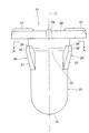
- FIG. 1 shows an embodiment of a fastener according to the present invention, and is a perspective view of a grommet and a pin member that is inserted into the grommet and retained. It is a front view of the grommet which comprises the fastener.
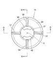
- FIG. 3 is a cross-sectional view taken along the line AA in FIG. 2 (a cross-sectional view when the leg is viewed from the axial direction). It is a top view of the same grommet.
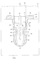
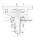
- FIG. 5 is a cross-sectional view taken along line BB in FIG. 4; FIG. 5 is a cross-sectional view taken along a line DD in FIG.
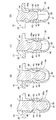
- FIG. 6C is an explanatory view showing a third state
- FIG. 6D is an explanatory view showing a fourth state.
- the fastener 10 is inserted into and attached to a mounting hole 3 formed in a predetermined member, and a head 20 disposed on the front side of the mounting hole 3, and the head A grommet 15 having a bottomed cylindrical leg portion 30 extending from the portion 20; and a pin member 60 inserted into the leg portion 30 of the grommet 15 and held by the grommet 15 and held therein.
- the fastener 10 of this embodiment is adapted to be inserted into and attached to a circular attachment hole 3 formed in the mounting member 1 as shown in FIGS. 7 and 8.
- the mounting member 5 is fixed to the mounting member 1 via the mounting member 1.
- Examples of the mounting member 1 include a car body panel and a car body frame.
- Examples of the mounting member 5 include electric components such as a trim board, a cover, a garnish, an assist grip, a bumper, and a lamp Materials, etc., but not limited thereto.
- the grommet 15 which comprises the fastener 10 has the bottomed cylindrical-shaped leg part 30, when attaching an electrically-wired part, such as a lamp, to a panel in the location where a watertight structure is required, for example Can be suitably used.
- the mounting seat 7 of the mounting member 5 has a frame shape with the locking groove 8 formed at the bottom, and holds the head 61 of the pin member 60 described later. It is possible. However, for example, a circular insertion hole may be provided in the mounting member 5 and the head portion 20 of the grommet 15 may be engaged with the front side, and there is no particular limitation.
- occlusion etc. sin-called hole plug
- the “back side of the mounting hole” in the present invention is one side portion in the thickness direction of the member (here, the mounting member 1) in which the mounting hole is formed, and the head disposition side of the grommet 15 It means the other side.
- the head portion 20 in this embodiment is in the form of a substantially annular thin walled flange having a circular opening 21 at its center.
- the shape of this head is not limited to the said aspect, What is necessary is just a shape which can be arrange
- a cushion member 70 made of a soft material such as a sponge is disposed on the back side of the head 20, but this cushion member 70 is not provided. It is good.
- a bottomed cylindrical leg 30 extends from the back side of the head 20.
- the leg 30 of this embodiment extends from the back side peripheral edge of the opening 21 of the head 20 so as to form a substantially cylindrical shape and
- the direction along the axis C of the leg 30 means the same as in the following description), and the tip end side is closed by the rounded bottom 31 in an arc shape.
- the outer surface of the leg 30 in the axial direction has a tapered shape in which the diameter gradually decreases toward the axial distal end side (meaning the bottom 31 side. The same applies to the following description).
- the step portion 33 is formed, and the axial direction distal end side of the leg portion 30 has a smaller diameter than the axial direction proximal end side through the step portion 33.
- each locking portion 35 is disposed at a position where the top 36 protruding most from the outer surface of the leg 30 is substantially aligned with the step 33 of the leg 30.
- a tapered surface 37 is formed which gradually reduces in diameter from the top portion 36 of each locking portion 35 toward the tip end side in the axial direction of the leg 30, and further, opposite to the tapered surface 37 of each locking portion 35.
- a locking step 38 perpendicular to the axial direction of the leg 30 is formed.
- At least one pair of locking portions may be provided, and two or more pairs may be provided.
- the pair of locking portions may not be disposed at locations facing in the circumferential direction of the outer surface of the leg 30.
- shape and position of the locking portion are not limited to the above embodiment, and can be appropriately selected according to the thickness and shape of the mounting member provided with the mounting hole, the purpose of use of the fastener, etc. .
- a pair of engagement projections 40, 40 that engage with the pin member 60 are provided on the inner surface of the leg 30, a pair of engagement projections 40, 40 that engage with the pin member 60 are provided.
- the pair of locking portions 35, 35 and the pair of engagement protrusions 40, 40 are provided at positions not overlapping when viewed from the axial direction of the leg 30. It is done.
- the inner surface of the leg 30 when viewed from the axial direction of the leg 30, the inner surface of the leg 30 is opposed in the circumferential direction so as to be orthogonal to the pair of locking portions 35, 35.
- a pair of engagement projections 40, 40 are provided at the places.
- each engaging projection 40 has a shape protruding from the inner surface of the leg 30 so as to form a substantially chevron when viewed from a cross section along the axial direction of the leg 30. ing. Specifically, it has a tip side slope 42 whose height gradually decreases toward the axial direction tip side of the leg 30 from the top 41 projecting the highest from the inner surface of the leg 30 and the top 41 There is a proximal end slope 43 whose height gradually decreases toward the axial proximal end side of the leg 30. Furthermore, as shown in FIG. 3 and FIG. 4, each of the substantially mountain-shaped engaging projections 40 has an arc shape along the inner circumferential direction of the leg 30 when viewed from the axial direction of the leg 30. It is formed in a predetermined width, and the circumferential direction both side parts have a shape in which the inner surface side of the leg 30 is wide and the width is gradually narrowed toward the axial center C of the leg 30.
- the inner surface on the tip end side in the axial direction of the leg portion 30 continues to the pair of engaging projections 40 and gradually in the inner diameter toward the tip end side in the axial direction of the leg portion 30
- a projection 44 is provided which projects in the direction.
- the protrusion 44 of this embodiment extends from the lowest height portion of the tip end side slope 42 of each engagement protrusion 40 and, as shown in FIG.
- the leg 30 is provided so as to gradually narrow in width toward the tip end side in the axial direction of the leg 30.
- the shape and the position of the pair of engaging projections are not particularly limited, and may be appropriately selected according to the shape of the pin member 60 held by the grommet and the purpose of use of the grommet. Can.
- the pair of first ribs 50, 50 align with the circumferentially central portion of the pair of locking portions 35, 35. It arrange
- the pair of first ribs 50, 50 face the circumferential direction of the inner surface of the leg 30 so as to be orthogonal to the pair of engagement projections 40, 40. It is arranged at the place where the
- the pair of first ribs 50, 50 extends from the inner peripheral edge of the opening 21 of the head 20 along the thickness direction of the head 20 and the axial direction of the legs 30.
- the tip end in the extension direction is formed so as to extend beyond the top 41 and the tip side slope 42 of the engagement projection 40 to a substantially central position in the axial direction of the projection 44.
- the pair of first ribs is not limited to the above-described arrangement location, and viewed from the axial direction of the leg 30, the pair of engagement projections 40, with the axial center C of the leg 30 interposed therebetween.
- the shape of the pair of first ribs is not particularly limited as long as it is disposed so as not to overlap with 40.
- each first rib 50 has a height from the opening 21 of the head 20 to the step 33 of the leg 30 with respect to the protruding height of the leg 30 in the inner diameter direction,
- the protruding height of the portion from the step portion 33 of the leg portion 30 to the tip end in the axial direction with respect to the inner diameter direction of the leg portion 30 is formed small, whereby the distance between the pair of first ribs 50 is constant.
- a pair of engaging protrusions 40 is formed on the inner surface on the axial proximal end side of the leg 30.
- a pair of second ribs 55, 55 is provided at a position overlapping with 40.
- the pair of second ribs 55, 55 are aligned with the circumferentially central portion of the pair of engagement protrusions 40, 40. It arrange
- the pair of second ribs 55, 55 are orthogonal to the pair of locking portions 35, 35 and the pair of first ribs 50, 50, It arrange
- the pair of second ribs 55, 55 extends from the inner peripheral edge of the opening 21 of the head 20 along the thickness direction of the head 20 and the axial direction of the legs 30.
- the distal end portion in the extension direction is connected to the proximal end slope 43 of the engagement protrusion 40.
- a pair of 2nd ribs are not limited to the arrangement
- the shape of the pair of second ribs is not particularly limited.
- a plurality of projections are provided on the front side of the head 20 and from the peripheral edge of the opening 21. That is, from the front side peripheral edge of the opening portion 21, the pair of first protrusions 57, 57 is a location facing the circumferential direction of the head portion 20 so as to be aligned with the pair of first ribs 50, 50.
- the head portion 20 extends in the outer radial direction, and the base end portions thereof are respectively connected to the axial base end portions of the pair of first ribs 50, 50.
- a pair of second protrusions 59, 59 are provided from the peripheral edge on the front side of the opening 21 at a location facing in the circumferential direction of the head 20 so as to be aligned with the pair of second ribs 55, 55.
- the head portion 20 extends in the outer radial direction, and the base end portions thereof are respectively connected to the axially base end portions of the pair of second ribs 55, 55.
- Each of the first projections 57 and the second projections 59 has a pair of left and right slopes, and has a peak shape with a pointed peak shape, so that it is easy to bite into the cushion member 70 disposed on the back side of the head 20. Thus, the cushion member 70 can be prevented from rotating and positioned.
- the pair of first ribs 50, 50 and the pair of second ribs 55, 55 are arranged to be orthogonal to each other when viewed from the axial direction of the leg 30.
- the pin member 60 which is inserted into the leg portion 30 of the grommet 15 and retained and retained will be described. As shown in FIGS. 1, 7 and 8, the pin member 60 extends from the back side of the head 61 and a head 61 engaged with the frame-like mounting seat 7 formed on the mounting member 5. And an axial portion 63.
- the head 61 is connected to a neck 61a inserted into the locking groove 8 formed in the bottom of the mounting seat 7 and an upper end of the neck 61a, and a disc engaged with the front side peripheral edge of the locking groove 8 Disc-shaped pin flange connected to the lower end of the neck portion 61a and engaged with the back side peripheral edge of the locking groove 8 and in contact with the surface side of the head 20 of the grommet 15 And a portion 61c.
- the shaft portion 63 extends in a cylindrical shape with a predetermined length from the center on the back side of the pin flange portion 61c, and a recessed portion 65 narrowed in a predetermined shape is formed on the outer periphery in the axial direction. Further, the distal end portion 67 of the axial portion 63 in the axial direction is such that the outer periphery thereof gradually reduces in diameter toward the distal end in the axial direction, and the tip end is rounded. A stop portion 67a is formed. Then, the pair of engaging projections 40 and 40 of the grommet 15 enter the recess 65, and the locking step portion 67a of the tip portion 67 of the pin member 60 is locked to the tip side slope 42 thereof. The pin member 60 is retained and held in the leg portion 30 of the grommet 15 (see FIG. 7).
- the shape of the pin member is not particularly limited as long as it is a shape that is engaged with the pair of engaging protrusions in a state where it is inserted into the leg of the grommet and retained from the leg of the grommet .
- the material of the grommet 15 and the pin member 60 which consist of the said structure can be formed with resin materials, such as polyamide-type resin, such as nylon, polyacetal (POM), a polypropylene (PP), for example.
- resin materials such as polyamide-type resin, such as nylon, polyacetal (POM), a polypropylene (PP), for example.
- the resin material may be formed of a fiber reinforced resin which is reinforced by containing glass fiber, carbon fiber, metal fiber and the like.
- the neck portion 61a of the pin member 60 is inserted into the locking groove 8 of the mounting seat 7 formed in the mounting member 5, and the mounting flange portion 61b and the pin flange portion 61c are engaged with the front and back peripheral edges of the locking groove 8. Then, as shown in FIG. 7 and FIG. 8, the head 61 of the pin member 60 is attached to the attachment seat 7.
- the leg portion 30 of the grommet 15 is inserted into the mounting hole 3 formed in the mounting member 1 from the tip end side in the axial direction, and the cushion member 70 disposed on the back side of the head 20 is mounted in the mounting hole By elastically contacting the front side peripheral edge of 3 and by engaging the respective engaging steps 38, 38 of the pair of engaging portions 35, 35 of the leg 30 on the back side peripheral edge of the mounting hole 3, The grommet 15 can be attached to the attachment hole 3 (see FIG. 8).
- the shaft 63 of the pin member 60 is inserted into the leg 30 through the opening 21 of the grommet 15. Then, the pair of engagement projections 40 and 40 in the leg 30 enter the recess 65 of the pin member 60 and the engagement of the tip end portion 67 of the pin member 60 on the tip side slope 42 of each engagement projection 40 The step portion 67a is engaged, and further, the pin flange portion 61c of the pin member 60 abuts on the front side of the head portion 20 of the grommet 15, and as shown in FIG. The pin member 60 is retained and held. As a result, as shown in FIG. 7 and FIG. 8, the mounting member 5 can be attached to the mounting member 1 via the fastener 10 composed of the grommet 15 and the pin member 60.
- the grommet 15 of this embodiment is formed, for example, as follows. That is, as shown in FIG. 3, the back sides of the outer peripheral shape of the leg portion 30 of the grommet 15 and the outer peripheral shape of the head portion 20 are mainly separated in the direction orthogonal to the axial direction of the leg portion 30 It is molded by the first mold 81 and the second mold 82 which slide in the direction. Further, as shown in FIG. 5, the front side of the outer peripheral shape of the head portion 20 of the grommet 15 is formed by a third mold 83 that slides along the axial direction of the leg 30.
- a pin-shaped fourth mold 84 that slides along the axial direction of the leg 30 is disposed inside the third mold 83.
- the fourth mold 84 has a shape corresponding to the inner peripheral shape of the leg 30, and has a tip 85 provided with a diameter-increased portion 85a having a diameter-increased diameter. doing.
- the fourth form 84 slides along the axial direction of the leg 30 and is forcibly pulled out, whereby the grommet 15 is formed.
- the inner circumferential shape of the head portion 20 and the leg portion 30 is formed.
- the cavity defined in the mold is filled with the melted resin by injection molding or the like.
- the grommet 15 is formed.
- the first mold 81 and the second mold 82 are moved so as to be away from each other, and the mold is removed.
- the pin-shaped fourth mold 84 is pulled out from the inside of the leg 30 in a forcedly removed state.
- the enlarged diameter portion 85a of the tip end portion 85 of the fourth form 84 is caught on the tip side slopes 42, 42 of the pair of engagement projections 40, 40, and the leg Push the part 30 apart.
- the fourth form 84 is pulled out, as shown in FIG. 9B, the enlarged diameter portion 85a of the tip end portion 85 abuts on the top portions 41, 41 of the pair of engagement projections 40, 40. , And further spread the pair of engagement projections 40, 40.
- This state is the state in which the leg 30 is most deformed.
- the leading end 85 of the fourth mold 84 is caught on the pair of engagement projections 40, 40, and the force is pulled out.
- the portion of the leg 30 where the pair of engaging projections 40 and 40 are provided is deformed so as to spread outward, while the pair of engaging projections 40 of the leg 30 is The portions not provided with 40 tend to be deformed so as to be recessed inward.
- the fastener 10 as shown in FIG. 3, on the inner surface of the leg 30 of the grommet 15, as viewed from the axial direction of the leg 30, the axial center C of the leg 30 is sandwiched. Since the pair of first ribs 50, 50 extending in the axial direction are provided at positions not overlapping the engaging projections 40, 40, as described above, the fourth form 84 can not be inserted from the inside of the leg 30. Even when the portion where the pair of engaging projections 40, 40 of the leg 30 is not deformed when being extracted, the state shown in FIG. 9D after the fourth form 84 is removed.
- the deformed portion When it has become, the deformed portion can be easily returned to the original shape by the pair of first ribs 50, 50, and the deformation of the leg 30 can be suppressed. As a result, it is possible to suppress a reduction in the amount of engagement of the pair of locking portions 35, 35 with respect to the back side peripheral edge of the mounting hole 3, and the fastener 10 can be fixed to the mounting hole 3 by a predetermined removal force (from the mounting hole It can be mounted firmly so as to obtain a holding force).
- the inner surface on the proximal end side in the axial direction of the leg 30 is located at a position overlapping the pair of engagement projections 40 when viewed from the axial direction of the leg 30.
- a pair of second ribs 55, 55 are provided.
- the pin-shaped fourth mold frame 84 is forcibly pulled out from the inside of the leg 30, even if the portion where the pair of engagement projections 40, 40 of the leg 30 is provided is deformed, the fourth After the mold of the formwork 84 is removed, the deformed portions can be easily returned to the original shape by the pair of second ribs 55, 55, and the engagement of the pair of locking portions 35, 35 with respect to the back side peripheral edge of the mounting hole 3 It is possible to secure enough. In addition, secure sufficiently the engagement margin between the engagement protrusion 40 and the pin member 60 (here, the engagement margin of the locking step portion 67a of the pin member 60 with respect to the tip side slope 42 of the engagement protrusion 40). Thus, the retaining force of the pin member 60 against the leg 30 of the grommet 15 can be enhanced.
- the pair of locking portions 35, 35 and the pair of engagement projections 40, 40 are in a position where they do not overlap when viewed from the axial direction of the leg 30. It is provided. Therefore, when the pin-shaped fourth mold frame 84 is forcibly removed from the inside of the leg 30, the leg 30 can be easily deformed, and the fourth mold 84 can be easily removed. The deformed portion of the leg 30 can be easily returned to the original shape by the pair of first ribs 50, 50 and the pair of second ribs 55, 55. As a result, the deformation of the leg 30 is more effective Thus, it is possible to more sufficiently secure the engagement between the pair of locking portions 35 and 35 with respect to the back side peripheral edge of the mounting hole 3.
- the pair of first ribs 50, 50 is provided on the inner surface of the leg 30 corresponding to the position where at least the pair of locking portions 35, 35 are provided. Therefore, the strength of the pair of locking portions 35, 35 can be enhanced, and the locking force of the pair of locking portions 35, 35 to the peripheral edge on the back side of the mounting hole 3 is enhanced to improve the removal force. be able to.
- the axial front end of the leg 30 is continuous with the pair of engaging projections 40 on the inner surface on the axial front end side of the leg 30.
- a projecting portion 44 is provided which protrudes radially inward toward the side.
- the strength of the tip end side in the axial direction of the inner surface of the leg portion 30 can be enhanced by the projecting portion 44, and when the fourth mold frame 84 is forcibly pulled out from the inside of the leg portion 30, excess of the leg portion 30 is excessive. Deformation can be suppressed.
- the recording leg portion 30 has an axial proximal end on the axial direction distal end side via a stepped portion 33 provided on the outer surface in the axial direction. Since the diameter is smaller than that of the side, the leg 30 can be easily inserted into the mounting hole 3 from the distal end side in the axial direction.
- the pair of locking portions 35, 35 is provided on the outer surface of the leg 30 so as to straddle the step 33 in the axial direction of the leg 30, so the diameter of the leg 30 is reduced. It can be made harder, and the locking force of the pair of locking portions 35, 35 to the peripheral edge on the back side of the mounting hole 3 can be further enhanced to further improve the removal force.
Landscapes
- Engineering & Computer Science (AREA)
- General Engineering & Computer Science (AREA)
- Mechanical Engineering (AREA)
- Insertion Pins And Rivets (AREA)
Abstract
脚部の内側形状の無理抜き時に、脚部の変形を抑制して取付孔に対する係りしろの減少を抑制できる留め具を提供する。取付孔3に挿入されて取付けられる留め具10であって、頭部20及び該頭部20から延出した有底筒状の脚部30を有するグロメット15と、脚部30内に挿入されるピン部材60とを有し、脚部30は、その外面に設けられ、取付孔3の裏側周縁に係止する少なくとも一対の係止部35,35と、内面に設けられ、ピン部材60に係合可能な一対の係合突部40,40とを有しており、脚部30の内面には、脚部30の軸方向から見て、脚部30の軸心Cを挟んで、一対の係合突部40,40に重ならない位置に、軸方向に伸びる一対の第1リブ50,50が設けられている。
Description
本発明は、取付孔に挿入されて取付けられる留め具に関する。
例えば、自動車の車体パネル等には取付孔が形成され、この取付孔に車両部品を取付ける際に、グロメットとピン部材とからなる留め具(2ピースクリップ)が用いられることがある。この留め具は、グロメットを取付孔に挿入して、グロメットの外周に形成された係止部を取付孔の裏面周縁に係合させ、その状態でグロメットにピン部材を挿入することにより、係止部が縮径するのを抑制して固定力を向上できるようにしたものである。ピン部材がグロメットから抜け出ないようにするため、グロメット内には、ピン部材が係合する係合突部が形成されている。このような留め具を用いて、車体パネル等にトリムボード等を取付けることが行われている。
グロメットとピン部材とからなる留め具として、下記特許文献1には、取付孔の表側に配置されるフランジ部と、フランジ部の裏面側から延出された脚部と、脚部外周に設けられ、取付孔の裏側周縁に係合爪とを有するグロメットと、頭部及び軸部を有するピンとを備えた、留め具が記載されている。グロメットの脚部内側には、一対の係合部が突設されており、ピンの軸部外周には、くびれた係合凹部が形成されている。そして、グロメットの脚部内に、ピンの軸部を挿入すると、その係合凹部に一対の係合部が係合して、グロメットにピンが抜け止め保持されるようになっている。
なお、上記のようなグロメットを成形する際には、溶融樹脂を型枠に充填した後、脚部外周や内周から型枠を抜型することで、成形されるようになっている。
上記特許文献1の留め具におけるグロメットは、脚部内側から一対の係合部が突設されているので、脚部の内側形状を形成する引き抜きピンを、脚部から引き抜く際に、成形ピンが一対の係合部に引っ掛かるため、脚部を押し広げつつ抜型する、いわゆる無理抜き状態で抜型されるようになっている。
しかしながら、上記のように無理抜きがなされると、脚部の変形によって、脚部外周に設けた係合爪の、取付孔の裏側周縁に対する係りしろが減少することがあり、グロメットに要求される所定の抜去力(取付孔から抜けないようにするための保持力)を得られないおそれがあった。
したがって、本発明の目的は、脚部の内側形状を無理抜きする際に、脚部の変形を抑制して、係止部の、取付孔の裏側周縁に対する係りしろが減少することを抑えることができる、留め具を提供することにある。
上記目的を達成するため、本発明は、取付孔に挿入されて取付けられる留め具であって、前記取付孔の表側に配置される頭部、及び、該頭部から延出した有底筒状をなした脚部を有するグロメットと、前記グロメットの前記脚部内に挿入されるピン部材とを有し、前記脚部は、その外面に設けられ、前記取付孔の裏側周縁に係止する少なくとも一対の係止部と、内面に設けられ、前記ピン部材に係合する一対の係合突部とを有しており、前記脚部の内面には、前記脚部の軸方向から見て、前記脚部の軸心を挟んで、前記一対の係合突部に重ならない位置に、軸方向に伸びる一対の第1リブが設けられていることを特徴とする。
本発明の留め具によれば、脚部の内面には、脚部の軸方向から見て、脚部の軸心を挟んで、一対の係合突部に重ならない位置に、軸方向に延びる一対の第1リブが設けられているので、脚部の内部形状を形成するピン状の型枠が、脚部内側から無理抜きされる際に、脚部の一対の係合突部を設けていない箇所が変形しても、ピン状の型枠の抜型後に、上記一対の第1リブによって、変形した箇所が元の形状に戻りやすくなり、脚部の変形を抑制することができる。その結果、少なくとも一対の係止部の、取付孔の裏側周縁に対する係りしろの減少を抑えることができる。
以下、図面を参照して、本発明に係る留め具の、一実施形態について説明する。
図1に示すように、この留め具10は、所定部材に形成された取付孔3に挿入されて取付けられるものであって、取付孔3の表側に配置される頭部20、及び、該頭部20から延出した有底筒状をなした脚部30を有するグロメット15と、該グロメット15の脚部30内に挿入されて、グロメット15に抜け止めされた保持されるピン部材60とを有している。この実施形態の留め具10は、図7、図8に示すように、被取付部材1に形成された円形状の取付孔3に挿入されて取付けられるようになっており、該留め具10を介して被取付部材1に取付部材5が固定されるようになっている。
前記被取付部材1としては、例えば、車体パネルや車体フレーム等が挙げられ、前記取付部材5としては、例えば、トリムボード、カバー、ガーニッシュ、アシストグリップ、バンパー、ランプ等の電装部品、インシュレータ(防音材)等が挙げられるが、これらに限定されるものではない。なお、留め具10を構成するグロメット15は、有底筒状をなした脚部30を有しているので、水密構造が要求される箇所において、例えば、ランプ等の電装部品をパネルに取付ける際に、好適に用いることができる。
また、図7及び図8に示すように、取付部材5の取付座7は、その底部に係止溝8が形成された枠状をなしており、ピン部材60の後述する頭部61を保持可能となっている。ただし、例えば、取付部材5に円形状の挿通孔を設けて、その表側にグロメット15の頭部20を係合させるようにしてもよく、特に限定はされない。なお、本発明の留め具としては、上記用途のみならず、取付孔の閉塞用等(いわゆるホールプラグ)として用いてもよく、特に限定はされない。
なお、本発明における「取付孔の裏側」とは、取付孔が形成された部材(ここでは被取付部材1)の厚さ方向の一側部であって、グロメット15の頭部配置側とは反対側を意味している。
図1に示すように、この実施形態における頭部20は、中央部に円形状の開口部21を設けた、略円環状をなした薄肉フランジ状をなしている。なお、この頭部の形状は、上記態様に限定されず、所定部材に形成された取付孔の表側に配置可能な形状であればよい。また、図1、図7及び図8に示すように、頭部20の裏側には、スポンジ等の軟質材料からなるクッション部材70が配置されるようになっているが、このクッション部材70はなくともよい。
上記頭部20の裏側から、有底筒状の脚部30が延出している。図2、図5及び図6に示すように、この実施形態の脚部30は、頭部20の開口部21の裏側周縁から、略円筒状をなすように延出すると共に、その軸方向(脚部30の軸心Cに沿った方向を意味する。以下の説明でも同様)の先端側は、円弧状に丸みを帯びた底部31によって閉塞されている。また、図2に示すように、脚部30の軸方向途中の外面には、軸方向先端側(底部31側を意味する。以下の説明でも同様)に向けて、次第に縮径するテーパ状をなした、段部33が形成されており、この段部33を介して、脚部30の軸方向先端側が、軸方向基端側よりも縮径した形状をなしている。
また、脚部30の外面には、取付孔3の裏側周縁に係止する、少なくとも一対の係止部35,35が設けられている。図1や図2に示すように、この実施形態では、脚部30の外面であって周方向に対向する箇所に、脚部30の段部33を、脚部30の軸方向に跨ぐようにして、一対の係止部35,35が突設されている。図2に示すように、各係止部35は、脚部30の外面から最も高く突出した頂部36が、脚部30の段部33にほぼ整合する位置に配置されている。また、各係止部35の頂部36から、脚部30の軸方向先端側に向けて次第に縮径するテーパ面37が形成されており、更に、各係止部35のテーパ面37とは反対側の端部には、脚部30の軸方向に直角な係止段部38が形成されている。
なお、上記の一対の係止部は少なくとも一対あればよく、2対以上であってもよい。また、一対の係止部は、脚部30の外面の周方向に対向した箇所に配置されていなくともよい。更に、係止部の形状や位置は、上記態様に限定されるものではなく、取付孔を設けた被取付部材の肉厚や形状、留め具の使用目的等に応じて適宜選択することができる。
また、脚部30の内面には、ピン部材60に係合する一対の係合突部40,40が設けられている。この実施形態においては、図3に示すように、一対の係止部35,35と、一対の係合突部40,40とは、脚部30の軸方向から見て、重ならない位置に設けられている。具体的には図3に示すように、脚部30の軸方向から見て、前記一対の係止部35,35に対して直交するように、脚部30の内面の、周方向に対向する箇所に、一対の係合突部40,40が設けられている。
図5に示すように、各係合突部40は、脚部30の軸方向に沿った断面から見たときに、略山形をなすように、脚部30の内面から突設した形状となっている。具体的には、脚部30の内面から最も高く突出した頂部41から、脚部30の軸方向先端側に向けて次第に高さが低くなる先端側斜面42を有していると共に、前記頂部41から、脚部30の軸方向基端側に向けて次第に高さが低くなる基端側斜面43を有している。更に略山形をなした各係合突部40は、図3や図4に示すように、脚部30の軸方向から見て、脚部30の内周方向に沿って円弧状をなすように所定幅で形成されていると共に、その周方向両側部が、脚部30の内面側が幅広で、かつ、脚部30の軸心Cに向けて次第に幅狭となる形状をなしている。
また、図5や図6に示すように、脚部30の軸方向先端側の内面には、一対の係合突部40に連続して、脚部30の軸方向先端側に向けて次第に内径方向に突出する、突出部44が設けられている。この実施形態の突出部44は、各係合突部40の先端側斜面42の、最も高さが低い部分から延出して、図5に示すように、脚部30の軸方向先端側に向けて、次第に脚部30の内径方向(軸心C側)に突出すると共に、図6に示すように、脚部30軸方向先端側に向けて、次第に幅狭となるように設けられている。
なお、上記の一対の係合突部の形状や位置は、特に限定されるものではなく、グロメットに抜け止め保持されるピン部材60の形状や、グロメットの使用目的に応じて、適宜選択することができる。
そして、図3に示すように、グロメット15の脚部30の内面には、脚部30の軸方向から見て、脚部30の軸心Cを挟んで、一対の係合突部40,40に重ならない位置に、軸方向に伸びる一対の第1リブ50,50が設けられている。また、一対の第1リブ50,50は、少なくとも一対の係止部35,35が設けられた位置に対応する、脚部30の内面に設けられている。
この実施形態においては、図3に示すように、脚部30の軸方向から見て、一対の第1リブ50,50は、前記一対の係止部35,35の周方向中央部に整合する位置となるように、脚部30の内面の周方向に対向する箇所に配置されている。言い換えると、一対の第1リブ50,50は、脚部30の軸方向から見て、一対の係合突部40,40に対して直交するように、脚部30の内面の周方向に対向する箇所に配置されている(図3参照)。
更に一対の第1リブ50,50は、図5及び図6に示すように、頭部20の開口部21の内周縁部から、頭部20の厚さ方向及び脚部30の軸方向に沿って延びており、その延出方向先端部が、係合突部40の頂部41や先端側斜面42を超えて、突出部44の軸方向ほぼ中央位置に至る長さで形成されている。
なお、一対の第1リブは、上述した配置箇所に限定されるものではなく、脚部30の軸方向から見て、脚部30の軸心Cを挟んで、一対の係合突部40,40に重ならない位置となるように配置されていればよく、一対の第1リブの形状も特に限定はされない。
また、図6に示すように、各第1リブ50は、頭部20の開口部21から脚部30の段部33に至る部分の、脚部30の内径方向に対する突出高さに対して、脚部30の段部33から軸方向先端に至る部分の、脚部30の内径方向に対する突出高さが、小さく形成されており、それによって一対の第1リブ50の間隔は一定になっている。
更に図3に示すように、この実施形態の留め具10においては、脚部30の軸方向基端側の内面には、脚部30の軸方向から見て、一対の係合突部40,40に重なる位置に、一対の第2リブ55,55が設けられている。
この実施形態においては、図3に示すように、脚部30の軸方向から見て、一対の第2リブ55,55は、前記一対の係合突部40,40の周方向中央部に整合する位置となるように、脚部30の内面の周方向に対向する箇所に配置されている。言い換えると、一対の第2リブ55,55は、脚部30の軸方向から見て、一対の係止部35,35及び一対の第1リブ50,50に対して直交するように、脚部30の内面の周方向に対向する箇所に配置されている(図3参照)。
更に一対の第2リブ55,55は、図5及び図6に示すように、頭部20の開口部21の内周縁部から、頭部20の厚さ方向及び脚部30の軸方向に沿って延びており、その延出方向先端部が、係合突部40の基端側斜面43に連結している。
なお、一対の第2リブは、上述した配置箇所に限定されるものではなく、脚部30の軸方向から見て、一対の係合突部40,40に重なる位置となるように配置されていればよい。また、一対の第2リブの形状も特に限定されない。
また、図1、図2、及び、図4~6に示すように、前記頭部20の表側であって、開口部21の周縁からは、複数の突部が設けられている。すなわち、前記一対の第1リブ50,50に整合するように、頭部20の周方向に対向する箇所であって、開口部21の表側周縁から、一対の第1突部57,57が、頭部20の外径方向に向けて延びており、その基端部が、一対の第1リブ50,50の軸方向基端部にそれぞれ連結されている。また、前記一対の第2リブ55,55に整合するように、頭部20の周方向に対向する箇所であって、開口部21の表側周縁から、一対の第2突部59,59が、頭部20の外径方向に向けて延びており、その基端部が、一対の第2リブ55,55の軸方向基端部にそれぞれ連結されている。各第1突部57及び各第2突部59は、左右一対の斜面を有し、頂部が尖った山形状をなしており、頭部20の裏側に配置されるクッション部材70に食い込みやすくして、同クッション部材70の回り止めや位置決めを図れるようになっている。また、一対の第1リブ50,50、及び、一対の第2リブ55,55は、図4に示すように、脚部30の軸方向から見て、互いに直交するように配置されている。
次に、上記グロメット15の脚部30内に挿入されて抜け止め保持されるピン部材60について説明する。図1、図7及び図8に示すように、このピン部材60は、取付部材5に形成された枠状の取付座7に係合する頭部61と、この頭部61の裏側から延出する軸部63とを有している。
前記頭部61は、取付座7の底部に形成された係止溝8に挿入される首部61aと、同首部61aの上端に連結され、前記係止溝8の表側周縁に係合する円板状の取付フランジ部61bと、前記首部61aの下端に連結され、前記係止溝8の裏側周縁に係合すると共に、前記グロメット15の頭部20の表面側に当接する円板状のピンフランジ部61cとを有している。
前記軸部63は、前記ピンフランジ部61cの裏側中央から所定長さで円柱状に延出しており、その軸方向途中の外周に所定形状にくびれた凹部65が形成されている。また、軸部63の軸方向の先端部67は、その外周が軸方向先端に向けて次第に縮径し、最先端が丸みを帯びた形状とされており、該先端部67の基端側が係止段部67aをなしている。そして、前記凹部65に、グロメット15の一対の係合突部40,40が入り込んで、その先端側斜面42に、ピン部材60の先端部67の係止段部67aが係止することで、グロメット15の脚部30内にピン部材60が抜け止め保持される(図7参照)。
なお、ピン部材の形状は、グロメットの脚部内に挿入された状態で、一対の係合突部に係合して、グロメットの脚部から抜け止め保持される形状であれば、特に限定はされない。
なお、上記構成からなるグロメット15及びピン部材60の材質は、例えば、ナイロン等のポリアミド系樹脂や、ポリアセタール(POM)、ポリプロピレン(PP)等の樹脂材料で形成することができる。更に、上記樹脂材料に、ガラス繊維、炭素繊維、金属繊維等を含有させて補強した、繊維強化樹脂で形成してもよい。
次に、上記構成からなる留め具10の使用方法及び作用効果について説明する。
すなわち、取付部材5に形成された取付座7の係止溝8に、ピン部材60の首部61aを挿入して、係止溝8の表裏周縁に取付フランジ部61b及びピンフランジ部61cを係合させて、図7や図8に示すように、取付座7にピン部材60の頭部61を取付ける。
また、被取付部材1に形成された取付孔3に、グロメット15の脚部30を、その軸方向先端側から挿入していき、頭部20の裏側に配置されたクッション部材70を、取付孔3の表側周縁に弾性的に当接させると共に、取付孔3の裏側周縁に、脚部30の一対の係止部35,35の各係止段部38,38をそれぞれ係止させることで、取付孔3にグロメット15を取付けることができる(図8参照)。
その後、ピン部材60の軸部63を、グロメット15の開口部21を通して、脚部30内に挿入していく。すると、脚部30内の一対の係合突部40,40が、ピン部材60の凹部65に入り込むと共に、各係合突部40の先端側斜面42に、ピン部材60の先端部67の係止段部67aが係止し、更に、ピン部材60のピンフランジ部61cが、グロメット15の頭部20の表側に当接して、図7に示すように、グロメット15の脚部30の内部にピン部材60が抜け止め保持される。その結果、図7や図8に示すように、グロメット15及びピン部材60からなる留め具10を介して、被取付部材1に取付部材5を取付けることができる。
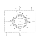
また、この実施形態のグロメット15は、例えば、次のようにして成形されるようになっている。すなわち、図3に示すように、グロメット15の脚部30の外周形状や、頭部20の外周形状の裏側は、主として、脚部30の軸方向に対して直交する方向で、かつ、互いに離れる方向にスライドする、第1型枠81及び第2型枠82によって成形される。また、図5に示すように、グロメット15の頭部20の外周形状の表側は、脚部30の軸方向に沿ってスライドする、第3型枠83によって成形される。
更に図5に示すように、第3型枠83の内側には、脚部30の軸方向に沿ってスライドする、ピン状の第4型枠84が配置されている。図9(A)に示すように、この第4型枠84は、脚部30の内周形状に対応した形状をなしており、拡径した拡径部85aを設けた、先端部85を有している。また、図9(A)~(D)に示すように、この第4型枠84が、グロメット成形後に、脚部30の軸方向に沿ってスライドして、無理抜きされることによって、グロメット15の頭部20や脚部30の内周形状が成形されるようになっている。
そして、グロメット15を成形する際には、上記の型枠81,82,83を閉じた後、型枠内に画成されたキャビティに、射出成形等によって、溶融した樹脂を充填することにより、グロメット15が成形される。その後、第1型枠81,第2型枠82を互いに離れる方向となるように移動させて抜型する。
更にその後、第3型枠83でグロメット15の頭部20の移動を規制しつつ、ピン状の第4型枠84を、脚部30の内側から無理抜き状態で引き抜いていく。このとき、図9(A)に示すように、第4型枠84の先端部85の拡径部85aが、一対の係合突部40,40の先端側斜面42,42に引っ掛かって、脚部30を押し広げる。更に第4型枠84が引き抜かれると、図9(B)に示すように、その先端部85の拡径部85aが、一対の係合突部40,40の頂部41,41に当接して、一対の係合突部40,40を更に押し広げる。この状態が脚部30が最も変形した状態となっている。
更に第4型枠84が引き抜かれると、図9(C)に示すように、先端部85の拡径部85aが、一対の係合突部40,40の頂部41,41を超えるので、変形した脚部30が徐々に弾性復帰し始める。更に第4型枠84が引き抜かれると、図9(D)に示すように、先端部85の拡径部85aが、一対の係合突部40,40に引っ掛からなくなり、無理抜き状態が解除されて、脚部30が弾性復帰して元の形状に戻るようになっている。
上記のように、第4型枠84を、脚部30の内側から引き抜いていくと、第4型枠84の先端部85が、一対の係合突部40,40に引っ掛かって、無理抜き状態となるが、このとき、脚部30の、一対の係合突部40,40を設けた箇所が、外側に広がるように変形し、一方、脚部30の、一対の係合突部40,40を設けていない箇所は、内側に凹むように変形する傾向となっていた。
しかしながら、この留め具10においては、図3に示すように、グロメット15の脚部30の内面には、脚部30の軸方向から見て、脚部30の軸心Cを挟んで、一対の係合突部40,40に重ならない位置に、軸方向に伸びる一対の第1リブ50,50が設けられているので、上述したように、脚部30の内側から第4型枠84が無理抜きされる際に、脚部30の一対の係合突部40,40を設けていない箇所が変形しても、第4型枠84の抜型後、すなわち、図9(D)に示す状態となったときに、一対の第1リブ50,50によって、変形した箇所が元の形状に戻りやすくなり、脚部30の変形を抑制することができる。その結果、一対の係止部35,35の、取付孔3の裏側周縁に対する、係りしろの減少を抑えることができ、取付孔3に対して留め具10を、所定の抜去力(取付孔から抜けないようにするための保持力)が得られるように、しっかりと取付けることができる。
また、この実施形態においては、図3に示すように、脚部30の軸方向基端側の内面には、脚部30の軸方向から見て、一対の係合突部40に重なる位置に、一対の第2リブ55,55が設けられている。そのため、ピン状の第4型枠84が、脚部30の内側から無理抜きされる際に、脚部30の一対の係合突部40,40を設けた箇所が変形しても、第4型枠84の抜型後に、一対の第2リブ55,55によって、変形した箇所を元の形状に戻しやすくすることができ、一対の係止部35,35の、取付孔3の裏側周縁に対する係りしろを、十分に確保することができる。また、係合突部40とピン部材60との係りしろ(ここでは、係合突部40の先端側斜面42に対する、ピン部材60の係止段部67aの係りしろ)を十分に確保することができ、グロメット15の脚部30に対するピン部材60の抜け止め保持力を高めることができる。
更にこの実施形態においては、図3に示すように、一対の係止部35,35と、一対の係合突部40,40とは、脚部30の軸方向から見て、重ならない位置に設けられている。そのため、ピン状の第4型枠84が、脚部30の内側から無理抜きされる際に、脚部30を変形させやすくして、第4型枠84を抜型しやすくすることができるので、脚部30の変形箇所が、一対の第1リブ50,50や、一対の第2リブ55,55によって、元の形状に戻りやすくすることができ、その結果、脚部30の変形をより効果的に抑制することができ、一対の係止部35,35の、取付孔3の裏側周縁に対する係りしろを、より十分に確保することができる。
また、この実施形態においては、図3に示すように、一対の第1リブ50,50は、少なくとも一対の係止部35,35が設けられた位置に対応する、脚部30の内面に設けられているので、一対の係止部35,35の強度を高めることができ、一対の係止部35,35の、取付孔3の裏側周縁に対する係止力を高めて、抜去力を向上させることができる。
更に、この実施形態においては、図5や図6に示すように、脚部30の軸方向先端側の内面には、一対の係合突部40に連続して、脚部30の軸方向先端側に向けて次第に内径方向に突出する、突出部44が設けられている。このような突出部44を設けたことによって、ピン状の第4型枠84の先端部85の外周が、突出部44の分だけ縮径するため、第4型枠84が脚部30の内側から無理抜きされる際に、その先端部85が、一対の係合突部40,40に引っ掛かりにくくなって、第4型枠84を脚部30の内側からスムーズに抜型することができる。また、突出部44によって、脚部30の内面の軸方向先端側の強度を高めることができ、第4型枠84が脚部30の内側から無理抜きされる際に、脚部30の過度の変形を抑制することができる。
また、この実施形態においては、図1や図2に示すように、記脚部30は、その軸方向の途中の外面に設けられた段部33を介して、軸方向先端側が軸方向基端側よりも縮径した形状をなしているので、取付孔3に対して、脚部30を軸方向先端側から挿入しやすくすることができる。これに加えて、一対の係止部35,35は、脚部30の外面において、段部33を脚部30の軸方向に跨ぐようにして設けられているので、脚部30を縮径しづらくすることができ、一対の係止部35,35の、取付孔3の裏側周縁への係止力をより高めて、その抜去力を更に向上させることができる。
なお、本発明は、上述した実施形態に限定されるものではなく、本発明の要旨の範囲内で、各種の変形実施形態が可能であり、そのような実施形態も本発明の範囲に含まれる。
3 取付孔
10 留め具
15 グロメット
20 頭部
21 開口部
30 脚部
35,35 係止部
40,40 係合突部
44 突出部
50,50 第1リブ
55,55 第2リブ
60 ピン部材
70 クッション部材
10 留め具
15 グロメット
20 頭部
21 開口部
30 脚部
35,35 係止部
40,40 係合突部
44 突出部
50,50 第1リブ
55,55 第2リブ
60 ピン部材
70 クッション部材
Claims (6)
- 取付孔に挿入されて取付けられる留め具であって、
前記取付孔の表側に配置される頭部、及び、該頭部から延出した有底筒状をなした脚部を有するグロメットと、
前記グロメットの前記脚部内に挿入されるピン部材とを有し、
前記脚部は、その外面に設けられ、前記取付孔の裏側周縁に係止する少なくとも一対の係止部と、内面に設けられ、前記ピン部材に係合する一対の係合突部とを有しており、
前記脚部の内面には、前記脚部の軸方向から見て、前記脚部の軸心を挟んで、前記一対の係合突部に重ならない位置に、軸方向に伸びる一対の第1リブが設けられていることを特徴とする留め具。 - 前記脚部の軸方向基端側の内面には、前記脚部の軸方向から見て、前記一対の係合突部に重なる位置に、一対の第2リブが設けられている請求項1記載の留め具。
- 少なくとも前記一対の係止部と、前記一対の係合突部とは、前記脚部の軸方向から見て、重ならない位置に設けられている請求項1又は2記載の留め具。
- 前記一対の第1リブは、少なくとも前記一対の係止部が設けられた位置に対応する、前記脚部の内面に設けられている請求項1~3のいずれか1つに記載の留め具。
- 前記脚部の軸方向先端側の内面には、前記一対の係合突部に連続して、前記脚部の軸方向先端に向けて次第に内径方向に突出する突出部が設けられている請求項1~4のいずれか1つに記載の留め具。
- 前記脚部は、その軸方向の途中の外面に設けられた段部を介して、軸方向先端側が軸方向基端側よりも縮径した形状をなしており、
少なくとも前記一対の係止部は、前記脚部の外面において、前記段部を前記脚部の軸方向に跨ぐようにして設けられている請求項1~5のいずれか1つに記載の留め具。
Priority Applications (1)
| Application Number | Priority Date | Filing Date | Title |
|---|---|---|---|
| JP2019525482A JP6832425B2 (ja) | 2017-06-19 | 2018-06-13 | 留め具 |
Applications Claiming Priority (2)
| Application Number | Priority Date | Filing Date | Title |
|---|---|---|---|
| JP2017-119268 | 2017-06-19 | ||
| JP2017119268 | 2017-06-19 |
Publications (1)
| Publication Number | Publication Date |
|---|---|
| WO2018235692A1 true WO2018235692A1 (ja) | 2018-12-27 |
Family
ID=64737049
Family Applications (1)
| Application Number | Title | Priority Date | Filing Date |
|---|---|---|---|
| PCT/JP2018/022561 Ceased WO2018235692A1 (ja) | 2017-06-19 | 2018-06-13 | 留め具 |
Country Status (2)
| Country | Link |
|---|---|
| JP (1) | JP6832425B2 (ja) |
| WO (1) | WO2018235692A1 (ja) |
Citations (5)
| Publication number | Priority date | Publication date | Assignee | Title |
|---|---|---|---|---|
| JPS62194014A (ja) * | 1986-02-17 | 1987-08-26 | アイ.テイ.ダブリユ.ドウ フランス | パネル用固定装置 |
| JPH0651518U (ja) * | 1992-12-15 | 1994-07-15 | 株式会社ニフコ | 雌 具 |
| JPH0814231A (ja) * | 1994-06-28 | 1996-01-16 | Piolax Inc | 止め具 |
| JP2003072599A (ja) * | 2001-09-05 | 2003-03-12 | Piolax Inc | 防水型クリップ |
| JP2005047325A (ja) * | 2003-07-31 | 2005-02-24 | Nippon Pop Rivets & Fasteners Ltd | カーテンシールドエアバッグ用クリップ |
-
2018
- 2018-06-13 JP JP2019525482A patent/JP6832425B2/ja active Active
- 2018-06-13 WO PCT/JP2018/022561 patent/WO2018235692A1/ja not_active Ceased
Patent Citations (5)
| Publication number | Priority date | Publication date | Assignee | Title |
|---|---|---|---|---|
| JPS62194014A (ja) * | 1986-02-17 | 1987-08-26 | アイ.テイ.ダブリユ.ドウ フランス | パネル用固定装置 |
| JPH0651518U (ja) * | 1992-12-15 | 1994-07-15 | 株式会社ニフコ | 雌 具 |
| JPH0814231A (ja) * | 1994-06-28 | 1996-01-16 | Piolax Inc | 止め具 |
| JP2003072599A (ja) * | 2001-09-05 | 2003-03-12 | Piolax Inc | 防水型クリップ |
| JP2005047325A (ja) * | 2003-07-31 | 2005-02-24 | Nippon Pop Rivets & Fasteners Ltd | カーテンシールドエアバッグ用クリップ |
Also Published As
| Publication number | Publication date |
|---|---|
| JP6832425B2 (ja) | 2021-02-24 |
| JPWO2018235692A1 (ja) | 2020-03-26 |
Similar Documents
| Publication | Publication Date | Title |
|---|---|---|
| US8393058B2 (en) | Clip | |
| JP2000041320A (ja) | グロメット | |
| JP2018179051A (ja) | クリップ | |
| US20130145585A1 (en) | Clip | |
| US4821381A (en) | Fastener made of synthetic resin | |
| JP2014070668A (ja) | クリップ | |
| JP2014019333A (ja) | アームレストの芯材 | |
| JP4006499B2 (ja) | 一体成形クリップの成形方法 | |
| JP2019052673A (ja) | クリップ | |
| JP6832425B2 (ja) | 留め具 | |
| JP2016191462A (ja) | ホールプラグ | |
| JPWO2019035273A1 (ja) | クリップ | |
| JP2000192918A (ja) | 車両用内装部品のクリップ取付座 | |
| JPS6234016Y2 (ja) | ||
| JP2020192913A (ja) | 車両用加飾部材固定構造 | |
| JP5934592B2 (ja) | クリップ及びその製造方法 | |
| JP7211882B2 (ja) | 取付構造 | |
| JP4036517B2 (ja) | 自動車用内装部品のクリップ取付座 | |
| JP2021071149A (ja) | 留め具 | |
| JP2013079726A (ja) | クリップ | |
| JP2004144158A (ja) | パネル孔への取付け具 | |
| JP7504814B2 (ja) | クリップ | |
| JP2023155598A (ja) | 留め具 | |
| JPH0247288Y2 (ja) | ||
| JP5881281B2 (ja) | 発泡成形体の取付部材、発泡成形部材、発泡成形部材の製造方法並びに発泡成形部材の取付構造 |
Legal Events
| Date | Code | Title | Description |
|---|---|---|---|
| 121 | Ep: the epo has been informed by wipo that ep was designated in this application |
Ref document number: 18821141 Country of ref document: EP Kind code of ref document: A1 |
|
| DPE1 | Request for preliminary examination filed after expiration of 19th month from priority date (pct application filed from 20040101) | ||
| ENP | Entry into the national phase |
Ref document number: 2019525482 Country of ref document: JP Kind code of ref document: A |
|
| NENP | Non-entry into the national phase |
Ref country code: DE |
|
| 122 | Ep: pct application non-entry in european phase |
Ref document number: 18821141 Country of ref document: EP Kind code of ref document: A1 |