WO2018235528A1 - Unité et dispositif d'application - Google Patents
Unité et dispositif d'application Download PDFInfo
- Publication number
- WO2018235528A1 WO2018235528A1 PCT/JP2018/020340 JP2018020340W WO2018235528A1 WO 2018235528 A1 WO2018235528 A1 WO 2018235528A1 JP 2018020340 W JP2018020340 W JP 2018020340W WO 2018235528 A1 WO2018235528 A1 WO 2018235528A1
- Authority
- WO
- WIPO (PCT)
- Prior art keywords
- container
- hole
- negative pressure
- liquid material
- application
- Prior art date
Links
Images


Classifications
-
- B—PERFORMING OPERATIONS; TRANSPORTING
- B05—SPRAYING OR ATOMISING IN GENERAL; APPLYING FLUENT MATERIALS TO SURFACES, IN GENERAL
- B05C—APPARATUS FOR APPLYING FLUENT MATERIALS TO SURFACES, IN GENERAL
- B05C1/00—Apparatus in which liquid or other fluent material is applied to the surface of the work by contact with a member carrying the liquid or other fluent material, e.g. a porous member loaded with a liquid to be applied as a coating
- B05C1/02—Apparatus in which liquid or other fluent material is applied to the surface of the work by contact with a member carrying the liquid or other fluent material, e.g. a porous member loaded with a liquid to be applied as a coating for applying liquid or other fluent material to separate articles
-
- B—PERFORMING OPERATIONS; TRANSPORTING
- B05—SPRAYING OR ATOMISING IN GENERAL; APPLYING FLUENT MATERIALS TO SURFACES, IN GENERAL
- B05C—APPARATUS FOR APPLYING FLUENT MATERIALS TO SURFACES, IN GENERAL
- B05C11/00—Component parts, details or accessories not specifically provided for in groups B05C1/00 - B05C9/00
- B05C11/10—Storage, supply or control of liquid or other fluent material; Recovery of excess liquid or other fluent material
Definitions
- the present invention relates to a coating unit and a coating apparatus for applying a liquid material to an object using a coating needle.
- Printed electronics technology for forming fine circuits such as RFID (Radio Frequency Identifier) tags by a printing (application) method has been rapidly developed.
- a printing method, an inkjet method, etc. are generally used as a method of forming a fine pattern
- a method using a coating needle is also an option in that fine coating can be performed using a material with a wide range of viscosity. one of.
- Patent Document 1 As a method of performing fine coating using a coating needle, there is a method of using a coating unit as described in JP-A-2007-268353 (Patent Document 1).
- the liquid material is contained in the container.
- a through hole through which the application needle can be inserted is formed below the internal space containing the liquid material.
- the application unit described above applies the liquid material to the target object in the first state in which the tip of the application needle is immersed in the liquid material in the container, and the tip of the application needle protrudes downward from the through hole formed in the container
- the possible second state can be taken.
- FIG. 7 is a view showing a state change of the coating needle in the conventional coating unit.
- (a) shows a first state
- (b) shows a second state.
- (C) shows a first state after repeatedly switching between the first state and the second state when the viscosity of the liquid material L is low.
- (D) shows a first state after repeatedly switching between the first state and the second state when the viscosity of the liquid material L is high.
- the application needle 117 protrudes from the through hole 182 of the container 118, whereby the liquid material L adhering to the periphery of the application needle 117 comes out of the through hole 182, to the object 140. It is applied.
- the viscosity of the liquid material L is low, as shown in FIG. 7C, as the tip of the application needle 117 moves into the container 118, the liquid material L deposited around the application needle 117 is also the container 118.
- the liquid material L is, for example, a high-viscosity conductive material in which metal powder is dispersed, switching between the first state and the second state is repeated a plurality of times, as shown in FIG.
- a reservoir 50 of the liquid material L is formed on an area around the through hole 182 in the outer peripheral surface of the container 118 and below the through hole 182.
- the reservoir portion 50 of the liquid material L is formed by the liquid material L remaining protruded from the through hole 182 regardless of the movement of the tip of the application needle 117 into the container 118.
- the above-described reservoir portion 50 is formed because the specific gravity of the liquid material L is large and the flowability is low.
- the present invention has been made to solve the above-mentioned problems, and an object thereof is to provide a coating unit and a coating apparatus capable of stably coating a liquid material for a long time.
- the application unit of the present disclosure has a container in which a first through hole is formed in the bottom and into which the liquid material is injected, an application needle for applying the liquid material to an object by projecting from the first through hole, and a container And a negative pressure source for making negative pressure.
- the negative pressure source makes the pressure in the container negative by suctioning the gas in the container.
- the application unit controls the suction force of the negative pressure source so that the pressure in the container becomes constant based on the pressure sensor for detecting the pressure in the container and the pressure detected by the pressure sensor. And a unit.
- the negative pressure source makes the pressure in the container negative by suctioning the gas in the container.
- the application unit measures the amount of projection of the liquid material from the through hole on the basis of the camera for imaging the first through hole and the image obtained by the imaging of the camera, so that the amount of projection becomes constant.
- a controller for controlling the suction force of the pressure source.
- the container is provided with a suction hole for taking in the outside air into the container when the container is negatively pressurized by the negative pressure source.
- the container is provided with a second through hole for sucking the gas in the container by the negative pressure source.
- the diameter of the suction hole is 1/3 or less of the diameter of the second through hole.
- the application unit further comprises a support for supporting the container.
- the container comprises a container body and a crucible formed on the side of the container body.
- the container is formed with a second through hole for sucking the gas in the container by the negative pressure source.
- the second through hole opens to the inner surface of the container body and the lower surface of the crucible.
- the support portion is formed with a hole through which the container body can be inserted, a groove opened on the upper surface, and a third through hole communicating with the groove.
- the support portion supports the container by being in contact with the lower surface of the crucible in a state where the container body is inserted into the hole.
- the groove is covered by the crucible when the container is supported by the support, and in communication with the second through hole.
- the application device of the present disclosure applies a liquid material to an object using the application unit described above.
- the liquid material can be stably applied for a long time.
- FIG. 14 is a partial cross-sectional view showing a coating unit according to a modification 4; It is a fragmentary sectional view which shows the application
- FIG. 10 is a bottom view of the container shown in FIG. 9; It is a top view of the support part shown by FIG.
- FIG. 1 is a view schematically showing the configuration of a coating apparatus provided with a coating unit according to the present embodiment.
- the coating device 200 patterns a conductive material on an RFID tag or the like, and corrects an open defect of a wiring pattern.
- the coating apparatus 200 includes a coating unit 100, an observation optical system 110, a CCD camera 111 connected to the observation optical system 110, a Z-axis table 120, an X-axis table 121, and Y It includes an axis table 122, a base 123, an operation panel 131, a monitor 132, and a control computer 133.
- the observation optical system 110 is provided to observe the application position of the object 140 (for example, the substrate).
- the CCD camera 111 converts the image observed by the observation optical system 110 into an electrical signal.
- the application unit 100 applies the liquid material to the object 140.
- the observation optical system 110, the CCD camera 111, and the coating unit 100 are mounted on the movable body of the Z-axis table 120.
- the observation optical system 110, the CCD camera 111, and the coating unit 100 are supported by the Z-axis table 120 so as to be movable in the Z-axis direction in FIG.
- the Z-axis table 120 is mounted on the movable body of the X-axis table 121.
- the Z-axis table 120 is supported by the X-axis table 121 so as to be movable in the X-axis direction in FIG.
- the object 140 is placed on the Y-axis table 122.
- the Y-axis table 122 is provided movably in the Y-axis direction in FIG.
- the object 140 is movably supported by the Y-axis table 122 in the Y-axis direction.
- the Y-axis table 122 is installed on the upper surface of the base 123.
- the Z-axis direction in FIG. 1 is a direction along the gravity direction.
- the control computer 133 controls the coating unit 100, the observation optical system 110, the Z-axis table 120, the X-axis table 121, and the Y-axis table 122.
- the operation panel 131 is used to input an instruction to the control computer 133.
- the monitor 132 displays the image data converted by the CCD camera 111 of the observation optical system 110 and the output data from the control computer 133.
- FIG. 2 is a front view of the application unit 100.
- FIG. 3 is a side view of the coating unit 100.
- FIG. 4 is a plan view of the container 18 provided in the application unit 100 and the peripheral configuration thereof.
- FIG. 5 is a partial cross-sectional view showing the container 18 provided in the application unit 100 and the peripheral configuration thereof.
- the application unit 100 includes a base 10, a servomotor 11, a cam 12, a bearing 13, a cam connection plate 14, a movable portion 15, an application needle holder 16, and an application supported by the application needle holder 16.
- a needle 17, a container 18, a suction tube 19, a vacuum pump 20, a pressure sensor 21, a pressure control valve 22, and a control device 23 are mainly provided.
- the servomotor 11 is installed on the base 10 so that the rotation axis extends in the direction along the Z-axis direction shown in FIG.
- a cam 12 is connected to the rotation shaft of the servomotor 11.
- the cam 12 is rotatable around the rotation axis of the servomotor 11.
- the lower surface 12 b of the cam 12 is a plane perpendicular to the rotation axis of the servomotor 11.
- the upper surface 12 a of the cam 12 is inclined with respect to the lower surface of the cam 12. That is, the upper surface 12 a of the cam 12 is inclined with respect to a plane perpendicular to the rotation axis of the servomotor 11.
- the bearing 13 is disposed in contact with the upper surface 12 a of the cam 12.
- the bearing 13 is disposed in a specific direction (right side of the servomotor 11) when viewed from the cam 12 as shown in FIG.
- the bearing 13 is kept in contact with the upper surface 12 a of the cam 12 when the cam 12 is rotated by the rotation of the rotation shaft of the servomotor 11.
- the cam connection plate 14 is connected to the bearing 13.
- the other end of the cam connection plate 14 opposite to the one end connected to the bearing 13 is fixed to the movable portion 15.
- the application needle holder fixing portion 24 and the application needle holder storage portion 25 are connected to the movable portion 15.
- the application needle holder 16 supports the application needle 17 and is detachably stored in the application needle holder storage unit 25.
- the application needle 17 is attachable to and detachable from the application needle holder storage 25 via the application needle holder 16.
- the application needle 17 is disposed so as to protrude from the application needle holder 16 on the lower surface of the application needle holder 16 (the lower side opposite to the side where the servo motor 11 is located).
- a container 18 is disposed under the application needle holder 16. The application needle 17 is supported in a state of being inserted into the container 18.
- the fixed pin 26 is installed on the movable portion 15. Furthermore, another fixing pin 27 is installed on the base 10 holding the servomotor 11.
- a spring 28 is provided to connect the fixing pins 26 and 27.
- the movable portion 15 is in a state of being subjected to a tensile force directed to the container 18 side by the spring 28.
- the tensile force of the spring 28 acts on the bearing 13 via the movable portion 15 and the cam connection plate 14.
- the tensile force of the spring 28 keeps the bearing 13 pressed against the upper surface 12 a of the cam 12.
- the movable portion 15, the application needle holder fixing portion 24 and the application needle holder storage portion 25 move along a linear guide 29 installed on the base 10.
- the linear guide 29 is arranged to extend in the Z-axis direction. Therefore, the movable portion 15, the application needle holder fixing portion 24, and the application needle holder storage portion 25 are movable along the Z-axis direction.
- the upper surface 12 a of the cam 12 is inclined with respect to a plane perpendicular to the rotation axis of the servomotor 11. Therefore, when the cam 12 is rotated by the rotation of the rotation shaft of the servomotor 11, the bearing 13 pressed by the upper surface 12 a of the cam 12 moves up and down along the rotation shaft of the servomotor 11.
- the needle 17 also moves up and down along the rotation axis of the servomotor 11. That is, the rotational movement of the servomotor 11 is converted to the vertical linear movement of the application needle 17 through the cam 12.
- the highest position that the application needle 17 can take is called a "first position”
- the lowest position is called a "second position”.
- the container 18 is supported by the base 10.
- the container 18 includes, for example, a magnet (not shown), and is detachably supported on the base 10 by the magnetic force generated between the magnet and the magnet of the base 10.
- a space for injecting the liquid material L is formed inside the container 18.
- the liquid material L is, for example, a high viscosity conductive material in which metal powder is dispersed.
- the container 18 includes a container body 18a whose upper end is largely opened and a lid 18b for closing the opening of the upper end of the container body 18a.
- the lid 18 b is formed with a through hole 81 through which the application needle 17 can be inserted.
- the tip of the application needle 17 penetrates the through hole 81 and is immersed in the liquid material L stored in the container 18.
- the bottom of the container body 18a has a substantially inverted conical shape.
- a through hole 82 communicating the inside and the outside of the container 18 is formed at the lower end of the bottom of the container body 18a.
- the through hole 82 can penetrate the coating needle 17 and can project the tip of the coating needle 17 downward, and the size is set so that the liquid material L stored in the container 18 does not drip off .
- the hole axis of the through hole 82 coincides with the hole axis of the through hole 81.
- a through-hole between the tip position of the application needle 17 when the application needle 17 is positioned at the first position and the tip position of the application needle 17 when the application needle 17 is positioned at the second position The container body 18a is disposed such that 82 is located.
- the coating unit 100 is in the first state in which the tip of the coating needle 17 is positioned in the space inside the container 18, and the tip of the coating needle 17 is through the through hole 82. It can take the second state which has protruded.
- a through hole 83 communicating the inside and the outside of the container 18 is also formed on the side wall of the container body 18 a.
- the through holes 83 are used to suction the gas (air) inside the container 18. Therefore, the liquid material L has a liquid level lower than that of the through hole 83 and a space inside the container 18 so that the liquid level is higher than the tip position of the application needle 17 positioned at the first position. Be injected. This can prevent the liquid material L from being sucked from the through holes 83 to the outside. Furthermore, when the application needle 17 is located at the first position, the tip of the application needle 17 can be immersed in the liquid material L.
- the lid 18b is formed with a suction hole 84 for communicating the inside and the outside of the container 18 with each other.
- the suction holes 84 are used to suck external air into the interior of the container 18.
- One end of the suction tube 19 is connected to the container body 18 a so that the internal space is continuous with the through hole 83.
- a vacuum pump 20 is connected to the other end of the suction tube 19. By operating the vacuum pump 20, the gas (air) in the container 18 is sucked through the suction tube 19, and the inside of the container 18 is under negative pressure.
- the pressure sensor 21 is attached to the suction tube 19 and measures the pressure (atmospheric pressure) in the suction tube 19.
- the pressure control valve 22 is attached to the suction tube 19 to adjust the flow rate of gas in the suction tube 19.
- the suction force by the vacuum pump 20 is controlled by the open / close state of the pressure control valve 22.
- the controller 23 controls the pressure in the container 18.
- Control device 23 includes a control unit 231 and a storage unit 232.
- the target value of the pressure in the container 18 is stored in advance.
- the control unit 231 compares the value measured by the pressure sensor 21 with the target value stored in the storage unit 232, and controls the open / close state of the pressure control valve 22 according to the comparison result to target the pressure in the container 18 Stabilize around the value. Specifically, when the difference between the measurement value of the pressure sensor 21 and the target value is within the predetermined range, the control unit 231 does not change the open / close state of the pressure control valve 22.
- the control unit 231 controls the open / close state of the pressure control valve 22 in the opening direction when the difference between the measured value of the pressure sensor 21 and the target value is outside the predetermined range and the measured value is larger than the target value. Do. As a result, the suction force of the vacuum pump 20 is increased, and the pressure in the container 18 is reduced so as to approach the target value.
- the control unit 231 controls the open / close state of the pressure control valve 22 in the closing direction side when the difference between the measured value of the pressure sensor 21 and the target value is outside the predetermined range and the measured value is smaller than the target value. Do. As a result, the suction force of the vacuum pump 20 decreases, and the pressure in the container 18 increases so as to approach the target value.
- the target value stored in the storage unit 232 is appropriately set according to the volume of the container 18, the viscosity of the liquid material L, the remaining amount of the liquid material L, and the like.
- Control unit 231 is formed of, for example, a central processing unit (CPU), a read only memory (ROM), and a random access memory (RAM). These parts are connected to one another via an internal bus.
- the CPU loads a program stored in the ROM into a RAM or the like and executes the program.
- the program stored in the ROM is a program in which the processing method of the control unit 231 is written.
- Storage unit 232 is, for example, a non-volatile memory.
- the through hole 82 is formed in the bottom, and the container 18 into which the liquid material L is injected and the liquid material L as an object by projecting from the through hole 82.
- a vacuum pump (negative pressure source) 20 for making the inside of the container 18 have a negative pressure.
- the inside of the container 18 is maintained at a negative pressure by the negative pressure source. Therefore, the liquid material L that has been applied to the outside of the container 18 due to the application needle 17 protruding from the through hole 82 but has not been applied to the object 140 is the container 18 when the application needle 17 returns into the container 18. Sucked inside. This can suppress the formation of the reservoir portion 50 of the liquid material L as shown in FIG. 7D outside the through hole 82 of the container 18. As a result, when the application needle 17 protrudes from the through hole 82, the amount of the liquid material L adhering to the tip of the application needle 17 is stabilized, and the liquid is a high viscosity material in which metal powder is dispersed. The material can be stably applied for a long time.
- the vacuum pump 20 is a negative pressure source that makes the inside of the container 18 negative by sucking the gas in the container 18.
- the coating unit 100 is a vacuum pump so that the pressure in the container 18 becomes constant based on the pressure sensor (pressure detector) 21 for detecting the pressure in the container 18 and the pressure detected by the pressure sensor 21. And a control unit 231 for controlling a suction force of 20. Thereby, the pressure in the container 18 is kept constant, and the liquid material can be applied more stably.
- the container 18 is formed with a suction hole 84 for taking in the outside air into the container 18 when the inside of the container 18 is depressurized by the vacuum pump 20.
- the air in the container 18 is sucked by the vacuum pump 20
- the outside air is taken into the container 18 from the suction hole 84.
- the pressure in the container 18 can be prevented from being excessively reduced, and the pressure in the container 18 can be continuously kept substantially constant.
- the pressure in the container 18 decreases too much, the liquid material L is completely sucked into the container 18 from the through hole 82 and adheres to the tip of the application needle 17 when the application needle 17 protrudes from the through hole 82.
- the amount of liquid material L decreases.
- the pressure in the container 18 is prevented from being excessively reduced, and the amount of the liquid material L adhering to the tip of the application needle 17 when the application needle 17 protrudes from the through hole 82 is further stabilized. Can.
- FIG. 6 is a partial cross-sectional view showing the container of the coating unit according to the modification and the peripheral configuration thereof.
- the application unit according to the modification is different from the application unit 100 described above in that a camera 30 and a control device 23a are provided instead of the pressure sensor 21 and the control device 23.
- the camera 30 is constituted by, for example, a CCD (Charge-Coupled Device) image sensor, and images the through hole 82 of the container 18 and the periphery thereof.
- the camera 30 picks up an image each time a single coating process is performed by the coating needle 17.
- the control device 23 a controls the open / close state of the pressure control valve 22 based on the image data obtained by the imaging of the camera 30.
- the control device 23a includes a control unit 233 and a storage unit 234.
- the control unit 233 acquires image data obtained by imaging each time the camera 30 performs imaging.
- the control unit 233 performs image processing on the image data, and calculates the amount of protrusion of the liquid material L protruding from the through hole 82 from the through hole 82.
- the control unit 233 performs edge extraction processing on image data, specifies the surface of the liquid material L, and calculates the distance from the through hole 82 to the surface as the amount of protrusion.
- the control unit 233 associates each image data with identification information for identifying the imaging order of the image data, and the amount of projection calculated from the image data, and stores the association in the storage unit 234.
- the identification information is, for example, a number indicating an imaging order or an imaging date and time.
- the control unit 233 determines whether the amount of protrusion calculated from the latest image data is within a predetermined range. If the amount of protrusion calculated from the latest image data is out of the predetermined range, the control unit 233 compares the amount of protrusion with the amount of protrusion in the past.
- the past protrusion amount may be a protrusion amount calculated from the previous image data, or may be an average value of the protrusion amounts calculated from a plurality of past image data.
- the control unit 233 causes the pressure control valve 22 to open and close the opening direction Control. As a result, the pressure in the container 18 is further reduced, and the amount of protrusion of the liquid material L from the through hole 82 is reduced.
- the controller 233 closes the open / close state of the pressure control valve 22 Control. Thereby, it can suppress that the pressure in the container 18 becomes small too much.
- the control unit 233 When the amount of protrusion calculated from the latest image data is within the predetermined range, the control unit 233 does not change the open / close state of the pressure control valve 22. Although the protrusion amount calculated from the latest image data exceeds the upper limit value of the predetermined range, the control unit 233 does not change the open / close state of the pressure control valve 22 even when the latest protrusion amount is equal to or less than the past protrusion amount. Furthermore, although the protrusion amount calculated from the latest image data is less than the lower limit value of the predetermined range, the control unit 233 changes the open / close state of the pressure control valve 22 even when the latest protrusion amount is greater than the past protrusion amount. do not do.
- the amount of projection of the liquid material L from the through hole 82 is stabilized, the amount of the liquid material L adhering to the tip of the application needle 17 when the application needle 17 protrudes from the through hole 82 is more stable. As a result, the liquid material L can be applied more stably for a long time.
- control unit 233 uses the result of comparison between the amount of projection calculated from the latest image data and a predetermined range, and the result of comparison between the amount of projection calculated from the latest image data and the amount of projection in the past. Based on this, the open / close state of the pressure control valve 22 was controlled. However, based on either the comparison result between the projection amount calculated from the latest image data and the predetermined range or the comparison result between the projection amount calculated from the latest image data and the projection amount in the past, the control unit 233 The open / close state of the pressure control valve 22 may be controlled.
- Control unit 233 is configured of, for example, a CPU, a ROM, and a RAM, as control unit 231 does. Similar to the storage unit 232, the storage unit 234 is, for example, a non-volatile memory.
- the through hole 83 for providing a negative pressure in the container 18 is formed on the side wall of the container body 18a, but the through hole 83 may be formed on the lid 18b.
- the suction hole 84 is formed in the lid 18b, the suction hole 84 may be formed in the side wall of the container body 18a.
- the vacuum pump 20 is used as a negative pressure source for making the inside of the container 18 negative pressure.
- the negative pressure source is not limited to the vacuum pump 20, and may be another device.
- a vacuum ejector utilizing existing compressed air equipment may be used. Thereby, a compact coating unit can be manufactured inexpensively.
- the maximum negative pressure obtained by the vacuum ejector is generally about -80 kPa, which is smaller in absolute value than the vacuum pump. Therefore, when the diameter of the suction hole 84 is larger than the diameter of the through hole 83, the flow rate of the outside air from the suction hole 84 into the container 18 becomes approximately the same as the flow rate of the gas drawn from the through hole 83. The inside can not be put under negative pressure sufficiently. Therefore, when using a vacuum ejector having a maximum negative pressure of about -80 kPa as the negative pressure source, the diameter of the suction hole 84 is 1/1 of the diameter of the through hole 83 for sucking the gas in the container 18 by the negative pressure source. It is preferable that it is 3 or less.
- the diameter of the through hole 83 means the smallest diameter of the through holes 83. This is because the flow rate of the gas in the through hole 83 when the vacuum ejector is operated is determined at the narrowest portion of the through hole 83.
- FIG. 8 shows the change in the amount of protrusion when the absolute value of the set negative pressure is increased from the state in which the reservoir portion of the liquid material L protrudes by 1 mm from the through hole 82 of the container 18.
- a negative pressure source a vacuum ejector with a maximum negative pressure of -80 kPa is used.
- the container 18 is detachably supported on the base 10 by magnetic force.
- the method of supporting the container by the base 10 is not limited to this.
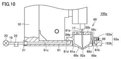
- FIG. 9 is a partial cross-sectional view showing a coating unit 100a according to a fourth modification.
- FIG. 9 shows the coating unit 100a when the coating needle 17 is positioned at the highest position.
- FIG. 10 is a partial cross-sectional view showing a coating unit 100a according to the fourth modification when the coating needle 17 is lowered.
- 11 is a bottom view of the container 68 shown in FIG.
- FIG. 12 is a plan view of the support portion 61 shown in FIG.
- the application unit 100a includes a container 68 instead of the container 18 as compared to the application unit 100 described above, and a support 61 for supporting the container 68. It differs only in.
- the configuration other than these points is the same as that of the coating unit 100, and thus the detailed description is omitted.
- the container 68 includes a container body 68a, a lid 68b and a weir 68c.
- the container main body 68a has, for example, a bottomed cylindrical shape whose upper end is open.
- the bottom of the container body 68a has a substantially inverted conical shape.
- a through hole 82a communicating the inside and the outside of the container 68 is formed.
- the through hole 82a can penetrate the coating needle 17 so that the tip of the coating needle 17 can be protruded downward, and the size of the liquid material L stored in the container 68 is set so as not to drip off .
- the lid 68 b is a member for closing the opening at the upper end of the container body 68 a. Similar to the lid 18b, the lid 68b has a through hole 81a through which the application needle 17 can be inserted, and a suction hole 84a for sucking outside air into the container 68 when the vacuum pump 20 is operated. It is formed.
- the weir 68c is formed along the horizontal direction on the side surface of the container body 68a.
- the container 68 is formed with a through hole 83 a for sucking the gas (air) in the container 68 by the vacuum pump 20.
- the through hole 83a extends vertically downward from the middle of the upper through hole 183a passing through in the horizontal direction from the inner surface 68d of the container body 68a to the outer peripheral surface of the weir 68c, and opens in the lower surface 68e of the weir 68c. It is comprised from the lower side through-hole 183b.
- the opening of the outer peripheral surface of the weir 68 c in the upper through hole 183 a is closed by a screw 69. Therefore, the through hole 83a constitutes an L-shaped passage that opens to the inner surface 68d of the container body 68a and the lower surface 68e of the weir 68c.
- the support 61 is attached to the base 10.
- the support portion 61 may be integrally formed with the base 10.
- the support portion 61 has a plate shape and is disposed along the horizontal direction.
- the supporting portion 61 is formed with a hole 61a through which a portion of the container body 68a below the ridge 68c can be inserted.
- a groove 61b opened on the upper surface 61d is annularly formed.
- a through hole 61c which is connected to the groove 61b and extends in the horizontal direction is formed.
- the suction tube 19 is connected to the support portion 61 so as to communicate with the through hole 61 c.
- a vacuum pump 20, a pressure sensor 21, and a pressure control valve 22 are attached to the suction tube 19.
- the support portion 61 supports the container 68 by being in contact with the lower surface 68 e of the collar 68 c in a state where the lower portion of the container main body 68 a is inserted into the hole 61 a.
- the groove 61 b is covered by the weir 68 c and communicates with the lower through hole 183 b of the through hole 83 a formed in the container 68.
- the upper through holes 183a, the lower through holes 183b, the grooves 61b, and the through holes 61c form a flow path of gas drawn from the inside of the container 68.
- the container 68 can be easily desorbed, and by inserting the container body 68 a into the hole 61 a of the support portion 61, the flow path of the gas sucked from the inside of the container 68 is easy. Is formed.
- the container 68 When the container 68 is supported by the support portion 61, it is preferable to provide a gap between the outer peripheral surface of the container body 68a and the inner peripheral surface of the hole 61a of the support portion 61. As a result, the container body 68 a can be easily inserted into the hole 61 a of the support portion 61. Furthermore, even if the attachment position of the application needle 17 is displaced, the container 68 can be moved in the horizontal direction within the range of the gap according to the positional deviation of the application needle 17. As a result, the application needle 17 and the through holes 81a and 82a can be positioned at appropriate relative positions, and the application amount of the liquid material L from the container 68 can be stabilized.
- the width of the groove 61b is larger than the diameter of the lower through hole 183b so that the lower through hole 183b formed in the weir 68c communicates with the groove 61b. It is set large.
- a vacuum ejector having a maximum negative pressure of about ⁇ 80 kPa may be used instead of the vacuum pump 20, a vacuum ejector having a maximum negative pressure of about ⁇ 80 kPa may be used.
- the diameter of the suction hole 84a it is preferable to set the diameter of the suction hole 84a to 1/3 or less of the diameter of the through hole 83a.
- the diameter of the lower through hole 183b is set to the diameter of the upper through hole 183a in consideration of the positional deviation of the lower through hole 183b with respect to the upper through hole 183a. It may be set smaller than that.
- the diameter of the suction hole 84a be 1/3 or less of the diameter of the lower through hole 183b of the upper through hole 183a and the lower through hole 183b, whichever has the smaller diameter.
Landscapes
- Coating Apparatus (AREA)
Abstract
L'invention concerne une unité d'application pourvue : d'un récipient (18) qui présente un trou traversant (82) formé dans le fond et dans lequel un matériau liquide (L) est infusé ; d'une aiguille d'application (17) pour appliquer le matériau liquide (L) à une cible par le dépassement du trou traversant (82) ; et d'une pompe à vide (20) pour créer une pression négative à l'intérieur du récipient (18). Ainsi, il est possible d'appliquer de manière stable le matériau liquide sur une longue période de temps.
Applications Claiming Priority (4)
| Application Number | Priority Date | Filing Date | Title |
|---|---|---|---|
| JP2017-120597 | 2017-06-20 | ||
| JP2017120597 | 2017-06-20 | ||
| JP2017251032A JP6971146B2 (ja) | 2017-06-20 | 2017-12-27 | 塗布ユニットおよび塗布装置 |
| JP2017-251032 | 2017-12-27 |
Publications (1)
| Publication Number | Publication Date |
|---|---|
| WO2018235528A1 true WO2018235528A1 (fr) | 2018-12-27 |
Family
ID=64737153
Family Applications (1)
| Application Number | Title | Priority Date | Filing Date |
|---|---|---|---|
| PCT/JP2018/020340 WO2018235528A1 (fr) | 2017-06-20 | 2018-05-28 | Unité et dispositif d'application |
Country Status (1)
| Country | Link |
|---|---|
| WO (1) | WO2018235528A1 (fr) |
Cited By (1)
| Publication number | Priority date | Publication date | Assignee | Title |
|---|---|---|---|---|
| WO2021182613A1 (fr) * | 2020-03-13 | 2021-09-16 | Ntn株式会社 | Unité d'application de matériau liquide, dispositif d'application de matériau liquide et procédé d'application de matériau liquide |
Citations (6)
| Publication number | Priority date | Publication date | Assignee | Title |
|---|---|---|---|---|
| JP2006276188A (ja) * | 2005-03-28 | 2006-10-12 | Ntn Corp | パターン修正装置およびパターン修正方法 |
| JP2006310266A (ja) * | 2005-03-28 | 2006-11-09 | Ntn Corp | 塗布ユニットおよびパターン修正装置 |
| WO2010018675A1 (fr) * | 2008-08-13 | 2010-02-18 | 株式会社アプライド・マイクロシステム | Dispositif et procédé de déversement de liquide |
| JP2010264380A (ja) * | 2009-05-14 | 2010-11-25 | Panasonic Corp | 液体塗布方法および装置 |
| WO2016199696A1 (fr) * | 2015-06-09 | 2016-12-15 | Ntn株式会社 | Unité de revêtement et dispositif de revêtement la mettant en œuvre |
| WO2017090381A1 (fr) * | 2015-11-25 | 2017-06-01 | Ntn株式会社 | Unité de revêtement, dispositif de revêtement, procédé de production d'un objet à revêtir et procédé de production d'un substrat |
-
2018
- 2018-05-28 WO PCT/JP2018/020340 patent/WO2018235528A1/fr active Application Filing
Patent Citations (6)
| Publication number | Priority date | Publication date | Assignee | Title |
|---|---|---|---|---|
| JP2006276188A (ja) * | 2005-03-28 | 2006-10-12 | Ntn Corp | パターン修正装置およびパターン修正方法 |
| JP2006310266A (ja) * | 2005-03-28 | 2006-11-09 | Ntn Corp | 塗布ユニットおよびパターン修正装置 |
| WO2010018675A1 (fr) * | 2008-08-13 | 2010-02-18 | 株式会社アプライド・マイクロシステム | Dispositif et procédé de déversement de liquide |
| JP2010264380A (ja) * | 2009-05-14 | 2010-11-25 | Panasonic Corp | 液体塗布方法および装置 |
| WO2016199696A1 (fr) * | 2015-06-09 | 2016-12-15 | Ntn株式会社 | Unité de revêtement et dispositif de revêtement la mettant en œuvre |
| WO2017090381A1 (fr) * | 2015-11-25 | 2017-06-01 | Ntn株式会社 | Unité de revêtement, dispositif de revêtement, procédé de production d'un objet à revêtir et procédé de production d'un substrat |
Cited By (1)
| Publication number | Priority date | Publication date | Assignee | Title |
|---|---|---|---|---|
| WO2021182613A1 (fr) * | 2020-03-13 | 2021-09-16 | Ntn株式会社 | Unité d'application de matériau liquide, dispositif d'application de matériau liquide et procédé d'application de matériau liquide |
Similar Documents
| Publication | Publication Date | Title |
|---|---|---|
| WO2017090381A1 (fr) | Unité de revêtement, dispositif de revêtement, procédé de production d'un objet à revêtir et procédé de production d'un substrat | |
| KR101323213B1 (ko) | 유체 증착 장치 | |
| US9878391B2 (en) | Solder supply device | |
| JP6514047B2 (ja) | 塗布ユニットおよびそれを用いた塗布装置 | |
| JP6411735B2 (ja) | 塗布部材、塗布装置および塗布方法 | |
| JP6580874B2 (ja) | 液体塗布ユニットおよび液体塗布装置 | |
| WO2018235528A1 (fr) | Unité et dispositif d'application | |
| JP6971146B2 (ja) | 塗布ユニットおよび塗布装置 | |
| JP6560108B2 (ja) | 塗布ユニット、塗布装置、被塗布対象物の製造方法および基板の製造方法 | |
| JP5086708B2 (ja) | マスクブランクの製造方法及び塗布装置 | |
| JP6491296B2 (ja) | 塗布部材、塗布装置および塗布方法 | |
| CN107073513A (zh) | 涂布方法及涂布装置 | |
| US11897264B2 (en) | Liquid application unit and liquid application apparatus | |
| JP2018034124A (ja) | 液体塗布ユニットおよび液体塗布装置 | |
| JP6587945B2 (ja) | 塗布機構、塗布装置、被塗布対象物の製造方法、および基板の製造方法 | |
| JP6716654B2 (ja) | 塗布部材、塗布装置および塗布方法 | |
| JP2009206061A (ja) | 塗布ユニットおよびそれを用いたパターン修正装置 | |
| WO2016204152A1 (fr) | Dispositif de revêtement | |
| JP6971207B2 (ja) | 液体材料塗布機構および液体材料塗布装置 | |
| JP2016107222A (ja) | 塗布機構および塗布装置 | |
| JP7272837B2 (ja) | 液体塗布装置および液体塗布方法 | |
| KR101523093B1 (ko) | 마스크 블랭크의 제조 방법 및 도포 장치 |
Legal Events
| Date | Code | Title | Description |
|---|---|---|---|
| 121 | Ep: the epo has been informed by wipo that ep was designated in this application |
Ref document number: 18820088 Country of ref document: EP Kind code of ref document: A1 |
|
| NENP | Non-entry into the national phase |
Ref country code: DE |
|
| 122 | Ep: pct application non-entry in european phase |
Ref document number: 18820088 Country of ref document: EP Kind code of ref document: A1 |