WO2018235528A1 - 塗布ユニットおよび塗布装置 - Google Patents
塗布ユニットおよび塗布装置 Download PDFInfo
- Publication number
- WO2018235528A1 WO2018235528A1 PCT/JP2018/020340 JP2018020340W WO2018235528A1 WO 2018235528 A1 WO2018235528 A1 WO 2018235528A1 JP 2018020340 W JP2018020340 W JP 2018020340W WO 2018235528 A1 WO2018235528 A1 WO 2018235528A1
- Authority
- WO
- WIPO (PCT)
- Prior art keywords
- container
- hole
- negative pressure
- liquid material
- application
- Prior art date
Links
Images


Classifications
-
- B—PERFORMING OPERATIONS; TRANSPORTING
- B05—SPRAYING OR ATOMISING IN GENERAL; APPLYING FLUENT MATERIALS TO SURFACES, IN GENERAL
- B05C—APPARATUS FOR APPLYING FLUENT MATERIALS TO SURFACES, IN GENERAL
- B05C1/00—Apparatus in which liquid or other fluent material is applied to the surface of the work by contact with a member carrying the liquid or other fluent material, e.g. a porous member loaded with a liquid to be applied as a coating
- B05C1/02—Apparatus in which liquid or other fluent material is applied to the surface of the work by contact with a member carrying the liquid or other fluent material, e.g. a porous member loaded with a liquid to be applied as a coating for applying liquid or other fluent material to separate articles
-
- B—PERFORMING OPERATIONS; TRANSPORTING
- B05—SPRAYING OR ATOMISING IN GENERAL; APPLYING FLUENT MATERIALS TO SURFACES, IN GENERAL
- B05C—APPARATUS FOR APPLYING FLUENT MATERIALS TO SURFACES, IN GENERAL
- B05C11/00—Component parts, details or accessories not specifically provided for in groups B05C1/00 - B05C9/00
- B05C11/10—Storage, supply or control of liquid or other fluent material; Recovery of excess liquid or other fluent material
Definitions
- the present invention relates to a coating unit and a coating apparatus for applying a liquid material to an object using a coating needle.
- Printed electronics technology for forming fine circuits such as RFID (Radio Frequency Identifier) tags by a printing (application) method has been rapidly developed.
- a printing method, an inkjet method, etc. are generally used as a method of forming a fine pattern
- a method using a coating needle is also an option in that fine coating can be performed using a material with a wide range of viscosity. one of.
- Patent Document 1 As a method of performing fine coating using a coating needle, there is a method of using a coating unit as described in JP-A-2007-268353 (Patent Document 1).
- the liquid material is contained in the container.
- a through hole through which the application needle can be inserted is formed below the internal space containing the liquid material.
- the application unit described above applies the liquid material to the target object in the first state in which the tip of the application needle is immersed in the liquid material in the container, and the tip of the application needle protrudes downward from the through hole formed in the container
- the possible second state can be taken.
- FIG. 7 is a view showing a state change of the coating needle in the conventional coating unit.
- (a) shows a first state
- (b) shows a second state.
- (C) shows a first state after repeatedly switching between the first state and the second state when the viscosity of the liquid material L is low.
- (D) shows a first state after repeatedly switching between the first state and the second state when the viscosity of the liquid material L is high.
- the application needle 117 protrudes from the through hole 182 of the container 118, whereby the liquid material L adhering to the periphery of the application needle 117 comes out of the through hole 182, to the object 140. It is applied.
- the viscosity of the liquid material L is low, as shown in FIG. 7C, as the tip of the application needle 117 moves into the container 118, the liquid material L deposited around the application needle 117 is also the container 118.
- the liquid material L is, for example, a high-viscosity conductive material in which metal powder is dispersed, switching between the first state and the second state is repeated a plurality of times, as shown in FIG.
- a reservoir 50 of the liquid material L is formed on an area around the through hole 182 in the outer peripheral surface of the container 118 and below the through hole 182.
- the reservoir portion 50 of the liquid material L is formed by the liquid material L remaining protruded from the through hole 182 regardless of the movement of the tip of the application needle 117 into the container 118.
- the above-described reservoir portion 50 is formed because the specific gravity of the liquid material L is large and the flowability is low.
- the present invention has been made to solve the above-mentioned problems, and an object thereof is to provide a coating unit and a coating apparatus capable of stably coating a liquid material for a long time.
- the application unit of the present disclosure has a container in which a first through hole is formed in the bottom and into which the liquid material is injected, an application needle for applying the liquid material to an object by projecting from the first through hole, and a container And a negative pressure source for making negative pressure.
- the negative pressure source makes the pressure in the container negative by suctioning the gas in the container.
- the application unit controls the suction force of the negative pressure source so that the pressure in the container becomes constant based on the pressure sensor for detecting the pressure in the container and the pressure detected by the pressure sensor. And a unit.
- the negative pressure source makes the pressure in the container negative by suctioning the gas in the container.
- the application unit measures the amount of projection of the liquid material from the through hole on the basis of the camera for imaging the first through hole and the image obtained by the imaging of the camera, so that the amount of projection becomes constant.
- a controller for controlling the suction force of the pressure source.
- the container is provided with a suction hole for taking in the outside air into the container when the container is negatively pressurized by the negative pressure source.
- the container is provided with a second through hole for sucking the gas in the container by the negative pressure source.
- the diameter of the suction hole is 1/3 or less of the diameter of the second through hole.
- the application unit further comprises a support for supporting the container.
- the container comprises a container body and a crucible formed on the side of the container body.
- the container is formed with a second through hole for sucking the gas in the container by the negative pressure source.
- the second through hole opens to the inner surface of the container body and the lower surface of the crucible.
- the support portion is formed with a hole through which the container body can be inserted, a groove opened on the upper surface, and a third through hole communicating with the groove.
- the support portion supports the container by being in contact with the lower surface of the crucible in a state where the container body is inserted into the hole.
- the groove is covered by the crucible when the container is supported by the support, and in communication with the second through hole.
- the application device of the present disclosure applies a liquid material to an object using the application unit described above.
- the liquid material can be stably applied for a long time.
- FIG. 14 is a partial cross-sectional view showing a coating unit according to a modification 4; It is a fragmentary sectional view which shows the application
- FIG. 10 is a bottom view of the container shown in FIG. 9; It is a top view of the support part shown by FIG.
- FIG. 1 is a view schematically showing the configuration of a coating apparatus provided with a coating unit according to the present embodiment.
- the coating device 200 patterns a conductive material on an RFID tag or the like, and corrects an open defect of a wiring pattern.
- the coating apparatus 200 includes a coating unit 100, an observation optical system 110, a CCD camera 111 connected to the observation optical system 110, a Z-axis table 120, an X-axis table 121, and Y It includes an axis table 122, a base 123, an operation panel 131, a monitor 132, and a control computer 133.
- the observation optical system 110 is provided to observe the application position of the object 140 (for example, the substrate).
- the CCD camera 111 converts the image observed by the observation optical system 110 into an electrical signal.
- the application unit 100 applies the liquid material to the object 140.
- the observation optical system 110, the CCD camera 111, and the coating unit 100 are mounted on the movable body of the Z-axis table 120.
- the observation optical system 110, the CCD camera 111, and the coating unit 100 are supported by the Z-axis table 120 so as to be movable in the Z-axis direction in FIG.
- the Z-axis table 120 is mounted on the movable body of the X-axis table 121.
- the Z-axis table 120 is supported by the X-axis table 121 so as to be movable in the X-axis direction in FIG.
- the object 140 is placed on the Y-axis table 122.
- the Y-axis table 122 is provided movably in the Y-axis direction in FIG.
- the object 140 is movably supported by the Y-axis table 122 in the Y-axis direction.
- the Y-axis table 122 is installed on the upper surface of the base 123.
- the Z-axis direction in FIG. 1 is a direction along the gravity direction.
- the control computer 133 controls the coating unit 100, the observation optical system 110, the Z-axis table 120, the X-axis table 121, and the Y-axis table 122.
- the operation panel 131 is used to input an instruction to the control computer 133.
- the monitor 132 displays the image data converted by the CCD camera 111 of the observation optical system 110 and the output data from the control computer 133.
- FIG. 2 is a front view of the application unit 100.
- FIG. 3 is a side view of the coating unit 100.
- FIG. 4 is a plan view of the container 18 provided in the application unit 100 and the peripheral configuration thereof.
- FIG. 5 is a partial cross-sectional view showing the container 18 provided in the application unit 100 and the peripheral configuration thereof.
- the application unit 100 includes a base 10, a servomotor 11, a cam 12, a bearing 13, a cam connection plate 14, a movable portion 15, an application needle holder 16, and an application supported by the application needle holder 16.
- a needle 17, a container 18, a suction tube 19, a vacuum pump 20, a pressure sensor 21, a pressure control valve 22, and a control device 23 are mainly provided.
- the servomotor 11 is installed on the base 10 so that the rotation axis extends in the direction along the Z-axis direction shown in FIG.
- a cam 12 is connected to the rotation shaft of the servomotor 11.
- the cam 12 is rotatable around the rotation axis of the servomotor 11.
- the lower surface 12 b of the cam 12 is a plane perpendicular to the rotation axis of the servomotor 11.
- the upper surface 12 a of the cam 12 is inclined with respect to the lower surface of the cam 12. That is, the upper surface 12 a of the cam 12 is inclined with respect to a plane perpendicular to the rotation axis of the servomotor 11.
- the bearing 13 is disposed in contact with the upper surface 12 a of the cam 12.
- the bearing 13 is disposed in a specific direction (right side of the servomotor 11) when viewed from the cam 12 as shown in FIG.
- the bearing 13 is kept in contact with the upper surface 12 a of the cam 12 when the cam 12 is rotated by the rotation of the rotation shaft of the servomotor 11.
- the cam connection plate 14 is connected to the bearing 13.
- the other end of the cam connection plate 14 opposite to the one end connected to the bearing 13 is fixed to the movable portion 15.
- the application needle holder fixing portion 24 and the application needle holder storage portion 25 are connected to the movable portion 15.
- the application needle holder 16 supports the application needle 17 and is detachably stored in the application needle holder storage unit 25.
- the application needle 17 is attachable to and detachable from the application needle holder storage 25 via the application needle holder 16.
- the application needle 17 is disposed so as to protrude from the application needle holder 16 on the lower surface of the application needle holder 16 (the lower side opposite to the side where the servo motor 11 is located).
- a container 18 is disposed under the application needle holder 16. The application needle 17 is supported in a state of being inserted into the container 18.
- the fixed pin 26 is installed on the movable portion 15. Furthermore, another fixing pin 27 is installed on the base 10 holding the servomotor 11.
- a spring 28 is provided to connect the fixing pins 26 and 27.
- the movable portion 15 is in a state of being subjected to a tensile force directed to the container 18 side by the spring 28.
- the tensile force of the spring 28 acts on the bearing 13 via the movable portion 15 and the cam connection plate 14.
- the tensile force of the spring 28 keeps the bearing 13 pressed against the upper surface 12 a of the cam 12.
- the movable portion 15, the application needle holder fixing portion 24 and the application needle holder storage portion 25 move along a linear guide 29 installed on the base 10.
- the linear guide 29 is arranged to extend in the Z-axis direction. Therefore, the movable portion 15, the application needle holder fixing portion 24, and the application needle holder storage portion 25 are movable along the Z-axis direction.
- the upper surface 12 a of the cam 12 is inclined with respect to a plane perpendicular to the rotation axis of the servomotor 11. Therefore, when the cam 12 is rotated by the rotation of the rotation shaft of the servomotor 11, the bearing 13 pressed by the upper surface 12 a of the cam 12 moves up and down along the rotation shaft of the servomotor 11.
- the needle 17 also moves up and down along the rotation axis of the servomotor 11. That is, the rotational movement of the servomotor 11 is converted to the vertical linear movement of the application needle 17 through the cam 12.
- the highest position that the application needle 17 can take is called a "first position”
- the lowest position is called a "second position”.
- the container 18 is supported by the base 10.
- the container 18 includes, for example, a magnet (not shown), and is detachably supported on the base 10 by the magnetic force generated between the magnet and the magnet of the base 10.
- a space for injecting the liquid material L is formed inside the container 18.
- the liquid material L is, for example, a high viscosity conductive material in which metal powder is dispersed.
- the container 18 includes a container body 18a whose upper end is largely opened and a lid 18b for closing the opening of the upper end of the container body 18a.
- the lid 18 b is formed with a through hole 81 through which the application needle 17 can be inserted.
- the tip of the application needle 17 penetrates the through hole 81 and is immersed in the liquid material L stored in the container 18.
- the bottom of the container body 18a has a substantially inverted conical shape.
- a through hole 82 communicating the inside and the outside of the container 18 is formed at the lower end of the bottom of the container body 18a.
- the through hole 82 can penetrate the coating needle 17 and can project the tip of the coating needle 17 downward, and the size is set so that the liquid material L stored in the container 18 does not drip off .
- the hole axis of the through hole 82 coincides with the hole axis of the through hole 81.
- a through-hole between the tip position of the application needle 17 when the application needle 17 is positioned at the first position and the tip position of the application needle 17 when the application needle 17 is positioned at the second position The container body 18a is disposed such that 82 is located.
- the coating unit 100 is in the first state in which the tip of the coating needle 17 is positioned in the space inside the container 18, and the tip of the coating needle 17 is through the through hole 82. It can take the second state which has protruded.
- a through hole 83 communicating the inside and the outside of the container 18 is also formed on the side wall of the container body 18 a.
- the through holes 83 are used to suction the gas (air) inside the container 18. Therefore, the liquid material L has a liquid level lower than that of the through hole 83 and a space inside the container 18 so that the liquid level is higher than the tip position of the application needle 17 positioned at the first position. Be injected. This can prevent the liquid material L from being sucked from the through holes 83 to the outside. Furthermore, when the application needle 17 is located at the first position, the tip of the application needle 17 can be immersed in the liquid material L.
- the lid 18b is formed with a suction hole 84 for communicating the inside and the outside of the container 18 with each other.
- the suction holes 84 are used to suck external air into the interior of the container 18.
- One end of the suction tube 19 is connected to the container body 18 a so that the internal space is continuous with the through hole 83.
- a vacuum pump 20 is connected to the other end of the suction tube 19. By operating the vacuum pump 20, the gas (air) in the container 18 is sucked through the suction tube 19, and the inside of the container 18 is under negative pressure.
- the pressure sensor 21 is attached to the suction tube 19 and measures the pressure (atmospheric pressure) in the suction tube 19.
- the pressure control valve 22 is attached to the suction tube 19 to adjust the flow rate of gas in the suction tube 19.
- the suction force by the vacuum pump 20 is controlled by the open / close state of the pressure control valve 22.
- the controller 23 controls the pressure in the container 18.
- Control device 23 includes a control unit 231 and a storage unit 232.
- the target value of the pressure in the container 18 is stored in advance.
- the control unit 231 compares the value measured by the pressure sensor 21 with the target value stored in the storage unit 232, and controls the open / close state of the pressure control valve 22 according to the comparison result to target the pressure in the container 18 Stabilize around the value. Specifically, when the difference between the measurement value of the pressure sensor 21 and the target value is within the predetermined range, the control unit 231 does not change the open / close state of the pressure control valve 22.
- the control unit 231 controls the open / close state of the pressure control valve 22 in the opening direction when the difference between the measured value of the pressure sensor 21 and the target value is outside the predetermined range and the measured value is larger than the target value. Do. As a result, the suction force of the vacuum pump 20 is increased, and the pressure in the container 18 is reduced so as to approach the target value.
- the control unit 231 controls the open / close state of the pressure control valve 22 in the closing direction side when the difference between the measured value of the pressure sensor 21 and the target value is outside the predetermined range and the measured value is smaller than the target value. Do. As a result, the suction force of the vacuum pump 20 decreases, and the pressure in the container 18 increases so as to approach the target value.
- the target value stored in the storage unit 232 is appropriately set according to the volume of the container 18, the viscosity of the liquid material L, the remaining amount of the liquid material L, and the like.
- Control unit 231 is formed of, for example, a central processing unit (CPU), a read only memory (ROM), and a random access memory (RAM). These parts are connected to one another via an internal bus.
- the CPU loads a program stored in the ROM into a RAM or the like and executes the program.
- the program stored in the ROM is a program in which the processing method of the control unit 231 is written.
- Storage unit 232 is, for example, a non-volatile memory.
- the through hole 82 is formed in the bottom, and the container 18 into which the liquid material L is injected and the liquid material L as an object by projecting from the through hole 82.
- a vacuum pump (negative pressure source) 20 for making the inside of the container 18 have a negative pressure.
- the inside of the container 18 is maintained at a negative pressure by the negative pressure source. Therefore, the liquid material L that has been applied to the outside of the container 18 due to the application needle 17 protruding from the through hole 82 but has not been applied to the object 140 is the container 18 when the application needle 17 returns into the container 18. Sucked inside. This can suppress the formation of the reservoir portion 50 of the liquid material L as shown in FIG. 7D outside the through hole 82 of the container 18. As a result, when the application needle 17 protrudes from the through hole 82, the amount of the liquid material L adhering to the tip of the application needle 17 is stabilized, and the liquid is a high viscosity material in which metal powder is dispersed. The material can be stably applied for a long time.
- the vacuum pump 20 is a negative pressure source that makes the inside of the container 18 negative by sucking the gas in the container 18.
- the coating unit 100 is a vacuum pump so that the pressure in the container 18 becomes constant based on the pressure sensor (pressure detector) 21 for detecting the pressure in the container 18 and the pressure detected by the pressure sensor 21. And a control unit 231 for controlling a suction force of 20. Thereby, the pressure in the container 18 is kept constant, and the liquid material can be applied more stably.
- the container 18 is formed with a suction hole 84 for taking in the outside air into the container 18 when the inside of the container 18 is depressurized by the vacuum pump 20.
- the air in the container 18 is sucked by the vacuum pump 20
- the outside air is taken into the container 18 from the suction hole 84.
- the pressure in the container 18 can be prevented from being excessively reduced, and the pressure in the container 18 can be continuously kept substantially constant.
- the pressure in the container 18 decreases too much, the liquid material L is completely sucked into the container 18 from the through hole 82 and adheres to the tip of the application needle 17 when the application needle 17 protrudes from the through hole 82.
- the amount of liquid material L decreases.
- the pressure in the container 18 is prevented from being excessively reduced, and the amount of the liquid material L adhering to the tip of the application needle 17 when the application needle 17 protrudes from the through hole 82 is further stabilized. Can.
- FIG. 6 is a partial cross-sectional view showing the container of the coating unit according to the modification and the peripheral configuration thereof.
- the application unit according to the modification is different from the application unit 100 described above in that a camera 30 and a control device 23a are provided instead of the pressure sensor 21 and the control device 23.
- the camera 30 is constituted by, for example, a CCD (Charge-Coupled Device) image sensor, and images the through hole 82 of the container 18 and the periphery thereof.
- the camera 30 picks up an image each time a single coating process is performed by the coating needle 17.
- the control device 23 a controls the open / close state of the pressure control valve 22 based on the image data obtained by the imaging of the camera 30.
- the control device 23a includes a control unit 233 and a storage unit 234.
- the control unit 233 acquires image data obtained by imaging each time the camera 30 performs imaging.
- the control unit 233 performs image processing on the image data, and calculates the amount of protrusion of the liquid material L protruding from the through hole 82 from the through hole 82.
- the control unit 233 performs edge extraction processing on image data, specifies the surface of the liquid material L, and calculates the distance from the through hole 82 to the surface as the amount of protrusion.
- the control unit 233 associates each image data with identification information for identifying the imaging order of the image data, and the amount of projection calculated from the image data, and stores the association in the storage unit 234.
- the identification information is, for example, a number indicating an imaging order or an imaging date and time.
- the control unit 233 determines whether the amount of protrusion calculated from the latest image data is within a predetermined range. If the amount of protrusion calculated from the latest image data is out of the predetermined range, the control unit 233 compares the amount of protrusion with the amount of protrusion in the past.
- the past protrusion amount may be a protrusion amount calculated from the previous image data, or may be an average value of the protrusion amounts calculated from a plurality of past image data.
- the control unit 233 causes the pressure control valve 22 to open and close the opening direction Control. As a result, the pressure in the container 18 is further reduced, and the amount of protrusion of the liquid material L from the through hole 82 is reduced.
- the controller 233 closes the open / close state of the pressure control valve 22 Control. Thereby, it can suppress that the pressure in the container 18 becomes small too much.
- the control unit 233 When the amount of protrusion calculated from the latest image data is within the predetermined range, the control unit 233 does not change the open / close state of the pressure control valve 22. Although the protrusion amount calculated from the latest image data exceeds the upper limit value of the predetermined range, the control unit 233 does not change the open / close state of the pressure control valve 22 even when the latest protrusion amount is equal to or less than the past protrusion amount. Furthermore, although the protrusion amount calculated from the latest image data is less than the lower limit value of the predetermined range, the control unit 233 changes the open / close state of the pressure control valve 22 even when the latest protrusion amount is greater than the past protrusion amount. do not do.
- the amount of projection of the liquid material L from the through hole 82 is stabilized, the amount of the liquid material L adhering to the tip of the application needle 17 when the application needle 17 protrudes from the through hole 82 is more stable. As a result, the liquid material L can be applied more stably for a long time.
- control unit 233 uses the result of comparison between the amount of projection calculated from the latest image data and a predetermined range, and the result of comparison between the amount of projection calculated from the latest image data and the amount of projection in the past. Based on this, the open / close state of the pressure control valve 22 was controlled. However, based on either the comparison result between the projection amount calculated from the latest image data and the predetermined range or the comparison result between the projection amount calculated from the latest image data and the projection amount in the past, the control unit 233 The open / close state of the pressure control valve 22 may be controlled.
- Control unit 233 is configured of, for example, a CPU, a ROM, and a RAM, as control unit 231 does. Similar to the storage unit 232, the storage unit 234 is, for example, a non-volatile memory.
- the through hole 83 for providing a negative pressure in the container 18 is formed on the side wall of the container body 18a, but the through hole 83 may be formed on the lid 18b.
- the suction hole 84 is formed in the lid 18b, the suction hole 84 may be formed in the side wall of the container body 18a.
- the vacuum pump 20 is used as a negative pressure source for making the inside of the container 18 negative pressure.
- the negative pressure source is not limited to the vacuum pump 20, and may be another device.
- a vacuum ejector utilizing existing compressed air equipment may be used. Thereby, a compact coating unit can be manufactured inexpensively.
- the maximum negative pressure obtained by the vacuum ejector is generally about -80 kPa, which is smaller in absolute value than the vacuum pump. Therefore, when the diameter of the suction hole 84 is larger than the diameter of the through hole 83, the flow rate of the outside air from the suction hole 84 into the container 18 becomes approximately the same as the flow rate of the gas drawn from the through hole 83. The inside can not be put under negative pressure sufficiently. Therefore, when using a vacuum ejector having a maximum negative pressure of about -80 kPa as the negative pressure source, the diameter of the suction hole 84 is 1/1 of the diameter of the through hole 83 for sucking the gas in the container 18 by the negative pressure source. It is preferable that it is 3 or less.
- the diameter of the through hole 83 means the smallest diameter of the through holes 83. This is because the flow rate of the gas in the through hole 83 when the vacuum ejector is operated is determined at the narrowest portion of the through hole 83.
- FIG. 8 shows the change in the amount of protrusion when the absolute value of the set negative pressure is increased from the state in which the reservoir portion of the liquid material L protrudes by 1 mm from the through hole 82 of the container 18.
- a negative pressure source a vacuum ejector with a maximum negative pressure of -80 kPa is used.
- the container 18 is detachably supported on the base 10 by magnetic force.
- the method of supporting the container by the base 10 is not limited to this.
- FIG. 9 is a partial cross-sectional view showing a coating unit 100a according to a fourth modification.
- FIG. 9 shows the coating unit 100a when the coating needle 17 is positioned at the highest position.
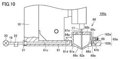
- FIG. 10 is a partial cross-sectional view showing a coating unit 100a according to the fourth modification when the coating needle 17 is lowered.
- 11 is a bottom view of the container 68 shown in FIG.
- FIG. 12 is a plan view of the support portion 61 shown in FIG.
- the application unit 100a includes a container 68 instead of the container 18 as compared to the application unit 100 described above, and a support 61 for supporting the container 68. It differs only in.
- the configuration other than these points is the same as that of the coating unit 100, and thus the detailed description is omitted.
- the container 68 includes a container body 68a, a lid 68b and a weir 68c.
- the container main body 68a has, for example, a bottomed cylindrical shape whose upper end is open.
- the bottom of the container body 68a has a substantially inverted conical shape.
- a through hole 82a communicating the inside and the outside of the container 68 is formed.
- the through hole 82a can penetrate the coating needle 17 so that the tip of the coating needle 17 can be protruded downward, and the size of the liquid material L stored in the container 68 is set so as not to drip off .
- the lid 68 b is a member for closing the opening at the upper end of the container body 68 a. Similar to the lid 18b, the lid 68b has a through hole 81a through which the application needle 17 can be inserted, and a suction hole 84a for sucking outside air into the container 68 when the vacuum pump 20 is operated. It is formed.
- the weir 68c is formed along the horizontal direction on the side surface of the container body 68a.
- the container 68 is formed with a through hole 83 a for sucking the gas (air) in the container 68 by the vacuum pump 20.
- the through hole 83a extends vertically downward from the middle of the upper through hole 183a passing through in the horizontal direction from the inner surface 68d of the container body 68a to the outer peripheral surface of the weir 68c, and opens in the lower surface 68e of the weir 68c. It is comprised from the lower side through-hole 183b.
- the opening of the outer peripheral surface of the weir 68 c in the upper through hole 183 a is closed by a screw 69. Therefore, the through hole 83a constitutes an L-shaped passage that opens to the inner surface 68d of the container body 68a and the lower surface 68e of the weir 68c.
- the support 61 is attached to the base 10.
- the support portion 61 may be integrally formed with the base 10.
- the support portion 61 has a plate shape and is disposed along the horizontal direction.
- the supporting portion 61 is formed with a hole 61a through which a portion of the container body 68a below the ridge 68c can be inserted.
- a groove 61b opened on the upper surface 61d is annularly formed.
- a through hole 61c which is connected to the groove 61b and extends in the horizontal direction is formed.
- the suction tube 19 is connected to the support portion 61 so as to communicate with the through hole 61 c.
- a vacuum pump 20, a pressure sensor 21, and a pressure control valve 22 are attached to the suction tube 19.
- the support portion 61 supports the container 68 by being in contact with the lower surface 68 e of the collar 68 c in a state where the lower portion of the container main body 68 a is inserted into the hole 61 a.
- the groove 61 b is covered by the weir 68 c and communicates with the lower through hole 183 b of the through hole 83 a formed in the container 68.
- the upper through holes 183a, the lower through holes 183b, the grooves 61b, and the through holes 61c form a flow path of gas drawn from the inside of the container 68.
- the container 68 can be easily desorbed, and by inserting the container body 68 a into the hole 61 a of the support portion 61, the flow path of the gas sucked from the inside of the container 68 is easy. Is formed.
- the container 68 When the container 68 is supported by the support portion 61, it is preferable to provide a gap between the outer peripheral surface of the container body 68a and the inner peripheral surface of the hole 61a of the support portion 61. As a result, the container body 68 a can be easily inserted into the hole 61 a of the support portion 61. Furthermore, even if the attachment position of the application needle 17 is displaced, the container 68 can be moved in the horizontal direction within the range of the gap according to the positional deviation of the application needle 17. As a result, the application needle 17 and the through holes 81a and 82a can be positioned at appropriate relative positions, and the application amount of the liquid material L from the container 68 can be stabilized.
- the width of the groove 61b is larger than the diameter of the lower through hole 183b so that the lower through hole 183b formed in the weir 68c communicates with the groove 61b. It is set large.
- a vacuum ejector having a maximum negative pressure of about ⁇ 80 kPa may be used instead of the vacuum pump 20, a vacuum ejector having a maximum negative pressure of about ⁇ 80 kPa may be used.
- the diameter of the suction hole 84a it is preferable to set the diameter of the suction hole 84a to 1/3 or less of the diameter of the through hole 83a.
- the diameter of the lower through hole 183b is set to the diameter of the upper through hole 183a in consideration of the positional deviation of the lower through hole 183b with respect to the upper through hole 183a. It may be set smaller than that.
- the diameter of the suction hole 84a be 1/3 or less of the diameter of the lower through hole 183b of the upper through hole 183a and the lower through hole 183b, whichever has the smaller diameter.
Landscapes
- Coating Apparatus (AREA)
Abstract
塗布ユニットは、底に貫通孔(82)が形成され、液体材料(L)が注入された容器(18)と、貫通孔(82)から突出することにより、液体材料(L)を対象物に塗布する塗布針(17)と、容器(18)内を負圧にするための真空ポンプ(20)とを備える。これにより、液体材料を長時間安定して塗布することが可能となる。
Description
本発明は、塗布針を用いて対象物に液体材料を塗布するための塗布ユニットおよび塗布装置に関する。
RFID(Radio Frequency Identifier)タグなどの微細な回路を印刷(塗布)方式で形成するプリンテッドエレクトロニクス技術が急速に発展してきている。微細なパターンを形成する方式としては、印刷方式、インクジェット方式などが一般的であるが、塗布針を用いた方式も、広範囲の粘度の材料を用いて微細な塗布が可能な点で、その選択肢の一つである。
塗布針を用いて微細な塗布を行う方法として、特開2007-268353号公報(特許文献1)に記載のような塗布ユニットを用いて行う方法がある。当該塗布ユニットでは、液体材料が容器に収容される。容器には、液体材料を収容している内部空間の下方に、塗布針を挿通可能な貫通孔が形成される。
上記の塗布ユニットは、塗布針の先端が容器内において液体材料に浸漬されている第1状態と、塗布針の先端が容器に形成された貫通孔から下方に突出して対象物に液体材料を塗布可能な第2状態とを取り得る。
図7は、従来の塗布ユニットにおける塗布針の状態変化を示す図である。図7において、(a)は第1状態を示し、(b)は第2状態を示す。(c)は、液体材料Lの粘度が低いときにおける、第1状態と第2状態との切り替えを繰り返し行なった後の第1状態を示す。(d)は、液体材料Lの粘度が高いときにおける、第1状態と第2状態との切り替えを繰り返し行なった後の第1状態を示す。
図7(b)に示されるように、塗布針117が容器118の貫通孔182から突出することにより、塗布針117の周囲に付着する液体材料Lが貫通孔182から出て、対象物140に塗布される。液体材料Lの粘度が低い場合、図7(c)に示されるように、塗布針117の先端が容器118内に移動するのに伴い、塗布針117の周囲を付着した液体材料Lも容器118内に戻る。しかしながら、液体材料Lがたとえば金属粉を分散させた高粘度の導電性材料である場合、第1状態と第2状態との切り替えを複数回繰り返すと、図7(d)に示されるように、容器118の外周面における貫通孔182の周囲の領域上、および貫通孔182の下方に、液体材料Lの溜り部50が形成される。当該液体材料Lの溜り部50は、塗布針117の先端が容器118内に移動しているのにかかわらず、貫通孔182から液体材料Lが突出したままになることにより形成される。金属粉を分散させた高粘度の導電性材料の場合、液体材料Lの比重が大きく、かつ流動性が低いために、上記のような溜り部50が形成される。
液体材料Lの溜り部50が発生すると、塗布針117の先端に付着する液体材料Lの量が変化し、対象物140に塗布される液体材料Lの量がばらつくため、液体材料Lを長時間安定して塗布することができない。
本発明は、上記の課題を解決するためになされたものであって、その目的は、液体材料を長時間安定して塗布することが可能な塗布ユニットおよび塗布装置を提供することである。
本開示の塗布ユニットは、底に第1貫通孔が形成され、液体材料が注入された容器と、第1貫通孔から突出することにより、液体材料を対象物に塗布する塗布針と、容器内を負圧にするための負圧源とを備える。
好ましくは、負圧源は、容器内の気体を吸引することにより容器内を負圧にする。塗布ユニットは、容器内の圧力を検出するための圧力センサと、圧力センサによって検出された圧力に基づいて、容器内の圧力が一定になるように負圧源の吸引力を制御するための制御部とをさらに備える。
好ましくは、負圧源は、容器内の気体を吸引することにより容器内を負圧にする。塗布ユニットは、第1貫通孔を撮像するためのカメラと、カメラの撮像によって得られた画像に基づいて、貫通孔からの液体材料の突出量を測定し、突出量が一定になるように負圧源の吸引力を制御するための制御部とをさらに備える。
好ましくは、容器には、負圧源によって容器内が負圧にされたときに容器内に外気を取り込むための吸入孔が形成される。
好ましくは、容器には、負圧源によって容器内の気体を吸引するための第2貫通孔が形成される。吸入孔の径は、第2貫通孔の径の1/3以下である。
好ましくは、塗布ユニットは、容器を支持するための支持部をさらに備える。容器は、容器本体と、容器本体の側面上に形成された鍔とを含む。容器には、負圧源によって容器内の気体を吸引するための第2貫通孔が形成される。第2貫通孔は、容器本体の内面と鍔の下面とに開口する。支持部には、容器本体が挿通可能な穴と、上面に開口した溝と、溝に連通する第3貫通孔とが形成される。支持部は、穴に容器本体が挿通された状態で鍔の下面と接することにより容器を支持する。溝は、容器が支持部に支持されたときに鍔によって覆われるとともに、第2貫通孔と連通する。
本開示の塗布装置は、上記の塗布ユニットを用いて、対象物に液体材料を塗布する。
本開示の塗布ユニットまたは塗布装置によれば、液体材料を長時間安定して塗布することができる。
以下、本発明の実施の形態について図面を参照しつつ説明する。なお、以下の図面において同一または相当する部分には同一の参照番号を付し、その説明は繰返さない。また、以下で説明する変形例は、適宜選択的に組み合わされてもよい。
<塗布装置の構成>
図1は、本実施の形態に係る塗布ユニットを備える塗布装置の構成を概略的に示した図である。塗布装置200は、RFIDタグなどに導電性材料をパターン描画したり、配線パターンのオープン欠陥を修正したりする。図1に示されるように、塗布装置200は、塗布ユニット100と、観察光学系110と、観察光学系110に接続されたCCDカメラ111と、Z軸テーブル120と、X軸テーブル121と、Y軸テーブル122と、基台123と、操作パネル131と、モニタ132と、制御用コンピュータ133とを含む。
図1は、本実施の形態に係る塗布ユニットを備える塗布装置の構成を概略的に示した図である。塗布装置200は、RFIDタグなどに導電性材料をパターン描画したり、配線パターンのオープン欠陥を修正したりする。図1に示されるように、塗布装置200は、塗布ユニット100と、観察光学系110と、観察光学系110に接続されたCCDカメラ111と、Z軸テーブル120と、X軸テーブル121と、Y軸テーブル122と、基台123と、操作パネル131と、モニタ132と、制御用コンピュータ133とを含む。
観察光学系110は、対象物140(たとえば基板)の塗布位置を観察するために設けられる。CCDカメラ111は、観察光学系110により観察された画像を電気信号に変換する。塗布ユニット100は、液体材料を対象物140に塗布する。
観察光学系110、CCDカメラ111および塗布ユニット100は、Z軸テーブル120の移動体に搭載される。これにより、観察光学系110、CCDカメラ111および塗布ユニット100は、Z軸テーブル120によって図1中のZ軸方向に移動可能に支持される。Z軸テーブル120は、X軸テーブル121の移動体に搭載される。これにより、Z軸テーブル120は、X軸テーブル121によって図1中のX軸方向に移動可能に支持される。対象物140は、Y軸テーブル122に載置される。Y軸テーブル122は、図1中のY軸方向に移動可能に設けられる。これにより、対象物140は、Y軸テーブル122によってY軸方向に移動可能に支持される。Y軸テーブル122は、基台123の上面に設置される。なお、図1中のZ軸方向は重力方向に沿う方向である。
制御用コンピュータ133は、塗布ユニット100、観察光学系110、Z軸テーブル120、X軸テーブル121、およびY軸テーブル122を制御する。操作パネル131は、制御用コンピュータ133への指令を入力するために用いられる。モニタ132は、観察光学系110のCCDカメラ111で変換された画像データおよび、制御用コンピュータ133からの出力データを表示する。
<塗布ユニットの構成>
図2~図5を参照して、塗布ユニット100の構成について説明する。図2は、塗布ユニット100の正面図である。図3は、塗布ユニット100の側面図である。図4は、塗布ユニット100が備える容器18とその周辺構成との平面図である。図5は、塗布ユニット100が備える容器18とその周辺構成とを示す部分断面図である。
図2~図5を参照して、塗布ユニット100の構成について説明する。図2は、塗布ユニット100の正面図である。図3は、塗布ユニット100の側面図である。図4は、塗布ユニット100が備える容器18とその周辺構成との平面図である。図5は、塗布ユニット100が備える容器18とその周辺構成とを示す部分断面図である。
塗布ユニット100は、ベース台10と、サーボモータ11と、カム12と、軸受13と、カム連結板14と、可動部15と、塗布針ホルダ16と、当該塗布針ホルダ16に支持された塗布針17と、容器18と、吸引チューブ19と、真空ポンプ20と、圧力センサ21と、圧力制御弁22と、制御装置23とを主に備える。
サーボモータ11は、図1に示したZ軸方向に沿った方向に回転軸が延びるようにベース台10に設置されている。サーボモータ11の回転軸にはカム12が接続されている。カム12は、サーボモータ11の回転軸を中心として回転可能である。カム12の下面12bは、サーボモータ11の回転軸に垂直な平面である。カム12の上面12aは、カム12の下面に対して傾斜している。つまり、カム12の上面12aは、サーボモータ11の回転軸に垂直な平面に対して傾斜している。
軸受13は、カム12の上面12aに接するように配置されている。軸受13は、図2に示すようにカム12から見て特定の方向(サーボモータ11の右側)に配置される。軸受13は、サーボモータ11の回転軸が回転することでカム12が回転したとき、カム12の上面12aに接触した状態を保つ。この軸受13にカム連結板14が接続される。カム連結板14において、軸受13と接続された一方端と反対側の他方端は、可動部15に固定される。可動部15には、塗布針ホルダ固定部24および塗布針ホルダ収納部25が接続される。
塗布針ホルダ16は、塗布針17を支持し、塗布針ホルダ収納部25に着脱可能に収納される。言い換えると、塗布針17は、塗布針ホルダ16を介して塗布針ホルダ収納部25に着脱可能である。塗布針17は、塗布針ホルダ16の下面(サーボモータ11が位置する側と反対側である下側)において塗布針ホルダ16から突出するように配置される。塗布針ホルダ16の下には容器18が配置されている。塗布針17は、容器18に挿入された状態で支持される。
可動部15には固定ピン26が設置される。さらに、サーボモータ11を保持しているベース台10には別の固定ピン27が設置される。この固定ピン26、27の間を繋ぐようにバネ28が設置される。バネ28により、可動部15は容器18側に向けた引張り力を受けた状態になっている。バネ28による引張り力は、可動部15およびカム連結板14を介して軸受13に作用する。バネ28の引張り力によって、軸受13は、カム12の上面12aに押圧された状態を維持する。
可動部15、塗布針ホルダ固定部24および塗布針ホルダ収納部25は、ベース台10に設置されたリニアガイド29に沿って移動する。リニアガイド29は、Z軸方向に延びるように配置される。そのため、可動部15、塗布針ホルダ固定部24および塗布針ホルダ収納部25は、Z軸方向に沿って移動可能である。
上述したように、カム12の上面12aは、サーボモータ11の回転軸に垂直な平面に対して傾斜している。そのため、サーボモータ11の回転軸が回転することでカム12が回転すると、カム12の上面12aに押圧された軸受13は、サーボモータ11の回転軸に沿って上下移動する。軸受13の上下移動に伴なって、カム連結板14,可動部15,塗布針ホルダ固定部24,塗布針ホルダ収納部25および塗布針ホルダ16を介して軸受13に間接的に接続された塗布針17もサーボモータ11の回転軸に沿って上下移動する。すなわち、サーボモータ11の回転運動は、カム12を介して塗布針17の上下方向の直線運動に変換される。ここで、塗布針17が取り得る最も高い位置を「第1位置」といい、最も低い位置を「第2位置」という。
容器18は、ベース台10に支持される。容器18は、たとえば図示しない磁石を含み、当該磁石とベース台10の磁石との間に生じる磁力によってベース台10に対し着脱可能に支持される。容器18の内部には、液体材料Lが注入されるための空間が形成されている。液体材料Lは、たとえば金属粉を分散させた高粘度の導電性材料である。容器18は、上端が大きく開口した容器本体18aと容器本体18aの上端の開口を閉じるための蓋18bとを含む。
蓋18bには、塗布針17が挿通可能な貫通孔81が形成されている。塗布針17の先端は、貫通孔81を貫通して、容器18内に貯留された液体材料Lに浸漬される。
容器本体18aの底部は、略逆円錐状である。容器本体18aの底部の下端には、容器18の内部と外部とを連通する貫通孔82が形成されている。貫通孔82は、塗布針17を貫通させて下方へ向けて塗布針17の先端を突出させることができ、かつ、容器18に貯留された液体材料Lが垂れ落ちない大きさに設定されている。貫通孔82の孔軸は、貫通孔81の孔軸と一致する。塗布針17が第1位置に位置しているときの当該塗布針17の先端位置と、塗布針17が第2位置に位置しているときの当該塗布針17の先端位置との間に貫通孔82が位置するように、容器本体18aは配置される。これにより、サーボモータ11の回転軸の回転に伴って、塗布ユニット100は、塗布針17の先端が容器18の内部の空間に位置する第1状態と、塗布針17の先端が貫通孔82から突出した第2状態とを取り得る。
容器本体18aの側壁にも、容器18の内部と外部とを連通する貫通孔83が形成されている。貫通孔83は、容器18の内部の気体(空気)を吸引するために使用される。そのため、液体材料Lは、貫通孔83よりも液面が低くなるとともに、第1位置に位置している塗布針17の先端位置よりも液面が高くなるように、容器18の内部の空間に注入される。これにより、液体材料Lが貫通孔83から外部に吸引されることを防ぐことができる。さらに、塗布針17が第1位置に位置しているとき、塗布針17の先端を液体材料Lに浸漬させることができる。
蓋18bには、貫通孔81とは別に、容器18の内部と外部とを連通する吸入孔84が形成されている。吸入孔84は、外部の空気を容器18の内部に吸入するために使用される。
吸引チューブ19は、内部の空間が貫通孔83に連続するように、一方端が容器本体18aに接続される。吸引チューブ19の他方端には真空ポンプ20が接続される。真空ポンプ20を動作させることにより、容器18内の気体(空気)が吸引チューブ19を介して吸引され、容器18内が負圧状態となる。
圧力センサ21は、吸引チューブ19に取り付けられ、吸引チューブ19内の圧力(気圧)を測定する。圧力制御弁22は、吸引チューブ19に取り付けられ、吸引チューブ19内の気体の流量を調整する。圧力制御弁22の開閉状態によって、真空ポンプ20による吸引力が制御される。
制御装置23は、容器18内の圧力を制御する。制御装置23は、制御部231と記憶部232とを含む。記憶部232には、容器18内の圧力の目標値が予め格納されている。制御部231は、圧力センサ21による測定値と記憶部232が記憶する目標値とを比較し、比較結果に応じて圧力制御弁22の開閉状態を制御することにより、容器18内の圧力を目標値付近に安定させる。具体的には、制御部231は、圧力センサ21の測定値と目標値との差分が所定範囲内である場合には、圧力制御弁22の開閉状態を変更しない。制御部231は、圧力センサ21の測定値と目標値との差分が所定範囲外であり、かつ測定値が目標値よりも大きい場合には、圧力制御弁22の開閉状態を開方向側に制御する。これにより、真空ポンプ20の吸引力が大きくなり、容器18内の圧力が目標値に近づくように減圧される。制御部231は、圧力センサ21の測定値と目標値との差分が所定範囲外であり、かつ測定値が目標値よりも小さい場合には、圧力制御弁22の開閉状態を閉方向側に制御する。これにより、真空ポンプ20の吸引力が小さくなり、容器18内の圧力が目標値に近づくように大きくなる。なお、記憶部232が記憶する目標値は、容器18の容積、液体材料Lの粘度、および液体材料Lの残量等により適宜設定される。
制御部231は、たとえばCPU(Central Processing Unit)と、ROM(Read Only Memory)と、RAM(Random Access Memory)とによって構成される。なお、これらの部位は、内部バスを介して互いに接続される。CPUは、ROMに格納されているプログラムをRAMなどに展開して実行する。ROMに格納されるプログラムは、制御部231の処理方法が記されたプログラムである。記憶部232は、たとえば不揮発性メモリである。
<利点>
以上のように、本実施の形態の塗布ユニット100は、底に貫通孔82が形成され、液体材料Lが注入された容器18と、貫通孔82から突出することにより、液体材料Lを対象物に塗布する塗布針17と、容器18内を負圧にするための真空ポンプ(負圧源)20とを備える。
以上のように、本実施の形態の塗布ユニット100は、底に貫通孔82が形成され、液体材料Lが注入された容器18と、貫通孔82から突出することにより、液体材料Lを対象物に塗布する塗布針17と、容器18内を負圧にするための真空ポンプ(負圧源)20とを備える。
上記の構成によれば、負圧源により容器18内が負圧に保たれる。そのため、塗布針17が貫通孔82から突出することにより容器18の外部に出たものの対象物140に塗布されなかった液体材料Lは、塗布針17が容器18内に戻ったときに、容器18内に吸い込まれる。これにより、図7(d)に示されるような液体材料Lの溜り部50が容器18の貫通孔82の外部に形成されることを抑制できる。その結果、塗布針17が貫通孔82から突出するときに塗布針17の先端に付着する液体材料Lの量が安定し、液体材料が金属粉を分散させた高粘度材料であっても、液体材料を長時間安定して塗布することができる。
一般に、塗布針により液体材料を対象物に塗布する際には、塗布針の外周面に付着した液体材料が表面張力によって塗布針の上部に引き上がるまで待ってから、塗布針の先端の略平坦部に付着した液体材料を対象物に塗布(転写)する。上記の構成によれば、図7(d)に示されるような液体材料Lの溜り部50の形成が抑制されるため、が塗布針17が貫通孔82から突出するときに、塗布針17の外周面に付着する余分な液体材料Lの量を抑制できる。そのため、液体材料Lが表面張力で塗布針17の上部に引き上がるまでの待ち時間が短くなり、塗布に要する時間を短縮することができる。
真空ポンプ20は、容器18内の気体を吸引することにより容器18内を負圧にする負圧源である。塗布ユニット100は、容器18内の圧力を検出するための圧力センサ(圧力検出器)21と、圧力センサ21によって検出された圧力に基づいて、容器18内の圧力が一定になるように真空ポンプ20の吸引力を制御するための制御部231とをさらに備える。これにより、容器18内の圧力が一定に保たれ、液体材料をより安定して塗布することができる。
容器18には、真空ポンプ20によって容器18内が負圧にされたときに容器18内に外気を取り込むための吸入孔84が形成される。これにより、真空ポンプ20によって容器18内の空気を吸い込むときに、吸入孔84から外気が容器18内に取り込まれる。その結果、容器18内の圧力が低下しすぎることを抑制でき、容器18内の圧力を連続して略一定に保つことができる。容器18内の圧力が低下しすぎると、貫通孔82から液体材料Lが容器18の内側に完全に吸い込まれて、塗布針17が貫通孔82から突出するときに塗布針17の先端に付着する液体材料Lの量が少なくなる。しかしながら、上記の構成によって容器18内の圧力が低下しすぎることを抑制され、塗布針17が貫通孔82から突出するときに塗布針17の先端に付着する液体材料Lの量を一層安定させることができる。
<変形例1>
上記の説明では、圧力センサ21を用いて真空ポンプ20の吸引力を制御したが、別の方法を用いて真空ポンプ20の吸引力を制御してもよい。図6は、変形例に係る塗布ユニットの容器とその周辺構成とを示す部分断面図である。図6に示されるように、変形例に係る塗布ユニットは、上記の塗布ユニット100と比較して、圧力センサ21および制御装置23の代わりに、カメラ30および制御装置23aを備える点で相違する。
上記の説明では、圧力センサ21を用いて真空ポンプ20の吸引力を制御したが、別の方法を用いて真空ポンプ20の吸引力を制御してもよい。図6は、変形例に係る塗布ユニットの容器とその周辺構成とを示す部分断面図である。図6に示されるように、変形例に係る塗布ユニットは、上記の塗布ユニット100と比較して、圧力センサ21および制御装置23の代わりに、カメラ30および制御装置23aを備える点で相違する。
カメラ30は、たとえばCCD(Charge-Coupled Device)イメージセンサによって構成され、容器18の貫通孔82およびその周辺とを撮像する。カメラ30は、塗布針17による1回の塗布処理が行なわれるたびに撮像する。
制御装置23aは、カメラ30の撮像により得られた画像データに基づいて、圧力制御弁22の開閉状態を制御する。制御装置23aは、制御部233と、記憶部234とを備える。
制御部233は、カメラ30が撮像を行なうたびに当該撮像により得られた画像データを取得する。制御部233は、画像データに対して画像処理を行ない、貫通孔82から突出する液体材料Lの貫通孔82からの突出量を算出する。たとえば、制御部233は、画像データに対してエッジ抽出処理を行ない、液体材料Lの表面を特定し、貫通孔82から当該表面までの距離を突出量として算出する。制御部233は、各画像データに対して、当該画像データの撮像順を識別する識別情報と、当該画像データから算出した突出量とを対応付けて記憶部234に格納する。識別情報は、たとえば撮像順を示す番号または撮像日時である。
制御部233は、最新の画像データから算出した突出量が所定範囲内か否かを判断する。最新の画像データから算出した突出量が所定範囲外である場合、制御部233は、当該突出量と過去の突出量とを比較する。ここで、過去の突出量とは、前回の画像データから算出した突出量であってもよいし、過去の複数回の画像データから算出した突出量の平均値であってもよい。最新の画像データから算出した突出量が所定範囲の上限値を超え、かつ最新の突出量が過去の突出量よりも大きい場合、制御部233は、圧力制御弁22の開閉状態を開方向側に制御する。これにより、容器18内がさらに減圧され、液体材料Lの貫通孔82からの突出量が減少する。
最新の画像データから算出した突出量が所定範囲の下限値未満であり、かつ最新の突出量が過去の突出量よりも小さい場合、制御部233は、圧力制御弁22の開閉状態を閉方向側に制御する。これにより、容器18内の圧力が小さくなりすぎることを抑制できる。
最新の画像データから算出した突出量が所定範囲内である場合、制御部233は、圧力制御弁22の開閉状態を変更しない。最新の画像データから算出した突出量が所定範囲の上限値を超えるが、最新の突出量が過去の突出量以下の場合も、制御部233は、圧力制御弁22の開閉状態を変更しない。さらに、最新の画像データから算出した突出量が所定範囲の下限値未満であるが、最新の突出量が過去の突出量以上の場合も、制御部233は、圧力制御弁22の開閉状態を変更しない。
これにより、貫通孔82からの液体材料Lの突出量が安定するため、塗布針17が貫通孔82から突出するときに塗布針17の先端に付着する液体材料Lの量がより安定する。その結果、液体材料Lを長時間より安定して塗布することができる。
なお、上記の説明では、制御部233は、最新の画像データから算出した突出量と所定範囲との比較結果および最新の画像データから算出した突出量と過去の突出量との比較結果の両方に基づいて、圧力制御弁22の開閉状態を制御した。しかしながら、制御部233は、最新の画像データから算出した突出量と所定範囲との比較結果および最新の画像データから算出した突出量と過去の突出量との比較結果のいずれか一方に基づいて、圧力制御弁22の開閉状態を制御してもよい。
制御部233は、制御部231と同様に、たとえばCPUと、ROMと、RAMとによって構成される。記憶部234は、記憶部232と同様に、たとえば不揮発性メモリである。
<変形例2>
上記の説明では、容器18内の負圧状態にするための貫通孔83を容器本体18aの側壁に形成するものとしたが、貫通孔83は蓋18bに形成されてもよい。逆に、吸入孔84を蓋18bに形成するものとしたが、吸入孔84は容器本体18aの側壁に形成されてもよい。
上記の説明では、容器18内の負圧状態にするための貫通孔83を容器本体18aの側壁に形成するものとしたが、貫通孔83は蓋18bに形成されてもよい。逆に、吸入孔84を蓋18bに形成するものとしたが、吸入孔84は容器本体18aの側壁に形成されてもよい。
<変形例3>
上記の説明では、容器18内を負圧にするための負圧源として真空ポンプ20を用いるものとした。しかしながら、負圧源は、真空ポンプ20に限定されるものではなく、他の装置であってもよい。たとえば、既存の圧縮空気設備を利用した真空エジェクタを用いてもよい。これにより、コンパクトな塗布ユニットを安価に製造することができる。
上記の説明では、容器18内を負圧にするための負圧源として真空ポンプ20を用いるものとした。しかしながら、負圧源は、真空ポンプ20に限定されるものではなく、他の装置であってもよい。たとえば、既存の圧縮空気設備を利用した真空エジェクタを用いてもよい。これにより、コンパクトな塗布ユニットを安価に製造することができる。
真空エジェクタにより得られる最高負圧圧力は、一般的に-80kPa程度であり、真空ポンプに比べて絶対値が小さい。そのため、吸入孔84の径が貫通孔83の径よりも大きい場合には、吸入孔84から容器18内への外気の流量が貫通孔83から吸引される気体の流量と同程度となり、容器18内を十分に負圧状態にすることができない。したがって、負圧源として最高負圧圧力が-80kPa程度の真空エジェクタを用いる場合、吸入孔84の径は、負圧源によって容器18内の気体を吸引するための貫通孔83の径の1/3以下であることが好ましい。ここで、貫通孔83の径とは、貫通孔83のうちの最小径を意味する。真空エジェクタを動作させたときの貫通孔83の気体の流量は、貫通孔83の最も狭い箇所で決定されるからである。
図8は、吸入孔84の径と貫通孔83の径との比率γ(=(吸入孔84の径)/(貫通孔83の径))を変化させたときの、負圧源の設定負圧と容器18の貫通孔82からの液体材料Lの突出量(mm)との関係を示す図である。図8には、容器18の貫通孔82から突出量1mmだけ突出した液体材料Lの溜まり部を形成した状態から設定負圧の絶対値を上昇させたときの突出量の変化が示される。負圧源として、最高負圧圧力が-80kPaの真空エジェクタを用いている。
図8に示されるように、比率γ=0.5以下では、真空エジェクタの設定負圧を最高値まで上げたとしても、液体材料Lの突出量に変化が見られなかった。これに対し、比率γ=0.33以下では、設定負圧を上げることにより突出量が減少した。この結果から、吸入孔84の径を貫通孔83の径の1/3以下にすることが好ましい。
<変形例4>
上記の説明では、容器18は、磁力によってベース台10に対し着脱可能に支持されるものとした。しかしながら、ベース台10による容器の支持方法はこれに限定されない。
上記の説明では、容器18は、磁力によってベース台10に対し着脱可能に支持されるものとした。しかしながら、ベース台10による容器の支持方法はこれに限定されない。
図9~図12を参照して、変形例4に係る塗布ユニット100aを説明する。図9は、変形例4に係る塗布ユニット100aを示す部分断面図である。図9には、塗布針17が最も高い位置に位置しているときの塗布ユニット100aが示される。図10は、塗布針17を下降させたときの変形例4に係る塗布ユニット100aを示す部分断面図である。図11は、図9に示される容器68の底面図である。図12は、図9に示される支持部61の平面図である。
図9および図10に示されるように、塗布ユニット100aは、上記の塗布ユニット100と比較して、容器18の代わりに容器68を備えるとともに、容器68を支持するための支持部61を備える点でのみ相違する。これらの点以外の構成については、塗布ユニット100と同様であるため、詳細な説明を省略する。
容器68は、容器本体68aと、蓋68bと、鍔68cとを含む。容器本体68aは、たとえば上端が開口した有底円筒形状である。容器本体68aの底部は、略逆円錐形である。容器本体68aの底部の下端には、容器本体18aと同様に、容器68の内部と外部とを連通する貫通孔82aが形成されている。貫通孔82aは、塗布針17を貫通させて下方へ向けて塗布針17の先端を突出させることができ、かつ、容器68に貯留された液体材料Lが垂れ落ちない大きさに設定されている。
蓋68bは、容器本体68aの上端の開口を閉じるための部材である。蓋68bには、上記の蓋18bと同様に、塗布針17が挿通可能な貫通孔81aと、真空ポンプ20を動作させたときに外気を容器68の内部に吸入するための吸入孔84aとが形成される。鍔68cは、容器本体68aの側面上に水平方向に沿って形成される。
容器68には、真空ポンプ20によって容器68内の気体(空気)を吸引するための貫通孔83aが形成されている。貫通孔83aは、容器本体68aの内面68dから鍔68cの外周面まで水平方向に貫通する上側貫通孔183aと、上側貫通孔183aの途中から鉛直方向下向きに延び、鍔68cの下面68eに開口する下側貫通孔183bとから構成される。上側貫通孔183aにおける鍔68cの外周面の開口は、ねじ69によって閉じられている。そのため、貫通孔83aは、容器本体68aの内面68dと、鍔68cの下面68eとに開口するL字状の通路を構成する。
支持部61は、ベース台10に取り付けられる。もしくは、支持部61は、ベース台10と一体に形成されてもよい。支持部61は、板状であり、水平方向に沿って配置される。支持部61には、容器本体68aにおける鍔68cよりも下方の部分が挿通可能な穴61aが形成されている。支持部61の穴61aの周囲には、上面61dに開口した溝61bが環状に形成されている。さらに支持部61には、溝61bと接続し、水平方向に延びる貫通孔61cが形成されている。貫通孔61cに連通するように、支持部61に吸引チューブ19が接続される。なお、上記と同様に、吸引チューブ19には、真空ポンプ20、圧力センサ21、圧力制御弁22が取り付けられている。
支持部61は、穴61aに容器本体68aの下部が挿通された状態で鍔68cの下面68eと接することにより、容器68を支持する。このとき、溝61bは、鍔68cによって覆われるとともに、容器68に形成された貫通孔83aの下側貫通孔183bと連通する。これにより、上側貫通孔183a、下側貫通孔183b、溝61bおよび貫通孔61cは、容器68の内部から吸引される気体の流路を構成する。本変形例によれば、容器68の脱着を容易に行なうことができるとともに、容器本体68aを支持部61の穴61aに挿入することにより、容器68の内部から吸引される気体の流路が容易に形成される。
容器68が支持部61によって支持されるとき、容器本体68aの外周面と支持部61の穴61aの内周面との間に隙間を設けることが好ましい。これにより、容器本体68aを支持部61の穴61aに挿入しやすくなる。さらに、塗布針17の取り付け位置がずれた場合であっても、塗布針17の位置ずれに応じて、容器68を水平方向に隙間分の範囲内で移動することができる。その結果、塗布針17と貫通孔81a,82aとを適切な相対位置に位置させ、容器68からの液体材料Lの塗布量を安定化することができる。容器68を水平方向に隙間分だけ移動させたとしても、鍔68cに形成された下側貫通孔183bが溝61bと連通するように、溝61bの幅は、下側貫通孔183bの径よりも大きく設定されている。
本変形例4においても、変形例3と同様に、真空ポンプ20の代わりに、最高負圧圧力がー80kPa程度の真空エジェクタを用いてもよい。この場合、吸入孔84aの径を貫通孔83aの径の1/3以下にすることが好ましい。上側貫通孔183aを形成した後に下側貫通孔183bを形成する場合、上側貫通孔183aに対する下側貫通孔183bの位置ずれを考慮して、下側貫通孔183bの径を上側貫通孔183aの径よりも小さく設定してもよい。この場合、吸入孔84aの径は、上側貫通孔183aおよび下側貫通孔183bのうち径が小さい方の下側貫通孔183bの径の1/3以下にすることが好ましい。
今回開示された実施の形態は、すべての点で例示であって制限的なものではないと考えられるべきである。本発明の範囲は、上記した実施の形態の説明でなくて請求の範囲によって示され、請求の範囲と均等の意味および範囲内でのすべての変更が含まれることが意図される。
10 ベース台、11 サーボモータ、12 カム、12a,61d 上面、12b,68e 下面、13 軸受、14 カム連結板、15 可動部、16 塗布針ホルダ、17,117 塗布針、18,68,118 容器、18a,68a 容器本体、18b,68b 蓋、19 吸引チューブ、20 真空ポンプ、21 圧力センサ、22 圧力制御弁、23,23a 制御装置、24 塗布針ホルダ固定部、25 塗布針ホルダ収納部、26,27 固定ピン、28 バネ、29 リニアガイド、30 カメラ、50 溜り部、61 支持部、61a 穴、61b 溝、61c,81,81a,82,82a,83,83a,182 貫通孔、68c 鍔、68d 内面、69 ねじ、84,84a 吸入孔、100 塗布ユニット、110 観察光学系、111 CCDカメラ、120 Z軸テーブル、121 X軸テーブル、122 Y軸テーブル、123 基台、131 操作パネル、132 モニタ、133 制御用コンピュータ、140 対象物、183a 上側貫通孔、183b 下側貫通孔、200 塗布装置、231,233 制御部、232,234 記憶部。
Claims (7)
- 底に第1貫通孔が形成され、液体材料が注入された容器と、
前記第1貫通孔から突出することにより、前記液体材料を対象物に塗布する塗布針と、
前記容器内を負圧にするための負圧源とを備える、塗布ユニット。 - 前記負圧源は、前記容器内の気体を吸引することにより前記容器内を負圧にし、
前記塗布ユニットは、
前記容器内の圧力を検出するための圧力センサと、
前記圧力センサによって検出された圧力に基づいて、前記容器内の圧力が一定になるように前記負圧源の吸引力を制御するための制御部とをさらに備える、請求項1に記載の塗布ユニット。 - 前記負圧源は、前記容器内の気体を吸引することにより前記容器内を負圧にし、
前記塗布ユニットは、
前記第1貫通孔を撮像するためのカメラと、
前記カメラの撮像によって得られた画像に基づいて、前記第1貫通孔からの前記液体材料の突出量を測定し、前記突出量が一定になるように前記負圧源の吸引力を制御するための制御部とをさらに備える、請求項1に記載の塗布ユニット。 - 前記容器には、前記負圧源によって前記容器内が負圧にされたときに前記容器内に外気を取り込むための吸入孔が形成される、請求項1~3のいずれか1項に記載の塗布ユニット。
- 前記容器には、前記負圧源によって前記容器内の気体を吸引するための第2貫通孔が形成され、
前記吸入孔の径は、前記第2貫通孔の径の1/3以下である、請求項4に記載の塗布ユニット。 - 前記容器を支持するための支持部をさらに備え、
前記容器は、容器本体と、前記容器本体の側面上に形成された鍔とを含み、
前記容器には、前記負圧源によって前記容器内の気体を吸引するための第2貫通孔が形成され、
前記第2貫通孔は、前記容器本体の内面と前記鍔の下面とに開口し、
前記支持部には、前記容器本体が挿通可能な穴と、上面に開口した溝と、前記溝に連通する第3貫通孔とが形成され、
前記支持部は、前記穴に前記容器本体が挿通された状態で前記鍔の前記下面と接することにより前記容器を支持し、
前記溝は、前記容器が前記支持部に支持されたときに前記鍔によって覆われるとともに、前記第2貫通孔と連通する、請求項1~4のいずれか1項に記載の塗布ユニット。 - 請求項1~6のいずれか1項に記載の塗布ユニットを用いて、前記対象物に前記液体材料を塗布する、塗布装置。
Applications Claiming Priority (4)
| Application Number | Priority Date | Filing Date | Title |
|---|---|---|---|
| JP2017120597 | 2017-06-20 | ||
| JP2017-120597 | 2017-06-20 | ||
| JP2017-251032 | 2017-12-27 | ||
| JP2017251032A JP6971146B2 (ja) | 2017-06-20 | 2017-12-27 | 塗布ユニットおよび塗布装置 |
Publications (1)
| Publication Number | Publication Date |
|---|---|
| WO2018235528A1 true WO2018235528A1 (ja) | 2018-12-27 |
Family
ID=64737153
Family Applications (1)
| Application Number | Title | Priority Date | Filing Date |
|---|---|---|---|
| PCT/JP2018/020340 WO2018235528A1 (ja) | 2017-06-20 | 2018-05-28 | 塗布ユニットおよび塗布装置 |
Country Status (1)
| Country | Link |
|---|---|
| WO (1) | WO2018235528A1 (ja) |
Cited By (1)
| Publication number | Priority date | Publication date | Assignee | Title |
|---|---|---|---|---|
| WO2021182613A1 (ja) * | 2020-03-13 | 2021-09-16 | Ntn株式会社 | 液体材料塗布ユニット、液体材料塗布装置および液体材料塗布方法 |
Citations (6)
| Publication number | Priority date | Publication date | Assignee | Title |
|---|---|---|---|---|
| JP2006276188A (ja) * | 2005-03-28 | 2006-10-12 | Ntn Corp | パターン修正装置およびパターン修正方法 |
| JP2006310266A (ja) * | 2005-03-28 | 2006-11-09 | Ntn Corp | 塗布ユニットおよびパターン修正装置 |
| WO2010018675A1 (ja) * | 2008-08-13 | 2010-02-18 | 株式会社アプライド・マイクロシステム | 液状物吐出装置及び方法 |
| JP2010264380A (ja) * | 2009-05-14 | 2010-11-25 | Panasonic Corp | 液体塗布方法および装置 |
| WO2016199696A1 (ja) * | 2015-06-09 | 2016-12-15 | Ntn株式会社 | 塗布ユニットおよびそれを用いた塗布装置 |
| WO2017090381A1 (ja) * | 2015-11-25 | 2017-06-01 | Ntn株式会社 | 塗布ユニット、塗布装置、被塗布対象物の製造方法および基板の製造方法 |
-
2018
- 2018-05-28 WO PCT/JP2018/020340 patent/WO2018235528A1/ja active Application Filing
Patent Citations (6)
| Publication number | Priority date | Publication date | Assignee | Title |
|---|---|---|---|---|
| JP2006276188A (ja) * | 2005-03-28 | 2006-10-12 | Ntn Corp | パターン修正装置およびパターン修正方法 |
| JP2006310266A (ja) * | 2005-03-28 | 2006-11-09 | Ntn Corp | 塗布ユニットおよびパターン修正装置 |
| WO2010018675A1 (ja) * | 2008-08-13 | 2010-02-18 | 株式会社アプライド・マイクロシステム | 液状物吐出装置及び方法 |
| JP2010264380A (ja) * | 2009-05-14 | 2010-11-25 | Panasonic Corp | 液体塗布方法および装置 |
| WO2016199696A1 (ja) * | 2015-06-09 | 2016-12-15 | Ntn株式会社 | 塗布ユニットおよびそれを用いた塗布装置 |
| WO2017090381A1 (ja) * | 2015-11-25 | 2017-06-01 | Ntn株式会社 | 塗布ユニット、塗布装置、被塗布対象物の製造方法および基板の製造方法 |
Cited By (1)
| Publication number | Priority date | Publication date | Assignee | Title |
|---|---|---|---|---|
| WO2021182613A1 (ja) * | 2020-03-13 | 2021-09-16 | Ntn株式会社 | 液体材料塗布ユニット、液体材料塗布装置および液体材料塗布方法 |
Similar Documents
| Publication | Publication Date | Title |
|---|---|---|
| WO2017090381A1 (ja) | 塗布ユニット、塗布装置、被塗布対象物の製造方法および基板の製造方法 | |
| KR101323213B1 (ko) | 유체 증착 장치 | |
| US9878391B2 (en) | Solder supply device | |
| JP6514047B2 (ja) | 塗布ユニットおよびそれを用いた塗布装置 | |
| JP6411735B2 (ja) | 塗布部材、塗布装置および塗布方法 | |
| JP6580874B2 (ja) | 液体塗布ユニットおよび液体塗布装置 | |
| WO2018235528A1 (ja) | 塗布ユニットおよび塗布装置 | |
| JP6971146B2 (ja) | 塗布ユニットおよび塗布装置 | |
| JP6560108B2 (ja) | 塗布ユニット、塗布装置、被塗布対象物の製造方法および基板の製造方法 | |
| JP5086708B2 (ja) | マスクブランクの製造方法及び塗布装置 | |
| CN107073513A (zh) | 涂布方法及涂布装置 | |
| US11897264B2 (en) | Liquid application unit and liquid application apparatus | |
| JP2018020325A (ja) | 塗布部材、塗布装置および塗布方法 | |
| JP2018034124A (ja) | 液体塗布ユニットおよび液体塗布装置 | |
| JP6587945B2 (ja) | 塗布機構、塗布装置、被塗布対象物の製造方法、および基板の製造方法 | |
| JP6716654B2 (ja) | 塗布部材、塗布装置および塗布方法 | |
| JP2009206061A (ja) | 塗布ユニットおよびそれを用いたパターン修正装置 | |
| WO2016204152A1 (ja) | 塗布装置 | |
| JP6971207B2 (ja) | 液体材料塗布機構および液体材料塗布装置 | |
| JP2016107222A (ja) | 塗布機構および塗布装置 | |
| JP7272837B2 (ja) | 液体塗布装置および液体塗布方法 | |
| KR101523093B1 (ko) | 마스크 블랭크의 제조 방법 및 도포 장치 |
Legal Events
| Date | Code | Title | Description |
|---|---|---|---|
| 121 | Ep: the epo has been informed by wipo that ep was designated in this application |
Ref document number: 18820088 Country of ref document: EP Kind code of ref document: A1 |
|
| NENP | Non-entry into the national phase |
Ref country code: DE |
|
| 122 | Ep: pct application non-entry in european phase |
Ref document number: 18820088 Country of ref document: EP Kind code of ref document: A1 |