WO2018235475A1 - ゴルフシャフト - Google Patents
ゴルフシャフト Download PDFInfo
- Publication number
- WO2018235475A1 WO2018235475A1 PCT/JP2018/019201 JP2018019201W WO2018235475A1 WO 2018235475 A1 WO2018235475 A1 WO 2018235475A1 JP 2018019201 W JP2018019201 W JP 2018019201W WO 2018235475 A1 WO2018235475 A1 WO 2018235475A1
- Authority
- WO
- WIPO (PCT)
- Prior art keywords
- layer
- golf shaft
- curing agent
- epoxy resin
- outer layer
- Prior art date
- Legal status (The legal status is an assumption and is not a legal conclusion. Google has not performed a legal analysis and makes no representation as to the accuracy of the status listed.)
- Ceased
Links
Images





Classifications
-
- A—HUMAN NECESSITIES
- A63—SPORTS; GAMES; AMUSEMENTS
- A63B—APPARATUS FOR PHYSICAL TRAINING, GYMNASTICS, SWIMMING, CLIMBING, OR FENCING; BALL GAMES; TRAINING EQUIPMENT
- A63B53/00—Golf clubs
- A63B53/10—Non-metallic shafts
-
- A—HUMAN NECESSITIES
- A63—SPORTS; GAMES; AMUSEMENTS
- A63B—APPARATUS FOR PHYSICAL TRAINING, GYMNASTICS, SWIMMING, CLIMBING, OR FENCING; BALL GAMES; TRAINING EQUIPMENT
- A63B53/00—Golf clubs
- A63B53/12—Metallic shafts
-
- C—CHEMISTRY; METALLURGY
- C09—DYES; PAINTS; POLISHES; NATURAL RESINS; ADHESIVES; COMPOSITIONS NOT OTHERWISE PROVIDED FOR; APPLICATIONS OF MATERIALS NOT OTHERWISE PROVIDED FOR
- C09J—ADHESIVES; NON-MECHANICAL ASPECTS OF ADHESIVE PROCESSES IN GENERAL; ADHESIVE PROCESSES NOT PROVIDED FOR ELSEWHERE; USE OF MATERIALS AS ADHESIVES
- C09J1/00—Adhesives based on inorganic constituents
-
- C—CHEMISTRY; METALLURGY
- C09—DYES; PAINTS; POLISHES; NATURAL RESINS; ADHESIVES; COMPOSITIONS NOT OTHERWISE PROVIDED FOR; APPLICATIONS OF MATERIALS NOT OTHERWISE PROVIDED FOR
- C09J—ADHESIVES; NON-MECHANICAL ASPECTS OF ADHESIVE PROCESSES IN GENERAL; ADHESIVE PROCESSES NOT PROVIDED FOR ELSEWHERE; USE OF MATERIALS AS ADHESIVES
- C09J163/00—Adhesives based on epoxy resins; Adhesives based on derivatives of epoxy resins
-
- A—HUMAN NECESSITIES
- A63—SPORTS; GAMES; AMUSEMENTS
- A63B—APPARATUS FOR PHYSICAL TRAINING, GYMNASTICS, SWIMMING, CLIMBING, OR FENCING; BALL GAMES; TRAINING EQUIPMENT
- A63B2209/00—Characteristics of used materials
- A63B2209/02—Characteristics of used materials with reinforcing fibres, e.g. carbon, polyamide fibres
-
- C—CHEMISTRY; METALLURGY
- C08—ORGANIC MACROMOLECULAR COMPOUNDS; THEIR PREPARATION OR CHEMICAL WORKING-UP; COMPOSITIONS BASED THEREON
- C08K—Use of inorganic or non-macromolecular organic substances as compounding ingredients
- C08K3/00—Use of inorganic substances as compounding ingredients
- C08K3/02—Elements
- C08K3/04—Carbon
- C08K3/041—Carbon nanotubes
-
- C—CHEMISTRY; METALLURGY
- C08—ORGANIC MACROMOLECULAR COMPOUNDS; THEIR PREPARATION OR CHEMICAL WORKING-UP; COMPOSITIONS BASED THEREON
- C08K—Use of inorganic or non-macromolecular organic substances as compounding ingredients
- C08K5/00—Use of organic ingredients
- C08K5/0008—Organic ingredients according to more than one of the "one dot" groups of C08K5/01 - C08K5/59
- C08K5/0025—Crosslinking or vulcanising agents; including accelerators
-
- C—CHEMISTRY; METALLURGY
- C08—ORGANIC MACROMOLECULAR COMPOUNDS; THEIR PREPARATION OR CHEMICAL WORKING-UP; COMPOSITIONS BASED THEREON
- C08K—Use of inorganic or non-macromolecular organic substances as compounding ingredients
- C08K5/00—Use of organic ingredients
- C08K5/16—Nitrogen-containing compounds
- C08K5/17—Amines; Quaternary ammonium compounds
Definitions
- the present invention relates to a golf shaft in which a steel base tube is coated with an outer layer of fiber reinforced plastic.
- a steel base tube is thinned and the outer side is covered with an outer layer of fiber reinforced plastic.
- Patent Document 1 the inner layer of non-woven fabric is interposed between the blank and the outer layer to improve the adhesion between the blank and the outer layer.
- Patent Document 1 the adhesion between the raw pipe and the outer layer is not sufficient, and the adhesion is compensated by polishing the surface of the raw pipe, so there is a problem that the number of manufacturing processes increases.
- the problem to be solved is that sufficient adhesion can not be obtained without polishing the surface of the blank.
- a blank made of steel, a plated layer formed on the outer periphery of the blank, and an outer layer covering the plated layer An adhesive layer is interposed between the plated layer and the outer layer to adhere the plated layer to the outer layer, and the outer layer is formed of a fiber reinforced plastic using an epoxy resin as a matrix resin,
- the adhesive layer is an epoxy resin composition containing a mixed curing agent obtained by mixing an epoxy resin and two or more amine curing agents, or a carbon nanotube resin containing an epoxy resin and at least one curing agent and dispersing carbon nanotubes
- the characteristic of the golf shaft is that it is a composition.
- the adhesive layer having high adhesion to the outer layer and the plated layer, sufficient adhesiveness between the outer layer and the hollow shell can be secured without polishing the plated layer to be the surface of the hollow shell.
- FIG. 3 is a schematic cross-sectional view of the golf shaft according to the line III-III in FIG. 2 (Example 1). It is a schematic longitudinal cross-sectional view which shows the manufacturing process of a golf shaft (Example 1). It is a development view showing a plurality of prepregs laminated (example 1). It is a graph which shows the rigid distribution of a golf shaft roughly (Example 1).
- the present invention achieves the purpose of obtaining sufficient adhesion without polishing the surface of the blank by means of an adhesive layer having high adhesion to the plated layer on the surface of the blank and the outer layer.
- the outer layer is a fiber-reinforced plastic whose matrix resin is an epoxy resin
- the adhesive layer is an epoxy resin composition containing a mixed curing agent in which the epoxy resin and two or more amine curing agents are mixed, or epoxy It was set as the carbon nanotube resin composition which disperse
- the amine curing agent can be two or more different amine curing agents selected from aliphatic polyamines, alicyclic polyamines, aromatic polyamines, and polyamidoamines. is there.
- the amine-based curing agent may be two types of triethylenetetramine and polyamidoamine, and may be blended so that the amount of polyamidoamine is larger than that of triethylenetetramine.
- the adhesive layer when the adhesive layer is a carbon nanotube resin composition, the adhesive layer may contain an epoxy resin and at least one curing agent and may be dispersed in carbon nanotubes.
- the curing agent can be an amine curing agent or an acid anhydride curing agent.
- FIG. 1 is a side view of a golf shaft, in which (A) shows the entire golf shaft and (B) shows a part of (A) in an enlarged manner.
- FIG. 2 is a schematic longitudinal sectional view of the golf shaft of FIG.
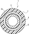
- FIG. 3 is a schematic cross-sectional view of the golf shaft along line III-III in FIG. 1 to 3 basically have the same structure although the dimensions of the respective parts do not match.
- the golf shaft 1 is formed in a tubular shape, and an axial tip 1a is a portion to which a golf club head is attached, and an axial proximal end 1b is a portion to which a golf club grip is attached.
- the golf shaft 1 of the present embodiment is configured to include a base tube 3, a plating layer 5, an outer layer 7, and an adhesive layer 9.
- the raw tube 3 is made of steel and comprises a hollow tubular shaft having a circular cross-sectional shape in the cross section.
- the raw pipe 3 of the present embodiment has a stepped shape, and is formed of a plurality of straight pipe portions 11 and a plurality of tapered pipe portions 13 connecting between the straight pipe portions 11 adjacent to each other.
- the straight pipe portion 11 is a portion in which the thickness and the diameter of the inner and outer circumferences are constant.
- the diameter of the inner and outer periphery of the straight pipe portion 11 positioned on the proximal end 3b side with respect to the straight pipe portion 11 positioned on the distal end 3a side of the raw pipe 3 is large between the adjacent straight pipe portions 11 Is getting thinner.
- the tapered tube portion 13 absorbs the difference in diameter and the difference in thickness of the adjacent straight tube portions 11, and the diameter of the inner and outer peripheries gradually increases from the tip 3a side toward the proximal end 3b.
- the wall thickness gradually decreases with The axial length of the tapered tube portion 13 is shorter than that of the straight tube portion 11.
- the outer diameter is 14.50 mm at the largest portion, and the thickness at this portion is 0.206 mm.
- the outer diameter is 8.00 mm at the smallest portion, and the thickness at this portion is 0.294 mm.
- the raw tube 3 is not limited to a stepped shape, but may be a straight shape having a constant outer diameter or a tapered shape as a whole. Further, the thickness of the raw tube 3 can be made constant or partially varied in the axial direction. Furthermore, the cross-sectional shape in the cross section of the raw tube 3 is not limited to a circle, but may be appropriately selected, such as an ellipse.
- the plated layer 5 is provided on the entire outer peripheral surface 3 c of the raw pipe 3, and constitutes the surface of the raw pipe 3.
- the plating layer 5 may be, for example, a plating of copper, nickel, chromium, zinc, tin, gold or the like, but in the present embodiment, two layers of nickel plating are laminated and then chromium plating is performed.
- the thickness of the plated layer 5 is extremely thin relative to the thickness of the blank 3 and each nickel plating is 0.005 mm and the chromium plating is 0.0003 mm, for a total of about 0.0103 mm.
- the thickness of the plating layer 5 is not limited to this.
- the outer layer 7 has a tubular shape covering the plating layer 5, and is made of a fiber reinforced plastic having an epoxy resin as a matrix resin and a fiber sheet as a reinforcing material.
- covers the whole plated layer 5 you may coat
- the outer layer 7 is formed by winding and heating a prepreg 17 (FIGS. 4 and 5), which will be described later, through the adhesive layer 9 around the raw pipe 3.
- the prepreg 17 is a fiber reinforced plastic sheet obtained by impregnating a fiber sheet with an epoxy resin containing a curing agent.
- the curing agent used for the outer layer 7 is one kind selected from aliphatic polyamines, alicyclic polyamines, aromatic polyamines, polyamidoamines and the like.
- the fiber sheet metal fibers, boron fibers, carbon fibers, glass fibers, inorganic fibers such as ceramic fibers, aramid fibers, other high-strength synthetic fibers, and the like can be used.
- Inorganic fibers are preferably used because of their light weight and high strength.
- carbon fiber is optimal because it is excellent in specific strength and specific rigidity. Therefore, in the present embodiment, a carbon fiber sheet is used as the fiber sheet.
- the outer layer 7 is formed to follow the plating layer 5 and has a stepped shape. However, since the outer layer 7 is cut at the time of manufacture of the golf shaft 1, depending on the cutting mode, in practice, the outer layer 7 is often not a stepped shape.
- the thickness of the outer layer 7 varies in the axial direction, but is set in a range thicker than the thickness of the raw pipe 3.
- the thickness of the outer layer 7 is about 0.700 mm in the thickest part and about 0.330 mm in the thinnest part.
- the thickness of the outer layer 7 may be in the range of 1.000 mm to 0.200 mm.
- the adhesive layer 9 is interposed between the plating layer 5 and the outer layer 7 and has a tubular shape for bonding between the plating layer 5 and the outer layer 7.
- the adhesive layer 9 of the present embodiment is formed following the plating layer 5 and has a stepped shape.
- the thickness of the adhesive layer 9 is substantially constant and thinner than the thicknesses of the outer layer 7 and the blank 3.
- the thickness of the adhesive layer 9 in this embodiment is about 0.02 mm.
- the thickness of the adhesive layer 9 is not limited to this, and can vary within the range in which the plated layer 5 and the outer layer 7 can be adhered.
- the adhesive layer 9 is composed of an epoxy resin composition containing a mixed curing agent in which an epoxy resin and two or more amine curing agents are mixed.
- the adhesion between the plating layer 5 and the outer layer 7 is higher than that when the plating layer 5 and the outer layer 7 are in direct contact with each other.
- a clear paint is used for the adhesive layer 9 of this embodiment.
- the adhesive layer liquid agent 15 (FIG. 4) in which the liquid epoxy resin of the clear paint and the liquid mixed curing agent are mixed in a ratio of 2: 1 is formed by curing by heating.
- the liquid epoxy resin contains 73.96% of a resin component, 25.77% of a solvent, and 0.27% of an additive.
- the liquid curing agent contains 64.82% of a resin component, 26.82% of a solvent, and 8.36% of an additive.
- the adhesive layer liquid agent 15 before curing has about 70% resin component, about 26% solvent, and about 3% additive due to the above mixing.
- the content rate of the said component is an example, and it is possible to change suitably.
- the resin component of the adhesive layer liquid agent is an epoxy resin and an amine-based curing agent.
- the amine curing agent is, for example, aliphatic polyamine, alicyclic polyamine, aromatic polyamine, polyamidoamine or the like.
- the two or more amine curing agents refer to two or more different amine curing agents selected from amine curing agents.
- two types of aliphatic polyamines triethylenetetramine and polyamidoamine are used.
- the compounding ratio at this time is set such that the amount of polyamidoamine is larger than that of triethylenetetramine.
- triethylenetetramine is about 4% with respect to polyamidoamine.
- the solvent for the adhesive layer solution is xylene, methyl iso-butyl ketone, iso-butanol, ethylene glycol monobutyl ether, toluene or the like.
- the additive of the adhesive layer solution can be a coupling agent such as silane coupling.
- FIG. 4 is a schematic cross-sectional view showing the manufacturing process of the golf shaft 1.
- the raw pipe 3 having a stepped shape and having the plated layer 5 formed on the outer peripheral surface 3c is prepared.
- an adhesive layer liquid agent 15 in which a liquid epoxy resin is mixed with a liquid curing agent is applied to the surface of the plated layer 5 of the base pipe 3.
- the application of the adhesive layer solution 15 can be performed, for example, by ironing. However, it is also possible to use other application methods such as spray coating.
- the adhesive layer liquid agent 15 is a clear paint as described above, and is a mixture of a liquid epoxy resin and a liquid mixed curing agent in a ratio of 2: 1.
- the prepreg 17 is wound around the surface of the plating layer 5 to which the adhesive layer liquid agent 15 has been applied to form a wound article 19.
- a plurality of prepregs having predetermined cutting shapes and dimensions are sequentially wound and stacked around the raw pipe 3 having the plating layer 5.
- FIG. 5 is a developed view showing a plurality of prepregs to be stacked.
- first to sixth prepregs 17a to 17f having a cutting shape and a size as shown in FIG. 5 are sequentially wound around predetermined positions in the axial direction of the raw pipe 3.
- the first prepreg 17 a is formed by bonding two prepregs in which fibers are oriented in the direction of ⁇ 45 ° with respect to the axial direction, and is wound around the entire raw tube 3 in the axial direction.
- the second prepreg 17b is formed of a single sheet of prepreg in which fibers are oriented in the axial direction, and is wound around the entire axial direction of the raw pipe 3 in the same manner as the first prepreg 17a.
- the third prepreg 17 c is made of one prepreg in which fibers are oriented in the axial direction, and is wound from the middle portion of the raw tube 3 to the proximal end 3 b.
- the third prepreg 17c is bonded to the fourth prepreg 17d.
- the fourth prepreg 17 d is made of one prepreg in which the fibers are oriented in the axial direction in the same manner as the second prepreg 17 b, and in the entire axial direction of the raw pipe 3 in a state where the third prepreg 17 c is bonded. It is wound.
- the fifth prepreg 17 e is formed of a single prepreg in which fibers are oriented in the axial direction, and is wound from the tip 3 a of the raw tube 3 to the middle portion.
- the sixth prepreg 17 f is formed of a single prepreg in which fibers are oriented in the axial direction, and is wound in the range from the tip 3 a to the middle portion, which is shorter than the fifth prepreg 17 e.
- the first to sixth prepregs 17a to 17f are wound around the raw pipe 3 in a laminated state to form the wound product 19 of FIG. 4 (C).
- the first to sixth prepregs 17a to 17f it is also possible to use a four-axis or three-axis multiaxial fabric.
- the number and shape of the layers of the prepreg 17, the winding order and the like are merely examples, and can be arbitrarily determined according to the performance of the golf club and the like.
- a tape 21 such as polypropylene for holding is wound around the outer periphery of the wound product 19 so that the wound state of the prepreg 17 is maintained.
- the wound product 19 on which the tape 21 is wound is heated in a heating furnace, and the prepreg 17 and the adhesive layer liquid agent 15 are cured to form the outer layer 7 and the adhesive layer 9.
- the tape 21 is removed, and the outer layer 7 is cut to make adjustments for obtaining desired characteristics.
- the quality can be improved.
- the golf shaft 1 in which the steel base tube 3 is covered with the outer layer 7 of fiber reinforced plastic is manufactured.
- FIG. 6 is a graph schematically showing the stiffness distribution of the golf shaft.
- the vertical axis represents bending stiffness (EI)
- the horizontal axis represents the distance from the tip.
- Steel 1, Steel 2, and Example products are all 41-inch golf shafts
- Steel 1 and Steel 2 show steel golf shafts
- Example products are steel as described above.
- the golf shaft 1 which concerns on Example 1 which wound the outer layer 7 of the fiber reinforced plastic in the element tube 3 is shown.
- the steel tube 3 is made thin, the outer layer 7 of fiber reinforced plastic is wound around the outer periphery, and this outer layer 7 is polished to be equivalent to a steel golf shaft as shown in FIG.
- the weight could be reduced to 90 g while obtaining the properties of
- FIG. 7 shows changes in stiffness distribution in the manufacturing process.
- the vertical axis indicates bending stiffness (EI)
- the horizontal axis indicates the distance from the tip.
- the raw pipe 3 of the example product is made thinner than the steel 1 and the steel 2, so that the rigidity increases substantially linearly from the distal end 3a to the proximal end 3b as shown in FIG. Raw pipe in FIG. 7).
- the weight of the raw pipe 3 at this time is 70 g in the present embodiment.
- the stiffness distribution at this time is set to be generally higher than the intended stiffness distribution (FIG. 7). Unpolished goods). Thereafter, by cutting the outer layer 7, characteristics corresponding to FIG. 6 are obtained (abraded article in FIG. 7). The weight of the golf shaft 1 at this time is 90 g.
- the golf shaft 1 includes a base tube 3 made of steel, a plated layer 5 formed on the outer periphery of the base tube 3, an outer layer 7 covering the plated layer 5, a plated layer 5 and an outer layer 7. And an adhesive layer 9 for adhering between the plating layer 5 and the outer layer 7.
- the outer layer 7 is formed of a fiber reinforced plastic having an epoxy resin as a matrix resin and a fiber sheet as a reinforcing material, and the adhesive layer 9 contains a mixed curing agent in which the epoxy resin and two or more amine curing agents are mixed. Epoxy resin composition.
- the golf shaft 1 of the present embodiment has the outer layer 7 and the outer layer 7 without polishing the plated layer 5 constituting the surface of the base pipe 3 by interposing the adhesive layer 9 having high adhesion to the outer layer 7 and the plated layer 5. Sufficient adhesion with the raw pipe 3 can be secured.
- Example 2 the material of the adhesive layer 9 is changed to that of Example 1 to obtain a carbon nanotube resin composition.
- the second embodiment is the same as the first embodiment except for the material of the adhesive layer 9, and therefore the description of the structure is omitted with reference to FIGS. 1 to 3 of the first embodiment.
- the thickness of the adhesive layer 9 is about 0.02 mm in Example 1, but is about 0.06 mm in this example.
- the carbon nanotube resin composition contains an epoxy resin and at least one curing agent, and also contains carbon nanotubes dispersed therein.
- the carbon nanotubes dispersed in the adhesive layer 9 have an outer diameter of about 0.5 to 100 nm and a length of about several nm to several mm.
- the adhesive layer 9 of this example is formed by curing the gel-like adhesive layer sheet 23 by heating.
- the adhesive layer sheet 23 is a resin film containing carbon nanotubes in a proportion of 0.5 to 10% (by weight), preferably 1 to 5%.
- the content rate of the said component is an example, and it is possible to change suitably.
- FIG. 8 is a cross-sectional view showing a state in which the adhesive layer sheet 23 is attached to the first prepreg 17 a at the time of manufacturing the golf shaft 1.
- the adhesive layer sheet 23 is attached to the first prepreg 17 a, and the first prepreg 17 a is attached to the plated layer 5 of the base pipe 3 by the adhesive layer sheet 23. Thereafter, in the same manner as in Example 1, the second to sixth prepregs 17b to 17f are stacked to form a wound product 19, and after holding the wound state with the tape 21, the outer layer 7 is heated and cured. The desired characteristics are obtained by cutting.
- Example 2 since the adhesive layer 9 is a carbon nanotube resin composition containing an epoxy resin and at least one curing agent and in which carbon nanotubes are dispersed, the strength can be made higher than in Example 1.
Landscapes
- Health & Medical Sciences (AREA)
- General Health & Medical Sciences (AREA)
- Physical Education & Sports Medicine (AREA)
- Chemical & Material Sciences (AREA)
- Organic Chemistry (AREA)
- Inorganic Chemistry (AREA)
- Golf Clubs (AREA)
- Laminated Bodies (AREA)
Abstract
Description
図1は、ゴルフシャフトの側面図であり、(A)はゴルフシャフトの全体、(B)は(A)の一部を拡大して示す。図2は、図1のゴルフシャフトの概略縦断面図である。図3は、図1のIII-III線に係るゴルフシャフトの概略横断面図である。なお、図1~図3は、各部の寸法が一致していないが基本的に同一構造である。
図4は、ゴルフシャフト1の製造工程を示す概略断面図である。
図6は、ゴルフシャフトの剛性分布を概略的に示すグラフである。図6では、縦軸が曲げ剛性(EI)、横軸が先端からの距離を示す。
本実施例のゴルフシャフト1は、スチール製の素管3と、この素管3の外周に形成されたメッキ層5と、このメッキ層5を被覆する外層7と、メッキ層5と外層7との間に介在してメッキ層5と外層7との間を接着する接着層9とを備えている。
3 素管
5 メッキ層
7 外層
9 接着層
Claims (5)
- スチール製の素管と、
該素管の外周に形成されたメッキ層と、
該メッキ層を被覆する外層と、
前記メッキ層と前記外層との間に介在して前記メッキ層と前記外層との間を接着する接着層とを備え、
前記外層は、エポキシ樹脂をマトリックス樹脂とする繊維強化プラスチックで形成され、
前記接着層は、エポキシ樹脂及び二種以上のアミン系硬化剤を混合した混合硬化剤を含有するエポキシ樹脂組成物、又はエポキシ樹脂及び少なくとも一種の硬化剤を含有すると共にカーボンナノチューブを分散したカーボンナノチューブ樹脂組成物である、
ことを特徴とするゴルフシャフト。 - 請求項1記載のゴルフシャフトであって、
前記接着層は、前記エポキシ樹脂組成物であり、
前記アミン系硬化剤は、脂肪族ポリアミン、脂環式ポリアミン、芳香族ポリアミン、ポリアミドアミンから選択された異なる二種以上のアミン系硬化剤である、
ことを特徴とするゴルフシャフト。 - 請求項2記載のゴルフシャフトであって、
前記アミン系硬化剤は、トリエチレンテトラミン及びポリアミドアミンの二種類であり、前記ポリアミドアミンが前記トリエチレンテトラミンよりも多くなるように配合されている、
ことを特徴とするゴルフシャフト。 - 請求項1記載のゴルフシャフトであって、
前記接着層は、前記カーボンナノチューブ樹脂組成物であり、エポキシ樹脂及び少なくとも一種の硬化剤を含有すると共にカーボンナノチューブを分散したものである、
ことを特徴とするゴルフシャフト。 - 請求項4記載のゴルフシャフトであって、
前記硬化剤は、アミン系硬化剤又は酸無水物系硬化剤である、
ことを特徴とするゴルフシャフト。
Priority Applications (2)
| Application Number | Priority Date | Filing Date | Title |
|---|---|---|---|
| GB1901116.2A GB2566889B (en) | 2017-06-23 | 2018-05-17 | Golf shaft |
| US16/321,289 US10974110B2 (en) | 2017-06-23 | 2018-05-17 | Golf shaft |
Applications Claiming Priority (2)
| Application Number | Priority Date | Filing Date | Title |
|---|---|---|---|
| JP2017-123343 | 2017-06-23 | ||
| JP2017123343A JP6473940B2 (ja) | 2017-06-23 | 2017-06-23 | ゴルフシャフト |
Publications (1)
| Publication Number | Publication Date |
|---|---|
| WO2018235475A1 true WO2018235475A1 (ja) | 2018-12-27 |
Family
ID=64737167
Family Applications (1)
| Application Number | Title | Priority Date | Filing Date |
|---|---|---|---|
| PCT/JP2018/019201 Ceased WO2018235475A1 (ja) | 2017-06-23 | 2018-05-17 | ゴルフシャフト |
Country Status (4)
| Country | Link |
|---|---|
| US (1) | US10974110B2 (ja) |
| JP (1) | JP6473940B2 (ja) |
| GB (2) | GB2597888B (ja) |
| WO (1) | WO2018235475A1 (ja) |
Families Citing this family (5)
| Publication number | Priority date | Publication date | Assignee | Title |
|---|---|---|---|---|
| JP6876937B2 (ja) | 2018-12-21 | 2021-05-26 | 日本発條株式会社 | ゴルフシャフト |
| JP7047197B1 (ja) * | 2020-11-11 | 2022-04-04 | 日本発條株式会社 | ゴルフシャフト及びその製造方法 |
| WO2022102401A1 (ja) * | 2020-11-11 | 2022-05-19 | 日本発條株式会社 | ゴルフシャフト及びその製造方法 |
| JP7142274B1 (ja) * | 2021-07-13 | 2022-09-27 | 日本発條株式会社 | ゴルフシャフトの製造方法 |
| TWI781876B (zh) * | 2021-10-27 | 2022-10-21 | 日商日本發條股份有限公司 | 高爾夫球桿桿體及其製造方法 |
Citations (8)
| Publication number | Priority date | Publication date | Assignee | Title |
|---|---|---|---|---|
| JPS53134686A (en) * | 1977-04-26 | 1978-11-24 | Fujii Toshitaka | Heads for angling rods |
| JPH0534672Y2 (ja) * | 1986-02-04 | 1993-09-02 | ||
| JP2002253715A (ja) * | 2001-02-28 | 2002-09-10 | Mitsubishi Rayon Co Ltd | ゴルフクラブ用シャフト |
| JP2007009075A (ja) * | 2005-06-30 | 2007-01-18 | Nagase Chemtex Corp | 人造大理石用接着剤組成物 |
| WO2009078373A1 (ja) * | 2007-12-18 | 2009-06-25 | Taisei Plas Co., Ltd. | 金属合金と被着材の接合体及びその製造方法 |
| JP2010253035A (ja) * | 2009-04-24 | 2010-11-11 | Iwaki Film Kako Kk | 製品、及び、製品の製造方法 |
| US20100317457A1 (en) * | 2009-06-15 | 2010-12-16 | Wilson Sporting Goods Co. | Multi-sectional co-cured golf shaft |
| JP2017105995A (ja) * | 2015-11-28 | 2017-06-15 | コニシ株式会社 | 常温硬化性エポキシ樹脂組成物 |
Family Cites Families (9)
| Publication number | Priority date | Publication date | Assignee | Title |
|---|---|---|---|---|
| JPS534672A (en) * | 1976-07-01 | 1978-01-17 | Aso Cement Kk | Fountain nozzle |
| JPS5380000A (en) * | 1976-12-24 | 1978-07-14 | Mitsubishi Chem Ind Ltd | Process for curing epoxy compound |
| US4721799A (en) * | 1986-03-03 | 1988-01-26 | Amoco Corporation | Epoxy resins based on tetraglycidyl diamines |
| US5180792A (en) * | 1990-02-21 | 1993-01-19 | Koei Chemical Co., Ltd. | Amine-cured epoxy resin with phenoxyethyl (meth) acrylates |
| JPH08100162A (ja) * | 1994-09-29 | 1996-04-16 | Nippon Zeon Co Ltd | エポキシ樹脂系接着性組成物を用いる接着方法 |
| JP3078527B2 (ja) * | 1998-09-08 | 2000-08-21 | 東亜機工株式会社 | ウエットシート収納箱およびその製造方法 |
| TWI277435B (en) * | 2002-12-02 | 2007-04-01 | Mizuno Kk | Golf club head and method for producing the same |
| JP2008134686A (ja) * | 2006-11-27 | 2008-06-12 | Matsushita Electric Works Ltd | 作画プログラム、プログラマブル表示器、並びに、表示システム |
| JP7026687B2 (ja) * | 2016-12-29 | 2022-02-28 | サイテック インダストリーズ インコーポレイテッド | 接着接合用水性プライマー組成物及びそれを用いた接着方法 |
-
2017
- 2017-06-23 JP JP2017123343A patent/JP6473940B2/ja active Active
-
2018
- 2018-05-17 WO PCT/JP2018/019201 patent/WO2018235475A1/ja not_active Ceased
- 2018-05-17 GB GB2116741.6A patent/GB2597888B/en active Active
- 2018-05-17 GB GB1901116.2A patent/GB2566889B/en active Active
- 2018-05-17 US US16/321,289 patent/US10974110B2/en active Active
Patent Citations (8)
| Publication number | Priority date | Publication date | Assignee | Title |
|---|---|---|---|---|
| JPS53134686A (en) * | 1977-04-26 | 1978-11-24 | Fujii Toshitaka | Heads for angling rods |
| JPH0534672Y2 (ja) * | 1986-02-04 | 1993-09-02 | ||
| JP2002253715A (ja) * | 2001-02-28 | 2002-09-10 | Mitsubishi Rayon Co Ltd | ゴルフクラブ用シャフト |
| JP2007009075A (ja) * | 2005-06-30 | 2007-01-18 | Nagase Chemtex Corp | 人造大理石用接着剤組成物 |
| WO2009078373A1 (ja) * | 2007-12-18 | 2009-06-25 | Taisei Plas Co., Ltd. | 金属合金と被着材の接合体及びその製造方法 |
| JP2010253035A (ja) * | 2009-04-24 | 2010-11-11 | Iwaki Film Kako Kk | 製品、及び、製品の製造方法 |
| US20100317457A1 (en) * | 2009-06-15 | 2010-12-16 | Wilson Sporting Goods Co. | Multi-sectional co-cured golf shaft |
| JP2017105995A (ja) * | 2015-11-28 | 2017-06-15 | コニシ株式会社 | 常温硬化性エポキシ樹脂組成物 |
Also Published As
| Publication number | Publication date |
|---|---|
| US20200108300A1 (en) | 2020-04-09 |
| US10974110B2 (en) | 2021-04-13 |
| GB2597888B (en) | 2022-09-21 |
| GB202116741D0 (en) | 2022-01-05 |
| GB2566889A (en) | 2019-03-27 |
| GB201901116D0 (en) | 2019-03-13 |
| JP6473940B2 (ja) | 2019-02-27 |
| JP2019005160A (ja) | 2019-01-17 |
| GB2597888A (en) | 2022-02-09 |
| GB2566889B (en) | 2022-02-23 |
Similar Documents
| Publication | Publication Date | Title |
|---|---|---|
| WO2018235475A1 (ja) | ゴルフシャフト | |
| JP6876937B2 (ja) | ゴルフシャフト | |
| JP3020222B2 (ja) | ゴルフクラブ用シャフト及びその製造方法 | |
| JP7052207B2 (ja) | 接着構造部材 | |
| KR101420056B1 (ko) | 골프 클럽 샤프트 | |
| JP2020099543A5 (ja) | ||
| CN116749678B (zh) | 一种碳纤维辐条及其制造工艺 | |
| JP2015100348A (ja) | 釣り竿 | |
| JP7570801B2 (ja) | ゴルフクラブ用シャフト及びその製造方法 | |
| JP3457872B2 (ja) | オーバーホーゼルタイプのゴルフクラブシャフト及びゴルフクラブ | |
| JP4241416B2 (ja) | Frp製シャフトの製造方法及びfrp製シャフト | |
| JP2008231288A (ja) | 繊維強化複合材料用エポキシ樹脂組成物、プリプレグおよび繊維強化複合材料 | |
| JP2008167790A (ja) | ゴルフクラブ用シャフト | |
| JP2003171483A (ja) | プリプレグおよび繊維強化複合材料 | |
| TWI906498B (zh) | 桿身及其製造方法、高爾夫球桿用桿身 | |
| JP2002253715A (ja) | ゴルフクラブ用シャフト | |
| JP2000288139A (ja) | 繊維強化プラスチックス製ゴルフシャフト | |
| JP2001190724A (ja) | 野球用又はソフトボール用のバット | |
| JP2024119267A (ja) | ゴルフクラブシャフト | |
| JP2024119264A (ja) | ゴルフクラブシャフト | |
| JPH04286633A (ja) | 繊維強化プラスチック製ロール及びその製造方法 | |
| JP7102659B2 (ja) | 樹脂金属複合部材及び樹脂金属複合部材の製造方法 | |
| JP2004345157A (ja) | 積層体及びこれを用いてなる管状体 | |
| CN208071630U (zh) | 一种金属表面用高拉伸强度快速固化胶黏剂结构 | |
| JP6786801B2 (ja) | ゴルフクラブ用シャフトの製造方法 |
Legal Events
| Date | Code | Title | Description |
|---|---|---|---|
| ENP | Entry into the national phase |
Ref document number: 201901116 Country of ref document: GB Kind code of ref document: A Free format text: PCT FILING DATE = 20180517 |
|
| WWE | Wipo information: entry into national phase |
Ref document number: 1901116.2 Country of ref document: GB |
|
| 121 | Ep: the epo has been informed by wipo that ep was designated in this application |
Ref document number: 18821134 Country of ref document: EP Kind code of ref document: A1 |
|
| NENP | Non-entry into the national phase |
Ref country code: DE |
|
| 122 | Ep: pct application non-entry in european phase |
Ref document number: 18821134 Country of ref document: EP Kind code of ref document: A1 |
|
| WWD | Wipo information: divisional of initial pct application |
Ref document number: 2116741.6 Country of ref document: GB |
|
| WWG | Wipo information: grant in national office |
Ref document number: 2116741.6 Country of ref document: GB |