WO2018225688A1 - 多層断熱材 - Google Patents
多層断熱材 Download PDFInfo
- Publication number
- WO2018225688A1 WO2018225688A1 PCT/JP2018/021380 JP2018021380W WO2018225688A1 WO 2018225688 A1 WO2018225688 A1 WO 2018225688A1 JP 2018021380 W JP2018021380 W JP 2018021380W WO 2018225688 A1 WO2018225688 A1 WO 2018225688A1
- Authority
- WO
- WIPO (PCT)
- Prior art keywords
- heat insulating
- insulating member
- sheet
- locking
- locking sheet
- Prior art date
Links
- 239000011810 insulating material Substances 0.000 title claims abstract description 74
- 125000006850 spacer group Chemical group 0.000 claims abstract description 19
- 230000000149 penetrating effect Effects 0.000 claims abstract description 5
- 238000005452 bending Methods 0.000 claims description 16
- 230000006866 deterioration Effects 0.000 abstract description 7
- 230000002093 peripheral effect Effects 0.000 description 47
- 239000010410 layer Substances 0.000 description 35
- 238000009413 insulation Methods 0.000 description 28
- 238000004519 manufacturing process Methods 0.000 description 10
- 239000000463 material Substances 0.000 description 9
- -1 polyethylene Polymers 0.000 description 8
- PPBRXRYQALVLMV-UHFFFAOYSA-N Styrene Chemical compound C=CC1=CC=CC=C1 PPBRXRYQALVLMV-UHFFFAOYSA-N 0.000 description 6
- 230000005855 radiation Effects 0.000 description 6
- 229920005989 resin Polymers 0.000 description 6
- 238000010030 laminating Methods 0.000 description 5
- 239000002184 metal Substances 0.000 description 5
- 229910052751 metal Inorganic materials 0.000 description 5
- 239000011347 resin Substances 0.000 description 5
- 238000009958 sewing Methods 0.000 description 5
- 238000003780 insertion Methods 0.000 description 4
- 230000037431 insertion Effects 0.000 description 4
- 239000004743 Polypropylene Substances 0.000 description 3
- 239000002390 adhesive tape Substances 0.000 description 3
- 239000011229 interlayer Substances 0.000 description 3
- 238000000034 method Methods 0.000 description 3
- 238000012986 modification Methods 0.000 description 3
- 230000004048 modification Effects 0.000 description 3
- 229920003223 poly(pyromellitimide-1,4-diphenyl ether) Polymers 0.000 description 3
- 229920001155 polypropylene Polymers 0.000 description 3
- 229920001343 polytetrafluoroethylene Polymers 0.000 description 3
- 239000004810 polytetrafluoroethylene Substances 0.000 description 3
- 239000004698 Polyethylene Substances 0.000 description 2
- 230000017525 heat dissipation Effects 0.000 description 2
- 239000012774 insulation material Substances 0.000 description 2
- 229920000573 polyethylene Polymers 0.000 description 2
- 235000015842 Hesperis Nutrition 0.000 description 1
- 235000012633 Iberis amara Nutrition 0.000 description 1
- 239000004677 Nylon Substances 0.000 description 1
- 239000004840 adhesive resin Substances 0.000 description 1
- 229910052782 aluminium Inorganic materials 0.000 description 1
- 238000002788 crimping Methods 0.000 description 1
- 238000000151 deposition Methods 0.000 description 1
- 230000002542 deteriorative effect Effects 0.000 description 1
- 230000000694 effects Effects 0.000 description 1
- 239000006260 foam Substances 0.000 description 1
- 229910052737 gold Inorganic materials 0.000 description 1
- 239000012212 insulator Substances 0.000 description 1
- 238000003475 lamination Methods 0.000 description 1
- 229920001778 nylon Polymers 0.000 description 1
- 229920000098 polyolefin Polymers 0.000 description 1
- 229910052709 silver Inorganic materials 0.000 description 1
Images


Classifications
-
- B—PERFORMING OPERATIONS; TRANSPORTING
- B64—AIRCRAFT; AVIATION; COSMONAUTICS
- B64G—COSMONAUTICS; VEHICLES OR EQUIPMENT THEREFOR
- B64G1/00—Cosmonautic vehicles
- B64G1/22—Parts of, or equipment specially adapted for fitting in or to, cosmonautic vehicles
- B64G1/52—Protection, safety or emergency devices; Survival aids
- B64G1/58—Thermal protection, e.g. heat shields
-
- F—MECHANICAL ENGINEERING; LIGHTING; HEATING; WEAPONS; BLASTING
- F16—ENGINEERING ELEMENTS AND UNITS; GENERAL MEASURES FOR PRODUCING AND MAINTAINING EFFECTIVE FUNCTIONING OF MACHINES OR INSTALLATIONS; THERMAL INSULATION IN GENERAL
- F16L—PIPES; JOINTS OR FITTINGS FOR PIPES; SUPPORTS FOR PIPES, CABLES OR PROTECTIVE TUBING; MEANS FOR THERMAL INSULATION IN GENERAL
- F16L59/00—Thermal insulation in general
- F16L59/02—Shape or form of insulating materials, with or without coverings integral with the insulating materials
- F16L59/029—Shape or form of insulating materials, with or without coverings integral with the insulating materials layered
-
- B—PERFORMING OPERATIONS; TRANSPORTING
- B32—LAYERED PRODUCTS
- B32B—LAYERED PRODUCTS, i.e. PRODUCTS BUILT-UP OF STRATA OF FLAT OR NON-FLAT, e.g. CELLULAR OR HONEYCOMB, FORM
- B32B27/00—Layered products comprising a layer of synthetic resin
- B32B27/06—Layered products comprising a layer of synthetic resin as the main or only constituent of a layer, which is next to another layer of the same or of a different material
- B32B27/08—Layered products comprising a layer of synthetic resin as the main or only constituent of a layer, which is next to another layer of the same or of a different material of synthetic resin
-
- B—PERFORMING OPERATIONS; TRANSPORTING
- B32—LAYERED PRODUCTS
- B32B—LAYERED PRODUCTS, i.e. PRODUCTS BUILT-UP OF STRATA OF FLAT OR NON-FLAT, e.g. CELLULAR OR HONEYCOMB, FORM
- B32B27/00—Layered products comprising a layer of synthetic resin
- B32B27/28—Layered products comprising a layer of synthetic resin comprising synthetic resins not wholly covered by any one of the sub-groups B32B27/30 - B32B27/42
- B32B27/281—Layered products comprising a layer of synthetic resin comprising synthetic resins not wholly covered by any one of the sub-groups B32B27/30 - B32B27/42 comprising polyimides
-
- B—PERFORMING OPERATIONS; TRANSPORTING
- B32—LAYERED PRODUCTS
- B32B—LAYERED PRODUCTS, i.e. PRODUCTS BUILT-UP OF STRATA OF FLAT OR NON-FLAT, e.g. CELLULAR OR HONEYCOMB, FORM
- B32B27/00—Layered products comprising a layer of synthetic resin
- B32B27/30—Layered products comprising a layer of synthetic resin comprising vinyl (co)polymers; comprising acrylic (co)polymers
- B32B27/302—Layered products comprising a layer of synthetic resin comprising vinyl (co)polymers; comprising acrylic (co)polymers comprising aromatic vinyl (co)polymers, e.g. styrenic (co)polymers
-
- B—PERFORMING OPERATIONS; TRANSPORTING
- B32—LAYERED PRODUCTS
- B32B—LAYERED PRODUCTS, i.e. PRODUCTS BUILT-UP OF STRATA OF FLAT OR NON-FLAT, e.g. CELLULAR OR HONEYCOMB, FORM
- B32B27/00—Layered products comprising a layer of synthetic resin
- B32B27/32—Layered products comprising a layer of synthetic resin comprising polyolefins
- B32B27/322—Layered products comprising a layer of synthetic resin comprising polyolefins comprising halogenated polyolefins, e.g. PTFE
-
- B—PERFORMING OPERATIONS; TRANSPORTING
- B32—LAYERED PRODUCTS
- B32B—LAYERED PRODUCTS, i.e. PRODUCTS BUILT-UP OF STRATA OF FLAT OR NON-FLAT, e.g. CELLULAR OR HONEYCOMB, FORM
- B32B3/00—Layered products comprising a layer with external or internal discontinuities or unevennesses, or a layer of non-planar shape; Layered products comprising a layer having particular features of form
- B32B3/02—Layered products comprising a layer with external or internal discontinuities or unevennesses, or a layer of non-planar shape; Layered products comprising a layer having particular features of form characterised by features of form at particular places, e.g. in edge regions
-
- B—PERFORMING OPERATIONS; TRANSPORTING
- B32—LAYERED PRODUCTS
- B32B—LAYERED PRODUCTS, i.e. PRODUCTS BUILT-UP OF STRATA OF FLAT OR NON-FLAT, e.g. CELLULAR OR HONEYCOMB, FORM
- B32B3/00—Layered products comprising a layer with external or internal discontinuities or unevennesses, or a layer of non-planar shape; Layered products comprising a layer having particular features of form
- B32B3/10—Layered products comprising a layer with external or internal discontinuities or unevennesses, or a layer of non-planar shape; Layered products comprising a layer having particular features of form characterised by a discontinuous layer, i.e. formed of separate pieces of material
- B32B3/12—Layered products comprising a layer with external or internal discontinuities or unevennesses, or a layer of non-planar shape; Layered products comprising a layer having particular features of form characterised by a discontinuous layer, i.e. formed of separate pieces of material characterised by a layer of regularly- arranged cells, e.g. a honeycomb structure
-
- B—PERFORMING OPERATIONS; TRANSPORTING
- B32—LAYERED PRODUCTS
- B32B—LAYERED PRODUCTS, i.e. PRODUCTS BUILT-UP OF STRATA OF FLAT OR NON-FLAT, e.g. CELLULAR OR HONEYCOMB, FORM
- B32B5/00—Layered products characterised by the non- homogeneity or physical structure, i.e. comprising a fibrous, filamentary, particulate or foam layer; Layered products characterised by having a layer differing constitutionally or physically in different parts
- B32B5/02—Layered products characterised by the non- homogeneity or physical structure, i.e. comprising a fibrous, filamentary, particulate or foam layer; Layered products characterised by having a layer differing constitutionally or physically in different parts characterised by structural features of a fibrous or filamentary layer
- B32B5/028—Net structure, e.g. spaced apart filaments bonded at the crossing points
-
- B—PERFORMING OPERATIONS; TRANSPORTING
- B32—LAYERED PRODUCTS
- B32B—LAYERED PRODUCTS, i.e. PRODUCTS BUILT-UP OF STRATA OF FLAT OR NON-FLAT, e.g. CELLULAR OR HONEYCOMB, FORM
- B32B7/00—Layered products characterised by the relation between layers; Layered products characterised by the relative orientation of features between layers, or by the relative values of a measurable parameter between layers, i.e. products comprising layers having different physical, chemical or physicochemical properties; Layered products characterised by the interconnection of layers
- B32B7/04—Interconnection of layers
- B32B7/08—Interconnection of layers by mechanical means
- B32B7/09—Interconnection of layers by mechanical means by stitching, needling or sewing
-
- B—PERFORMING OPERATIONS; TRANSPORTING
- B32—LAYERED PRODUCTS
- B32B—LAYERED PRODUCTS, i.e. PRODUCTS BUILT-UP OF STRATA OF FLAT OR NON-FLAT, e.g. CELLULAR OR HONEYCOMB, FORM
- B32B2250/00—Layers arrangement
- B32B2250/42—Alternating layers, e.g. ABAB(C), AABBAABB(C)
-
- B—PERFORMING OPERATIONS; TRANSPORTING
- B32—LAYERED PRODUCTS
- B32B—LAYERED PRODUCTS, i.e. PRODUCTS BUILT-UP OF STRATA OF FLAT OR NON-FLAT, e.g. CELLULAR OR HONEYCOMB, FORM
- B32B2255/00—Coating on the layer surface
- B32B2255/10—Coating on the layer surface on synthetic resin layer or on natural or synthetic rubber layer
-
- B—PERFORMING OPERATIONS; TRANSPORTING
- B32—LAYERED PRODUCTS
- B32B—LAYERED PRODUCTS, i.e. PRODUCTS BUILT-UP OF STRATA OF FLAT OR NON-FLAT, e.g. CELLULAR OR HONEYCOMB, FORM
- B32B2255/00—Coating on the layer surface
- B32B2255/20—Inorganic coating
- B32B2255/205—Metallic coating
-
- B—PERFORMING OPERATIONS; TRANSPORTING
- B32—LAYERED PRODUCTS
- B32B—LAYERED PRODUCTS, i.e. PRODUCTS BUILT-UP OF STRATA OF FLAT OR NON-FLAT, e.g. CELLULAR OR HONEYCOMB, FORM
- B32B2307/00—Properties of the layers or laminate
- B32B2307/30—Properties of the layers or laminate having particular thermal properties
- B32B2307/304—Insulating
-
- B—PERFORMING OPERATIONS; TRANSPORTING
- B32—LAYERED PRODUCTS
- B32B—LAYERED PRODUCTS, i.e. PRODUCTS BUILT-UP OF STRATA OF FLAT OR NON-FLAT, e.g. CELLULAR OR HONEYCOMB, FORM
- B32B2307/00—Properties of the layers or laminate
- B32B2307/50—Properties of the layers or laminate having particular mechanical properties
- B32B2307/546—Flexural strength; Flexion stiffness
-
- B—PERFORMING OPERATIONS; TRANSPORTING
- B32—LAYERED PRODUCTS
- B32B—LAYERED PRODUCTS, i.e. PRODUCTS BUILT-UP OF STRATA OF FLAT OR NON-FLAT, e.g. CELLULAR OR HONEYCOMB, FORM
- B32B2605/00—Vehicles
- B32B2605/18—Aircraft
-
- B—PERFORMING OPERATIONS; TRANSPORTING
- B64—AIRCRAFT; AVIATION; COSMONAUTICS
- B64C—AEROPLANES; HELICOPTERS
- B64C1/00—Fuselages; Constructional features common to fuselages, wings, stabilising surfaces or the like
- B64C1/06—Frames; Stringers; Longerons ; Fuselage sections
- B64C1/066—Interior liners
Definitions
- the present invention relates to a multi-layered heat insulating material used for a spacecraft which travels in space or a device mounted on the spacecraft.
- Thermal management is an important factor in spacecraft that travel through space, especially rockets, satellites and their onboard equipment.
- Spacecraft in space are exposed to sunlight in vacuum, so the radiation from sunlight raises the temperature of the exposed area.
- the portion where sunlight does not reach dissipates heat by radiation and becomes low temperature. For this reason, it is necessary to take measures to suppress the heat input and maintain the temperature around the on-board equipment so that the temperature around the on-board equipment becomes an appropriate operating temperature range over the operation period of the rocket and satellite.
- a multilayer heat insulating material also called "thermal blanket".
- a multilayer heat insulating material is formed by laminating a low emissivity heat insulating sheet.
- heat conduction due to contact between the heat insulating sheets is prevented, and the heat insulating effect is enhanced.
- covering the spacecraft or the spacecraft-mounted device with such a multilayer heat insulating material while suppressing the heat input due to the radiation from the spacecraft exterior, the heat dissipation due to the radiation from the spacecraft interior is suppressed. Thereby, the temperature environment of the spacecraft can be maintained in an appropriate operating temperature range.
- Such a multilayer insulation material is mounted on the spacecraft main body so as to cover the spacecraft and the spacecraft-mounted equipment, but mounting / removal and position adjustment of the multi-layered insulation material installed for adjustment work of the spacecraft are repeated It may be necessary to do.
- Such work can be efficiently performed by adopting a detachable mounting means for the multilayer heat insulating material.
- a detachable mounting means for the multilayer heat insulating material For example, as shown in FIG. 12, there is known a method of attaching a multilayer thermal insulator (thermal blanket) 102 to a mounting surface using a surface fastener 104 or the like.
- Patent Document 1 below discloses a method of attaching a thermal blanket to a mounting surface using a surface fastener (Velcro (registered trademark) tape).
- the multilayer heat insulating material causes a heat leak due to heat conduction at that portion, which causes the heat insulating performance to be deteriorated.
- Such crimped points tend to occur around the mounting means of the multilayer insulation.
- the conventional hook-and-loop fastener 104 is used as a mounting means, the multi-layered heat insulating material 102 is sewn to the hook-and-loop fastener 104 by the suture thread 103. Crimping of 102b will occur.
- the multilayer heat insulating material 102 is formed by being laminated with the spacer 102 b interposed between the heat insulating sheets 102 a, so it is difficult to handle as it is separated as it is.
- it is integrated by sewing in order to make it easy to handle, it becomes difficult to deform it into a desired shape.
- the spacecraft-mounted device is covered, it may not be easy to deform at a predetermined location along the three-dimensional shape.
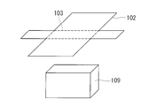
- FIG. 13 it is possible to easily bend the target object 109 to be attached at a predetermined location by sewing in advance a line to be a crease to form a stitched portion.
- the heat insulating sheet 102a and the spacer 102b are crimped at the seamed portion, resulting in deterioration of the heat insulating performance.
- the present invention has been made in view of such circumstances, and it is an object of the present invention to provide a multilayer heat insulating material which suppresses the deterioration of the heat insulating performance around the mounting means and facilitates the deformation to a desired shape. Do.
- a multilayer heat insulating material includes a heat insulating member in which a heat insulating sheet and a spacer are stacked, a locking sheet provided adjacent to the heat insulating member, the heat insulating member and the lock A heat insulating member stop which penetrates and locks the seat for the seat, and a mounting member which is provided on the stop sheet and which is attachable to and detachable from an object to be mounted; And locking the respective layers of the heat insulating member so as not to be in close contact with each other.
- the heat insulating member and the locking sheet are locked by the heat insulating member locking tool such that the heat insulating sheet and the spacer are not in close contact with each other.
- the heat insulating member and the locking sheet are detachably attached to the mounting object by the mounting member provided on the locking sheet. Since the mounting member is provided on the locking sheet, it is not directly attached to the heat insulating member. And since the heat insulating member stopper is locked so that the layers of the heat insulating member do not contact closely, it is possible to prevent the deterioration of the heat insulating performance due to the contact of the layers of the heat insulating member.
- the heat insulating member locking device is provided at a shaft portion penetrating the heat insulating member and the locking sheet in the stacking direction, and at both ends of the shaft portion And a length of the shaft portion is longer than a thickness when the heat insulating member and the locking sheet are brought into contact in a state where no load is applied. .
- the layers of the heat insulating member are not brought into close contact by making the length of the shaft portion of the heat insulating member locking tool longer than the thickness when the heat insulating member and the locking sheet are in contact with each other without load applied. Can be locked.
- the locking sheet is a mesh or porous sheet.
- the locking sheet is characterized by including a bent portion in which a bending line can be formed along a predetermined direction.
- a bending portion is provided on the locking sheet, and a bending line is formed along a predetermined direction. Thereby, a multilayer heat insulating material can be mounted according to the shape of the mounting target.
- the locking sheet includes a plurality of locking sheet pieces and a sheet connection portion that connects the locking sheet pieces, and the bending is performed.
- the part is formed by the sheet connection part.
- the locking sheet is divided into a plurality of locking sheet pieces, and a sheet connection portion for connecting the locking sheet pieces is provided.
- the sheet connection portion forms a bent portion.
- a sheet seat connection part, an adhesive tape, a resin film, etc. are mentioned, for example.
- the plurality of locking sheet pieces are characterized in that they have shapes corresponding to the respective surfaces of the mounting object.
- the multilayer heat insulating material can be mounted according to the shape of the mounting object.
- Deterioration of the heat insulating performance around the mounting means of the multilayer heat insulating material can be suppressed, and deformation to a desired shape can be facilitated.
- FIG. 2 is a cross-sectional view taken along the line A-A ′ of FIG.
- FIG. 2 is a cross-sectional view taken along the line A-A ′ of FIG.
- the manufacturing method of the multilayer heat insulating material which concerns on 1st Embodiment of this invention it is a figure which shows latching of the laminated body by insertion of a heat insulating material latching tool.
- the manufacturing method of the multilayer heat insulating material which concerns on 1st Embodiment of this invention it is a figure which shows stitching
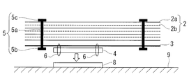
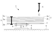
- the multilayer heat insulating material 1 according to the present embodiment is fastened to the heat insulating member 2, the locking sheet 3 provided adjacent to the heat insulating member, and the locking sheet 3, as shown in FIGS. 1 and 2.
- the mounting member 4 and the heat insulating member fastener 5 are provided.
- the heat insulating member 2 is formed by stacking 10 to 20 layers of the heat insulating sheet 2a with the spacer 2b interposed.
- An example of a thermal insulation sheet is a low emissivity film, such as a metal film deposited on a 10-20 micrometer thick resin film.
- a metal film deposited on a 10-20 micrometer thick resin film.
- a metal Al, Ag, Au, etc.
- Kapton film having a thickness of 10 to 20 micrometers can be mentioned.
- a mounting object 9 such as a rocket or a spacecraft such as an artificial satellite, or a device mounted on a spacecraft
- a mounting object 9 such as a rocket or a spacecraft such as an artificial satellite, or a device mounted on a spacecraft
- the spacer 2b a net-like member made of a heat insulating material or a porous sheet-like member can be mentioned, and in particular, one made of a material having a thermal conductivity lower than that of the film used for the heat insulating sheet 2a is preferable.
- the locking sheet 3 is fastened by the mounting member 4 and the suture thread 6.
- the mounting member 4 is used when mounting the multilayer heat insulating material 1 to the mounting object 9.
- the mounting member 8 is provided on the surface of the mounting object 9 and the mounting member 4 is mounted on the mounting member 8.
- the mounting member 4 is not fastened to the heat insulating member 2.
- the mounting member 4 is preferably a mounting means that can be repeatedly removed, and in particular it is desirable that the mounting member 4 can be removed by an operation from the outside of the multilayer heat insulating material 1.
- An example of the mounting member 4 is a hook and loop fastener, but fasteners such as snaps and hooks can also be used.
- the locking sheet 3 can be repeatedly attached to and detached from the spacecraft and devices mounted on the spacecraft.
- the locking sheet 3 has such a strength that it does not break even if it is repeatedly attached and detached.
- Preferred examples of the locking sheet 3 include styrene, polyethylene, polypropylene, polytetrafluoroethylene, and sheets obtained by processing these foams.
- Other suitable examples of the locking sheet 3 include a reticulated sheet or a porous sheet made of styrene, polyethylene, polypropylene, polytetrafluoroethylene.
- the heat insulating member fasteners 5 are dispersedly provided in the in-plane direction of the laminate including the heat insulating member 2 and the locking sheet 3.
- the heat insulating member stopper 5 includes a shaft 5 a and a pair of locking parts 5 b and 5 c provided at both ends of the shaft 5 a.
- the locking portion 5b is provided on the outside of the locking sheet 3 of the laminated body, and the locking portion 5c is provided on the outside of the heat insulating member 2 of the laminated body.
- a tag pin attached by a tag gun is raised.
- Examples of the material of the heat insulating member stopper 5 include nylon.
- the shaft 5 a is provided so as to penetrate the layers (the heat insulating sheet 2 a and the spacer 2 b stacked) and the locking sheet 3 of the heat insulating member 2.
- the heat insulating member locking tool 5 is formed such that the length of the shaft portion 5 a is equal to or more than the sum of the thickness of the heat insulating member 2 formed by laminating and the thickness of the locking sheet 3. For this reason, the interlayer distance of each layer of the heat insulating member 2 is not narrowed by the heat insulating member locking tool 5 without being greatly narrowed. Therefore, the heat insulation performance does not deteriorate due to the pressure bonding of each layer of the heat insulation member.
- the sum of the thickness of the heat insulating member 2 formed by lamination and the thickness of the locking sheet 3 is the thickness when the heat insulating member is in contact in a state where no load is applied, ie, the heat insulating member 2 It means the thickness of the state where and and the seat 3 for locking overlap by dead weight.
- the shaft portion 5a does not restrain the layers of the heat insulating member 2 and the locking sheet 3 in the stacking direction in the penetrating portion of the laminate, and the shaft portion 5a and the layers of the heat insulating member 2 and the locking sheet 3 are of the shaft portion 5a.
- the relative position can be changed in the extending direction.
- the locking portions 5b and 5c are each formed so as to have a portion longer than the diameter of the hole formed in the through portion of the laminate through which the shaft portion 5a passes in a direction intersecting the shaft portion 5a.
- the locking portions 5b and 5c are each rod-like or plate-like, and are connected to the shaft 5a at central portions in the respective longitudinal directions, and are longer than the diameter of the hole in the direction intersecting the shaft 5a from the connecting portion To extend. This prevents the heat insulating member stopper 5 from falling out of the laminate.
- the locking portions 5b and 5c are each formed of a material and in a shape such that the locked state can be maintained even when a force is applied to the heat insulating member locking tool 5 when the multilayer heat insulating material 1 is attached and detached.
- the heat insulating member fasteners 5 are dispersedly provided in the surface direction of the laminate. For example, as shown in FIG. 1, they are provided dispersedly at the four corners of the laminate.
- each layer of the heat insulating member 2 It is possible to suppress the decrease in heat insulation performance due to the pressure bonding of
- a spacer 2 b is interposed between the heat insulating sheet 2 a and the heat insulating sheet 2 a, and a predetermined number of sheets are stacked to form the heat insulating member 2.
- the heat insulating sheet 2a is formed, for example, by forming a film in which metal is vapor-deposited on a resin film such as Kapton, in a predetermined shape.
- the locking sheet 3 is placed adjacent to the heat insulating member 2 to form a laminate.
- the heat insulating member 2 is placed on the locking sheet 3 so that the lower surface of the heat insulating member 2 and the upper surface of the locking sheet 3 are adjacent to each other.
- the mounting member 4 is fastened to the locking sheet 3 by sewing or the like.
- the mounting member 4 is fastened to the opposite side of the surface where the locking sheet 3 is adjacent to the heat insulating member 2.
- the heat insulating member stopper 5 is inserted from the upper surface of the heat insulating member 2 of the laminate so as to penetrate the layers of the heat insulating member 2 and the locking sheet 3.
- a tag pin is used as the heat insulating member stopper 5, and the tag pin is inserted from the upper surface of the heat insulating member 2 using a tag gun.
- insertion may be made while forming a through hole in the heat insulating member 2 and the locking sheet 3, or in the case where a hole is formed in advance in at least a part of the heat insulating member 2 and the locking sheet 3. May be inserted through the holes and through them.
- the inserted heat insulating member locking tool 5 penetrates the heat insulating member 2 and the locking sheet 3 and then, below the locking sheet 3, the locking portion 5b is centered on the connecting portion with the shaft portion 5a, It deforms into a shape extending longer than the diameter of the hole in the direction intersecting the shaft 5a from the connection.
- the heat insulating member 2 and the locking sheet 3 are locked so that the heat insulating member locking tool 5 does not fall out of the laminated body.
- the locking portion 5b is folded so as to be substantially parallel to the shaft portion 5a.
- the heat insulating member 2 is fixed by being inserted into the heat insulating member 2 and the locking sheet 3 so as to penetrate, and then the fixed state is released below the locking sheet 3.
- the shape may be recovered by elasticity, and the heat insulating member 2 and the locking sheet 3 may be locked.
- each layer of the laminated body can slide on the shaft portion 5a and can be easily deformed into a desired shape.
- Steps 1-3 and 1-4 described above are repeated, and the heat insulating member 2 is locked to the locking sheet 3 by providing a predetermined number of the heat insulating member fasteners 5 in a distributed manner in the surface direction of the laminate. And integrate the multi-layered heat insulating material 1.
- the heat insulating member 2 has a polygonal shape in plan view
- one or more heat insulating member fasteners 5 may be dispersedly provided in the vicinity of each vertex, or the sides of the polygon may be provided. It may be provided in the peripheral part in a distributed manner along a part or all of.
- the integrated multi-layered heat insulating material 1 is mounted on the mounting object 9 through the mounting member 4 fastened to the locking sheet 3 and the mounting member 8.
- the mounting member 4 and the mounting member 8 appropriately select the position and the number according to the shape of the mounting object 9.
- the mounting object is a rocket tank
- the pairs of mounting members 4 and mounting members 8 are formed in consideration of the required shape of the multilayer heat insulating material 1 and the direction of stress applied during flight. It should be arranged.
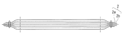
- Step 1-1 As shown in FIG. 4, after the heat insulating sheet 2a and the spacer 2b are stacked to form the heat insulating member 2, the step of sewing and integrating the peripheral portion is further provided. Good (step 1-1 '). Thereby, the handleability at the time of manufacturing the multilayer heat insulating material 1 can be improved. In this step, it is preferable that the heat insulating member 2 be formed larger than the locking sheet 3 and the peripheral edge to be sewn be extended outward from the locking sheet 3 in the surface direction.
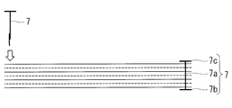
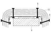
- the some heat insulation member peripheral part is formed in the peripheral part. It may further comprise the step of providing the fasteners 7 in a distributed manner and integrating them (step 1-1 ′ ′).
- the heat insulating member peripheral edge locking tool 7 is provided through the heat insulating member 2 and has a heat insulating member peripheral edge locking tool shaft 7 a having a length equal to or greater than the thickness of the heat insulating member 2 formed by stacking.
- the heat insulating member peripheral edge fastener 7 is inserted from the upper surface of the heat insulating member 2 so as to penetrate each layer of the heat insulating member 2, and the heat insulating member peripheral edge fastener is engaged below the heat insulating member 2.
- a shape in which the stop portion 7b extends longer than the diameter of the hole in the direction in which the stop portion 7b intersects the heat insulating member peripheral locking portion shaft portion 7a from the connecting portion centering on the connection portion with the heat insulating member peripheral portion locking shaft portion 7a Transform into This is repeated, and the heat insulating member 2 is integrated by dispersing and providing a predetermined number of heat insulating member peripheral edge fasteners 7 in the surface direction of the heat insulating member 2.
- the length of the heat insulating member peripheral portion engaging tool shaft 7a is longer than the thickness of the heat insulating member 2 formed by laminating, even if the heat insulating member 2 is integrated by the heat insulating member peripheral edge engaging member 7, the heat insulating member There is no need to greatly reduce the distance between the two layers. Thereby, the handleability can be improved without deteriorating the heat insulating performance due to the close contact of the layers of the heat insulating member 2.
- the heat insulation member peripheral part latching tool 7 you may make it insert in the heat insulation member 2 by the same means as the heat insulation member fastener 5 using the same thing as the above-mentioned heat insulation member fastener 5.
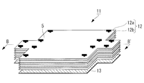
- the multilayer heat insulating material 11 which concerns on this embodiment is shown in FIG. 6 thru
- the multilayer heat insulating material 11 according to the present embodiment is fastened to the heat insulating member 12, the locking sheet 13 provided adjacent to the heat insulating member 12, and the locking sheet 13, as shown in FIGS. Mounting member 4 and the heat insulating member fastener 5.
- the laminated body consisting of the heat insulating member 12 and the locking sheet 13 is integrated by the heat insulating member locking tool 5.
- the locking sheet 13 includes a plurality of locking sheet pieces 13a and a flexible sheet connecting portion (bending portion) 13b that connects the plurality of locking sheet pieces.
- the locking sheet 13 has at least a part of a surface constituting a developed view in which a predetermined three-dimensional shape 13 ′ surrounding the mounting object 9 is developed. That is, each locking sheet piece 13 a has a shape corresponding to each surface of the mounting object 9. Specifically, it has a shape that can form a predetermined three-dimensional shape 13 ′ surrounding the mounting object 9 by bending the locking sheet 13 at the sheet connection portion 13 b.
- the locking sheet 13 shown in FIG. 11 does not have a portion corresponding to the bottom surface and is shaped to cover the mounting object 9 from above, it is also configured to have the bottom surface and cover the entire mounting object 9 Good.
- the locking sheet piece 13a is made of, for example, styrene, polyolefin, polypropylene, polytetrafluoroethylene or the like, and is a sheet piece on a flat plate having rigidity.
- the multi-layered heat insulating material 11 is deformed along the shape of the mounting object 9, the shape of the locking sheet 13 is maintained, and the locking portions 5b and 5c of the heat insulating member locking tool 5 are not broken. It is desirable to determine the thickness and material so that it can be locked.
- Each of the locking sheet pieces 13a has at least one shape of surfaces constituting a developed view in which a predetermined three-dimensional shape 13 'surrounding the mounting object 9 is developed. The thickness and material of the locking sheet 13 may be locally changed.
- the sheet connection portion 13b is a flexible material that connects the peripheral edge portion and the peripheral edge portion of the locking sheet piece 13a, and connects the locking sheet piece 13a so that the relative position can be deformed.
- the sheet connection portion 13 b is formed more flexibly than the locking sheet piece 13 a having rigidity. Thereby, when making the multilayer heat insulating material 11 deform
- the sheet connecting portion 13 b preferably has a structure in which the sheet connecting portion 13 b is bonded to the inside in the bending direction of the locking sheet 13.
- the heat insulating member 12 is formed by overlapping 10 to 20 layers of the heat insulating sheet 12 a with the spacer 12 b interposed therebetween.
- the heat insulating member 12 is larger than the locking sheet 13 in plan view, and has a shape that covers the entire locking sheet in a state where the locking sheet 13 is bent inward.
- the peripheral shape of the locking sheet 13 is substantially the same as the locking sheet 13 and extends outward from the locking sheet in the surface direction.
- the multi-layered heat insulating material 11 is bent at the sheet connection portion 13 b and deformed along the shape of the mounting object 9, no gap is generated and the pressure bonding of each layer of the heat insulating member 12 is performed.
- the object to be mounted can be covered with the heat insulating member 12 without causing the deterioration of the heat insulating performance due to the above.
- the peripheral portions of the heat insulating member 12 may be in abutment or may be in an overlapping state.
- the heat insulating member fasteners 5 are dispersedly provided in the in-plane direction of the laminate including the heat insulating member 12 and the locking sheet 13.
- the shaft portion 5 a of the heat insulating member locking tool 5 is provided so as to penetrate through the layers (the stacked heat insulating sheet 12 a and the spacer 12 b) of the heat insulating member 12 and the locking sheet 13.
- the heat insulating member locking tool 5 is formed such that the length of the shaft portion 5 a is equal to or more than the sum of the thickness of the heat insulating member 12 formed by stacking and the thickness of the locking sheet 13.
- the interlayer distance of each layer of the heat insulating member 2 is not greatly narrowed by the heat insulating member fastener 5, and hence the heat insulating performance is not deteriorated due to the pressure bonding of each layer of the heat insulating member.
- the sum of the thickness of the heat insulating member 12 formed by laminating and the thickness of the locking sheet 13 is the thickness when the heat insulating member is in contact with no load applied, ie, the heat insulating member 12 It means the thickness of the state where and and the seat 13 for locking overlap by dead weight.
- the length of the shaft 5a may be locally changed beforehand in advance.
- the shaft portion 5a does not restrain the layers of the heat insulating member 12 and the locking sheet 13 in the stacking direction in the penetrating portion of the laminate, and the shaft portion 5a and the layers of the heat insulating member 12 and the locking sheet 13 are of the shaft portion 5a.
- the relative position can be changed in the extending direction.
- the locking portions 5b and 5c are each formed so as to have a portion longer than the diameter of the hole formed in the through portion of the laminate through which the shaft portion 5a passes in a direction intersecting the shaft portion 5a. There is.
- the locking portions 5b and 5c are each rod-like or plate-like, and are connected to the shaft 5a at central portions in the respective longitudinal directions, and are longer than the diameter of the hole in the direction intersecting the shaft 5a from the connecting portion To extend.
- the locking portions 5b and 5c are each formed of a material and in a shape such that the locked state can be maintained even when a force is applied to the heat insulating member locking tool 5 when the multilayer heat insulating material 11 is attached and detached.
- the heat insulating member fasteners 5 be dispersedly provided in the surface direction so as to penetrate the peripheral portion of the fastening sheet piece 13a.
- the position where the heat insulating member locking tool 5 is provided is determined on the assumption that the locking sheet 13 is bent at the sheet connecting portion 13 b to form a predetermined three-dimensional shape 13 ′ surrounding the object 9 to be mounted.
- the heat insulating member fasteners 5 are provided at the four corners of the locking sheet piece 13 a corresponding to the top plate of the three-dimensional shape 13 ′.
- the locking sheet piece 13a corresponding to the top plate of the three-dimensional shape 13 ' is located at the center of bending the locking sheet 13 at the sheet connection portion 13b, and the positional variation at the time of bending is small.
- the variation in the relative position between each layer of the heat insulating member 12 and the locking sheet 13 is a small part. Therefore, the heat insulating member is efficiently fixed by fixing the relative position with the locking sheet 13 by first providing the heat insulating member locking tool 5 at the four corners of the locking sheet piece 13a corresponding to the top plate of the three-dimensional shape 13 '. 12 can be locked to the locking sheet 13.
- the heat insulating member fasteners 5 are also provided on the peripheral portions (peripheral portions on the opposite side of the sheet connection portion 13b) of the respective locking sheet pieces 13a connected at the peripheral portions.
- the multilayer heat insulating material can be integrated regardless of the change of the relative position at the time of bending.
- each locking sheet piece 13a is formed into a shape as shown in FIG. 11 based on the shape of each surface constituting this developed view.
- the locking sheet piece 13a maintains the shape and is not broken It selects so that the latching
- the peripheral edge portions of the respective locking sheet pieces 13a are connected by the sheet connecting portion 13b so as to form a developed view (see FIG. 7), and the locking sheet 13 is formed.
- the locking sheet 13 is adhered to the peripheral portion of the locking sheet piece 13a from the inner side when the locking sheet 13 is bent.
- the mounting member 4 is fastened to the locking sheet 13 by sewing or the like.
- the mounting member 4 is fastened to the locking sheet piece 13a positioned at the center when the locking sheet 13 is folded.
- the plurality of attachment members 4 may be attached to the plurality of locking sheet pieces 13 a for attachment of the multilayer heat insulating material.
- a predetermined number of sheets are laminated by interposing the spacer 12b between the heat insulating sheet 12a and the heat insulating sheet 12a.
- the heat insulation member 12 is formed.
- the heat insulating sheet 12a is formed by, for example, forming a film in which metal is vapor-deposited on a resin film such as Kapton, in a predetermined shape.
- the shape of the heat insulating sheet 12 a is substantially the same as the shape of the locking sheet 13, and the peripheral edge portion of the heat insulating sheet 12 a extends outward in the plane direction from the locking sheet.
- the locking sheet 13 is placed adjacent to the heat insulating member 12 to form a laminate.
- the heat insulating member 12 is placed on the locking sheet 13 so that the lower surface of the heat insulating member 12 and the upper surface of the locking sheet 13 are adjacent to each other.
- the mounting member 4 is disposed on the opposite side of the surface where the locking sheet 13 is adjacent to the heat insulating member 12.
- each layer of the heat insulating member 12 and the locking sheet 13 from the upper surface of the heat insulating member 12 of the laminate are inserted so as to penetrate the
- a tag pin is used as the heat insulating member stopper 5, and the tag pin is inserted from the upper surface of the heat insulating member 12 using a tag gun.
- insertion may be made while forming a through hole in the heat insulating member 12 and the locking sheet 13, or in the case where a hole is formed in advance in at least a part of the heat insulating member 12 and the locking sheet 13. May be inserted through the holes and through them.
- the inserted heat insulating member locking tool 5 penetrates the heat insulating member 12 and the locking sheet 13 and then, below the locking sheet 13, the locking portion 5b is centered on the connecting portion with the shaft portion 5a, It deforms into a shape extending longer than the diameter of the hole in the direction intersecting the shaft 5a from the connection. As a result, the heat insulating member locking tool 5 is locked from the laminated body so that the heat insulating member 12 and the locking sheet 13 are locked.
- the shaft portion 5a By forming the shaft portion 5a to have a smooth surface shape in the extension direction of the shaft portion, each layer of the laminated body can slide on the shaft portion 5a and can be easily deformed into a desired shape. (Step 2-5)
- Steps 2-4 and 2-5 are repeated, and the heat insulating member 12 is locked to the locking sheet 13 by dispersing the predetermined number of heat insulating member fasteners 5 in the surface direction of the laminate.
- the multi-layered heat insulating material 11 is integrated.
- the heat insulating member stoppers 5 are provided at the four corners of the locking sheet piece 13a corresponding to the top plate of the three-dimensional shape 13 ', and further, the peripheral portions of the respective locking sheet pieces 13a connected by the peripheral portion
- the heat insulating member stopper 5 is also provided on the (peripheral portion on the opposite side to the sheet connection portion 13b).
- the heat insulating member stopper 5 is provided, assuming that the outer layer of the heat insulating member 12 has a larger radius of curvature than the inner layer when the locking sheet 13 is bent in a shape convex outward at the inner side. Decide.
- the heat insulating member fasteners 5 are provided in the substantially vertical direction (stacking direction) at the four corners of the fastening sheet piece 13a corresponding to the top plate of the three-dimensional shape 13 ′.
- the heat insulating member stopper 5 ′ having the longer shaft portion 5 a ′ is disposed in the stacking direction so as to penetrate the position (a spaced position) advanced from the bending planned position toward the outer layer. It is installed diagonally.
- heat insulation member fastener 5 ' is extended in the part extended from a bending plan position. It may be provided substantially vertically.
- the integrated multi-layered heat insulating material 11 is mounted on the mounting object 9 by connecting the mounting member 4 fastened to the locking sheet 13 and the mounting member 8 on the other side. At the time of mounting, the multi-layer heat insulating material 11 is deformed according to the shape of the mounting object 9 by bending the locking sheet 13 so as to form a predetermined three-dimensional shape 13 ′. The mounting member 4 and the mounting member 8 appropriately select the position and the number according to the shape of the mounting object 9.
- the peripheral portions are sewn together It may further comprise the step of integrating (step 2-2 ').
- the step of integrating it is preferable that the heat insulating member 12 be formed larger than the locking sheet 13 and the peripheral edge to be sewn be extended outward from the locking sheet 13 in the surface direction.
- the portion extending from the locking sheet may be cut out together with the sewn portion. In this case, the contact state of each layer of the heat insulating member caused by the sewed peripheral portion is alleviated.
- the heat insulating member peripheral portion fastener 7 may be provided in a distributed manner and integrated (step 2-2 ′ ′).
- the heat insulating member peripheral edge locking member 7 is inserted from the upper surface of the heat insulating member 12 so as to penetrate each layer of the heat insulating member 12, and the heat insulating member peripheral edge locking member locking portion 7 b is below the heat insulating member 2.
- the heat insulating member 2 is integrated by dispersing and providing a predetermined number of heat insulating member peripheral edge fasteners 7 in the surface direction of the heat insulating member 2.
- the heat insulating member peripheral edge engaging member 7 the same one as the above-described heat insulating member engaging member 5 may be used, and the heat insulating member engaging member 5 may be inserted into the heat insulating member 12 by the same means.
- the locking sheet 13 is not divided, You may make a line which becomes a crease by a cut and a hollow.
Landscapes
- Engineering & Computer Science (AREA)
- Mechanical Engineering (AREA)
- Physics & Mathematics (AREA)
- Thermal Sciences (AREA)
- Health & Medical Sciences (AREA)
- Critical Care (AREA)
- Emergency Medicine (AREA)
- General Health & Medical Sciences (AREA)
- Remote Sensing (AREA)
- Aviation & Aerospace Engineering (AREA)
- General Engineering & Computer Science (AREA)
- Thermal Insulation (AREA)
Abstract
装着対象物への装着手段の周辺での断熱性能の悪化を抑え、所望の形への変形を容易にする多層断熱材を提供する。断熱シート(2a)とスペーサ(2b)とが積層された断熱部材(2)と、断熱部材(2)に隣接して設けられた係止用シート(3)と、断熱部材(2)と係止用シート(3)とを貫通して係止する断熱部材係止具(5)と、係止用シート(3)に設けられ、装着対象物(9)に対して着脱可能とされた装着部材(4)とを備え、断熱部材係止具(5)は、断熱部材(2)の各層が密着しないように係止する。
Description
本発明は、宇宙空間を航行する宇宙機又はその搭載機器等に使用する多層断熱材に関するものである。
宇宙空間を航行する宇宙機、特にロケット、人工衛星やその搭載機器において、温度管理は重要な要素となる。宇宙空間にある宇宙機は、真空中で太陽光に曝露されるため、太陽光からの輻射により曝露部分の温度が高温化する。一方、太陽光のあたらない部分は輻射により放熱して低温となる。このため、ロケット、人工衛星の稼動期間にわたって搭載機器周辺の温度が適正な作動温度域となるように、入熱を抑制すると共に搭載機器周辺の温度を維持する対策が必要となる。
このような対策の一つとして、「サーマルブランケット」とも呼ばれる多層断熱材を適用することが知られている。
多層断熱材は、放射率の低い断熱シートを重ねて形成される。このような多層断熱材では、断熱シートの層間にスペーサを介挿することで、断熱シート相互の接触による熱伝導を防ぎ、断熱効果を高めている。
このような多層断熱材で宇宙機又は宇宙機搭載機器を覆うことで、宇宙機外部からの輻射による入熱を抑制すると共に、宇宙機内部からの輻射による放熱を抑制する。これにより宇宙機の温度環境を適正な作動温度域に維持することができる。
多層断熱材は、放射率の低い断熱シートを重ねて形成される。このような多層断熱材では、断熱シートの層間にスペーサを介挿することで、断熱シート相互の接触による熱伝導を防ぎ、断熱効果を高めている。
このような多層断熱材で宇宙機又は宇宙機搭載機器を覆うことで、宇宙機外部からの輻射による入熱を抑制すると共に、宇宙機内部からの輻射による放熱を抑制する。これにより宇宙機の温度環境を適正な作動温度域に維持することができる。
このような多層断熱材は宇宙機や宇宙機搭載機器の周辺を覆うように宇宙機本体に装着されるが、宇宙機の調整作業のために艤装した多層断熱材の着脱や位置の調整を繰り返し行うことを要する場合がある。多層断熱材に着脱可能な装着手段を採用することで、このような作業を効率的に行うことができる。例えば、図12に示すように、多層断熱材(サーマルブランケット)102を、面ファスナ104などを用いて取付面へ装着する方法が知られている。
下記の特許文献1では、サーマルブランケットを、面ファスナ(ベルクロ(登録商標)テープ)を用いて取付面へ装着する方法が開示されている。
下記の特許文献1では、サーマルブランケットを、面ファスナ(ベルクロ(登録商標)テープ)を用いて取付面へ装着する方法が開示されている。
多層断熱材は、断熱シート同士が圧着してしまうと、その部分で熱伝導による熱リークが発生し、断熱性能を悪化させる要因となる。このような圧着箇所は、多層断熱材の装着手段の周辺において生じやすい。図12に示すように、従来の面ファスナ104を装着手段として用いた場合には、多層断熱材102を面ファスナ104に縫合糸103によって縫い付けるため、面ファスナ104の周辺で断熱シート102aとスペーサ102bの圧着が生じてしまう。
一方で、多層断熱材102は断熱シート102a間にスペーサ102bを介挿して積層されて形成されるため、そのままではばらばらになるなど取り扱いにくい。これを取り扱い容易とするため縫製により一体化すると、所望の形状へ変形させにくくなる。例えば宇宙機搭載機器を覆う際に、その立体形状に沿うように、所定箇所で変形させることが容易ではないことがある。これに対し、図13に示すように、予め、折り目となる線を縫い合わせて縫合部としておくことで、取付対象となる対象物109の所定箇所での折り曲げを容易とすることができるが、この場合は縫合部において断熱シート102aとスペーサ102bの圧着を生じ、断熱性能の悪化を生じてしまう。
本発明は、このような事情に鑑みてなされたものであって、装着手段の周辺の断熱性能の悪化を抑え、所望の形への変形を容易にする多層断熱材を提供することを目的とする。
本発明は、上記課題を解決するため、以下の手段を採用している。
即ち、本発明の一態様に係る多層断熱材は、断熱シートとスペーサとが積層された断熱部材と、前記断熱部材に隣接して設けられた係止用シートと、前記断熱部材と前記係止用シートとを貫通して係止する断熱部材係止具と、前記係止用シートに設けられ、装着対象物に対して着脱可能とされた装着部材とを備え、前記断熱部材係止具は、前記断熱部材の各層が密着しないように係止することを特徴とする。
即ち、本発明の一態様に係る多層断熱材は、断熱シートとスペーサとが積層された断熱部材と、前記断熱部材に隣接して設けられた係止用シートと、前記断熱部材と前記係止用シートとを貫通して係止する断熱部材係止具と、前記係止用シートに設けられ、装着対象物に対して着脱可能とされた装着部材とを備え、前記断熱部材係止具は、前記断熱部材の各層が密着しないように係止することを特徴とする。
断熱部材と係止用シートとは、断熱部材係止具によって断熱シートとスペーサとが密着しないように係止される。係止用シートに設けられた装着部材によって、断熱部材及び係止用シートが装着対象物に対して着脱可能に取り付けられる。装着部材は、係止用シートに設けられているので、断熱部材に直接取り付けられていない。そして、断熱部材係止具は、断熱部材の各層が密着しないように係止しているので、断熱部材の各層の密着による断熱性能の悪化を生ずること回避することができる。
さらに、本発明の一態様に係る多層断熱材では、前記断熱部材係止具は、前記断熱部材と前記係止用シートとを積層方向に貫通する軸部と、前記軸部の両端に設けられた一対の係止部とを備え、前記軸部の長さは、前記断熱部材及び前記係止用シートの積層方向に荷重が加わらない状態で接触したときの厚さよりも長いことを特徴とする。
断熱部材係止具の軸部の長さを、断熱部材及び係止用シートの積層方向に荷重が加わらない状態で接触したときの厚さよりも長くすることで、断熱部材の各層を密着させないように係止することができる。
さらに、本発明の一態様に係る多層断熱材では、前記係止用シートは、網状又は多孔状のシートであることを特徴とする。
係止用シートとしては、網状又は多孔状のシートとすることで、熱伝導を抑制しつつ、重量増加を抑えることができる。
さらに、本発明の一態様に係る多層断熱材では、前記係止用シートは、所定方向に沿って折り曲げ線が形成可能な折り曲げ部を備えていることを特徴とする。
係止用シートに折曲げ部を設け、所定方向に沿って折り曲げ線が形成されるようにした。これにより、装着対象物の形状に応じて多層断熱材を装着することができる。
さらに、本発明の一態様に係る多層断熱材では、前記係止用シートは、複数の係止用シート片と、各前記係止用シート片どうしを接続するシート接続部とを備え、前記折り曲げ部は、前記シート接続部によって形成されていることを特徴とする。
係止用シートを複数の係止用シート片に分割し、各係止用シート片を接続するシート接続部を設けることとした。このシート接続部によって折り曲げ部が形成される。シート接続部としては、例えば、粘着テープや樹脂フィルムなどが挙げられる。
さらに、本発明の一態様に係る多層断熱材では、複数の前記係止用シート片は、装着対象物の各面に対応した形状とされていることを特徴とする。
各係止用シート片を、装着対象物の各面に対応した形状とすることで、装着対象物の形状に合わせて多層断熱材を装着することができる。
多層断熱材の装着手段の周辺の断熱性能の悪化を抑え、所望の形への変形を容易にすることができる。
[第1実施形態]
以下、本発明の第1実施形態に係る多層断熱材について、図面を用いて説明する。
以下、本発明の第1実施形態に係る多層断熱材について、図面を用いて説明する。
本実施形態に係る多層断熱材1は、図1および図2に示すように、断熱部材2と、断熱部材に隣接して設けられる係止用シート3と、係止用シート3に締結される装着部材4と、断熱部材係止具5とを備える。
断熱部材2は、断熱シート2aを、スペーサ2bを介挿して10~20層重ねて形成される。断熱シートの例としては、放射率の低いフィルム、例えば、厚さ10~20マイクロメートルの樹脂フィルム上に金属を蒸着させたものが挙げられる。好適な例としては、厚さ10~20マイクロメートルのカプトンフィルム上に金属(Al、Ag、Auなど)を蒸着したものが挙げられる。金属を蒸着させることで光や電磁波の反射率が向上するので、多層断熱材として装着対象物9(ロケット、人工衛星などの宇宙機や宇宙機に搭載される機器など)に装着した際に、外部からの輻射による入熱を抑制すると共に、内部からの輻射による外部への放熱を抑制する。スペーサ2bの例としては、断熱材でつくられた網状部材あるいは多孔性のシート状部材が挙げられ、特に断熱シート2aに用いられるフィルムよりも熱伝導率が低い材質でつくられたものが好ましい。
係止用シート3は装着部材4と縫合糸6によって締結される。装着部材4は、多層断熱材1を装着対象物9に装着する際に使用される。例えば、装着対象物9の表面に対となる装着部材8を設け、装着部材4を装着部材8に対して装着する。装着部材4は、断熱部材2とは締結されない。装着部材4は繰り返し着脱可能な装着手段であることが望ましく、特に多層断熱材1の外側からの操作で着脱できることが望ましい。装着部材4の例としては面ファスナが挙げられるが、スナップやフックなどの締結具を用いることもできる。装着部材4により、係止用シート3を、宇宙機や宇宙機に搭載される機器へ繰り返し着脱可能となっている。係止用シート3は、着脱を繰り返しても壊れない程度の強度を持つ。係止用シート3の好適な例としては、スチレン、ポリエチレン、ポリプロピレン、ポリテトラフルオロエチレンあるいはこれらの発泡体をシート状に加工したものが挙げられる。係止用シート3の好適な別の例としては、スチレン、ポリエチレン、ポリプロピレン、ポリテトラフルオロエチレンでつくられた網状シートあるいは多孔シートが挙げられる。
断熱部材係止具5は、断熱部材2と係止用シート3とからなる積層体の面内方向に分散して設けられる。断熱部材係止具5は、軸部5aと、軸部5aの両端に設けられる一対の係止部5b、5cを備える。係止部5bは積層体の係止用シート3の外側に設けられ、係止部5cは積層体の断熱部材2の外側に設けられる。断熱部材係止具5としては、例えばタグガンで取り付けられるタグピンが上げられる。断熱部材係止具5の材質としては、例えばナイロンが挙げられる。
軸部5aは、断熱部材2の各層(積層された断熱シート2aおよびスペーサ2b)および係止用シート3を貫通して設けられる。断熱部材係止具5は、軸部5aの長さが、積層して形成された断熱部材2の厚さと係止用シート3の厚さの和以上となるように形成されている。このため、断熱部材2の各層の層間距離は断熱部材係止具5によって大きく狭められることなく密着することがない。従って断熱部材の各層の圧着による断熱性能の悪化を生ずることがない。なお、積層して形成された断熱部材2の厚さと係止用シート3の厚さの和としては、断熱部材の積層方向に荷重が加わらない状態で接触したときの厚さ、すなわち断熱部材2と係止用シート3とが自重によって重なった状態の厚さを意味する。
軸部5aは、積層体の貫通部分において断熱部材2の各層および係止用シート3を積層方向に拘束せず、軸部5aと断熱部材2の各層および係止用シート3は軸部5aの延在方向に相対位置を変えることができる。
係止部5b、5cは、それぞれが、軸部5aが貫通している積層体の貫通部分に形成された孔の径より長い部分を、軸部5aと交差する方向に有するように形成されている。例えば、係止部5b、5cはそれぞれが棒状もしくは板状であり、それぞれの長手方向の央部で軸部5aと接続し、接続部から軸部5aと交差する方向に、孔の径より長く延在する。これにより積層体から断熱部材係止具5が抜け落ちることを防ぐ。係止部5b、5cは、それぞれが、多層断熱材1の着脱の際に断熱部材係止具5に力が加わっても係止状態を維持できるような材質と形状に形成される。
断熱部材係止具5は、積層体の面方向に分散して設けられる。例えば、図1に示したように積層体の四隅に分散して設けられる。
このように、断熱部材係止具5により断熱部材2が係止用シート3に係止され、係止用シート3が装着部材4により装着対象物9に装着されるので、断熱部材2の各層の圧着による断熱性能低下を抑制することができる。
次に、本実施形態に係る多層断熱材の製造方法について説明する。
まず、図3に示すように、断熱シート2aと、断熱シート2aの間にスペーサ2bを介挿して所定の枚数を積層し、断熱部材2を形成する。断熱シート2aは、例えばカプトンなどの樹脂フィルムに金属を蒸着したフィルムを、所定形状に成形して形成する。(ステップ1-1)
次に、図3に示すように、断熱部材2に隣接するように、係止用シート3を設置し、積層体を形成する。例えば、断熱部材2を係止用シート3の上に載置し、断熱部材2の下側表面と係止用シート3の上面を隣接させる。係止用シート3には、装着部材4を縫い合わせるなどして締結する。装着部材4は、係止用シート3が断熱部材2と隣接する面の反対側に締結される。(ステップ1-2)
次に、図3に示すように、積層体の断熱部材2の上側表面から、断熱部材2の各層と係止用シート3とを貫通するように断熱部材係止具5を挿入する。例えば、断熱部材係止具5としてタグピンを用い、断熱部材2の上側表面からタグガンを用いてタグピンを挿入する。この際、断熱部材2と係止用シート3へ貫通孔を形成しながら挿入するようにしてもよく、あるいは断熱部材2と係止用シート3の少なくとも一部へ予め穴が形成されている場合は、この孔を通ってこれらを貫通するように挿入してもよい。(ステップ1-3)
挿入された断熱部材係止具5は断熱部材2と係止用シート3とを貫通した後、係止用シート3の下方で、係止部5bが軸部5aとの接続部を中心に、接続部から軸部5aと交差する方向に、孔の径より長く延在する形状に変形する。これにより、積層体から断熱部材係止具5が抜け落ちないようにして、断熱部材2と係止用シート3とを係止する。例えば、弾性を有する材料で形成され、軸部5aと交差する係止部5bを持つ断熱部材係止具5を用いる場合は、軸部5aと略平行となるように係止部5bを畳んだ状態に固定して、断熱部材2と係止用シート3とを貫通するように挿入し、貫通した後に係止用シート3の下方で固定状態を開放することで、断熱部材係止具5の弾性により形状を回復させ、断熱部材2と係止用シート3とを係止するようにしてもよい。また、軸部5aを軸部の延在方向に滑らかな表面形状に形成することで、積層体の各層が軸部5aをすべって移動でき、所望の形状に変形させやすくできる。(ステップ1-4)
上記のステップ1-3およびステップ1-4を繰り返し、所定個数の断熱部材係止具5を、積層体の面方向に分散して設けることで、断熱部材2を係止用シート3へ係止し、多層断熱材1を一体化する。例えば断熱部材2が平面視で多角形の形状を持つ場合は、その各頂点の近傍それぞれに1つ以上の断熱部材係止具5を分散して設けるようにしてもよく、あるいは多角形の辺の一部または全部に沿って周縁部に分散して設けるようにしてもよい。
そして、図2に示すように、一体化した多層断熱材1は、係止用シート3に締結された装着部材4と、装着部材8を介して、装着対象物9に装着される。なお装着部材4と装着部材8は、装着対象物9の形状に合わせて位置及び個数を適宜選択する。例えば装着対象物をロケット用タンクとする場合は、必要となる多層断熱材1の形状と、飛行中にかかる応力の方向とを考慮して、複数の装着部材4と装着部材8との対を配置すればよい。
なお、上述のステップ1-1において、図4に示すように、断熱シート2aとスペーサ2bを積層して断熱部材2を形成した後、その周縁部を縫い合わせて一体化するステップをさらに備えてもよい(ステップ1-1’)。これにより、多層断熱材1を製造する際の取り扱い性を向上させることができる。このステップにおいて、断熱部材2を係止用シート3より大きく形成し、縫い合わせる周縁部を、面方向で係止用シート3より外側に延在させることが好適である。この場合、断熱部材2において係止用シート3に接する部分には縫い合わせた箇所がなく、断熱部材の各層の接触による断熱性能の悪化を局所的に限ることができる。あるいは、艤装の完了後に、係止用シートから延在する部分を、縫い合わせた箇所ごと切り取ることとしてもよい。この場合、縫い合わせた周縁部により生じていた断熱部材の各層の接触状態が緩和される。
なお、上述のステップ1-1の別の変形例として、図5に示すように、断熱シート2aとスペーサ2bを積層して断熱部材2を形成した後、その周縁部に複数の断熱部材周縁部係止具7を分散して設け、一体化するステップをさらに備えてもよい(ステップ1-1’’)。断熱部材周縁部係止具7は、断熱部材2を貫通して設けられ、積層して形成された断熱部材2の厚さ以上の長さを持つ断熱部材周縁部係止具軸部7aと、断熱部材周縁部係止具軸部7aの両端に設けられる一対の断熱部材周縁部係止具係止部7b、7cとを備えるように形成する。具体的には、断熱部材2の上側表面から、断熱部材2の各層を貫通するように断熱部材周縁部係止具7を挿入し、断熱部材2の下方で、断熱部材周縁部係止具係止部7bが断熱部材周縁部係止具軸部7aとの接続部を中心に、接続部から断熱部材周縁部係止具軸部7aと交差する方向に、孔の径より長く延在する形状に変形させる。これを繰り返し、所定個数の断熱部材周縁部係止具7を、断熱部材2の面方向に分散して設けることで、断熱部材2を一体化する。断熱部材周縁部係止具軸部7aの長さが積層して形成された断熱部材2の厚さより長いことから、断熱部材周縁部係止具7によって断熱部材2を一体化しても、断熱部材2の層間距離を大きく狭めることがない。これにより、断熱部材2の各層の密着による断熱性能を悪化させることなく、取り扱い性を向上させることができる。なお断熱部材周縁部係止具7として、前述の断熱部材係止具5と同じものを用い、断熱部材係止具5と同じ手段で断熱部材2へ挿入するようにしてもよい。
[第2実施形態]
以下、本発明の第2実施形態に係る多層断熱材について、図面を用いて説明する。
以下、本発明の第2実施形態に係る多層断熱材について、図面を用いて説明する。
本実施形態に係る多層断熱材11を図6乃至図11に示す。なお、図6乃至図11において、図1あるいは図2と同一の構成部分については、図1あるいは図2と同一の符号を付して、その説明を省略する。
本実施形態に係る多層断熱材11は、図6および図7に示すように、断熱部材12と、断熱部材12に隣接して設けられる係止用シート13と、係止用シート13に締結される装着部材4と、断熱部材係止具5とを備える。断熱部材12と係止用シート13からなる積層体は、断熱部材係止具5により一体化している。
係止用シート13は、複数の係止用シート片13aと、複数の係止用シート片同士をつなぐ可撓性のシート接続部(折り曲げ部)13bとからなる。図11に示すように、係止用シート13は、装着対象物9を囲う所定の立体形状13’を展開した展開図を構成する面の、少なくとも一部の形状を有する。即ち、各係止用シート片13aは、装着対象物9の各面に対応する形状とされている。具体的には、係止用シート13を、シート接続部13bで折り曲げることで、装着対象物9を囲う所定の立体形状13’を形成できるような形状を持つ。なお図11に示す係止用シート13では底面にあたる部分を備えず、装着対象物9を上から覆うような形状となっているが、底面を備え装着対象物9全体を覆うような形状としてもよい。
係止用シート片13aは、例えばスチレンやポリオレフィン、ポリプロピレン、ポリテトラフルオロエチレンなどを材料とし、剛性を有する平板上のシート片である。装着対象物9の形状に沿わせて多層断熱材11を変形させる際に、係止用シート13が形状を維持し、かつ、壊れずに断熱部材係止具5の係止部5b,5cを係止できるよう、厚さや材質を決定することが望ましい。個々の係止用シート片13aは、装着対象物9を囲う所定の立体形状13’を展開した展開図を構成する面のうちの、少なくとも一つの形状を持つ。係止用シート13の厚さや材質は局所的に変えてもよい。
シート接続部13bは係止用シート片13aの周縁部と周縁部をつなぐ可撓性材料であり、係止用シート片13aを、相対位置を変形可能に接続する。例えば、シート接続部13bの例として、係止用シート片13a周縁部へ接着された粘着テープあるいは樹脂フィルムなどが挙げられる。シート接続部13bは、剛性を持つ係止用シート片13aよりも柔軟に形成される。これにより、装着対象物9へ沿わせて多層断熱材11を変形させる際、断熱部材12と係止用シート13からなる積層体を、シート接続部13bの位置で容易に折り曲げることができる。シート接続部13bは、シート接続部13bが係止用シート13の折り曲げ方向の内側に接着された構造をとることが好ましい。
断熱部材12は、第1実施形態の断熱部材2と同様に断熱シート12aを、スペーサ12bを介挿して10~20層重ねて形成される。断熱部材12は、平面視で係止用シート13より大きく、係止用シート13が内側となるよう折り曲げた状態で係止用シートの全体を覆う形状を持つ。例えば図7に示すように、係止用シート13と概略同じ形状で、その周縁部を面方向で前記係止用シートより外側に延在した形状とする。このような形状とすることで、多層断熱材11をシート接続部13bで折り曲げて装着対象物9の形状に沿わせて変形させる際に、隙間を生ずることなく、かつ断熱部材12の各層の圧着による断熱性能の悪化を生ずることなく、装着対象物を断熱部材12で覆うことができる。なお断熱部材12の周縁部同士は突き合わせとなっていてもよく、あるいは重なり合った状態となっていてもよい。
断熱部材係止具5は、断熱部材12と係止用シート13とからなる積層体の面内方向に分散して設けられる。断熱部材係止具5の軸部5aは、断熱部材12の各層(積層された断熱シート12aおよびスペーサ12b)および係止用シート13を貫通して設けられる。断熱部材係止具5は、軸部5aの長さが、積層して形成された断熱部材12の厚さと係止用シート13の厚さの和以上となるように形成されている。これにより、断熱部材2の各層の層間距離は断熱部材係止具5によって大きく狭められることなく、従って断熱部材の各層の圧着による断熱性能の悪化を生ずることがない。なお、積層して形成された断熱部材12の厚さと係止用シート13の厚さの和としては、断熱部材の積層方向に荷重が加わらない状態で接触したときの厚さ、すなわち断熱部材12と係止用シート13とが自重によって重なった状態の厚さを意味する。
係止用シート13の厚さが局所的に異なる場合は、これに合わせて予め軸部5aの長さを局所的に変えてもよい。軸部5aは、積層体の貫通部分において断熱部材12の各層および係止用シート13を積層方向に拘束せず、軸部5aと断熱部材12の各層および係止用シート13は軸部5aの延在方向に相対位置を変えることができる。係止部5b、5cは、それぞれが、軸部5aが貫通している積層体の貫通部分に形成された孔の径より長い部分を、軸部5aと交差する方向に有するように形成されている。例えば、係止部5b、5cはそれぞれが棒状もしくは板状であり、それぞれの長手方向の央部で軸部5aと接続し、接続部から軸部5aと交差する方向に、孔の径より長く延在する。係止部5b、5cは、それぞれが、多層断熱材11の着脱の際に断熱部材係止具5に力が加わっても係止状態を維持できるような材質と形状に形成される。
断熱部材係止具5は、係止用シート片13aの周縁部を貫通するように、面方向に分散して設けられると好適である。断熱部材係止具5を設ける位置は、係止用シート13をシート接続部13bで折り曲げて装着対象物9を囲う所定の立体形状13’を形成した状態を想定して決める。例えば、図6および図7に示すように、立体形状13’の天板にあたる係止用シート片13aの四隅に断熱部材係止具5を設ける。立体形状13’の天板にあたる係止用シート片13aは、シート接続部13bで係止用シート13を折り曲げる際の中心に位置しており、折り曲げる際の位置変動が小さく、従って多層断熱材11を折り曲げる際に断熱部材12の各層と係止用シート13との相対位置の変動が小さい部分に当たる。このため、まず立体形状13’の天板にあたる係止用シート片13aの四隅に断熱部材係止具5を設けることで係止用シート13との相対位置を固定することで、効率よく断熱部材12を係止用シート13へ係止することができる。さらに、その周縁部で接続する各係止用シート片13aの周縁部(シート接続部13bと反対側の周縁部)にも断熱部材係止具5を設ける。これにより、折り曲げる際の相対位置の変動に関わらず、多層断熱材を一体化することができる。
次に、本実施形態に係る多層断熱材の製造方法について説明する。
まず、装着対象物9を囲う所定の立体形状13’を想定し、この立体形状13’を展開した展開図を作成する。この展開図を構成する個々の面の形状に基づき、それぞれの係止用シート片13aを図11に示したような形状に形成する。それぞれの係止用シート片13aの厚さや材質は、装着対象物9の形状に沿わせて多層断熱材11を変形させる際に、係止用シート片13aが形状を維持し、かつ、壊れずに断熱部材係止具5の係止部を係止できるよう選択する。それぞれの係止用シート片13aの周縁部を、展開図を形成するようにシート接続部13bで接続して(図7参照)、係止用シート13を形成する。例えば粘着テープあるいは樹脂フィルムをシート接続部13bとして使用する場合は、係止用シート13を折り曲げる際に内側になる側から、係止用シート片13aの周縁部へ接着させる。係止用シート13には、装着部材4を縫い合わせるなどして締結する。好適な例としては、装着部材4は、係止用シート13を折り曲げる際の中心に位置する係止用シート片13aに締結される。また、多層断熱材の装着のため複数の係止用シート片13aに複数の装着部材4を装着するようにしてもよい。(ステップ2-1)
まず、装着対象物9を囲う所定の立体形状13’を想定し、この立体形状13’を展開した展開図を作成する。この展開図を構成する個々の面の形状に基づき、それぞれの係止用シート片13aを図11に示したような形状に形成する。それぞれの係止用シート片13aの厚さや材質は、装着対象物9の形状に沿わせて多層断熱材11を変形させる際に、係止用シート片13aが形状を維持し、かつ、壊れずに断熱部材係止具5の係止部を係止できるよう選択する。それぞれの係止用シート片13aの周縁部を、展開図を形成するようにシート接続部13bで接続して(図7参照)、係止用シート13を形成する。例えば粘着テープあるいは樹脂フィルムをシート接続部13bとして使用する場合は、係止用シート13を折り曲げる際に内側になる側から、係止用シート片13aの周縁部へ接着させる。係止用シート13には、装着部材4を縫い合わせるなどして締結する。好適な例としては、装着部材4は、係止用シート13を折り曲げる際の中心に位置する係止用シート片13aに締結される。また、多層断熱材の装着のため複数の係止用シート片13aに複数の装着部材4を装着するようにしてもよい。(ステップ2-1)
次に、図7に示すように、第1実施形態に係る多層断熱材1の製造方法と同様に、断熱シート12aと、断熱シート12aの間にスペーサ12bを介挿して所定の枚数を積層し、断熱部材12を形成する。断熱シート12aは、例えばカプトンなどの樹脂フィルムに金属を蒸着したフィルムを、所定形状に成形して形成する。断熱シート12aの形状は、係止用シート13と概略同じ形状で、その周縁部を面方向で前記係止用シートより外側に延在した形状とする。(ステップ2-2)
次に、図7に示すように、断熱部材12に隣接するように、係止用シート13を設置し、積層体を形成する。例えば、断熱部材12を係止用シート13の上に載置し、断熱部材12の下側表面と係止用シート13の上面を隣接させる。装着部材4は、係止用シート13が断熱部材12と隣接する面の反対側に配置される。(ステップ2-3)
次に、図7に示すように、第1実施形態に係る多層断熱材1の製造方法と同様に、積層体の断熱部材12の上側表面から、断熱部材12の各層と係止用シート13とを貫通するように断熱部材係止具5を挿入する。例えば、断熱部材係止具5としてタグピンを用い、断熱部材12の上側表面からタグガンを用いてタグピンを挿入する。この際、断熱部材12と係止用シート13へ貫通孔を形成しながら挿入するようにしてもよく、あるいは断熱部材12と係止用シート13の少なくとも一部へ予め穴が形成されている場合は、この孔を通ってこれらを貫通するように挿入してもよい。(ステップ2-4)
挿入された断熱部材係止具5は断熱部材12と係止用シート13とを貫通した後、係止用シート13の下方で、係止部5bが軸部5aとの接続部を中心に、接続部から軸部5aと交差する方向に、孔の径より長く延在する形状に変形する。これにより、積層体から断熱部材係止具5が抜け落ちないようにして、断熱部材12と係止用シート13とを係止する。軸部5aを軸部の延在方向に滑らかな表面形状に形成することで、積層体の各層が軸部5aをすべって移動でき、所望の形状に変形させやすくできる。(ステップ2-5)
ステップ2-4およびステップ2-5を繰り返し、所定個数の断熱部材係止具5を、積層体の面方向に分散して設けることで、断熱部材12を係止用シート13へ係止し、多層断熱材11を一体化する。好適な例として、まず立体形状13’の天板にあたる係止用シート片13aの四隅に断熱部材係止具5を設け、さらに、その周縁部で接続する各係止用シート片13aの周縁部(シート接続部13bと反対側の周縁部)にも断熱部材係止具5を設ける。これにより、折り曲げる際の相対位置の変動に関わらず、多層断熱材を一体化することができる。
係止用シート13を内側において外側へ凸となる形状に折り曲げる場合に断熱部材12の外側の層は内側の層より曲率半径が大きくなることを想定して、断熱部材係止具5を設ける位置を決める。好適な例として、図7に示すように、立体形状13’の天板にあたる係止用シート片13aの四隅には概ね垂直の方向(積層方向)に断熱部材係止具5を設け、折り曲げ予定位置から延在する部分においては、外側の層ほど折り曲げ予定位置から前進した位置(離間した位置)を貫通するように、より長い軸部5a’を持つ断熱部材係止具5’を積層方向に対して斜めに設ける。このように断熱部材係止具5’を設ける位置を調整することにより、図8に示すように多層断熱材11を装着対象物9の形状に合わせて変形させる際にも、断熱部材12の層間を圧着させることがない。なお、図9に示すように、断熱部材係止具5’の軸部5a’の長さを予め充分に確保した上で、折り曲げ予定位置から延在する部分において断熱部材係止具5’をほぼ垂直に設けてもよい。この場合、図10に示すように、多層断熱材11を装着対象物9の形状に合わせて変形させた際に、断熱部材係止具5’が断熱部材12を積層方向に対して斜めに貫通する形となる。
一体化した多層断熱材11を、係止用シート13に締結された装着部材4と相手側の装着部材8と接続することで、装着対象物9に装着する。装着に際して、所定の立体形状13’を形成するよう、係止用シート13を折り曲げることで、多層断熱材11を装着対象物9の形状に合わせて変形させる。装着部材4と装着部材8は、装着対象物9の形状に合わせて位置及び個数を適宜選択する。
なお、第1実施形態に係る多層断熱材1の製造方法と同様に、上述のステップ2-2において、断熱シート12aとスペーサ12bを積層して断熱部材12を形成した後、その周縁部を縫い合わせて一体化するステップをさらに備えてもよい(ステップ2-2’)。このステップにおいて、断熱部材12を係止用シート13より大きく形成し、縫い合わせる周縁部を、面方向で係止用シート13より外側に延在させることが好適である。さらに、艤装の完了後に、係止用シートから延在する部分を、縫い合わせた箇所ごと切り取ることとしてもよい。この場合、縫い合わせた周縁部により生じていた断熱部材の各層の接触状態が緩和される。
また、第1実施形態に係る多層断熱材1の製造方法と同様に、上述のステップ2-2において、断熱シート12aとスペーサ12bを積層して断熱部材12を形成した後、その周縁部に複数の断熱部材周縁部係止具7を分散して設け、一体化するステップをさらに備えてもよい(ステップ2-2’’)。断熱部材周縁部係止具7を、断熱部材12の上側表面から、断熱部材12の各層を貫通するように挿入し、断熱部材2の下方で、断熱部材周縁部係止具係止部7bが断熱部材周縁部係止具軸部7aとの接続部を中心に、接続部から断熱部材周縁部係止具軸部7aと交差する方向に、孔の径より長く延在する形状に変形させる。これを繰り返し、所定個数の断熱部材周縁部係止具7を、断熱部材2の面方向に分散して設けることで、断熱部材2を一体化する。断熱部材周縁部係止具7として、前述の断熱部材係止具5と同じものを用い、断熱部材係止具5と同じ手段で断熱部材12へ挿入するようにしてもよい。
なお、上述した実施形態では、複数の係止用シート片13aをシート接続部13bで接続し、シート接続部13bで係止用シート13を折り曲げたが、係止用シート13を分割せず、切り込みや窪みにより折り目となる線を作っても良い。
1、11 多層断熱材
2、12 断熱部材
2a、12a 断熱シート
2b、12b スペーサ
3、13 係止用シート
4 装着部材
5、5’ 断熱部材係止具
5a、5a’ 軸部
5b、5c 係止部
6 縫合糸
7 断熱部材周縁部係止具
7a 断熱部材周縁部係止具軸部
7b、7c 断熱部材周縁部係止具係止部
8 装着部材
9 装着対象物
13a 係止用シート片
13b シート接続部(折り曲げ部)
2、12 断熱部材
2a、12a 断熱シート
2b、12b スペーサ
3、13 係止用シート
4 装着部材
5、5’ 断熱部材係止具
5a、5a’ 軸部
5b、5c 係止部
6 縫合糸
7 断熱部材周縁部係止具
7a 断熱部材周縁部係止具軸部
7b、7c 断熱部材周縁部係止具係止部
8 装着部材
9 装着対象物
13a 係止用シート片
13b シート接続部(折り曲げ部)
Claims (6)
- 断熱シートとスペーサとが積層された断熱部材と、
前記断熱部材に隣接して設けられた係止用シートと、
前記断熱部材と前記係止用シートとを貫通して係止する断熱部材係止具と、
前記係止用シートに設けられ、装着対象物に対して着脱可能とされた装着部材と、
を備え、
前記断熱部材係止具は、前記断熱部材の各層が密着しないように係止する多層断熱材。 - 前記断熱部材係止具は、前記断熱部材と前記係止用シートとを積層方向に貫通する軸部と、
前記軸部の両端に設けられた一対の係止部と、
を備え、
前記軸部の長さは、前記断熱部材及び前記係止用シートの積層方向に荷重が加わらない状態で接触したときの厚さよりも長い請求項1に記載の多層断熱材。 - 前記係止用シートは、網状又は多孔状のシートである請求項1又は2に記載の多層断熱材。
- 前記係止用シートは、所定方向に沿って折り曲げ線が形成可能な折り曲げ部を備えている請求項1から3のいずれかに記載の多層断熱材。
- 前記係止用シートは、複数の係止用シート片と、各前記係止用シート片どうしを接続するシート接続部と、を備え、
前記折り曲げ部は、前記シート接続部によって形成されている請求項4に記載の多層断熱材。 - 複数の前記係止用シート片は、装着対象物の各面に対応した形状とされている請求項5に記載の多層断熱材。
Priority Applications (2)
| Application Number | Priority Date | Filing Date | Title |
|---|---|---|---|
| US16/498,096 US20200094996A1 (en) | 2017-06-09 | 2018-06-04 | Multilayer heat-insulating material |
| EP18813436.5A EP3587890A4 (en) | 2017-06-09 | 2018-06-04 | MULTI-LAYER THERMAL INSULATION MATERIAL |
Applications Claiming Priority (2)
| Application Number | Priority Date | Filing Date | Title |
|---|---|---|---|
| JP2017-114553 | 2017-06-09 | ||
| JP2017114553A JP6862289B2 (ja) | 2017-06-09 | 2017-06-09 | 多層断熱材 |
Publications (1)
| Publication Number | Publication Date |
|---|---|
| WO2018225688A1 true WO2018225688A1 (ja) | 2018-12-13 |
Family
ID=64565820
Family Applications (1)
| Application Number | Title | Priority Date | Filing Date |
|---|---|---|---|
| PCT/JP2018/021380 WO2018225688A1 (ja) | 2017-06-09 | 2018-06-04 | 多層断熱材 |
Country Status (4)
| Country | Link |
|---|---|
| US (1) | US20200094996A1 (ja) |
| EP (1) | EP3587890A4 (ja) |
| JP (1) | JP6862289B2 (ja) |
| WO (1) | WO2018225688A1 (ja) |
Families Citing this family (4)
| Publication number | Priority date | Publication date | Assignee | Title |
|---|---|---|---|---|
| CN111891408A (zh) * | 2020-06-30 | 2020-11-06 | 北京空间飞行器总体设计部 | 一种用于航天器增加隔热效果的多层隔热组件系统 |
| CN112208802B (zh) * | 2020-09-09 | 2022-07-12 | 航天科工空间工程发展有限公司 | 一种多层隔热组件 |
| CN113071718B (zh) * | 2021-02-26 | 2023-06-02 | 北京空间飞行器总体设计部 | 月面起飞上升器热防护装置及其隔热性能计算方法 |
| WO2024028817A1 (en) * | 2022-08-05 | 2024-02-08 | Zenno Astronautics Limited | An improved satellite system |
Citations (6)
| Publication number | Priority date | Publication date | Assignee | Title |
|---|---|---|---|---|
| JPH04134000U (ja) * | 1991-06-03 | 1992-12-14 | 日本電気エンジニアリング株式会社 | サーマルブランケツト |
| JPH09152088A (ja) | 1995-12-04 | 1997-06-10 | Nec Eng Ltd | サーマルブランケット |
| JP2000072100A (ja) * | 1998-08-27 | 2000-03-07 | Ishikawajima Harima Heavy Ind Co Ltd | 多層断熱材の接地構造 |
| JP2007210618A (ja) * | 2006-02-07 | 2007-08-23 | Sekisui Plastics Co Ltd | 断熱性カバーとそれを用いた物品の保管方法および配送方法 |
| JP2013238305A (ja) * | 2012-05-17 | 2013-11-28 | Nagoya Oil Chem Co Ltd | 保温保冷吸音材 |
| JP2017078470A (ja) * | 2015-10-21 | 2017-04-27 | 株式会社トスカバノック | 断熱材の構造と断熱材の止着固定方法及びその構造 |
Family Cites Families (13)
| Publication number | Priority date | Publication date | Assignee | Title |
|---|---|---|---|---|
| JPS6135832U (ja) * | 1984-08-03 | 1986-03-05 | 積水化成品工業株式会社 | 合成樹脂製積層断熱材 |
| JPH056115Y2 (ja) * | 1988-02-26 | 1993-02-17 | ||
| GB9020428D0 (en) * | 1990-09-19 | 1990-10-31 | Gore W L & Ass Uk | Thermal control materials |
| AUPP483298A0 (en) * | 1998-07-23 | 1998-08-13 | Bains Harding Limited | Insulation module for vessels |
| JP4155347B2 (ja) * | 1998-09-04 | 2008-09-24 | Necエンジニアリング株式会社 | サーマルブランケットの電気的導通加工方法 |
| JP2002337800A (ja) * | 2001-05-21 | 2002-11-27 | Nec Corp | サーマルブランケット |
| JP4261966B2 (ja) * | 2003-04-16 | 2009-05-13 | Nbc株式会社 | エアコン室外機遮熱用カバー |
| JP4549909B2 (ja) * | 2005-03-25 | 2010-09-22 | 三菱電機株式会社 | 人工衛星用のサーマルブランケットおよびその取付方法 |
| JP2008082039A (ja) * | 2006-09-28 | 2008-04-10 | Mimo Material Kk | 断熱材 |
| JP5351112B2 (ja) * | 2009-09-02 | 2013-11-27 | ニチアス株式会社 | 断熱材 |
| JP2012132494A (ja) * | 2010-12-21 | 2012-07-12 | Ihi Aerospace Co Ltd | 多層断熱材 |
| JP2014184875A (ja) * | 2013-03-25 | 2014-10-02 | Mitsubishi Electric Corp | 多層断熱材 |
| CN106626676A (zh) * | 2017-01-23 | 2017-05-10 | 江苏泛亚微透科技股份有限公司 | 绝热隔音气凝胶层复合透气膜的复合材料及其制造方法 |
-
2017
- 2017-06-09 JP JP2017114553A patent/JP6862289B2/ja active Active
-
2018
- 2018-06-04 US US16/498,096 patent/US20200094996A1/en not_active Abandoned
- 2018-06-04 WO PCT/JP2018/021380 patent/WO2018225688A1/ja unknown
- 2018-06-04 EP EP18813436.5A patent/EP3587890A4/en not_active Withdrawn
Patent Citations (6)
| Publication number | Priority date | Publication date | Assignee | Title |
|---|---|---|---|---|
| JPH04134000U (ja) * | 1991-06-03 | 1992-12-14 | 日本電気エンジニアリング株式会社 | サーマルブランケツト |
| JPH09152088A (ja) | 1995-12-04 | 1997-06-10 | Nec Eng Ltd | サーマルブランケット |
| JP2000072100A (ja) * | 1998-08-27 | 2000-03-07 | Ishikawajima Harima Heavy Ind Co Ltd | 多層断熱材の接地構造 |
| JP2007210618A (ja) * | 2006-02-07 | 2007-08-23 | Sekisui Plastics Co Ltd | 断熱性カバーとそれを用いた物品の保管方法および配送方法 |
| JP2013238305A (ja) * | 2012-05-17 | 2013-11-28 | Nagoya Oil Chem Co Ltd | 保温保冷吸音材 |
| JP2017078470A (ja) * | 2015-10-21 | 2017-04-27 | 株式会社トスカバノック | 断熱材の構造と断熱材の止着固定方法及びその構造 |
Non-Patent Citations (1)
| Title |
|---|
| See also references of EP3587890A4 |
Also Published As
| Publication number | Publication date |
|---|---|
| EP3587890A4 (en) | 2021-01-20 |
| EP3587890A1 (en) | 2020-01-01 |
| JP2018204781A (ja) | 2018-12-27 |
| JP6862289B2 (ja) | 2021-04-21 |
| US20200094996A1 (en) | 2020-03-26 |
Similar Documents
| Publication | Publication Date | Title |
|---|---|---|
| WO2018225688A1 (ja) | 多層断熱材 | |
| US20100251653A1 (en) | Integrated Multilayer Insulation | |
| US20080302060A1 (en) | Device For Fixing A Lightweight Panel Onto A Support | |
| EP3196113B1 (en) | Barrier structure for corner portion of cargo hold and method for installing barrier for corner portion of cargo hold | |
| US8424463B2 (en) | Interior structure for railway vehicle | |
| CN102686382A (zh) | 复合层板稳定机构和方法 | |
| US10183702B2 (en) | Sidewall assembly for trailers | |
| US20160012811A1 (en) | Sound insulating structure | |
| JP2017128111A (ja) | 複合材フレームのシートトラック | |
| US10611494B2 (en) | Structural composite component and method for configuring a structural composite component | |
| WO2015119023A1 (ja) | 複合材構造 | |
| EP3336405B1 (en) | Heat insulation structure | |
| US10745098B2 (en) | Energy-absorbing under-floor airframe | |
| WO2014181668A1 (ja) | バンドクリップ、バンドクリップ付きワイヤーハーネス及び組み立て品 | |
| WO2017130891A1 (ja) | プロテクタ付電線及びプロテクタ付電線の配設構造 | |
| US10596779B2 (en) | Composite material structure | |
| CN112208802B (zh) | 一种多层隔热组件 | |
| JP6924035B2 (ja) | 断熱構造 | |
| JP7365847B2 (ja) | 補強繊維束付き複合材、及びボルト締結構造体 | |
| JP2012132494A (ja) | 多層断熱材 | |
| JP3902429B2 (ja) | 衛星搭載光学機器用ハニカムサンドイッチパネル | |
| JP6244166B2 (ja) | 積層部材およびその製造方法 | |
| JP2023010995A (ja) | 配線部材 | |
| US20170120508A1 (en) | Thermoplastic components with reduced coefficient of thermal expansion | |
| Burkley et al. | Panelized high performance multilayer insulation Patent |
Legal Events
| Date | Code | Title | Description |
|---|---|---|---|
| 121 | Ep: the epo has been informed by wipo that ep was designated in this application |
Ref document number: 18813436 Country of ref document: EP Kind code of ref document: A1 |
|
| ENP | Entry into the national phase |
Ref document number: 2018813436 Country of ref document: EP Effective date: 20190925 |
|
| NENP | Non-entry into the national phase |
Ref country code: DE |