EP3587890A1 - Multilayer heat-insulating material - Google Patents
Multilayer heat-insulating material Download PDFInfo
- Publication number
- EP3587890A1 EP3587890A1 EP18813436.5A EP18813436A EP3587890A1 EP 3587890 A1 EP3587890 A1 EP 3587890A1 EP 18813436 A EP18813436 A EP 18813436A EP 3587890 A1 EP3587890 A1 EP 3587890A1
- Authority
- EP
- European Patent Office
- Prior art keywords
- heat
- engagement
- insulating member
- sheet
- insulating
- Prior art date
- Legal status (The legal status is an assumption and is not a legal conclusion. Google has not performed a legal analysis and makes no representation as to the accuracy of the status listed.)
- Withdrawn
Links
- 239000011810 insulating material Substances 0.000 title claims abstract description 80
- 125000006850 spacer group Chemical group 0.000 claims abstract description 20
- 230000006866 deterioration Effects 0.000 abstract description 9
- 230000000149 penetrating effect Effects 0.000 abstract description 2
- 230000002093 peripheral effect Effects 0.000 description 51
- 239000010410 layer Substances 0.000 description 37
- 239000000463 material Substances 0.000 description 11
- 238000004519 manufacturing process Methods 0.000 description 10
- -1 polyethylene Polymers 0.000 description 8
- PPBRXRYQALVLMV-UHFFFAOYSA-N Styrene Chemical compound C=CC1=CC=CC=C1 PPBRXRYQALVLMV-UHFFFAOYSA-N 0.000 description 6
- 230000005855 radiation Effects 0.000 description 6
- 239000011347 resin Substances 0.000 description 6
- 229920005989 resin Polymers 0.000 description 6
- 238000009958 sewing Methods 0.000 description 6
- 239000002184 metal Substances 0.000 description 5
- 229910052751 metal Inorganic materials 0.000 description 5
- 238000007740 vapor deposition Methods 0.000 description 5
- 230000035515 penetration Effects 0.000 description 4
- 238000003825 pressing Methods 0.000 description 4
- 239000004743 Polypropylene Substances 0.000 description 3
- 239000011229 interlayer Substances 0.000 description 3
- 238000012986 modification Methods 0.000 description 3
- 230000004048 modification Effects 0.000 description 3
- 229920003223 poly(pyromellitimide-1,4-diphenyl ether) Polymers 0.000 description 3
- 229920001155 polypropylene Polymers 0.000 description 3
- 229920001343 polytetrafluoroethylene Polymers 0.000 description 3
- 239000004810 polytetrafluoroethylene Substances 0.000 description 3
- 239000004698 Polyethylene Substances 0.000 description 2
- 230000000694 effects Effects 0.000 description 2
- 238000003780 insertion Methods 0.000 description 2
- 230000037431 insertion Effects 0.000 description 2
- 238000000034 method Methods 0.000 description 2
- 238000000465 moulding Methods 0.000 description 2
- 229920000573 polyethylene Polymers 0.000 description 2
- 239000004677 Nylon Substances 0.000 description 1
- 239000000470 constituent Substances 0.000 description 1
- 230000003247 decreasing effect Effects 0.000 description 1
- 230000002542 deteriorative effect Effects 0.000 description 1
- 238000005187 foaming Methods 0.000 description 1
- 229920001778 nylon Polymers 0.000 description 1
- 229920000098 polyolefin Polymers 0.000 description 1
- 229910052709 silver Inorganic materials 0.000 description 1
Images


Classifications
-
- B—PERFORMING OPERATIONS; TRANSPORTING
- B64—AIRCRAFT; AVIATION; COSMONAUTICS
- B64G—COSMONAUTICS; VEHICLES OR EQUIPMENT THEREFOR
- B64G1/00—Cosmonautic vehicles
- B64G1/22—Parts of, or equipment specially adapted for fitting in or to, cosmonautic vehicles
- B64G1/52—Protection, safety or emergency devices; Survival aids
- B64G1/58—Thermal protection, e.g. heat shields
-
- F—MECHANICAL ENGINEERING; LIGHTING; HEATING; WEAPONS; BLASTING
- F16—ENGINEERING ELEMENTS AND UNITS; GENERAL MEASURES FOR PRODUCING AND MAINTAINING EFFECTIVE FUNCTIONING OF MACHINES OR INSTALLATIONS; THERMAL INSULATION IN GENERAL
- F16L—PIPES; JOINTS OR FITTINGS FOR PIPES; SUPPORTS FOR PIPES, CABLES OR PROTECTIVE TUBING; MEANS FOR THERMAL INSULATION IN GENERAL
- F16L59/00—Thermal insulation in general
- F16L59/02—Shape or form of insulating materials, with or without coverings integral with the insulating materials
- F16L59/029—Shape or form of insulating materials, with or without coverings integral with the insulating materials layered
-
- B—PERFORMING OPERATIONS; TRANSPORTING
- B32—LAYERED PRODUCTS
- B32B—LAYERED PRODUCTS, i.e. PRODUCTS BUILT-UP OF STRATA OF FLAT OR NON-FLAT, e.g. CELLULAR OR HONEYCOMB, FORM
- B32B27/00—Layered products comprising a layer of synthetic resin
- B32B27/06—Layered products comprising a layer of synthetic resin as the main or only constituent of a layer, which is next to another layer of the same or of a different material
- B32B27/08—Layered products comprising a layer of synthetic resin as the main or only constituent of a layer, which is next to another layer of the same or of a different material of synthetic resin
-
- B—PERFORMING OPERATIONS; TRANSPORTING
- B32—LAYERED PRODUCTS
- B32B—LAYERED PRODUCTS, i.e. PRODUCTS BUILT-UP OF STRATA OF FLAT OR NON-FLAT, e.g. CELLULAR OR HONEYCOMB, FORM
- B32B27/00—Layered products comprising a layer of synthetic resin
- B32B27/28—Layered products comprising a layer of synthetic resin comprising synthetic resins not wholly covered by any one of the sub-groups B32B27/30 - B32B27/42
- B32B27/281—Layered products comprising a layer of synthetic resin comprising synthetic resins not wholly covered by any one of the sub-groups B32B27/30 - B32B27/42 comprising polyimides
-
- B—PERFORMING OPERATIONS; TRANSPORTING
- B32—LAYERED PRODUCTS
- B32B—LAYERED PRODUCTS, i.e. PRODUCTS BUILT-UP OF STRATA OF FLAT OR NON-FLAT, e.g. CELLULAR OR HONEYCOMB, FORM
- B32B27/00—Layered products comprising a layer of synthetic resin
- B32B27/30—Layered products comprising a layer of synthetic resin comprising vinyl (co)polymers; comprising acrylic (co)polymers
- B32B27/302—Layered products comprising a layer of synthetic resin comprising vinyl (co)polymers; comprising acrylic (co)polymers comprising aromatic vinyl (co)polymers, e.g. styrenic (co)polymers
-
- B—PERFORMING OPERATIONS; TRANSPORTING
- B32—LAYERED PRODUCTS
- B32B—LAYERED PRODUCTS, i.e. PRODUCTS BUILT-UP OF STRATA OF FLAT OR NON-FLAT, e.g. CELLULAR OR HONEYCOMB, FORM
- B32B27/00—Layered products comprising a layer of synthetic resin
- B32B27/32—Layered products comprising a layer of synthetic resin comprising polyolefins
- B32B27/322—Layered products comprising a layer of synthetic resin comprising polyolefins comprising halogenated polyolefins, e.g. PTFE
-
- B—PERFORMING OPERATIONS; TRANSPORTING
- B32—LAYERED PRODUCTS
- B32B—LAYERED PRODUCTS, i.e. PRODUCTS BUILT-UP OF STRATA OF FLAT OR NON-FLAT, e.g. CELLULAR OR HONEYCOMB, FORM
- B32B3/00—Layered products comprising a layer with external or internal discontinuities or unevennesses, or a layer of non-planar shape; Layered products comprising a layer having particular features of form
- B32B3/02—Layered products comprising a layer with external or internal discontinuities or unevennesses, or a layer of non-planar shape; Layered products comprising a layer having particular features of form characterised by features of form at particular places, e.g. in edge regions
-
- B—PERFORMING OPERATIONS; TRANSPORTING
- B32—LAYERED PRODUCTS
- B32B—LAYERED PRODUCTS, i.e. PRODUCTS BUILT-UP OF STRATA OF FLAT OR NON-FLAT, e.g. CELLULAR OR HONEYCOMB, FORM
- B32B3/00—Layered products comprising a layer with external or internal discontinuities or unevennesses, or a layer of non-planar shape; Layered products comprising a layer having particular features of form
- B32B3/10—Layered products comprising a layer with external or internal discontinuities or unevennesses, or a layer of non-planar shape; Layered products comprising a layer having particular features of form characterised by a discontinuous layer, i.e. formed of separate pieces of material
- B32B3/12—Layered products comprising a layer with external or internal discontinuities or unevennesses, or a layer of non-planar shape; Layered products comprising a layer having particular features of form characterised by a discontinuous layer, i.e. formed of separate pieces of material characterised by a layer of regularly- arranged cells, e.g. a honeycomb structure
-
- B—PERFORMING OPERATIONS; TRANSPORTING
- B32—LAYERED PRODUCTS
- B32B—LAYERED PRODUCTS, i.e. PRODUCTS BUILT-UP OF STRATA OF FLAT OR NON-FLAT, e.g. CELLULAR OR HONEYCOMB, FORM
- B32B5/00—Layered products characterised by the non- homogeneity or physical structure, i.e. comprising a fibrous, filamentary, particulate or foam layer; Layered products characterised by having a layer differing constitutionally or physically in different parts
- B32B5/02—Layered products characterised by the non- homogeneity or physical structure, i.e. comprising a fibrous, filamentary, particulate or foam layer; Layered products characterised by having a layer differing constitutionally or physically in different parts characterised by structural features of a fibrous or filamentary layer
- B32B5/028—Net structure, e.g. spaced apart filaments bonded at the crossing points
-
- B—PERFORMING OPERATIONS; TRANSPORTING
- B32—LAYERED PRODUCTS
- B32B—LAYERED PRODUCTS, i.e. PRODUCTS BUILT-UP OF STRATA OF FLAT OR NON-FLAT, e.g. CELLULAR OR HONEYCOMB, FORM
- B32B7/00—Layered products characterised by the relation between layers; Layered products characterised by the relative orientation of features between layers, or by the relative values of a measurable parameter between layers, i.e. products comprising layers having different physical, chemical or physicochemical properties; Layered products characterised by the interconnection of layers
- B32B7/04—Interconnection of layers
- B32B7/08—Interconnection of layers by mechanical means
- B32B7/09—Interconnection of layers by mechanical means by stitching, needling or sewing
-
- B—PERFORMING OPERATIONS; TRANSPORTING
- B32—LAYERED PRODUCTS
- B32B—LAYERED PRODUCTS, i.e. PRODUCTS BUILT-UP OF STRATA OF FLAT OR NON-FLAT, e.g. CELLULAR OR HONEYCOMB, FORM
- B32B2250/00—Layers arrangement
- B32B2250/42—Alternating layers, e.g. ABAB(C), AABBAABB(C)
-
- B—PERFORMING OPERATIONS; TRANSPORTING
- B32—LAYERED PRODUCTS
- B32B—LAYERED PRODUCTS, i.e. PRODUCTS BUILT-UP OF STRATA OF FLAT OR NON-FLAT, e.g. CELLULAR OR HONEYCOMB, FORM
- B32B2255/00—Coating on the layer surface
- B32B2255/10—Coating on the layer surface on synthetic resin layer or on natural or synthetic rubber layer
-
- B—PERFORMING OPERATIONS; TRANSPORTING
- B32—LAYERED PRODUCTS
- B32B—LAYERED PRODUCTS, i.e. PRODUCTS BUILT-UP OF STRATA OF FLAT OR NON-FLAT, e.g. CELLULAR OR HONEYCOMB, FORM
- B32B2255/00—Coating on the layer surface
- B32B2255/20—Inorganic coating
- B32B2255/205—Metallic coating
-
- B—PERFORMING OPERATIONS; TRANSPORTING
- B32—LAYERED PRODUCTS
- B32B—LAYERED PRODUCTS, i.e. PRODUCTS BUILT-UP OF STRATA OF FLAT OR NON-FLAT, e.g. CELLULAR OR HONEYCOMB, FORM
- B32B2307/00—Properties of the layers or laminate
- B32B2307/30—Properties of the layers or laminate having particular thermal properties
- B32B2307/304—Insulating
-
- B—PERFORMING OPERATIONS; TRANSPORTING
- B32—LAYERED PRODUCTS
- B32B—LAYERED PRODUCTS, i.e. PRODUCTS BUILT-UP OF STRATA OF FLAT OR NON-FLAT, e.g. CELLULAR OR HONEYCOMB, FORM
- B32B2307/00—Properties of the layers or laminate
- B32B2307/50—Properties of the layers or laminate having particular mechanical properties
- B32B2307/546—Flexural strength; Flexion stiffness
-
- B—PERFORMING OPERATIONS; TRANSPORTING
- B32—LAYERED PRODUCTS
- B32B—LAYERED PRODUCTS, i.e. PRODUCTS BUILT-UP OF STRATA OF FLAT OR NON-FLAT, e.g. CELLULAR OR HONEYCOMB, FORM
- B32B2605/00—Vehicles
- B32B2605/18—Aircraft
-
- B—PERFORMING OPERATIONS; TRANSPORTING
- B64—AIRCRAFT; AVIATION; COSMONAUTICS
- B64C—AEROPLANES; HELICOPTERS
- B64C1/00—Fuselages; Constructional features common to fuselages, wings, stabilising surfaces or the like
- B64C1/06—Frames; Stringers; Longerons ; Fuselage sections
- B64C1/066—Interior liners
Definitions
- the present invention relates to a multilayer heat-insulating material used in a spacecraft navigating the outer space or a mounted device thereof.
- thermal management is important.
- the spacecraft in the outer space is exposed to sunlight in vacuum, and accordingly, a temperature of the exposed portion by radiation from sunlight is increased. Meanwhile, the unexposed portion from the sunlight releases heat due to the radiation, and the temperature thereof is decreased.
- a countermeasure of preventing heat input and maintaining a temperature around the mounted device is necessary, so that the temperature around the mounted device becomes a suitable operation temperature for an operating time of a rocket or an artificial satellite.
- thermo blanket a multilayer heat-insulating material that is also referred to as a "thermal blanket”.
- the multilayer heat-insulating material is formed by stacking heat-insulating sheets having a low emissivity. In such a multilayer heat-insulating material, thermal conduction due to a contact between the heat-insulating sheets is prevented and a heat-insulating effect is increased, by inserting a spacer between layers of the heat-insulating sheets.
- the spacecraft or the mounted device on the spacecraft By covering the spacecraft or the mounted device on the spacecraft with such a multilayer heat-insulating material, the heat input due to the radiation from the outside of the spacecraft is prevented and the heat release due to the radiation from the inside of the spacecraft is prevented. Therefore, it is possible to maintain a temperature environment of the spacecraft in a suitable operation temperature range.
- Such a multilayer heat-insulating material is mounted on a spacecraft main body so as to cover the vicinity of the spacecraft or the mounted device on the spacecraft, and it may be necessary to repeat detachment or adjustment of a position of the rigged multilayer heat-insulating material, for an adjustment operation of the spacecraft. It is possible to efficiently perform such an operation, by applying detachable mounting means to the multilayer heat-insulating material.
- detachable mounting means to the multilayer heat-insulating material.
- a method of mounting a multilayer heat-insulating material (thermal blanket) 102 on an attachment surface using a Hook-and-Loop fastener 104 has been known.
- PTL 1 shown below discloses a method of mounting a thermal blanket on an attachment surface using a Hook-and-Loop fastener (Velcro (registered trademark) tape).
- the heat-insulating sheets are pressed against each other, causes a thermal leakage due to thermal conduction at that portion, and this is a reason for a deterioration in heat-insulating performance.
- the pressed portion is easily generated in the vicinity of the mounting means of the multilayer heat-insulating material. As shown in Fig.
- the multilayer heat-insulating material 102 is stitched to the Hook-and-Loop fastener 104 through a suture 103, and accordingly, a heat-insulating sheet 102a and a spacer 102b may be pressed against each other in the vicinity of the Hook-and-Loop fastener 104.
- the multilayer heat-insulating material 102 is stacked and formed by inserting the spacer 102b between the heat-insulating sheets 102a, otherwise, the heat-insulating sheets may be separated from each other, and accordingly, it is hard to handle the multilayer heat-insulating material.
- the deformation to a desired shape is hardly performed.
- the deformation at a predetermined portion along a three-dimensional shape thereof may not be easily performed.
- the deformation at a predetermined portion along a three-dimensional shape thereof may not be easily performed.
- the invention is made in view of such circumstances, and an object of the invention is to provide a multilayer heat-insulating material that prevents a deterioration in heat-insulating performance in the vicinity of mounting means and makes deformation to a desired shape easy.
- a multilayer heat-insulating material including: a heat-insulating member in which a heat-insulating sheet and a spacer are stacked; an engagement sheet provided adjacent to the heat-insulating member; a heat-insulating member engagement tool that penetrates the heat-insulating member and the engagement sheet and engages the heat-insulating member and the engagement sheet with each other; and a mounting member that is provided on the engagement sheet and is detachable from a mounting target, in which the heat-insulating member engagement tool performs the engagement so that each layer of the heat-insulating member is not adhered to each other.
- the heat-insulating member and the engagement sheet are engaged so that the heat-insulating sheet and the spacer are not adhered to each other by the heat-insulating member engagement tool.
- the heat-insulating member and the engagement sheet are detachably attached to the mounting target by the mounting member provided on the engagement sheet.
- the mounting member is provided on the engagement sheet, and accordingly, is not directly attached to the heat-insulating member.
- the heat-insulating member engagement tool performs the engagement so that each layer of the heat-insulating member is not adhered to each other, and accordingly, it is possible to avoid occurrence of a deterioration in heat-insulating performance due to adhesion of each layer of the heat-insulating member.
- the heat-insulating member engagement tool includes a shank that penetrates the heat-insulating member and the engagement sheet in a stacking direction, and one pair of engagement portions that are provided on both ends of the shank, and a length of the shank is longer than a thickness, in a case where the heat-insulating member and the engagement sheet are in contact with each other, in a state where a load is not applied in the stacking direction.
- the length of the shank of the heat-insulating member engagement tool By setting the length of the shank of the heat-insulating member engagement tool to be longer than the thickness, in a case where the heat-insulating member and the engagement sheet are in contact with each other, in a state where a load is not applied in the stacking direction, it is possible to perform the engagement so that each layer of the heat-insulating member is not adhered.
- the engagement sheet is a net-shaped or porous sheet.
- the engagement sheet includes a folding portion capable of forming a folding line along a predetermined direction.
- the folding portion is provided on the engagement sheet, and the folding line is formed along the predetermined direction. Therefore, it is possible to mount the multilayer heat-insulating material in accordance with the shape of the mounting target.
- the engagement sheet includes a plurality of engagement sheet pieces, and a sheet connection portion that connects the engagement sheet pieces to each other, and the folding portion is formed by the sheet connection portion.
- the engagement sheet is divided into the plurality of engagement sheet pieces, and the sheet connection portion that connects engagement sheet piece to each other is provided.
- the folding portion is formed by this sheet connection portion.
- the sheet connection portion for example, an adhesion tape or a resin film is used.
- the plurality of engagement sheet pieces have a shape corresponding to each surface of the mounting target.
- each engagement sheet piece By setting each engagement sheet piece to have a shape corresponding to each surface of the mounting target, it is possible to mount the multilayer heat-insulating material according to the shape of the mounting target.
- a multilayer heat-insulating material 1 includes a heat-insulating member 2, an engagement sheet 3 provided adjacent to the heat-insulating member, a mounting member 4 fastened to the engagement sheet 3, and a heat-insulating member engagement tool 5.
- the heat-insulating member 2 is formed by stacking 10 to 20 layers of the heat-insulating sheet 2a with spacers 2b interposed therebetween.
- a film having a low emissivity for example, or a layer obtained by performing vapor deposition of metal on a resin film having a thickness of 10 to 20 micrometers is used.
- a layer obtained by performing vapor deposition of metal (Al, Ag, or Au) on a Kapton film having a thickness of 10 to 20 micrometers is used.
- the emissivity of light or electromagnetic waves is improved by performing the vapor deposition of metal, and therefore, in a case where the heat-insulating member is mounted on a mounting target 9 (spacecraft such as a rocket or an artificial satellite or a device mounted on a spacecraft) as the multilayer heat-insulating material, heat input due to radiation from the outside is prevented and heat release to the outside due to the radiation from the inside is prevented.
- a mounting target 9 spacecraft such as a rocket or an artificial satellite or a device mounted on a spacecraft
- the spacer 2b a net-shaped member or a porous sheet-shaped member formed of a heat-insulating material is used, and particularly, a member formed of a material having a lower thermal conductivity than that of a film used in the heat-insulating sheet 2a is preferable.
- the engagement sheet 3 is fastened by the mounting member 4 and a suture 6.
- the mounting member 4 is used in a case of mounting the multilayer heat-insulating material 1 on the mounting target 9.
- a mounting member 8 to be paired is provided on a surface of the mounting target 9, and the mounting member 4 is mounted on the mounting member 8.
- the mounting member 4 is not fastened to the heat-insulating member 2.
- the mounting member 4 is desirably repeatedly detachable mounting means, and is particularly desirable to be detached by an operation from the outside of the multilayer heat-insulating material 1.
- a Hook-and-Loop fastener is used as an example of the mounting member 4, and a fastener such as a snap or a hook can also be used.
- the engagement sheet 3 is repeatedly detachable from a spacecraft or a device mounted on a spacecraft by the mounting member 4.
- the engagement sheet 3 has a strength so that the engagement sheet is not damaged, even in a case where the detachment is repeated.
- a material obtained by proceeding styrene, polyethylene, polypropylene, polytetrafluoroethylene, or a foaming body thereof in a sheet shape is used.
- a net-shaped sheet or a porous sheet formed of styrene, polyethylene, polypropylene, or polytetrafluoroethylene is used.
- the heat-insulating member engagement tool 5 is dispersively provided in an in-plane direction of a laminate formed of the heat-insulating member 2 and the engagement sheet 3.
- the heat-insulating member engagement tool 5 includes a shank 5a, and a pair of engagement portions 5b and 5c provided on both ends of the shank 5a.
- the engagement portion 5b is provided on the outer side of the engagement sheet 3 of the laminate, and the engagement portion 5c is provided on the outer side of the heat-insulating member 2 of the laminate.
- a tag pin attached with a tag gun is used.
- nylon is used, for example.
- the shank 5a is provided to penetrate each layer (stacked heat-insulating sheets 2a and spacers 2b) of the heat-insulating members 2 and the engagement sheet 3.
- the heat-insulating member engagement tool 5 is formed so that a length of the shank 5a is equal to or greater than a sum of a thickness of the stacked heat-insulating members 2 and a thickness of the engagement sheet 3. Accordingly, an inter-layer distance of each layer of the heat-insulating member 2 is not greatly narrowed by the heat-insulating member engagement tool 5, and the layers are not adhered to each other. Accordingly, a deterioration in heat-insulating performance due to the pressing of each layer of the heat-insulating member does not occur.
- the sum of the thickness of the stacked heat-insulating members 2 and the thickness of the engagement sheet 3 means a thickness, in a case where the heat-insulating members are in contact with each other, in a state where a load is not applied in the stacking direction thereof, that is, a thickness in a state where the heat-insulating members 2 and the engagement sheet 3 are stacked by dead load.
- the shank 5a does not bind each layer of the heat-insulating member 2 and the engagement sheet 3 in the stacking direction in the penetration portion of the laminate, and a relative position of the shank 5a, and each layer of the heat-insulating member 2 and the engagement sheet 3 can be changed in an extending direction of the shank 5a.
- the engagement portions 5b and 5c are respectively formed so that a portion having a diameter longer than a diameter of a hole formed at the penetration portion of the laminate penetrated by the shank 5a is provided in a direction orthogonal to the shank 5a.
- the engagement portions 5b and 5c respectively have a rod shape or a plate shape, are connected to the shank 5a at each center in a longitudinal direction, and extends longer than a diameter of the hole in a direction orthogonal to the shank 5a from the connection portion. Therefore, the heat-insulating member engagement tool 5 is prevented from falling from the laminate.
- the engagement portions 5b and 5c are respectively formed to have a material and a shape so that an engagement state can be maintained, even in a case where a force is applied to the heat-insulating member engagement tool 5, at the time of attachment or detachment of the multilayer heat-insulating material 1.
- the heat-insulating member engagement tool 5 is dispersively provided in a plane direction of the laminate.
- the heat-insulating member engagement tool is dispersively provided at four corners of the laminate.
- the heat-insulating member 2 is engaged to the engagement sheet 3 by the heat-insulating member engagement tool 5, and the engagement sheet 3 is mounted on the mounting target 9 by the mounting member 4, and accordingly, it is possible to prevent reduction of heat-insulating performance by pressing of each layer of the heat-insulating member 2.
- the predetermined number of sheets of the heat-insulating sheets 2a are stacked by inserting spacers 2b between the heat-insulating sheets 2a, to form the heat-insulating member 2.
- the heat-insulating sheet 2a is formed by molding a film obtained by performing vapor deposition of metal on a resin film such as Kapton, for example, in a predetermined shape.
- the engagement sheet 3 is installed adjacent to the heat-insulating member 2, and a laminate is formed.
- the heat-insulating member 2 is loaded on the engagement sheet 3, and a surface on the lower side of the heat-insulating member 2 and an upper surface of the engagement sheet 3 are adjacent to each other.
- the mounting member 4 is fastened to the engagement sheet 3 by sewing or the like.
- the mounting member 4 is fastened to a side of the engagement sheet 3 opposite to a surface adjacent to the heat-insulating member 2.
- the heat-insulating member engagement tool 5 is inserted from a surface of the upper side of the heat-insulating member 2 of the laminate, so as to penetrate each layer of the heat-insulating member 2 and the engagement sheet 3.
- a tag pin is used as the heat-insulating member engagement tool 5, and the tag pin is inserted from the surface of the upper side of the heat-insulating member 2 by using a tag gun.
- the heat-insulating member engagement tool may be inserted while forming a through-hole to the heat-insulating member 2 and the engagement sheet 3, or, in a case where a hole is formed at least a part of the heat-insulating member 2 and the engagement sheet 3 in advance, the heat-insulating member engagement tool may be inserted so as to penetrate this hole.
- the inserted heat-insulating member engagement tool 5 penetrates the heat-insulating member 2 and the engagement sheet 3, and the engagement portion 5b on a lower side of the engagement sheet 3 is deformed in a shape extending longer than a diameter of the hole in a direction orthogonal to the shank 5a from the connection portion on the connection portion with the shank 5a. Accordingly, the heat-insulating member engagement tool 5 is prevented from falling from the laminate, and the heat-insulating member 2 and the engagement sheet 3 are engaged with each other.
- the engagement portion 5b may be fixed in an overlapped state so as to substantially parallel to the shank 5a, the heat-insulating member engagement tool may be inserted and penetrate so as to penetrate the heat-insulating members 2 and the engagement sheet 3, the fixed state may be released on the lower portion of the engagement sheet 3, the shape may be recovered by the elasticity of the heat-insulating member engagement tool 5, and the heat-insulating members 2 and the engagement sheet 3 may be engaged.
- the shank 5a in a smooth surface shape in the extending direction of the shank, each layer of the laminate can be slidably move along the shank 5a and can be easily deformed in a desired shape.
- Step 1-3 and Step 1-4 are repeated, the predetermined number of heat-insulating member engagement tools 5 are dispersively provided in a plane direction of the laminate, and accordingly, the heat-insulating member 2 is engaged with the engagement sheet 3 and the multilayer heat-insulating material 1 is integrated.
- the heat-insulating member 2 has a shape of polygon in a plan view
- one or more heat-insulating member engagement tools 5 may be dispersively provided in the vicinity of each apex thereof or dispersively provided on a peripheral edge portion along a part or the entirety of each side of the polygon.
- the integrated multilayer heat-insulating material 1 is mounted on the mounting target 9 through the mounting member 4 fastened to the engagement sheet 3 and the mounting member 8.
- the positions and the number of mounting member 4 and the mounting member 8 are suitably selected in accordance with the shape of the mounting target 9.
- the mounting target is set as a tank for a rocket
- the pair of the plurality of mounting members 4 and the mounting members 8 may be disposed, by considering the necessary shape of the multilayer heat-insulating material 1 and a direction of stress applied during the flight.
- Step 1-1 may further include a step of forming the heat-insulating member 2 by stacking the heat-insulating sheets 2a and the spacers 2b and integrating by sewing the peripheral edge portions thereof (Step 1-1'). Accordingly, it is possible to improve handleability during the manufacturing of the multilayer heat-insulating material 1.
- the heat-insulating member 2 is formed to be greater than the engagement sheet 3, and the peripheral edge portions to be sewn are extended to the outer side of the engagement sheet 3 in the plane direction.
- a portion of the heat-insulating member 2 in contact with the engagement sheet 3 does not have a sewn portion, and a deterioration in heat-insulating performance due to contact of each layer of the heat-insulating member can be locally limited.
- a portion extended from the engaged sheet may be cut for each sewn portion. In this case, a contact state of each layer of the heat-insulating member generated by the sewn peripheral edge portion is alleviated.
- Step 1-1'' a step of forming the heat-insulating member 2 by stacking the heat-insulating sheets 2a and the spacers 2b, and dispersively providing a plurality of heat-insulating member peripheral edge portion engagement tools 7 on the peripheral edge portions, for integrating may be further provided (Step 1-1'').
- the heat-insulating member peripheral edge portion engagement tool 7 is provided to penetrate the heat-insulating member 2 and formed to include a heat-insulating member peripheral edge portion engagement tool shank 7a having a length equal to or greater than a thickness of the stacked and formed heat-insulating members 2, and one pair of heat-insulating member peripheral edge portion engagement tool engagement portions 7b and 7c provided on both ends of the heat-insulating member peripheral edge portion engagement tool shank 7a.
- the heat-insulating member peripheral edge portion engagement tool 7 is inserted from a surface of the upper side of the heat-insulating member 2 so as to penetrate each layer of the heat-insulating member 2, and the heat-insulating member peripheral edge portion engagement tool engagement portion 7b on a lower side of the heat-insulating member 2 is deformed in a shape extending longer than a diameter of the hole in a direction orthogonal to the heat-insulating member peripheral edge portion engagement tool shank 7a from the connection portion on the connection portion with the heat-insulating member peripheral edge portion engagement tool shank 7b. This is repeated, and the predetermined number of heat-insulating member peripheral edge portion engagement tools 7 are dispersively provided in the plane direction of the heat-insulating member 2, for integrating the heat-insulating members 2.
- the length of the heat-insulating member peripheral edge portion engagement tool shank 7a is longer than the thickness of the stacked and formed heat-insulating members 2, an inter-layer distance of the heat-insulating member 2 is not greatly narrowed, even in a case where the heat-insulating members 2 are integrated by the heat-insulating member peripheral edge portion engagement tools 7. Therefore, it is possible to improve the handleability, without deteriorating the heat-insulating performance due to the adhesion of each layer of the heat-insulating members 2.
- the heat-insulating member peripheral edge portion engagement tool 7 the same tool as the heat-insulating member engagement tool 5 described above is used, and the heat-insulating member peripheral edge portion engagement tool may be inserted into the heat-insulating members 2 by the same means as the heat-insulating member engagement tool 5.
- FIG. 6 to 11 A multilayer heat-insulating material 11 according to the embodiment is shown in Figs. 6 to 11 .
- the same reference numerals as in Fig. 1 or 2 are used for the same constituent components as in Fig. 1 or 2 , and the description thereof is omitted.
- the multilayer heat-insulating material 11 includes heat-insulating members 12, an engagement sheet 13 provided adjacent to the heat-insulating member 12, the mounting member 4 fastened to the engagement sheet 13, and the heat-insulating member engagement tool 5.
- the laminate formed of the heat-insulating members 12 and the engagement sheet 13 is integrated by the heat-insulating member engagement tool 5.
- the engagement sheet 13 is formed of a plurality of engagement sheet pieces 13a, and flexible sheet connection portion (folding portion) 13b connecting the plurality of engagement sheet pieces to each other.
- the engagement sheet 13 has a shape of at least a part of surfaces configuring a development view developing a predetermined three-dimensional shape 13' surrounding the mounting target 9. That is, each engagement sheet piece 13a has a shape corresponding to each surface of the mounting target 9.
- the engagement sheet 13 is folded by the sheet connection portion 13b to have a shape so as to form the predetermined three-dimensional shape 13' surrounding the mounting target 9.
- the engagement sheet 13 shown in Fig. 11 does not include a portion corresponding to a bottom surface and has a shape so as to cover the mounting target 9 from the top, but may include a bottom surface and have a shape so as to cover the entirety of the mounting target 9.
- the engagement sheet piece 13a is a sheet piece on a flat plate formed of a material such as styrene, polyolefin, polypropylene, or polytetrafluoroethylene, and having a rigidity.
- a thickness or a material so that the engagement sheet 13 maintains the shape and engages the engagement portions 5b and 5c of the heat-insulating member engagement tool 5 without being broken.
- Each of the engagement sheet pieces 13a has a shape of at least one of surfaces configuring a development view developing the predetermined three-dimensional shape 13' surrounding the mounting target 9. The thickness or the material of the engagement sheet 13 may be locally changed.
- the sheet connection portion 13b is a flexible material connecting a peripheral edge portion and a peripheral edge portion of the engagement sheet piece 13a and the engagement sheet piece 13a is connected so as to change a relative position.
- the sheet connection portion 13b an adhesion tape or a resin film attached to the peripheral edge portion of the engagement sheet piece 13a is used.
- the sheet connection portion 13b is formed to be more flexible than the engagement sheet piece 13a having a rigidity. Therefore, in a case of deforming the multilayer heat-insulating material 11 along the mounting target 9, the laminate formed of the heat-insulating member 12 and the engagement sheet 13 can be easily folded at a position of the sheet connection portion 13b.
- the sheet connection portion 13b preferably has a structure in which the sheet connection portion 13b is mounted on the inner side of the engagement sheet 13 in a folding direction.
- the heat-insulting member 12 is formed by stacking 10 to 20 layers of the heat-insulating sheet 12a with spacers 12b interposed therebetween, in the same manner as in the heat-insulting member 2 of the first embodiment.
- the heat-insulating member 12 is greater than the engagement sheet 13 in a plan view, and has a shape of covering the entirety of the engagement sheet in a state where the engagement sheet 13 is folded to be inner side.
- the heat-insulating member 12 has the substantially the same shape as that of the engagement sheet 13 and has a shape in which the peripheral edge portion thereof is extended to the outer side of the engagement sheet in the plane direction.
- the heat-insulating member engagement tool 5 is dispersively provided in the in-plane direction of the laminate formed of the heat-insulating member 12 and the engagement sheet 13.
- the shank 5a of the heat-insulating member engagement tool 5 is provided to penetrate each layer (stacked heat-insulating sheets 12a and spacers 12b) of the heat-insulating members 12 and the engagement sheet 13.
- the heat-insulating member engagement tool 5 is formed so that a length of the shank 5a is equal to or greater than a sum of a thickness of the stacked heat-insulating members 12 and a thickness of the engagement sheet 13.
- the sum of the thickness of the stacked heat-insulating members 12 and the thickness of the engagement sheet 13 means a thickness, in a case where the heat-insulating members are in contact with each other, in a state where a load is not applied in the stacking direction thereof, that is, a thickness in a state where the heat-insulating members 12 and the engagement sheet 13 are stacked by dead load.
- a length of the shank 5a may be locally changed in advance according thereto.
- the shank 5a does not bind each layer of the heat-insulating member 12 and the engagement sheet 13 in the stacking direction in the penetration portion of the laminate, and a relative position of the shank 5a, and each layer of the heat-insulating member 12 and the engagement sheet 13 can be changed in an extending direction of the shank 5a.
- the engagement portions 5b and 5c are respectively formed so that a portion having a diameter longer than a diameter of a hole formed at the penetration portion of the laminate penetrated by the shank 5a is provided in a direction orthogonal to the shank 5a.
- the engagement portions 5b and 5c respectively have a rod shape or a plate shape, are connected to the shank 5a at each center in a longitudinal direction, and extends longer than a diameter of the hole in a direction orthogonal to the shank 5a from the connection portion.
- the engagement portions 5b and 5c are respectively formed to have a material and a shape so that an engagement state can be maintained, even in a case where a force is applied to the heat-insulating member engagement tool 5, at the time of attachment or detachment of the multilayer heat-insulating material 11.
- the heat-insulating member engagement tool 5 is dispersively provided in a plane direction so as to penetrate the peripheral edge portion of the engagement sheet piece 13a.
- the position for providing the heat-insulating member engagement tool 5 is determined by assuming a state where the engagement sheet 13 is folded by the sheet connection portion 13b to form the predetermined three-dimensional shape 13' surrounding the mounting target 9.
- the heat-insulating member engagement tool 5 is provided on four corners of the engagement sheet piece 13a corresponding to the top board of the three-dimensional shape 13'.
- the engagement sheet piece 13a corresponding to the top board of the three-dimensional shape 13' is positioned at the center, in a case of folding the engagement sheet 13 at the sheet connection portion 13b, and the position change during the folding is small. Accordingly, the engagement sheet piece corresponds to a portion with a small change in relative position between each layer of the heat-insulating member 12 and the engagement sheet 13, in a case of folding the multilayer heat-insulating material 11. Accordingly, by first providing the heat-insulating member engagement tool 5 at four corners of the engagement sheet piece 13a corresponding to the top board of the three-dimensional shape 13' to fix the relative position with the engagement sheet 13, it is possible to efficiently engage the heat-insulating member 12 with the engagement sheet 13.
- the heat-insulating member engagement tool 5 is provided on the peripheral edge portion (peripheral portion on a side opposite to the sheet connection portion 13b) of each engagement sheet piece 13a connected at the peripheral edge portion. Therefore, it is possible to integrate the multilayer heat-insulating material, regardless of the change of the relative position during the folding.
- each engagement sheet piece 13a is formed in a shape shown in Fig. 11 , based on the shape of each surface configuring this development view.
- the thickness or the material of each engagement sheet piece 13a is selected so that the engagement sheet piece 13a maintains the shape and engages the engagement portions of the heat-insulating member engagement tool 5 without being broken, in a case of deforming the multilayer heat-insulating material 11 in accordance with the shape of the mounting target 9.
- the peripheral portion of each of the engagement sheet pieces 13a is connected at the sheet connection portion 13b so as to form the development view (see Fig. 7 ), and the engagement sheet 13 is formed.
- the sheet connection portion 13b is attached to the peripheral edge portion of the engagement sheet piece 13a from a side of the inner side, in a case of folding the engagement sheet 13.
- the mounting member 4 is fastened to the engagement sheet 13 by sewing or the like.
- the mounting member 4 is fastened to the engagement sheet piece 13a positioned at the center, in a case of folding the engagement sheet 13.
- the plurality of mounting members 4 may be mounted on the plurality of engagement sheet pieces 13a.
- the predetermined number of sheets of the heat-insulating sheets 12a are stacked by inserting spacers 12b between the heat-insulating sheets 12a, to form the heat-insulating member 12.
- the heat-insulating sheet 12a is formed by molding a film obtained by performing vapor deposition of metal on a resin film such as Kapton, for example, in a predetermined shape.
- the shape of the heat0insulating sheet 12a is the substantially the same shape as that of the engagement sheet 13 and a shape in which the peripheral edge portion thereof is extended to the outer side of the engagement sheet in the plane direction.
- the engagement sheet 13 is installed adjacent to the heat-insulating member 12, and a laminate is formed.
- the heat-insulating member 12 is loaded on the engagement sheet 13, and a surface on the lower side of the heat-insulating member 12 and an upper surface of the engagement sheet 13 are adjacent to each other.
- the mounting member 4 is disposed on a side of the engagement sheet 13 opposite to a surface adjacent to the heat-insulating member 12.
- the heat-insulating member engagement tool 5 is inserted from a surface of the upper side of the heat-insulating member 12 of the laminate, so as to penetrate each layer of the heat-insulating member 12 and the engagement sheet 13.
- a tag pin is used as the heat-insulating member engagement tool 5, and the tag pin is inserted from the surface of the upper side of the heat-insulating member 12 by using a tag gun.
- the heat-insulating member engagement tool may be inserted while forming a through-hole to the heat-insulating member 12 and the engagement sheet 13, or, in a case where a hole is formed at least a part of the heat-insulating member 12 and the engagement sheet 13 in advance, the heat-insulating member engagement tool may be inserted so as to penetrate this hole. (Step 2-4)
- the inserted heat-insulating member engagement tool 5 penetrates the heat-insulating member 12 and the engagement sheet 13, and the engagement portion 5b on a lower side of the engagement sheet 13 is deformed in a shape extending longer than a diameter of the hole in a direction orthogonal to the shank 5a from the connection portion on the connection portion with the shank 5a. Accordingly, the heat-insulating member engagement tool 5 is prevented from falling from the laminate, and the heat-insulating member 12 and the engagement sheet 13 are engaged with each other.
- each layer of the laminate can be slidably move along the shank 5a and can be easily deformed in a desired shape.
- Step 2-4 and Step 2-5 are repeated, the predetermined number of heat-insulating member engagement tools 5 are dispersively provided in a plane direction of the laminate, and accordingly, the heat-insulating member 12 is engaged with the engagement sheet 13 and the multilayer heat-insulating material 11 is integrated.
- the heat-insulating member engagement tool 5 is provided on four corners of the engagement sheet piece 13a corresponding to the top board of the three-dimensional shape 13', and the heat-insulating member engagement tool 5 is also provided on the peripheral edge portion (peripheral portion on a side opposite to the sheet connection portion 13b) of each engagement sheet piece 13a connected at the peripheral edge portion. Therefore, it is possible to integrate the multilayer heat-insulating material, regardless of the change of the relative position during the folding.
- the position for forming the heat-insulating member engagement tool 5 is determined, by assuming that the layer of the heat-insulating member 12 on the outer side has a radius of curvature greater than that of the layer on the inner side.
- a suitable example as shown in Fig.
- the heat-insulating member engagement tool 5 is provided on four corners of the engagement sheet piece 13a corresponding to the top board of the three-dimensional shape 13' in a substantially vertical direction (stacking direction), and a heat-insulating member engagement tool 5' having a longer shank 5a' is provided obliquely to the stacking direction in the portion extending from a predetermined folding position, so that the layer on the outer side penetrates the position moved forward (position separated) from the predetermined folding position.
- a heat-insulating member engagement tool 5' having a longer shank 5a' is provided obliquely to the stacking direction in the portion extending from a predetermined folding position, so that the layer on the outer side penetrates the position moved forward (position separated) from the predetermined folding position.
- the heat-insulating member engagement tool 5' in a case where the multilayer heat-insulating material 11 is deformed in accordance with the shape of the mounting target 9, the layers of the heat-insulating member 12 are not pressed.
- the length of the shank 5a' of the heat-insulating member engagement tool 5' is sufficiently ensured in advance, and the heat-insulating member engagement tool 5' may be substantially vertically provided in the portion extended from the predetermined folding position.
- the heat-insulating member engagement tool 5' in a case where the multilayer heat-insulating material 11 is deformed in accordance with the shape of the mounting target 9, the heat-insulating member engagement tool 5' has a shape penetrating the heat-insulating member 12 obliquely to the stacking direction.
- the integrated multilayer heat-insulating material 11 is mounted on the mounting target 9 by connecting the mounting member 4 fastened to the engagement sheet 13 and the mounting member 8 on the facing side. At the time of the mounting, the engagement sheet 13 is folded so as to form the predetermined three-dimensional shape 13', and accordingly, the multilayer heat-insulating material 11 is deformed in accordance with the shape of the mounting target 9.
- the positions and the number of mounting member 4 and the mounting member 8 are suitably selected in accordance with the shape of the mounting target 9.
- Step 2-2 may further include a step of forming the heat-insulating member 12 by stacking the heat-insulating sheets 12a and the spacers 12b and integrating by sewing the peripheral edge portions thereof (Step 2-2').
- the heat-insulating member 12 is formed to be greater than the engagement sheet 13, and the peripheral edge portions to be sewn are extended to the outer side of the engagement sheet 13 in the plane direction.
- a portion extended from the engaged sheet may be cut for each sewn portion. In this case, a contact state of each layer of the heat-insulating member generated by the sewn peripheral edge portion is alleviated.
- Step 2-2 may further include a step of forming the heat-insulating member 12 by stacking the heat-insulating sheets 12a and the spacers 12b, and dispersively providing a plurality of heat-insulating member peripheral edge portion engagement tools 7 on the peripheral edge portions, for integrating (Step 2-2'').
- the heat-insulating member peripheral edge portion engagement tool 7 is inserted from a surface of the upper side of the heat-insulating member 12 so as to penetrate each layer of the heat-insulating member 12, and the heat-insulating member peripheral edge portion engagement tool engagement portion 7b on a lower side of the heat-insulating member 2 is deformed in a shape extending longer than a diameter of the hole in a direction orthogonal to the heat-insulating member peripheral edge portion engagement tool shank 7a from the connection portion on the connection portion with the heat-insulating member peripheral edge portion engagement tool shank 7a. This is repeated, and the predetermined number of heat-insulating member peripheral edge portion engagement tools 7 are dispersively provided in the plane direction of the heat-insulating member 2, for integrating the heat-insulating members 2.
- the same tool as the heat-insulating member engagement tool 5 described above is used, and the heat-insulating member peripheral edge portion engagement tool may be inserted into the heat-insulating members 12 by the same means as the heat-insulating member engagement tool 5.
- the plurality of engagement sheet pieces 13a are connected by the sheet connection portion 13b and the engagement sheet 13 is folded by the sheet connection portion 13b, but the engagement sheet 13 may not be divided and a line of folding may be drawn with scratch or hollow.
Landscapes
- Engineering & Computer Science (AREA)
- Mechanical Engineering (AREA)
- Physics & Mathematics (AREA)
- Thermal Sciences (AREA)
- Health & Medical Sciences (AREA)
- Critical Care (AREA)
- Emergency Medicine (AREA)
- General Health & Medical Sciences (AREA)
- Remote Sensing (AREA)
- Aviation & Aerospace Engineering (AREA)
- General Engineering & Computer Science (AREA)
- Thermal Insulation (AREA)
Abstract
Description
- The present invention relates to a multilayer heat-insulating material used in a spacecraft navigating the outer space or a mounted device thereof.
- In a spacecraft navigating the outer space, particularly, a rocket or an artificial satellite, or a mounted device thereof, thermal management is important. The spacecraft in the outer space is exposed to sunlight in vacuum, and accordingly, a temperature of the exposed portion by radiation from sunlight is increased. Meanwhile, the unexposed portion from the sunlight releases heat due to the radiation, and the temperature thereof is decreased. Thus, a countermeasure of preventing heat input and maintaining a temperature around the mounted device is necessary, so that the temperature around the mounted device becomes a suitable operation temperature for an operating time of a rocket or an artificial satellite.
- As one of such countermeasure, use of a multilayer heat-insulating material that is also referred to as a "thermal blanket" is known.
- The multilayer heat-insulating material is formed by stacking heat-insulating sheets having a low emissivity. In such a multilayer heat-insulating material, thermal conduction due to a contact between the heat-insulating sheets is prevented and a heat-insulating effect is increased, by inserting a spacer between layers of the heat-insulating sheets.
- By covering the spacecraft or the mounted device on the spacecraft with such a multilayer heat-insulating material, the heat input due to the radiation from the outside of the spacecraft is prevented and the heat release due to the radiation from the inside of the spacecraft is prevented. Therefore, it is possible to maintain a temperature environment of the spacecraft in a suitable operation temperature range.
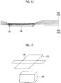
- Such a multilayer heat-insulating material is mounted on a spacecraft main body so as to cover the vicinity of the spacecraft or the mounted device on the spacecraft, and it may be necessary to repeat detachment or adjustment of a position of the rigged multilayer heat-insulating material, for an adjustment operation of the spacecraft. It is possible to efficiently perform such an operation, by applying detachable mounting means to the multilayer heat-insulating material. For example, as shown in
Fig. 12 , a method of mounting a multilayer heat-insulating material (thermal blanket) 102 on an attachment surface using a Hook-and-Loop fastener 104 has been known. -
PTL 1 shown below discloses a method of mounting a thermal blanket on an attachment surface using a Hook-and-Loop fastener (Velcro (registered trademark) tape). - [PTL 1] Japanese Unexamined Patent Application Publication No.
H9-152088 - In the multilayer heat-insulating material, a case where the heat-insulating sheets are pressed against each other, causes a thermal leakage due to thermal conduction at that portion, and this is a reason for a deterioration in heat-insulating performance. The pressed portion is easily generated in the vicinity of the mounting means of the multilayer heat-insulating material. As shown in
Fig. 12 , in a case where the Hook-and-Loop fastener 104 of the related art is used as the mounting means, the multilayer heat-insulatingmaterial 102 is stitched to the Hook-and-Loop fastener 104 through asuture 103, and accordingly, a heat-insulating sheet 102a and aspacer 102b may be pressed against each other in the vicinity of the Hook-and-Loop fastener 104. - Meanwhile, the multilayer heat-insulating
material 102 is stacked and formed by inserting thespacer 102b between the heat-insulating sheets 102a, otherwise, the heat-insulating sheets may be separated from each other, and accordingly, it is hard to handle the multilayer heat-insulating material. In a case of integrating the heat-insulating sheets by sewing, in order for ease of handling of this, the deformation to a desired shape is hardly performed. For example, in a case of covering the mounting device on a spacecraft, the deformation at a predetermined portion along a three-dimensional shape thereof may not be easily performed. In contrast, as shown inFig. 13 , it is easy to fold at a predetermined portion of atarget 109 which is an attachment target, by sewing a line to be a crease in advance to set a suturing portion, but in this case, the heat-insulating sheet 102a and thespacer 102b may be pressed against each other in the suturing portion, and the heat-insulating performance may be deteriorated. - The invention is made in view of such circumstances, and an object of the invention is to provide a multilayer heat-insulating material that prevents a deterioration in heat-insulating performance in the vicinity of mounting means and makes deformation to a desired shape easy.
- In the invention, the following means are used for achieving the objects described above.
- That is, there is provided a multilayer heat-insulating material according to one aspect of the invention, including: a heat-insulating member in which a heat-insulating sheet and a spacer are stacked; an engagement sheet provided adjacent to the heat-insulating member; a heat-insulating member engagement tool that penetrates the heat-insulating member and the engagement sheet and engages the heat-insulating member and the engagement sheet with each other; and a mounting member that is provided on the engagement sheet and is detachable from a mounting target, in which the heat-insulating member engagement tool performs the engagement so that each layer of the heat-insulating member is not adhered to each other.
- The heat-insulating member and the engagement sheet are engaged so that the heat-insulating sheet and the spacer are not adhered to each other by the heat-insulating member engagement tool. The heat-insulating member and the engagement sheet are detachably attached to the mounting target by the mounting member provided on the engagement sheet. The mounting member is provided on the engagement sheet, and accordingly, is not directly attached to the heat-insulating member. The heat-insulating member engagement tool performs the engagement so that each layer of the heat-insulating member is not adhered to each other, and accordingly, it is possible to avoid occurrence of a deterioration in heat-insulating performance due to adhesion of each layer of the heat-insulating member.
- In the multilayer heat-insulating material according to the one aspect of the invention, the heat-insulating member engagement tool includes a shank that penetrates the heat-insulating member and the engagement sheet in a stacking direction, and one pair of engagement portions that are provided on both ends of the shank, and a length of the shank is longer than a thickness, in a case where the heat-insulating member and the engagement sheet are in contact with each other, in a state where a load is not applied in the stacking direction.
- By setting the length of the shank of the heat-insulating member engagement tool to be longer than the thickness, in a case where the heat-insulating member and the engagement sheet are in contact with each other, in a state where a load is not applied in the stacking direction, it is possible to perform the engagement so that each layer of the heat-insulating member is not adhered.
- In the multilayer heat-insulating material according to the one aspect of the invention, the engagement sheet is a net-shaped or porous sheet.
- By using a net-shaped or porous sheet as the engagement sheet, it is possible to prevent a weight increase while preventing thermal conduction.
- In the multilayer heat-insulating material according to the one aspect of the invention, the engagement sheet includes a folding portion capable of forming a folding line along a predetermined direction.
- The folding portion is provided on the engagement sheet, and the folding line is formed along the predetermined direction. Therefore, it is possible to mount the multilayer heat-insulating material in accordance with the shape of the mounting target.
- In the multilayer heat-insulating material according to the one aspect of the invention, the engagement sheet includes a plurality of engagement sheet pieces, and a sheet connection portion that connects the engagement sheet pieces to each other, and the folding portion is formed by the sheet connection portion.
- The engagement sheet is divided into the plurality of engagement sheet pieces, and the sheet connection portion that connects engagement sheet piece to each other is provided. The folding portion is formed by this sheet connection portion. As the sheet connection portion, for example, an adhesion tape or a resin film is used.
- In the multilayer heat-insulating material according to the one aspect of the invention, the plurality of engagement sheet pieces have a shape corresponding to each surface of the mounting target.
- By setting each engagement sheet piece to have a shape corresponding to each surface of the mounting target, it is possible to mount the multilayer heat-insulating material according to the shape of the mounting target.
- It is possible to prevent a deterioration in heat-insulating performance in the vicinity of mounting means of the multilayer heat-insulating material and make deformation to a desired shape easy.
-
-
Fig. 1 is a perspective view showing a multilayer heat-insulating material according to a first embodiment of the invention. -
Fig. 2 is a sectional view taken along a line A-A' ofFig. 1 . -
Fig. 3 is a view showing engagement of a laminate due to insertion of a heat-insulating material engagement tool in a manufacturing method of a multilayer heat-insulating material according to the first embodiment of the invention. -
Fig. 4 is a view showing suturing of a peripheral edge portion of the heat-insulating member in the manufacturing method of a multilayer heat-insulating material according to the first embodiment of the invention. -
Fig. 5 is a view showing engagement of the heat-insulating member due to insertion of a heat-insulating member peripheral edge portion engagement tool in the manufacturing method of a multilayer heat-insulating material according to the first embodiment of the invention. -
Fig. 6 is a perspective view showing a multilayer heat-insulating material according to a second embodiment of the invention. -
Fig. 7 is a sectional view showing the multilayer heat-insulating material according to the second embodiment of the invention, and is a sectional view taken along a line B-B' ofFig. 6 . -
Fig. 8 is a sectional view showing a state where the multilayer heat-insulating material according to the second embodiment of the invention is folded. -
Fig. 9 is a sectional view showing the multilayer heat-insulating material according to a modification example of the second embodiment of the invention. -
Fig. 10 is a sectional view showing a state where the multilayer heat-insulating material according to the modification example of the second embodiment of the invention is folded. -
Fig. 11 is a perspective view showing shapes of an engagement sheet and a heat-insulating member according to the second embodiment of the invention. -
Fig. 12 is a sectional view showing an example of a multilayer heat-insulating material of the related art. -
Fig. 13 is a sectional view showing another example of the multilayer heat-insulating material of the related art. - Hereinafter, a multilayer heat-insulating material according to a first embodiment of the invention will be described with reference to the drawings.
- As shown in
Figs. 1 and 2 , a multilayer heat-insulatingmaterial 1 according to the embodiment includes a heat-insulatingmember 2, anengagement sheet 3 provided adjacent to the heat-insulating member, a mountingmember 4 fastened to theengagement sheet 3, and a heat-insulatingmember engagement tool 5. - The heat-insulating
member 2 is formed by stacking 10 to 20 layers of the heat-insulatingsheet 2a withspacers 2b interposed therebetween. As an example of the heat-insulating sheet, a film having a low emissivity, for example, or a layer obtained by performing vapor deposition of metal on a resin film having a thickness of 10 to 20 micrometers is used. As a suitable example, a layer obtained by performing vapor deposition of metal (Al, Ag, or Au) on a Kapton film having a thickness of 10 to 20 micrometers is used. The emissivity of light or electromagnetic waves is improved by performing the vapor deposition of metal, and therefore, in a case where the heat-insulating member is mounted on a mounting target 9 (spacecraft such as a rocket or an artificial satellite or a device mounted on a spacecraft) as the multilayer heat-insulating material, heat input due to radiation from the outside is prevented and heat release to the outside due to the radiation from the inside is prevented. As an example of thespacer 2b, a net-shaped member or a porous sheet-shaped member formed of a heat-insulating material is used, and particularly, a member formed of a material having a lower thermal conductivity than that of a film used in the heat-insulatingsheet 2a is preferable. - The
engagement sheet 3 is fastened by the mountingmember 4 and asuture 6. The mountingmember 4 is used in a case of mounting the multilayer heat-insulatingmaterial 1 on the mountingtarget 9. For example, a mountingmember 8 to be paired is provided on a surface of the mountingtarget 9, and the mountingmember 4 is mounted on the mountingmember 8. The mountingmember 4 is not fastened to the heat-insulatingmember 2. The mountingmember 4 is desirably repeatedly detachable mounting means, and is particularly desirable to be detached by an operation from the outside of the multilayer heat-insulatingmaterial 1. A Hook-and-Loop fastener is used as an example of the mountingmember 4, and a fastener such as a snap or a hook can also be used. Theengagement sheet 3 is repeatedly detachable from a spacecraft or a device mounted on a spacecraft by the mountingmember 4. Theengagement sheet 3 has a strength so that the engagement sheet is not damaged, even in a case where the detachment is repeated. As a suitable example of theengagement sheet 3, a material obtained by proceeding styrene, polyethylene, polypropylene, polytetrafluoroethylene, or a foaming body thereof in a sheet shape is used. As the other suitable example of theengagement sheet 3, a net-shaped sheet or a porous sheet formed of styrene, polyethylene, polypropylene, or polytetrafluoroethylene is used. - The heat-insulating
member engagement tool 5 is dispersively provided in an in-plane direction of a laminate formed of the heat-insulatingmember 2 and theengagement sheet 3. The heat-insulatingmember engagement tool 5 includes ashank 5a, and a pair ofengagement portions shank 5a. Theengagement portion 5b is provided on the outer side of theengagement sheet 3 of the laminate, and theengagement portion 5c is provided on the outer side of the heat-insulatingmember 2 of the laminate. As the heat-insulatingmember engagement tool 5, for example, a tag pin attached with a tag gun is used. As a material of the heat-insulatingmember engagement tool 5, nylon is used, for example. - The
shank 5a is provided to penetrate each layer (stacked heat-insulatingsheets 2a andspacers 2b) of the heat-insulatingmembers 2 and theengagement sheet 3. The heat-insulatingmember engagement tool 5 is formed so that a length of theshank 5a is equal to or greater than a sum of a thickness of the stacked heat-insulatingmembers 2 and a thickness of theengagement sheet 3. Accordingly, an inter-layer distance of each layer of the heat-insulatingmember 2 is not greatly narrowed by the heat-insulatingmember engagement tool 5, and the layers are not adhered to each other. Accordingly, a deterioration in heat-insulating performance due to the pressing of each layer of the heat-insulating member does not occur. The sum of the thickness of the stacked heat-insulatingmembers 2 and the thickness of theengagement sheet 3 means a thickness, in a case where the heat-insulating members are in contact with each other, in a state where a load is not applied in the stacking direction thereof, that is, a thickness in a state where the heat-insulatingmembers 2 and theengagement sheet 3 are stacked by dead load. - The
shank 5a does not bind each layer of the heat-insulatingmember 2 and theengagement sheet 3 in the stacking direction in the penetration portion of the laminate, and a relative position of theshank 5a, and each layer of the heat-insulatingmember 2 and theengagement sheet 3 can be changed in an extending direction of theshank 5a. - The
engagement portions shank 5a is provided in a direction orthogonal to theshank 5a. For example, theengagement portions shank 5a at each center in a longitudinal direction, and extends longer than a diameter of the hole in a direction orthogonal to theshank 5a from the connection portion. Therefore, the heat-insulatingmember engagement tool 5 is prevented from falling from the laminate. Theengagement portions member engagement tool 5, at the time of attachment or detachment of the multilayer heat-insulatingmaterial 1. - The heat-insulating
member engagement tool 5 is dispersively provided in a plane direction of the laminate. For example, as shown inFig. 1 , the heat-insulating member engagement tool is dispersively provided at four corners of the laminate. - As described above, the heat-insulating
member 2 is engaged to theengagement sheet 3 by the heat-insulatingmember engagement tool 5, and theengagement sheet 3 is mounted on the mountingtarget 9 by the mountingmember 4, and accordingly, it is possible to prevent reduction of heat-insulating performance by pressing of each layer of the heat-insulatingmember 2. - Next, a manufacturing method of a multilayer heat-insulating material according to the embodiment will be described.
- First, as shown in
Fig. 3 , the predetermined number of sheets of the heat-insulatingsheets 2a are stacked by insertingspacers 2b between the heat-insulatingsheets 2a, to form the heat-insulatingmember 2. The heat-insulatingsheet 2a is formed by molding a film obtained by performing vapor deposition of metal on a resin film such as Kapton, for example, in a predetermined shape. (Step 1-1) - Next, as shown in
Fig. 3 , theengagement sheet 3 is installed adjacent to the heat-insulatingmember 2, and a laminate is formed. For example, the heat-insulatingmember 2 is loaded on theengagement sheet 3, and a surface on the lower side of the heat-insulatingmember 2 and an upper surface of theengagement sheet 3 are adjacent to each other. The mountingmember 4 is fastened to theengagement sheet 3 by sewing or the like. The mountingmember 4 is fastened to a side of theengagement sheet 3 opposite to a surface adjacent to the heat-insulatingmember 2. (Step 1-2) - Next, as shown in
Fig. 3 , the heat-insulatingmember engagement tool 5 is inserted from a surface of the upper side of the heat-insulatingmember 2 of the laminate, so as to penetrate each layer of the heat-insulatingmember 2 and theengagement sheet 3. For example, a tag pin is used as the heat-insulatingmember engagement tool 5, and the tag pin is inserted from the surface of the upper side of the heat-insulatingmember 2 by using a tag gun. At this time, the heat-insulating member engagement tool may be inserted while forming a through-hole to the heat-insulatingmember 2 and theengagement sheet 3, or, in a case where a hole is formed at least a part of the heat-insulatingmember 2 and theengagement sheet 3 in advance, the heat-insulating member engagement tool may be inserted so as to penetrate this hole. (Step 1-3) - The inserted heat-insulating
member engagement tool 5 penetrates the heat-insulatingmember 2 and theengagement sheet 3, and theengagement portion 5b on a lower side of theengagement sheet 3 is deformed in a shape extending longer than a diameter of the hole in a direction orthogonal to theshank 5a from the connection portion on the connection portion with theshank 5a. Accordingly, the heat-insulatingmember engagement tool 5 is prevented from falling from the laminate, and the heat-insulatingmember 2 and theengagement sheet 3 are engaged with each other. For example, in a case of using the heat-insulatingmember engagement tool 5 including theengagement portion 5b formed of a material having elasticity and orthogonal to theshank 5a, theengagement portion 5b may be fixed in an overlapped state so as to substantially parallel to theshank 5a, the heat-insulating member engagement tool may be inserted and penetrate so as to penetrate the heat-insulatingmembers 2 and theengagement sheet 3, the fixed state may be released on the lower portion of theengagement sheet 3, the shape may be recovered by the elasticity of the heat-insulatingmember engagement tool 5, and the heat-insulatingmembers 2 and theengagement sheet 3 may be engaged. In addition, by forming theshank 5a in a smooth surface shape in the extending direction of the shank, each layer of the laminate can be slidably move along theshank 5a and can be easily deformed in a desired shape. - Step 1-3 and Step 1-4 are repeated, the predetermined number of heat-insulating
member engagement tools 5 are dispersively provided in a plane direction of the laminate, and accordingly, the heat-insulatingmember 2 is engaged with theengagement sheet 3 and the multilayer heat-insulatingmaterial 1 is integrated. For example, in a case where the heat-insulatingmember 2 has a shape of polygon in a plan view, one or more heat-insulatingmember engagement tools 5 may be dispersively provided in the vicinity of each apex thereof or dispersively provided on a peripheral edge portion along a part or the entirety of each side of the polygon. - As shown in
Fig. 2 , the integrated multilayer heat-insulatingmaterial 1 is mounted on the mountingtarget 9 through the mountingmember 4 fastened to theengagement sheet 3 and the mountingmember 8. The positions and the number of mountingmember 4 and the mountingmember 8 are suitably selected in accordance with the shape of the mountingtarget 9. For example, in a case where the mounting target is set as a tank for a rocket, the pair of the plurality of mountingmembers 4 and the mountingmembers 8 may be disposed, by considering the necessary shape of the multilayer heat-insulatingmaterial 1 and a direction of stress applied during the flight. - As shown in
Fig. 4 , Step 1-1 may further include a step of forming the heat-insulatingmember 2 by stacking the heat-insulatingsheets 2a and thespacers 2b and integrating by sewing the peripheral edge portions thereof (Step 1-1'). Accordingly, it is possible to improve handleability during the manufacturing of the multilayer heat-insulatingmaterial 1. In this step, it is suitable that the heat-insulatingmember 2 is formed to be greater than theengagement sheet 3, and the peripheral edge portions to be sewn are extended to the outer side of theengagement sheet 3 in the plane direction. In this case, a portion of the heat-insulatingmember 2 in contact with theengagement sheet 3 does not have a sewn portion, and a deterioration in heat-insulating performance due to contact of each layer of the heat-insulating member can be locally limited. Alternatively, after completing the rigging, a portion extended from the engaged sheet may be cut for each sewn portion. In this case, a contact state of each layer of the heat-insulating member generated by the sewn peripheral edge portion is alleviated. - As another modification example of Step 1-1, as shown in
Fig. 5 , a step of forming the heat-insulatingmember 2 by stacking the heat-insulatingsheets 2a and thespacers 2b, and dispersively providing a plurality of heat-insulating member peripheral edge portion engagement tools 7 on the peripheral edge portions, for integrating may be further provided (Step 1-1''). The heat-insulating member peripheral edge portion engagement tool 7 is provided to penetrate the heat-insulatingmember 2 and formed to include a heat-insulating member peripheral edge portion engagement tool shank 7a having a length equal to or greater than a thickness of the stacked and formed heat-insulatingmembers 2, and one pair of heat-insulating member peripheral edge portion engagementtool engagement portions member 2 so as to penetrate each layer of the heat-insulatingmember 2, and the heat-insulating member peripheral edge portion engagementtool engagement portion 7b on a lower side of the heat-insulatingmember 2 is deformed in a shape extending longer than a diameter of the hole in a direction orthogonal to the heat-insulating member peripheral edge portion engagement tool shank 7a from the connection portion on the connection portion with the heat-insulating member peripheral edge portionengagement tool shank 7b. This is repeated, and the predetermined number of heat-insulating member peripheral edge portion engagement tools 7 are dispersively provided in the plane direction of the heat-insulatingmember 2, for integrating the heat-insulatingmembers 2. Since the length of the heat-insulating member peripheral edge portion engagement tool shank 7a is longer than the thickness of the stacked and formed heat-insulatingmembers 2, an inter-layer distance of the heat-insulatingmember 2 is not greatly narrowed, even in a case where the heat-insulatingmembers 2 are integrated by the heat-insulating member peripheral edge portion engagement tools 7. Therefore, it is possible to improve the handleability, without deteriorating the heat-insulating performance due to the adhesion of each layer of the heat-insulatingmembers 2. As the heat-insulating member peripheral edge portion engagement tool 7, the same tool as the heat-insulatingmember engagement tool 5 described above is used, and the heat-insulating member peripheral edge portion engagement tool may be inserted into the heat-insulatingmembers 2 by the same means as the heat-insulatingmember engagement tool 5. - Hereinafter, a multilayer heat-insulating material according to a second embodiment of the invention will be described with reference to the drawings.
- A multilayer heat-insulating
material 11 according to the embodiment is shown inFigs. 6 to 11 . InFigs. 6 to 11 , the same reference numerals as inFig. 1 or 2 are used for the same constituent components as inFig. 1 or 2 , and the description thereof is omitted. - As shown in
Figs. 6 and7 , the multilayer heat-insulatingmaterial 11 according to the embodiment includes heat-insulatingmembers 12, anengagement sheet 13 provided adjacent to the heat-insulatingmember 12, the mountingmember 4 fastened to theengagement sheet 13, and the heat-insulatingmember engagement tool 5. The laminate formed of the heat-insulatingmembers 12 and theengagement sheet 13 is integrated by the heat-insulatingmember engagement tool 5. - The
engagement sheet 13 is formed of a plurality ofengagement sheet pieces 13a, and flexible sheet connection portion (folding portion) 13b connecting the plurality of engagement sheet pieces to each other. As shown inFig. 11 , theengagement sheet 13 has a shape of at least a part of surfaces configuring a development view developing a predetermined three-dimensional shape 13' surrounding the mountingtarget 9. That is, eachengagement sheet piece 13a has a shape corresponding to each surface of the mountingtarget 9. Specifically, theengagement sheet 13 is folded by thesheet connection portion 13b to have a shape so as to form the predetermined three-dimensional shape 13' surrounding the mountingtarget 9. Theengagement sheet 13 shown inFig. 11 does not include a portion corresponding to a bottom surface and has a shape so as to cover the mountingtarget 9 from the top, but may include a bottom surface and have a shape so as to cover the entirety of the mountingtarget 9. - The
engagement sheet piece 13a is a sheet piece on a flat plate formed of a material such as styrene, polyolefin, polypropylene, or polytetrafluoroethylene, and having a rigidity. In a case of deforming the multilayer heat-insulatingmaterial 11 in accordance with the shape of the mountingtarget 9, it is desirable to determine a thickness or a material so that theengagement sheet 13 maintains the shape and engages theengagement portions member engagement tool 5 without being broken. Each of theengagement sheet pieces 13a has a shape of at least one of surfaces configuring a development view developing the predetermined three-dimensional shape 13' surrounding the mountingtarget 9. The thickness or the material of theengagement sheet 13 may be locally changed. - The
sheet connection portion 13b is a flexible material connecting a peripheral edge portion and a peripheral edge portion of theengagement sheet piece 13a and theengagement sheet piece 13a is connected so as to change a relative position. For example, as an example of thesheet connection portion 13b, an adhesion tape or a resin film attached to the peripheral edge portion of theengagement sheet piece 13a is used. Thesheet connection portion 13b is formed to be more flexible than theengagement sheet piece 13a having a rigidity. Therefore, in a case of deforming the multilayer heat-insulatingmaterial 11 along the mountingtarget 9, the laminate formed of the heat-insulatingmember 12 and theengagement sheet 13 can be easily folded at a position of thesheet connection portion 13b. Thesheet connection portion 13b preferably has a structure in which thesheet connection portion 13b is mounted on the inner side of theengagement sheet 13 in a folding direction. - The heat-insulting
member 12 is formed by stacking 10 to 20 layers of the heat-insulatingsheet 12a withspacers 12b interposed therebetween, in the same manner as in the heat-insultingmember 2 of the first embodiment. The heat-insulatingmember 12 is greater than theengagement sheet 13 in a plan view, and has a shape of covering the entirety of the engagement sheet in a state where theengagement sheet 13 is folded to be inner side. For example, as shown inFig. 7 , the heat-insulatingmember 12 has the substantially the same shape as that of theengagement sheet 13 and has a shape in which the peripheral edge portion thereof is extended to the outer side of the engagement sheet in the plane direction. By setting such a shape, in a case of deforming the multilayer heat-insulatingmaterial 11 in accordance with the shape of the mountingtarget 9 by folding by thesheet connection portion 13b, it is possible to cover the mounting target with the heat-insulatingmember 12, without generating the gap and causing a deterioration in heat-insulating performance due to the pressing of each layer of the heat-insulatingmember 12. The peripheral edge portions of the heat-insulatingmembers 12 may be butt or may be overlapped. - The heat-insulating
member engagement tool 5 is dispersively provided in the in-plane direction of the laminate formed of the heat-insulatingmember 12 and theengagement sheet 13. Theshank 5a of the heat-insulatingmember engagement tool 5 is provided to penetrate each layer (stacked heat-insulatingsheets 12a andspacers 12b) of the heat-insulatingmembers 12 and theengagement sheet 13. The heat-insulatingmember engagement tool 5 is formed so that a length of theshank 5a is equal to or greater than a sum of a thickness of the stacked heat-insulatingmembers 12 and a thickness of theengagement sheet 13. Accordingly, an inter-layer distance of each layer of the heat-insulatingmember 2 is not greatly narrowed by the heat-insulatingmember engagement tool 5, and accordingly, a deterioration in heat-insulating performance due to the pressing of each layer of the heat-insulating member does not occur. The sum of the thickness of the stacked heat-insulatingmembers 12 and the thickness of theengagement sheet 13 means a thickness, in a case where the heat-insulating members are in contact with each other, in a state where a load is not applied in the stacking direction thereof, that is, a thickness in a state where the heat-insulatingmembers 12 and theengagement sheet 13 are stacked by dead load. - In a case where the thickness of the
engagement sheet 13 is locally different, a length of theshank 5a may be locally changed in advance according thereto. Theshank 5a does not bind each layer of the heat-insulatingmember 12 and theengagement sheet 13 in the stacking direction in the penetration portion of the laminate, and a relative position of theshank 5a, and each layer of the heat-insulatingmember 12 and theengagement sheet 13 can be changed in an extending direction of theshank 5a. Theengagement portions shank 5a is provided in a direction orthogonal to theshank 5a. For example, theengagement portions shank 5a at each center in a longitudinal direction, and extends longer than a diameter of the hole in a direction orthogonal to theshank 5a from the connection portion. Theengagement portions member engagement tool 5, at the time of attachment or detachment of the multilayer heat-insulatingmaterial 11. - It is suitable that the heat-insulating
member engagement tool 5 is dispersively provided in a plane direction so as to penetrate the peripheral edge portion of theengagement sheet piece 13a. The position for providing the heat-insulatingmember engagement tool 5 is determined by assuming a state where theengagement sheet 13 is folded by thesheet connection portion 13b to form the predetermined three-dimensional shape 13' surrounding the mountingtarget 9. For example, as shown inFigs. 6 and7 , the heat-insulatingmember engagement tool 5 is provided on four corners of theengagement sheet piece 13a corresponding to the top board of the three-dimensional shape 13'. Theengagement sheet piece 13a corresponding to the top board of the three-dimensional shape 13' is positioned at the center, in a case of folding theengagement sheet 13 at thesheet connection portion 13b, and the position change during the folding is small. Accordingly, the engagement sheet piece corresponds to a portion with a small change in relative position between each layer of the heat-insulatingmember 12 and theengagement sheet 13, in a case of folding the multilayer heat-insulatingmaterial 11. Accordingly, by first providing the heat-insulatingmember engagement tool 5 at four corners of theengagement sheet piece 13a corresponding to the top board of the three-dimensional shape 13' to fix the relative position with theengagement sheet 13, it is possible to efficiently engage the heat-insulatingmember 12 with theengagement sheet 13. In addition, the heat-insulatingmember engagement tool 5 is provided on the peripheral edge portion (peripheral portion on a side opposite to thesheet connection portion 13b) of eachengagement sheet piece 13a connected at the peripheral edge portion. Therefore, it is possible to integrate the multilayer heat-insulating material, regardless of the change of the relative position during the folding. - Next, the manufacturing method of the multilayer heat-insulating material according to the embodiment will be described.
- First, the predetermined three-dimensional shape 13' surrounding the mounting
target 9 is assumed and a development view developing this three-dimensional shape 13' is drawn. Eachengagement sheet piece 13a is formed in a shape shown inFig. 11 , based on the shape of each surface configuring this development view. The thickness or the material of eachengagement sheet piece 13a is selected so that theengagement sheet piece 13a maintains the shape and engages the engagement portions of the heat-insulatingmember engagement tool 5 without being broken, in a case of deforming the multilayer heat-insulatingmaterial 11 in accordance with the shape of the mountingtarget 9. The peripheral portion of each of theengagement sheet pieces 13a is connected at thesheet connection portion 13b so as to form the development view (seeFig. 7 ), and theengagement sheet 13 is formed. For example, in a case of using an adhesion tape or a resin film as thesheet connection portion 13b, the sheet connection portion is attached to the peripheral edge portion of theengagement sheet piece 13a from a side of the inner side, in a case of folding theengagement sheet 13. The mountingmember 4 is fastened to theengagement sheet 13 by sewing or the like. As a suitable example, the mountingmember 4 is fastened to theengagement sheet piece 13a positioned at the center, in a case of folding theengagement sheet 13. In addition, for mounting of the multilayer heat-insulating material, the plurality of mountingmembers 4 may be mounted on the plurality ofengagement sheet pieces 13a. (Step 2-1) - Next, as shown in
Fig. 7 , in the same manner as in the manufacturing method of the multilayer heat-insulatingmaterial 1 according to the first embodiment, the predetermined number of sheets of the heat-insulatingsheets 12a are stacked by insertingspacers 12b between the heat-insulatingsheets 12a, to form the heat-insulatingmember 12. The heat-insulatingsheet 12a is formed by molding a film obtained by performing vapor deposition of metal on a resin film such as Kapton, for example, in a predetermined shape. The shape of theheat0insulating sheet 12a is the substantially the same shape as that of theengagement sheet 13 and a shape in which the peripheral edge portion thereof is extended to the outer side of the engagement sheet in the plane direction. (Step 2-2) - Next, as shown in
Fig. 7 , theengagement sheet 13 is installed adjacent to the heat-insulatingmember 12, and a laminate is formed. For example, the heat-insulatingmember 12 is loaded on theengagement sheet 13, and a surface on the lower side of the heat-insulatingmember 12 and an upper surface of theengagement sheet 13 are adjacent to each other. The mountingmember 4 is disposed on a side of theengagement sheet 13 opposite to a surface adjacent to the heat-insulatingmember 12. (Step 2-3) - Next, as shown in
Fig. 7 , in the same manner as in the manufacturing method of the multilayer heat-insulatingmaterial 1 according to the first embodiment, the heat-insulatingmember engagement tool 5 is inserted from a surface of the upper side of the heat-insulatingmember 12 of the laminate, so as to penetrate each layer of the heat-insulatingmember 12 and theengagement sheet 13. For example, a tag pin is used as the heat-insulatingmember engagement tool 5, and the tag pin is inserted from the surface of the upper side of the heat-insulatingmember 12 by using a tag gun. At this time, the heat-insulating member engagement tool may be inserted while forming a through-hole to the heat-insulatingmember 12 and theengagement sheet 13, or, in a case where a hole is formed at least a part of the heat-insulatingmember 12 and theengagement sheet 13 in advance, the heat-insulating member engagement tool may be inserted so as to penetrate this hole. (Step 2-4) - The inserted heat-insulating
member engagement tool 5 penetrates the heat-insulatingmember 12 and theengagement sheet 13, and theengagement portion 5b on a lower side of theengagement sheet 13 is deformed in a shape extending longer than a diameter of the hole in a direction orthogonal to theshank 5a from the connection portion on the connection portion with theshank 5a. Accordingly, the heat-insulatingmember engagement tool 5 is prevented from falling from the laminate, and the heat-insulatingmember 12 and theengagement sheet 13 are engaged with each other. By forming theshank 5a in a smooth surface shape in the extending direction of the shank, each layer of the laminate can be slidably move along theshank 5a and can be easily deformed in a desired shape. (Step 2-5) - Step 2-4 and Step 2-5 are repeated, the predetermined number of heat-insulating
member engagement tools 5 are dispersively provided in a plane direction of the laminate, and accordingly, the heat-insulatingmember 12 is engaged with theengagement sheet 13 and the multilayer heat-insulatingmaterial 11 is integrated. As a suitable example, first, the heat-insulatingmember engagement tool 5 is provided on four corners of theengagement sheet piece 13a corresponding to the top board of the three-dimensional shape 13', and the heat-insulatingmember engagement tool 5 is also provided on the peripheral edge portion (peripheral portion on a side opposite to thesheet connection portion 13b) of eachengagement sheet piece 13a connected at the peripheral edge portion. Therefore, it is possible to integrate the multilayer heat-insulating material, regardless of the change of the relative position during the folding. - In a case where the
engagement sheet 13 is folded to have a shape of a protrusion to the outer side in the inner side, the position for forming the heat-insulatingmember engagement tool 5 is determined, by assuming that the layer of the heat-insulatingmember 12 on the outer side has a radius of curvature greater than that of the layer on the inner side. As a suitable example, as shown inFig. 7 , the heat-insulatingmember engagement tool 5 is provided on four corners of theengagement sheet piece 13a corresponding to the top board of the three-dimensional shape 13' in a substantially vertical direction (stacking direction), and a heat-insulating member engagement tool 5' having alonger shank 5a' is provided obliquely to the stacking direction in the portion extending from a predetermined folding position, so that the layer on the outer side penetrates the position moved forward (position separated) from the predetermined folding position. As described above, by adjusting the position for providing the heat-insulating member engagement tool 5', as shown inFig. 8 , even in a case where the multilayer heat-insulatingmaterial 11 is deformed in accordance with the shape of the mountingtarget 9, the layers of the heat-insulatingmember 12 are not pressed. As shown inFig. 9 , the length of theshank 5a' of the heat-insulating member engagement tool 5' is sufficiently ensured in advance, and the heat-insulating member engagement tool 5' may be substantially vertically provided in the portion extended from the predetermined folding position. In this case, as shown inFig. 10 , in a case where the multilayer heat-insulatingmaterial 11 is deformed in accordance with the shape of the mountingtarget 9, the heat-insulating member engagement tool 5' has a shape penetrating the heat-insulatingmember 12 obliquely to the stacking direction. - The integrated multilayer heat-insulating
material 11 is mounted on the mountingtarget 9 by connecting the mountingmember 4 fastened to theengagement sheet 13 and the mountingmember 8 on the facing side. At the time of the mounting, theengagement sheet 13 is folded so as to form the predetermined three-dimensional shape 13', and accordingly, the multilayer heat-insulatingmaterial 11 is deformed in accordance with the shape of the mountingtarget 9. The positions and the number of mountingmember 4 and the mountingmember 8 are suitably selected in accordance with the shape of the mountingtarget 9. - In the same manner as in the manufacturing method of the multilayer heat-insulating
material 1 according to the first embodiment, Step 2-2 may further include a step of forming the heat-insulatingmember 12 by stacking the heat-insulatingsheets 12a and thespacers 12b and integrating by sewing the peripheral edge portions thereof (Step 2-2'). In this step, it is suitable that the heat-insulatingmember 12 is formed to be greater than theengagement sheet 13, and the peripheral edge portions to be sewn are extended to the outer side of theengagement sheet 13 in the plane direction. In addition, after completing the rigging, a portion extended from the engaged sheet may be cut for each sewn portion. In this case, a contact state of each layer of the heat-insulating member generated by the sewn peripheral edge portion is alleviated. - In the same manner as in the manufacturing method of the multilayer heat-insulating
material 1 according to the first embodiment, Step 2-2 may further include a step of forming the heat-insulatingmember 12 by stacking the heat-insulatingsheets 12a and thespacers 12b, and dispersively providing a plurality of heat-insulating member peripheral edge portion engagement tools 7 on the peripheral edge portions, for integrating (Step 2-2''). The heat-insulating member peripheral edge portion engagement tool 7 is inserted from a surface of the upper side of the heat-insulatingmember 12 so as to penetrate each layer of the heat-insulatingmember 12, and the heat-insulating member peripheral edge portion engagementtool engagement portion 7b on a lower side of the heat-insulatingmember 2 is deformed in a shape extending longer than a diameter of the hole in a direction orthogonal to the heat-insulating member peripheral edge portion engagement tool shank 7a from the connection portion on the connection portion with the heat-insulating member peripheral edge portion engagement tool shank 7a. This is repeated, and the predetermined number of heat-insulating member peripheral edge portion engagement tools 7 are dispersively provided in the plane direction of the heat-insulatingmember 2, for integrating the heat-insulatingmembers 2. As the heat-insulating member peripheral edge portion engagement tool 7, the same tool as the heat-insulatingmember engagement tool 5 described above is used, and the heat-insulating member peripheral edge portion engagement tool may be inserted into the heat-insulatingmembers 12 by the same means as the heat-insulatingmember engagement tool 5. - In the embodiments described above, the plurality of
engagement sheet pieces 13a are connected by thesheet connection portion 13b and theengagement sheet 13 is folded by thesheet connection portion 13b, but theengagement sheet 13 may not be divided and a line of folding may be drawn with scratch or hollow. -
- 1, 11: multilayer heat-insulating material
- 2, 12: heat-insulating member
- 2a, 12a: heat-insulating sheet
- 2b, 12b: spacer
- 3, 13: engagement sheet
- 4: mounting member
- 5, 5': heat-insulating member engagement tool
- 5a, 5a': shank
- 5b, 5c: engagement portion
- 6: suture
- 7: heat-insulating member peripheral edge portion engagement tool
- 7a: heat-insulating member peripheral edge portion engagement tool shank
- 7b, 7c: heat-insulating member peripheral edge portion engagement tool engagement portion
- 8: mounting member
- 9: mounting target
- 13a: engagement sheet piece
- 13b: sheet connection portion (folding portion)
Claims (6)
- A multilayer heat-insulating material, comprising:a heat-insulating member in which a heat-insulating sheet and a spacer are stacked;an engagement sheet provided adjacent to the heat-insulating member;a heat-insulating member engagement tool that penetrates the heat-insulating member and the engagement sheet and engages the heat-insulating member and the engagement sheet with each other; anda mounting member that is provided on the engagement sheet and is detachable from a mounting target,wherein the heat-insulating member engagement tool performs the engagement so that each layer of the heat-insulating member is not adhered to each other.
- The multilayer heat-insulating material according to claim 1,
wherein the heat-insulating member engagement tool includes a shank that penetrates the heat-insulating member and the engagement sheet in a stacking direction, and one pair of engagement portions that is provided on both ends of the shank, and
a length of the shank is longer than a thickness thereof, in a case where the heat-insulating member and the engagement sheet are in contact with each other, in a state where a load is not applied in the stacking direction. - The multilayer heat-insulating material according to claim 1 or 2,
wherein the engagement sheet is a net-shaped or porous sheet. - The multilayer heat-insulating material according to any one of claims 1 to 3,
wherein the engagement sheet includes a folding portion capable of forming a folding line along a predetermined direction. - The multilayer heat-insulating material according to claim 4,
wherein the engagement sheet includes a plurality of engagement sheet pieces, and a sheet connection portion that connects the engagement sheet pieces to each other, and
the folding portion is formed by the sheet connection portion. - The multilayer heat-insulating material according to claim 5,
wherein the plurality of engagement sheet pieces have a shape corresponding to each surface of the mounting target.
Applications Claiming Priority (2)
| Application Number | Priority Date | Filing Date | Title |
|---|---|---|---|
| JP2017114553A JP6862289B2 (en) | 2017-06-09 | 2017-06-09 | Multi-layer insulation |
| PCT/JP2018/021380 WO2018225688A1 (en) | 2017-06-09 | 2018-06-04 | Multilayer heat-insulating material |
Publications (2)
| Publication Number | Publication Date |
|---|---|
| EP3587890A1 true EP3587890A1 (en) | 2020-01-01 |
| EP3587890A4 EP3587890A4 (en) | 2021-01-20 |
Family
ID=64565820
Family Applications (1)
| Application Number | Title | Priority Date | Filing Date |
|---|---|---|---|
| EP18813436.5A Withdrawn EP3587890A4 (en) | 2017-06-09 | 2018-06-04 | Multilayer heat-insulating material |
Country Status (4)
| Country | Link |
|---|---|
| US (1) | US20200094996A1 (en) |
| EP (1) | EP3587890A4 (en) |
| JP (1) | JP6862289B2 (en) |
| WO (1) | WO2018225688A1 (en) |
Families Citing this family (5)
| Publication number | Priority date | Publication date | Assignee | Title |
|---|---|---|---|---|
| CN111891408A (en) * | 2020-06-30 | 2020-11-06 | 北京空间飞行器总体设计部 | Multilayer heat insulation assembly system for increasing heat insulation effect of spacecraft |
| CN112208802B (en) * | 2020-09-09 | 2022-07-12 | 航天科工空间工程发展有限公司 | Multilayer heat insulation assembly |
| CN112265862B (en) * | 2020-10-26 | 2024-05-31 | 徐正强 | Folding use structure of heat preservation cotton and similar products |
| CN113071718B (en) * | 2021-02-26 | 2023-06-02 | 北京空间飞行器总体设计部 | Lunar surface take-off lifter heat protection device and heat insulation performance calculation method thereof |
| EP4402706A1 (en) * | 2022-08-05 | 2024-07-24 | Zenno Astronautics Limited | An improved satellite system |
Family Cites Families (19)
| Publication number | Priority date | Publication date | Assignee | Title |
|---|---|---|---|---|
| JPS6135832U (en) * | 1984-08-03 | 1986-03-05 | 積水化成品工業株式会社 | Synthetic resin laminated insulation material |
| JPH056115Y2 (en) * | 1988-02-26 | 1993-02-17 | ||
| GB9020428D0 (en) * | 1990-09-19 | 1990-10-31 | Gore W L & Ass Uk | Thermal control materials |
| JPH04134000U (en) * | 1991-06-03 | 1992-12-14 | 日本電気エンジニアリング株式会社 | thermal blanket |
| JPH09152088A (en) * | 1995-12-04 | 1997-06-10 | Nec Eng Ltd | Thermal blanket |
| AUPP483298A0 (en) * | 1998-07-23 | 1998-08-13 | Bains Harding Limited | Insulation module for vessels |
| JP2000072100A (en) * | 1998-08-27 | 2000-03-07 | Ishikawajima Harima Heavy Ind Co Ltd | Grounding structure of multi-layered heat insulating material |
| JP4155347B2 (en) * | 1998-09-04 | 2008-09-24 | Necエンジニアリング株式会社 | Electrical continuity processing method of thermal blanket |
| JP2002337800A (en) * | 2001-05-21 | 2002-11-27 | Nec Corp | Thermal blanket |
| JP4261966B2 (en) * | 2003-04-16 | 2009-05-13 | Nbc株式会社 | Air conditioner outdoor unit heat insulation cover |
| JP4549909B2 (en) * | 2005-03-25 | 2010-09-22 | 三菱電機株式会社 | Thermal blanket for satellite and its mounting method |
| JP4963840B2 (en) * | 2006-02-07 | 2012-06-27 | 積水化成品工業株式会社 | Insulating cover and article storage method and delivery method using the same |
| JP2008082039A (en) * | 2006-09-28 | 2008-04-10 | Mimo Material Kk | Thermal insulation material |
| JP5351112B2 (en) * | 2009-09-02 | 2013-11-27 | ニチアス株式会社 | Insulation |
| JP2012132494A (en) * | 2010-12-21 | 2012-07-12 | Ihi Aerospace Co Ltd | Multilayer heat insulating material |
| JP5972665B2 (en) * | 2012-05-17 | 2016-08-17 | 名古屋油化株式会社 | Thermal insulation and sound absorption material |
| JP2014184875A (en) * | 2013-03-25 | 2014-10-02 | Mitsubishi Electric Corp | Multi-layer heat insulator |
| JP6634265B2 (en) * | 2015-10-21 | 2020-01-22 | 株式会社トスカバノック | Method for fixing and fixing heat insulating material and its structure |
| CN106626676A (en) * | 2017-01-23 | 2017-05-10 | 江苏泛亚微透科技股份有限公司 | Composite material of heat insulation and sound insulation aerogel layer composite breathable membrane and manufacturing method thereof |
-
2017
- 2017-06-09 JP JP2017114553A patent/JP6862289B2/en active Active
-
2018
- 2018-06-04 US US16/498,096 patent/US20200094996A1/en not_active Abandoned
- 2018-06-04 EP EP18813436.5A patent/EP3587890A4/en not_active Withdrawn
- 2018-06-04 WO PCT/JP2018/021380 patent/WO2018225688A1/en unknown
Also Published As
| Publication number | Publication date |
|---|---|
| WO2018225688A1 (en) | 2018-12-13 |
| EP3587890A4 (en) | 2021-01-20 |
| US20200094996A1 (en) | 2020-03-26 |
| JP2018204781A (en) | 2018-12-27 |
| JP6862289B2 (en) | 2021-04-21 |
Similar Documents
| Publication | Publication Date | Title |
|---|---|---|
| EP3587890A1 (en) | Multilayer heat-insulating material | |
| US7371304B2 (en) | Apparatuses and methods for joining structural members, such as composite structural members | |
| US20180245610A1 (en) | Curtain Retention Bracket | |
| EP3085616B1 (en) | Embedded tear strips in metal structures | |
| US20170100884A1 (en) | Fiber composite component assembly having at least two plate-shaped composite structures and processes for preparing same | |
| US9856061B2 (en) | Low profile, wrappable elongate members spacer and method of maintaining elongate members in fixed, spaced relative relation | |
| EP3614373B1 (en) | Multi-degree of freedom acoustic panel | |
| EP3196113A1 (en) | Barrier structure for corner portion of cargo hold and method for installing barrier for corner portion of cargo hold | |
| WO2013060916A9 (en) | Aircraft components having optimised stringer run-out zones | |
| KR20150104085A (en) | Method of fabricating a curved composite structure using composite prepreg tape | |
| JP2007229980A (en) | Frp joint structure | |
| KR102140346B1 (en) | Composite hat stiffener | |
| JP6238168B2 (en) | Composite structure | |
| EP3450302B1 (en) | Energy-absorbing under-floor airframe | |
| US20160129677A1 (en) | Film for sealing vents | |
| JP2017078470A (en) | Structure of heat insulator, stopping and fixing method for heat insulator, and structure therefor | |
| CN112208802B (en) | Multilayer heat insulation assembly | |
| JP3888634B2 (en) | Connecting structure of solar cells | |
| US9610658B2 (en) | Reel feed clinching tack pins | |
| JP2019098926A (en) | Heat control covering member of spacecraft | |
| US11518495B2 (en) | Composite structural elements | |
| US11298893B2 (en) | Method for manufacturing structure using composite material | |
| EP1099537A1 (en) | Reinforcement of a laminated member for an aircraft | |
| CA3014235C (en) | Energy-absorbing under-floor airframe | |
| GB2104833A (en) | Flexible sheet with fixing device |
Legal Events
| Date | Code | Title | Description |
|---|---|---|---|
| STAA | Information on the status of an ep patent application or granted ep patent |
Free format text: STATUS: THE INTERNATIONAL PUBLICATION HAS BEEN MADE |
|
| PUAI | Public reference made under article 153(3) epc to a published international application that has entered the european phase |
Free format text: ORIGINAL CODE: 0009012 |
|
| STAA | Information on the status of an ep patent application or granted ep patent |
Free format text: STATUS: REQUEST FOR EXAMINATION WAS MADE |
|
| 17P | Request for examination filed |
Effective date: 20190925 |
|
| AK | Designated contracting states |
Kind code of ref document: A1 Designated state(s): AL AT BE BG CH CY CZ DE DK EE ES FI FR GB GR HR HU IE IS IT LI LT LU LV MC MK MT NL NO PL PT RO RS SE SI SK SM TR |
|
| AX | Request for extension of the european patent |
Extension state: BA ME |
|
| DAV | Request for validation of the european patent (deleted) | ||
| DAX | Request for extension of the european patent (deleted) | ||
| A4 | Supplementary search report drawn up and despatched |
Effective date: 20201222 |
|
| RIC1 | Information provided on ipc code assigned before grant |
Ipc: F16L 59/02 20060101AFI20201216BHEP Ipc: B64C 1/06 20060101ALI20201216BHEP Ipc: B64G 1/58 20060101ALI20201216BHEP |
|
| GRAP | Despatch of communication of intention to grant a patent |
Free format text: ORIGINAL CODE: EPIDOSNIGR1 |
|
| STAA | Information on the status of an ep patent application or granted ep patent |
Free format text: STATUS: GRANT OF PATENT IS INTENDED |
|
| RIC1 | Information provided on ipc code assigned before grant |
Ipc: F16L 59/02 20060101AFI20210414BHEP Ipc: B64G 1/58 20060101ALI20210414BHEP Ipc: B64C 1/06 20060101ALI20210414BHEP |
|
| INTG | Intention to grant announced |
Effective date: 20210514 |
|
| STAA | Information on the status of an ep patent application or granted ep patent |
Free format text: STATUS: THE APPLICATION HAS BEEN WITHDRAWN |
|
| 18W | Application withdrawn |
Effective date: 20210624 |