WO2018225657A1 - 冷凍装置の熱源ユニット - Google Patents
冷凍装置の熱源ユニット Download PDFInfo
- Publication number
- WO2018225657A1 WO2018225657A1 PCT/JP2018/021244 JP2018021244W WO2018225657A1 WO 2018225657 A1 WO2018225657 A1 WO 2018225657A1 JP 2018021244 W JP2018021244 W JP 2018021244W WO 2018225657 A1 WO2018225657 A1 WO 2018225657A1
- Authority
- WO
- WIPO (PCT)
- Prior art keywords
- muffler
- heat source
- pipe
- refrigerant
- connection
- Prior art date
- Legal status (The legal status is an assumption and is not a legal conclusion. Google has not performed a legal analysis and makes no representation as to the accuracy of the status listed.)
- Ceased
Links
Images



Classifications
-
- F—MECHANICAL ENGINEERING; LIGHTING; HEATING; WEAPONS; BLASTING
- F24—HEATING; RANGES; VENTILATING
- F24F—AIR-CONDITIONING; AIR-HUMIDIFICATION; VENTILATION; USE OF AIR CURRENTS FOR SCREENING
- F24F1/00—Room units for air-conditioning, e.g. separate or self-contained units or units receiving primary air from a central station
- F24F1/06—Separate outdoor units, e.g. outdoor unit to be linked to a separate room comprising a compressor and a heat exchanger
- F24F1/46—Component arrangements in separate outdoor units
-
- F—MECHANICAL ENGINEERING; LIGHTING; HEATING; WEAPONS; BLASTING
- F25—REFRIGERATION OR COOLING; COMBINED HEATING AND REFRIGERATION SYSTEMS; HEAT PUMP SYSTEMS; MANUFACTURE OR STORAGE OF ICE; LIQUEFACTION SOLIDIFICATION OF GASES
- F25B—REFRIGERATION MACHINES, PLANTS OR SYSTEMS; COMBINED HEATING AND REFRIGERATION SYSTEMS; HEAT PUMP SYSTEMS
- F25B41/00—Fluid-circulation arrangements
Definitions
- the present disclosure relates to a heat source unit of a refrigeration apparatus.
- Patent Document 1 Japanese Utility Model Publication No. 1-1534275 discloses that a muffler is directly connected to a gas pipe header.
- the problem of the present disclosure is to reduce the size of the heat source unit of the refrigeration apparatus having good quietness.
- a plurality of usage units including the first usage unit and the second usage unit are connected via a plurality of communication piping including the first communication piping and the second communication piping.
- a second connecting part a common refrigerant pipe through which a refrigerant flowing through the first connecting part and a refrigerant flowing through the second connecting part flow together, and the first connecting part to the refrigerant pipe;
- the two mufflers are the first muffler and the second muffler Refrigerant flow direction are both inclined relative to the horizontal direction with respect to the vertical direction in the la.
- the flow direction of the refrigerant in the first muffler and the second muffler is inclined with respect to the vertical direction and the horizontal direction.
- the vertical occupied area is shorter than when the refrigerant flow direction is vertical, or the horizontal occupied areas of the first muffler and the second muffler are shorter than when the refrigerant flow direction is horizontal. .
- the first muffler and the second muffler are both cylindrical and the refrigerant flows in a direction along the central axis. Is.
- the size of the first muffler and the second muffler in which the refrigerant flows in the direction along the central axis tends to be longer in the refrigerant flow direction.
- the refrigerant flow direction of the second muffler is inclined both in the vertical direction and in the horizontal direction, so that the occupied area of the plurality of mufflers can be prevented from increasing in the vertical direction and the horizontal direction.
- the heat source unit of the refrigeration apparatus is the heat source unit of the first aspect or the second aspect, connected to a common refrigerant pipe, and flowing through the first connection part and the refrigerant flowing through the second connection part.
- a common refrigerant pipe is connected to the merger, the merger and the first muffler, and are connected to the first connection pipe having the first straight pipe part, and the merger and the second muffler, and have the second straight pipe part.
- 2 connection piping, the 1st thermistor attached to the 1st straight piping part, and the 2nd thermistor attached to the 2nd straight piping part are further provided.
- the first straight pipe portion is connected to the first connection pipe connected to the merger and the first muffler and the second connection pipe connected to the merger and the second muffler.
- the first connecting piping and the second connecting piping are three-dimensionally piped in a small space, and the first straight piping portion and the second straight piping portion are placed in a small piping space. Can fit.
- the heat source unit of the refrigeration apparatus is the heat source unit according to the third aspect, wherein each of the first straight pipe part and the second straight pipe part has a length of 20 mm or more. .
- the heat source unit since the first thermistor and the second thermistor are attached to the first straight pipe part and the second straight pipe part having a length of 20 mm or more, the gas returning from each utilization unit The temperature of the refrigerant can be stably detected by the heat source unit.
- the heat source unit of the refrigeration apparatus is connected to a third usage unit different from the first usage unit and the second usage unit in any one of the heat source units according to the first to fourth aspects.
- a third connection part that is a connection destination of the third connection pipe, and a third muffler that is provided between the third connection part and the refrigerant pipe and reduces the pulsation of the refrigerant flowing through the third connection part,
- the 3 muffler is such that the refrigerant flow direction in the third muffler is inclined along the refrigerant flow direction in the first muffler and the second muffler.
- the heat source unit since the refrigerant flow direction in the third muffler is inclined along the refrigerant flow direction in the first muffler and the second muffler, the vertical direction of the first muffler to the third muffler The occupied area is shorter than when the refrigerant flow direction is the vertical direction, or the horizontal occupied areas of the first to third mufflers are shorter than when the refrigerant flow direction is the horizontal direction.
- the heat source unit of the refrigeration apparatus is the heat source unit according to the fifth aspect, in which the first connection portion, the second connection portion, and the third connection portion are sequentially arranged, and the first connection portion and the second connection are arranged.
- the distance between the first and second mufflers is less than 130% of the shorter length of the first muffler and the second muffler, and the shorter of the second and third mufflers the distance between the second and third connection parts
- the muffler length is less than 130%.
- the first muffler, the second muffler, and the third muffler are arranged to be inclined, and the distance between the first connection portion and the second connection portion, and the second connection portion and the third connection. Since the distance between the portions can be less than 130% of the shorter muffler length, the length from the first connection portion to the third connection portion can be shortened.
- the heat source unit of the refrigeration apparatus is the heat source unit according to any one of the first to sixth aspects, wherein the first muffler and the second muffler from the first connection part and the second connection part in a top view. And a casing having a front plate disposed at a distance of less than 250% of the length of the muffler in the extending direction, and housing the common refrigerant pipe, the first muffler, and the second muffler.
- the front plate is disposed at a distance of less than 250% of the muffler length from the first connection portion and the second connection portion, the length of the heat source unit in the front-rear direction is shortened. it can.
- a heat source unit of a refrigeration apparatus is the heat source unit according to any one of the first to seventh aspects, further including a compressor that sucks refrigerant flowing through a common refrigerant pipe, and the first connection unit And from the 2nd connection part to refrigerant piping is a gas pipe which returns to a compressor.
- the heat source unit since the gas pipe returning from the first connection part and the second connection part to the common refrigerant pipe returns to the compressor, it is not necessary to consider problems such as refrigerant drift Therefore, the restrictions imposed on the pipes from the first connection part and the second connection part to the common refrigerant pipe are reduced.
- the heat source unit of the refrigeration apparatus according to the first aspect, the fifth aspect, or the sixth aspect of the present disclosure, it is possible to reduce the size of the heat source unit with good quietness.
- the installation space for the plurality of mufflers can be reduced while obtaining high silence.
- the heat source unit of the refrigeration apparatus it is possible to provide a space for attaching the first thermistor and the second thermistor while suppressing expansion of the piping space.
- the heat source unit of the refrigeration apparatus can be significantly reduced in size.
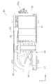
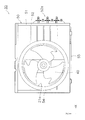
- the circuit diagram of the freezing apparatus containing the heat-source unit which concerns on embodiment The top view which shows the heat-source unit which concerns on embodiment in the state which removed the top plate etc.
- the front view which shows the heat-source unit of FIG. 1 in the state which removed the grid, the heat exchanger, etc.
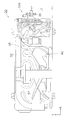
- FIG. The top view which shows the heat-source unit of FIG. 2 in the state which removed the electrical component box etc. further.
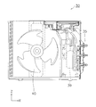
- the front view of the heat-source unit of the state shown by FIG. The enlarged front view which expands and shows a muffler and its surrounding structure.
- the enlarged side view which expands and shows the muffler and its surrounding structure.
- the refrigeration apparatus 10 shown in FIG. 1 includes a plurality of usage units 20 and a heat source unit 30 connected to the usage units 20.
- three usage units 20 are shown, but the number of usage units 20 to which the present disclosure can be applied is not limited to three.
- the usage unit 20 and the heat source unit 30 are connected by connecting pipes 12 and 13, and a refrigerant circuit 11 for circulating the refrigerant between the plurality of usage units 20 and the heat source unit 30 connected in parallel is formed. Yes. As the refrigerant circulates through the refrigerant circuit 11, the refrigeration apparatus 10 can perform a vapor compression refrigeration cycle.
- each use unit 20 includes a use-side heat exchanger 21.
- the heat source unit 30 includes a compressor 31, a heat source side heat exchanger 32, a plurality of expansion valves 33, a liquid side closing valve 34, a gas side closing valve 35, a muffler 36, a merger 37, a muffler 38, and an accumulator 39. I have.
- the number of the expansion valves 33, the liquid side closing valves 34, the gas side closing valves 35, and the closing valve side mufflers 36 are three each, which is the same number as the usage units 20.
- an electric valve can be used as the expansion valve 33.
- the refrigerant circuit 11 is configured so that the refrigerant circulates in the order of the accumulator 39.
- the compressor 31 compresses the gas refrigerant sucked from the accumulator 39.
- the high-temperature and high-pressure refrigerant that has exited from the discharge port of the compressor 31 flows into the inlet of the heat source side heat exchanger 32.
- the refrigerant that has exchanged heat with the outdoor air in the heat source side heat exchanger 32 flows out from the outlet of the heat source side heat exchanger 32 and flows into the inlet of the expansion valve 33.
- the refrigerant expanded and decompressed by the expansion valve 33 flows out from the outlet of the expansion valve 33 and flows into the inlet of the use side heat exchanger 21 via the liquid side closing valve 34 and the communication pipe 12.
- the gas refrigerant heat-exchanged with the indoor air in the use side heat exchanger 21 flows out from the outlet of the use side heat exchanger 21, and is connected to the communication pipe 13, the gas side closing valve 35, and the closing valve side muffler 36. Then, the air flows into the suction port of the compressor 31 through the merger 37, the common muffler 38 and the accumulator 39.
- the refrigeration apparatus consumes power from the compressor 31 as in the air conditioner shown in FIG. 1, and starts from one of the heat source side heat exchanger 32 and the use side heat exchanger 21. It is a device that takes in heat and discharges heat from the other.
- the refrigeration apparatus is an apparatus that performs a refrigeration cycle in a refrigerant circuit.
- the refrigeration apparatus includes, for example, a heat pump water heater that supplies hot water, a refrigerator, and a cooling device that cools the interior of the refrigerator.
- the use-side heat exchanger 21 is an air heat exchanger that exchanges heat between air and a refrigerant, and is, for example, a cross-fin type fin-and-tube heat composed of a heat transfer tube and a large number of fins. It is an exchanger.
- heat exchange is performed between the refrigerant of the refrigerant circuit 11 flowing in the tube (heat transfer tube) and the indoor air passing between the fins. Therefore, the use side heat exchanger 21 functions as a refrigerant evaporator during cooling operation to cool the room air.
- the usage-side fan 22 of the usage unit 20 sucks room air into the casing 29 and exchanges heat with the refrigerant in the usage-side heat exchanger 21, and then supplies the air after heat exchange to the room as supply air. Function as.
- the heat source unit 30 includes a casing 50, and in the casing 50, a compressor 31, a heat source side heat exchanger 32, a plurality of expansion valves 33, and a plurality of liquids.
- Side closing valve 34 a plurality of gas side closing valves 35, a plurality of mufflers 36, a merger 37, a muffler 38, an accumulator 39, a heat source side fan 40, an electrical component box 41, a discharge temperature sensor 91, an outdoor temperature sensor 92, and a heat source side.
- a heat exchanger temperature sensor 93 and a suction temperature sensor 94 are provided.
- the compressor 31 provided in the heat source unit 30 is a positive displacement compressor whose operating capacity can be changed according to the rotational speed (operating frequency). For example, a motor (not shown) whose rotational speed is controlled by an inverter. Thus, the rotational speed of the compressor 31 is controlled.
- the heat source side fan 40 sends outside air around the casing 50 of the heat source unit 30 to the heat source side heat exchanger 32.
- the heat source side fan 40 is a fan capable of changing the air volume of air supplied to the heat source side heat exchanger 32, and is a propeller fan or the like driven by a motor (not shown). Operation control of the compressor 31, the expansion valve 33, and the heat source side fan 40 is performed by a heat source side control device housed in the electrical component box 41.
- the heat source side heat exchanger 32 heat exchange is performed between the outside air flowing into the heat source unit 30 and the refrigerant compressed by the compressor 31.
- the heat source side heat exchanger 32 is, for example, a cross-fin type fin-and-tube heat exchanger, and heat between the refrigerant passing through the tube (heat transfer tube) and the outside air passing between the plurality of fins. Exchange. That is, the heat source side heat exchanger 32 functions as a radiator during cooling operation. Heat is released from the refrigerant while passing through the heat source side heat exchanger 32, and the gas refrigerant changes into a liquid refrigerant through a gas-liquid two-phase state. The air heat exchanged by the heat source side heat exchanger 32 is blown out of the heat source unit 30.
- the discharge temperature sensor 91 is attached to the discharge pipe of the compressor 31, for example, and detects the temperature of the refrigerant discharged from the compressor 31.
- the outdoor temperature sensor 92 detects the ambient temperature of the outdoor air that the heat source side fan 40 takes into the casing 50 of the heat source unit 30.
- the heat source side heat exchanger temperature sensor 93 detects the temperature of the part in the gas-liquid two-phase state in the heat source side heat exchanger 32.
- Each suction temperature sensor 94 detects the temperature of the gas refrigerant returned from the corresponding usage unit 20.
- the refrigeration apparatus 10 controls the state of the refrigerant flowing through the refrigerant circuit 11 according to the detection results of the discharge temperature sensor 91, the outdoor temperature sensor 92, the heat source side heat exchanger temperature sensor 93, and the suction temperature sensor 94.
- a thermistor can be used as the discharge temperature sensor 91, the outdoor temperature sensor 92, the heat source side heat exchanger temperature sensor 93, and the suction temperature sensor 94.
- FIG. 2 shows an internal view of the heat source unit 30 according to the embodiment of the present disclosure when the heat source unit 30 is removed from the top. It is shown.
- the appearance of the heat source unit when the heat source unit 30 shown in FIG. 2 is viewed from the front is shown in FIG. FIG. 2 shows a state in which the top plate and a grid provided on the front face of the unit to ensure safety are removed.
- the heat source unit 30 has an appearance based on a rectangular parallelepiped shape having a side along the Z-axis extending in the vertical direction, a side along the Y-axis extending in the front-rear direction, and a side along the X-axis direction extending in the left-right direction.
- a casing 50 is provided.
- a top plate that is bent downward around a rectangular metal plate that is long in the left-right direction (X-axis direction) and short in the front-rear direction (Y-axis direction) is located on the top surface of the casing 50.
- Metal plates are also arranged on the other five surfaces of the casing 50.
- a circular opening 21a is formed in the central portion of the front plate 51 of the casing 50 disposed on the front surface of the unit.
- the right side plate 52 of the casing 50 arranged on the right side surface of the unit is provided with a connection portion 52a for connecting the use unit 20 and circulating the refrigerant.
- the right side plate 52 is bent substantially at a right angle and also covers a part of the rear side of the unit.
- a large rectangular opening 53 is formed on the rear surface of the unit.
- An opening (not shown) for sucking air into the heat source unit 30 is also formed in the left side plate 54 of the casing 50 disposed on the left side of the unit.
- the bottom of the casing 50 is covered with a metal bottom frame 55.
- the heat source side heat exchanger 32 is arranged from the rear face of the unit to the left side face of the unit.
- the air sucked into the heat source unit 30 from the outside through the opening 53 on the rear side of the unit and the opening of the left side plate 54 passes through the heat source side heat exchanger 32.
- the airflow passing through the heat source side heat exchanger 32 is generated by the heat source side fan 40.
- FIG. 4 shows a state where the electrical component box 41, the front plate 51, the right side plate 52, etc. are further removed from the heat source unit 30 in the state shown in FIG. It is shown. 5 and 6 show a state in which the heat source unit 30 in FIG. 4 is viewed obliquely from the upper right and a state viewed from the front.
- the heat source side fan 40 and the heat source side heat exchanger 32 described above are disposed in a blower chamber 57 partitioned by a partition plate 56 as shown in FIG.
- a machine room 58 is provided on the opposite side of the blower room 57 across the partition plate 56.
- the blower chamber 57 is larger than the machine chamber 58. In the machine room 58 where it is not necessary to secure a space for heat exchange through which air flows with respect to the blower room 57, devices are arranged to make the gap as small as possible.
- connection piping is performed using a piping space excluding an area occupied by the compressor 31, the accumulator 39, the electrical component box 41, and the like. Since the sizes of the compressor 31 and the accumulator 39 are substantially determined according to the performance and price of the heat source unit 30, reducing the piping space is effective for reducing the size of the heat source unit 30.
- connection pipes 71, 72, 73 for example, copper pipes of the same shape bent substantially at a right angle near the center are used.
- the connection pipes 71, 72, 73 are connected and fixed to the gas side shut-off valve 35 so as to extend from the gas side shut-off valve 35 substantially in the left-right direction (X-axis direction), for example.
- the muffler 36 on the closing valve side is connected so as to extend substantially straight from the connection pipes 71, 72, 73.
- one gas side closing valve 35 and one of the three connection pipes 71, 72, 73 and one muffler 36 are connected and integrated, and are prepared as one inlet part.
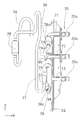
- FIG. 7 shows a state in which the muffler 36 and the surrounding structure are viewed from the front
- FIG. 8 shows a state in which the muffler 36 and the surrounding structure are viewed from the right side.
- the gas side shut-off valve 35 is fixed to the right side plate 52
- the muffler 36 is also arranged and fixed so as to extend straight in the plane of the plane (YZ plane) extending substantially in the front-rear and up-down directions.
- the gas side shut-off valve 35 is attached to the right side plate 52, it is inclined both in the horizontal direction (Y-axis direction) and in the vertical direction (Z-axis direction).
- the inclination angle is, for example, 30 degrees or more with respect to the horizontal direction and the vertical direction, and is preferably set within a range of 45 degrees ⁇ 10 degrees with respect to the horizontal direction, for example.
- the three mufflers 36 When the three mufflers 36 are distinguished from each other, they are referred to as an upper muffler 36a, an intermediate muffler 36b, and a lower muffler 36c. Similarly, when distinguishing the three gas side closing valves 35 from each other, they are referred to as an upper gas side closing valve 35a, an intermediate gas side closing valve 35b, and a lower gas side closing valve 35c.
- the thermistors functioning as the three suction temperature sensors 94 corresponding to these are referred to as an upper thermistor 96, an intermediate thermistor 97, and a lower thermistor 98.
- the upper muffler 36a is provided between the upper gas side closing valve 35a and the refrigerant pipe 77, and reduces the pulsation of the refrigerant flowing through the upper gas side closing valve 35a.
- the intermediate muffler 36b is provided between the intermediate gas side closing valve 35b and the refrigerant pipe 77, and reduces the pulsation of the refrigerant flowing through the intermediate gas side closing valve 35a.
- the lower muffler 36c is provided between the lower gas side closing valve 35c and the refrigerant pipe 77, and reduces the pulsation of the refrigerant flowing through the lower gas side closing valve 35c.
- an upper muffler 36a, an intermediate muffler 36b, and a lower muffler 36c are arranged so as to extend substantially parallel to each other.
- the shapes of the mufflers 36a, 36b, 36c are cylindrical, more specifically cylindrical.
- the lengths of these mufflers 36a, 36b, 36c are, for example, 75 mm.
- the distance between the connection pipes 71, 72, 73 and the adjacent ones of the three connecting portions of the upper gas side closing valve 35a, the intermediate gas side closing valve 35b, and the lower gas side closing valve 35c is For example, it is set to 90 mm.
- the distance from the connection part of the gas side closing valve 35a and the connecting pipe 71 to the connection part of the gas side closing valve 35b and the connecting pipe 72 and the connecting part of the gas side closing valve 35b and the connecting pipe 72 to the gas side closing valve 35c The distance to the connection part of the connection pipe 73 is 120% of the muffler length, and is set to be less than 130% of the muffler length. Since the heat source unit 30 includes the common muffler 38, it is easy to use small-sized mufflers 36a, 36b, and 36c.
- the merger 37 merges the refrigerant flowing through the upper gas side closing valve 35a, the intermediate gas side closing valve 35b, and the lower gas side closing valve 35c, and flows the merged gas refrigerant through the refrigerant pipe 77.
- the connection pipe 74 connected to the merger 37 and the upper muffler 36a has a straight pipe portion 74a.
- An upper thermistor 96 is attached to the straight piping portion 74a.
- the connection piping 75 connected to the merger 37 and the intermediate muffler 36b has a straight piping portion 75a.
- An intermediate thermistor 97 is attached to the straight piping portion 75a.
- the connection pipe 76 connected to the merger 37 and the lower muffler 36c has a straight pipe portion 76a.
- An intermediate thermistor 98 is attached to the straight piping portion 76a.
- the straight piping portions 74a, 75a, and 76a are portions that extend linearly in the connecting piping 74, 75, and 76.
- the lengths of the straight pipe portions 74a, 75a, and 76a are 20 mm or more, and in the heat source unit 30, for example, they are set to 25 mm to 30 mm.
- connection pipes 74, 75, and 76 are connected to the merger 37 so that the refrigerant flows along the vertical direction from the top to the bottom.
- the merger 37 is also connected to the refrigerant pipe 77 so that the refrigerant flows along the vertical direction from top to bottom.
- the intermediate connection pipe 75 has two U-turn parts 75b and 75c in order to obtain the straight pipe part 75a. Such two U-turn portions 75b and 75c are useful for reducing the piping space.
- a muffler 38 is connected to refrigerant pipes 77 and 78 between the merger 37 and the accumulator 39.
- the gas refrigerant flowing from the upper gas side closing valve 35a, the intermediate gas side closing valve 35b, and the lower gas side closing valve 35c flows.
- the muffler 38 reduces the pulsation of the refrigerant flowing through these common refrigerant pipes 77 and 78.
- the refrigerant passes through the muffler 38 and flows into the accumulator 39.
- the distance L1 (see FIG. 4) from the connection portion between the upper gas side shut-off valve 35a and the connection pipe 71 to the front plate 51 of the casing 50 is less than 250% of the muffler length of the mufflers 36a, 36b, 36c, for example.
- the distance L1 is preferably set to 150 mm or less, that is, 200% or less of the muffler length.
- connection part between the upper gas side shut-off valve 35a and the connection pipe 71 is the first connection part
- connection part between the intermediate gas side shut-off valve 35b and the connection pipe 72 is the second connection part
- a connection portion between the gas side shut-off valve 35c on the side and the connection pipe 73 is a third connection portion.
- the communication pipe 13 connected to the upper gas side shut-off valve 35 a among the three communication pipes 13 is the first communication pipe
- the communication pipe 13 of the three utilization units 20 is connected via this communication pipe 13. What is connected to the gas-side closing valve 35a is the first usage unit.
- the communication pipe 13 connected to the intermediate gas side closing valve 35b is the second connection pipe
- the usage unit 20 connected to the gas side closing valve 35b via the communication pipe 13 is the second usage unit. Accordingly, in this case, the upper muffler 36a becomes the first muffler, and the middle muffler 36b becomes the second muffler.
- the occupied area in the vertical direction of the mufflers 36a and 36b is The refrigerant flow direction is shorter than when the refrigerant flow direction is the vertical direction, or the horizontal occupied area of the mufflers 36a and 36b is shorter than when the refrigerant flow direction is the horizontal direction.
- the sizes of the first and second mufflers 36a and 36b which are tubular and flow in the direction along the central axis, tend to be longer in the refrigerant flow direction.
- the refrigerant flow direction is inclined both in the vertical direction and in the horizontal direction, so that the occupied areas of the plurality of mufflers 36a and 36b are prevented from increasing in the vertical direction and the horizontal direction. Therefore, the installation space of the plurality of mufflers 36a and 36b can be reduced while obtaining high silence.
- the first straight pipe is connected to the connecting pipe 74 which is the first connecting pipe connected to the junction 37 and the muffler 36a which is the first muffler.
- the straight piping part 74a which is the second straight piping part is provided to the connecting pipe 75 which is the second connecting pipe connected to the merger 37 and the muffler 36b which is the second muffler. Is provided.
- the connecting pipes 74 and 75 are three-dimensionally piped in a small space so that the straight pipe parts 74a and 75a can be accommodated in the small pipe space, the first thermistor and the second thermistor are straightened while suppressing the expansion of the pipe space. It can attach to a 1st straight piping part and 2nd straight piping part of a shape.
- the muffler 36c can be regarded as the third muffler.
- the communication pipe 13 connected to the lower gas side closing valve 35c is the third connection pipe
- the usage unit 20 connected to the gas side closing valve 35c via it is the third usage unit. is there. Since the refrigerant flow direction in the muffler 36c, which is the third muffler, is inclined along the refrigerant flow direction in the first muffler and the second muffler, the refrigerant flow direction is vertical in the vertical occupied areas of the mufflers 36a, 36b, 36c.
- the three mufflers 36a, 36b, 36c are provided. Miniaturization of the heat source unit 30 with good quietness can be realized.
- the first muffler, the second muffler, and the third muffler 36a, 36b, 36c are arranged to be inclined, and the distance between the first connection portion and the second connection portion and the distance between the second connection portion and the third connection portion.
- the length to the connection part of the connection pipe 72 of the side closing valve 35c can be shortened. With such a configuration, it is possible to reduce the size of the heat source unit 30 including the mufflers 36a, 36b, and 36c, which is excellent in quietness, in particular, the length in the vertical direction of the connection portion with the connection pipe 13.
- the compressor 31 includes a connecting portion between the gas side closing valve 35a and the connecting pipe 71 as the first connecting portion and a connecting portion between the gas side closing valve 35b and the connecting pipe 72 as the second connecting portion to the common refrigerant pipes 77 and 78. Since the gas pipe returns to (2), it is not necessary to consider the problem such as the drift of the refrigerant, so that the restrictions imposed on the pipes from the gas side shutoff valves 35a, 35b to the common refrigerant pipe 77 are reduced. As a result, in the heat source unit 30, the degree of freedom of piping is increased and it is easy to reduce the piping space.
Landscapes
- Engineering & Computer Science (AREA)
- Mechanical Engineering (AREA)
- General Engineering & Computer Science (AREA)
- Physics & Mathematics (AREA)
- Thermal Sciences (AREA)
- Chemical & Material Sciences (AREA)
- Combustion & Propulsion (AREA)
- Other Air-Conditioning Systems (AREA)
Abstract
静粛性の良好な冷凍装置の熱源ユニットを小型化する。第1マフラであるマフラ(36a)は、第1接続部であるガス側閉鎖弁(35a)と接続管(71)の接続部から冷媒配管(77)までの間に設けられ、第1接続部を流れる冷媒の脈動を低減する。第2マフラであるマフラ(36b)は、第2接続部であるガス側閉鎖弁(35b)と接続管(72)の接続部から冷媒配管(77)までの間に設けられ、第2接続部を流れる冷媒の脈動を低減する。マフラ(36a,36b)は、マフラ(36a,36b)における冷媒流れ方向が鉛直方向に対しても水平方向に対しても傾斜している。
Description
本開示は、冷凍装置の熱源ユニットに関する。
従来から、マルチタイプの空気調和機の室外機において、複数のマフラを備えるものが知られている。例えば、特許文献1(実開平1-153425号公報)には、ガス管ヘッダにマフラを直接接続するものが開示されている。
しかしながら、特許文献1に記載されている室外機においては、ガス管ヘッダからマフラが水平方向に延びているため、マフラを設置するためのマフラ設置スペースがマフラの延びる方向に長く延びてしまって、マフラ設置スペースが大きくなる。また、マルチタイプの空気調和機の室外機では、接続可能な室内機の数に合わせてマフラの数が多くなるので、室外機が大型化する傾向がある。
本開示の課題は、静粛性の良好な冷凍装置の熱源ユニットを小型化することである。
本開示の第1観点に係る冷凍装置の熱源ユニットは、第1利用ユニット及び第2利用ユニットを含む複数の利用ユニットが第1連絡配管及び第2連絡配管を含む複数の連絡配管を介して接続される冷凍装置の熱源ユニットであって、第1利用ユニットと接続される第1連絡配管の接続先である第1接続部と、第2利用ユニットと接続される第2連絡配管の接続先である第2接続部と、第1接続部を流れる冷媒及び第2接続部を流れる冷媒が共に流れる共通の冷媒配管と、第1接続部から冷媒配管までの間に設けられ、第1接続部を流れる冷媒の脈動を低減する第1マフラと、第2接続部から冷媒配管までの間に設けられ、第2接続部を流れる冷媒の脈動を低減する第2マフラとを備え、第1マフラ及び第2マフラは、第1マフラ及び第2マフラにおける冷媒流れ方向が鉛直方向に対しても水平方向に対しても傾斜している。
第1観点に係る熱源ユニットによれば、第1マフラ及び第2マフラにおける冷媒の流れ方向が鉛直方向に対しても水平方向に対しても傾斜しているから、第1マフラ及び第2マフラの鉛直方向の占有領域は冷媒流れ方向が鉛直方向である場合に比べて短くなり、あるいは第1マフラ及び第2マフラの水平方向の占有領域は冷媒流れ方向が水平方向である場合に比べて短くなる。
本開示の第2観点に係る冷凍装置の熱源ユニットは、第1観点の熱源ユニットにおいて、第1マフラ及び第2マフラは、いずれも、筒状であって中心軸に沿う方向に冷媒が流れる、ものである。
第2観点に係る熱源ユニットによれば、筒状であって中心軸に沿う方向に冷媒が流れる第1マフラ及び第2マフラの大きさが冷媒流れ方向に長くなる傾向があるが、第1マフラ及び第2マフラについて冷媒流れ方向が鉛直方向に対しても水平方向に対しても傾斜することでこれら複数マフラの占有領域が鉛直方向及び水平方向において大きくなるのを抑制できる。
本開示の第3観点に係る冷凍装置の熱源ユニットは、第1観点または第2観点の熱源ユニットにおいて、共通の冷媒配管に接続され、第1接続部を流れる冷媒及び第2接続部を流れる冷媒を合流させる合流器と、合流器と第1マフラとに接続され、第1直線配管部を有する第1接続配管と、合流器と第2マフラとに接続され、第2直線配管部を有する第2接続配管と、第1直線配管部に取り付けられている第1サーミスタと、第2直線配管部に取り付けられている第2サーミスタと
をさらに備える、ものである。
をさらに備える、ものである。
第3観点に係る熱源ユニットによれば、合流器と第1マフラとに接続されている第1接続配管及び合流器と第2マフラとに接続されている第2接続配管に第1直線配管部及び第2直線配管部が設けられているから、第1接続配管及び第2接続配管を小さなスペースで立体的に配管して第1直線配管部及び第2直線配管部を小さな配管スペースの中に収めることができる。
本開示の第4観点に係る冷凍装置の熱源ユニットは、第3観点の熱源ユニットにおいて、第1直線配管部及び第2直線配管部は、いずれも、長さが20mm以上である、ものである。
第4観点に係る熱源ユニットによれば、長さが20mm以上の第1直線配管部及び第2直線配管部に第1サーミスタ及び第2サーミスタが取り付けられることから、各利用ユニットから戻ってくるガス冷媒の温度を熱源ユニットの方で安定して検出することができる。
本開示の第5観点に係る冷凍装置の熱源ユニットは、第1観点から第4観点のいずれかの熱源ユニットにおいて、第1利用ユニット及び第2利用ユニットとは異なる第3利用ユニットと接続される第3連絡配管の接続先である第3接続部と、第3接続部から冷媒配管までの間に設けられ、第3接続部を流れる冷媒の脈動を低減する第3マフラとをさらに備え、第3マフラは、第3マフラにおける冷媒流れ方向が第1マフラ及び第2マフラにおける冷媒流れ方向に沿って傾斜している、ものである。
第5観点に係る熱源ユニットによれば、第3マフラにおける冷媒流れ方向が第1マフラ及び第2マフラにおける冷媒流れ方向に沿って傾斜しているから、第1マフラ乃至第3マフラの鉛直方向の占有領域は冷媒流れ方向が鉛直方向である場合に比べて短くなり、あるいは第1マフラ乃至第3マフラの水平方向の占有領域は冷媒流れ方向が水平方向である場合に比べて短くなる。
本開示の第6観点に係る冷凍装置の熱源ユニットは、第5観点の熱源ユニットにおいて、第1接続部、第2接続部及び第3接続部が順に配置され、第1接続部と第2接続部の距離が第1マフラ及び第2マフラのうちの短い方のマフラ長の130%未満であり、第2接続部と第3接続部の距離が第2マフラ及び第3マフラのうちの短い方のマフラ長の130%未満である、ものである。
第6観点に係る熱源ユニットによれば、第1マフラ、第2マフラ及び第3マフラが傾斜して配置されていて第1接続部と第2接続部の距離及び第2接続部と第3接続部の距離がそれぞれ短い方のマフラ長の130%未満で配置できていることから、第1接続部から第3接続部までの長さを短くできる。
本開示の第7観点に係る冷凍装置の熱源ユニットは、第1観点から第6観点のいずれかの熱源ユニットにおいて、上面視において第1接続部及び第2接続部から第1マフラ及び第2マフラが延びる方向のマフラ長の250%未満の距離に配置されている前板を有し、共通の冷媒配管と第1マフラと第2マフラとを収納しているケーシングをさらに備える、ものである。
第7観点に係る熱源ユニットによれば、第1接続部及び第2接続部からマフラ長の250%未満の距離に前板が配置されていることから、熱源ユニットの前後方向の長さを短くできる。
本開示の第8観点に係る冷凍装置の熱源ユニットは、第1観点から第7観点のいずれかの熱源ユニットにおいて、共通の冷媒配管を流れる冷媒を吸入する圧縮機をさらに備え、第1接続部及び第2接続部から冷媒配管までが圧縮機に戻るガス管である、ものである。
第8観点に係る熱源ユニットによれば、第1接続部及び第2接続部から共通の冷媒配管までが圧縮機に戻るガス管であることから、冷媒の偏流などの問題を考慮しなくても済むので、第1接続部及び第2接続部から共通の冷媒配管までの配管に課される制約が少なくなる。
本開示の第1観点、第5観点または第6観点に係る冷凍装置の熱源ユニットでは、静粛性の良好な熱源ユニットの小型化ができる。
本開示の第2観点に係る冷凍装置の熱源ユニットでは、高い静粛性を得ながら複数マフラの設置スペースを小さくすることができる。
本開示の第3観点に係る冷凍装置の熱源ユニットでは、配管スペースの拡大を抑えながら第1サーミスタ及び第2サーミスタを取り付けるスペースを設けることができる。
本開示の第4観点に係る冷凍装置の熱源ユニットでは、配管スペースの増大を抑えながら精度の良いガス冷媒の温度検出を実現できる。
本開示の第7観点に係る冷凍装置の熱源ユニットでは、熱源ユニットの大幅な小型化を実現することができる。
本開示の第8観点に係る冷凍装置の熱源ユニットでは、配管の取り回しの自由度が高くなって配管スペースを削減することが容易になる。
(1)全体構成
図1に示されている冷凍装置10は、複数の利用ユニット20と、利用ユニット20に接続された熱源ユニット30とを備えている。ここでは3台の利用ユニット20が示されているが、本開示が適用できる利用ユニット20の台数は3台に限定されるものではない。利用ユニット20と熱源ユニット30とは連絡配管12,13で接続されており、並列に接続された複数の利用ユニット20と熱源ユニット30の間で冷媒を循環させるための冷媒回路11が形成されている。この冷媒回路11を冷媒が循環することによって、冷凍装置10は、蒸気圧縮式冷凍サイクルを行うことができる。
図1に示されている冷凍装置10は、複数の利用ユニット20と、利用ユニット20に接続された熱源ユニット30とを備えている。ここでは3台の利用ユニット20が示されているが、本開示が適用できる利用ユニット20の台数は3台に限定されるものではない。利用ユニット20と熱源ユニット30とは連絡配管12,13で接続されており、並列に接続された複数の利用ユニット20と熱源ユニット30の間で冷媒を循環させるための冷媒回路11が形成されている。この冷媒回路11を冷媒が循環することによって、冷凍装置10は、蒸気圧縮式冷凍サイクルを行うことができる。
さらに詳細に見ると、各利用ユニット20は、利用側熱交換器21を備えている。また、熱源ユニット30は、圧縮機31と熱源側熱交換器32と複数の膨張弁33と液側閉鎖弁34とガス側閉鎖弁35とマフラ36と合流器37とマフラ38とアキュムレータ39とを備えている。この熱源ユニット30では、膨張弁33、液側閉鎖弁34、ガス側閉鎖弁35、閉鎖弁側のマフラ36はそれぞれ3個ずつであり、利用ユニット20と同数である。膨張弁33には例えば電動弁を用いることができる。
圧縮機31、熱源側熱交換器32、膨張弁33、液側閉鎖弁34、利用側熱交換器21、ガス側閉鎖弁35、閉鎖弁側のマフラ36、合流器37、共通のマフラ38及びアキュムレータ39の順に冷媒が循環するように冷媒回路11が構成されている。圧縮機31は、アキュムレータ39から吸入したガス冷媒を圧縮する。圧縮機31の吐出口から出た高温高圧の冷媒は、熱源側熱交換器32の流入口に流入する。熱源側熱交換器32において室外空気との間で熱交換された冷媒は、熱源側熱交換器32の流出口から流出し、膨張弁33の流入口に流入する。膨張弁33で膨張されて減圧された冷媒は、膨張弁33の流出口から流出し、液側閉鎖弁34及び連絡配管12を介して、利用側熱交換器21の流入口に流入する。利用側熱交換器21において室内空気との間で熱交換されたガス冷媒は、利用側熱交換器21の流出口から流出し、連絡配管13、ガス側閉鎖弁35、閉鎖弁側のマフラ36、合流器37、共通のマフラ38及びアキュムレータ39を介して圧縮機31の吸入口に流入する。
なお、ここで冷凍装置とは、図1に示されている空気調和装置のように、圧縮機31で動力を消費し、熱源側熱交換器32と利用側熱交換器21のうちの一方から熱を取り入れ、他方から熱を排出する装置である。換言すると、冷凍装置は、冷媒回路で冷凍サイクルを行う装置である。冷凍装置には、空気調和装置以外に、例えば、湯を供給するヒートポンプ式給湯器、冷蔵庫及び庫内を冷却する冷却装置が含まれる。
(2)詳細構成
(2-1)利用ユニット
各利用ユニット20のケーシング29の内部には、利用側熱交換器21と利用側ファン22とが設置されている。利用側熱交換器21は、空気と冷媒との間の熱交換をさせる空気熱交換器であって、例えば伝熱管と多数のフィンとにより構成されたクロスフィン式のフィン・アンド・チューブ型熱交換器である。利用側熱交換器21においては、チューブ(伝熱管)内を流れる冷媒回路11の冷媒と、フィンの間を通過する室内空気との間で熱交換が行われる。従って、利用側熱交換器21は、冷房運転時に冷媒の蒸発器として機能して室内空気を冷却する。利用ユニット20の利用側ファン22は、ケーシング29内に室内空気を吸入して、利用側熱交換器21において冷媒と熱交換させた後に、熱交換後の空気を供給空気として室内に供給する送風機として機能する。
(2-1)利用ユニット
各利用ユニット20のケーシング29の内部には、利用側熱交換器21と利用側ファン22とが設置されている。利用側熱交換器21は、空気と冷媒との間の熱交換をさせる空気熱交換器であって、例えば伝熱管と多数のフィンとにより構成されたクロスフィン式のフィン・アンド・チューブ型熱交換器である。利用側熱交換器21においては、チューブ(伝熱管)内を流れる冷媒回路11の冷媒と、フィンの間を通過する室内空気との間で熱交換が行われる。従って、利用側熱交換器21は、冷房運転時に冷媒の蒸発器として機能して室内空気を冷却する。利用ユニット20の利用側ファン22は、ケーシング29内に室内空気を吸入して、利用側熱交換器21において冷媒と熱交換させた後に、熱交換後の空気を供給空気として室内に供給する送風機として機能する。
(2-2)熱源ユニット30
(2-2-1)熱源ユニット30の構成の概要
熱源ユニット30はケーシング50を備え、そのケーシング50の中に、圧縮機31と熱源側熱交換器32と複数の膨張弁33と複数の液側閉鎖弁34と複数のガス側閉鎖弁35と複数のマフラ36と合流器37とマフラ38とアキュムレータ39と熱源側ファン40と電装品箱41と吐出温度センサ91と室外温度センサ92と熱源側熱交換器用温度センサ93と吸入温度センサ94とが設置されている。熱源ユニット30に設けられている圧縮機31は、回転数(運転周波数)によって運転容量を変えることが可能な容積式圧縮機であり、例えばインバータにより回転数が制御されるモータ(図示せず)によって圧縮機31の回転数が制御される。熱源側ファン40は、熱源ユニット30のケーシング50の周りの外気を熱源側熱交換器32に送る。熱源側ファン40は、熱源側熱交換器32に供給する空気の風量を変更することが可能なファンであり、モータ(図示せず)によって駆動されるプロペラファン等である。圧縮機31、膨張弁33及び熱源側ファン40の動作制御は、電装品箱41の中に収納されている熱源側制御装置によって行われる。
(2-2-1)熱源ユニット30の構成の概要
熱源ユニット30はケーシング50を備え、そのケーシング50の中に、圧縮機31と熱源側熱交換器32と複数の膨張弁33と複数の液側閉鎖弁34と複数のガス側閉鎖弁35と複数のマフラ36と合流器37とマフラ38とアキュムレータ39と熱源側ファン40と電装品箱41と吐出温度センサ91と室外温度センサ92と熱源側熱交換器用温度センサ93と吸入温度センサ94とが設置されている。熱源ユニット30に設けられている圧縮機31は、回転数(運転周波数)によって運転容量を変えることが可能な容積式圧縮機であり、例えばインバータにより回転数が制御されるモータ(図示せず)によって圧縮機31の回転数が制御される。熱源側ファン40は、熱源ユニット30のケーシング50の周りの外気を熱源側熱交換器32に送る。熱源側ファン40は、熱源側熱交換器32に供給する空気の風量を変更することが可能なファンであり、モータ(図示せず)によって駆動されるプロペラファン等である。圧縮機31、膨張弁33及び熱源側ファン40の動作制御は、電装品箱41の中に収納されている熱源側制御装置によって行われる。
熱源側熱交換器32では、熱源ユニット30の内部に流入する外気と圧縮機31で圧縮された冷媒との間で熱交換が行われる。熱源側熱交換器32は、例えばクロスフィン式のフィン・アンド・チューブ型熱交換器であり、チューブ(伝熱管)の中を通る冷媒と多数のフィンの間を通過する外気との間の熱交換を行う。つまり、熱源側熱交換器32は、冷房運転時に放熱器として機能している。この熱源側熱交換器32を通る間に冷媒から熱が放出されて、ガス冷媒は、気液二相状態を経て液冷媒に変化する。熱源側熱交換器32で熱交換された空気は、熱源ユニット30の外部に吹き出される。
吐出温度センサ91は、例えば圧縮機31の吐出管に取り付けられ、圧縮機31から吐出される冷媒の温度を検出する。室外温度センサ92は、熱源側ファン40が熱源ユニット30のケーシング50内に取り入れる室外空気の雰囲気温度を検知する。熱源側熱交換器用温度センサ93は、熱源側熱交換器32の中の気液二相状態になっている部分の温度を検知する。各吸入温度センサ94は、対応する利用ユニット20から戻ってきたガス冷媒の温度を検知する。冷凍装置10は、これら吐出温度センサ91、室外温度センサ92、熱源側熱交換器用温度センサ93及び吸入温度センサ94の検出結果に応じて冷媒回路11を流れる冷媒の状態を制御している。これら吐出温度センサ91、室外温度センサ92、熱源側熱交換器用温度センサ93及び吸入温度センサ94には、例えばサーミスタを用いることができる。
(2-2-2)熱源ユニット30の構造の概要
図2には、本開示の実施形態に係る、天板などを取り外した状態の熱源ユニット30を、上方から見た熱源ユニットの内部の様子が示されている。図2に示されている熱源ユニット30を正面から見たときの熱源ユニットの外観が図3に示されている。なお、図2においては、天板及び安全を確保するためにユニット前面に設けられるグリッドなどが取り外された状態が示されている。
図2には、本開示の実施形態に係る、天板などを取り外した状態の熱源ユニット30を、上方から見た熱源ユニットの内部の様子が示されている。図2に示されている熱源ユニット30を正面から見たときの熱源ユニットの外観が図3に示されている。なお、図2においては、天板及び安全を確保するためにユニット前面に設けられるグリッドなどが取り外された状態が示されている。
熱源ユニット30は、鉛直方向に延びるZ軸に沿った辺と、前後方向に延びるY軸に沿った辺と、左右方向に延びるX軸方向に沿った辺を持つ直方体形状を基礎とした外観を呈するケーシング50を備えている。図1には示されていないが、左右(X軸方向)に長く、前後(Y軸方向)に短い長方形状の金属板の周囲を下方に折り曲げた天板がケーシング50の天面に位置する。また、ケーシング50の他の5面にも金属板が配されている。ユニット前面に配置されているケーシング50の前板51の中央部分には、円形の開口部21aが形成されている。ユニット右側面に配置されているケーシング50の右側板52には、利用ユニット20に接続して冷媒を循環させるための接続部52aが設けられている。右側板52は、実質的に直角に曲げられており、ユニット後面側の一部も覆っている。そして、ユニット後面には、大きな長方形状の開口部53が形成されている。また、ユニット左側面に配置されているケーシング50の左側板54にも熱源ユニット30の内部に空気を吸い込むための開口部(図示せず)が形成されている。ケーシング50の底は、金属製の底フレーム55で覆われている。
熱源側熱交換器32は、ユニット後面からユニット左側面にかけて配置されている。ユニット後面側の開口部53及び左側板54の開口部を通って熱源ユニット30の外部から内部に吸い込まれる空気が、この熱源側熱交換器32を通過する。熱源側熱交換器32を通過する気流は、熱源側ファン40によって発生する。
(2-2-3)機械室58の構造の概要
図4には、図2の状態の熱源ユニット30からさらに電装品箱41、前板51及び右側板52などを取り外して上から見た状態が示されている。図5及び図6には、図4の熱源ユニット30を右斜め上から見た状態及び真正面から見た状態が示されている。
図4には、図2の状態の熱源ユニット30からさらに電装品箱41、前板51及び右側板52などを取り外して上から見た状態が示されている。図5及び図6には、図4の熱源ユニット30を右斜め上から見た状態及び真正面から見た状態が示されている。
上述の熱源側ファン40と熱源側熱交換器32は、図4に示されているように、仕切板56で仕切られた送風機室57に配置されている。仕切板56を挟んで送風機室57の反対側には機械室58が設けられている。高い冷房能力を得るには、熱源側熱交換器32において単位時間当たりに多くの冷媒と多くの空気との間で熱交換を行わせることが好ましいので、熱交換のためのスペースを確保するため、機械室58に比べて送風機室57が大きくなる。送風機室57に対して、空気が流れる熱交換のためのスペースを確保する必要の無い機械室58では、できる限り隙間を小さくするように機器が配置される。機械室58には、圧縮機31と、複数の膨張弁33と、複数のマフラ36と、合流器37と、マフラ38と、アキュムレータ39と、電装品箱41の大部分とが位置する。この機械室58では、圧縮機31、アキュムレータ39及び電装品箱41などが占有する領域を除いた配管スペースを使って接続配管が行われる。圧縮機31及びアキュムレータ39などの大きさは熱源ユニット30の性能及び価格などに応じて実質的に決まってしまうので、配管スペースを小さくすることが熱源ユニット30の小型化には有効である。
(2-2-4)マフラ36の配置とマフラ36の周辺の構造
配管スペースでは、3つのガス側閉鎖弁35から3つの閉鎖弁側のマフラ36まで延びる3本の接続管71,72,73と3つのマフラ36から1つの合流器37まで延びる3本の接続配管74,75,76によって、ガス側閉鎖弁35から合流器37までの接続が行われている。合流器37と共通のマフラ38が冷媒配管77によって接続され、マフラ38とアキュムレータ39が冷媒配管78によって接続されている。
配管スペースでは、3つのガス側閉鎖弁35から3つの閉鎖弁側のマフラ36まで延びる3本の接続管71,72,73と3つのマフラ36から1つの合流器37まで延びる3本の接続配管74,75,76によって、ガス側閉鎖弁35から合流器37までの接続が行われている。合流器37と共通のマフラ38が冷媒配管77によって接続され、マフラ38とアキュムレータ39が冷媒配管78によって接続されている。
接続管71,72,73には、例えば中央付近で実質的に直角に曲げられた同じ形状の銅管が用いられる。接続管71,72,73は、例えばガス側閉鎖弁35から実質的に左右方向(X軸方向)に延びるようにガス側閉鎖弁35に接続され、固定されている。閉鎖弁側のマフラ36は、接続管71,72,73から、実質的に真っ直ぐに延びるように接続されている。例えば、1つのガス側閉鎖弁35と3本の接続管71,72,73のうちの1つと1つのマフラ36とが接続されて一体化され、1つの入口部品として準備されている。
図7には、マフラ36及びその周囲の構造を真正面から見た状態が示されており、図8には、マフラ36及びその周囲の構造を右側面から見た状態が示されている。ガス側閉鎖弁35が右側板52に固定されると、マフラ36も、実質的に前後上下に延びる平面(YZ平面)の面内で真っ直ぐに延びるように配置されて固定される。そして、ガス側閉鎖弁35が右側板52に取り付けられた状態で、水平方向(Y軸方向)に対しても、鉛直方向(Z軸方向)に対しても傾斜している。傾斜する角度は、例えば、水平方向に対しても鉛直方向に対しても30度以上傾けられ、好ましくは例えば水平方向に対して45度±10度の範囲に設定される。
3つのマフラ36をそれぞれに区別するときには、上側のマフラ36a、中間のマフラ36b及び下側のマフラ36cと呼ぶ。同様に、3つのガス側閉鎖弁35をそれぞれに区別するときには、上側のガス側閉鎖弁35a、中間のガス側閉鎖弁35b及び下側のガス側閉鎖弁35cと呼ぶ。また、これらに対応する3つの吸入温度センサ94として機能するサーミスタを、上側のサーミスタ96、中間のサーミスタ97及び下側のサーミスタ98と呼ぶ。上側のマフラ36aは、上側のガス側閉鎖弁35aから冷媒配管77までの間に設けられ、上側のガス側閉鎖弁35aを流れる冷媒の脈動を低減する。中間のマフラ36bは、中間のガス側閉鎖弁35bから冷媒配管77までの間に設けられ、中間のガス側閉鎖弁35aを流れる冷媒の脈動を低減する。下側のマフラ36cは、下側のガス側閉鎖弁35cから冷媒配管77までの間に設けられ、下側のガス側閉鎖弁35cを流れる冷媒の脈動を低減する。この熱源ユニット30においては、上側のマフラ36a、中間のマフラ36b及び下側のマフラ36cが実質的に互いに平行に延びるように配置されている。
マフラ36a,36b,36cの形状は筒状、さらに詳しくは円筒状である。これらマフラ36a,36b,36cの長さは、例えば75mmである。それに対して、接続管71,72,73と上側のガス側閉鎖弁35a、中間のガス側閉鎖弁35b及び下側のガス側閉鎖弁35cの3つの接続部の互いに隣接するものの間の距離は例えば90mmに設定されている。つまり、ガス側閉鎖弁35aと接続管71の接続部からガス側閉鎖弁35bと接続管72の接続部までの距離及びガス側閉鎖弁35bと接続管72の接続部からガス側閉鎖弁35cと接続管73の接続部までの距離は、マフラ長の120%であり、マフラ長の130%未満に設定されている。なお、熱源ユニット30は、共通のマフラ38を備えていることから、個別のマフラ36a,36b,36cに小型のものを用い易くなっている。
合流器37は、上側のガス側閉鎖弁35a、中間のガス側閉鎖弁35b及び下側のガス側閉鎖弁35cに流れる冷媒を合流させて、合流したガス冷媒を冷媒配管77に流す。この合流器37と上側のマフラ36aとに接続されている接続配管74は、直線配管部74aを有している。この直線配管部74aに上側のサーミスタ96が取り付けられている。合流器37と中間のマフラ36bとに接続されている接続配管75は、直線配管部75aを有している。この直線配管部75aに中間のサーミスタ97が取り付けられている。また、合流器37と下側のマフラ36cとに接続されている接続配管76は、直線配管部76aを有している。この直線配管部76aに中間のサーミスタ98が取り付けられている。直線配管部74a,75a,76aは、接続配管74,75,76において直線状に延びている部分である。これら直線配管部74a,75a,76aの長さは、20mm以上であり、この熱源ユニット30においては例えば25mm~30mmに設定されている。
接続配管74,75,76は、上から下に向って鉛直方向に沿って冷媒が流れるように、合流器37に接続されている。また、合流器37も、上から下に向って鉛直方向に沿って冷媒が流れるように、冷媒配管77に接続されている。このような接続状態において、中間の接続配管75は、直線配管部75aを得るために、2つのUターン部75b,75cを有している。このような2つのUターン部75b,75cは、配管スペースを小さくするのに役立っている。
合流器37とアキュムレータ39との間の冷媒配管77,78にマフラ38が接続されている。共通の冷媒配管77,78は、上側のガス側閉鎖弁35a、中間のガス側閉鎖弁35b及び下側のガス側閉鎖弁35cから流入したガス冷媒が流れる。マフラ38は、これら共通の冷媒配管77,78に流れる冷媒の脈動を低減する。冷媒はマフラ38を通過してアキュムレータ39に流入する。
上面視において、上側のガス側閉鎖弁35aと接続管71の接続部からケーシング50の前板51までの距離L1(図4参照)は、例えばマフラ36a,36b,36cのマフラ長の250%未満になるように構成でき、例えば距離L1が150mm以下つまりマフラ長の200%以下に設定されることが好ましい。
(3)変形例
(3-1)変形例1A
上記実施形態では、冷房専用の熱源ユニット30に本開示を適用する場合について説明したが、本開示は、暖房を行うマルチタイプの熱源ユニットに適用することもできる。
(3-1)変形例1A
上記実施形態では、冷房専用の熱源ユニット30に本開示を適用する場合について説明したが、本開示は、暖房を行うマルチタイプの熱源ユニットに適用することもできる。
(4)特徴
(4-1)
上述の熱源ユニット30では、例えば、上側のガス側閉鎖弁35aと接続管71の接続部が第1接続部、中間のガス側閉鎖弁35bと接続管72の接続部が第2接続部、下側のガス側閉鎖弁35cと接続管73の接続部が第3接続部である。この場合、3本の連絡配管13のうち上側のガス側閉鎖弁35aに接続している連絡配管13が第1連絡配管であり、3台の利用ユニット20のうちのこの連絡配管13を介してガス側閉鎖弁35aに接続しているものが第1利用ユニットである。また、中間のガス側閉鎖弁35bに接続している連絡配管13が第2連絡配管であり、それを介してガス側閉鎖弁35bに接続している利用ユニット20が第2利用ユニットである。従って、この場合には、上側のマフラ36aが第1マフラになり、中間のマフラ36bが第2マフラになる。これら、第1マフラ及び第2マフラであるマフラ36a,36bにおける冷媒の流れ方向が鉛直方向に対しても水平方向に対しても傾斜しているから、マフラ36a,36bの鉛直方向の占有領域は冷媒流れ方向が鉛直方向である場合に比べて短くなり、あるいはマフラ36a,36bの水平方向の占有領域は冷媒流れ方向が水平方向である場合に比べて短くなる。このような構成によって、マフラ36a,36bを備える静粛性の良好な熱源ユニット30の小型化が実現できる。
(4-1)
上述の熱源ユニット30では、例えば、上側のガス側閉鎖弁35aと接続管71の接続部が第1接続部、中間のガス側閉鎖弁35bと接続管72の接続部が第2接続部、下側のガス側閉鎖弁35cと接続管73の接続部が第3接続部である。この場合、3本の連絡配管13のうち上側のガス側閉鎖弁35aに接続している連絡配管13が第1連絡配管であり、3台の利用ユニット20のうちのこの連絡配管13を介してガス側閉鎖弁35aに接続しているものが第1利用ユニットである。また、中間のガス側閉鎖弁35bに接続している連絡配管13が第2連絡配管であり、それを介してガス側閉鎖弁35bに接続している利用ユニット20が第2利用ユニットである。従って、この場合には、上側のマフラ36aが第1マフラになり、中間のマフラ36bが第2マフラになる。これら、第1マフラ及び第2マフラであるマフラ36a,36bにおける冷媒の流れ方向が鉛直方向に対しても水平方向に対しても傾斜しているから、マフラ36a,36bの鉛直方向の占有領域は冷媒流れ方向が鉛直方向である場合に比べて短くなり、あるいはマフラ36a,36bの水平方向の占有領域は冷媒流れ方向が水平方向である場合に比べて短くなる。このような構成によって、マフラ36a,36bを備える静粛性の良好な熱源ユニット30の小型化が実現できる。
(4-2)
筒状であって中心軸に沿う方向に冷媒が流れる第1マフラ及び第2マフラであるマフラ36a,36bの大きさは、冷媒流れ方向に長くなる傾向がある。しかし、マフラ36a,36bについて冷媒流れ方向が鉛直方向に対しても水平方向に対しても傾斜することで、これら複数のマフラ36a,36bの占有領域が鉛直方向及び水平方向において大きくなるのを抑制できるので、高い静粛性を得ながら複数マフラ36a,36bの設置スペースを小さくすることができている。
筒状であって中心軸に沿う方向に冷媒が流れる第1マフラ及び第2マフラであるマフラ36a,36bの大きさは、冷媒流れ方向に長くなる傾向がある。しかし、マフラ36a,36bについて冷媒流れ方向が鉛直方向に対しても水平方向に対しても傾斜することで、これら複数のマフラ36a,36bの占有領域が鉛直方向及び水平方向において大きくなるのを抑制できるので、高い静粛性を得ながら複数マフラ36a,36bの設置スペースを小さくすることができている。
(4-3)
第1サーミスタであるサーミスタ96と第2サーミスタであるサーミスタ97を設けるため、合流器37と第1マフラであるマフラ36aとに接続されている第1接続配管である接続配管74に第1直線配管部である直線配管部74aが設けられ、合流器37と第2マフラであるマフラ36bとに接続されている第2接続配管である接続配管75に第2直線配管部である直線配管部75aが設けられている。接続配管74,75を小さなスペースで立体的に配管して直線配管部74a,75aを小さな配管スペースの中に収めることができるので、配管スペースの拡大を抑えながら第1サーミスタ及び第2サーミスタを直線状の第1直線配管部及び第2直線配管部に取り付けることができる。
第1サーミスタであるサーミスタ96と第2サーミスタであるサーミスタ97を設けるため、合流器37と第1マフラであるマフラ36aとに接続されている第1接続配管である接続配管74に第1直線配管部である直線配管部74aが設けられ、合流器37と第2マフラであるマフラ36bとに接続されている第2接続配管である接続配管75に第2直線配管部である直線配管部75aが設けられている。接続配管74,75を小さなスペースで立体的に配管して直線配管部74a,75aを小さな配管スペースの中に収めることができるので、配管スペースの拡大を抑えながら第1サーミスタ及び第2サーミスタを直線状の第1直線配管部及び第2直線配管部に取り付けることができる。
(4-4)
長さが20mm以上の第1直線配管部及び第2直線配管部である直線配管部74a,75aに第1サーミスタ及び第2サーミスタであるサーミスタ96,97が取り付けられることから、各利用ユニット20から戻ってくるガス冷媒の温度を熱源ユニット30の方で安定して検出することができる。
長さが20mm以上の第1直線配管部及び第2直線配管部である直線配管部74a,75aに第1サーミスタ及び第2サーミスタであるサーミスタ96,97が取り付けられることから、各利用ユニット20から戻ってくるガス冷媒の温度を熱源ユニット30の方で安定して検出することができる。
(4-5)
上述のようにマフラ36a,36bを第1マフラ及び第2マフラとみなした場合には、マフラ36cを第3マフラとみなせる。この場合、下側のガス側閉鎖弁35cに接続している連絡配管13が第3連絡配管であり、それを介してガス側閉鎖弁35cに接続している利用ユニット20が第3利用ユニットである。第3マフラであるマフラ36cにおける冷媒流れ方向が第1マフラ及び第2マフラにおける冷媒流れ方向に沿って傾斜しているから、マフラ36a,36b,36cの鉛直方向の占有領域は冷媒流れ方向が鉛直方向である場合に比べて短くなり、あるいはマフラ36a,36b,36cの水平方向の占有領域は冷媒流れ方向が水平方向である場合に比べて短くなるので、3つのマフラ36a,36b,36cを備える静粛性の良好な熱源ユニット30の小型化が実現できる。
上述のようにマフラ36a,36bを第1マフラ及び第2マフラとみなした場合には、マフラ36cを第3マフラとみなせる。この場合、下側のガス側閉鎖弁35cに接続している連絡配管13が第3連絡配管であり、それを介してガス側閉鎖弁35cに接続している利用ユニット20が第3利用ユニットである。第3マフラであるマフラ36cにおける冷媒流れ方向が第1マフラ及び第2マフラにおける冷媒流れ方向に沿って傾斜しているから、マフラ36a,36b,36cの鉛直方向の占有領域は冷媒流れ方向が鉛直方向である場合に比べて短くなり、あるいはマフラ36a,36b,36cの水平方向の占有領域は冷媒流れ方向が水平方向である場合に比べて短くなるので、3つのマフラ36a,36b,36cを備える静粛性の良好な熱源ユニット30の小型化が実現できる。
(4-6)
第1マフラ、第2マフラ及び第3マフラであるマフラ36a,36b,36cが傾斜して配置されていて第1接続部と第2接続部の距離及び第2接続部と第3接続部の距離がそれぞれ短い方のマフラ長の130%未満で配置できているので、第1接続部である上側のガス側閉鎖弁35aと接続管71の接続部から、第3接続部である下側のガス側閉鎖弁35cの接続管72の接続部までの長さを短くできる。このような構成により、マフラ36a,36b,36cを備える静粛性の良好な熱源ユニット30の小型化、特に連絡配管13との接続部分の上下方向の長さを短くできる。
第1マフラ、第2マフラ及び第3マフラであるマフラ36a,36b,36cが傾斜して配置されていて第1接続部と第2接続部の距離及び第2接続部と第3接続部の距離がそれぞれ短い方のマフラ長の130%未満で配置できているので、第1接続部である上側のガス側閉鎖弁35aと接続管71の接続部から、第3接続部である下側のガス側閉鎖弁35cの接続管72の接続部までの長さを短くできる。このような構成により、マフラ36a,36b,36cを備える静粛性の良好な熱源ユニット30の小型化、特に連絡配管13との接続部分の上下方向の長さを短くできる。
(4-7)
熱源ユニット30においては、第1接続部であるガス側閉鎖弁35aと接続管71の接続部及び第2接続部であるガス側閉鎖弁35bと接続管72の接続部からマフラ長の250%未満の距離に前板51が配置されていることから、熱源ユニット30の前後方向の長さを短くでき、マフラ36a,36bを備える静粛性の良好な熱源ユニット30の大幅な小型化、特にケーシング50についての前後方向の長さの短縮が実現できる。
熱源ユニット30においては、第1接続部であるガス側閉鎖弁35aと接続管71の接続部及び第2接続部であるガス側閉鎖弁35bと接続管72の接続部からマフラ長の250%未満の距離に前板51が配置されていることから、熱源ユニット30の前後方向の長さを短くでき、マフラ36a,36bを備える静粛性の良好な熱源ユニット30の大幅な小型化、特にケーシング50についての前後方向の長さの短縮が実現できる。
(4-8)
第1接続部であるガス側閉鎖弁35aと接続管71の接続部及び第2接続部であるガス側閉鎖弁35bと接続管72の接続部から共通の冷媒配管77,78までが圧縮機31に戻るガス管であることから、冷媒の偏流などの問題を考慮しなくても済むので、ガス側閉鎖弁35a,35bから共通の冷媒配管77までの配管に課される制約が少なくなる。その結果、熱源ユニット30においては、配管の取り回しの自由度が高くなって配管スペースを削減することが容易になっている。
第1接続部であるガス側閉鎖弁35aと接続管71の接続部及び第2接続部であるガス側閉鎖弁35bと接続管72の接続部から共通の冷媒配管77,78までが圧縮機31に戻るガス管であることから、冷媒の偏流などの問題を考慮しなくても済むので、ガス側閉鎖弁35a,35bから共通の冷媒配管77までの配管に課される制約が少なくなる。その結果、熱源ユニット30においては、配管の取り回しの自由度が高くなって配管スペースを削減することが容易になっている。
以上、本開示の実施形態を説明したが、特許請求の範囲に記載された本開示の趣旨及び範囲から逸脱することなく、形態や詳細の多様な変更が可能なことが理解されるであろう。
10 冷凍装置
12,13 連絡配管
20 利用ユニット
30 熱源ユニット
31 圧縮機
32 熱源側熱交換器
36,36a,36b,36c マフラ
37 合流器
50 ケーシング
51 前板
74~76 接続配管
74a~76a 直線配管部
77 冷媒配管
96~98 サーミスタ
12,13 連絡配管
20 利用ユニット
30 熱源ユニット
31 圧縮機
32 熱源側熱交換器
36,36a,36b,36c マフラ
37 合流器
50 ケーシング
51 前板
74~76 接続配管
74a~76a 直線配管部
77 冷媒配管
96~98 サーミスタ
Claims (8)
- 第1利用ユニット及び第2利用ユニットを含む複数の利用ユニット(20)が第1連絡配管及び第2連絡配管を含む複数の連絡配管(13)を介して接続される冷凍装置(10)の熱源ユニット(30)であって、
前記第1利用ユニットと接続される前記第1連絡配管の接続先である第1接続部と、
前記第2利用ユニットと接続される前記第2連絡配管の接続先である第2接続部と、
前記第1接続部を流れる冷媒及び前記第2接続部を流れる冷媒が共に流れる共通の冷媒配管(77)と、
前記第1接続部から前記冷媒配管までの間に設けられ、前記第1接続部を流れる冷媒の脈動を低減する第1マフラ(36a)と、
前記第2接続部から前記冷媒配管までの間に設けられ、前記第2接続部を流れる冷媒の脈動を低減する第2マフラ(36b)と
を備え、
前記第1マフラ及び前記第2マフラは、前記第1マフラ及び前記第2マフラにおける冷媒流れ方向が鉛直方向に対しても水平方向に対しても傾斜している、冷凍装置の熱源ユニット。 - 前記第1マフラ及び前記第2マフラは、いずれも、筒状であって中心軸に沿う方向に冷媒が流れる、
請求項1に記載の冷凍装置の熱源ユニット。 - 共通の前記冷媒配管に接続され、前記第1接続部を流れる冷媒及び前記第2接続部を流れる冷媒を合流させる合流器(37)と、
前記合流器と前記第1マフラとに接続され、第1直線配管部(74a)を有する第1接続配管(74)と、
前記合流器と前記第2マフラとに接続され、第2直線配管部(75a)を有する第2接続配管(75)と、
前記第1直線配管部に取り付けられている第1サーミスタ(96)と、
前記第2直線配管部に取り付けられている第2サーミスタ(97)と
をさらに備える、
請求項1または請求項2に記載の冷凍装置の熱源ユニット。 - 前記第1直線配管部及び前記第2直線配管部は、いずれも、長さが20mm以上である、
請求項3に記載の冷凍装置の熱源ユニット。 - 前記第1利用ユニット及び前記第2利用ユニットとは異なる第3利用ユニットと接続される第3連絡配管の接続先である第3接続部と、
前記第3接続部から前記冷媒配管までの間に設けられ、前記第3接続部を流れる冷媒の脈動を低減する第3マフラ(36c)と
をさらに備え、
前記第3マフラは、前記第3マフラにおける冷媒流れ方向が前記第1マフラ及び前記第2マフラにおける冷媒流れ方向に沿って傾斜している、
請求項1から請求項4のいずれか一項に記載の冷凍装置の熱源ユニット。 - 前記第1接続部、前記第2接続部及び前記第3接続部が順に配置され、
前記第1接続部と前記第2接続部の距離が前記第1マフラ及び前記第2マフラのうちの短い方のマフラ長の130%未満であり、
前記第2接続部と前記第3接続部の距離が前記第2マフラ及び前記第3マフラのうちの短い方のマフラ長の130%未満である、
請求項5に記載の冷凍装置の熱源ユニット。 - 上面視において前記第1接続部及び前記第2接続部から前記第1マフラ及び前記第2マフラが延びる方向のマフラ長の250%未満の距離に配置されている前板(51)を有し、共通の前記冷媒配管と前記第1マフラと前記第2マフラとを収納しているケーシング(50)をさらに備える、
請求項1から6のいずれか一項に記載の冷凍装置の熱源ユニット。 - 共通の前記冷媒配管を流れる冷媒を吸入する圧縮機(31)をさらに備え、
前記第1接続部及び前記第2接続部から共通の前記冷媒配管までが前記圧縮機に戻るガス管である、
請求項1から7のいずれか一項に記載の冷凍装置の熱源ユニット。
Applications Claiming Priority (2)
| Application Number | Priority Date | Filing Date | Title |
|---|---|---|---|
| JP2017-114384 | 2017-06-09 | ||
| JP2017114384A JP6569700B2 (ja) | 2017-06-09 | 2017-06-09 | 冷凍装置の熱源ユニット |
Publications (1)
| Publication Number | Publication Date |
|---|---|
| WO2018225657A1 true WO2018225657A1 (ja) | 2018-12-13 |
Family
ID=64567392
Family Applications (1)
| Application Number | Title | Priority Date | Filing Date |
|---|---|---|---|
| PCT/JP2018/021244 Ceased WO2018225657A1 (ja) | 2017-06-09 | 2018-06-01 | 冷凍装置の熱源ユニット |
Country Status (2)
| Country | Link |
|---|---|
| JP (1) | JP6569700B2 (ja) |
| WO (1) | WO2018225657A1 (ja) |
Families Citing this family (1)
| Publication number | Priority date | Publication date | Assignee | Title |
|---|---|---|---|---|
| JP7587163B2 (ja) * | 2022-09-09 | 2024-11-20 | ダイキン工業株式会社 | 空気調和装置 |
Citations (4)
| Publication number | Priority date | Publication date | Assignee | Title |
|---|---|---|---|---|
| US4373354A (en) * | 1981-09-28 | 1983-02-15 | Trane Cac, Inc. | Combination discharge gas muffler and water heater |
| JPS6349706A (ja) * | 1986-08-20 | 1988-03-02 | Fujitsu Ltd | ホログラフイツク回折格子 |
| JPH08193763A (ja) * | 1995-01-19 | 1996-07-30 | Mitsubishi Electric Corp | 多室形空気調和機 |
| JPH0979699A (ja) * | 1995-09-19 | 1997-03-28 | Matsushita Refrig Co Ltd | 冷却システム |
Family Cites Families (2)
| Publication number | Priority date | Publication date | Assignee | Title |
|---|---|---|---|---|
| JPH01153425U (ja) * | 1988-04-13 | 1989-10-23 | ||
| JP5929864B2 (ja) * | 2013-10-01 | 2016-06-08 | ダイキン工業株式会社 | 空気調和機の室外機 |
-
2017
- 2017-06-09 JP JP2017114384A patent/JP6569700B2/ja active Active
-
2018
- 2018-06-01 WO PCT/JP2018/021244 patent/WO2018225657A1/ja not_active Ceased
Patent Citations (4)
| Publication number | Priority date | Publication date | Assignee | Title |
|---|---|---|---|---|
| US4373354A (en) * | 1981-09-28 | 1983-02-15 | Trane Cac, Inc. | Combination discharge gas muffler and water heater |
| JPS6349706A (ja) * | 1986-08-20 | 1988-03-02 | Fujitsu Ltd | ホログラフイツク回折格子 |
| JPH08193763A (ja) * | 1995-01-19 | 1996-07-30 | Mitsubishi Electric Corp | 多室形空気調和機 |
| JPH0979699A (ja) * | 1995-09-19 | 1997-03-28 | Matsushita Refrig Co Ltd | 冷却システム |
Also Published As
| Publication number | Publication date |
|---|---|
| JP6569700B2 (ja) | 2019-09-04 |
| JP2018204929A (ja) | 2018-12-27 |
Similar Documents
| Publication | Publication Date | Title |
|---|---|---|
| JP5447569B2 (ja) | 空気調和装置の熱交換器及び空気調和装置 | |
| JP6565272B2 (ja) | 冷凍装置の熱源ユニット | |
| JP6565271B2 (ja) | 冷凍装置の熱源ユニット | |
| US6729153B2 (en) | Indoor unit in air conditioner | |
| JP5354004B2 (ja) | 空気調和装置 | |
| CN107208954B (zh) | 空调装置 | |
| JP7518418B2 (ja) | 空調ユニット | |
| CN207179851U (zh) | 制冷循环装置的室外机 | |
| JP6102200B2 (ja) | 空気調和装置の室外機 | |
| JP2022050948A (ja) | 空調換気システム | |
| JP6569700B2 (ja) | 冷凍装置の熱源ユニット | |
| JP2020063861A (ja) | 空気調和装置及び空気調和装置の熱源ユニット | |
| JP6991369B2 (ja) | 空気調和装置 | |
| JP6661781B2 (ja) | 冷凍サイクル装置 | |
| JP2026507010A (ja) | 室外機 | |
| JP7137092B2 (ja) | 熱交換器 | |
| CN115540089A (zh) | 空调室外机及空调 | |
| WO2017130976A1 (ja) | 熱交換器、及びそれを備えた冷凍装置の室外ユニット | |
| JP7428913B2 (ja) | 冷凍サイクル装置 | |
| EP3699539A1 (en) | Heat exchanger and air conditioning device with same | |
| CN117561407B (zh) | 换气装置 | |
| JPWO2018180279A1 (ja) | 空調室内ユニット | |
| CN110017545A (zh) | 空气调节器 | |
| JP2020063860A (ja) | 空気調和装置 | |
| JP7104331B2 (ja) | 冷凍装置の熱源ユニット |
Legal Events
| Date | Code | Title | Description |
|---|---|---|---|
| 121 | Ep: the epo has been informed by wipo that ep was designated in this application |
Ref document number: 18813646 Country of ref document: EP Kind code of ref document: A1 |
|
| NENP | Non-entry into the national phase |
Ref country code: DE |
|
| 122 | Ep: pct application non-entry in european phase |
Ref document number: 18813646 Country of ref document: EP Kind code of ref document: A1 |