WO2018221128A1 - リアクトル - Google Patents
リアクトル Download PDFInfo
- Publication number
- WO2018221128A1 WO2018221128A1 PCT/JP2018/017763 JP2018017763W WO2018221128A1 WO 2018221128 A1 WO2018221128 A1 WO 2018221128A1 JP 2018017763 W JP2018017763 W JP 2018017763W WO 2018221128 A1 WO2018221128 A1 WO 2018221128A1
- Authority
- WO
- WIPO (PCT)
- Prior art keywords
- winding
- portions
- reactor
- coil
- end surface
- Prior art date
- Legal status (The legal status is an assumption and is not a legal conclusion. Google has not performed a legal analysis and makes no representation as to the accuracy of the status listed.)
- Ceased
Links
Images

Classifications
-
- H—ELECTRICITY
- H01—ELECTRIC ELEMENTS
- H01F—MAGNETS; INDUCTANCES; TRANSFORMERS; SELECTION OF MATERIALS FOR THEIR MAGNETIC PROPERTIES
- H01F27/00—Details of transformers or inductances, in general
- H01F27/24—Magnetic cores
-
- H—ELECTRICITY
- H01—ELECTRIC ELEMENTS
- H01F—MAGNETS; INDUCTANCES; TRANSFORMERS; SELECTION OF MATERIALS FOR THEIR MAGNETIC PROPERTIES
- H01F27/00—Details of transformers or inductances, in general
- H01F27/28—Coils; Windings; Conductive connections
- H01F27/2823—Wires
-
- H—ELECTRICITY
- H01—ELECTRIC ELEMENTS
- H01F—MAGNETS; INDUCTANCES; TRANSFORMERS; SELECTION OF MATERIALS FOR THEIR MAGNETIC PROPERTIES
- H01F27/00—Details of transformers or inductances, in general
- H01F27/28—Coils; Windings; Conductive connections
- H01F27/30—Fastening or clamping coils, windings, or parts thereof together; Fastening or mounting coils or windings on core, casing, or other support
- H01F27/306—Fastening or mounting coils or windings on core, casing or other support
-
- H—ELECTRICITY
- H01—ELECTRIC ELEMENTS
- H01F—MAGNETS; INDUCTANCES; TRANSFORMERS; SELECTION OF MATERIALS FOR THEIR MAGNETIC PROPERTIES
- H01F27/00—Details of transformers or inductances, in general
- H01F27/28—Coils; Windings; Conductive connections
- H01F27/32—Insulating of coils, windings, or parts thereof
- H01F27/327—Encapsulating or impregnating
-
- H—ELECTRICITY
- H01—ELECTRIC ELEMENTS
- H01F—MAGNETS; INDUCTANCES; TRANSFORMERS; SELECTION OF MATERIALS FOR THEIR MAGNETIC PROPERTIES
- H01F37/00—Fixed inductances not covered by group H01F17/00
Definitions
- the present invention relates to a reactor.
- This application claims priority based on Japanese Patent Application No. 2017-106035 filed on May 29, 2017, and incorporates all the contents described in the above Japanese application.
- Patent Document 1 discloses a reactor including a coil including a coil body made of a flat wire provided with a self-bonding layer, an annular core, a coil side resin member, and a core side resin member.
- the coil-side resin member covers the end surface of the winding portion of the coil body, and is an end surface plate that is bonded and fixed to the end surface by a self-bonding layer, and a bracket that protrudes from the end surface plate and forms a fixing piece to the installation target of the reactor With.
- the core includes a leg portion (inner core portion) disposed in the winding portion and a pair of C-shaped yoke portions including a portion (outer core portion) disposed outside the winding portion.
- the core-side resin member is formed by integrally molding a portion in which each yoke portion is embedded and a cylindrical bobbin that houses the leg portion.
- the end face plate is interposed between the end face of the winding part and the inner end face of the yoke part.
- the above-described rectangular wire is typically an insulation-coated wire in which a conductor wire made of copper is covered with an enamel layer.
- the self-bonding layer is provided on the outer periphery of an insulating coating such as an enamel layer.
- the reactor of the present disclosure is A coil having a winding part; A magnetic core including an inner core portion disposed in the winding portion and an outer core portion disposed outside the winding portion; An outer interposed portion interposed between an end surface of the winding portion and an inner end surface of the outer core portion;
- the winding part includes a winding body, and a fusion layer provided on the outer periphery of the winding body to join adjacent turns.
- An anti-adhesion structure for preventing the end surface of the winding part and the outer interposition part from being fixed by the fusion layer is provided.
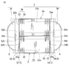
- FIG. 1 It is a schematic front view which shows the reactor of Embodiment 1.
- FIG. 2 It is a schematic top view which shows the reactor of Embodiment 1.
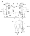
- FIG. 1 It is a schematic front view which shows the reactor of Embodiment 1.
- the temperature rise and fall are repeated as the coil is energized and de-energized.
- the winding portion and the coil-side resin member are thermally contracted as the temperature drops, the winding portion and the coil-side resin member are deformed in a direction away from each other due to the difference in thermal expansion coefficient between them and the influence of the temperature distribution. Due to this deformation, the insulating coating such as the enamel layer may be pulled and damaged.
- the self-bonding layer may repeat re-melting and re-solidification by repeating the above-described temperature rise and temperature drop.
- the self-bonding layer remelts, and the winding portion and the coil side resin member are deformed by heat and pressed against each other.
- the wound portion and the coil side resin member are reattached by the self-bonding layer.
- the winding part and the coil-side resin member are deformed by heat, and the state in which the insulating coating is pulled as described above may recur, and the insulating coating may be damaged.
- the pulling force acts on the end face plate of the coil side resin member. Therefore, as described above, the self-bonding layer repeats remelting and resolidification, and a tensile force is repeatedly applied during the deformation, so that the end face plate may be cracked.
- an object of the present disclosure is to provide a reactor in which an end surface of a winding portion is hardly damaged even if a coil including a fusion layer is provided.
- a reactor according to an aspect of the present invention is: A coil having a winding part; A magnetic core including an inner core portion disposed in the winding portion and an outer core portion disposed outside the winding portion; An outer interposed portion interposed between an end surface of the winding portion and an inner end surface of the outer core portion;
- the winding part includes a winding body, and a fusion layer provided on the outer periphery of the winding body to join adjacent turns.
- An anti-adhesion structure for preventing the end surface of the winding part and the outer interposition part from being fixed by the fusion layer is provided.
- the reactor described above includes a coil including a winding portion including a fusion layer as a constituent element, and includes an anti-adhesion structure between the end surface of the winding portion and the outer interposed portion. Therefore, the above-described reactor does not substantially generate a force for pulling the end surface of the wound portion or the outer intervening portion due to the adhesion and fixing of the fusion layer as described above. Therefore, although said reactor makes a coil provided with a melt
- Examples of the anti-adhesion structure include an anti-adhesion layer provided between the end face of the winding part and the outer interposition part.
- the material constituting the anti-adhesion layer is, for example, a material that does not substantially adhere to the fusion layer (may be adhered to the outer interposition part), or a material that does not substantially adhere to the outer interposition part (adherence to the fusion layer) Or a material that does not substantially adhere to both the fusion layer and the outer intervening portion.
- the fusion layer provided on the end surface of the winding portion does not directly contact the outer interposition portion and is substantially fixed.
- the said form uses a coil provided with a melt
- Examples of the anti-adhesion layer include a form including a sheet material made of a material that does not substantially adhere to the fusion layer.
- the fusion layer provided on the end face of the winding portion is substantially not fixed to this sheet material or the outer intervening portion.
- the said form can manufacture easily a reactor provided with the adhering prevention structure by arrange
- Examples of the sheet material include a form made of polytetrafluoroethylene (PTFE).
- the PTFE forming the sheet material is excellent in heat resistance, slipperiness, non-adhesiveness, low friction, insulation, and the like, and substantially does not melt or adhere to the fusion layer when the reactor is used. Therefore, in the above-described embodiment, the end surface of the winding portion and the outer interposed portion can be maintained in a non-adhered state by interposing the PTFE sheet material, and it is easier to prevent damage to the end surface of the winding portion and cracking of the outer interposed portion. .
- the anti-adhesion layer is made of a material that does not substantially adhere to the fusion layer, and includes a form including a coating layer applied to the outer intervening portion.
- a reactor having an anti-adhesion structure can be manufactured without increasing the number of assembly parts by forming a coating layer on the outer intervening portion in the manufacturing process. Moreover, compared with the case where an application layer is formed on the end surface of the winding part, it is easier to form the application layer. Therefore, although the above-mentioned form includes a coil having a fusion layer as a constituent element, it is possible to prevent damage to the end face of the winding part and cracking of the outer intervening part and not to increase the number of assembly steps, and to form a coating layer It is excellent in manufacturability in that it is easy to do.
- the anti-adhesion structure includes an exposed end surface in which an end surface of the winding portion does not have the fusion layer and the winding body is exposed, The form which the said exposed end surface and the said outside interposition part contact directly is mentioned.
- the fusion layer is not interposed between the end face of the winding part and the outer interposition part, the end face of the winding part and the outer interposition part are substantially not bonded and fixed by the fusion layer.
- the said form manufactures the reactor provided with the anti-adhesion structure without increasing the number of assembly parts, for example, by removing the fusion layer provided on the end face of the winding part in the manufacturing process and forming the exposed end face. it can. Therefore, although the above-mentioned form includes a coil having a fusion layer as a constituent element, it is possible to prevent damage to the end face of the winding part and cracking of the outer intervening part, and to improve productivity in that the number of assembly steps is not increased. Excellent.
- FIG. 1 is a front view of the reactor 1A as viewed from a direction (here, a direction orthogonal to the plane of FIG. 1) perpendicular to the axial direction of the coil 2 (left-right direction in FIG. 1).
- FIG. 3 to be described later is also a front view of the reactor 1B of the second embodiment as seen in FIG.
- FIG. 2 shows a direction in which the reactor 1A is orthogonal to both the axial direction of the coil 2 (left-right direction in FIG. 2) and the arrangement direction of the two winding portions 2a, 2b (up-down direction in FIG. 2) (here, FIG. 2).
- FIG. 1 and FIG. 3 It is the top view seen from the direction orthogonal to the paper surface.
- the end of the winding 2w forming the coil 2 is omitted, and the overall configuration of the reactors 1A and 1B is schematically shown. Further, the winding main body 20 and the fusion layer 22 are highlighted for easy understanding, and the thickness and the like are different from the actual dimensions.
- the lower side in FIG. 1 and FIG. 3 will be described as the installation side of the reactors 1A and 1B. This installation direction is an example, and can be changed as appropriate.
- FIG. 2 A of reactors of 1st Embodiment are provided with the coil 2 which has a winding part, the magnetic core 3 arrange
- FIG. 2 the coil 2 includes a pair of winding portions 2a and 2b. Each winding part 2a, 2b is arranged side by side so that each axis may be parallel.
- the magnetic core 3 includes inner core portions 31a and 31b disposed in the winding portions 2a and 2b, respectively, and two outer core portions 32 and 34 disposed outside the winding portions 2a and 2b.
- two outer core portions 32 and 34 are arranged so as to sandwich the inner core portions 31a and 31b arranged side by side, thereby forming an annular closed magnetic circuit.
- the interposition member 5 is formed between the one end surface 22e of the winding portions 2a and 2b and the inner end surface 32e of the one outer core portion 32, and between the other end surface 24e of the winding portions 2a and 2b and the other outer core portion 34.
- Outer interposed portions 52 and 54 interposed between the inner end surface 34e are provided.
- Reactor 1A is typically used by being attached to an installation target (not shown) such as a converter case.
- the winding portions 2a and 2b include a winding body 20 and a fusion layer 22 that is provided on the outer periphery of the winding body 20 and joins adjacent turns.
- the end surface 22e of the winding portions 2a and 2b and the outer interposition portion 52, and the end surface 24e of the winding portions 2a and 2b and the outer interposition portion 54 are fixed by the fusion layer 22, respectively.
- An anti-adhesion structure 7 is provided.
- the reactor 1A includes, as the anti-adhesion structure 7, between the end surfaces 22e of the winding portions 2a and 2b and the outer interposition portion 52, and between the end surfaces 24e of the winding portions 2a and 2b and the outer interposition portion 54.
- Each is provided with anti-adhesion layers 72 and 74.
- each component will be described in detail.
- the coil 2 provided in the reactor 1A of the first embodiment is a so-called self-bonding type coil.
- the coil 2 is typically formed in a cylindrical shape by winding a winding 2w including a winding main body 20 and a fusion layer 22 covering the outer periphery of the winding main body 20 in a spiral shape at a predetermined temperature. It is formed by solidifying after fusing layer 22 by heating. By performing the melting and solidification, adjacent turns among the plurality of turns forming the winding portions 2a and 2b are joined by the fusion layer 22.
- the fusion layer 22 is also present on the end faces 22e and 24e (see the broken line in FIGS. 1 and 2 and the broken line in the enlarged view in the one-dot chain line circle in FIG. 3 described later). That is, the winding body 20 is not substantially exposed at the winding portions 2a and 2b, and the fusion layer 22 is present on the entire surface of the winding portions 2a and 2b.
- the winding body 20 is an insulation-coated wire including a conductor wire made of copper or the like and an insulation coating that covers the outer periphery of the conductor wire.
- Examples of the constituent material of the insulating coating include resins such as polyamideimide, and typically enamel.
- the winding body 20 in this example is a covered rectangular wire.
- the fusion layer 22 may be a resin that can be thermally fused, for example, a thermosetting resin such as an epoxy resin, a silicone resin, or an unsaturated polyester.
- a thermosetting resin such as an epoxy resin, a silicone resin, or an unsaturated polyester.
- the thickness of the fusion layer 22 can be selected as appropriate as long as adjacent turns can be joined to each other, and may be thin.
- Examples of the coil 2 including the winding portions 2a and 2b arranged side by side as described above include the following modes.
- the other end of each winding part 2a, 2b is used as a connection location to which an external device such as a power source is connected.
- the winding parts 2a and 2b in this example are all cylindrical edgewise coils and have the same shape, winding direction, and number of turns.
- size, the number of turns, etc. can be selected suitably.
- the edgewise coil is easy to increase the space factor and can be a small coil 2.
- the edgewise coil has a size corresponding to the width of the winding 2 w in the face to be disposed opposite to each turn. Therefore, it is easy to ensure a large bonding area between adjacent turns, and adjacent turns can be firmly bonded by the fusion layer 22.
- the melting and solidification described above can be performed at an appropriate time after the formation of the winding portions 2a and 2b.
- the heat treatment conditions such as the heating temperature may be appropriately adjusted according to the constituent material of the fusion layer 22.
- the magnetic core 3 in this example includes the two columnar inner core portions 31a and 31b and the two columnar outer core portions 32 and 34 as described above.
- Each of the inner core portions 31a and 31b in this example is a rectangular parallelepiped assembly in which a plurality of rectangular parallelepiped core pieces (not shown) and at least one gap material (not shown) are alternately combined. Yes, same shape and same size.
- This assembly can be integrated with an adhesive or can be integrated with a resin mold portion 6 described later. Further, the gap material can be omitted or an air gap can be formed.
- the end surfaces of the inner core portions 31a and 31b are connected to the inner end surfaces 32e and 34e of the outer core portions 32 and 34, respectively.
- the outer core portions 32 and 34 in this example are both made of one columnar core piece, and have the same shape and the same size.
- the planar shape (dome shape) of the outer core portions 32 and 34 shown in FIG. 2 is an example, and can be changed as appropriate.
- the installation side surface (lower surface in FIG. 1) protrudes from the installation side surfaces (the same) of the inner core parts 31a and 31b. . Therefore, the magnetic path of the outer core parts 32 and 34 can be increased, and the length along the axial direction of the winding parts 2a and 2b (the axial direction of the inner core parts 31a and 31b) in the reactor 1A can be easily shortened.
- the reactor 1A has outer interposed portions 52 and 54 made of an insulating material between the inner end surfaces 32e and 34e of the outer core portions 32 and 34 and the end surfaces 22e and 24e of the winding portions 2a and 2b.
- the above-mentioned core piece includes a molded body mainly composed of a soft magnetic material.
- the soft magnetic material include metals such as iron and iron alloys (Fe—Si alloy, Fe—Ni alloy, etc.), and nonmetals such as ferrite.
- the molded body is a powder molded body formed by compression molding of a powder made of a soft magnetic material or a coating powder further provided with an insulation coating, a molded body of a composite material containing soft magnetic powder and a resin, or a soft steel such as an electromagnetic steel sheet. Examples include a laminate formed by laminating magnetic metal plates, and a sintered body such as a ferrite core.
- Typical examples of the gap material include a nonmagnetic material such as alumina, and a plate material made of a material having a relative permeability lower than that of the core piece.
- the interposition member 5 is typically made of an insulating material such as a resin, and functions as an insulating member between the coil 2 and the magnetic core 3. In addition, the interposition member 5 functions as a positioning member for the inner core portions 31a and 31b and the outer core portions 32 and 34 with respect to the winding portions 2a and 2b.
- the interposed member 5 includes outer interposed portions 52 and 54 interposed between the end faces 22e and 24e of the winding portions 2a and 2b and the outer core portions 32 and 34.
- the interposed member 5 of this example further includes an inner interposed portion (not shown) interposed between the winding portions 2a and 2b and the inner core portions 31a and 31b.
- the outer interposition part 52 of this example is a frame-like plate material, and two through holes 52h and 52h through which the inner core parts 31a and 31b are inserted are provided in parallel at the center (FIG. 2).
- the outer interposition part 54 is a frame-like plate material having substantially the same shape and size as the outer interposition part 52, and two through holes 54 h and 54 h through which the inner core parts 31 a and 31 b are inserted are arranged in parallel at the center. (Provided).
- One surface of the plate material forming each of the outer interposed portions 52 and 54 is a surface (hereinafter sometimes referred to as coil side surfaces 520 and 540) that is disposed to face the end surfaces 22e and 24e of the winding portions 2a and 2b.
- the other surface of the plate material is a surface (hereinafter sometimes referred to as a core side surface) that is disposed to face the inner end surfaces 32e, 34e of the outer core portions 32, 34.
- the coil side surfaces 520 and 540 of the outer interposition portions 52 and 54 can be provided with spiral grooves or protrusions (not shown) along the shapes of the end surfaces 22e and 24e of the winding portions 2a and 2b. In this case, the coil side surfaces 520 and 540 can be in close contact with the end surfaces 22e and 24e of the winding portions 2a and 2b. Therefore, it is easy to shorten the length along the axial direction of the winding portions 2a and 2b in the reactor 1A, and from this point, it is easy to reduce the size.
- the reactor 1A of the first embodiment includes the anti-adhesion layers 72 and 74, the end surfaces 22e and 24e of the winding portions 2a and 2b and the coil side surfaces 520 of the outer interposed portions 52 and 54, even when closely contacting as described above. Adhesion with 540 can be prevented. 1 to 3, the end faces 22e and 24e of the winding portions 2a and 2b are schematically shown as planes orthogonal to the axial direction of the winding portions 2a and 2b.
- the inner intervening portion is formed integrally with the outer intervening portions 52 and 54 and includes a cylindrical portion that houses at least a part of the inner core portions 31a and 31b.
- the inner interposition portion protrudes from the inner peripheral edge forming the through holes 52h and 54h toward the winding portions 2a and 2b on the coil side surfaces 520 and 540 of the outer interposition portions 52 and 54, and the inner interposition portions 31a and 31b.
- a relatively short cylindrical portion such as half or less of the length may be used.
- the inner intervening portion is a member independent of the outer intervening portions 52 and 54, or a pair of bowl-shaped members instead of the cylindrical portion, or a plurality of rod-shaped members are arranged apart from each other. And so on.
- the covering area of the inner core parts 31a, 31b in the inner interposition part can be made smaller.
- the inner intervening portion can be omitted. Even in this case, the insulation between the winding parts 2a, 2b and the inner core parts 31a, 31b can be enhanced by the intervention of the resin mold part 6.
- Examples of the constituent material of the interposition member 5 include an insulating material such as a resin.
- Specific resins include polyphenylene sulfide (PPS) resin, PTFE resin, liquid crystal polymer (LCP), polyamide (PA) resin such as nylon 6 and nylon 66, polybutylene terephthalate (PBT) resin, acrylonitrile butadiene styrene (ABS)
- thermoplastic resins such as resins.
- thermosetting resins such as unsaturated polyester resin, an epoxy resin, a urethane resin, and a silicone resin, are mentioned.
- the interposition member 5 can be manufactured by a known molding method such as injection molding.
- the end surfaces 22e and 24e of the winding portions 2a and 2b and the coil side surfaces 520 and 540 of the outer interposed portions 52 and 54, which are opposed to each other as described above, are the fusion layer 22 of the coil 2.
- the anti-adhesion structure 7 is provided so as not to adhere.
- anti-adhesion layers 72, 74 are provided between the end faces 22e, 24e of the winding portions 2a, 2b and the coil side surfaces 520, 540 of the outer interposed portions 52, 54 as in this example.
- the end surfaces of the winding portions 2a and 2b do not have the fusion layer 22, and the exposed end surface 20e is provided (FIG. 3).
- the anti-adhesion layers 72 and 74 will be described in detail.
- Examples of the anti-adhesion layers 72 and 74 include a form containing a sheet material.
- the reactor 1A including the anti-adhesion structure 7 is easily manufactured by disposing the sheet material between the end surfaces 22e, 24e of the winding portions 2a, 2b and the outer interposed portions 52, 54 in the manufacturing process. it can.
- constituent material of the sheet material examples include the following.
- a material that does not substantially adhere to the outer interposition portions 52 and 54 may be adhered to the fusion layer 22).
- the fusion layer 22 provided on the end faces 22e and 24e of the winding portions 2a and 2b is the sheet material. Due to the interposition, the outer intervening portions 52 and 54 are not directly in contact with each other, and the outer intervening portions 52 and 54 are substantially not fixed, and the sheet material itself is not substantially fixed. Examples of such a sheet material include those made of PTFE. PTFE is excellent in heat resistance, slipperiness, non-adhesiveness, low friction, insulation, etc., and is practically melted when the reactor 1A is used or melted and adhered to the fusion layer 22. Not. Also from this, it is expected that a form including a sheet material made of PTFE can be suitably used as the anti-adhesion layers 72 and 74.
- the sheet material made of the material (ii) is fixed to the outer interposition portions 52 and 54 by the fixing force of the sheet material itself, or separately adhered with an adhesive, etc.
- the outer interposed parts 52 and 54 provided can be prepared.
- the thickness of the sheet material can be appropriately selected as long as it can prevent the end faces 22e and 24e of the winding portions 2a and 2b and the outer interposition portions 52 and 54 from being stuck by the fusion layer 22.
- the sheet material may be thin.
- the thickness is about 10 ⁇ m or more and 300 ⁇ m or less.
- a form having a partially different thickness can be employed.
- the surfaces of the sheet material facing the end surfaces 22e and 24e of the winding portions 2a and 2b are spiral inclined surfaces along the end surfaces 22e and 24e.
- the surface which opposes the outer interposition parts 52 and 54 in is a plane which is orthogonal to the axial direction of the winding parts 2a and 2b. If the outer dimension of the sheet material is larger than the size of the end faces 22e and 24e of the winding portions 2a and 2b or the size of the coil side surfaces 520 and 540 of the outer interposition portions 52 and 54, the sticking can be prevented more reliably. it can.
- the shape of the sheet material can be appropriately selected as long as it can prevent the end faces 22e and 24e of the winding portions 2a and 2b and the outer interposition portions 52 and 54 from being stuck by the fusion layer 22.
- the shape is made to correspond to the end faces 22e, 24e of the winding parts 2a, 2b or the coil side faces 520, 540 of the outer interposition parts 52, 54, the sticking can be prevented more reliably.
- the anti-adhesion layers 72 and 74 may include, for example, a coating layer that is applied to at least one of the end surfaces 22e and 24e of the winding portions 2a and 2b and the coil side surfaces 520 and 540 of the outer interposed portions 52 and 54. It is done.
- the coating layer is formed on the end surfaces 22e and 24e of the winding portions 2a and 2b and the coil side surfaces 520 and 540 of the outer interposition portions 52 and 54 in the manufacturing process without increasing the number of assembly parts.
- the reactor 1A including the sticking prevention structure 7 can be manufactured.
- the positions of the anti-adhesion layers 72 and 74 are not substantially shifted, and the anti-adhesion structure 7 can be maintained for a long time.
- Examples of the constituent material of the coating layer include the following.
- the coating layer is made of a material ( ⁇ ) that does not substantially adhere to the fusion layer 22 and is applied to the coil side surfaces 520 and 540 of the outer interposed portions 52 and 54, the end surfaces 22e of the winding portions 2a and 2b are included. , 24e is not in direct contact with the outer interposition portions 52, 54 due to the interposition of the coating layer. Further, the fusion layer 22 is not substantially fixed to the outer interposition portions 52 and 54 and is not substantially fixed to the coating layer itself. Furthermore, compared with the case where the coating layer is formed on the end faces 22e and 24e of the winding portions 2a and 2b in the manufacturing process, the coating layer is more formed on the coil side surfaces 520 and 540 of the outer interposed portions 52 and 54. In this respect, it is excellent in manufacturability. Examples of the constituent material for such a coating layer include fluorine compounds and silicone compounds.
- the thickness of the coating layer can be appropriately selected as long as it is possible to prevent the fusion layer 22 from sticking to the end faces 22e, 24e of the winding portions 2a, 2b and the outer interposition portions 52, 54.
- the coating layer may be thin as long as the above sticking can be prevented.
- the thickness is about 0.1 ⁇ m or more and 20 ⁇ m or less.
- the coating layer is formed corresponding to the end surfaces 22e and 24e of the winding portions 2a and 2b to be coated and the coil side surfaces 520 and 540 of the outer interposition portions 52 and 54, so that the above-described fixing can be more reliably performed. Can be prevented.
- the anti-adhesion layers 72 and 74 may include, for example, a form including both the above-described sheet material and the above-described coating layer.
- the above-described sheet material is provided between one end surface 22e of the winding portions 2a and 2b and the outer interposed portion 52, and the above-described portion is provided between the other end surface 24e of the winding portions 2a and 2b and the outer interposed portion 54.
- the form provided with the coating layer of this is mentioned.
- the sheet material described above is provided between a part of one end face 22e of the winding parts 2a and 2b and a part of the outer interposition part 52, and the other end face 22e of the winding parts 2a and 2b.
- a configuration in which the above-described coating layer is provided between the portion and the other portion of the outer interposed portion 52 is exemplified.
- the reactor 1 ⁇ / b> A can include a resin mold portion 6 that covers at least a part of the outer periphery of the combined body including the coil 2, the magnetic core 3, and the interposition member 5.
- the resin mold portion 6 includes an outer resin portion that covers at least a part of the outer periphery of the outer core portions 32 and 34, and an inner resin portion that is interposed between the winding portions 2a and 2b and the inner core portions 31a and 31b. And providing.
- the outer resin portion is virtually shown by a two-dot chain line, and the inner resin portion is not shown.
- the outer resin portion and the inner resin portion can be formed as a continuous integral molded product or an independent molded product. In the case of the integrally molded product, the shape and size of the through holes 52h and 54h of the outer interposed portions 52 and 54 may be adjusted so that the inner resin portion can be formed.
- the reactor 1 ⁇ / b> A can easily reduce noise and vibration. If the anti-adhesion layers 72 and 74 are not provided, and the outer intervening portions 52 and 54 and the magnetic core 3 are integrated by the resin mold portion 6, as described above, due to the cooling / heating cycle when the reactor 1 ⁇ / b> A is used.
- the force which pulls the end surfaces 22e and 24e of the winding parts 2a and 2b is easily generated.
- the reactor 1A of the first embodiment includes the anti-adhesion layers 72 and 74, even if the outer interposition parts 52 and 54 and the magnetic core 3 are integrated by the resin mold part 6, the winding parts 2a and 2b.
- the pulling force of the end faces 22e and 24e is not substantially generated, and the insulating coating is easily damaged.
- the outer resin part can include an attachment part (not shown) for fixing the reactor 1A to the installation target.
- Examples of the constituent resin of the resin mold portion 6 include PPS resin, PTFE resin, LCP, nylon 6, nylon 66, nylon 10T, nylon 9T, nylon 6T, and other PA resins, and PBT resin. When these resins contain a filler having excellent thermal conductivity, the resin mold portion 6 having excellent heat dissipation can be obtained. Injection molding or the like can be used for molding the resin mold portion 6.
- the reactor 1 ⁇ / b> A of the first embodiment can be basically manufactured by assembling the coil 2, the magnetic core 3, and the interposition member 5.
- the anti-adhesion layers 72 and 74 include a sheet material
- the sheet in the assembly process described above, the sheet is interposed between the end surfaces 22e and 24e of the winding portions 2a and 2b and the coil side surfaces 520 and 540 of the outer interposition portions 52 and 54.
- the material is also assembled.
- the fusion layer 22 is melted and solidified in advance.
- the coating layer is formed on the end surfaces 22e and 24e of the winding portions 2a and 2b and the coil side surfaces 520 and 540 of the outer interposition portions 52 and 54. Are prepared, and the coil 2, the magnetic core 3, and the interposition member 5 are assembled.
- the coating layer is formed on the end faces 22e and 24e of the winding portions 2a and 2b, typically, the fusion layer 22 is melted and solidified before the coating layer is formed.
- the fusion layer 22 may be melted and solidified at an appropriate time.
- the assembly assembled as described above may be stored in a resin mold and the resin mold portion 6 may be molded so as to cover a predetermined portion of the combination.
- the reactor 1A of the first embodiment can be used for circuit components that perform voltage step-up and step-down operations, such as various converters and components of power conversion devices.
- the converter include an in-vehicle converter (typically a DC-DC converter) mounted on a vehicle such as a hybrid vehicle, a plug-in hybrid vehicle, an electric vehicle, and a fuel cell vehicle, an air conditioner converter, and the like.
- the reactor 1A according to the first embodiment includes the coil 2 including the fusion layer 22 as a constituent element, and the anti-adhesion structure 7 between the end surfaces 22e and 24e of the winding portions 2a and 2b and the outer interposed portions 52 and 54. Prepare. Therefore, when the reactor 1A is used, the end surfaces 22e and 24e of the winding portions 2a and 2b and the outer interposition portions 52 and 54 are bonded and fixed by the fusion layer 22 of the end surfaces 22e and 24e of the winding portions 2a and 2b. There is virtually nothing.
- the reactor 1A includes the coil 2 including the fusion layer 22 as a constituent element, the insulation coating of the winding body 20 that forms the end faces 22e and 24e of the winding portions 2a and 2b, particularly the end faces 22e and 24e, is described above. There is virtually no breakage due to adhesive fixation. Further, in the reactor 1A, the outer intervening portions 52 and 54 are not substantially cracked due to the above-described adhesive fixing.
- Reactor 1A of this example has anti-adhesion layers 72 and 74 interposed between end surfaces 22e and 24e of winding portions 2a and 2b and coil side surfaces 520 and 540 of outer interposition portions 52 and 54 as anti-adhesion structure 7.
- the following effects can be obtained. (1) Since the fusion layer 22 provided on the end surfaces 22e and 24e of the winding portions 2a and 2b does not substantially adhere to the outer interposition portions 52 and 54, the end surfaces 22e and 24e of the winding portions 2a and 2b described above. It is easier to prevent damage, particularly damage to the insulation coating.
- the anti-adhesion layers 72 and 74 include the above-described sheet material
- the end surfaces 22e and 24e of the winding portions 2a and 2b and the coil side surfaces 520 and 540 of the outer interposition portions 52 and 54 What is necessary is just to arrange
- the productivity is excellent in that the reactor 1A including the anti-adhesion structure 7 can be manufactured without increasing the number of assembly parts.
- the reactor 1A of Embodiment 1 can include at least one of the following. The same applies to Embodiment 2, which will be described later, and a modified example.
- a Sensor (not shown) for measuring the physical quantity of reactor 1A such as a temperature sensor, a current sensor, a voltage sensor, and a magnetic flux sensor
- B A heat radiating plate (for example, a metal plate) attached to at least a part of the outer peripheral surface of the coil 2
- C A bonding layer interposed between the installation surface of the reactor 1A and the installation target or the heat sink of (b) (for example, an adhesive layer, preferably having excellent insulating properties).
- the reactor 1B of Embodiment 2 has the same basic configuration as the reactor 1A according to the first embodiment.
- the coil 2 includes the fusion layer 22, the magnetic core 3, and the interposition member 5 including the outer interposition portions 52 and 54.
- a resin mold portion 6 is provided as appropriate.
- the reactor 1B includes an anti-adhesion structure 7 that prevents the end surfaces of the winding portions 2a and 2b and the outer interposed portions 52 and 54 from adhering to each other by the fusion layer 22. .
- the reactor 1B is different from the first embodiment in that the anti-adhesion structure 7 is not provided with the anti-adhesion layers 72 and 74.
- the reactor 1B has an exposed end surface 20e in which the end surfaces of the winding portions 2a and 2b do not have the fusion layer 22 and the winding body 20 is exposed as the anti-adhesion structure 7, and the exposed end surface 20e and the outer interposition are provided.
- the coil side surfaces 520 and 540 of the parts 52 and 54 are in direct contact.
- the coil 2 provided in the reactor 1B of the second embodiment is a so-called self-fused coil in which adjacent turns are joined by a fusion layer 22 as in the first embodiment.
- the coil 2 has a fusion layer 22 on the inner and outer peripheral surfaces of the winding portions 2a and 2b in addition to the turns (see the broken line in FIG. 3). However, the end face of the winding portions 2a and 2b is removed from the fusion layer 22, and the winding body 20 is exposed (see an enlarged view in a one-dot chain line circle in FIG. 3).
- the coil 2 that does not include the locally fused layer 22 as described above is formed as follows, for example. As described in the first embodiment, after winding the winding 2w whose outer periphery of the winding body 20 is covered with the fusion layer 22 in a spiral shape, the winding 2w is melted and solidified to form the winding portions 2a and 2b. A coil having the fusion layer 22 on the entire surface is produced. The winding main body 20 is exposed by removing the fusion layer 22 on the end faces of the winding portions 2a and 2b. By doing so, the coil 2 having the exposed end face 20e is obtained.
- the fusion layer 22 For removal of the fusion layer 22, it is possible to use an appropriate solvent that can remove the fusion layer 22 and that does not substantially dissolve the insulating coating, or to polish it. In the case of using the above-mentioned solvent, if the masking is performed on the portion where the fusion layer 22 is not removed and the portion where the fusion layer 22 is not removed, the fusion layer 22 can be reliably removed only at a desired portion. Furthermore, with respect to the winding 2w that makes a turn in the vicinity of the exposed end face 20e, the fusion layer 22 provided on the inner and outer peripheral surfaces of the winding portions 2a and 2b can be removed or locally thinned. In the enlarged view in the one-dot chain line circle of FIG.
- the thickness of the fusion layer 22 in the vicinity of the exposed end surface 20e is increased toward the exposed end surface 20e.
- the continuously thinned form is illustrated.
- the inclined surface it is possible to adopt a form having a step surface in which the thickness is gradually reduced.
- the fusion layer 22 on the inner and outer circumferential surfaces of the winding portions 2a and 2b is melted when the reactor 1B is used, It is easy to prevent leakage between the exposed end surface 20e and the outer interposed portions 52 and 54. Note that the coating layer that becomes the fusion layer 22 may be partially removed before melting and solidification.
- the reactor 1B of Embodiment 2 can be manufactured by preparing and assembling the coil 2, the magnetic core 3, and the interposition member 5 having the exposed end surface 20e as described above, for example.
- the resin mold portion 6 may be molded so as to cover a predetermined portion of the assembled assembly.
- the reactor 1B according to the second embodiment includes the coil 2 including the fusion layer 22 as a constituent element, but is fixed between the end surfaces of the winding portions 2a and 2b and the outer interposed portions 52 and 54.
- a prevention structure 7 is provided. Accordingly, the reactor 1B according to the first embodiment is similar to the first embodiment in that the end surfaces of the winding portions 2a and 2b caused by adhesion and fixing by the fusion layer 22, particularly damage to the insulation coating, Breaking can be prevented.
- the reactor 1B according to the second embodiment has a structure in which the fusion-bonding layer 22 is not interposed between the end surfaces of the winding portions 2a and 2b and the outer interposed portions 52 and 54 as the sticking prevention structure 7. Therefore, in the reactor 1 ⁇ / b> B, the end surfaces of the winding portions 2 a and 2 b and the outer interposition portions 52 and 54 are substantially not bonded and fixed by the fusion layer 22. Such a reactor 1B can maintain the end surfaces of the winding parts 2a and 2b and the outer interposition parts 52 and 54 in a healthy manner over a long period of time.
- the reactor 1B having the anti-adhesion structure 7 can be manufactured, and the reactor 1B is manufactured in that the number of parts to be assembled and the number of assembly processes are not increased. Excellent in properties.
- the anti-adhesion layers 72 and 74 are interposed. By doing so, it is possible to more reliably prevent the end surfaces 22e, 24e of the winding portions 2a, 2b and the outer interposed portions 52, 54 from sticking for a long period of time.
- winding 2w which forms the coil 2 be a covering round wire etc. provided with the conductor wire of a round wire and insulation coating.
- the coil 2 includes only one winding part, and the magnetic core 3 includes a middle magnetic leg part in which the winding part is disposed and two side magnetic leg parts arranged in parallel with the middle magnetic leg part. And a pair of plate-like connecting portions sandwiching three magnetic leg portions arranged in parallel. Examples of such a magnetic core 3 include what are called an EI type core, an EE type core, an ER type core, and the like.
Landscapes
- Engineering & Computer Science (AREA)
- Power Engineering (AREA)
- Insulating Of Coils (AREA)
Abstract
巻回部を有するコイルと、前記巻回部内に配置される内側コア部と、前記巻回部外に配置される外側コア部とを含む磁性コアと、前記巻回部の端面と、前記外側コア部の内端面との間に介在される外側介在部とを備え、前記巻回部は、巻線本体と、前記巻線本体の外周に設けられて、隣り合うターン同士を接合する融着層とを備え、前記巻回部の端面と前記外側介在部とが前記融着層によって固着することを防止する固着防止構造を備えるリアクトル。
Description
本発明は、リアクトルに関する。
本出願は、2017年05月29日付の日本国出願の特願2017-106035に基づく優先権を主張し、前記日本国出願に記載された全ての記載内容を援用するものである。
本出願は、2017年05月29日付の日本国出願の特願2017-106035に基づく優先権を主張し、前記日本国出願に記載された全ての記載内容を援用するものである。
特許文献1は、自己融着層を備える平角線からなるコイル本体を含むコイルと、環状のコアと、コイル側樹脂部材及びコア側樹脂部材とを備えるリアクトルを開示する。上記コイル側樹脂部材は、コイル本体の巻回部の端面を覆い、自己融着層によってこの端面と接着固定される端面板と、端面板から突出し、リアクトルの設置対象への固定片をなすブラケットとを備える。上記コアは、巻回部内に配置される脚部(内側コア部)と、巻回部外に配置される部分(外側コア部)を含む一対のC字状のヨーク部とからなる。上記コア側樹脂部材は、各ヨーク部を埋設する部分と、上記脚部を収納する筒状のボビンとが一体成形されてなる。上記端面板は、巻回部の端面と、ヨーク部の内端面との間に介在される。
上述の平角線は、代表的には、銅からなる導体線がエナメル層で覆われた絶縁被覆線である。自己融着層は、エナメル層といった絶縁被覆の外周に設けられる。
本開示のリアクトルは、
巻回部を有するコイルと、
前記巻回部内に配置される内側コア部と、前記巻回部外に配置される外側コア部とを含む磁性コアと、
前記巻回部の端面と、前記外側コア部の内端面との間に介在される外側介在部とを備え、
前記巻回部は、巻線本体と、前記巻線本体の外周に設けられて、隣り合うターン同士を接合する融着層とを備え、
前記巻回部の端面と前記外側介在部とが前記融着層によって固着することを防止する固着防止構造を備える。
巻回部を有するコイルと、
前記巻回部内に配置される内側コア部と、前記巻回部外に配置される外側コア部とを含む磁性コアと、
前記巻回部の端面と、前記外側コア部の内端面との間に介在される外側介在部とを備え、
前記巻回部は、巻線本体と、前記巻線本体の外周に設けられて、隣り合うターン同士を接合する融着層とを備え、
前記巻回部の端面と前記外側介在部とが前記融着層によって固着することを防止する固着防止構造を備える。
[本開示が解決しようとする課題]
上述のように自己融着層を備えるコイルを構成要素とし、コイルの巻回部の端面とコイル側樹脂部材とを自己融着層によって接着固定したリアクトルでは、その使用時に上記巻回部の端面を破損し得るという問題がある。特に、上記巻回部の端面をなす平角線のエナメル層が後述するように破損し得る。
上述のように自己融着層を備えるコイルを構成要素とし、コイルの巻回部の端面とコイル側樹脂部材とを自己融着層によって接着固定したリアクトルでは、その使用時に上記巻回部の端面を破損し得るという問題がある。特に、上記巻回部の端面をなす平角線のエナメル層が後述するように破損し得る。
上述のリアクトルの使用時、コイルへの通電、非通電に伴って、温度上昇と温度降下とが繰り返される。温度降下に伴って巻回部とコイル側樹脂部材とが熱収縮すると、両者の熱膨張係数の差と温度分布の影響とによって、巻回部とコイル側樹脂部材とが離れる方向に変形する。この変形によってエナメル層といった絶縁被覆が引っ張られて破損し得る。
また、上述の温度上昇と温度降下との繰り返しによって、自己融着層が再溶融と再固化とを繰り返すことがある。温度上昇に伴って自己融着層が再溶融すると共に、巻回部及びコイル側樹脂部材が熱によって変形して互いに押し付け合う。この状態で温度降下して自己融着層の固化温度に達し、再固化すれば、巻回部とコイル側樹脂部材とが自己融着層によって再接着される。再接着された後に熱によって巻回部とコイル側樹脂部材とが変形して、上述のように絶縁被覆が引っ張られる状態が再発し、絶縁被覆を破損し得る。
更に、上述の離反する方向の変形時、コイル側樹脂部材の端面板にも引っ張る力が作用する。そのため、上述のように自己融着層が再溶融と再固化とを繰り返すと共に上記変形時に引張力が繰り返し負荷されることで、上記端面板に割れが生じる可能性もある。
そこで、本開示は、融着層を含むコイルを備えていても、巻回部の端面を破損し難いリアクトルを提供することを目的の一つとする。
[本開示の効果]
上記の本開示のリアクトルは、融着層を含むコイルを備えていても、巻回部の端面を破損し難い。
上記の本開示のリアクトルは、融着層を含むコイルを備えていても、巻回部の端面を破損し難い。
[本願発明の実施形態の説明]
最初に、本願発明の実施態様を列記して説明する。
(1)本願発明の一態様に係るリアクトルは、
巻回部を有するコイルと、
前記巻回部内に配置される内側コア部と、前記巻回部外に配置される外側コア部とを含む磁性コアと、
前記巻回部の端面と、前記外側コア部の内端面との間に介在される外側介在部とを備え、
前記巻回部は、巻線本体と、前記巻線本体の外周に設けられて、隣り合うターン同士を接合する融着層とを備え、
前記巻回部の端面と前記外側介在部とが前記融着層によって固着することを防止する固着防止構造を備える。
最初に、本願発明の実施態様を列記して説明する。
(1)本願発明の一態様に係るリアクトルは、
巻回部を有するコイルと、
前記巻回部内に配置される内側コア部と、前記巻回部外に配置される外側コア部とを含む磁性コアと、
前記巻回部の端面と、前記外側コア部の内端面との間に介在される外側介在部とを備え、
前記巻回部は、巻線本体と、前記巻線本体の外周に設けられて、隣り合うターン同士を接合する融着層とを備え、
前記巻回部の端面と前記外側介在部とが前記融着層によって固着することを防止する固着防止構造を備える。
上記のリアクトルは、融着層を備える巻回部を含むコイルを構成要素とすると共に、巻回部の端面と外側介在部との間に固着防止構造を備える。そのため、上記のリアクトルは、使用時、上述のような融着層の接着固定に起因する巻回部の端面や外側介在部を引っ張る力が実質的に生じない。従って、上記のリアクトルは、融着層を備えるコイルを構成要素とするものの、巻回部の端面を破損し難い。特に、巻回部の端面をなす巻線本体にエナメル層といった絶縁被覆を備えていても、上述の引張力によって絶縁被覆を破損することが実質的にない。また、上記のリアクトルは、上記引張力によって外側介在部が割れることも実質的にない。
(2)上記のリアクトルの一例として、
前記固着防止構造は、前記巻回部の端面と前記外側介在部との間に固着防止層を備える形態が挙げられる。固着防止層の構成材料は、例えば、融着層と実質的に固着しない材料(外側介在部とは固着してもよい)、外側介在部と実質的に固着しない材料(融着層とは固着してもよい)、融着層及び外側介在部の双方と実質的に固着しない材料が挙げられる。
前記固着防止構造は、前記巻回部の端面と前記外側介在部との間に固着防止層を備える形態が挙げられる。固着防止層の構成材料は、例えば、融着層と実質的に固着しない材料(外側介在部とは固着してもよい)、外側介在部と実質的に固着しない材料(融着層とは固着してもよい)、融着層及び外側介在部の双方と実質的に固着しない材料が挙げられる。
上記形態は巻回部の端面と外側介在部との間に固着防止層を備えるため、巻回部の端面に備える融着層は、外側介在部に直接接触せず、固着することが実質的にない。従って、上記形態は、融着層を備えるコイルを構成要素とするものの、巻回部の端面、特に絶縁被覆の破損や外側介在部の割れを防止できる。
(3)上記(2)のリアクトルの一例として、
前記固着防止層は、前記融着層と実質的に固着しない材料からなるシート材を含む形態が挙げられる。
前記固着防止層は、前記融着層と実質的に固着しない材料からなるシート材を含む形態が挙げられる。
上記形態は、上述の特定のシート材を備えるため、巻回部の端面に備える融着層は、このシート材にも外側介在部にも固着することが実質的にない。また、上記形態は、製造過程で巻回部の端面と外側介在部との間に上述の特定のシート材を配置することで固着防止構造を備えるリアクトルを容易に製造できる。従って、上記形態は、融着層を備えるコイルを構成要素とするものの、巻回部の端面の破損や外側介在部の割れを防止できる上に、製造性にも優れる。
(4)上記(3)のリアクトルの一例として、
前記シート材は、ポリテトラフルオロエチレン(PTFE)からなる形態が挙げられる。
前記シート材は、ポリテトラフルオロエチレン(PTFE)からなる形態が挙げられる。
上記シート材をなすPTFEは、耐熱性、滑り性、非粘着性、低摩擦性、絶縁性などに優れ、リアクトルの使用時に溶融したり融着層に接着したりすることが実質的にない。従って、上記形態は、PTFE製のシート材の介在によって巻回部の端面と外側介在部とを非接着状態に維持でき、巻回部の端面の破損や外側介在部の割れをより防止し易い。
(5)上記(2)のリアクトルの一例として、
前記固着防止層は、前記融着層と実質的に固着しない材料からなり、前記外側介在部に塗布された塗布層を含む形態が挙げられる。
前記固着防止層は、前記融着層と実質的に固着しない材料からなり、前記外側介在部に塗布された塗布層を含む形態が挙げられる。
上記形態は、製造過程で外側介在部に塗布層を形成することで、組立部品点数を増加させずに、固着防止構造を備えるリアクトルを製造できる。また、巻回部の端面に塗布層を形成する場合に比較して、塗布層を形成し易い。従って、上記形態は、融着層を備えるコイルを構成要素とするものの、巻回部の端面の破損や外側介在部の割れを防止できる上に、組立工程数を増加しない点、塗布層を形成し易い点で製造性にも優れる。
(6)上記のリアクトルの一例として、
前記固着防止構造は、前記巻回部の端面が前記融着層を有しておらず、前記巻線本体が露出されてなる露出端面を備え、
前記露出端面と前記外側介在部とが直接接触する形態が挙げられる。
前記固着防止構造は、前記巻回部の端面が前記融着層を有しておらず、前記巻線本体が露出されてなる露出端面を備え、
前記露出端面と前記外側介在部とが直接接触する形態が挙げられる。
上記形態は巻回部の端面と外側介在部との間に融着層が介在しないため、巻回部の端面と外側介在部とが融着層によって接着固定されることが実質的にない。また、上記形態は、例えば、製造過程で巻回部の端面に備える融着層を除去して露出端面を形成することで、組立部品点数を増加させずに、固着防止構造を備えるリアクトルを製造できる。従って、上記形態は、融着層を備えるコイルを構成要素とするものの、巻回部の端面の破損や外側介在部の割れを防止できる上に、組立工程数を増加しない点で製造性にも優れる。
[本願発明の実施形態の詳細]
以下、図面を参照して、本願発明の実施形態を具体的に説明する。図中の同一符号は同一名称物を示す。
以下、図面を参照して、本願発明の実施形態を具体的に説明する。図中の同一符号は同一名称物を示す。
[実施形態1]
主に図1,図2を参照して、実施形態1のリアクトル1Aを説明する。
図1は、リアクトル1Aをコイル2の軸方向(図1では左右方向)に直交する方向(ここでは図1の紙面に直交する方向)から見た正面図である。後述する図3も実施形態2のリアクトル1Bを図1と同様にみた正面図である。
図2は、リアクトル1Aをコイル2の軸方向(図2では左右方向)及び二つの巻回部2a,2bの並び方向(図2では上下方向)の双方に直交する方向(ここでは図2の紙面に直交する方向)から見た上面図である。
図1,図2、及び後述する図3では分かり易いように、コイル2を形成する巻線2wの端部を省略し、リアクトル1A,1Bの全体構成を模式的に示す。また、巻線本体20や融着層22が分かり易いように強調して示し、厚さなどは実際の寸法と異なる。
以下の説明では、図1,図3の紙面下側をリアクトル1A,1Bの設置側として説明する。この設置方向は例示であり、適宜変更できる。
主に図1,図2を参照して、実施形態1のリアクトル1Aを説明する。
図1は、リアクトル1Aをコイル2の軸方向(図1では左右方向)に直交する方向(ここでは図1の紙面に直交する方向)から見た正面図である。後述する図3も実施形態2のリアクトル1Bを図1と同様にみた正面図である。
図2は、リアクトル1Aをコイル2の軸方向(図2では左右方向)及び二つの巻回部2a,2bの並び方向(図2では上下方向)の双方に直交する方向(ここでは図2の紙面に直交する方向)から見た上面図である。
図1,図2、及び後述する図3では分かり易いように、コイル2を形成する巻線2wの端部を省略し、リアクトル1A,1Bの全体構成を模式的に示す。また、巻線本体20や融着層22が分かり易いように強調して示し、厚さなどは実際の寸法と異なる。
以下の説明では、図1,図3の紙面下側をリアクトル1A,1Bの設置側として説明する。この設置方向は例示であり、適宜変更できる。
(リアクトル)
〈概要〉
実施形態1のリアクトル1Aは、巻回部を有するコイル2と、巻回部内外に配置される磁性コア3と、コイル2と磁性コア3との間に介在される介在部材5とを備える。この例では、図2に示すように、コイル2は、一対の巻回部2a,2bを備える。各巻回部2a,2bは、各軸が平行するように横並びに配置される。磁性コア3は、巻回部2a,2b内にそれぞれ配置される内側コア部31a,31bと、巻回部2a,2b外に配置される二つの外側コア部32,34とを含む。この磁性コア3は、横並びされる内側コア部31a,31bを挟むように二つの外側コア部32,34が配置されて、環状の閉磁路を形成する。介在部材5は、巻回部2a,2bの一方の端面22eと一方の外側コア部32の内端面32eとの間、巻回部2a,2bの他方の端面24eと他方の外側コア部34の内端面34eとの間に介在される外側介在部52,54を備える。リアクトル1Aは、代表的には、コンバータケースなどの設置対象(図示せず)に取り付けられて使用される。
〈概要〉
実施形態1のリアクトル1Aは、巻回部を有するコイル2と、巻回部内外に配置される磁性コア3と、コイル2と磁性コア3との間に介在される介在部材5とを備える。この例では、図2に示すように、コイル2は、一対の巻回部2a,2bを備える。各巻回部2a,2bは、各軸が平行するように横並びに配置される。磁性コア3は、巻回部2a,2b内にそれぞれ配置される内側コア部31a,31bと、巻回部2a,2b外に配置される二つの外側コア部32,34とを含む。この磁性コア3は、横並びされる内側コア部31a,31bを挟むように二つの外側コア部32,34が配置されて、環状の閉磁路を形成する。介在部材5は、巻回部2a,2bの一方の端面22eと一方の外側コア部32の内端面32eとの間、巻回部2a,2bの他方の端面24eと他方の外側コア部34の内端面34eとの間に介在される外側介在部52,54を備える。リアクトル1Aは、代表的には、コンバータケースなどの設置対象(図示せず)に取り付けられて使用される。
実施形態1のリアクトル1Aでは、巻回部2a,2bは、巻線本体20と、巻線本体20の外周に設けられて、隣り合うターン同士を接合する融着層22とを備える。かつ、実施形態1のリアクトル1Aは、巻回部2a,2bの端面22eと外側介在部52、巻回部2a,2bの端面24eと外側介在部54がそれぞれ融着層22によって固着することを防止する固着防止構造7を備える。この例のリアクトル1Aは、固着防止構造7として、巻回部2a,2bの端面22eと外側介在部52との間、及び巻回部2a,2bの端面24eと外側介在部54との間のそれぞれに固着防止層72,74を備える。
以下、構成要素ごとに詳細に説明する。
以下、構成要素ごとに詳細に説明する。
〈コイル〉
実施形態1のリアクトル1Aに備えるコイル2は、いわゆる自己融着型のコイルである。このコイル2は、代表的には、巻線本体20と巻線本体20の外周を覆う融着層22とを備える巻線2wを螺旋状に巻回して筒状に形成し、所定の温度に加熱して融着層22を溶融した後、固化することで形成される。上記溶融及び固化を行うことで、各巻回部2a,2bをなす複数のターンのうち、隣り合うターン同士を融着層22によって接合する。上記巻線2wで形成されることで、後述の実施形態2のように融着層22を除去する場合を除いて、ターン間に加えて、各巻回部2a,2bの内周面、外周面、及び端面22e,24eにも融着層22が存在する(図1,図2の破線、後述する図3の一点鎖線円内の拡大図の破線参照)。即ち、巻回部2a,2bにおいて巻線本体20が露出された箇所は実質的になく、巻回部2a,2bの全面に融着層22が存在する。
実施形態1のリアクトル1Aに備えるコイル2は、いわゆる自己融着型のコイルである。このコイル2は、代表的には、巻線本体20と巻線本体20の外周を覆う融着層22とを備える巻線2wを螺旋状に巻回して筒状に形成し、所定の温度に加熱して融着層22を溶融した後、固化することで形成される。上記溶融及び固化を行うことで、各巻回部2a,2bをなす複数のターンのうち、隣り合うターン同士を融着層22によって接合する。上記巻線2wで形成されることで、後述の実施形態2のように融着層22を除去する場合を除いて、ターン間に加えて、各巻回部2a,2bの内周面、外周面、及び端面22e,24eにも融着層22が存在する(図1,図2の破線、後述する図3の一点鎖線円内の拡大図の破線参照)。即ち、巻回部2a,2bにおいて巻線本体20が露出された箇所は実質的になく、巻回部2a,2bの全面に融着層22が存在する。
巻線本体20は、銅などからなる導体線と、導体線の外周を覆う絶縁被覆とを備える絶縁被覆線である。絶縁被覆の構成材料は、ポリアミドイミドなどの樹脂、代表的にはエナメルなどが挙げられる。この例の巻線本体20は、被覆平角線である。
融着層22は、熱融着が可能な樹脂、例えば、エポキシ樹脂、シリコーン樹脂、不飽和ポリエステルといった熱硬化性樹脂などが挙げられる。融着層22の厚さは、隣り合うターン同士を接合できる範囲で適宜選択でき、薄くてもよい。
上述のように横並びされる巻回部2a,2bを備えるコイル2として、例えば、以下の形態が挙げられる。
(α)1本の連続する巻線2wが螺旋状に巻回されてなる筒状の巻回部2a,2bと、この巻線2wの一部からなり、巻回部2a,2bの一端部同士を連結する連結部(図示せず)とを備える形態。
(β)独立した2本の巻線2w,2wによってそれぞれ形成された巻回部2a,2bと、両巻線2w,2wの一端部同士を溶接や圧着などによって接合する接合部とを備える形態。
各巻回部2a,2bの他端部は、電源などの外部装置が接続される接続箇所として利用される。
(α)1本の連続する巻線2wが螺旋状に巻回されてなる筒状の巻回部2a,2bと、この巻線2wの一部からなり、巻回部2a,2bの一端部同士を連結する連結部(図示せず)とを備える形態。
(β)独立した2本の巻線2w,2wによってそれぞれ形成された巻回部2a,2bと、両巻線2w,2wの一端部同士を溶接や圧着などによって接合する接合部とを備える形態。
各巻回部2a,2bの他端部は、電源などの外部装置が接続される接続箇所として利用される。
その他、この例の巻回部2a,2bはいずれも、筒状のエッジワイズコイルであり、形状・巻回方向・ターン数を同一とする。巻線2wの大きさ(幅、厚さ)、巻回部2a,2bの形状、大きさ、ターン数などは適宜選択できる。エッジワイズコイルは、占積率を高め易く、小型なコイル2とすることができる。また、エッジワイズコイルは、各ターンにおける対向配置される面が巻線2wの幅に対応した大きさを有する。そのため、隣り合うターン同士の接合面積を大きく確保し易く、隣り合うターン同士を融着層22によって強固に接合できる。一方、後述する固着防止層72,74が配置されていない状態では、巻回部2a,2bの端面22e,24eと外側介在部52,54のコイル側面520,540(後述)とは面接触し得る。
また、この例の巻回部2a,2bは、後述する樹脂モールド部6を備える場合でも、その外周面全体が樹脂モールド部6に覆われず露出される。そのため、巻回部2a,2bの熱をリアクトル1Aの設置対象に放散でき、放熱性に優れる。
製造過程において、上述の溶融・固化は、巻回部2a,2bの形成後、適宜な時期に行うことができる。加熱温度などの熱処理条件は、融着層22の構成材料などに応じて適宜調整するとよい。
〈磁性コア〉
この例の磁性コア3は、上述のように二つの柱状の内側コア部31a,31b及び二つの柱状の外側コア部32,34を備える。
この例の磁性コア3は、上述のように二つの柱状の内側コア部31a,31b及び二つの柱状の外側コア部32,34を備える。
この例の内側コア部31a,31bはいずれも、複数の直方体状のコア片(図示せず)と少なくとも一つ以上のギャップ材(図示せず)とを交互に組み合わせた直方体状の組物であり、同一形状、同一の大きさである。この組物は、接着剤で一体化したり、後述する樹脂モールド部6によって一体化したりすることができる。また、ギャップ材を省略したり、エアギャップとしたりすることもできる。内側コア部31a,31bの各端面は、外側コア部32,34の内端面32e,34eに接続される。
この例の外側コア部32,34はいずれも、一つの柱状のコア片からなり、同一形状、同一の大きさである。図2に示す外側コア部32,34の平面形状(ドーム状)は例示であり、適宜変更できる。また、この例の外側コア部32,34では、図1に示すように、その設置側の面(図1では下面)が内側コア部31a,31bの設置側の面(同)よりも突出する。そのため、外側コア部32,34の磁路を増大でき、リアクトル1Aにおける巻回部2a,2bの軸方向(内側コア部31a,31bの軸方向)に沿った長さを短くし易い。この点から、小型なリアクトル1Aとすることができる。一方、上述の突出部分を有することで、外側コア部32,34の内端面32e,34eにおいて巻回部2a,2bの端面22e,24eに対向配置される領域が増大する。そのため、外側コア部32,34の内端面32e,34eと巻回部2a,2bの端面22e,24eとの間の絶縁性を高めることが望まれる。そこで、リアクトル1Aは、外側コア部32,34の内端面32e,34eと巻回部2a,2bの端面22e,24eとの間に、絶縁材料からなる外側介在部52,54を介在する。
上述のコア片は、軟磁性材料を主体とする成形体などが挙げられる。軟磁性材料は、例えば、鉄や鉄合金(Fe-Si合金、Fe-Ni合金など)といった金属、フェライトなどの非金属などが挙げられる。上記成形体は、軟磁性材料からなる粉末や更に絶縁被覆を備える被覆粉末などが圧縮成形されてなる圧粉成形体、軟磁性粉末と樹脂とを含む複合材料の成形体、電磁鋼板などの軟磁性金属板を積層してなる積層体、フェライトコアなどの焼結体などが挙げられる。ギャップ材は、代表的にはアルミナなどの非磁性材料や、上記コア片よりも比透磁率が低い材料からなる板材などが挙げられる。
〈介在部材〉
介在部材5は、代表的には樹脂などの絶縁材料からなり、コイル2と磁性コア3との間の絶縁部材として機能する。その他、介在部材5は、巻回部2a,2bに対する内側コア部31a,31bや外側コア部32,34の位置決め部材などとして機能する。特に、実施形態1のリアクトル1Aでは、介在部材5は、巻回部2a,2bの端面22e,24eと外側コア部32,34との間に介在される外側介在部52,54を備える。この例の介在部材5は、更に、巻回部2a,2bと内側コア部31a,31bとの間に介在される内側介在部(図示せず)を備える。
介在部材5は、代表的には樹脂などの絶縁材料からなり、コイル2と磁性コア3との間の絶縁部材として機能する。その他、介在部材5は、巻回部2a,2bに対する内側コア部31a,31bや外側コア部32,34の位置決め部材などとして機能する。特に、実施形態1のリアクトル1Aでは、介在部材5は、巻回部2a,2bの端面22e,24eと外側コア部32,34との間に介在される外側介在部52,54を備える。この例の介在部材5は、更に、巻回部2a,2bと内側コア部31a,31bとの間に介在される内側介在部(図示せず)を備える。
《外側介在部》
この例の外側介在部52は、枠状の板材であり、その中央部に内側コア部31a,31bが挿通される二つ貫通孔52h,52hが並列に設けられている(図2)。外側介在部54は、上記外側介在部52と概ね同様な形状、大きさの枠状の板材であり、その中央部に内側コア部31a,31bが挿通される二つ貫通孔54h,54hが並列に設けられている(同)。各外側介在部52,54をなす板材の一面は、巻回部2a,2bの端面22e,24eに対向配置される面(以下、コイル側面520,540と呼ぶことがある)である。上記板材の他面は、外側コア部32,34の内端面32e,34eに対向配置される面(以下、コア側面と呼ぶことがある)である。
この例の外側介在部52は、枠状の板材であり、その中央部に内側コア部31a,31bが挿通される二つ貫通孔52h,52hが並列に設けられている(図2)。外側介在部54は、上記外側介在部52と概ね同様な形状、大きさの枠状の板材であり、その中央部に内側コア部31a,31bが挿通される二つ貫通孔54h,54hが並列に設けられている(同)。各外側介在部52,54をなす板材の一面は、巻回部2a,2bの端面22e,24eに対向配置される面(以下、コイル側面520,540と呼ぶことがある)である。上記板材の他面は、外側コア部32,34の内端面32e,34eに対向配置される面(以下、コア側面と呼ぶことがある)である。
外側介在部52,54のコイル側面520,540には、巻回部2a,2bの端面22e,24eの形状に沿った螺旋状の溝部又は凸部(図示せず)を備えることができる。この場合、上記コイル側面520,540と巻回部2a,2bの端面22e,24eとが密接できる。そのため、リアクトル1Aにおける巻回部2a,2bの軸方向に沿った長さを短くし易く、この点から小型にし易い。実施形態1のリアクトル1Aは、固着防止層72,74を備えるため、上述のように密接する場合でも、巻回部2a,2bの端面22e,24eと外側介在部52,54のコイル側面520,540との固着を防止できる。なお、図1~図3では巻回部2a,2bの端面22e,24eを模式的に、巻回部2a,2bの軸方向に直交する平面として示す。
《内側介在部》
内側介在部は、例えば、外側介在部52,54に一体に成形され、内側コア部31a,31bの少なくとも一部を収納する筒状部を含む形態が挙げられる。詳しくは、内側介在部は、外側介在部52,54の各コイル側面520,540において、貫通孔52h,54hをなす内周縁から巻回部2a,2b側に突出し、内側コア部31a,31bの長さの半分以下といった比較的短い筒状部とすることが挙げられる。その他、内側介在部を、外側介在部52,54とは独立した部材としたり、筒状部ではなく一対の樋状の部材の組物としたり、複数の棒状材を離間して配置したりすることなどが挙げられる。後述する樹脂モールド部6の一部を内側コア部31a,31bと巻回部2a,2bとの間に充填させる場合は、内側介在部における内側コア部31a,31bの被覆領域をより小さくしたり、内側介在部を省略したりすることができる。この場合でも、樹脂モールド部6の介在によって、巻回部2a,2bと内側コア部31a,31bとの間の絶縁性を高められる。
内側介在部は、例えば、外側介在部52,54に一体に成形され、内側コア部31a,31bの少なくとも一部を収納する筒状部を含む形態が挙げられる。詳しくは、内側介在部は、外側介在部52,54の各コイル側面520,540において、貫通孔52h,54hをなす内周縁から巻回部2a,2b側に突出し、内側コア部31a,31bの長さの半分以下といった比較的短い筒状部とすることが挙げられる。その他、内側介在部を、外側介在部52,54とは独立した部材としたり、筒状部ではなく一対の樋状の部材の組物としたり、複数の棒状材を離間して配置したりすることなどが挙げられる。後述する樹脂モールド部6の一部を内側コア部31a,31bと巻回部2a,2bとの間に充填させる場合は、内側介在部における内側コア部31a,31bの被覆領域をより小さくしたり、内側介在部を省略したりすることができる。この場合でも、樹脂モールド部6の介在によって、巻回部2a,2bと内側コア部31a,31bとの間の絶縁性を高められる。
《構成材料》
介在部材5の構成材料は、樹脂などの絶縁材料が挙げられる。具体的な樹脂は、ポリフェニレンスルフィド(PPS)樹脂、PTFE樹脂、液晶ポリマー(LCP)、ナイロン6、ナイロン66といったポリアミド(PA)樹脂、ポリブチレンテレフタレート(PBT)樹脂、アクリロニトリル・ブタジエン・スチレン(ABS)樹脂などの熱可塑性樹脂などが挙げられる。又は、不飽和ポリエステル樹脂、エポキシ樹脂、ウレタン樹脂、シリコーン樹脂などの熱硬化性樹脂などが挙げられる。介在部材5は、射出成形などの公知の成形方法によって製造できる。
介在部材5の構成材料は、樹脂などの絶縁材料が挙げられる。具体的な樹脂は、ポリフェニレンスルフィド(PPS)樹脂、PTFE樹脂、液晶ポリマー(LCP)、ナイロン6、ナイロン66といったポリアミド(PA)樹脂、ポリブチレンテレフタレート(PBT)樹脂、アクリロニトリル・ブタジエン・スチレン(ABS)樹脂などの熱可塑性樹脂などが挙げられる。又は、不飽和ポリエステル樹脂、エポキシ樹脂、ウレタン樹脂、シリコーン樹脂などの熱硬化性樹脂などが挙げられる。介在部材5は、射出成形などの公知の成形方法によって製造できる。
〈固着防止構造〉
実施形態1のリアクトル1Aは、上述のように対向配置される巻回部2a,2bの端面22e,24eと、外側介在部52,54のコイル側面520,540とがコイル2の融着層22によって固着しないように固着防止構造7を備える。
実施形態1のリアクトル1Aは、上述のように対向配置される巻回部2a,2bの端面22e,24eと、外側介在部52,54のコイル側面520,540とがコイル2の融着層22によって固着しないように固着防止構造7を備える。
固着防止構造7の具体的形態として、この例のように巻回部2a,2bの端面22e,24eと外側介在部52,54のコイル側面520,540との間に固着防止層72,74を備える形態、実施形態2に示すように、巻回部2a,2bの端面が融着層22を有しておらず、露出端面20eを備える形態(図3)などが挙げられる。
以下、固着防止層72,74を詳細に説明する。
以下、固着防止層72,74を詳細に説明する。
《固着防止層》
≪シート材≫
固着防止層72,74は、例えば、シート材を含む形態が挙げられる。この形態は、製造過程で巻回部2a,2bの端面22e,24eと外側介在部52,54との間に上記シート材を配置することで、固着防止構造7を備えるリアクトル1Aを容易に製造できる。
≪シート材≫
固着防止層72,74は、例えば、シート材を含む形態が挙げられる。この形態は、製造過程で巻回部2a,2bの端面22e,24eと外側介在部52,54との間に上記シート材を配置することで、固着防止構造7を備えるリアクトル1Aを容易に製造できる。
上記シート材の構成材料は、例えば、以下が挙げられる。
(Α)融着層22と実質的に固着しない材料(外側介在部52,54とは固着してもよい)。
(Β)外側介在部52,54と実質的に固着しない材料(融着層22とは固着してもよい)。
(Γ)融着層22及び外側介在部52,54の双方と実質的に固着しない材料。
より具体的な材料として、PTFEなどの樹脂、絶縁紙などが挙げられる。
(Α)融着層22と実質的に固着しない材料(外側介在部52,54とは固着してもよい)。
(Β)外側介在部52,54と実質的に固着しない材料(融着層22とは固着してもよい)。
(Γ)融着層22及び外側介在部52,54の双方と実質的に固着しない材料。
より具体的な材料として、PTFEなどの樹脂、絶縁紙などが挙げられる。
特に、融着層22と実質的に固着しない材料(Α),(Γ)からなるシート材であれば、巻回部2a,2bの端面22e,24eに備える融着層22は、このシート材の介在によって、外側介在部52,54に直接接触せず、外側介在部52,54に固着することが実質的にない上に、このシート材自体にも固着することが実質的にない。このようなシート材として、PTFEからなるものが挙げられる。PTFEは、耐熱性、滑り性、非粘着性、低摩擦性、絶縁性などに優れており、リアクトル1Aの使用時に溶融したり、溶融して融着層22に接着したりすることが実質的にない。このことからも、固着防止層72,74として、PTFEからなるシート材を含む形態を好適に利用できると期待される。
その他、製造過程で、上記(Α)の材料からなるシート材を外側介在部52,54にシート材自体の固着力によって固着したり、又は別途接着剤などで接着したりして、シート材を備える外側介在部52,54を用意することができる。又は、上記(Β)の材料からなるシート材を巻回部2a,2bの端面22e,24eに融着層22によって固着したコイル2を用意することができる。こうすることで、シート材が外側介在部52,54やコイル2からずれず、コイル2と磁性コア3と介在部材5とを組み付け易く、組立作業性に優れる。
上記シート材の厚さは、巻回部2a,2bの端面22e,24eと外側介在部52,54とにおいて、融着層22による固着を防止できれば適宜選択できる。上述の固着を防止できれば、上記シート材は薄くてもよい。例えば、上記厚さは10μm以上300μm以下程度が挙げられる。シート材の全体に亘って一様な厚さである形態の他、部分的に厚さが異なる形態とすることができる。部分的に厚さが異なるシート材として、例えば、シート材における巻回部2a,2bの端面22e,24eに対向する面は上記端面22e,24eに沿った螺旋状の傾斜面であり、シート材における外側介在部52,54に対向する面は巻回部2a,2bの軸方向に直交する平面であるものが挙げられる。上記シート材の外寸を巻回部2a,2bの端面22e,24eの大きさ、又は外側介在部52,54のコイル側面520,540の大きさよりも大きくすれば、上記固着をより確実に防止できる。
上記シート材の形状は、巻回部2a,2bの端面22e,24eと外側介在部52,54とにおいて、融着層22による固着を防止できれば適宜選択できる。代表的には、巻回部2a,2bの端面22e,24e、又は外側介在部52,54のコイル側面520,540に対応させた形状とすると、上記固着をより確実に防止できる。その他、この例のシート材では、外側介在部52,54の貫通孔52h,54hに対応した位置に、対応した大きさの貫通孔を設けることが挙げられる。
≪塗布層≫
又は、固着防止層72,74は、例えば、巻回部2a,2bの端面22e,24e及び外側介在部52,54のコイル側面520,540の少なくとも一方に塗布される塗布層を含む形態が挙げられる。この形態は、製造過程で、巻回部2a,2bの端面22e,24eや、外側介在部52,54のコイル側面520,540に塗布層を形成することで、組立部品点数を増加させずに、固着防止構造7を備えるリアクトル1Aを製造できる。また、この形態は、固着防止層72,74の位置が実質的にずれず、長期に亘り、固着防止構造7を維持できる。
又は、固着防止層72,74は、例えば、巻回部2a,2bの端面22e,24e及び外側介在部52,54のコイル側面520,540の少なくとも一方に塗布される塗布層を含む形態が挙げられる。この形態は、製造過程で、巻回部2a,2bの端面22e,24eや、外側介在部52,54のコイル側面520,540に塗布層を形成することで、組立部品点数を増加させずに、固着防止構造7を備えるリアクトル1Aを製造できる。また、この形態は、固着防止層72,74の位置が実質的にずれず、長期に亘り、固着防止構造7を維持できる。
上記塗布層の構成材料は、例えば、以下が挙げられる。
(Δ)外側介在部52,54のコイル側面520,540に塗布層を備える場合には、融着層22と実質的に固着しない材料(コイル側面520,540とは密着することが好ましい)。
(Ε)巻回部2a,2bの端面22e,24eに塗布層を備える場合には、外側介在部52,54と実質的に固着しない材料(端面22e,24eとは密着することが好ましい)。
(Ζ)巻回部2a,2bの端面22e,24e及び外側介在部52,54のコイル側面520,540の双方に塗布層を備える場合には、塗布層同士が固着しない材料(巻回部2a,2b側の塗布層は端面22e,24eに密着し、外側介在部52,54側の塗布層はコイル側面520,540に密着することが好ましい)。
より具体的な材料として、フッ素系化合物やシリコーン系化合物などが挙げられる。
(Δ)外側介在部52,54のコイル側面520,540に塗布層を備える場合には、融着層22と実質的に固着しない材料(コイル側面520,540とは密着することが好ましい)。
(Ε)巻回部2a,2bの端面22e,24eに塗布層を備える場合には、外側介在部52,54と実質的に固着しない材料(端面22e,24eとは密着することが好ましい)。
(Ζ)巻回部2a,2bの端面22e,24e及び外側介在部52,54のコイル側面520,540の双方に塗布層を備える場合には、塗布層同士が固着しない材料(巻回部2a,2b側の塗布層は端面22e,24eに密着し、外側介在部52,54側の塗布層はコイル側面520,540に密着することが好ましい)。
より具体的な材料として、フッ素系化合物やシリコーン系化合物などが挙げられる。
特に、融着層22と実質的に固着しない材料(Δ)からなり、外側介在部52,54のコイル側面520,540に塗布された塗布層を含むと、巻回部2a,2bの端面22e,24eに備える融着層22は、上記塗布層の介在によって、外側介在部52,54に直接接触しない。また、上記融着層22は、外側介在部52,54に固着することが実質的にない上に、上記塗布層自体にも固着することが実質的にない。更に、製造過程で巻回部2a,2bの端面22e,24eに塗布層を形成する場合に比較して、外側介在部52,54のコイル側面520,540に塗布層を形成する方が塗布層を形成し易く、この点で製造性に優れる。このような塗布層の構成材料として、フッ素系化合物やシリコーン系化合物などが挙げられる。
上記塗布層の厚さは、巻回部2a,2bの端面22e,24eと外側介在部52,54とにおいて、融着層22による固着を防止できれば適宜選択できる。上述の固着を防止できれば、上記塗布層は薄くてもよい。例えば、上記厚さは、0.1μm以上20μm以下程度が挙げられる。上記塗布層は、塗布対象である巻回部2a,2bの端面22e,24eや、外側介在部52,54のコイル側面520,540に対応して形成されることで、上述の固着をより確実に防止できる。
≪その他≫
又は、固着防止層72,74は、例えば、上述のシート材と上述の塗布層との双方を備える形態が挙げられる。例えば、巻回部2a,2bの一方の端面22eと外側介在部52との間に上述のシート材を備え、巻回部2a,2bの他方の端面24eと外側介在部54との間に上述の塗布層を備える形態が挙げられる。又は、例えば、巻回部2a,2bの一方の端面22eの一部と外側介在部52の一部との間に上述のシート材を備え、巻回部2a,2bの一方の端面22eの他部と外側介在部52の他部との間に上述の塗布層を備える形態が挙げられる。
又は、固着防止層72,74は、例えば、上述のシート材と上述の塗布層との双方を備える形態が挙げられる。例えば、巻回部2a,2bの一方の端面22eと外側介在部52との間に上述のシート材を備え、巻回部2a,2bの他方の端面24eと外側介在部54との間に上述の塗布層を備える形態が挙げられる。又は、例えば、巻回部2a,2bの一方の端面22eの一部と外側介在部52の一部との間に上述のシート材を備え、巻回部2a,2bの一方の端面22eの他部と外側介在部52の他部との間に上述の塗布層を備える形態が挙げられる。
〈樹脂モールド部〉
その他、リアクトル1Aは、コイル2と、磁性コア3と、介在部材5とを含む組合体の外周の少なくとも一部を覆う樹脂モールド部6を備えることができる。例えば、樹脂モールド部6は、外側コア部32,34の外周の少なくとも一部を覆う外側樹脂部と、巻回部2a,2bと内側コア部31a,31bとの間に介在される内側樹脂部とを備えることが挙げられる。図1などでは、外側樹脂部を二点鎖線で仮想的に示し、内側樹脂部は図示していない。外側樹脂部と内側樹脂部とは、連続する一体成形物とする他、独立した成形物とすることができる。上記一体成形物とする場合、内側樹脂部を形成できるように、外側介在部52,54の貫通孔52h,54hの形状、大きさなどを調整するとよい。
その他、リアクトル1Aは、コイル2と、磁性コア3と、介在部材5とを含む組合体の外周の少なくとも一部を覆う樹脂モールド部6を備えることができる。例えば、樹脂モールド部6は、外側コア部32,34の外周の少なくとも一部を覆う外側樹脂部と、巻回部2a,2bと内側コア部31a,31bとの間に介在される内側樹脂部とを備えることが挙げられる。図1などでは、外側樹脂部を二点鎖線で仮想的に示し、内側樹脂部は図示していない。外側樹脂部と内側樹脂部とは、連続する一体成形物とする他、独立した成形物とすることができる。上記一体成形物とする場合、内側樹脂部を形成できるように、外側介在部52,54の貫通孔52h,54hの形状、大きさなどを調整するとよい。
内側樹脂部及び外側樹脂部を上述の一体成形物とし、かつ外側樹脂部によって外側介在部52,54のコア側面の一部も覆って上述の組合体を一体化すると、上記組合体における一体物としての剛性を高め易い。その結果、騒音や振動を低減し易いリアクトル1Aとすることができる。仮に固着防止層72,74を備えておらず、外側介在部52,54と磁性コア3とが樹脂モールド部6によって一体化されていると、リアクトル1Aの使用時の冷熱サイクルによって、上述のように巻回部2a,2bの端面22e,24eを引っ張る力が生じ易い。これに対し、実施形態1のリアクトル1Aは固着防止層72,74を備えるため、外側介在部52,54と磁性コア3とが樹脂モールド部6によって一体化されても、巻回部2a,2bの端面22e,24eを引っ張る力が実質的に生じず、絶縁被覆を破損し易い。
その他、外側樹脂部は、リアクトル1Aを設置対象に固定するための取付部(図示せず)を備えることができる。
〈構成材料〉
樹脂モールド部6の構成樹脂は、例えば、PPS樹脂、PTFE樹脂、LCP、ナイロン6、ナイロン66、ナイロン10T、ナイロン9T、ナイロン6TなどのPA樹脂、PBT樹脂などの熱可塑性樹脂が挙げられる。これらの樹脂に熱伝導性に優れるフィラーなどを含有すると、放熱性に優れる樹脂モールド部6とすることができる。樹脂モールド部6の成形には、射出成形などが利用できる。
樹脂モールド部6の構成樹脂は、例えば、PPS樹脂、PTFE樹脂、LCP、ナイロン6、ナイロン66、ナイロン10T、ナイロン9T、ナイロン6TなどのPA樹脂、PBT樹脂などの熱可塑性樹脂が挙げられる。これらの樹脂に熱伝導性に優れるフィラーなどを含有すると、放熱性に優れる樹脂モールド部6とすることができる。樹脂モールド部6の成形には、射出成形などが利用できる。
〈リアクトルの製造方法〉
実施形態1のリアクトル1Aは、基本的には、コイル2と、磁性コア3と、介在部材5とを組み付けることで製造できる。
実施形態1のリアクトル1Aは、基本的には、コイル2と、磁性コア3と、介在部材5とを組み付けることで製造できる。
特に、固着防止層72,74がシート材を含む場合、上述の組み付け工程では、巻回部2a,2bの端面22e,24eと外側介在部52,54のコイル側面520,540との間にシート材を組み付けることも行う。代表的にはシート材の組み付け前に、予め融着層22を溶融・固化させておく。
又は、特に、固着防止層72,74が塗布層を含む場合、巻回部2a,2bの端面22e,24eや外側介在部52,54のコイル側面520,540に塗布層を形成し、塗布層を備えるコイル2や介在部材5を用意して、コイル2と、磁性コア3と、介在部材5とを組み付ける。巻回部2a,2bの端面22e,24eに塗布層を形成する場合、代表的には塗布層の形成前に融着層22を溶融・固化させておく。外側介在部52,54のコイル側面520,540に塗布層を形成する場合には、適宜な時期に融着層22を溶融・固化させるとよい。
樹脂モールド部6を備える場合には、上述のように組み付けた組合体を樹脂成形型に収納して、上記組合体の所定の箇所を覆うように樹脂モールド部6を成形するとよい。
(用途)
実施形態1のリアクトル1Aは、電圧の昇圧動作や降圧動作を行う回路の部品、例えば種々のコンバータや電力変換装置の構成部品などに利用できる。コンバータの一例として、ハイブリッド自動車、プラグインハイブリッド自動車、電気自動車、燃料電池自動車などの車両に搭載される車載用コンバータ(代表的にはDC-DCコンバータ)や、空調機のコンバータなどが挙げられる。
実施形態1のリアクトル1Aは、電圧の昇圧動作や降圧動作を行う回路の部品、例えば種々のコンバータや電力変換装置の構成部品などに利用できる。コンバータの一例として、ハイブリッド自動車、プラグインハイブリッド自動車、電気自動車、燃料電池自動車などの車両に搭載される車載用コンバータ(代表的にはDC-DCコンバータ)や、空調機のコンバータなどが挙げられる。
(効果)
実施形態1のリアクトル1Aは、融着層22を備えるコイル2を構成要素とすると共に、巻回部2a,2bの端面22e,24eと外側介在部52,54との間に固着防止構造7を備える。そのため、リアクトル1Aは、使用時、巻回部2a,2bの端面22e,24eと外側介在部52,54とが巻回部2a,2bの端面22e,24eの融着層22によって接着固定されることが実質的にない。従って、リアクトル1Aは、融着層22を備えるコイル2を構成要素とするものの、巻回部2a,2bの端面22e,24e、特に端面22e,24eをなす巻線本体20の絶縁被覆を上述の接着固定に起因して破損することが実質的にない。また、リアクトル1Aは、上述の接着固定に起因して、外側介在部52,54が割れることも実質的にない。
実施形態1のリアクトル1Aは、融着層22を備えるコイル2を構成要素とすると共に、巻回部2a,2bの端面22e,24eと外側介在部52,54との間に固着防止構造7を備える。そのため、リアクトル1Aは、使用時、巻回部2a,2bの端面22e,24eと外側介在部52,54とが巻回部2a,2bの端面22e,24eの融着層22によって接着固定されることが実質的にない。従って、リアクトル1Aは、融着層22を備えるコイル2を構成要素とするものの、巻回部2a,2bの端面22e,24e、特に端面22e,24eをなす巻線本体20の絶縁被覆を上述の接着固定に起因して破損することが実質的にない。また、リアクトル1Aは、上述の接着固定に起因して、外側介在部52,54が割れることも実質的にない。
この例のリアクトル1Aは、固着防止構造7として巻回部2a,2bの端面22e,24eと外側介在部52,54のコイル側面520,540との間に介在される固着防止層72,74を備えることで、更に、以下の効果を奏する。
(1)巻回部2a,2bの端面22e,24eに備える融着層22は、外側介在部52,54に実質的に固着しないため、上述の巻回部2a,2bの端面22e,24eの破損、特に絶縁被覆の破損をより防止し易い。
(2)固着防止層72,74が上述のシート材を含む場合には、製造過程で、巻回部2a,2bの端面22e,24eと外側介在部52,54のコイル側面520,540との間に上記シート材を配置すればよく、容易に製造できる点で製造性に優れる。
(3)固着防止層72,74が上述の塗布層を含む場合には、組立部品点数を増加させずに、固着防止構造7を備えるリアクトル1Aを製造できる点で製造性に優れる。
(1)巻回部2a,2bの端面22e,24eに備える融着層22は、外側介在部52,54に実質的に固着しないため、上述の巻回部2a,2bの端面22e,24eの破損、特に絶縁被覆の破損をより防止し易い。
(2)固着防止層72,74が上述のシート材を含む場合には、製造過程で、巻回部2a,2bの端面22e,24eと外側介在部52,54のコイル側面520,540との間に上記シート材を配置すればよく、容易に製造できる点で製造性に優れる。
(3)固着防止層72,74が上述の塗布層を含む場合には、組立部品点数を増加させずに、固着防止構造7を備えるリアクトル1Aを製造できる点で製造性に優れる。
その他、実施形態1のリアクトル1Aは、以下の少なくとも一つを備えることができる。後述する実施形態2、変形例についても同様である。
(a)温度センサ、電流センサ、電圧センサ、磁束センサなどのリアクトル1Aの物理量を測定するセンサ(図示せず)
(b)コイル2の外周面の少なくとも一部に取り付けられる放熱板(例えば金属板など)
(c)リアクトル1Aの設置面と、設置対象又は(b)の放熱板との間に介在される接合層(例えば接着剤層。絶縁性に優れるものが好ましい。)
(a)温度センサ、電流センサ、電圧センサ、磁束センサなどのリアクトル1Aの物理量を測定するセンサ(図示せず)
(b)コイル2の外周面の少なくとも一部に取り付けられる放熱板(例えば金属板など)
(c)リアクトル1Aの設置面と、設置対象又は(b)の放熱板との間に介在される接合層(例えば接着剤層。絶縁性に優れるものが好ましい。)
[実施形態2]
以下、図3を参照して、実施形態2のリアクトル1Bを説明する。
実施形態2のリアクトル1Bは、実施形態1のリアクトル1Aと基本的構成は同様であり、融着層22を備えるコイル2と、磁性コア3と、外側介在部52,54を含む介在部材5と、適宜樹脂モールド部6とを備える。また、リアクトル1Bは、実施形態1のリアクトル1Aと同様に、巻回部2a,2bの端面と外側介在部52,54とが融着層22によって固着することを防止する固着防止構造7を備える。リアクトル1Bは、固着防止構造7として固着防止層72,74を備えていない点を実施形態1との相違点とする。リアクトル1Bは、固着防止構造7として巻回部2a,2bの端面が融着層22を有しておらず、巻線本体20が露出されてなる露出端面20eを備え、露出端面20eと外側介在部52,54のコイル側面520,540とが直接接触する。
以下、この相違点を詳細に説明し、重複する構成及び効果は詳細な説明を省略する。
以下、図3を参照して、実施形態2のリアクトル1Bを説明する。
実施形態2のリアクトル1Bは、実施形態1のリアクトル1Aと基本的構成は同様であり、融着層22を備えるコイル2と、磁性コア3と、外側介在部52,54を含む介在部材5と、適宜樹脂モールド部6とを備える。また、リアクトル1Bは、実施形態1のリアクトル1Aと同様に、巻回部2a,2bの端面と外側介在部52,54とが融着層22によって固着することを防止する固着防止構造7を備える。リアクトル1Bは、固着防止構造7として固着防止層72,74を備えていない点を実施形態1との相違点とする。リアクトル1Bは、固着防止構造7として巻回部2a,2bの端面が融着層22を有しておらず、巻線本体20が露出されてなる露出端面20eを備え、露出端面20eと外側介在部52,54のコイル側面520,540とが直接接触する。
以下、この相違点を詳細に説明し、重複する構成及び効果は詳細な説明を省略する。
実施形態2のリアクトル1Bに備えるコイル2は、実施形態1と同様に、隣り合うターン間が融着層22によって接合された、いわゆる自己融着型のコイルである。このコイル2は、ターン間に加えて、各巻回部2a,2bの内周面及び外周面にも融着層22が存在する(図3の破線参照)。但し、巻回部2a,2bの端面は融着層22が除去されて、巻線本体20が露出されている(図3の一点鎖線円内の拡大図参照)。
上述のような局所的に融着層22を備えていないコイル2は、例えば、以下のようにして形成する。実施形態1で説明したように、巻線本体20の外周が融着層22で覆われた巻線2wを螺旋状に巻回した後、溶融・固化を行って、巻回部2a,2bの全面に融着層22が存在するコイルを作製する。このコイルに対して、巻回部2a,2bの端面の融着層22を除去して、巻線本体20を露出させる。こうすることで、露出端面20eを備えるコイル2が得られる。融着層22の除去には、融着層22を除去可能で、かつ絶縁被覆を実質的に溶かさない適宜な溶剤を用いたり、研磨したりすることが利用できる。上記溶剤を用いる場合には、融着層22の除去箇所の近傍であって融着層22を除去しない箇所にマスキングを施すと、所望の箇所のみ、融着層22を確実に除去できる。更に、露出端面20e近傍のターンをなす巻線2wについて、巻回部2a,2bの内周面や外周面に備える融着層22を除去する、又は局所的に薄くすることができる。図3の一点鎖線円内の拡大図では、巻回部2a,2bの外周面に備える融着層22のうち、露出端面20e近傍の融着層22の厚さを露出端面20e側に向かって連続的に薄くした形態を例示する。この形態は上述の露出端面20eの近傍に、融着層22の厚さが露出端面20e側に向かって連続的に薄くなる傾斜面を有する。傾斜面に代えて、上記厚さが段階的に薄くなる段差面を有する形態とすることもできる。このように露出端面20e近傍の融着層22の厚さを調整することで、リアクトル1Bの使用時、巻回部2a,2bの内周面や外周面の融着層22が溶融して、露出端面20eと外側介在部52,54との間に漏出することを防止し易い。なお、溶融・固化前に、融着層22となる被覆層を部分的に除去することもできる。
実施形態2のリアクトル1Bは、例えば、上述のように露出端面20eを備えるコイル2と、磁性コア3と、介在部材5とを用意して組み付けることで製造できる。樹脂モールド部6を備える場合には、組み付けた組合体の所定の箇所を覆うように樹脂モールド部6を成形するとよい。
実施形態2のリアクトル1Bは、実施形態1と同様に、融着層22を備えるコイル2を構成要素とするものの、巻回部2a,2bの端面と外側介在部52,54との間に固着防止構造7を備える。従って、実施形態1のリアクトル1Bは、実施形態1と同様に、融着層22による接着固定に起因する巻回部2a,2bの端面、特に絶縁被覆の破損や、外側介在部52,54の割れを防止できる。
特に、実施形態2のリアクトル1Bは、固着防止構造7として、巻回部2a,2bの端面と外側介在部52,54との間に融着層22を介在させない構成とする。そのため、リアクトル1Bでは、巻回部2a,2bの端面と外側介在部52,54とが融着層22によって接着固定されることが実質的にない。このようなリアクトル1Bは、巻回部2a,2bの端面や外側介在部52,54を長期に亘り健全に維持できる。また、上述のように露出端面20eを形成したコイル2を組み付けることで、固着防止構造7を備えるリアクトル1Bを製造でき、組み付ける部品点数や組立工程数の増加を招かない点で、リアクトル1Bは製造性にも優れる。
本願発明は、これらの例示に限定されるものではなく、請求の範囲によって示され、請求の範囲と均等の意味及び範囲内での全ての変更が含まれることが意図される。例えば、上述の実施形態1,2に対して、以下の少なくとも一つの変更が可能である(変形例)。
(A)実施形態1と実施形態2との複合形態とする。詳しくは、巻回部2a,2bの端面22e,24eを実施形態2で説明した露出端面20eとすると共に、露出端面20eと外側介在部52,54との間に実施形態1で説明した固着防止層72,74を備える。この場合、コイル2の内周面や外周面といった端面22e,24e以外の融着層22が再溶融と再固化とを繰り返して、露出端面20eに回り込んでも、固着防止層72,74が介在することで、巻回部2a,2bの端面22e,24eと外側介在部52,54との固着を長期に亘り、より確実に防止できる。
(B)コイル2を形成する巻線2wを、丸線の導体線と絶縁被覆とを備える被覆丸線などとする。
(C)コイル2を、巻回部を一つのみ備えるものとし、磁性コア3を、巻回部が配置される中磁脚部と、中磁脚部に並列される二つの側磁脚部と、並列される三つの磁脚部を挟む一対の板状の連結部とを備えるものとする。このような磁性コア3として、EI型コア、EE型コア、ER型コア等と呼ばれるものが挙げられる。
(A)実施形態1と実施形態2との複合形態とする。詳しくは、巻回部2a,2bの端面22e,24eを実施形態2で説明した露出端面20eとすると共に、露出端面20eと外側介在部52,54との間に実施形態1で説明した固着防止層72,74を備える。この場合、コイル2の内周面や外周面といった端面22e,24e以外の融着層22が再溶融と再固化とを繰り返して、露出端面20eに回り込んでも、固着防止層72,74が介在することで、巻回部2a,2bの端面22e,24eと外側介在部52,54との固着を長期に亘り、より確実に防止できる。
(B)コイル2を形成する巻線2wを、丸線の導体線と絶縁被覆とを備える被覆丸線などとする。
(C)コイル2を、巻回部を一つのみ備えるものとし、磁性コア3を、巻回部が配置される中磁脚部と、中磁脚部に並列される二つの側磁脚部と、並列される三つの磁脚部を挟む一対の板状の連結部とを備えるものとする。このような磁性コア3として、EI型コア、EE型コア、ER型コア等と呼ばれるものが挙げられる。
1A,1B リアクトル
2 コイル
2a,2b 巻回部
2w 巻線
20 巻線本体
22 融着層
20e 露出端面
22e,24e 端面
3 磁性コア
31a,31b 内側コア部
32,34 外側コア部
32e,34e 内端面
5 介在部材
52,54 外側介在部
52h,54h 貫通孔
520,540 コイル側面
6 樹脂モールド部
7 固着防止構造
72,74 固着防止層
2 コイル
2a,2b 巻回部
2w 巻線
20 巻線本体
22 融着層
20e 露出端面
22e,24e 端面
3 磁性コア
31a,31b 内側コア部
32,34 外側コア部
32e,34e 内端面
5 介在部材
52,54 外側介在部
52h,54h 貫通孔
520,540 コイル側面
6 樹脂モールド部
7 固着防止構造
72,74 固着防止層
Claims (6)
- 巻回部を有するコイルと、
前記巻回部内に配置される内側コア部と、前記巻回部外に配置される外側コア部とを含む磁性コアと、
前記巻回部の端面と、前記外側コア部の内端面との間に介在される外側介在部とを備え、
前記巻回部は、巻線本体と、前記巻線本体の外周に設けられて、隣り合うターン同士を接合する融着層とを備え、
前記巻回部の端面と前記外側介在部とが前記融着層によって固着することを防止する固着防止構造を備えるリアクトル。 - 前記固着防止構造は、前記巻回部の端面と前記外側介在部との間に固着防止層を備える請求項1に記載のリアクトル。
- 前記固着防止層は、前記融着層と実質的に固着しない材料からなるシート材を含む請求項2に記載のリアクトル。
- 前記シート材は、ポリテトラフルオロエチレンからなる請求項3に記載のリアクトル。
- 前記固着防止層は、前記融着層と実質的に固着しない材料からなり、前記外側介在部に塗布された塗布層を含む請求項2に記載のリアクトル。
- 前記固着防止構造は、前記巻回部の端面が前記融着層を有しておらず、前記巻線本体が露出されてなる露出端面を備え、
前記露出端面と前記外側介在部とが直接接触する請求項1に記載のリアクトル。
Priority Applications (2)
| Application Number | Priority Date | Filing Date | Title |
|---|---|---|---|
| CN201880031351.5A CN110612585B (zh) | 2017-05-29 | 2018-05-08 | 电抗器 |
| US16/614,583 US11476032B2 (en) | 2017-05-29 | 2018-05-08 | Reactor |
Applications Claiming Priority (2)
| Application Number | Priority Date | Filing Date | Title |
|---|---|---|---|
| JP2017106035A JP6607231B2 (ja) | 2017-05-29 | 2017-05-29 | リアクトル |
| JP2017-106035 | 2017-05-29 |
Publications (1)
| Publication Number | Publication Date |
|---|---|
| WO2018221128A1 true WO2018221128A1 (ja) | 2018-12-06 |
Family
ID=64456513
Family Applications (1)
| Application Number | Title | Priority Date | Filing Date |
|---|---|---|---|
| PCT/JP2018/017763 Ceased WO2018221128A1 (ja) | 2017-05-29 | 2018-05-08 | リアクトル |
Country Status (4)
| Country | Link |
|---|---|
| US (1) | US11476032B2 (ja) |
| JP (1) | JP6607231B2 (ja) |
| CN (1) | CN110612585B (ja) |
| WO (1) | WO2018221128A1 (ja) |
Families Citing this family (1)
| Publication number | Priority date | Publication date | Assignee | Title |
|---|---|---|---|---|
| JP7503402B2 (ja) * | 2020-03-24 | 2024-06-20 | 株式会社タムラ製作所 | リアクトル及びその製造方法 |
Citations (2)
| Publication number | Priority date | Publication date | Assignee | Title |
|---|---|---|---|---|
| JP2015144237A (ja) * | 2013-12-26 | 2015-08-06 | 株式会社オートネットワーク技術研究所 | リアクトル |
| WO2017018237A1 (ja) * | 2015-07-24 | 2017-02-02 | 株式会社オートネットワーク技術研究所 | リアクトル、およびリアクトルの製造方法 |
Family Cites Families (5)
| Publication number | Priority date | Publication date | Assignee | Title |
|---|---|---|---|---|
| JP5465151B2 (ja) * | 2010-04-23 | 2014-04-09 | 住友電装株式会社 | リアクトル |
| JP5120679B1 (ja) * | 2011-05-10 | 2013-01-16 | 住友電気工業株式会社 | リアクトル |
| US20150184749A1 (en) * | 2012-07-25 | 2015-07-02 | Nok Corporation | Fluororesin seal ring |
| US9514878B2 (en) | 2013-11-22 | 2016-12-06 | Tamura Corporation | Coil and manufacturing method for same, and reactor |
| JP6460329B2 (ja) * | 2015-02-27 | 2019-01-30 | 株式会社オートネットワーク技術研究所 | リアクトル |
-
2017
- 2017-05-29 JP JP2017106035A patent/JP6607231B2/ja active Active
-
2018
- 2018-05-08 CN CN201880031351.5A patent/CN110612585B/zh active Active
- 2018-05-08 WO PCT/JP2018/017763 patent/WO2018221128A1/ja not_active Ceased
- 2018-05-08 US US16/614,583 patent/US11476032B2/en active Active
Patent Citations (2)
| Publication number | Priority date | Publication date | Assignee | Title |
|---|---|---|---|---|
| JP2015144237A (ja) * | 2013-12-26 | 2015-08-06 | 株式会社オートネットワーク技術研究所 | リアクトル |
| WO2017018237A1 (ja) * | 2015-07-24 | 2017-02-02 | 株式会社オートネットワーク技術研究所 | リアクトル、およびリアクトルの製造方法 |
Also Published As
| Publication number | Publication date |
|---|---|
| JP6607231B2 (ja) | 2019-11-20 |
| CN110612585A (zh) | 2019-12-24 |
| JP2018200993A (ja) | 2018-12-20 |
| CN110612585B (zh) | 2021-10-22 |
| US20200176171A1 (en) | 2020-06-04 |
| US11476032B2 (en) | 2022-10-18 |
Similar Documents
| Publication | Publication Date | Title |
|---|---|---|
| JP6358565B2 (ja) | リアクトル、およびリアクトルの製造方法 | |
| US10141102B2 (en) | Reactor | |
| CN107408450B (zh) | 电抗器 | |
| CN112017853B (zh) | 电抗器 | |
| WO2016060001A1 (ja) | リアクトル | |
| CN110402474B (zh) | 线圈成型体及电抗器 | |
| CN111316389B (zh) | 电抗器 | |
| JP6607231B2 (ja) | リアクトル | |
| JP2012209327A (ja) | リアクトル | |
| JP6651879B2 (ja) | リアクトル | |
| WO2018193853A1 (ja) | リアクトル | |
| WO2018198763A1 (ja) | リアクトル | |
| US11923121B2 (en) | Reactor | |
| WO2016199700A1 (ja) | リアクトル、およびリアクトルの製造方法 | |
| JP2012209341A (ja) | リアクトル | |
| CN111344822B (zh) | 电抗器 | |
| JP2013008740A (ja) | リアクトル | |
| JP2020043355A (ja) | リアクトル | |
| JP6578157B2 (ja) | 樹脂モールドコア、リアクトル | |
| JP2019153772A (ja) | リアクトル | |
| CN111656470B (zh) | 电抗器 | |
| JP2013026239A (ja) | リアクトル | |
| JP2018139332A (ja) | リアクトル、およびリアクトルの製造方法 | |
| WO2019102842A1 (ja) | リアクトル | |
| WO2015099100A1 (ja) | リアクトル |
Legal Events
| Date | Code | Title | Description |
|---|---|---|---|
| 121 | Ep: the epo has been informed by wipo that ep was designated in this application |
Ref document number: 18810383 Country of ref document: EP Kind code of ref document: A1 |
|
| NENP | Non-entry into the national phase |
Ref country code: DE |
|
| 122 | Ep: pct application non-entry in european phase |
Ref document number: 18810383 Country of ref document: EP Kind code of ref document: A1 |