WO2018207933A1 - 分散剤、分散剤組成物、電池用分散組成物、電極、および電池 - Google Patents
分散剤、分散剤組成物、電池用分散組成物、電極、および電池 Download PDFInfo
- Publication number
- WO2018207933A1 WO2018207933A1 PCT/JP2018/018420 JP2018018420W WO2018207933A1 WO 2018207933 A1 WO2018207933 A1 WO 2018207933A1 JP 2018018420 W JP2018018420 W JP 2018018420W WO 2018207933 A1 WO2018207933 A1 WO 2018207933A1
- Authority
- WO
- WIPO (PCT)
- Prior art keywords
- dispersant
- carbon material
- examples
- positive electrode
- resistance
- Prior art date
- Legal status (The legal status is an assumption and is not a legal conclusion. Google has not performed a legal analysis and makes no representation as to the accuracy of the status listed.)
- Ceased
Links
Classifications
-
- C—CHEMISTRY; METALLURGY
- C09—DYES; PAINTS; POLISHES; NATURAL RESINS; ADHESIVES; COMPOSITIONS NOT OTHERWISE PROVIDED FOR; APPLICATIONS OF MATERIALS NOT OTHERWISE PROVIDED FOR
- C09D—COATING COMPOSITIONS, e.g. PAINTS, VARNISHES OR LACQUERS; FILLING PASTES; CHEMICAL PAINT OR INK REMOVERS; INKS; CORRECTING FLUIDS; WOODSTAINS; PASTES OR SOLIDS FOR COLOURING OR PRINTING; USE OF MATERIALS THEREFOR
- C09D7/00—Features of coating compositions, not provided for in group C09D5/00; Processes for incorporating ingredients in coating compositions
- C09D7/40—Additives
- C09D7/60—Additives non-macromolecular
- C09D7/63—Additives non-macromolecular organic
-
- H—ELECTRICITY
- H01—ELECTRIC ELEMENTS
- H01M—PROCESSES OR MEANS, e.g. BATTERIES, FOR THE DIRECT CONVERSION OF CHEMICAL ENERGY INTO ELECTRICAL ENERGY
- H01M10/00—Secondary cells; Manufacture thereof
- H01M10/05—Accumulators with non-aqueous electrolyte
- H01M10/056—Accumulators with non-aqueous electrolyte characterised by the materials used as electrolytes, e.g. mixed inorganic/organic electrolytes
- H01M10/0564—Accumulators with non-aqueous electrolyte characterised by the materials used as electrolytes, e.g. mixed inorganic/organic electrolytes the electrolyte being constituted of organic materials only
- H01M10/0566—Liquid materials
- H01M10/0567—Liquid materials characterised by the additives
-
- C—CHEMISTRY; METALLURGY
- C08—ORGANIC MACROMOLECULAR COMPOUNDS; THEIR PREPARATION OR CHEMICAL WORKING-UP; COMPOSITIONS BASED THEREON
- C08K—Use of inorganic or non-macromolecular organic substances as compounding ingredients
- C08K5/00—Use of organic ingredients
- C08K5/16—Nitrogen-containing compounds
- C08K5/34—Heterocyclic compounds having nitrogen in the ring
- C08K5/3467—Heterocyclic compounds having nitrogen in the ring having more than two nitrogen atoms in the ring
- C08K5/3477—Six-membered rings
- C08K5/3492—Triazines
-
- C—CHEMISTRY; METALLURGY
- C09—DYES; PAINTS; POLISHES; NATURAL RESINS; ADHESIVES; COMPOSITIONS NOT OTHERWISE PROVIDED FOR; APPLICATIONS OF MATERIALS NOT OTHERWISE PROVIDED FOR
- C09D—COATING COMPOSITIONS, e.g. PAINTS, VARNISHES OR LACQUERS; FILLING PASTES; CHEMICAL PAINT OR INK REMOVERS; INKS; CORRECTING FLUIDS; WOODSTAINS; PASTES OR SOLIDS FOR COLOURING OR PRINTING; USE OF MATERIALS THEREFOR
- C09D101/00—Coating compositions based on cellulose, modified cellulose, or cellulose derivatives
- C09D101/02—Cellulose; Modified cellulose
-
- C—CHEMISTRY; METALLURGY
- C09—DYES; PAINTS; POLISHES; NATURAL RESINS; ADHESIVES; COMPOSITIONS NOT OTHERWISE PROVIDED FOR; APPLICATIONS OF MATERIALS NOT OTHERWISE PROVIDED FOR
- C09D—COATING COMPOSITIONS, e.g. PAINTS, VARNISHES OR LACQUERS; FILLING PASTES; CHEMICAL PAINT OR INK REMOVERS; INKS; CORRECTING FLUIDS; WOODSTAINS; PASTES OR SOLIDS FOR COLOURING OR PRINTING; USE OF MATERIALS THEREFOR
- C09D101/00—Coating compositions based on cellulose, modified cellulose, or cellulose derivatives
- C09D101/08—Cellulose derivatives
- C09D101/26—Cellulose ethers
- C09D101/28—Alkyl ethers
- C09D101/286—Alkyl ethers substituted with acid radicals
-
- C—CHEMISTRY; METALLURGY
- C09—DYES; PAINTS; POLISHES; NATURAL RESINS; ADHESIVES; COMPOSITIONS NOT OTHERWISE PROVIDED FOR; APPLICATIONS OF MATERIALS NOT OTHERWISE PROVIDED FOR
- C09D—COATING COMPOSITIONS, e.g. PAINTS, VARNISHES OR LACQUERS; FILLING PASTES; CHEMICAL PAINT OR INK REMOVERS; INKS; CORRECTING FLUIDS; WOODSTAINS; PASTES OR SOLIDS FOR COLOURING OR PRINTING; USE OF MATERIALS THEREFOR
- C09D127/00—Coating compositions based on homopolymers or copolymers of compounds having one or more unsaturated aliphatic radicals, each having only one carbon-to-carbon double bond, and at least one being terminated by a halogen; Coating compositions based on derivatives of such polymers
- C09D127/02—Coating compositions based on homopolymers or copolymers of compounds having one or more unsaturated aliphatic radicals, each having only one carbon-to-carbon double bond, and at least one being terminated by a halogen; Coating compositions based on derivatives of such polymers not modified by chemical after-treatment
- C09D127/12—Coating compositions based on homopolymers or copolymers of compounds having one or more unsaturated aliphatic radicals, each having only one carbon-to-carbon double bond, and at least one being terminated by a halogen; Coating compositions based on derivatives of such polymers not modified by chemical after-treatment containing fluorine atoms
- C09D127/16—Homopolymers or copolymers of vinylidene fluoride
-
- C—CHEMISTRY; METALLURGY
- C09—DYES; PAINTS; POLISHES; NATURAL RESINS; ADHESIVES; COMPOSITIONS NOT OTHERWISE PROVIDED FOR; APPLICATIONS OF MATERIALS NOT OTHERWISE PROVIDED FOR
- C09D—COATING COMPOSITIONS, e.g. PAINTS, VARNISHES OR LACQUERS; FILLING PASTES; CHEMICAL PAINT OR INK REMOVERS; INKS; CORRECTING FLUIDS; WOODSTAINS; PASTES OR SOLIDS FOR COLOURING OR PRINTING; USE OF MATERIALS THEREFOR
- C09D129/00—Coating compositions based on homopolymers or copolymers of compounds having one or more unsaturated aliphatic radicals, each having only one carbon-to-carbon double bond, and at least one being terminated by an alcohol, ether, aldehydo, ketonic, acetal, or ketal radical; Coating compositions based on hydrolysed polymers of esters of unsaturated alcohols with saturated carboxylic acids; Coating compositions based on derivatives of such polymers
- C09D129/02—Homopolymers or copolymers of unsaturated alcohols
- C09D129/04—Polyvinyl alcohol; Partially hydrolysed homopolymers or copolymers of esters of unsaturated alcohols with saturated carboxylic acids
-
- C—CHEMISTRY; METALLURGY
- C09—DYES; PAINTS; POLISHES; NATURAL RESINS; ADHESIVES; COMPOSITIONS NOT OTHERWISE PROVIDED FOR; APPLICATIONS OF MATERIALS NOT OTHERWISE PROVIDED FOR
- C09D—COATING COMPOSITIONS, e.g. PAINTS, VARNISHES OR LACQUERS; FILLING PASTES; CHEMICAL PAINT OR INK REMOVERS; INKS; CORRECTING FLUIDS; WOODSTAINS; PASTES OR SOLIDS FOR COLOURING OR PRINTING; USE OF MATERIALS THEREFOR
- C09D7/00—Features of coating compositions, not provided for in group C09D5/00; Processes for incorporating ingredients in coating compositions
- C09D7/40—Additives
- C09D7/45—Anti-settling agents
-
- H—ELECTRICITY
- H01—ELECTRIC ELEMENTS
- H01M—PROCESSES OR MEANS, e.g. BATTERIES, FOR THE DIRECT CONVERSION OF CHEMICAL ENERGY INTO ELECTRICAL ENERGY
- H01M4/00—Electrodes
- H01M4/02—Electrodes composed of, or comprising, active material
- H01M4/13—Electrodes for accumulators with non-aqueous electrolyte, e.g. for lithium-accumulators; Processes of manufacture thereof
-
- H—ELECTRICITY
- H01—ELECTRIC ELEMENTS
- H01M—PROCESSES OR MEANS, e.g. BATTERIES, FOR THE DIRECT CONVERSION OF CHEMICAL ENERGY INTO ELECTRICAL ENERGY
- H01M4/00—Electrodes
- H01M4/02—Electrodes composed of, or comprising, active material
- H01M4/62—Selection of inactive substances as ingredients for active masses, e.g. binders, fillers
-
- H—ELECTRICITY
- H01—ELECTRIC ELEMENTS
- H01M—PROCESSES OR MEANS, e.g. BATTERIES, FOR THE DIRECT CONVERSION OF CHEMICAL ENERGY INTO ELECTRICAL ENERGY
- H01M4/00—Electrodes
- H01M4/02—Electrodes composed of, or comprising, active material
- H01M4/64—Carriers or collectors
- H01M4/66—Selection of materials
- H01M4/665—Composites
- H01M4/667—Composites in the form of layers, e.g. coatings
-
- H—ELECTRICITY
- H01—ELECTRIC ELEMENTS
- H01M—PROCESSES OR MEANS, e.g. BATTERIES, FOR THE DIRECT CONVERSION OF CHEMICAL ENERGY INTO ELECTRICAL ENERGY
- H01M10/00—Secondary cells; Manufacture thereof
- H01M10/05—Accumulators with non-aqueous electrolyte
- H01M10/052—Li-accumulators
- H01M10/0525—Rocking-chair batteries, i.e. batteries with lithium insertion or intercalation in both electrodes; Lithium-ion batteries
-
- H—ELECTRICITY
- H01—ELECTRIC ELEMENTS
- H01M—PROCESSES OR MEANS, e.g. BATTERIES, FOR THE DIRECT CONVERSION OF CHEMICAL ENERGY INTO ELECTRICAL ENERGY
- H01M2300/00—Electrolytes
- H01M2300/0017—Non-aqueous electrolytes
-
- H—ELECTRICITY
- H01—ELECTRIC ELEMENTS
- H01M—PROCESSES OR MEANS, e.g. BATTERIES, FOR THE DIRECT CONVERSION OF CHEMICAL ENERGY INTO ELECTRICAL ENERGY
- H01M4/00—Electrodes
- H01M4/02—Electrodes composed of, or comprising, active material
- H01M4/13—Electrodes for accumulators with non-aqueous electrolyte, e.g. for lithium-accumulators; Processes of manufacture thereof
- H01M4/133—Electrodes based on carbonaceous material, e.g. graphite-intercalation compounds or CFx
-
- Y—GENERAL TAGGING OF NEW TECHNOLOGICAL DEVELOPMENTS; GENERAL TAGGING OF CROSS-SECTIONAL TECHNOLOGIES SPANNING OVER SEVERAL SECTIONS OF THE IPC; TECHNICAL SUBJECTS COVERED BY FORMER USPC CROSS-REFERENCE ART COLLECTIONS [XRACs] AND DIGESTS
- Y02—TECHNOLOGIES OR APPLICATIONS FOR MITIGATION OR ADAPTATION AGAINST CLIMATE CHANGE
- Y02E—REDUCTION OF GREENHOUSE GAS [GHG] EMISSIONS, RELATED TO ENERGY GENERATION, TRANSMISSION OR DISTRIBUTION
- Y02E60/00—Enabling technologies; Technologies with a potential or indirect contribution to GHG emissions mitigation
- Y02E60/10—Energy storage using batteries
Definitions
- the present invention relates to a dispersant, a dispersant composition, a battery dispersion composition, an electrode, and a battery.
- Patent Document 1 and Patent Document 2 disclose battery compositions in which a carbon material is dispersed using a polymer dispersant such as polyvinyl pyrrolidone or polyvinyl butyral.
- the polymer dispersant absorbs the electrolyte solution in the battery and swells, the contact state between the carbon materials and between the carbon material and the active material or the current collector is broken, and the appropriately formed conductive path is cut. was there. As a result, there arise problems that the resistance of the battery is deteriorated and the cycle life is reduced.
- the resistance of the battery deteriorates because the polymer dispersant dissolved in the electrolyte increases the viscosity of the electrolyte and decreases the diffusibility of the electrolyte ions. Since the electrolytic solution is particularly affected by an increase in viscosity at a low temperature, the deterioration of ionic resistance becomes remarkable in a low temperature range.
- Patent Document 3 discloses a battery dispersion composition using a dispersant in which an amine is added to an acidic derivative of triazine. These are not viscous like polymers, and allow appropriate charge repulsion in a solvent such as N-methyl-2-pyrrolidone, which is an aprotic polar solvent, to make it possible to produce good dispersions.
- Dispersant can improve battery characteristics by forming an efficient conductive path.
- the above-mentioned dispersant is an insulating component itself, it is the limit to draw out the electrical conductivity inherent to the carbon material to the maximum, and it cannot meet the demand for further lowering the resistance.
- reduction of resistance components such as ion resistance and reaction resistance other than electronic resistance cannot be realized.
- Patent Document 4 discloses a battery composition using a triazine derivative having an aromatic hydroxyl group or an aromatic thiol group. These are said to be excellent in dispersion stability of the carbon material and to improve the wettability of the electrolytic solution.
- the triazine derivative of Patent Document 4 cannot similarly reduce resistance components such as ion resistance and reaction resistance other than electronic resistance.
- the dispersant is completely or partially dissolved in a basic aqueous solution to which an amine or an inorganic base is added, and the carbon material is added to the solution to be mixed and dispersed.
- these dispersants act (for example, adsorb) on a carbon material and agglomerate to obtain agglomerated particles.
- amine or inorganic base is added to increase the solubility of the dispersant and the pH is adjusted to basic, the active material components are eluted to deteriorate the characteristics and life of the battery. There has been a problem that the metal foil is corroded to increase the resistance.
- the dispersants of Patent Document 3 and Patent Document 4 are not only highly soluble in the dispersion solvent, but also easily dissolve in the electrolyte solution, and the eluted dispersant diffuses in the battery to counter electrode, separator, and exterior. There was also a concern of adversely affecting peripheral members such as materials.
- Patent Document 5 a carbon material dispersion is manufactured using a triazine derivative and polyvinyl alcohol in combination as a dispersant, and an electrode and a secondary battery are manufactured. Thereby, it is said that a dispersion having a high concentration and excellent storage stability and good adhesion of the coated electrode (coating film) can be provided.
- the advantages of each of the triazine derivative and polyvinyl alcohol are simply added together, it was not possible to expect an effect exceeding the respective performance.
- the triazine derivative described in Patent Document 5 has a problem of solubility in an electrolytic solution, similar to the triazine derivatives described in Patent Document 3 and Patent Document 4.
- a dispersant that reduces electronic resistance with good dispersibility compared to conventional dispersants, a dispersant that reduces electronic resistance with good dispersibility, and the dispersant is used to reduce ionic resistance and reaction resistance, and is excellent. It is a problem to provide a battery with excellent characteristics.
- the present inventors have used a dispersant containing a triazine derivative having a specific structure and an amine or an inorganic base, thereby forming an electron with a good conductive path formation. It has been found that not only the resistance can be reduced but also the ionic resistance and reaction resistance can be reduced, and the present invention has been made.
- the present invention relates to a dispersant containing a triazine derivative represented by the following general formula (1) and an amine or an inorganic base.
- R 1 is a group represented by —X 1 —Y 1 , X 1 is an arylene group which may have a substituent, and Y 1 is a sulfo group or a carboxyl group. Or R 1 is a phenyl group having a substituent containing at least —NHC ( ⁇ O) —, a benzimidazole group, an indole group which may have a substituent, or a pyrazole group which may have a substituent.
- the content of the amine with respect to the triazine derivative is 0.1 to 5 molar equivalents.
- the content of the amine with respect to the triazine derivative is 0.3 to 2 molar equivalents.
- the content of the inorganic base relative to the triazine derivative is 0.1 to 1 molar equivalent.
- the present invention relates to a dispersion composition containing the dispersant and a polymer dispersant.
- the polymer dispersant has a hydroxyl group.
- One embodiment of the dispersion composition is a polyvinyl alcohol resin and / or a cellulose resin.
- the present invention relates to a dispersion composition containing the dispersant, a carbon material, and a solvent.
- the present invention relates to a dispersion composition containing the dispersant composition, a carbon material, and a solvent.
- One embodiment of the dispersion composition further contains a binder.
- the present invention relates to a battery dispersion composition in which the dispersion composition further contains an active material.
- the content of the dispersant containing the triazine derivative and an amine or an inorganic base is 0.1 to 200 mg with respect to 1 m 2 of the active material surface area.
- the present invention relates to an electrode comprising a mixture layer formed on the current collector from the battery dispersion composition.
- the present invention relates to a battery comprising the above electrode and a non-aqueous electrolyte.
- a content of the dispersant containing the triazine derivative and an amine or an inorganic base with respect to 1 ml of the non-electrolytic solution is 10 ⁇ g to 60 mg.
- the present invention it is possible to provide a battery having excellent characteristics by reducing the ionic resistance and reaction resistance by using a dispersant that reduces electronic resistance with good dispersibility and the dispersant.
- (meth) acryl represents “acryl” or “methacryl”.
- the dispersant according to the present invention includes a triazine derivative represented by the following general formula (1) and an amine or an inorganic base.
- R 1 is a group represented by —X 1 —Y 1 , X 1 is an arylene group which may have a substituent, and Y 1 is a sulfo group or a carboxyl group. Or R 1 is a phenyl group having a substituent containing at least —NHC ( ⁇ O) —, a benzimidazole group, an indole group which may have a substituent, or a pyrazole group which may have a substituent.
- “dispersant” means the above dispersant unless otherwise specified, and is distinguished from the polymer dispersant.
- the inventors have found that a dispersion composition using a triazine derivative having a specific structure represented by the above general formula (1) and a dispersant containing an amine or an inorganic base has an electronic resistance due to good conductive path formation. As a result, the present inventors have found that ion resistance and reaction resistance can be reduced. According to the present invention, it is possible to produce a battery having lower ionic resistance and reaction resistance than those in the case of using a conventionally known dispersion composition and excellent in rate characteristics and low temperature characteristics. Furthermore, since the dispersant containing the triazine derivative represented by the general formula (1) and the amine or the inorganic base has low solubility, elution into the electrolytic solution is suppressed.
- the reason for this is considered to be that the crystallinity is increased and the solubility is suppressed by a structure having high hydrogen bonding properties in which —NH—R 1 and two hydroxyl groups are directly bonded to one triazine ring.
- strong interaction such as hydrogen bonding is likely to occur, it is likely to act on the carbon material, and sufficient dispersibility can be exhibited even if the solubility in the dispersion is low.
- R 1 is A group represented by -X 1 -Y 1 , wherein X 1 is an arylene group which may have a substituent, Y 1 is a sulfo group or a carboxyl group, or A phenyl group having a substituent containing at least —NHC ( ⁇ O) —, a benzimidazole group, an indole group which may have a substituent or a pyrazole group which may have a substituent.
- the “substituents” of the arylene group which may have a substituent of X 1 may be the same or different. Specific examples thereof include a halogen atom such as a sulfo group, a carboxyl group, a hydroxyl group, fluorine, chlorine, and bromine. Group, nitro group, alkyl group, alkoxyl group and the like. Moreover, there may be a plurality of these substituents.
- Examples of the substituent containing —NHC ( ⁇ O) — in R 1 include the following structures. However, * mark represents the bonding part with the benzene ring.
- a phenyl group having a substituent containing at least —NHC ( ⁇ O) — has a methyl group, a trifluoromethyl group, a methoxy group, an ethoxy group, a halogen group such as fluorine, chlorine, or the like as another substituent. You may do it. Moreover, there may be a plurality of these substituents.
- the substituent of the pyrazole group which may have a good indole group or a substituted group which may have a substituent R 1, and methyl group.
- examples of the amine added together with the triazine derivative include primary, secondary, and tertiary alkyl amines having 1 to 40 carbon atoms.
- Primary alkylamines having 1 to 40 carbon atoms include propylamine, butylamine, isobutylamine, octylamine, 2-ethylhexylamine, laurylamine, stearylamine, oleylamine, 2-aminoethanol, 3-aminopropanol, and 3-ethoxy. Examples thereof include propylamine and 3-lauryloxypropylamine.
- Examples of the secondary alkylamine having 1 to 40 carbon atoms include dibutylamine, diisobutylamine, N-methylhexylamine, dioctylamine, distearylamine, 2-methylaminoethanol and the like.
- the tertiary alkylamine having 1 to 40 carbon atoms includes triethylamine, tributylamine, N, N-dimethylbutylamine, N, N-diisopropylethylamine, dimethyloctylamine, trioctylamine, dimethyldecylamine, dimethyllaurylamine, dimethylmyristyl.
- Examples include amine, dimethyl palmitylamine, dimethylstearylamine, dilauryl monomethylamine, triethanolamine, and 2- (dimethylamino) ethanol.
- primary, secondary or tertiary alkylamines having 1 to 30 carbon atoms are preferred, and primary, secondary or tertiary alkylamines having 1 to 20 carbon atoms are more preferred.
- the addition amount of the amine used in the present invention is not particularly limited, but is preferably 0.1 molar equivalent or more and 5 molar equivalent or less with respect to the triazine derivative represented by the general formula (1). It is more preferably 3 molar equivalents or more and 2 molar equivalents or less.
- the amine can be added at the time of manufacturing the dispersant and / or the battery composition.
- Examples of the inorganic base added together with the triazine derivative include alkali metal hydroxides, alkaline earth metal hydroxides, alkali metal carbonates, alkaline earth metal carbonates, alkali metal phosphates, alkaline earths Examples thereof include metal phosphates.
- alkali metal hydroxide examples include lithium hydroxide, sodium hydroxide, and potassium hydroxide.
- alkaline earth metal hydroxide examples include magnesium hydroxide, calcium hydroxide, strontium hydroxide, and barium hydroxide.
- alkali metal carbonate examples include lithium carbonate, sodium carbonate, sodium hydrogen carbonate, potassium carbonate, potassium hydrogen carbonate and the like.
- alkaline earth metal carbonate examples include magnesium carbonate, calcium carbonate, strontium carbonate, and barium carbonate.
- alkali metal phosphate examples include lithium phosphate, trisodium phosphate, disodium hydrogen phosphate, tripotassium phosphate, and dipotassium hydrogen phosphate.
- alkaline earth metal phosphates examples include magnesium phosphate, calcium phosphate, strontium phosphate, and barium phosphate.
- the addition amount of the inorganic base used in the present invention is not particularly limited, but is 0.1 mol or more and 1.0 mol or less with respect to 1 mol of the triazine derivative represented by the general formula (1). Preferably, 0.3 mol or more and 0.7 mol or less are more preferable.
- the inorganic base can be added during the production of the dispersant and / or the battery composition.
- the dispersant of the present invention can be suitably used as a dispersant for carbon materials such as carbon black used for batteries, capacitors and capacitors, but it can be used as a coloring composition for various inks, paints, color filter resists and the like. It can also be used as a dispersant for pigments used in the above.
- the dispersant composition of the present invention is characterized by containing the dispersant and a polymer dispersant.
- the dispersant containing the triazine derivative represented by the general formula (1) and the polymer dispersant are used in combination, the present inventors can adhere carbon materials to each other, and the adhesion between the carbon material and the active material or current collector ( It has been found that a synergistic effect that specifically improves the peel strength can be obtained. Further, it has been found that the electrode can be prevented from peeling and deteriorated when charging and discharging are repeated for a long time, and the cycle characteristics are improved.
- the battery dispersion composition using the triazine derivative represented by the general formula (1) and the polymer dispersant not only reduces the electronic resistance by forming a good conductive path, but also reduces the ionic resistance and reaction resistance. I found out that I can do it.
- a polymer dispersant in combination film formability and film strength can be adjusted, or rheology can be controlled.
- the polymer dispersant used in the present invention is a polyvinyl alcohol, a modified polyvinyl alcohol having a functional group other than a hydroxyl group, such as an acetyl group, a sulfo group, a carboxyl group, a carbonyl group, or an amino group, one modified with various salts, other anions Or a cation-modified one, an acetal-modified (acetoacetal-modified or butyral-modified, etc.) polyvinyl alcohol resin, various (meth) acrylic polymers, polymers derived from ethylenically unsaturated hydrocarbons, various cellulose types Resins and the like and copolymers thereof can be used, but are not limited thereto.
- the polymer dispersant is preferably a polyvinyl alcohol resin and / or a cellulose resin.
- a polymer dispersing agent can be used individually by 1 type or in combination of 2 or more types.
- the polymer dispersant preferably has a hydroxyl group.
- the effect of the combination of the dispersant and the polymer dispersant described above is particularly remarkable when the polymer dispersant has a hydroxyl group.
- this principle is not clear, it was considered that a strong intermolecular force such as a hydrogen bond was applied to the polymer dispersant.
- the adsorptive power to the dispersoid is weak, and if it is too high, not only does the viscosity deteriorate, but also it does not spread well in the dispersion and the dispersion stabilizing effect is reduced.
- Those of 100 to 2000 are particularly preferred, and those of 200 to 1000 are more preferred.
- the polyvinyl alcohol-based resin preferably has a hydroxyl group of 60 mol% or more, more preferably 70 mol% or more, and more preferably 75 mol% or more in order to have an appropriate affinity with the dispersoid, the dispersion solvent, and the electrolytic solution. Is more preferable.
- polyvinyl alcohol resins included in the range of the hydroxyl amount include, for example, Kuraray Poval (polyvinyl alcohol resin manufactured by Kuraray Co., Ltd.), Gohsenol, Gohsenx (polyvinyl alcohol resin manufactured by Nippon Synthetic Chemical Industry Co., Ltd.), Denka Poval (Denka Company)
- Various grades can be obtained under trade names such as “Polyvinyl Alcohol Resin” and J-Poval (Polyvinyl Alcohol Resin manufactured by Nippon Vinegar Poval).
- the modified polyvinyl alcohol which has various functional groups can be obtained similarly.
- vinyl acetate is polymerized to a predetermined degree of polymerization in a methanol solution, etc., and an alkali catalyst such as sodium hydroxide is added to the obtained polyvinyl acetate to saponify the reaction. It is known that polyvinyl alcohol having a controlled amount of hydroxyl group can be obtained.
- polyvinyl alcohol When synthesizing and using denatured polyvinyl alcohol, it is generally (meth) acrylic monomers such as (meth) acrylic acid, vinyl ester monomers, ⁇ - ⁇ unsaturated bonds and functional groups together with vinyl acetate in methanol solution etc. It is known that a modified polyvinyl alcohol with a controlled modification rate can be obtained by copolymerization of a monomer having saponification and the like and then a saponification reaction. In addition, a modified polyvinyl alcohol resin can be obtained by addition reaction or esterification reaction of an acid anhydride with the polyvinyl alcohol resin.
- polyvinyl acetal resin As a commercially available polyvinyl acetal resin, various grades can be obtained under trade names such as Mobital (polyvinyl butyral resin manufactured by Kuraray Co., Ltd.) and Eslek (polyvinyl acetal or polyvinyl butyral manufactured by Sekisui Chemical Co., Ltd.). In order to obtain the above preferred hydroxyl group amount, it may be synthesized and used. As a general synthesis method, a polyvinyl acetal resin controlled to have a predetermined degree of acetalization can be obtained by reacting polyvinyl alcohol with an aldehyde. Moreover, if the carbon number of the aldehyde is changed, the carbon number of the acetal group can be arbitrarily selected.
- cellulose-based resin cellulose, a cellulose whose hydroxyl group is partly modified with an alkyl group, a hydroxyalkyl group or a carboxyalkyl group or a salt thereof can be used.
- Metrols methyl cellulose manufactured by Shin-Etsu Chemical Co., Ltd.
- meserose water-soluble cellulose ether manufactured by Sakai Kogyo Co., Ltd., hydroxyethylmethylcellulose, hydroxypropylmethylcellulose, methylcellulose
- sunrose Carbomethylmethylcellulose sodium manufactured by Nippon Paper Industries Co., Ltd.
- etosel ethyl cellulose manufactured by Dow Chemical Co., Ltd.
- Various grades can be obtained under trade names such as Daicel CMC (Carbomethylmethylcellulose sodium manufactured by Daicel Finechem).
- alkyl celluloses such as methyl cellulose and ethyl cellulose are preferable from the viewpoints of solubility in
- the dispersion composition of the present invention contains the dispersant or the dispersant composition, a carbon material, and a solvent.
- the carbon material used in the present invention is not particularly limited, but when used as a carbon material for a battery, graphite, carbon black, carbon nanotube, carbon nanofiber, carbon fiber, graphene, fullerene, etc. are used alone. Or two or more types are preferably used in combination. When used as a carbon material, carbon black is preferably used from the viewpoint of conductivity, availability, and cost.
- the carbon black used in the present invention various types such as commercially available furnace black, channel black, thermal black, acetylene black and ketjen black can be used alone or in combination of two or more. Ordinarily oxidized carbon black, hollow carbon and the like can also be used.
- the particle diameter of carbon black is preferably 0.01 to 1 ⁇ m, and more preferably 0.01 to 0.2 ⁇ m. As used herein, the particle size refers to the average primary particle size measured with an electron microscope, and the physical property values are generally used to represent the physical characteristics of carbon black.
- the carbon nanotube used in the present invention is a carbon material having a shape in which graphene is wound in a cylindrical shape.
- the diameter obtained by observation with an electron microscope is about several nm to 100 nm, and the length is about several nm to 1 mm. is there.
- the diameter is preferably 50 nm or less, particularly preferably 20 nm or less.
- the length is preferably from 100 nm to 1 mm, particularly preferably from 500 nm to 1 mm.
- fibers having a fiber diameter of about 100 nm to about 1 ⁇ m, which are classified as carbon nanofibers and obtained by observation with an electron microscope can be used.
- the graphene used in the present invention is a monoatomic thin film that constitutes graphite, and is a carbon material in which carbon atoms are arranged in a honeycomb lattice (hexagonal shape) on a plane, and includes multilayered graphene that is laminated.
- the multilayer graphene graphene having 2 to 50 graphene layers can be used.
- a solvent used in the present invention one of an aprotic polar solvent, a water-soluble polar solvent and water may be used alone, or two or more may be used in combination.
- amide solvents are preferable, and in particular, N, N-dimethylformamide, N, N-diethylformamide, N, N-dimethylacetamide, N, N-diethylacetamide, N-methyl-2
- Use of an amide aprotic solvent such as pyrrolidone or hexamethylphosphoric triamide is preferred.
- the water-soluble polar solvent is preferably an alcohol, ester, ether, glycol, glycol ester, or glycol ether.
- Water may be used alone, or in order to improve the wettability and coating properties of the carbon material, a small amount of a water-soluble polar solvent having a low surface tension may be used in combination, especially propylene glycol monoethyl ether, ethylene Use in combination with glycol dimethyl ether, diethylene glycol methyl ethyl ether, dipropylene glycol dimethyl ether, propylene glycol monopropyl ether and N-methyl-2-pyrrolidone is preferred.
- the dispersion composition of the present invention may further contain a binder.
- the binder to be used is not particularly limited, but ethylene, propylene, vinyl chloride, vinyl acetate, vinyl alcohol, maleic acid, acrylic acid, acrylic acid ester, methacrylic acid, methacrylic acid ester, acrylonitrile, styrene, vinyl butyral, vinyl acetal, Polymer or copolymer containing vinylpyrrolidone as a structural unit, polyurethane resin, polyester resin, phenol resin, epoxy resin, phenoxy resin, urea resin, melamine resin, alkyd resin, acrylic resin, formaldehyde resin, silicon resin, fluorine resin And cellulose resins such as carboxymethylcellulose, rubbers such as styrene-butadiene rubber and fluororubber, and conductive resins such as polyaniline and polyacetylene.
- the modified body and copolymer of these resin may be sufficient.
- a polymer compound containing a fluorine atom in the molecule for example, polyvinylidene fluoride, polyvinyl fluoride, tetrafluoroethylene, etc. from the viewpoint of resistance.
- These binders can be used alone or in combination.
- water it is preferable to use a combination of a polymer compound containing fluorine atoms or an emulsion such as styrene-butadiene rubber and carboxymethyl cellulose that also functions as a thickener.
- the dispersion composition of the present invention is a carbon material dispersion liquid containing the above-mentioned dispersant, carbon material, solvent, or carbon material dispersion varnish further containing a binder, and is a printing ink or paint that requires uniform and good film properties. It can be used in the fields of plastic, toner, color filter resist ink, battery and the like. In particular, since a coating film suitable for an electrode layer having a uniform and good coating film property and a low surface resistance can be provided, it can be suitably used in an application for forming a battery electrode. You may use for the base layer provided between a collector and a mixture layer.
- the carbon material dispersion which is the dispersion composition of the present invention can be produced by mixing the dispersant or the dispersant composition, the carbon material, and a solvent.
- distribution varnish can be manufactured by mixing the said dispersing agent or dispersing agent composition, a carbon material, a solvent, and a binder.
- the order of addition of each component is not limited.
- in the carbon material dispersion liquid (1) a method in which all components are mixed and dispersed at once, (2) a dispersant or a dispersant composition is dispersed in advance. -The method etc. which disperse
- the carbon material dispersion varnish includes (1) a method of mixing, dispersing, and dissolving all components at once, (2) a method of mixing and dissolving a binder powder after preparing a carbon material dispersion in advance, and (3) Examples thereof include a method of mixing a binder solution after preparing a carbon material dispersion. Moreover, you may add the above-mentioned solvent further as needed.
- a dispersing machine usually used for pigment dispersion or the like can be used.
- mixers such as dispersers, homomixers, planetary mixers, homogenizers (such as “Clairemix” manufactured by M Technique, “Fillmix” manufactured by PRIMIX, “Abramix” manufactured by Silverson, etc.), paint conditioners ( Red Devil), colloid mill ("PUC colloid mill” manufactured by PUC, "colloid mill MK” manufactured by IKA), cone mill (“Cone mill MKO” manufactured by IKA), ball mill, sand mill (Shinmaru Enterprises) "Dynomill”, etc.), Attritor, Pearl Mill ("DCP Mill” manufactured by Eirich), Coball Mill and other media type dispersers, Wet Jet Mill ("Genus PY” manufactured by Genus, “Starburst” manufactured by Sugino Machine “Nanomizer” manufactured by Nanomizer ), M Technique Co., Ltd. "Claire SS-5", Nar
- the disperser it is preferable to use a disperser that has been treated to prevent metal contamination from the disperser.
- a metal agitator and vessel are made of ceramic or resin dispersers, or the metal agitator and vessel surface are coated with tungsten carbide spray or resin coating. It is preferable to use a disperser that has been treated as described above.
- the medium glass beads, ceramic beads such as zirconia beads or alumina beads are preferably used.
- a roll mill it is preferable to use a ceramic roll. Only one type of disperser may be used, or a plurality of types of devices may be used in combination.
- the dispersion composition for battery
- the dispersion composition further contains an active material.
- the active material is a substance that stores or discharges with an oxidation-reduction reaction in the battery. Examples include a positive electrode active material used for a positive electrode and a negative electrode active material used for a negative electrode.
- the positive electrode active material to be used is not particularly limited as long as it functions as a battery active material.
- metal oxides capable of doping or intercalating lithium ions, metal compounds such as metal sulfides, conductive polymers, and the like can be used.
- lithium manganese composite oxide for example, Li x Mn 2 O 4 or Li x MnO 2
- lithium nickel composite oxide for example, Li x NiO 2
- lithium cobalt composite oxide Li x CoO 2
- lithium nickel cobalt composite oxide e.g., Li x Ni 1-y Co y O 2
- lithium manganese cobalt composite oxides e.g., Li x Mn y Co 1-y O 2
- lithium nickel manganese cobalt composite oxide e.g., Li x Ni y Co z Mn 1- y-z O 2
- spinel type lithium-manganese-nickel composite oxide e.g., Li x Mn 2-y Ni y O 4
- a composite oxide of lithium and a transition metal such as powders, olivine lithium phosphorus oxide powder having a structure (e.g., Li x FePO 4, Li x Fe 1-y M y PO 4, Li x etc.
- CoPO 4 manganese oxide, iron oxide, copper oxide, nickel oxide, vanadium oxide (e.g. V 2 O 5, V 6 O 13), a transition metal oxide powder such as titanium oxide, sulfate Examples thereof include transition metal sulfide powders such as iron (Fe 2 (SO 4 ) 3 ), TiS 2 , and FeS.
- x, y, and z are numbers, and 0 ⁇ x ⁇ 1, 0 ⁇ y ⁇ 1, 0 ⁇ z ⁇ 1, and 0 ⁇ y + z ⁇ 1.
- conductive polymers such as polyaniline, polyacetylene, polypyrrole, and polythiophene can also be used. These positive electrode active materials can be used alone or in combination.
- Negative electrode active material there are no particular limitations on the negative electrode active material to be used, lithium ion doping or capable of intercalating Li metal or its alloy, tin alloy, a silicon alloy negative electrode, Li X TiO 2, Li X Fe 2 O 3, Li X Fe 3 O 4, Li X WO 2 or the like of the metal oxide-based, polyacetylene conductive polymers poly -p- phenylene, or amorphous-based carbon material such as soft carbon or hard carbon, highly graphitized carbon material or the like Carbonaceous materials such as artificial graphite or natural graphite, carbon black, mesophase carbon black, resin-fired carbon material, air-growth carbon fiber, carbon fiber and the like are used. However, x is a number and 0 ⁇ x ⁇ 1. These negative electrode active materials can be used alone or in combination.
- the content of the dispersant is preferably 0.1 to 200 mg, more preferably 0.2 to 100 mg, and further preferably 0.5 to 50 mg with respect to 1 m 2 of the active material surface area.
- the battery dispersion composition of the present invention is the above-described battery composition, and a carbon material, a carbon material dispersion containing a solvent, or a carbon material dispersion varnish further containing a binder, and is required to have uniform and good coating properties.
- a carbon material, a carbon material dispersion containing a solvent, or a carbon material dispersion varnish further containing a binder can be used in the fields of printing inks, paints, plastics, toners, color filter resist inks, batteries and the like.
- a coating film suitable for an electrode layer having a uniform and good coating film property and a low surface resistance can be provided, it can be suitably used in an application for forming a battery electrode. You may use for the base layer provided between a collector and a mixture layer.
- a battery dispersion composition is a battery dispersion composition (hereinafter referred to as “mixture paste”) in which an active material is contained in a battery dispersion composition containing the above dispersant or dispersant composition, a carbon material, a solvent, and a binder. It is preferable to use as
- This mixture paste can be produced by mixing the dispersant, the carbon material, the solvent, the binder, and the active material.
- the order of addition of each component is not limited. For example, a method of mixing all components at once, a method of adding the remaining components to the carbon material dispersion prepared in advance by the above method, and mixing, For example, the active material is added to the carbon material-dispersed varnish prepared in advance by the above method and mixed. Moreover, you may add the above-mentioned solvent further as needed.
- the same apparatus as that used when producing the above-described dispersion composition can be used.
- the electrode which concerns on this invention is equipped with the mixture layer formed from the said dispersion composition for batteries on a collector.
- the battery according to the present invention includes the electrode and a non-aqueous electrolyte.
- the battery dispersion composition of the present invention can be suitably used particularly for lithium ion secondary batteries.
- a lithium ion secondary battery will be described as an example.
- a battery using the battery dispersion composition is not limited to a lithium ion secondary battery.
- a lithium ion secondary battery includes a positive electrode having a positive electrode mixture layer on a current collector, a negative electrode having a negative electrode mixture layer on the current collector, and a non-aqueous electrolyte composed of an electrolyte containing lithium. To do.
- the material and shape of the current collector to be used are not particularly limited, and as the material, metals and alloys such as aluminum, copper, nickel, titanium, and stainless steel are used.
- the positive electrode material aluminum is used as the negative electrode.
- the material is preferably copper.
- a flat plate foil is generally used, but a roughened surface, a perforated foil shape, and a mesh shape can also be used.
- the current collector may be provided with a conductive underlayer for the purpose of improving the contact resistance and adhesion between the current collector and the mixture layer.
- the mixture layer can be formed by directly applying the above mixture paste on a current collector and drying it.
- the thickness of the mixture layer is generally 1 ⁇ m or more and 1 mm or less, preferably 100 ⁇ m or more and 500 ⁇ m or less.
- a well-known method can be used. Specific examples include a die coating method, a dip coating method, a roll coating method, a doctor coating method, a spray coating method, a gravure coating method, a screen printing method, and an electrostatic coating method.
- the content of the dispersant with respect to 1 ml of the non-electrolytic solution is preferably 10 ⁇ g to 60 mg, more preferably 50 ⁇ g to 20 mg, and even more preferably 70 ⁇ g to 15 mg.
- an electrolytic solution constituting the lithium ion secondary battery a solution in which an electrolyte containing lithium is dissolved in a non-aqueous solvent is used.
- the electrolyte include LiBF 4 , LiClO 4 , LiPF 6 , LiAsF 6 , LiSbF 6 , LiCF 3 SO 3 , Li (CF 3 SO 2 ) 2 N, LiC 4 F 9 SO 3 , Li (CF 3 SO 2 ) 3 C, Examples include, but are not limited to, LiI, LiBr, LiCl, LiAlCl, LiHF 2 , LiSCN, LiBPh 4 (where Ph is a phenyl group).
- the non-aqueous solvent is not particularly limited, but carbonates such as ethylene carbonate, propylene carbonate, butylene carbonate, dimethyl carbonate, ethyl methyl carbonate, diethyl carbonate, ⁇ -butyrolactone, ⁇ -valerolactone, ⁇ -octanoic lactone. Lactones such as tetrahydrofuran, 2-methyltetrahydrofuran, 1,3-dioxolane, 4-methyl-1,3-dioxolane, 1,2-methoxyethane, 1,2-ethoxyethane, 1,2-dibutoxyethane, etc.
- carbonates such as ethylene carbonate, propylene carbonate, butylene carbonate, dimethyl carbonate, ethyl methyl carbonate, diethyl carbonate, ⁇ -butyrolactone, ⁇ -valerolactone, ⁇ -octanoic lactone. Lactones such as tetrahydrofuran, 2-methyl
- esters such as methyl formate, methyl acetate and methyl propionate, sulfoxides such as dimethyl sulfoxide and sulfolane, nitriles such as acetonitrile, and N-methyl-2-pyrrolidone. That.
- These solvents may be used alone or in combination of two or more.
- a mixture of ethylene carbonate with a high dielectric constant and high electrolyte dissolving power and other solvents is preferable.
- linear carbonates such as propylene carbonate, butylene carbonate, dimethyl carbonate, ethyl methyl carbonate diethyl carbonate, etc.
- a solvent is more preferable.
- the above electrolyte solution can be held in a polymer matrix to form a gel polymer electrolyte.
- the polymer matrix include, but are not limited to, an acrylate resin having a polyalkylene oxide segment, a polyphosphazene resin having a polyalkylene oxide segment, a polysiloxane having a polyalkylene oxide segment, and the like.
- the battery of this invention is comprised from a positive electrode and a negative electrode, and the separator provided as needed, a paper type, a cylindrical type, a square type, a button type, a laminated type, a winding type
- a paper type a paper type, a cylindrical type, a square type, a button type, a laminated type, a winding type
- various shapes can be formed according to the purpose of use.
- the triazine derivative represented by the general formula (1) has an acidic functional group, it can be used as a dispersant by combining with the polymer dispersant even when it does not have an amine or an inorganic base. That is, as one embodiment of the dispersant composition, a dispersant composition comprising a triazine derivative having an acidic functional group represented by the general formula (1) and a polymer dispersant may be used.
- R 1 is a group represented by —X 1 —Y 1
- X 1 represents an arylene group which may have a substituent
- Y 1 represents a sulfo group Or represents a carboxyl group.
- the dispersant composition of the present embodiment can be used instead of the dispersant composition of the present invention.
- a dispersion composition comprising a dispersant, a carbon material, and a solvent
- a dispersion composition comprising a dispersant, a carbon material, a solvent, and a binder.
- a battery dispersion composition comprising a “carbon material dispersion varnish”, a dispersant, a carbon material, a solvent, a binder, and an active material may be referred to as a “mixture paste”.
- NMP N-methyl-2-pyrrolidone used as a solvent
- % mass%
- DENKA BLACK HS100 manufactured by DENKA CORPORATION: acetylene black, the average primary particle diameter determined by observation with an electron microscope is 48 nm, the specific surface area determined from the nitrogen adsorption amount by the S-BET formula is 39 m 2 / g, hereinafter “HS100” Abbreviated.
- super-P manufactured by TIMCAL: furnace black, average primary particle diameter determined by observation with an electron microscope of 40 nm, specific surface area determined by S-BET formula from nitrogen adsorption amount is 62 m 2 / g.
- Monarch 800 (manufactured by Cabot Corporation): furnace black, the average primary particle diameter determined by observation with an electron microscope is 17 nm, the specific surface area determined by the S-BET formula from the nitrogen adsorption amount is 210 m 2 / g, hereinafter referred to as “M800” Abbreviated.
- EC-300J (manufactured by Lion Specialty Chemicals): Ketjen black, average primary particle size determined by observation with an electron microscope of 40 nm, specific surface area determined by S-BET formula from nitrogen adsorption amount is 800 m 2 / g .
- Carbon nanotube Multi-walled carbon nanotube, fiber diameter of 10 nm obtained by observation with an electron microscope, fiber length of 2 to 5 ⁇ m, specific surface area of 600 m 2 / g obtained from the amount of nitrogen adsorption by the S-BET equation, hereinafter abbreviated as CNT.
- VGCF manufactured by Showa Denko KK: carbon nanofiber, fiber diameter 150 nm, fiber length 10-20 ⁇ m determined by observation with an electron microscope.
- ⁇ Binder> KF polymer W1100 (manufactured by Kureha): polyvinylidene fluoride (PVDF), hereinafter abbreviated as PVDF.
- PVDF polyvinylidene fluoride
- Carboxymethylcellulose manufactured by Nippon Paper Industries Co., Ltd.: hereinafter abbreviated as CMC.
- HLC-22 (manufactured by Honjo Chemical Co., Ltd.): Positive electrode active material, lithium cobaltate (LiCoO 2 ), average primary particle size determined by observation with an electron microscope was 6.6 ⁇ m, and determined by S-BET formula from nitrogen adsorption amount Specific surface area is 0.62 m 2 / g, hereinafter abbreviated as LCO.
- LiNi 0.8 Co 0.15 Al 0.05 O 2 (manufactured by Sumitomo Metals): positive electrode active material, nickel cobalt lithium aluminate, average primary particle size determined by observation with an electron microscope is 5.8 ⁇ m, nitrogen adsorption The specific surface area determined from the amount by the S-BET equation is 0.38 m 2 / g, hereinafter abbreviated as NCA.
- LiFePO 4 manufactured by Clariant
- positive electrode active material, lithium iron phosphate, average primary particle diameter determined by observation with an electron microscope is 0.4 ⁇ m
- specific surface area determined by S-BET formula from nitrogen adsorption amount is 15. 3 m 2 / g, hereinafter abbreviated as LFP.
- SM-15 15 mPa ⁇ s
- Etocel-10 manufactured by Dow Chemical Co.: Viscosity of ethyl cellulose, 5% toluene / ethanol (8/2) solution at 25 ° C. 9.0 to 11.0 mPa ⁇ s
- R 1 may be a group represented by —X 1 —Y 1 , and X 1 may have a substituent.
- the arylene group and those in which Y 1 is a sulfo group or a carboxyl group are handled.
- Dispersants a to aj shown in Table 1 were produced by the methods described in the following examples.
- Example A1-1 (Production of Dispersant a) 0.040 mol of triazine derivative A was added to 200 g of water. 0.040 mol of octylamine was added to this, and it stirred at 60 degreeC for 2 hours. After cooling to room temperature, filtration purification was performed. The obtained residue was dried at 90 ° C. for 48 hours to obtain Dispersant a.
- Example A1-2] to [Example A1-20] (Production of Dispersant b to Dispersant t) The same procedure as in Example A1-1 was conducted except that triazine derivative B to triazine derivative T described in Example A1-2 to Example A1-20 in Table 1 were added in place of triazine derivative A in the production of dispersant a. Dispersant b to dispersant t were obtained.
- Example A1-21] to [Example A1-31] (Production of dispersant u to dispersant ae)
- the dispersant b was produced in the same manner as in Example A1-2 except that the amines described in Examples A1-21 to A1-31 in Table 1 were added instead of octylamine. u to Dispersant ae were obtained.
- Example A1-32] to [Example A1-36] (Production of dispersant af to dispersant aj)
- a dispersion b was produced in the same manner as in Example A1-2 except that the amount of octylamine added was changed to the amount described in Example A1-32 to Example A1-36 in Table 1. Agents af to aj were obtained.
- triazine derivatives U to W used in the comparative examples are shown below.
- a method for producing the triazine derivatives U to W used in the comparative example is not particularly limited, and a well-known method can be applied.
- a method described in Japanese Patent Application Laid-Open No. 2004-217842 can be applied.
- the disclosure by the above publication is incorporated into a part of this specification by reference.
- Dispersants ak to am shown in Table 2 were produced by the method described in the following comparative examples.
- Example A2-1 ⁇ Preparation of carbon material dispersion>
- N-methyl-2-pyrrolidone and dispersant a were charged into a glass bottle, mixed, then carbon material was added, dispersed with paint conditioner for 2 hours using zirconia beads as media, and dispersant a was added. A carbon material dispersion containing was obtained.
- ⁇ Assembly of lithium ion secondary battery positive electrode evaluation cell The produced electrode containing the dispersant a was punched out to a diameter of 16 mm as a positive electrode, a metallic lithium foil (thickness 0.15 mm) as a negative electrode, and a separator (thickness 20 ⁇ m, pores) made of a porous polypropylene film between the positive electrode and the negative electrode 50%) is inserted and laminated, and 0.1 ml of electrolyte (nonaqueous electrolyte in which LiPF 6 is dissolved at a concentration of 1 M in a mixed solvent in which ethylene carbonate and diethyl carbonate are mixed at a volume ratio of 1: 1) is filled.
- a bipolar sealed metal cell (HS flat cell manufactured by Hosen Co., Ltd.) was assembled. The cell was assembled in a glove box substituted with argon gas.
- Examples A2-2 to A2-36 Comparison of dispersant types-1 A positive electrode evaluation cell was assembled by dispersing in the same manner as in Example A2-1 except that each of the dispersants b to aj shown in Table 3 was used instead of the dispersant a.
- ⁇ Ion resistance evaluation> The positive electrode evaluation cells assembled in Examples A2-1 to A2-36 and Comparative Examples A2-1 to A2-4 were allowed to stand in a constant temperature bath at ⁇ 20 ° C. for 12 hours, and the frequency was 0.1 Hz at an open circuit potential. performs AC impedance measurement with amplitude 10 mV, ionic resistance
- the ratio of the 0.5 C discharge capacity at ⁇ 20 ° C. to the 0.5 C discharge capacity at room temperature was defined as the low temperature discharge characteristic (%). Both room temperature rate characteristics and low-temperature discharge characteristics are better as they are closer to 100%.
- Table 9 shows the evaluation results of ion resistance, reaction resistance, room temperature rate characteristics, and low temperature discharge characteristics of Examples A2-1 to A2-36 and Comparative Examples A2-1 to A2-4.
- the positive electrodes of Examples A2-1 to A2-36 using the dispersants a to aj were dispersed in all of the ionic resistance, reaction resistance, room temperature rate characteristics, and low temperature discharge characteristics at room temperature and ⁇ 20 ° C.
- the positive electrodes of Comparative Example A2-4 using no dispersant and Comparative Examples A2-1 to A2-3 using the dispersants ak to am it was very excellent.
- Dispersants ak and al had particularly high low-temperature ionic resistance and low-temperature discharge characteristics.
- the dispersants a to aj have dielectric polarization due to the presence of Li + having an extremely high electron density in the vicinity, and exist at a high dielectric constant in the battery. As a result, the ion conductivity is improved, and the desolvation energy and solvation energy of Li + when the active material and Li react with each other are reduced. It seems that the characteristics are improved.
- Examples A3-1 to A3-5 [Comparative Examples A3-1 to A3-5] Comparison of carbon material types
- the carbon material dispersions shown in Table 10, the carbon material dispersion varnishes shown in Table 11, and Table 12 A positive electrode evaluation cell was assembled by dispersing in the same manner as in Example A2-1 according to the material and composition of the positive electrode mixture paste shown. Since a large amount of dispersant is necessary for the carbon material having a high specific surface area, the amount used was appropriately determined according to each carbon material.
- Table 13 shows the evaluation results of ion resistance, reaction resistance, room temperature rate characteristics, and low temperature discharge characteristics of Examples A3-1 to A3-5 and Comparative Examples A3-1 to A3-5.
- Examples A3-1 to A3-5 are considered to be due to the conductivity of the carbon material.
- Comparative Examples A3-1 to A3-5 the higher the amount of dispersant added, the higher the low-temperature ionic resistance.
- Examples A4-1 to A4-6 Comparison of the amount of dispersant per active material surface area-1 A positive electrode evaluation cell was assembled in the same manner except that the dispersant amounts shown in Table 14, Table 15, and Table 16 were used instead of the dispersant amount in Example A2-1.
- Table 17 shows the amount of the dispersant (mg) with respect to the active material surface area of 1 m 2 in the electrode.
- Table 18 shows the evaluation results of reaction resistance, room temperature rate characteristics, and low temperature discharge characteristics of Comparative Example A2-4, Example A2-2, and Examples A4-1 to A4-6.
- Example A4-1 From Example A4-1, it was found that if the amount of the dispersant relative to the active material surface area is too small, the effect becomes small. A large effect can be obtained when the amount of the dispersant is more than that of Example A4-2, and it gradually improves as the amount of the dispersant increases.
- Examples A5-1 to A5-8 Comparison of dispersant amount per active material surface area-2
- Table 19, Table 20, and Table 21 were dispersed in the same manner as in Example A2-1 to prepare positive electrode evaluation cells.
- Table 22 shows the amount of the dispersant (mg) with respect to the active material surface area of 1 m 2 in the electrode.
- Table 23 shows the evaluation results of reaction resistance, room temperature rate characteristics, and low temperature discharge characteristics of Example A5-1 to Example A5-8.
- Examples A6-1 to A6-6 Comparison of amount of dispersant with respect to amount of electrolyte-1 A positive electrode evaluation cell was assembled in the same manner as in Example A4-2, except that the amount of the electrolyte solution shown in Table 24 was changed using the positive electrode produced in Example A4-2.
- Examples A7-1 to A7-7 Comparison of the amount of dispersant with respect to the amount of electrolyte-2 A positive electrode was produced in the same manner as in Example A5-3 except that the coating amount was changed to 28 mg / cm 2 using the positive electrode mixture paste produced in Example A5-3. Further, the amount of the electrolytic solution added to the positive electrode evaluation cell was changed to the amount shown in Table 25, and a positive electrode evaluation cell was assembled in the same manner as in Example A5-3 except that.
- Table 26 shows the evaluation results of ion resistance, reaction resistance, room temperature rate characteristics, and low temperature discharge characteristics of Example A4-2, Examples A6-1 to A6-6, and Comparative Example A2-4.
- Table 27 shows the evaluation results of ion resistance, reaction resistance, room temperature rate characteristics, and low temperature discharge characteristics of Example A7-1 to Example A7-7.
- Example A4-2 and Examples A6-1 to A6-6 were all the same. This is thought to be due to the equal amount of dispersant relative to the active material surface area.
- Examples A6-1 to A6-4 the ionic resistance at room temperature and low temperature was low, and the effects were reduced in Examples A6-5 and A6-6 with Example A6-4 as the lower limit. In order to obtain a great effect, it has been shown that there is a lower limit of the optimum amount of the dispersing agent with respect to the amount of the electrolytic solution.
- Example A8-1 Investigation of Influence of Electrolytic Solution LiPF 6 was dissolved at a concentration of 1M in the electrolytic solution used in Example A2-2 (a mixed solvent in which ethylene carbonate and diethyl carbonate were mixed at a volume ratio of 1: 1).
- Example A2 except that a nonaqueous electrolytic solution in which LiPF 6 was dissolved at a concentration of 1 M was used in a mixed solvent in which ethylene carbonate and diethyl carbonate were mixed at a volume ratio of 1: 2 instead of the nonaqueous electrolytic solution).
- a positive electrode evaluation cell was assembled in the same manner as in Example-2.
- Example A8-2 Instead of the electrolyte used in Example A2-2 (nonaqueous electrolyte in which LiPF 6 was dissolved at a concentration of 1 M in a mixed solvent in which ethylene carbonate and diethyl carbonate were mixed at a volume ratio of 1: 1), ethylene carbonate and A positive electrode was prepared in the same manner as in Example A2-2, except that a non-aqueous electrolyte in which LiPF 6 was dissolved at a concentration of 1 M was used in a mixed solvent in which ethyl methyl carbonate and dimethyl carbonate were mixed at a volume ratio of 1: 1: 1. An evaluation cell was assembled.
- Comparative Example A8-2 instead of the electrolytic solution used in Comparative Example A2-4 (nonaqueous electrolytic solution in which LiPF 6 was dissolved at a concentration of 1 M in a mixed solvent in which ethylene carbonate and diethyl carbonate were mixed at a volume ratio of 1: 1), ethylene carbonate and The positive electrode was the same as Comparative Example A2-4, except that a non-aqueous electrolyte in which LiPF 6 was dissolved at a concentration of 1 M was used in a mixed solvent in which ethylmethyl carbonate and dimethyl carbonate were mixed at a volume ratio of 1: 1: 1. An evaluation cell was assembled.
- Example A8-1 and Example A8-2 it was confirmed that all the characteristics were improved regardless of the type of the electrolytic solution.
- the electrolytic solution shown in this example it is considered that the same effect can be obtained regardless of the type of the nonaqueous electrolytic solution that is generally used.
- Examples A9-1 to A9-3 Comparison of active material types Using the carbon material-dispersed varnish used in Example A2-2, according to the active materials and compositions shown in Table 29, the same as Example A2-2 Then, a positive electrode evaluation cell was assembled.
- Comparative Examples A9-1 to A9-3 Using the carbon material-dispersed varnish used in Comparative Example A2-1, it was dispersed in the same manner as in Comparative Example A2-1 according to the active material and composition shown in Table 30, and a positive electrode evaluation cell was assembled.
- Table 31 shows the evaluation results of ion resistance, reaction resistance, room temperature rate characteristics, and low temperature discharge characteristics of Examples A9-1 to A9-3 and Comparative Examples A9-1 to A9-3.
- Example A10-1 ⁇ Preparation of carbon material dispersion varnish> According to the composition shown in Table 32, the carbon material dispersion containing the dispersant a prepared in Example A2-1, a binder and N-methyl-2-pyrrolidone were mixed with a disper to obtain a carbon material dispersion varnish.
- a bipolar sealed metal cell (HS flat cell manufactured by Hosen Co., Ltd.) was assembled. The cell was assembled in a glove box substituted with argon gas.
- Examples A10-2 to A10-36 Similar to Example A10-1 using the carbon material dispersions containing Dispersant b to Dispersant aj prepared in Examples A2-2 to A2-36, respectively, according to the materials and compositions shown in Tables 32 and 33 Then, a negative electrode evaluation cell was assembled.
- Impedance was measured under the same conditions as in Example A2-1, and the ionic resistance
- Table 36 shows the evaluation results of ion resistance, reaction resistance, room temperature rate characteristics, and low temperature discharge characteristics of Examples A10-1 to A10-36 and Comparative Examples A10-1 to A10-4.
- Dispersant aqueous solutions wa to xe shown in Table 37 were produced by the methods described in the following examples.
- Example A11-1 (Production of dispersant aqueous solution wa) 0.040 mol of triazine derivative A was added to 200 g of water. 0.040 mol of sodium hydroxide was added to this, and it stirred at 60 degreeC for 2 hours. After cooling to room temperature, an aqueous dispersant solution wa containing triazine derivative A and sodium hydroxide was obtained.
- Examples A11-2 to A11-20 (Production of aqueous dispersant solution wb-wt) In the same manner as in Example A11-1, except that triazine derivative B to triazine derivative T described in Examples A11-2 to A11-20 in Table 37 were added instead of triazine derivative A in the production of dispersant wa. To obtain a dispersant aqueous solution wb-wt.
- Examples A11-21 to A11-26 (Production of aqueous dispersant solution wu to wz)
- Manufacture of the aqueous dispersant solution wb was carried out in the same manner as in Example A11-2, except that each of the inorganic bases shown in Table 37 was added instead of sodium hydroxide to obtain aqueous dispersant solutions wu to wz.
- Examples A11-27 to A11-31 (Production of dispersant aqueous solution xa to xe)
- the aqueous dispersion solution wb was prepared in the same manner as in Example A11-2 except that the amount of sodium hydroxide added was changed to the amount described in Examples A11-27 to A11-31 in Table 37.
- Aqueous agent solutions xa to xe were obtained.
- Dispersants xf to xh shown in Table 38 were produced by the method described in the following comparative examples.
- Example A12-1 ⁇ Preparation of carbon material dispersion>
- water and an aqueous dispersant solution wa were charged into a glass bottle and mixed, and then a carbon material was added and dispersed with a paint conditioner using zirconia beads as a medium for 2 hours to obtain a carbon material dispersion.
- the addition amount of the dispersant aqueous solution was determined so that the total amount of the triazine derivative A and NaOH was the active ingredient, and the proportion of the active ingredient in the total carbon material dispersion was the composition shown in Table 39.
- water contained in the aqueous dispersant solution was used as a solvent for the carbon material dispersion as it was, and a deficiency was further added.
- Example A2-1 ⁇ Production of electrode> ⁇ Assembly of lithium ion secondary battery positive electrode evaluation cell>
- an electrode was prepared in the same manner as in Example A2-1 except that the positive electrode mixture paste containing the dispersant aqueous solution wa was used instead of the positive electrode mixture paste containing the dispersant a.
- a positive electrode evaluation cell was assembled.
- Examples A12-2 to A12-31 A positive electrode evaluation cell was assembled by dispersing in the same manner as in Example A12-1, except that the dispersants wb to xe shown in Table 39 were used instead of the dispersant wa.
- the triazine derivatives A to T have two hydroxyl groups directly connected to the triazine ring and an acidic functional group, it is considered that the triazine derivatives A to T have sufficiently high hydrophilicity and exhibited excellent dispersibility.
- the triazine derivatives U to W are poor in dispersibility in water because of insufficient hydrophilicity compared to these.
- Example A2-1 Using the positive electrode evaluation cells of Examples A12-1 to A12-31 and Comparative Examples A12-1 to A12-4, ion resistance, reaction resistance, room temperature rate characteristics, low temperature discharge in the same manner as Example A2-1 The characteristics were evaluated. The results are shown in Table 45.
- Examples A12-1 to A12-31 were excellent in all characteristics, and it was confirmed that the same effect was obtained even when the amine was an inorganic base and the solvent was water.
- R 1 has a phenyl group having a substituent containing at least —NHC ( ⁇ O) —, a benzimidazole group, and a substituent.
- the indole group which may be substituted or the pyrazole group which may have a substituent is dealt with.
- Dispersants a to ao listed in Table 46 were produced by the methods described in the following examples.
- Example B1-1 (Production of Dispersant a) 0.040 mol of triazine derivative A was added to 200 g of water. 0.040 mol of octylamine was added to this, and it stirred at 60 degreeC for 2 hours. After cooling to room temperature, filtration purification was performed. The obtained residue was dried at 90 ° C. for 48 hours to obtain Dispersant a.
- Examples B1-2 to B1-25 (Production of dispersants b to y)
- the dispersant a was prepared in the same manner as in Example B1-1, except that the triazine derivatives B to Y described in Examples B1-2 to B1-25 in Table 46 were added instead of the triazine derivative A. Dispersants b to y were obtained.
- Dispersant b was prepared in the same manner as in Example B1-2 except that amines described in Examples B1-26 to B1-36 in Table 46 were used instead of octylamine. aj was obtained.
- Examples B1-37 to B1-41 (Production of dispersants ak to ao)
- the dispersant b was prepared in the same manner as in Example B1-2 except that the amount of octylamine added was changed to the amount described in Examples B1-37 to B1-41 in Table 46. Obtained ao.
- triazine derivatives AA to AC used in the comparative examples are shown below.
- a method for producing the triazine derivatives AA to AC used in the comparative examples is not particularly limited, and a known method can be applied.
- a method described in Japanese Patent Application Laid-Open No. 2004-217842 can be applied.
- the disclosure by the above publication is incorporated into a part of this specification by reference.
- Dispersants ba to bc listed in Table 47 were produced by the method described in the following comparative examples.
- Dispersants ca to di listed in Table 48 were produced by the methods described in the following examples.
- Example B2-1 (Production of dispersant ca) 0.040 mol of triazine derivative A was added to 200 g of water. 0.020 mol of sodium hydroxide was added to this, and it stirred at 60 degreeC for 2 hours. After cooling to room temperature, filtration purification was performed. The obtained residue was dried at 90 ° C. for 48 hours to obtain a dispersant ca.
- Examples B2-2 to B2-25 (Production of dispersants cb to cy) A dispersant ca was prepared in the same manner as in Example B2-1 except that triazine derivatives B to Y described in Examples B2-2 to B2-25 in Table 48 were added instead of triazine derivative A. Dispersants cb to cy were obtained.
- Examples B2-26 to B2-31 Manufacture of dispersants cz to de
- a dispersant cb was prepared in the same manner as in Example B2-2 except that the inorganic base described in Examples B2-26 to B2-31 in Table 48 was added instead of sodium hydroxide. cz to de were obtained.
- Examples B2-32 to B2-35 Manufacture of dispersants df to di
- the dispersant cb was produced in the same manner as in Example B2-2, except that the amount of sodium hydroxide added was changed to the amount described in Examples B2-32 to B2-35 in Table 48. df to di were obtained.
- Dispersants ea to ec listed in Table 49 were produced by the method described in the following comparative examples.
- Example B3-1 ⁇ Preparation of carbon material dispersion>
- N-methyl-2-pyrrolidone and dispersant a were charged into a glass bottle and mixed, and then a carbon material was added and dispersed with a paint conditioner for 2 hours using zirconia beads as media, A carbon material dispersion containing was obtained.
- ⁇ Assembly of lithium ion secondary battery positive electrode evaluation cell The produced electrode containing the dispersant a was punched out to a diameter of 16 mm as a positive electrode, a metallic lithium foil (thickness 0.15 mm) as a negative electrode, and a separator (thickness 20 ⁇ m, pores) made of a porous polypropylene film between the positive electrode and the negative electrode 50%) is inserted and laminated, and 0.1 ml of electrolyte (nonaqueous electrolyte in which LiPF 6 is dissolved at a concentration of 1 M in a mixed solvent in which ethylene carbonate and diethyl carbonate are mixed at a volume ratio of 1: 1) is filled.
- a bipolar sealed metal cell (HS flat cell manufactured by Hosen Co., Ltd.) was assembled. The cell was assembled in a glove box substituted with argon gas.
- Examples B3-2 to B3-76 Comparison of dispersant types-1 A positive electrode evaluation cell was assembled by dispersing with the same composition and method as in Example B3-1 except that the dispersants b to ao and ca to di shown in Table 51 were used instead of the dispersant a. It was.
- Comparative Examples B3-1 to B3-7 Comparison of dispersant types-2 A positive electrode evaluation cell was assembled by dispersing in the same manner as in Example B3-1 except that the dispersants ba to bc and ea to ec shown in Table 52 were used. However, in Comparative Example B3-7, no dispersant was used, and the composition was changed to a solvent.
- ⁇ Ion resistance evaluation> The positive electrode evaluation cells assembled in Examples B3-1 to B3-76 and Comparative Examples B3-1 to B3-7 were allowed to stand in a constant temperature bath at ⁇ 20 ° C. for 12 hours, and the frequency was 0.1 Hz at an open circuit potential. performs AC impedance measurement with amplitude 10 mV, ionic resistance
- the ratio of the 0.5 C discharge capacity at ⁇ 20 ° C. to the 0.5 C discharge capacity at room temperature was defined as the low temperature discharge characteristic (%). Both room temperature rate characteristics and low-temperature discharge characteristics are better as they are closer to 100%.
- Table 53-1 Table 53- show the evaluation results of the ion resistance, reaction resistance, room temperature rate characteristics, and low temperature discharge characteristics of the positive electrode evaluation cells of Examples B3-1 to B3-76 and Comparative Examples B3-1 to B3-7. It is shown in 2.
- the positive electrodes of Examples B3-1 to B3-76 using dispersants a to ao and ca to di are ion resistance, reaction resistance, and room temperature rate at room temperature and ⁇ 20 ° C. In all of the characteristics and low-temperature discharge characteristics, it is extremely superior to the positive electrodes of Comparative Example B3-7 using no dispersant and Comparative Examples 3-1 to 3-6 using dispersants ba to bc and ea to ec. It was.
- the dispersants a to ao and ca to di cause dielectric polarization due to the presence of Li + having an extremely high electron density in the vicinity, and have a high dielectric constant in the battery.
- the ion conductivity is improved, and the desolvation energy and solvation energy of Li + when the active material and Li react with each other are reduced. It seems that the characteristics are improved.
- Example B4-1 to B4-5 [Comparative Examples B4-1 to B4-5] Comparison of carbon material types
- the carbon material dispersions shown in Table 54, the carbon material dispersion varnishes shown in Table 55, and Table 56 According to the material and composition of the positive electrode mixture paste shown, the positive electrode evaluation cell was assembled by dispersing in the same manner as in Example B3-1. Since a large amount of dispersant is necessary for the carbon material having a high specific surface area, the amount used was appropriately determined according to each carbon material.
- Table 57 shows the evaluation results of ion resistance, reaction resistance, room temperature rate characteristics, and low temperature discharge characteristics of the positive electrode evaluation cells of Examples B4-1 to B4-5 and Comparative Examples B4-1 to B4-5.
- Examples B4-1 to B4-5 are considered to be a difference due to the conductivity of the carbon material. Further, in Comparative Examples B4-1 to B4-5, the greater the amount of dispersant added, the higher the resistance and the worse the characteristics.
- Examples B5-1 to B5-6 Comparison of the amount of dispersant per active material surface area-1 A positive electrode evaluation cell was assembled in the same manner except that the dispersant amounts shown in Table 58, Table 59, and Table 60 were used instead of the dispersant amount in Example B3-2.
- Table 61 shows the amount of the dispersant (mg) with respect to the active material surface area of 1 m 2 in the electrode.
- Table 62 shows the evaluation results of reaction resistance, room temperature rate characteristics, and low temperature discharge characteristics of Comparative Example B3-7, Example B3-2, and Examples B5-1 to B5-6.
- Example B5-1 From Example B5-1, it was found that if the amount of the dispersant relative to the active material surface area is too small, the effect becomes small. Above the amount of the dispersant in Example B5-2, a particularly large effect can be obtained, and gradually improved as the amount of the dispersant increased.
- Examples B6-1 to B6-9 Comparison of amount of dispersant per active material surface area-2
- Table 63, Table 64, and Table 65 were dispersed in the same manner as in Example B3-2 to produce positive electrode evaluation cells.
- Table 66 shows the amount of the dispersant (mg) with respect to the active material surface area of 1 m 2 in the electrode.
- Table 67 shows the evaluation results of reaction resistance, room temperature rate characteristics, and low temperature discharge characteristics of Example B6-1 to Example B6-9.
- Examples B7-1 to B7-6 Comparison of the amount of dispersant with respect to the amount of electrolyte-1 A positive electrode evaluation cell was assembled in the same manner as in Example B5-2, except that the positive electrode prepared in Example B5-2 was used and the amount of the electrolytic solution shown in Table 68 was changed.
- Examples B8-1 to B8-7 Comparison of the amount of dispersing agent with respect to the amount of electrolytic solution-2 A positive electrode was produced in the same manner as in Example B6-3 except that the coating amount was changed to 28 mg / cm 2 using the positive electrode mixture paste produced in Example B6-3. Further, the amount of the electrolyte added to the positive electrode evaluation cell was changed to the amount shown in Table 69, and a positive electrode evaluation cell was assembled in the same manner as in Example B6-3 except that.
- Table 70 shows the evaluation results of ion resistance, reaction resistance, room temperature rate characteristics, and low temperature discharge characteristics of Example B5-2, Examples B7-1 to B7-6, and Comparative Example B3-7.
- Table 71 shows the evaluation results of ion resistance, reaction resistance, room temperature rate characteristics, and low temperature discharge characteristics of Examples B8-1 to B8-7.
- Example B5-2 and Examples B7-1 to B7-6 were all the same. This is thought to be due to the equal amount of dispersant relative to the active material surface area.
- Examples B7-1 to B7-4 the ionic resistance at room temperature and low temperature is significantly lower than that of Comparative Example B3-7, and Examples B7-4 and B7- In 6, the effect was small. In order to obtain a great effect, it has been shown that there is a lower limit of the optimum amount of the dispersing agent with respect to the amount of the electrolytic solution.
- Example B9-1 Investigation of influence of electrolyte solution
- Electrolytic solution used in Example B3-2 LiPF6 was dissolved at a concentration of 1M in a mixed solvent in which ethylene carbonate and diethyl carbonate were mixed at a volume ratio of 1: 1
- Example B3- except that a nonaqueous electrolytic solution in which LiPF 6 was dissolved at a concentration of 1 M in a mixed solvent in which ethylene carbonate and diethyl carbonate were mixed at a volume ratio of 1: 2 was used instead of the aqueous electrolytic solution).
- a positive electrode evaluation cell was assembled in the same manner as in FIG.
- Example B9-2 Instead of the electrolytic solution used in Example B3-2 (nonaqueous electrolytic solution in which LiPF 6 was dissolved at a concentration of 1 M in a mixed solvent in which ethylene carbonate and diethyl carbonate were mixed at a volume ratio of 1: 1), ethylene carbonate and A positive electrode was obtained in the same manner as in Example B3-2 except that a nonaqueous electrolytic solution in which LiPF 6 was dissolved at a concentration of 1 M was used in a mixed solvent in which ethylmethyl carbonate and dimethyl carbonate were mixed at a volume ratio of 1: 1: 1. An evaluation cell was assembled.
- Comparative Example B9-1 instead of the electrolytic solution used in Comparative Example B3-7 (nonaqueous electrolytic solution in which LiPF 6 was dissolved at a concentration of 1 M in a mixed solvent in which ethylene carbonate and diethyl carbonate were mixed at a volume ratio of 1: 1), ethylene carbonate and A positive electrode evaluation cell was assembled in the same manner as in Comparative Example B3-7, except that a nonaqueous electrolytic solution in which LiPF 6 was dissolved at a concentration of 1 M was used in a mixed solvent in which diethyl carbonate was mixed at a volume ratio of 1: 2.
- Comparative Example B9-2 instead of the electrolytic solution used in Comparative Example B3-7 (nonaqueous electrolytic solution in which LiPF 6 was dissolved at a concentration of 1 M in a mixed solvent in which ethylene carbonate and diethyl carbonate were mixed at a volume ratio of 1: 1), ethylene carbonate and The positive electrode was the same as Comparative Example B3-7, except that a non-aqueous electrolyte in which LiPF 6 was dissolved at a concentration of 1 M was used in a mixed solvent in which ethyl methyl carbonate and dimethyl carbonate were mixed at a volume ratio of 1: 1: 1. An evaluation cell was assembled.
- Example B3-2, Example B9-1, Example B9-2, Comparative Example B3-7, Comparative Example B9-1, and Comparative Example B9-2 have ion resistance, reaction resistance, room temperature rate characteristics, and low-temperature discharge characteristics.
- the evaluation results are shown in Table 72.
- Example B9-1 and Example B9-2 it was confirmed that all the characteristics were improved as compared with the comparative example, regardless of the type of the electrolytic solution. In addition to the electrolytic solution shown in this example, it is considered that the same effect can be obtained regardless of the type of the nonaqueous electrolytic solution that is generally used.
- Examples B10-1 to B10-3 Comparison of active material types Using the carbon material-dispersed varnish used in Example B3-2, according to the active materials and compositions shown in Table 73, the same as Example B3-2 Then, a positive electrode evaluation cell was assembled.
- Comparative Examples B10-1 to B10-3 Using the carbon material-dispersed varnish used in Comparative Example B3-1, it was dispersed in the same manner as in Comparative Example B3-1 according to the active material and composition shown in Table 73, and a positive electrode evaluation cell was assembled.
- Table 74 shows the evaluation results of ion resistance, reaction resistance, room temperature rate characteristics, and low temperature discharge characteristics of Examples B10-1 to B10-3 and Comparative Examples B10-1 to B10-3.
- Example B11-1 ⁇ Preparation of carbon material dispersion varnish> According to the composition shown in Table 75, the carbon material dispersion containing dispersant a prepared in Example B3-1, the binder, and N-methyl-2-pyrrolidone were mixed with a disper to obtain a carbon material dispersion varnish.
- a bipolar sealed metal cell (HS flat cell manufactured by Hosen Co., Ltd.) was assembled. The cell was assembled in a glove box substituted with argon gas.
- Examples B11-2 to B11-76 Using the carbon material dispersion liquids containing the dispersants b to ao and the dispersants ca to di prepared in Examples B3-2 to B3-76, the carbon material was dispersed by the same composition and method as Example B11-1. A dispersion varnish and a negative electrode mixture paste were prepared, and a negative electrode evaluation cell was assembled. Table 76 shows the correspondence between the carbon material dispersion used and the dispersant.
- Comparative Examples B11-1 to B11-7 Using the carbon material dispersion liquids containing the dispersants ba to bc and the dispersants ea to ec prepared in Comparative Examples B3-1 to B3-7, the carbon material was dispersed by the same composition and method as in Example B11-1. A dispersion varnish and a negative electrode mixture paste were prepared, and a negative electrode evaluation cell was assembled. However, Comparative Example B11-7 did not use a dispersant, and the composition was changed to a solvent. Table 77 shows the correspondence between the carbon material dispersion used and the dispersant.
- Impedance was measured under the same conditions as in Example B3-1, and the ionic resistance
- Table 78-1 and Table 78- show the evaluation results of the ion resistance, reaction resistance, room temperature rate characteristics, and low temperature discharge characteristics of the negative electrode evaluation cells of Examples B11-1 to B11-76 and Comparative Examples B11-1 to B11-7. It is shown in 2.
- Example B12-1 ⁇ Preparation of carbon material dispersion>
- water and a dispersant ca were charged into a glass bottle and mixed, and then a carbon material was added and dispersed with a paint conditioner for 2 hours using zirconia beads as a medium to obtain a carbon material dispersion.
- Example B3-1 ⁇ Production of electrode> ⁇ Assembly of lithium ion secondary battery positive electrode evaluation cell>
- an electrode was produced in the same manner as in Example B3-1 except that a positive electrode mixture paste containing a dispersant ca was used instead of the positive electrode mixture paste containing the dispersant a.
- An evaluation cell was assembled.
- Examples B12-2 to B12-35 A positive electrode evaluation cell was assembled by dispersing in the same manner as in Example B12-1, except that the dispersants cb to di shown in Table 80 were used instead of the dispersant ca.
- Comparative Examples B12-1 to B12-4 Using the dispersant shown in Table 81, dispersion was performed in the same manner as in Example B12-1, and a positive electrode evaluation cell was assembled. In Comparative Example B12-4, no dispersant was used, and the composition was changed to water.
- Example B12-1 to B12-35 Using the positive electrode evaluation cells of Examples B12-1 to B12-35 and Comparative Examples B12-1 to B12-4, ion resistance, reaction resistance, room temperature rate characteristics, low temperature discharge in the same manner as Example B3-1 The characteristics were evaluated. The results are shown in Table 82.
- Examples B12-1 to B12-35 were excellent in all characteristics, and it was confirmed that the same effect was obtained even when water was used as the solvent.
- Examples B13-1 to B13-8 Combined use with polymer dispersant-1 A carbon material dispersion, a carbon material dispersion varnish, and a positive electrode mixture were prepared in the same manner as in Example B3-2 except that half of the dispersant b used in Example B3-2 was replaced with the polymer dispersant shown in Table 83. A paste and an electrode were prepared, and a positive electrode evaluation cell was assembled.
- ⁇ Peel strength test> Two test pieces for measuring the peel strength of the electrode were cut into two rectangles of 90 mm ⁇ 20 mm with the coating direction as the major axis. The peel strength was measured by a 180-degree peel test method using a desktop tensile tester (manufactured by Toyo Seiki Seisakusho, Strograph E3). Specifically, a 100 mm ⁇ 30 mm double-sided tape (No.
- peel strength test was ⁇ : excellent, ⁇ : no problem (good), ⁇ : peel strength lower than ⁇ but no problem (possible), x: weak strength, easy to peel (very bad) .
- Table 84 shows the peel strength test results of the electrodes fabricated in Example B3-2, Examples B13-1 to B13-8, Comparative Example B3-1, and Comparative Examples B13-1 to B13-8.
- Comparative Examples B13-1 to B13-8 using various polymer dispersants all improved the peel strength. This is thought to be due to a slight improvement due to the inclusion of a polymer component capable of participating in film formation instead of the low molecular weight dispersant ba having no film forming ability.
- Example B3-2 using only dispersant b was compared with Examples B13-1 to B13-8 using various polymer dispersants, a significant improvement was observed.
- Example B3-1 Using the positive electrode evaluation cells of Example B3-2, Examples B13-1 to B13-8, Comparative Example B3-1, and Comparative Examples B13-1 to 13-8, the same method as Example B3-1 was used. Ion resistance, reaction resistance, room temperature rate characteristics, and low temperature discharge characteristics were evaluated. The results are shown in Table 85.
- Examples B13-1 to B13-8 were excellent in all characteristics and were comparable to Example B3-2. By using the dispersant of the present invention and the polymer dispersant in combination, the peel strength could be greatly improved while maintaining excellent dispersibility and battery characteristics. Comparative Examples B13-1 to B13-8 were comparable to Comparative Example B3-1, and it was found that the battery characteristics were hardly affected even when a polymer dispersant was used.
- Example B13-9 to B13-14 In order to confirm whether the effect of improving the peel strength can be obtained with other dispersants of the present invention, referring to the peel strength test results of Examples B13-1 to B13-8, KL-506 and SM- which were particularly effective 15 was tested in the same manner.
- Example B13-1 was repeated except that half of the dispersants a, c and d used in Examples B3-1, B3-3 and B3-4 were replaced with the polymer dispersants shown in Table 86.
- a carbon material dispersion, a carbon material dispersion varnish, a positive electrode mixture paste, and an electrode were prepared, and a positive electrode evaluation cell was assembled.
- Comparative Examples B13-9 to B13-12 In the same manner as in Comparative Example B13-1, except that half of the dispersants bb and bc used in Comparative Examples B3-2 and B3-3 were replaced with the polymer dispersants shown in Table 86, the carbon material dispersion liquid and carbon A material-dispersed varnish, a positive electrode mixture paste, and an electrode were prepared, and a positive electrode evaluation cell was assembled.
- a polymer dispersant and a triazine ring have a structure in which —NH—R 1 represented by the general formula (1) and two hydroxyl groups are directly connected to each other. This is thought to be due to the fact that strong intermolecular forces such as hydrogen bonds acted between the two.
- the ionic resistance, reaction resistance, room temperature rate characteristics, and low temperature discharge characteristics of the positive electrode evaluation cells prepared in Examples B13-9 to B13-14 are the same as in Examples B13-1 to B13-8. It was as good as that used in On the other hand, the ionic resistance, reaction resistance, room temperature rate characteristics, and low-temperature discharge characteristics of the positive electrode evaluation cells prepared in Comparative Examples B13-9 to B13-12 are the same as in Comparative Examples B13-1 to B13-8. There was almost no difference in the same degree as when there was no.
- Examples B13-15 to B13-22 Combined use with polymer dispersant-2 Except that half of the dispersant cb used in Example B3-43 was replaced with the polymer dispersant shown in Table 88, in the same manner as in Example B3-43, the carbon material dispersion, the carbon material dispersion varnish, and the positive electrode composite were used. An agent paste and an electrode were prepared, and a positive electrode evaluation cell was assembled.
- Examples B13-23 to B13-30 Combination with polymer dispersant-3 Except that half of the dispersant cb used in Example B12-2 was replaced with the polymer dispersant shown in Table 88, in the same manner as in Example B12-2, the carbon material dispersion, the carbon material dispersion varnish, and the positive electrode composite were used. An agent paste and an electrode were prepared, and a positive electrode evaluation cell was assembled.
- Comparative Examples B13-13 to B13-20 Except that half of the dispersant ea used in Comparative Example B3-4 was replaced with the polymer dispersant shown in Table 89, in the same manner as in Comparative Example B3-4, the carbon material dispersion, the carbon material dispersion varnish, and the positive electrode composite were respectively used. An agent paste and an electrode were prepared, and a positive electrode evaluation cell was assembled.
- Table 90 shows the peel strength test results of Examples B3-43, B12-2, Examples B13-15 to B13-30, Comparative Example B3-4, Comparative Example B12-1, and Comparative Examples B13-13 to B13-28. Show. Regardless of amine or inorganic base, the tendency of peel strength did not change even when the solvent type was changed. Therefore, it was suggested that this specific peel strength improvement effect is a phenomenon peculiar to the triazine derivative structure of the present invention.
- the positive electrode evaluation cells of Examples B13-15 to B13-30 also exhibited ionic resistance, reaction resistance, room temperature rate characteristics, and low-temperature discharge characteristics that were as excellent as when the polymer dispersant was not used.
- the positive electrode evaluation cells of Comparative Examples B13-13 to 13-28 had the same ionic resistance, reaction resistance, room temperature rate characteristics, and low temperature discharge characteristics as when no polymer dispersant was used. Furthermore, it was confirmed that the same tendency was observed even when other dispersants of the present invention were used.
- Examples B14-1 to B14-2 A carbon material dispersion, a carbon material dispersion varnish, and a negative electrode composite were prepared in the same manner as in Example B11-2, except that half of the dispersant b used in Example B11-2 was replaced with the polymer dispersant shown in Table 91. An agent paste and an electrode were prepared, and a negative electrode evaluation cell was assembled.
- the negative electrode evaluation cells of Examples B14-1 and B14-2 had the same ionic resistance, reaction resistance, room temperature rate characteristics, and low temperature discharge characteristics as those of Example B11-2.
- the peel strength test result is shown in 47.
- a significant improvement in peel strength was confirmed while maintaining excellent battery characteristics by using the dispersant b and the polymer dispersant in combination.
- the same tendency was observed even when other dispersants of the present invention were used and when other polymer dispersants were used.
- Example B15-1 Combined use with two polymer dispersants [Example B15-1] Subsequently, the behavior when two types of polymer dispersants were used in combination was confirmed.
- a carbon material dispersion, a carbon material dispersion varnish, a positive electrode mixture paste, and an electrode were prepared in the same manner as in Example B13-3 except that a further half of KL-506 used in Example B13-3 was replaced with SM-15. It produced and assembled the cell for positive electrode evaluation.
- Example B15-2 A carbon material dispersion, a carbon material dispersion varnish, a positive electrode mixture paste, and an electrode were prepared in the same manner as in Example B13-17, except that a further half of KL-506 used in Example B13-17 was replaced with SM-15. It produced and assembled the cell for positive electrode evaluation.
- Example B15-3 A carbon material dispersion, a carbon material dispersion varnish, a positive electrode mixture paste, and an electrode were prepared in the same manner as in Example B13-25, except that a further half of KL-506 used in Example B13-25 was replaced with SM-15. It produced and assembled the cell for positive electrode evaluation.
- Table 93 shows the peel strength test results of Examples B15-1 to B15-3. All were extremely good, and the peel strength was higher than when one kind of polymer dispersant was used. Also, the ion resistance, reaction resistance, room temperature rate characteristics, and low temperature discharge characteristics were all excellent. Furthermore, it was separately confirmed that the same tendency was observed when another dispersant of the present invention was used or when it was combined with another polymer dispersant.
- the binder can be reduced to increase the conductive aid and active material, and it can also be designed according to the intended use of the battery, such as higher output and higher capacity. it can.
- Triazine derivative> The structures of triazine derivatives A to T represented by the general formula (1) of the present invention are shown below.
- the method for producing the triazine derivatives A to T represented by the general formula (1) used in the present invention is not particularly limited, and a well-known method can be applied.
- a method described in Japanese Patent Application Laid-Open No. 2004-217842 can be applied.
- the disclosure by the above publication is incorporated into a part of this specification by reference.
- Dispersants a to aj shown in Table 94 were produced by the methods described in the following examples.
- Dispersant a 0.040 mol of triazine derivative A was added to 200 g of water. 0.040 mol of octylamine was added to this, and it stirred at 60 degreeC for 2 hours. After cooling to room temperature, filtration purification was performed. The obtained residue was dried at 90 ° C. for 48 hours to obtain Dispersant a.
- Dispersants b to t were obtained in the same manner as dispersant a except that triazine derivatives B to T shown in Table 94 were added in place of triazine derivative A in the production of dispersant a.
- Dispersant a In the production of Dispersant a, in the same manner as Dispersant a, except that the triazine derivatives listed in Table 94 were added instead of triazine derivative A, and the amines listed in Table 94 were added instead of octylamine. To obtain dispersants u to ae.
- Dispersants af to aj were obtained in the same manner as dispersant a, except that the amount of octylamine added was changed to that shown in Table 94 in the preparation of dispersant a.
- triazine derivatives AA and AB used in the dispersants ba and bb are shown below.
- a method for producing the triazine derivatives AA and AB used in the comparative examples is not particularly limited, and a known method can be applied.
- a method described in Japanese Patent Application Laid-Open No. 2004-217842 can be applied.
- the disclosure by the above publication is incorporated into a part of this specification by reference.
- Dispersants ba and bb listed in Table 95 were produced by the method described below.
- Dispersants ba and bb were obtained in the same manner as dispersant a, except that triazine derivatives AA and AB shown in Table 95 were added in place of triazine derivative A in the preparation of dispersant a.
- Dispersants ca to de listed in Table 96 were produced by the method described below.
- Dispersants cb to ct were obtained in the same manner as dispersant ca except that triazine derivatives B to T shown in Table 96 were added instead of triazine derivative A in the production of dispersant ca.
- Dispersing agent ca was the same as dispersing agent ca except that triazine derivatives listed in Table 96 were added instead of triazine derivative A, and inorganic bases listed in Table 96 were added instead of sodium hydroxide. To obtain dispersants cu to da.
- Dispersants db to de were obtained in the same manner as in the dispersant ca except that the amount of sodium hydroxide added was changed to that shown in Table 96 in the production of the dispersant ca.
- Dispersants ea and eb listed in Table 97 were produced by the method described below.
- Dispersants ea and eb were obtained in the same manner as dispersant ca except that triazine derivatives AA and AB shown in Table 97 were added in place of triazine derivative A in the production of dispersant ca.
- Example C1-1 ⁇ Preparation of carbon material dispersion>
- N-methyl-2-pyrrolidone, dispersant a and polymer dispersant PVA-103 were charged into a glass bottle, mixed, then carbon material was added, and zirconia beads were used as media for 2 hours with a paint conditioner. Dispersion was carried out to obtain a carbon material dispersion containing dispersant a and polymer dispersant PVA-103.
- a positive electrode mixture paste containing the prepared dispersant a and polymer dispersant PVA-103 was coated on a 20 ⁇ m thick aluminum foil using a doctor blade, then dried at 120 ° C. under reduced pressure for 30 minutes, and then a roller press An electrode having a coating amount of 17 mg / cm 2 and a density of 3.0 g / cm 3 was produced by rolling with a machine. An electrode having a uniform thickness and density was obtained.
- Examples C1-2 to C1-10 A carbon material dispersion, a carbon material dispersion varnish, a positive electrode composite were prepared in the same manner as in Example C1-1 except that the polymer dispersant PVA-103 used in Example C1-1 was replaced with the polymer dispersant shown in Table 99. Agent paste and electrode were prepared.
- Example C1-1a Dispersant a only As shown in Table 100, except that the polymer dispersant PVA-103 used in Example C1-1 was replaced with Dispersant a so that the dispersant was only Dispersant a.
- a carbon material dispersion, a carbon material dispersion varnish, a positive electrode mixture paste, and an electrode were produced.
- Example C1-1 Comparison of dispersant types-1 As shown in Table 100, a carbon material dispersion, a carbon material dispersion varnish, and a positive electrode mixture paste were obtained in the same manner as in Example C1-1a except that the dispersant a used in Example C1-1a was replaced with the dispersant ba. An electrode was produced.
- Example C1-2 Comparison of dispersant types-2 As shown in Table 100, a carbon material dispersion, a carbon material dispersion varnish, and a positive electrode mixture paste were obtained in the same manner as in Example C1-1 except that the dispersant a used in Example C1-1 was replaced with the dispersant ba. An electrode was produced.
- ⁇ Peel strength test> Two test pieces for measuring the peel strength of the electrode were cut into two rectangles of 90 mm ⁇ 20 mm with the coating direction as the major axis.
- a desktop tensile tester manufactured by Toyo Seiki Seisakusho Co., Ltd., Strograph E3 was used and evaluated by a 180 degree peel test method. Specifically, a 100 mm ⁇ 30 mm double-sided tape (No.
- Table 101 shows the peel strength test results of the electrodes prepared in Examples C1-1 to C1-10, Example C1-1a, and Comparative Examples C1-1 to C1-4.
- the results of the peel strength test are as follows: Example C1-1a is 100%: ⁇ : 200% or more, ⁇ to ⁇ : less than 200% 175% or more, ⁇ : less than 175% 150% or more, ⁇ to ⁇ : 150 %: Less than 120%, ⁇ : Less than 120%, 80% or more.
- Example C1-1a is 100%: ⁇ : 200% or more, ⁇ to ⁇ : less than 200% 175% or more, ⁇ : less than 175% 150% or more, ⁇ to ⁇ : 150 %: Less than 120%, ⁇ : Less than 120%, 80% or more.
- the result of the peel strength test of the system in which the solvent is NMP shall follow this.
- Comparative Examples C1-2 to 1-4 using various polymer dispersants all showed a slight improvement in peel strength. This is thought to be due to a slight improvement due to the inclusion of a polymer component capable of participating in film formation instead of the low molecular weight dispersant ba having no film forming ability.
- Examples C1-1 to C1-10, which used various polymer dispersants in combination were compared, all showed significant improvements. Considering the results of Comparative Examples C1-1 to C1-4, it is expected that the effects seen in Examples C1-1 to C1-10 are not simply due to the inclusion of polymer components that can participate in film formation. It was.
- Examples C1-11 to C1-188 In order to confirm whether the effect of improving the peel strength can be obtained with other triazine derivatives represented by the general formula (1), the same test was performed.
- the carbon material dispersion and the carbon material dispersion were the same as in Example C1-1 except that the dispersant and polymer dispersant used in Example C1-1 were replaced with the dispersant and polymer dispersant shown in Table 102, respectively.
- a varnish, a positive electrode mixture paste, and an electrode were prepared, and a peel strength test was performed.
- Example C1-189 Combination Use of Triazine Derivative and Polymer Dispersant As shown in Table 103, the same procedure as in Example C1-1 was conducted except that the dispersant a used in Example C1-1 was replaced with triazine derivative A. A carbon material dispersion, a carbon material dispersion varnish, a positive electrode mixture paste, and an electrode were prepared, and a peel strength test was performed.
- Example C1-194 Combined use of polymer dispersant As shown in Table 104, the same procedure as in Example C1-1 was conducted, except that a further half of the PVA-103 used in Example C1-1 was replaced with SM-15. A carbon material dispersion, a carbon material dispersion varnish, a positive electrode mixture paste, and an electrode were prepared, and a peel strength test was performed.
- Examples C1-195, C1-196 Combined use of polymer dispersant-2
- a carbon material dispersion, a carbon material dispersion varnish, a positive electrode were prepared in the same manner as in Example C1-194 except that the polymer dispersant shown in Table 104 was used instead of PVA-103 used in Example C1-194.
- a mixture paste and an electrode were prepared, and a peel strength test was performed.
- a carbon material dispersion liquid was prepared in the same manner as in Example C1-1 except that the dispersant a and the polymer dispersant PVA-103 used in Example C1-1 were replaced with the dispersant and polymer dispersant shown in Table 106, respectively. Then, a carbon material-dispersed varnish, a positive electrode mixture paste, and an electrode were prepared, and a peel strength test was performed.
- the combination of the dispersants bb, ea, eb and various polymer dispersants only slightly improved the peel strength, but the dispersants b to aj, ca to de, triazine derivative A,
- the dispersants b to aj, ca to de, triazine derivative A In the case of E, H, and J, as in the case of the dispersant a, a significant improvement in peel strength was confirmed by using one or two of various polymer dispersants in combination.
- Example C2-1 ⁇ Assembly of lithium ion secondary battery positive electrode evaluation cell> A separator made of a porous polypropylene film between the positive electrode and the negative electrode, with the electrode containing the dispersant a produced in Example C1-1 punched out to a diameter of 16 mm and used as a positive electrode, and a metal lithium foil (thickness 0.15 mm) as the negative electrode An electrolyte (nonaqueous electrolyte in which LiPF6 was dissolved at a concentration of 1 M in a mixed solvent in which ethylene carbonate and diethyl carbonate were mixed at a volume ratio of 1: 1) was inserted and laminated with a thickness of 20 ⁇ m and a porosity of 50%. Filled with 0.1 ml, a two-pole sealed metal cell (HS flat cell manufactured by Hosen Co., Ltd.) was assembled. The cell was assembled in a glove box substituted with argon gas.
- Example C2-1 The positive electrode evaluation cell assembled in Example C2-1 was allowed to stand in a thermostatic chamber at ⁇ 20 ° C. for 12 hours, and an AC impedance measurement was performed at an open circuit potential at a frequency of 0.1 Hz and an amplitude of 10 mV.
- the ratio of the 0.5 C discharge capacity at ⁇ 20 ° C. to the 0.5 C discharge capacity at room temperature was defined as the low temperature discharge characteristic (%). Both room temperature rate characteristics and low-temperature discharge characteristics are better as they are closer to 100%.
- Example C2-1 a lithium ion secondary battery was prepared in the same manner as in Example C2-1 except that each of the electrodes shown in Table 108 was used instead of the electrode prepared in Example C1-1. A cell for positive electrode evaluation was assembled, and ion resistance, reaction resistance, room temperature rate characteristics, low temperature discharge characteristics, and cycle characteristics were evaluated.
- Example C2-1a a lithium ion secondary battery was produced in the same manner as in Example C2-1 except that each of the electrodes shown in Table 109 was used instead of the electrode produced in Example C1-1.
- a cell for positive electrode evaluation was assembled, and ion resistance, reaction resistance, room temperature rate characteristics, low temperature discharge characteristics, and cycle characteristics were evaluated.
- Example C2-5 Except that the dispersant a and the polymer dispersant PVA-103 used in Example C1-1 were replaced with a solvent, a carbon material dispersion, a carbon material dispersion varnish, a positive electrode mixture paste, An electrode was produced. The electrode was used in place of the electrode prepared in Example C1-1, and a cell for evaluating a lithium ion secondary battery positive electrode was assembled in the same manner as in Example C2-1. The ion resistance, reaction resistance, and room temperature rate were assembled. Characteristics, low-temperature discharge characteristics, and cycle characteristics were evaluated.
- Example C2-1 to C2-104 The evaluation results of ionic resistance, reaction resistance, room temperature rate characteristics, low temperature discharge characteristics, and cycle characteristics of Examples C2-1 to C2-104 are shown in Table 110.
- Examples C2-105 to C2-188 and Reference Examples C2-189 to Table 111 shows the evaluation results of ionic resistance, reaction resistance, room temperature rate characteristics, low temperature discharge characteristics, and cycle characteristics of C2-193, Examples C2-194 to C2-196, and Reference Examples C2-197 to C2-199.
- Table 112 shows the results of ionic resistance, reaction resistance, room temperature rate characteristics, low temperature discharge characteristics, and cycle characteristics of C2-1 to C2-5 and Example C2-1a.
- Examples C2-1 to C2-188 using dispersants a to aj, ca to de, triazine derivatives A, E, H, and J, Reference Example C2-189 to C2-193, Example C2-194 to C2-196, Reference Example C2-197 to C2-199, Example C2-1a positive electrode has room temperature and ⁇ 20 ° C. ion resistance, reaction resistance, room temperature rate characteristics, low temperature discharge In all of the characteristics, it is very superior to the positive electrodes of Comparative Examples C2-1 to C2-4 using the dispersants ba, bb, ea, eb and the polymer dispersant and Comparative Example C2-5 using no dispersant. It was.
- the dispersants a to aj and ca to de cause dielectric polarization due to the presence of Li + having an extremely high electron density in the vicinity, and have a high dielectric constant in the battery.
- This improves ionic conductivity and reduces Li + desolvation energy and solvation energy when Li reacts with the active material.
- ionic resistance and reaction resistance are reduced, and the battery as a whole is also characteristic. Seems to improve.
- the positive electrodes of Examples C2-1 to 2-199 using the dispersants a to aj, ca to de, and the polymer dispersant are the same as the comparative example C2 using the dispersants ba, bb, ea, eb and the polymer dispersant.
- the cycle characteristics were greatly improved.
- Example and Comparative Example and Reference Example were disassembled and the state of the electrode was confirmed.
- the electrodes of the Reference Example and Comparative Example were partially peeled and cracked, whereas the Example The electrode was in good condition. It is considered that the peel strength and the deterioration of the electrode due to the cycle were suppressed and the cycle characteristics were improved due to the greatly improved peel strength.
- Examples C3-1 to C3-10 [Comparative examples C3-1 to C3-5] Comparison of carbon material types
- the carbon material dispersions shown in Table 113, the carbon material dispersion varnishes shown in Table 114, and Table 115 According to the materials and composition of the positive electrode mixture paste shown, a carbon material dispersion, a carbon material dispersion varnish, a positive electrode mixture paste, and an electrode were respectively produced in the same manner as in Example C1-1, and a peel strength test was performed.
- the electrodes were used in Example C2-1 instead of using the electrode prepared in Example C1-1, and a cell for evaluating a lithium ion secondary battery positive electrode was prepared in the same manner as in Example C2-1.
- the assembly, ionic resistance, reaction resistance, room temperature rate characteristics, low temperature discharge characteristics, and cycle characteristics were evaluated. Since a large amount of dispersant is necessary for the carbon material having a high specific surface area, the amount used was appropriately determined according to each carbon material.
- Table 116 shows the evaluation results of ion resistance, reaction resistance, room temperature rate characteristics, low temperature discharge characteristics, cycle characteristics, and peel strength of the positive electrode evaluation cells of Examples C3-1 to C3-10 and Comparative Examples C3-1 to C3-5. Shown in
- Examples C3-1 to C3-10 are considered to be a difference due to the conductivity of the carbon material.
- Comparative Examples C3-1 to C3-5 as the amount of the dispersant added was larger, all the characteristics tended to be worse.
- Example C4-1 to C4-12 Comparison of dispersant amount per active material surface area-1
- Example C1-2 instead of the amount of the dispersant used and the amount of the polymer dispersant, the amounts of the dispersants shown in Table 117, Table 118, and Table 119 were used, and the procedure was the same as Example C1-2.
- An electrode was produced.
- the electrode was used in Example C2-2 instead of using the electrode prepared in Example C1-2, and a cell for evaluating a lithium ion secondary battery positive electrode was assembled in the same manner as in Example C2-2.
- the ion resistance, reaction resistance, room temperature rate characteristics, and low temperature discharge characteristics were evaluated.
- Table 120 shows the amount of the dispersant (mg) with respect to the active material surface area of 1 m 2 in the electrode.
- Table 121 shows the evaluation results of reaction resistance, room temperature rate characteristics, and low temperature discharge characteristics of Comparative Example C2-5, Examples C2-2, C2-8, and C4-1 to C4-12.
- Example C4-1 From Example C4-1, it was found that if the amount of the dispersant relative to the active material surface area is too small, the effect becomes small. A particularly large effect can be obtained when the amount of the dispersant is more than that in Examples C4-2 and C4-8, and gradually improves as the amount of the dispersant increases.
- Examples C5-1 to C5-18 Comparison of the amount of dispersant per active material surface area-2
- Table 122, Table 123, and Table 124 were dispersed in the same manner as in Example C1-1, a positive electrode evaluation cell was assembled, and ion resistance, reaction resistance, room temperature rate characteristics, and low temperature discharge characteristics were evaluated. It was.
- Table 125 shows the amount of the dispersant (mg) with respect to the active material surface area of 1 m 2 in the electrode.
- Table 126 shows the evaluation results of reaction resistance, room temperature rate characteristics, and low temperature discharge characteristics of Examples C5-1 to 5-18.
- Examples C6-1 to C6-12 Comparison of amount of dispersant with respect to amount of electrolyte-1 A positive electrode evaluation cell was assembled in the same manner as in Examples C4-2 and C4-8, except that the positive electrode produced in Examples C4-2 and C4-8 was used and the amount of the electrolytic solution shown in Table 127 was changed. Ion resistance, reaction resistance, room temperature rate characteristics, and low temperature discharge characteristics were evaluated.
- Examples C7-1 to C7-14 Comparison of the amount of dispersant with respect to the amount of electrolyte-2 A positive electrode was produced in the same manner as in Example C5-3, except that the coating amount was changed to 28 mg / cm 2 using the positive electrode mixture paste produced in Examples C5-3 and C5-12. Further, the amount of the electrolytic solution added to the positive electrode evaluation cell was changed to the amount shown in Table 128. Otherwise, the positive electrode evaluation cell was assembled in the same manner as in Examples C5-3 and 5-12, and the ionic resistance and reaction resistance were assembled. The room temperature rate characteristics and the low temperature discharge characteristics were evaluated.
- Table 129 shows the evaluation results of the ion resistance, reaction resistance, room temperature rate characteristics, and low-temperature discharge characteristics of Example C4-2, Examples C6-1 to C6-12, and Comparative Example C2-5.
- Table 130 shows the evaluation results of the ionic resistance, reaction resistance, room temperature rate characteristics, and low temperature discharge characteristics of Examples C7-1 to C7-14.
- Examples C6-1 to C6-4 and C6-7 to C6-12 the ionic resistance at room temperature and low temperature was significantly lower than those of Comparative Example C2-5, and Examples C6-4 and C6- In Examples C6-5, C6-6, C6-11, and C6-12 with 10 as the lower limit, the effect was small. In order to obtain a great effect, it has been shown that there is a lower limit of the optimum amount of the dispersing agent with respect to the amount of the electrolytic solution.
- Example C8-1 Investigation of influence of electrolytic solution LiPF 6 was dissolved at a concentration of 1M in the electrolytic solution used in Example C2-2 (a mixed solvent in which ethylene carbonate and diethyl carbonate were mixed at a volume ratio of 1: 1).
- Example except that non-aqueous electrolyte obtained by dissolving LiPF 6 at a concentration of 1M was used in a mixed solvent in which ethylene carbonate and diethyl carbonate were mixed at a volume ratio of 1: 2 instead of non-aqueous electrolyte).
- a positive electrode evaluation cell was assembled, and ion resistance, reaction resistance, room temperature rate characteristics, low temperature discharge characteristics, and cycle characteristics were evaluated.
- Example C8-2 Instead of the electrolyte used in Example C2-2 (nonaqueous electrolyte in which LiPF 6 was dissolved at a concentration of 1 M in a mixed solvent in which ethylene carbonate and diethyl carbonate were mixed at a volume ratio of 1: 1), ethylene carbonate and A positive electrode was prepared in the same manner as in Example C2-2, except that a non-aqueous electrolyte in which LiPF6 was dissolved at a concentration of 1 M was used in a mixed solvent in which ethylmethyl carbonate and dimethyl carbonate were mixed at a volume ratio of 1: 1: 1. An evaluation cell was assembled, and ionic resistance, reaction resistance, room temperature rate characteristics, low temperature discharge characteristics, and cycle characteristics were evaluated.
- Example C8-3 Investigation of influence of electrolyte 2 Instead of the electrolytic solution used in Example C2-8 (nonaqueous electrolytic solution in which LiPF 6 was dissolved at a concentration of 1 M in a mixed solvent in which ethylene carbonate and diethyl carbonate were mixed at a volume ratio of 1: 1), ethylene carbonate and A positive electrode evaluation cell was assembled in the same manner as in Example C2-8, except that a non-aqueous electrolyte in which LiPF 6 was dissolved at a concentration of 1 M was used in a mixed solvent in which diethyl carbonate was mixed at a volume ratio of 1: 2. The ion resistance, reaction resistance, room temperature rate characteristics, low temperature discharge characteristics, and cycle characteristics were evaluated.
- Example C8-4 Instead of the electrolytic solution used in Example C2-8 (nonaqueous electrolytic solution in which LiPF 6 was dissolved at a concentration of 1 M in a mixed solvent in which ethylene carbonate and diethyl carbonate were mixed at a volume ratio of 1: 1), ethylene carbonate and Example C2-8, except that a non-aqueous electrolyte in which LiPF 6 was dissolved at a concentration of 1 M was used in a mixed solvent in which ethylmethyl carbonate and dimethyl carbonate were mixed at a volume ratio of 1: 1: 1.
- a positive electrode evaluation cell was assembled, and ionic resistance, reaction resistance, room temperature rate characteristics, low temperature discharge characteristics, and cycle characteristics were evaluated.
- Comparative Example C8-1 instead of the electrolytic solution used in Comparative Example C2-5 (nonaqueous electrolytic solution in which LiPF 6 was dissolved at a concentration of 1 M in a mixed solvent in which ethylene carbonate and diethyl carbonate were mixed at a volume ratio of 1: 1), ethylene carbonate and A positive electrode evaluation cell was assembled in the same manner as in Comparative Example C2-5, except that a nonaqueous electrolytic solution in which LiPF 6 was dissolved at a concentration of 1 M was used in a mixed solvent in which diethyl carbonate was mixed at a volume ratio of 1: 2. Resistance, reaction resistance, room temperature rate characteristics, low temperature discharge characteristics, and cycle characteristics were evaluated.
- Comparative Example C8-2 instead of the electrolytic solution used in Comparative Example C2-5 (nonaqueous electrolytic solution in which LiPF 6 was dissolved at a concentration of 1 M in a mixed solvent in which ethylene carbonate and diethyl carbonate were mixed at a volume ratio of 1: 1), ethylene carbonate and The positive electrode was the same as Comparative Example C2-5, except that a non-aqueous electrolyte in which LiPF 6 was dissolved at a concentration of 1 M was used in a mixed solvent in which ethyl methyl carbonate and dimethyl carbonate were mixed at a volume ratio of 1: 1: 1.
- An evaluation cell was assembled, and ionic resistance, reaction resistance, room temperature rate characteristics, low temperature discharge characteristics, and cycle characteristics were evaluated.
- Example C2-2, C2-8, C8-1 to C8-4, Comparative Examples C2-5, C8-1, C8-2 Ion resistance, reaction resistance, room temperature rate characteristics, low temperature discharge characteristics, evaluation of cycle characteristics The results are shown in Table 131.
- Examples C9-1 to C9-3 Comparison of active material types Using the carbon material-dispersed varnish used in Example C1-2, according to the active materials and compositions shown in Table 132, the same as Example C2-2 Then, a carbon material dispersion, a carbon material dispersion varnish, a positive electrode mixture paste, and an electrode were prepared, and a peel strength test was performed. In addition, the electrode was used in Example C2-2 instead of the electrode prepared in Example C1-2, and a lithium ion secondary battery positive electrode evaluation cell was prepared in the same manner as in Example C2-2. The assembly, ionic resistance, reaction resistance, room temperature rate characteristics, low temperature discharge characteristics, and cycle characteristics were evaluated.
- Examples C9-4 to C9-6 Comparison of active material species-2 Using the carbon material-dispersed varnish used in Example C1-8, according to the active material and composition shown in Table 132, a carbon material dispersion, a carbon material-dispersed varnish, and a positive electrode mixture paste were obtained in the same manner as in Example C2-8. Each of the electrodes was prepared and subjected to a peel strength test. In addition, the electrodes were used in Example C2-8 instead of using the electrodes prepared in Example C1-8, and a lithium ion secondary battery positive electrode evaluation cell was prepared in the same manner as in Example C2-8. The assembly, ionic resistance, reaction resistance, room temperature rate characteristics, low temperature discharge characteristics, and cycle characteristics were evaluated.
- Table 133 shows the evaluation results of ionic resistance, reaction resistance, room temperature rate characteristics, low temperature discharge characteristics, peel strength test, and cycle characteristics of Examples C9-1 to C9-6 and Comparative Examples C9-1 to C9-3.
- the battery composition of the present invention was evaluated for use as a negative electrode.
- Example C10-1 ⁇ Preparation of carbon material dispersion varnish> According to the composition shown in Table 134, a carbon material dispersion containing the dispersant a and the polymer dispersant PVA-103 prepared in Example C1-1, a binder, and N-methyl-2-pyrrolidone were mixed with a disper to obtain a carbon material. A dispersion varnish was obtained.
- a negative electrode mixture paste containing the prepared dispersant a and polymer dispersant PVA-103 was applied onto a copper foil having a thickness of 20 ⁇ m using a doctor blade, and then dried at 120 ° C. for 30 minutes under reduced pressure.
- An electrode having a coating amount of 15 mg / cm 2 and a density of 1.8 g / cm 3 was produced by rolling with a machine. An electrode having a uniform thickness and density was obtained.
- Example C10-2 to 10-10 Except that PVA-103 used in Example C10-1 was replaced with the polymer dispersant shown in Table 135, a carbon material dispersion, a carbon material dispersion varnish, a negative electrode mixture paste, An electrode was produced.
- Example C10-1a Dispersant a only As shown in Table 136, the polymer dispersant PVA-103 used in Example C10-1 was replaced with dispersant a, and the dispersant was only dispersant a. In the same manner as in Example C10-1, a carbon material dispersion, a carbon material dispersion varnish, a negative electrode mixture paste, and an electrode were produced.
- Example C10-1 Comparison of dispersant types-1 As shown in Table 136, a carbon material dispersion, a carbon material dispersion varnish, and a negative electrode mixture paste were obtained in the same manner as in Example C10-1a, except that the dispersant a used in Reference Example C10-1 was replaced with the dispersant ba. An electrode was produced.
- Example C10-2 Comparison of dispersant types-2 As shown in Table 136, a carbon material dispersion, a carbon material dispersion varnish, and a negative electrode mixture paste were obtained in the same manner as in Example C10-1a, except that the dispersant a used in Example C10-1 was replaced with the dispersant ba. An electrode was produced.
- Examples C10-11 to C10-188 In order to confirm whether the effect of improving the peel strength can be obtained with other triazine derivatives represented by the general formula (1), the same test was performed.
- the carbon material dispersion and the carbon material dispersion were the same as in Example C10-1, except that the dispersant and polymer dispersant used in Example C10-1 were replaced with the dispersant and polymer dispersant shown in Table 138, respectively.
- a varnish, a negative electrode mixture paste, and an electrode were prepared, and a peel strength test was performed.
- Example C10-189 Combination Use of Triazine Derivative and Polymer Dispersant As shown in Table 139, the same procedure as in Example C10-1 was conducted except that dispersant a used in Example C10-1 was replaced with triazine derivative A. A carbon material dispersion, a carbon material dispersion varnish, a negative electrode mixture paste, and an electrode were prepared, and a peel strength test was performed.
- Example C10-194 Combined use of polymer dispersant As shown in Table 140, the procedure was the same as Example C10-1, except that a further half of PVA-103 used in Example C10-1 was replaced with SM-15. A carbon material dispersion, a carbon material dispersion varnish, a negative electrode mixture paste, and an electrode were prepared, and a peel strength test was performed.
- Examples C10-195, C10-196 Combined use of polymer dispersant-2
- a carbon material dispersion, a carbon material dispersion varnish, a negative electrode were prepared in the same manner as in Example C10-194 except that the polymer dispersant shown in Table 140 was used instead of PVA-103 used in Example C10-194.
- a mixture paste and an electrode were prepared, and a peel strength test was performed.
- a carbon material dispersion liquid was prepared in the same manner as in Example C10-1, except that the dispersant a and the polymer dispersant PVA-103 used in Example C10-1 were respectively replaced with the dispersant and polymer dispersant shown in Table 142. Then, a carbon material-dispersed varnish, a negative electrode mixture paste, and an electrode were prepared, and a peel strength test was performed.
- the combination of the dispersants bb, ea, eb and various polymer dispersants only slightly improved the peel strength, but the dispersants b to aj, ca to de, triazine derivative A,
- the dispersants b to aj, ca to de, triazine derivative A In the case of E, H, and J, as in the case of the dispersant a, a significant improvement in peel strength was confirmed by using one or two of various polymer dispersants in combination.
- Example C11-1 ⁇ Assembly of lithium ion secondary battery negative electrode evaluation cell> A separator (thickness) made of a porous polypropylene film between the negative electrode and the positive electrode was prepared by punching the electrode containing the dispersant a prepared in Example C10-1 to a diameter of 18 mm and using the metal lithium foil (thickness 0.15 mm) as the positive electrode. 20 ⁇ m, porosity 50%) is inserted and laminated, and an electrolytic solution (a nonaqueous electrolytic solution in which LiPF 6 is dissolved at a concentration of 1 M in a mixed solvent in which ethylene carbonate and diethyl carbonate are mixed at a volume ratio of 1: 1). Filled with 0.1 ml, a two-pole sealed metal cell (HS flat cell manufactured by Hosen Co., Ltd.) was assembled. The cell was assembled in a glove box substituted with argon gas.
- ⁇ Ion resistance evaluation> Performs an impedance measurement under the same conditions as in Example C2-1, ion resistance at -20 ° C. and room temperature (25 ° C.)
- Example C11-1 a lithium ion secondary battery was produced in the same manner as in Example C11-1, except that the electrode shown in Table 144 was used instead of the electrode produced in Example C10-1.
- a cell for negative electrode evaluation was assembled, and ion resistance, reaction resistance, room temperature rate characteristics, low temperature discharge characteristics, and cycle characteristics were evaluated.
- Example C11-1a a lithium ion secondary battery was prepared in the same manner as in Example C11-1, except that the electrodes shown in Table 145 were used instead of the electrodes prepared in Example C10-1.
- a cell for negative electrode evaluation was assembled, and ion resistance, reaction resistance, room temperature rate characteristics, low temperature discharge characteristics, and cycle characteristics were evaluated.
- Example C11-5 Except that the dispersant a and the polymer dispersant PVA-103 used in Example C10-1 were replaced with solvents, a carbon material dispersion, a carbon material dispersion varnish, a negative electrode mixture paste, An electrode was produced. The electrode was used in place of the electrode prepared in Example C10-1, and a cell for lithium ion secondary battery negative electrode evaluation was assembled in the same manner as in Example C11-1, and the ion resistance, reaction resistance, room temperature rate were assembled. Characteristics, low-temperature discharge characteristics, and cycle characteristics were evaluated.
- Table 146 shows the evaluation results of the ionic resistance, reaction resistance, room temperature rate characteristics, low temperature discharge characteristics, and cycle characteristics of Examples C11-1 to C11-104.
- Examples C11-105 to C11-188 and Reference Examples C11-189 to Table 147 shows the evaluation results of ion resistance, reaction resistance, room temperature rate characteristics, low temperature discharge characteristics, and cycle characteristics of C11-193, Examples C11-194 to C11-196, and Reference Examples C11-197 to C11-199.
- Table 148 shows the results of ionic resistance, reaction resistance, room temperature rate characteristics, low temperature discharge characteristics, and cycle characteristics of C11-1 to C11-5 and Example C11-1a.
- Examples C11-1 to C11-188 and Reference Examples C11-189 to which dispersants a to aj, ca to de, triazine derivatives A, E, H, and J were used
- the negative electrode of C11-193, Examples C11-194 to C11-196, Reference Examples C11-197 to C11-199, and Reference Example C11-1 are ion resistance at room temperature and ⁇ 20 ° C., reaction resistance, room temperature rate characteristics, low temperature discharge In all of the characteristics, it is very superior to the negative electrodes of Comparative Examples C11-1 to C11-4 using the dispersants ba, bb, ea, eb and the polymer dispersant and Comparative Example C11-5 using no dispersant. It was.
- Examples C11-1 to C11-188, Reference Examples C11-189 to C11-193, Examples C11-194 to C11-196, and Reference Examples using the dispersants a to aj, ca to de and the polymer dispersant The negative electrodes of C11-197 to C11-199 are the negative electrodes of Comparative Examples C11-1 to C11-4 using dispersants ba, bb, ea, eb and a polymer dispersant, and Comparative Example C11-5 using no dispersant. Compared with this, the cycle characteristics were greatly improved.
- Example C12-1 ⁇ Preparation of carbon material dispersion>
- water, a dispersing agent ca and a polymer dispersing agent PVA-103 were charged in a glass bottle and mixed, then a carbon material was added and dispersed with a paint conditioner for 2 hours using zirconia beads as a medium to disperse the carbon material. A liquid was obtained.
- a positive electrode mixture paste containing the prepared dispersant ca and polymer dispersant PVA-103 was applied onto a 20 ⁇ m-thick aluminum foil using a doctor blade, and then dried at 120 ° C. for 30 minutes under reduced pressure.
- An electrode having a coating amount of 17 mg / cm 2 and a density of 3.0 g / cm 3 was produced by rolling with a machine. An electrode having a uniform thickness and density was obtained.
- Examples C12-2 to C12-9 A carbon material dispersion, a carbon material dispersion varnish, a positive electrode mixture paste, and the same as in Example C12-1, except that PVA-103 used in Example C12-1 was replaced with the polymer dispersant shown in Table 150. An electrode was produced.
- Example C12-1a Dispersant ca only As shown in Table 151, the polymer dispersant PVA-103 used in Example C12-1 was replaced with the dispersant ca, and the dispersant was only the dispersant ca. In the same manner as in Example C12-1a, a carbon material dispersion, a carbon material dispersion varnish, a positive electrode mixture paste, and an electrode were produced.
- Example C12-1 Comparison of dispersant types-1 As shown in Table 151, a carbon material dispersion, a carbon material dispersion varnish, and a positive electrode mixture paste were obtained in the same manner as in Example C12-1a except that the dispersant ca used in Example C12-1a was replaced with the dispersant ea. An electrode was produced.
- Example C12-2 Comparison of dispersant types-2 As shown in Table 151, a carbon material dispersion, a carbon material dispersion varnish, and a positive electrode mixture paste were obtained in the same manner as in Example C12-1, except that the dispersant ca used in Example C12-1 was replaced with the dispersant ea. An electrode was produced.
- Example C12-1a being 100%: ⁇ : 200% or more, ⁇ to ⁇ : less than 200% 175% or more, ⁇ : less than 175% 150% or more, ⁇ to ⁇ : 150 %: Less than 120%, ⁇ : Less than 120%, 80% or more.
- Example C12-1a being 100%: ⁇ : 200% or more, ⁇ to ⁇ : less than 200% 175% or more, ⁇ : less than 175% 150% or more, ⁇ to ⁇ : 150 %: Less than 120%, ⁇ : Less than 120%, 80% or more.
- Table 152 the results of the peel strength test of the system in which the solvent is water shall follow this. The results are shown in Table 152.
- Comparative Examples C12-2 to C12-4 using various polymer dispersants all had a slight improvement in peel strength. This is considered to be due to a slight improvement due to the inclusion of a polymer component capable of participating in film formation instead of the low molecular weight dispersant ea having no film forming ability.
- Examples C12-1 to C12-9 which used various polymer dispersants in combination were compared, all showed a significant improvement.
- Examples C12-10 to C12-88 In order to confirm whether the effect of improving the peel strength can be obtained with other triazine derivatives represented by the general formula (1), the same test was performed.
- the carbon material dispersion and the carbon material dispersion were the same as in Example C12-1, except that the dispersant and polymer dispersant used in Example C12-1 were replaced with the dispersant and polymer dispersant shown in Table 153, respectively.
- a varnish, a positive electrode mixture paste, and an electrode were prepared, and a peel strength test was performed.
- Example C12-89 Combined use of polymer dispersant As shown in Table 154, the same procedure as in Example C12-1 was conducted, except that a further half of the PVA-103 used in Example C12-1 was replaced with SM-15. A carbon material dispersion, a carbon material dispersion varnish, a positive electrode mixture paste, and an electrode were prepared, and a peel strength test was performed.
- Examples C12-90, C12-91 Combined use of polymer dispersant-2 A carbon material dispersion, a carbon material dispersion varnish, and a positive electrode were prepared in the same manner as in Example C12-89, except that the polymer dispersant shown in Table 154 was used instead of PVA-103 used in Example C12-89. A mixture paste and an electrode were prepared, and a peel strength test was performed.
- Example C12-5 As shown in Table 155, a carbon material dispersion, a carbon material dispersion varnish, and a positive electrode mixture paste were obtained in the same manner as in Example C12-1a, except that the dispersant ca used in Example C12-1a was replaced with the dispersant eb. An electrode was prepared and a peel strength test was performed.
- Example C12-7 A carbon material dispersion liquid was prepared in the same manner as in Example C12-1, except that the dispersant ca and polymer dispersant PVA-103 used in Example C12-1 were respectively replaced with the dispersant and polymer dispersant shown in Table 155. Then, a carbon material-dispersed varnish, a positive electrode mixture paste, and an electrode were prepared, and a peel strength test was performed.
- Table 156 shows the peel strength test results of the electrodes fabricated in Examples C12-10 to C12-91, Example C12-1a, and Comparative Examples C12-5 to C12-7.
- the dispersant ea the combined use of the dispersant eb and various polymer dispersants only slightly improved the peel strength.
- the dispersants cb to de as in the dispersant ca, A significant improvement in peel strength was confirmed by using a dispersant in combination.
- Example C2-1 a lithium ion secondary battery was prepared in the same manner as in Example C2-1 except that each of the electrodes shown in Table 157 was used instead of using the electrode produced in Example C1-1.
- a cell for positive electrode evaluation was assembled, and ion resistance, reaction resistance, room temperature rate characteristics, low temperature discharge characteristics, and cycle characteristics were evaluated.
- Example C13-3 Except that the dispersant ca and the polymer dispersant PVA-103 used in Example C12-1 were replaced with water, a carbon material dispersion, a carbon material dispersion varnish, a positive electrode mixture paste, An electrode was produced.
- the electrode was used in place of the electrode produced in Example C12-1, and a lithium ion secondary battery positive electrode evaluation cell was assembled in the same manner as in Example C13-1, Resistance, reaction resistance, room temperature rate characteristics, low temperature discharge characteristics, and cycle characteristics were evaluated.
- Table 158 shows the evaluation results of the ionic resistance, reaction resistance, room temperature rate characteristics, low temperature discharge characteristics, and cycle characteristics of Examples C13-1 to C13-91, Comparative Examples C13-1 to C13-3, and Example C13-1a. .
- the positive electrodes of Examples C13-1 to 13-91 and Example C13-1a using the dispersants ca to de were ion resistance at room temperature and ⁇ 20 ° C., reaction resistance, room temperature rate characteristics, low temperature discharge. In all of the characteristics, it was very superior to the positive electrodes of Comparative Examples C13-1 and 13-2 using the dispersants ea and eb and the polymer dispersant and Comparative Example C13-3 using no dispersant.
- the positive electrodes of Examples C13-1 to 13-91 using the dispersants ca to de and the polymer dispersant are the same as those of Comparative Examples C13-1 and 13-2 using the dispersants ea and eb and the polymer dispersant. Compared with the positive electrode of Comparative Example C13-3 in which no agent was used, the cycle characteristics were significantly improved.
Landscapes
- Chemical & Material Sciences (AREA)
- Engineering & Computer Science (AREA)
- Materials Engineering (AREA)
- Organic Chemistry (AREA)
- Wood Science & Technology (AREA)
- Life Sciences & Earth Sciences (AREA)
- Chemical Kinetics & Catalysis (AREA)
- Electrochemistry (AREA)
- General Chemical & Material Sciences (AREA)
- Composite Materials (AREA)
- Health & Medical Sciences (AREA)
- Medicinal Chemistry (AREA)
- Polymers & Plastics (AREA)
- Physics & Mathematics (AREA)
- Condensed Matter Physics & Semiconductors (AREA)
- General Physics & Mathematics (AREA)
- Inorganic Chemistry (AREA)
- Manufacturing & Machinery (AREA)
- Battery Electrode And Active Subsutance (AREA)
Abstract
良好な分散性で電子抵抗を低減する分散剤、および、当該分散剤を用い、イオン抵抗や反応抵抗を低減し、優れた特性の電池を提供する。 下記一般式(1)で表されるトリアジン誘導体と、アミンまたは無機塩基とを含む分散剤である。 [一般式(1)中のR1は、明細書に記載の通りである。]
Description
本発明は、分散剤、分散剤組成物、電池用分散組成物、電極、および電池に関する。
電池分野において炭素材料は導電助剤として広く用いられている。電池の抵抗を下げて高いパフォーマンスを得るためには、炭素材料分布の高精度なコントロールによって、電極中で効率よく導電パスを形成する必要がある。
そのためには、炭素材料を溶液中に均一かつ高濃度で分散する必要がある。しかしながら、表面積が大きいナノ粒子である炭素材料は、炭素材料同士の凝集力が強く、初期はもちろん、経時後でも安定な分散液を製造するのは難しい。
こうした問題を解決するために、各種分散剤が盛んに研究されている。例えば、特許文献1や特許文献2には、ポリビニルピロリドンやポリビニルブチラール等のポリマー分散剤を用いて炭素材料を分散した電池用組成物が開示されている。
しかしながら、こうしたポリマー分散剤はそれ自体が粘性を有する。そのため、特に高導電性で知られるカーボンナノチューブなどの高比表面積な炭素材料に用いた場合、必要な分散剤量が多くなって分散液の粘度が高くなることがある。その結果、組成物の塗工性が低下して良好な電極が得られなくなることがあった。
また、ポリマー分散剤が、電池中で電解液を吸収して膨潤し、炭素材料同士や炭素材料と活物質または集電体との接触状態が壊れ、適切に形成されていた導電パスが切れることがあった。その結果、電池の抵抗を悪化させたり、サイクル寿命を低下させるという問題が生じる。
さらには、電解液中に溶け出したポリマー分散剤が電解液の粘度を増加させ、電解質イオンの拡散性を低下させることで電池の抵抗が悪化してしまう問題もある。電解液は低温で特に粘度上昇の影響を受けるため、低温度域でのイオン抵抗の悪化が顕著となる。
一方、特許文献3には、トリアジンの酸性誘導体にアミンを添加した分散剤を用いた電池用分散組成物が開示されている。これらは高分子のような粘性はなく、非プロトン性極性溶剤であるN-メチル-2-ピロリドンなどの溶剤中で適切に電荷反発を起こして良好な分散液の製造を可能としている。
分散剤により、効率的な導電パス形成による電池特性向上を図ることができる。一方、上述の分散剤は、それ自体は絶縁性成分であるため、炭素材料固有の導電性を最大限に引き出すのが限界であり、さらなる低抵抗化の要求には応えられない。また、電子抵抗以外のイオン抵抗や反応抵抗といった抵抗成分の低減は実現できない。
特許文献4には、芳香族系の水酸基または芳香族系のチオール基を有するトリアジン誘導体を用いた電池用組成物が開示されている。これらは炭素材料の分散安定性に優れるとともに、電解液の濡れ性を改善できるとされている。しかしながら、特許文献4のトリアジン誘導体も同様に電子抵抗以外のイオン抵抗や反応抵抗といった抵抗成分の低減は実現できない。
また、分散剤をあらかじめ処理した炭素材料を得る方法として、アミンや無機塩基等を添加した塩基性水溶液に分散剤を完全ないしは一部溶解させ、その溶液中に炭素材料を添加して混合・分散することで、これら分散剤を炭素材料に作用(例えば吸着)させ、凝集させて凝集粒子を得る方法が記載されている。しかしながら、分散剤の溶解性を上げるためにアミンや無機塩基等を添加してpHを塩基性に調整すると、活物質の成分を溶出させて電池の特性や寿命を悪化させたり、集電体の金属箔を腐食して抵抗を増大させたりする問題があった。
さらに、特許文献3や特許文献4の分散剤は、分散液溶剤に対する溶解性が高いだけでなく、電解液にも溶出しやすく、溶出した分散剤が電池内で拡散して対極やセパレーター、外装材等の周辺部材に悪影響を及ぼす懸念もあった。
特許文献5では、分散剤としてトリアジン誘導体とポリビニルアルコールを併用して炭素材料分散液を製造し、電極や二次電池を製造している。これにより高濃度で貯蔵安定性に優れ、かつ塗工した電極(塗膜)の密着性が良好な分散液を提供できるとしている。しかしながら、トリアジン誘導体とポリビニルアルコールのそれぞれの長所を単純に足し合わせたに過ぎないため、それぞれの性能を超えた効果までは期待できなかった。
また、特許文献5に記載のトリアジン誘導体は、特許文献3や特許文献4に記載のトリアジン誘導体と同様に電解液への溶解性の課題も有していた。
ところで、電池に求められる性能は近年益々高まっている。例えばモバイル用途では、スマートフォンはより複雑なアプリケーションに大画面で対応することが求められ、消費電力が高くなっているにも関わらず、さらなる高速充電や長時間稼働、薄型化、小型化、軽量化も同時に求められる。また、時計などのウェアラブル端末の普及により、さらに小さく高エネルギー密度な電池が必要となってきた。車載用途としては、高出力が求められる反面、低容量が許容されてきたハイブリッド自動車向けから、プラグインハイブリッド自動車や電気自動車向けにバランス良く全ての特性に優れた電池が求められるようになってきた。
以上の背景に鑑み、本発明では、従来の分散剤と比較して、良好な分散性で電子抵抗を低減する分散剤、および、当該分散剤を用い、イオン抵抗や反応抵抗を低減し、優れた特性の電池を提供することが課題である。
本発明者らは、上記課題を解決するため鋭意検討を行った結果、特定の構造を有するトリアジン誘導体と、アミンまたは無機塩基とを含む分散剤を使用することにより、良好な導電パス形成によって電子抵抗を低減させるだけでなく、イオン抵抗および反応抵抗をも低減できることを見出し、本発明をなすに至ったものである。
すなわち、本発明は、下記一般式(1)で表されるトリアジン誘導体と、アミンまたは無機塩基とを含む分散剤に関する。
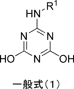
R1が少なくとも-NHC(=O)-を含む置換基を有するフェニル基、ベンゾイミダゾール基、置換基を有してもよいインドール基または置換基を有してもよいピラゾール基である]
上記分散剤の一実施形態は、前記トリアジン誘導体に対する前記アミンの含有量が0.1~5モル当量である。
上記分散剤の一実施形態は、前記トリアジン誘導体に対する前記アミンの含有量が0.3~2モル当量である。
上記分散剤の一実施形態は、前記トリアジン誘導体に対する前記無機塩基の含有量が0.1~1モル当量である。
本発明は、前記分散剤と、ポリマー分散剤とを含有する、分散組成物に関する。
上記分散組成物の一実施形態は、前記ポリマー分散剤が水酸基を有する。
上記分散組成物の一実施形態は、ポリビニルアルコール系樹脂および/またはセルロース系樹脂である。
本発明は、前記分散剤と、炭素材料と、溶剤とを含有する、分散組成物に関する。
本発明は、前記分散剤組成物と、炭素材料と、溶剤とを含有する、分散組成物に関する。
上記分散組成物の一実施形態は、更に、バインダーを含有する。
本発明は、上記分散組成物が、更に、活物質を含有する、電池用分散組成物に関する。
上記電池用分散組成物の一実施形態は、前記トリアジン誘導体と、アミンまたは無機塩基とを含む分散剤の含有量が、前記活物質表面積1m2に対して0.1~200mgである。
本発明は、集電体上に、上記電池用分散組成物より形成されてなる合剤層を備える、電極に関する。
本発明は、上記電極と、非水電解液とを備える、電池に関する。
上記電池の一実施形態は、前記非電解液1mlに対する、前記トリアジン誘導体と、アミンまたは無機塩基とを含む分散剤の含有量が、10μg~60mgである。
本発明によれば、良好な分散性で電子抵抗を低減する分散剤、当該分散剤を用い、イオン抵抗や反応抵抗を低減し、優れた特性の電池を提供することができる。
以下、本発明に係る分散剤、分散剤組成物、電池用分散組成物、電極、および電池について、順に詳細に説明する。
なお、本発明において「(メタ)アクリル」とは、「アクリル」又は「メタクリル」の各々を表す。
なお、本発明において「(メタ)アクリル」とは、「アクリル」又は「メタクリル」の各々を表す。
<分散剤>
本発明に係る分散剤は、下記一般式(1)で表されるトリアジン誘導体と、アミンまたは無機塩基とを含むこと特徴とする。
本発明に係る分散剤は、下記一般式(1)で表されるトリアジン誘導体と、アミンまたは無機塩基とを含むこと特徴とする。
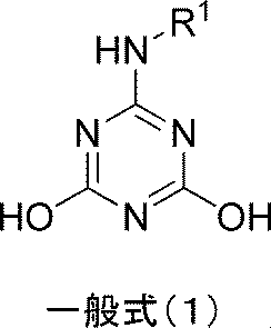
R1が少なくとも-NHC(=O)-を含む置換基を有するフェニル基、ベンゾイミダゾール基、置換基を有してもよいインドール基または置換基を有してもよいピラゾール基である]
なお、以下において「分散剤」とは、特に断りの無い限り、上記の分散剤を表し、ポリマー分散剤とは区別されるものである。
本発明者らは、上記一般式(1)で表される特定の構造を有するトリアジン誘導体と、アミンまたは無機塩基とを含む分散剤を使用した分散組成物が、良好な導電パス形成によって電子抵抗を低減させるだけでなく、イオン抵抗および反応抵抗をも低減できることを見出し、本発明を完成させた。
本発明により、従来公知の分散組成物を用いた場合よりも、イオン抵抗と反応抵抗が低く、レート特性や低温特性に優れた電池の製造が可能となる。
さらに、一般式(1)で表されるトリアジン誘導体と、アミンまたは無機塩基とを含む分散剤は、溶解性が低いため電解液への溶出が抑制される。この理由は、ひとつのトリアジン環に対して-NH-R1と水酸基が2つ直結した水素結合性が高い構造によって、結晶性が高くなり溶解性が抑えられたことによると考えられる。また、水素結合などの強い相互作用を起こしやすいことから、炭素材料に対しても作用しやすく、分散液に対する溶解性が低くても十分な分散性を発揮できるものと考えられる。
本発明により、従来公知の分散組成物を用いた場合よりも、イオン抵抗と反応抵抗が低く、レート特性や低温特性に優れた電池の製造が可能となる。
さらに、一般式(1)で表されるトリアジン誘導体と、アミンまたは無機塩基とを含む分散剤は、溶解性が低いため電解液への溶出が抑制される。この理由は、ひとつのトリアジン環に対して-NH-R1と水酸基が2つ直結した水素結合性が高い構造によって、結晶性が高くなり溶解性が抑えられたことによると考えられる。また、水素結合などの強い相互作用を起こしやすいことから、炭素材料に対しても作用しやすく、分散液に対する溶解性が低くても十分な分散性を発揮できるものと考えられる。
上記一般式(1)中、R1は、
-X1-Y1で表される基であって、X1が置換基を有してもよいアリーレン基、Y1がスルホ基又はカルボキシル基であるか、または、
少なくとも-NHC(=O)-を含む置換基を有するフェニル基、ベンゾイミダゾール基、置換基を有してもよいインドール基または置換基を有してもよいピラゾール基である。
-X1-Y1で表される基であって、X1が置換基を有してもよいアリーレン基、Y1がスルホ基又はカルボキシル基であるか、または、
少なくとも-NHC(=O)-を含む置換基を有するフェニル基、ベンゾイミダゾール基、置換基を有してもよいインドール基または置換基を有してもよいピラゾール基である。
X1の置換基を有してもよいアリーレン基の「置換基」は、同一でも異なっても良く、その具体例としては、スルホ基、カルボキシル基、ヒドロキシル基、フッ素、塩素、臭素などのハロゲン基、ニトロ基、アルキル基、アルコキシル基等を挙げることができる。また、これらの置換基は、複数あっても良い。
置換基を有してもよいアリーレン基の「アリーレン基」は、フェニレン基、ナフチレン基等が挙げられる。
R1の-NHC(=O)-を含む置換基としては、以下の構造が挙げられる。ただし、*印はベンゼン環との結合部分を表す。

また、少なくとも-NHC(=O)-を含む置換基を有するフェニル基は、その他の置換基として、メチル基、トリフルオロメチル基、メトキシ基、エトキシ基、フッ素、塩素などのハロゲン基等を有していてもよい。また、これらの置換基は、複数あってもよい。
R1の置換基を有してもよいインドール基または置換基を有してもよいピラゾール基の置換基としては、メチル基が挙げられる。
さらに、トリアジン誘導体とともに添加するアミンとしては、炭素数1~40の1級、2級、3級アルキルアミンが挙げられる。
炭素数1~40の1級アルキルアミンとしては、プロピルアミン、ブチルアミン、イソブチルアミン、オクチルアミン、2ーエチルヘキシルアミン、ラウリルアミン、ステアリルアミン、オレイルアミン、2-アミノエタノール、3-アミノプロパノール、3-エトキシプロピルアミン、3-ラウリルオキシプロピルアミン等が挙げられる。
炭素数1~40の2級アルキルアミンとしては、ジブチルアミン、ジイソブチルアミン、N-メチルヘキシルアミン、ジオクチルアミン、ジステアリルアミン、2-メチルアミノエタノール等が挙げられる。
炭素数1~40の3級アルキルアミンとしては、トリエチルアミン、トリブチルアミン、N,N-ジメチルブチルアミン、N,N-ジイソプロピルエチルアミン、ジメチルオクチルアミン、トリオクチルアミン、ジメチルデシルアミン、ジメチルラウリルアミン、ジメチルミリスチルアミン、ジメチルパルミチルアミン、ジメチルステアリルアミン、ジラウリルモノメチルアミン、トリエタノールアミン、2-(ジメチルアミノ)エタノール等が挙げられる。
この内、炭素数1~30の1級、2級または3級アルキルアミンが好ましく、炭素数1~20の1級、2級または3級アルキルアミンがさらに好ましい。
本発明で使用されるアミンの添加量は、特に限定されるものではないが、一般式(1)で表わされるトリアジン誘導体に対して、0.1モル当量以上、5モル当量以下が好ましく、0.3モル当量以上、2モル当量以下がより好ましい。
アミンは、分散剤製造時および/または電池用組成物製造時に添加することができる。
トリアジン誘導体とともに添加する無機塩基としては、アルカリ金属の水酸化物、アルカリ土類金属の水酸化物、アルカリ金属の炭酸塩、アルカリ土類金属の炭酸塩、アルカリ金属のリン酸塩、アルカリ土類金属のリン酸塩等が挙げられる。
アルカリ金属の水酸化物としては、水酸化リチウム、水酸化ナトリウム、水酸化カリウム等が挙げられる。
アルカリ土類金属の水酸化物としては、水酸化マグネシウム、水酸化カルシウム、水酸化ストロンチウム、水酸化バリウム等が挙げられる。
アルカリ金属の炭酸塩としては、炭酸リチウム、炭酸ナトリウム、炭酸水素ナトリウム、炭酸カリウム、炭酸水素カリウム等が挙げられる。
アルカリ土類金属の炭酸塩としては、炭酸マグネシウム、炭酸カルシウム、炭酸ストロンチウム、炭酸バリウム等が挙げられる。
アルカリ金属のリン酸塩としては、リン酸リチウム、リン酸三ナトリウム、リン酸水素二ナトリウム、リン酸三カリウム、リン酸水素二カリウム等が挙げられる。
アルカリ土類金属のリン酸塩としては、リン酸マグネシウム、リン酸カルシウム、リン酸ストロンチウム、リン酸バリウム等が挙げられる。
本発明で使用される無機塩基の添加量は、特に限定されるものではないが、一般式(1)で表わされるトリアジン誘導体1モルに対して、0.1モル以上、1.0モル以下が好ましく、0.3モル以上、0.7モル以下がより好ましい。
無機塩基は、分散剤製造時および/または電池用組成物製造時に添加することができる。
本発明の分散剤は、特に電池やコンデンサー、キャパシター用途で使用されるカーボンブラック等の炭素材料の分散剤として好適に使用することができるが、各種インキ、塗料、カラーフィルターレジスト等の着色組成物に使用される顔料の分散剤としても使用可能である。
[分散剤組成物]
本発明の分散剤組成物は、前記分散剤と、ポリマー分散剤とを含有することを特徴とする。
本発明者らは、前記一般式(1)で表されるトリアジン誘導体を含む分散剤と、ポリマー分散剤とを併用すると、炭素材料同士、炭素材料と活物質や集電体との密着性(剥離強度)が特異的に向上する相乗効果が得られることを見出した。また、それによって長期的に充放電を繰り返した際の電極の剥がれや劣化を抑えることができ、サイクル特性を向上させることを見出した。また、一般式(1)で表されるトリアジン誘導体とポリマー分散剤を使用した電池用分散組成物は、良好な導電パス形成によって電子抵抗を低減させるだけでなく、イオン抵抗および反応抵抗をも低減できることを見出した。
また、ポリマー分散剤を併用することにより、成膜性や膜強度の調整、またはレオロジーコントロールをすることができる。
本発明の分散剤組成物は、前記分散剤と、ポリマー分散剤とを含有することを特徴とする。
本発明者らは、前記一般式(1)で表されるトリアジン誘導体を含む分散剤と、ポリマー分散剤とを併用すると、炭素材料同士、炭素材料と活物質や集電体との密着性(剥離強度)が特異的に向上する相乗効果が得られることを見出した。また、それによって長期的に充放電を繰り返した際の電極の剥がれや劣化を抑えることができ、サイクル特性を向上させることを見出した。また、一般式(1)で表されるトリアジン誘導体とポリマー分散剤を使用した電池用分散組成物は、良好な導電パス形成によって電子抵抗を低減させるだけでなく、イオン抵抗および反応抵抗をも低減できることを見出した。
また、ポリマー分散剤を併用することにより、成膜性や膜強度の調整、またはレオロジーコントロールをすることができる。
<ポリマー分散剤>
本発明で用いるポリマー分散剤は、ポリビニルアルコール、水酸基以外の官能基、例えば、アセチル基、スルホ基、カルボキシル基、カルボニル基、アミノ基を有する変性ポリビニルアルコール、各種塩によって変性されたもの、その他アニオンまたはカチオン変性されたもの、アルデヒド類によってアセタール変性(アセトアセタール変性またはブチラール変性等)されたポリビニルアルコール系樹脂や、各種(メタ)アクリル系ポリマー、エチレン性不飽和炭化水素由来のポリマー、各種セルロース系樹脂等や、これらのコポリマーが使用できるが、これらに限定されるものではない。本発明においてポリマー分散剤は、中でも、ポリビニルアルコール系樹脂および/またはセルロース系樹脂であることが好ましい。ポリマー分散剤は1種単独で、または2種以上を組み合わせて用いることができる。
本発明で用いるポリマー分散剤は、ポリビニルアルコール、水酸基以外の官能基、例えば、アセチル基、スルホ基、カルボキシル基、カルボニル基、アミノ基を有する変性ポリビニルアルコール、各種塩によって変性されたもの、その他アニオンまたはカチオン変性されたもの、アルデヒド類によってアセタール変性(アセトアセタール変性またはブチラール変性等)されたポリビニルアルコール系樹脂や、各種(メタ)アクリル系ポリマー、エチレン性不飽和炭化水素由来のポリマー、各種セルロース系樹脂等や、これらのコポリマーが使用できるが、これらに限定されるものではない。本発明においてポリマー分散剤は、中でも、ポリビニルアルコール系樹脂および/またはセルロース系樹脂であることが好ましい。ポリマー分散剤は1種単独で、または2種以上を組み合わせて用いることができる。
また、本発明においてポリマー分散剤は、中でも、水酸基を有することが好ましい。上述した分散剤とポリマー分散剤との組み合わせの効果は、特に、ポリマー分散剤が水酸基を有する場合に顕著であった。この原理は定かではないが、ポリマー分散剤との間に水素結合などの強い分子間力が作用したことによると考えられた。
ポリマー分散剤の平均重合度は、低すぎると分散質への吸着力が弱く、高すぎると粘性が悪くなるだけでなく分散液中でうまく広がらず分散安定化効果が薄くなるため、50~3000のものが好ましく、100~2000のものが特に好ましく、200~1000のものがさらに好ましい。
ポリビニルアルコール系樹脂としては、分散質や分散溶剤、電解液と適度な親和性を持たせるために、水酸基が60mol%以上のものが好ましく、70mol%以上のものがより好ましく、75mol%以上のものがさらに好ましい。
上記水酸基量の範囲に含まれる市販のポリビニルアルコール系樹脂としては、例えば、クラレポバール(クラレ社製ポリビニルアルコール樹脂)やゴーセノール、ゴーセネックス(日本合成化学工業社製ポリビニルアルコール樹脂)、デンカポバール(デンカ社製ポリビニルアルコール樹脂)、J-ポバール(日本酢ビ・ポバール社製ポリビニルアルコール樹脂)などの商品名で、種々のグレードを入手することが出来る。また、各種官能基を有する変性ポリビニルアルコールも同様に入手できる。
市販品を使用せず合成して用いる場合には、一般に、メタノール溶液中等で酢酸ビニルを所定の重合度まで重合し、得られたポリ酢酸ビニルに水酸化ナトリウム等のアルカリ触媒を加えてけん化反応させることで、水酸基量をコントロールしたポリビニルアルコールが得られることが知られている。
変性ポリビニルアルコールを合成して用いる場合には、一般に、メタノール溶液中等で酢酸ビニルとともに(メタ)アクリル酸等の(メタ)アクリル系モノマーや、ビニルエステル系モノマー、α‐β不飽和結合と官能基を有するモノマーなどを共重合させてから、けん化反応させることで、変性率をコントロールした変性ポリビニルアルコールが得られることが知られている。また、ポリビニルアルコール系樹脂に対して酸無水物を付加反応させたり、エステル化反応させる等して変性ポリビニルアルコール系樹脂を得ることもできる。
市販のポリビニルアセタール樹脂としては、例えば、モビタール(クラレ社製ポリビニルブチラール樹脂)、エスレック(積水化学工業社製ポリビニルアセタール、またはポリビニルブチラール)などの商品名で、種々のグレードを入手することができるが、上記の好ましい水酸基量を得るために合成して用いてもよい。一般的な合成方法としては、ポリビニルアルコールにアルデヒドを反応させることで、所定のアセタール化度にコントロールしたポリビニルアセタール樹脂を得ることができる。また、アルデヒドの炭素数を変更すればアセタール基の炭素数を任意に選択することができる。
セルロース系樹脂としては、セルロースまたは、セルロースの水酸基の一部がアルキル基やヒドロキシアルキル基、カルボキシアルキル基に変性されたものやその塩を用いることができ、例えば、メトローズ(信越化学工業社製メチルセルロース、またはヒドロキシプロピルメチルセルロース)、メセロース(巴工業社製水溶性セルロースエーテル、ヒドロキシエチルメチルセルロース、ヒドロキシプロピルメチルセルロース、メチルセルロース)、サンローズ(日本製紙社製カルボシメチルセルロースナトリウム)、エトセル(ダウケミカル社製エチルセルロース)、ダイセルCMC(ダイセルファインケム社製カルボシメチルセルロースナトリウム)などの商品名で、種々のグレードを入手することができる。特に、電解液への溶解性や膨潤性の観点から、メチルセルロースやエチルセルロースなどのアルキルセルロースが好ましい。
[分散組成物]
本発明の分散組成物は、前記分散剤、又は、前記分散剤組成物と、炭素材料と、溶剤とを含有することを特徴とする。
本発明の分散組成物は、前記分散剤、又は、前記分散剤組成物と、炭素材料と、溶剤とを含有することを特徴とする。
本発明で使用される炭素材料は、特に限定されるものではないが、電池用の炭素材料として使用する場合、グラファイト、カーボンブラック、カーボンナノチューブ、カーボンナノファイバー、カーボンファイバー、グラフェン、フラーレン等を単独で、もしくは2種類以上併せて使用することが好ましい。炭素材料として用いる場合、導電性、入手の容易さ、およびコスト面から、カーボンブラックの使用が好ましい。
本発明に用いられるカーボンブラックとしては、市販のファーネスブラック、チャンネルブラック、サーマルブラック、アセチレンブラック、ケッチェンブラックなど各種のものを単独で、もしくは2種類以上併せて使用することができる。また、通常行われている酸化処理されたカーボンブラックや、中空カーボン等も使用できる。また、カーボンブラクの粒径は、0.01~1μmが好ましく、0.01~0.2μmがより好ましい。ここでいう粒径とは、電子顕微鏡で測定された平均一次粒子径を示し、この物性値は一般にカーボンブラックの物理的特性を表すのに用いられている。
本発明に用いられるカーボンナノチューブは、グラフェンを筒状に巻いた形状を有する炭素材料であり、電子顕微鏡で観察して求めた直径は数nmから100nm程度で、長さは数nmから1mm程度である。半導体特性、塗膜の透明性等を発揮するには、直径50nm以下、特に20nm以下が好ましい。長さは100nmから1mmが好ましく、特に500nmから1mmが好ましい。カーボンナノチューブには単層のものや多層構造になったものがあるが、いずれの構造であってもよい。また、カーボンナノファイバーとして分類される、電子顕微鏡で観察して求めた繊維径が100nmから1μm程度のものについても使用可能である。
本発明に用いられるグラフェンは、グラファイトを構成する単原子薄膜で、炭素原子が平面上で蜂の巣格子(六角形)状に並んだ炭素材料であり、これが積層化した多層グラフェンを含む。多層グラフェンとしては、グラフェン層数2から50層のものが使用可能である。
<溶剤>
本発明に使用する溶剤としては、非プロトン性の極性溶剤、水溶性の極性溶剤、水の内1種類を単独で用いても、2種類以上を混合して用いてもよい。非プロトン性の極性溶剤としては、アミド系溶剤が好ましく、特に、N,N-ジメチルホルムアミド、N,N-ジエチルホルムアミド、N,N-ジメチルアセトアミド、N,N-ジエチルアセトアミド、N-メチル-2-ピロリドン、ヘキサメチルリン酸トリアミド等のアミド系非プロトン性溶剤の使用が好ましい。水溶性の極性溶剤としては、アルコール系、エステル系、エーテル系、グリコール系、グリコールエステル系、グリコールエーテル系が好ましい。水は単独で用いてもよいし、炭素材料の濡れ性や塗工性向上のために、表面張力が低い水溶性の極性溶剤を少量併用してもよく、特に、プロピレングリコールモノエチルエーテル、エチレングリコールジメチルエーテル、ジエチレングリコールメチルエチルエーテル、ジプロピレングリコールジメチルエーテル、プロピレングリコールモノプロピルエーテル、N-メチル-2-ピロリドンとの併用が好ましい。
本発明に使用する溶剤としては、非プロトン性の極性溶剤、水溶性の極性溶剤、水の内1種類を単独で用いても、2種類以上を混合して用いてもよい。非プロトン性の極性溶剤としては、アミド系溶剤が好ましく、特に、N,N-ジメチルホルムアミド、N,N-ジエチルホルムアミド、N,N-ジメチルアセトアミド、N,N-ジエチルアセトアミド、N-メチル-2-ピロリドン、ヘキサメチルリン酸トリアミド等のアミド系非プロトン性溶剤の使用が好ましい。水溶性の極性溶剤としては、アルコール系、エステル系、エーテル系、グリコール系、グリコールエステル系、グリコールエーテル系が好ましい。水は単独で用いてもよいし、炭素材料の濡れ性や塗工性向上のために、表面張力が低い水溶性の極性溶剤を少量併用してもよく、特に、プロピレングリコールモノエチルエーテル、エチレングリコールジメチルエーテル、ジエチレングリコールメチルエチルエーテル、ジプロピレングリコールジメチルエーテル、プロピレングリコールモノプロピルエーテル、N-メチル-2-ピロリドンとの併用が好ましい。
<バインダー>
本発明の分散組成物は、更に、バインダーを含有してもよい。使用するバインダーとしては特に限定されないが、エチレン、プロピレン、塩化ビニル、酢酸ビニル、ビニルアルコール、マレイン酸、アクリル酸、アクリル酸エステル、メタクリル酸、メタクリル酸エステル、アクリロニトリル、スチレン、ビニルブチラール、ビニルアセタール、ビニルピロリドン等を構成単位として含む重合体または共重合体、ポリウレタン樹脂、ポリエステル樹脂、フェノール樹脂、エポキシ樹脂、フェノキシ樹脂、尿素樹脂、メラミン樹脂、アルキッド樹脂、アクリル樹脂、ホルムアルデヒド樹脂、シリコン樹脂、フッ素樹脂、カルボキシメチルセルロースのようなセルロース樹脂、スチレン-ブタジエンゴム、フッ素ゴムのようなゴム類、ポリアニリン、ポリアセチレンのような導電性樹脂等が挙げられる。また、これらの樹脂の変性体および共重合体でも良い。特に、電池用途で使用する場合には、耐性面から分子内にフッ素原子を含む高分子化合物、例えば、ポリフッ化ビニリデン、ポリフッ化ビニル、テトラフルオロエチレン等の使用が好ましい。これらバインダーは、1種または複数を組み合わせて使用することもできる。また、溶剤に水を用いる場合には、これらフッ素原子を含む高分子化合物やスチレン-ブタジエンゴムなどのエマルションと、増粘剤としても機能するカルボキシメチルセルロースとの併用が好ましい。
本発明の分散組成物は、更に、バインダーを含有してもよい。使用するバインダーとしては特に限定されないが、エチレン、プロピレン、塩化ビニル、酢酸ビニル、ビニルアルコール、マレイン酸、アクリル酸、アクリル酸エステル、メタクリル酸、メタクリル酸エステル、アクリロニトリル、スチレン、ビニルブチラール、ビニルアセタール、ビニルピロリドン等を構成単位として含む重合体または共重合体、ポリウレタン樹脂、ポリエステル樹脂、フェノール樹脂、エポキシ樹脂、フェノキシ樹脂、尿素樹脂、メラミン樹脂、アルキッド樹脂、アクリル樹脂、ホルムアルデヒド樹脂、シリコン樹脂、フッ素樹脂、カルボキシメチルセルロースのようなセルロース樹脂、スチレン-ブタジエンゴム、フッ素ゴムのようなゴム類、ポリアニリン、ポリアセチレンのような導電性樹脂等が挙げられる。また、これらの樹脂の変性体および共重合体でも良い。特に、電池用途で使用する場合には、耐性面から分子内にフッ素原子を含む高分子化合物、例えば、ポリフッ化ビニリデン、ポリフッ化ビニル、テトラフルオロエチレン等の使用が好ましい。これらバインダーは、1種または複数を組み合わせて使用することもできる。また、溶剤に水を用いる場合には、これらフッ素原子を含む高分子化合物やスチレン-ブタジエンゴムなどのエマルションと、増粘剤としても機能するカルボキシメチルセルロースとの併用が好ましい。
本発明の分散組成物は、上記分散剤、炭素材料、溶剤を含む炭素材料分散液、または、さらにバインダーを含む炭素材料分散ワニスであり、均質で良好な塗膜物性が求められる印刷インキ、塗料、プラスチック、トナー、カラーフィルタレジストインキ、電池等の分野に使用することができる。特に、均質で良好な塗膜物性と、表面抵抗の低い電極層に適した塗膜を提供することができるため、電池の電極を形成する用途で好適に使用することができる。集電体と合剤層との間に設ける下地層に用いても良い。
<分散組成物の製造方法>
本発明の分散組成物である炭素材料分散液は、上記分散剤又は分散剤組成物と、炭素材料と、溶剤とを混合することにより製造することができる。また、炭素材料分散ワニスは、上記分散剤又は分散剤組成物と、炭素材料と、溶剤と、バインダーとを混合することにより製造することができる。各成分の添加順序などについては限定されるものではなく、例えば、炭素材料分散液は、(1)全成分を一括に混合・分散する方法、(2)予め分散剤又は分散剤組成物を分散・溶解した溶剤に炭素材料を分散させる方法等が挙げられる。また、炭素材料分散ワニスは、(1)全成分を一括に混合・分散・溶解する方法、(2)予め炭素材料分散液を作製した後に、バインダー粉を混合・溶解する方法、(3)予め炭素材料分散液を作製した後に、バインダー溶液を混合する方法等が挙げられる。また、必要に応じて上記に記載の溶剤を更に追加しても良い。
本発明の分散組成物である炭素材料分散液は、上記分散剤又は分散剤組成物と、炭素材料と、溶剤とを混合することにより製造することができる。また、炭素材料分散ワニスは、上記分散剤又は分散剤組成物と、炭素材料と、溶剤と、バインダーとを混合することにより製造することができる。各成分の添加順序などについては限定されるものではなく、例えば、炭素材料分散液は、(1)全成分を一括に混合・分散する方法、(2)予め分散剤又は分散剤組成物を分散・溶解した溶剤に炭素材料を分散させる方法等が挙げられる。また、炭素材料分散ワニスは、(1)全成分を一括に混合・分散・溶解する方法、(2)予め炭素材料分散液を作製した後に、バインダー粉を混合・溶解する方法、(3)予め炭素材料分散液を作製した後に、バインダー溶液を混合する方法等が挙げられる。また、必要に応じて上記に記載の溶剤を更に追加しても良い。
混合・分散・溶解装置としては、顔料分散等に通常用いられている分散機を使用することができる。例えば、ディスパー、ホモミキサー、プラネタリーミキサー等のミキサー類、ホモジナイザー(エム・テクニック社製「クレアミックス」、PRIMIX社「フィルミックス」等、シルバーソン社製「アブラミックス」等)類、ペイントコンディショナー(レッドデビル社製)、コロイドミル(PUC社製「PUCコロイドミル」、IKA社製「コロイドミルMK」)類、コーンミル(IKA社製「コーンミルMKO」等)、ボールミル、サンドミル(シンマルエンタープライゼス社製「ダイノミル」等)、アトライター、パールミル(アイリッヒ社製「DCPミル」等)、コボールミル等のメディア型分散機、湿式ジェットミル(ジーナス社製「ジーナスPY」、スギノマシン社製「スターバースト」、ナノマイザー社製「ナノマイザー」等)、エム・テクニック社製「クレアSS-5」、奈良機械社製「MICROS」等のメディアレス分散機、その他ロールミル等が挙げられるが、これらに限定されるものではない。
また、分散機としては、分散機からの金属混入防止処理を施したものを用いることが好ましい。金属混入防止処理としては、例えばメディア型分散機を使用する場合は、アジテーターおよびベッセルがセラミック製または樹脂製の分散機を使用する方法や、金属製アジテーターおよびベッセル表面をタングステンカーバイド溶射や樹脂コーティング等の処理をした分散機を用いることが好ましい。メディアとしては、ガラスビーズまたはジルコニアビーズもしくはアルミナビーズ等のセラミックビーズを用いることが好ましい。また、ロールミルを使用する場合についても、セラミック製ロールを用いることが好ましい。分散機は、1種のみを使用してもよく、複数種の装置を組み合わせて使用してもよい。
[電池用分散組成物]
本発明の電池用分散組成物は、前記分散組成物が更に活物質を含有するものである。
本発明の電池用分散組成物は、前記分散組成物が更に活物質を含有するものである。
<活物質>
活物質は、電池内において、酸化還元反応を伴って蓄電または放電を行う物質である。正極に用いられる正極活物質と、負極に用いられる負極活物質が挙げられる。
活物質は、電池内において、酸化還元反応を伴って蓄電または放電を行う物質である。正極に用いられる正極活物質と、負極に用いられる負極活物質が挙げられる。
(正極活物質)
使用する正極活物質は、電池用活物質として機能するものであれば、特に限定はされない。例えば、リチウムイオン二次電池に使用する場合には、リチウムイオンをドーピングまたはインターカレーション可能な金属酸化物、金属硫化物等の金属化合物、および導電性高分子等を使用することができる。
使用する正極活物質は、電池用活物質として機能するものであれば、特に限定はされない。例えば、リチウムイオン二次電池に使用する場合には、リチウムイオンをドーピングまたはインターカレーション可能な金属酸化物、金属硫化物等の金属化合物、および導電性高分子等を使用することができる。
具体的には、リチウムマンガン複合酸化物(例えばLixMn2O4またはLixMnO2)、リチウムニッケル複合酸化物(例えばLixNiO2)、リチウムコバルト複合酸化物(LixCoO2)、リチウムニッケルコバルト複合酸化物(例えばLixNi1-yCoyO2)、リチウムマンガンコバルト複合酸化物(例えばLixMnyCo1-yO2)、リチウムニッケルマンガンコバルト複合酸化物(例えばLixNiyCozMn1-y-zO2)、スピネル型リチウムマンガンニッケル複合酸化物(例えばLixMn2-yNiyO4)等のリチウムと遷移金属との複合酸化物粉末、オリビン構造を有するリチウムリン酸化物粉末(例えばLixFePO4、LixFe1-yMnyPO4、LixCoPO4など)、酸化マンガン、酸化鉄、酸化銅、酸化ニッケル、バナジウム酸化物(例えばV2O5、V6O13)、酸化チタン等の遷移金属酸化物粉末、硫酸鉄(Fe2(SO4)3)、TiS2、およびFeS等の遷移金属硫化物粉末等が挙げられる。ただし、x、y、zは数であり、0<x<1、0<y<1、0<z<1、0<y+z<1である。また、ポリアニリン、ポリアセチレン、ポリピロール、ポリチオフェン等の導電性ポリマーを使用することもできる。これら正極活物質は、1種または複数を組み合わせて使用することもできる。
(負極活物質)
使用する負極活物質としては特に限定はされないが、リチウムイオンをドーピングまたはインターカレーション可能な金属Li、またはその合金、スズ合金、シリコン合金負極、LiXTiO2、LiXFe2O3、LiXFe3O4、LiXWO2等の金属酸化物系、ポリアセチレン、ポリ-p-フェニレン等の導電性高分子、ソフトカーボンやハードカーボンといったアモルファス系炭素質材料や、高黒鉛化炭素材料等の人造黒鉛、あるいは天然黒鉛等の炭素質粉末、カーボンブラック、メソフェーズカーボンブラック、樹脂焼成炭素材料、気層成長炭素繊維、炭素繊維などの炭素系材料が用いられる。ただし、xは数であり、0<x<1である。これら負極活物質は、1種または複数を組み合わせて使用することもできる。
使用する負極活物質としては特に限定はされないが、リチウムイオンをドーピングまたはインターカレーション可能な金属Li、またはその合金、スズ合金、シリコン合金負極、LiXTiO2、LiXFe2O3、LiXFe3O4、LiXWO2等の金属酸化物系、ポリアセチレン、ポリ-p-フェニレン等の導電性高分子、ソフトカーボンやハードカーボンといったアモルファス系炭素質材料や、高黒鉛化炭素材料等の人造黒鉛、あるいは天然黒鉛等の炭素質粉末、カーボンブラック、メソフェーズカーボンブラック、樹脂焼成炭素材料、気層成長炭素繊維、炭素繊維などの炭素系材料が用いられる。ただし、xは数であり、0<x<1である。これら負極活物質は、1種または複数を組み合わせて使用することもできる。
電池用分散組成物において、前記分散剤の含有量は、活物質表面積1m2に対して0.1~200mgが好ましく、0.2~100mgがより好ましく、0.5~50mgがさらに好ましい。
本発明の電池用分散組成物は、上記電池用組成物、および炭素材料、溶剤を含む炭素材料分散液、または、さらにバインダーを含む炭素材料分散ワニスであり、均質で良好な塗膜物性が求められる印刷インキ、塗料、プラスチック、トナー、カラーフィルタレジストインキ、電池等の分野に使用することができる。特に、均質で良好な塗膜物性と、表面抵抗の低い電極層に適した塗膜を提供することができるため、電池の電極を形成する用途で好適に使用することができる。集電体と合剤層との間に設ける下地層に用いてもよい。
電池用分散組成物は、上記分散剤又は分散剤組成物、炭素材料、溶剤、バインダーを含む電池用分散組成物に、活物質を含有させた電池用分散組成物(以下、「合剤ペースト」と云う)として使用することが好ましい。
この合剤ペーストは、上記分散剤と、炭素材料と、溶剤と、バインダーと、活物質とを混合することにより製造することができる。各成分の添加順序などについては限定されるものではなく、例えば、全成分を一括に混合する方法、上述の方法で予め作製した炭素材料分散液に残りの成分を投入して混合する方法、上述の方法で予め作製した炭素材料分散ワニスに活物質を投入して混合する方法等が挙げられる。また、必要に応じて上記に記載の溶剤を更に追加しても良い。
合剤ペーストを製造するための装置としては、上述した分散組成物を製造する際に用いられるものと同様のものを使用することができる。
[電極、及び電池]
本発明に係る電極は、集電体上に、前記電池用分散組成物より形成されてなる合剤層を備えることを特徴とする。
また、本発明に係る電池は、前記電極と、非水電解液とを備えることを特徴とする。
本発明に係る電極は、集電体上に、前記電池用分散組成物より形成されてなる合剤層を備えることを特徴とする。
また、本発明に係る電池は、前記電極と、非水電解液とを備えることを特徴とする。
前記本発明の電池用分散組成物は、特にリチウムイオン二次電池に好適に使用することができる。以下では一例としてリチウムイオン二次電池について説明するが、前記電池用分散組成物を用いた電池はリチウムイオン二次電池に限定されるものではない。
リチウムイオン二次電池は、集電体上に正極合剤層を有する正極電極と、集電体上に負極合剤層を有する負極電極と、リチウムを含む電解質からなる非水電解液とを具備する。
電極について、使用する集電体の材質や形状は特に限定されず、材質としては、アルミニウム、銅、ニッケル、チタン、ステンレス等の金属や合金が用いられるが、特に正極材料としてはアルミニウムが、負極材料としては銅の使用が好ましい。また、形状としては、一般的には平板上の箔が用いられるが、表面を粗面化したものや、穴あき箔状のもの、およびメッシュ状のものも使用できる。また、集電体には、集電体と合剤層との接触抵抗や密着性を向上させる目的で、導電性の下地層を設けても良い。
合剤層は、集電体上に上記の合剤ペーストを直接塗布し、乾燥することで形成できる。合剤層の厚みとしては、一般的には1μm以上、1mm以下であり、好ましくは100μm以上、500μm以下である。塗布方法については特に制限はなく、公知の方法を用いることができる。具体的には、ダイコーティング法、ディップコーティング法、ロールコーティング法、ドクターコーティング法、スプレーコティング法、グラビアコーティング法、スクリーン印刷法、静電塗装法等が挙げられる。また、塗布後に平版プレスやカレンダーロール等による圧延処理を行っても良い。
本発明の電池において、非電解液1mlに対する、前記分散剤の含有量が、10μg~60mgが好ましく、50μg~20mgがより好ましく、70μg~15mgがさらに好ましい。
リチウムイオン二次電池を構成する電解液としては、リチウムを含んだ電解質を非水系の溶剤に溶解したものを用いる。電解質としては、LiBF4、LiClO4、LiPF6、LiAsF6、LiSbF6、LiCF3SO3、Li(CF3SO2)2N、LiC4F9SO3、Li(CF3SO2)3C、LiI、LiBr、LiCl、LiAlCl、LiHF2、LiSCN、LiBPh4(ただし、Phはフェニル基である。)等が挙げられるがこれらに限定されない。
非水系の溶剤としては特に限定はされないが、エチレンカーボネート、プロピレンカーボネート、ブチレンカーボネート、ジメチルカーボネート、エチルメチルカーボネート、ジエチルカーボネート等のカーボネート類、γ-ブチロラクトン、γ-バレロラクトン、γ-オクタノイックラクトン等のラクトン類、テトラヒドロフラン、2-メチルテトラヒドロフラン、1,3-ジオキソラン、4-メチル-1,3-ジオキソラン、1,2-メトキシエタン、1,2-エトキシエタン、1,2-ジブトキシエタン等のグライム類、メチルフォルメート、メチルアセテート、メチルプロピオネート等のエステル類、ジメチルスルホキシド、スルホラン等のスルホキシド類、アセトニトリル等のニトリル類、N-メチル-2-ピロリドン等が挙げられる。またこれらの溶剤は、それぞれ単独で使用しても良いが、2種以上を混合して使用しても良い。特に、高誘電率で電解質の溶解力が高いエチレンカーボネートとその他溶剤との混合が好ましく、さらに、その他溶剤としてはプロピレンカーボネート、ブチレンカーボネート、ジメチルカーボネート、エチルメチルカーボネートジエチルカーボネート等の直線状のカーボネート系溶剤がより好ましい。
更に上記電解液を、ポリマーマトリクスに保持しゲル状とした高分子電解質とすることもできる。ポリマーマトリクスとしては、ポリアルキレンオキシドセグメントを有するアクリレート系樹脂、ポリアルキレンオキシドセグメントを有するポリホスファゼン系樹脂、ポリアルキレンオキシドセグメントを有するポリシロキサン等が挙げられるがこれらに限定されない。
本発明の電池の構造については特に限定されないが、通常、正極および負極と、必要に応じて設けられるセパレーターとから構成され、ペーパー型、円筒型、角型、ボタン型、積層型、巻回型など、使用する目的に応じた種々の形状とすることができる。
[他の実施形態]
前記一般式(1)で表されるトリアジン誘導体が酸性官能基を有する場合、前記ポリマー分散剤と組み合わせることにより、アミンまたは無機塩基を有しない場合でも、分散剤として用いることができる。即ち、分散剤組成物の一実施形態として、前記一般式(1)で表される酸性官能基を有するトリアジン誘導体と、ポリマー分散剤とを含んでなる分散剤組成物であってもよい。この場合、一般式(1)中の、R1は、-X1-Y1で表される基であり、X1は置換基を有してもよいアリーレン基を表し、Y1はスルホ基またはカルボキシル基を表す。
前記本発明の各構成において、前記本発明の分散剤組成物に代えて、本実施形態の分散剤組成物を使用することができる。
前記一般式(1)で表されるトリアジン誘導体が酸性官能基を有する場合、前記ポリマー分散剤と組み合わせることにより、アミンまたは無機塩基を有しない場合でも、分散剤として用いることができる。即ち、分散剤組成物の一実施形態として、前記一般式(1)で表される酸性官能基を有するトリアジン誘導体と、ポリマー分散剤とを含んでなる分散剤組成物であってもよい。この場合、一般式(1)中の、R1は、-X1-Y1で表される基であり、X1は置換基を有してもよいアリーレン基を表し、Y1はスルホ基またはカルボキシル基を表す。
前記本発明の各構成において、前記本発明の分散剤組成物に代えて、本実施形態の分散剤組成物を使用することができる。
以下、実施例に基づき本発明を詳細に説明するが、本発明はその要旨を超えない限り、以下の実施例に限定されるものではない。また、個々の組成物の違いを明確にするために、分散剤、炭素材料、溶剤からなる分散組成物を「炭素材料分散液」、分散剤、炭素材料、溶剤、バインダーからなる分散組成物を「炭素材料分散ワニス」、分散剤、炭素材料、溶剤、バインダー、活物質からなる電池用分散組成物を「合剤ペースト」ということがある。また、特に断わりの無い限り、溶剤として使用したN-メチル-2-ピロリドンを「NMP」、質量%を「%」と略記する。
以下、3つの実施例群に分けて説明する。各実施例群はそれぞれ独立のものであり、実施例群間で異なる分散剤に同一の略号が付されることがある。
分散剤以外の材料は、3つの実施例群で共通しているため、以下に記載し、各実施例群内での記載は省略する。
以下、3つの実施例群に分けて説明する。各実施例群はそれぞれ独立のものであり、実施例群間で異なる分散剤に同一の略号が付されることがある。
分散剤以外の材料は、3つの実施例群で共通しているため、以下に記載し、各実施例群内での記載は省略する。
<炭素材料>
デンカブラックHS100(デンカ社製):アセチレンブラック、電子顕微鏡で観察して求めた平均一次粒子径が48nm、窒素吸着量からS-BET式で求めた比表面積が39m2/g、以下「HS100」と略記する。
super-P(TIMCAL社製):ファーネスブラック、電子顕微鏡で観察して求めた平均一次粒子径が40nm、窒素吸着量からS-BET式で求めた比表面積が62m2/g。
モナーク800(キャボット社製):ファーネスブラック、電子顕微鏡で観察して求めた平均一次粒子径が17nm、窒素吸着量からS-BET式で求めた比表面積が210m2/g、以下「M800」と略記する。
EC-300J(ライオン・スペシャリティ・ケミカルズ社製):ケッチェンブラック、電子顕微鏡で観察して求めた平均一次粒子径が40nm、窒素吸着量からS-BET式で求めた比表面積が800m2/g。
カーボンナノチューブ:多層カーボンナノチューブ、電子顕微鏡で観察して求めた繊維径10nm、繊維長2~5μm、窒素吸着量からS-BET式で求めた比表面積が600m2/g、以下CNTと略記する。
VGCF(昭和電工社製):カーボンナノファイバー、電子顕微鏡で観察して求めた繊維径150nm、繊維長10~20μm。
デンカブラックHS100(デンカ社製):アセチレンブラック、電子顕微鏡で観察して求めた平均一次粒子径が48nm、窒素吸着量からS-BET式で求めた比表面積が39m2/g、以下「HS100」と略記する。
super-P(TIMCAL社製):ファーネスブラック、電子顕微鏡で観察して求めた平均一次粒子径が40nm、窒素吸着量からS-BET式で求めた比表面積が62m2/g。
モナーク800(キャボット社製):ファーネスブラック、電子顕微鏡で観察して求めた平均一次粒子径が17nm、窒素吸着量からS-BET式で求めた比表面積が210m2/g、以下「M800」と略記する。
EC-300J(ライオン・スペシャリティ・ケミカルズ社製):ケッチェンブラック、電子顕微鏡で観察して求めた平均一次粒子径が40nm、窒素吸着量からS-BET式で求めた比表面積が800m2/g。
カーボンナノチューブ:多層カーボンナノチューブ、電子顕微鏡で観察して求めた繊維径10nm、繊維長2~5μm、窒素吸着量からS-BET式で求めた比表面積が600m2/g、以下CNTと略記する。
VGCF(昭和電工社製):カーボンナノファイバー、電子顕微鏡で観察して求めた繊維径150nm、繊維長10~20μm。
<バインダー>
KFポリマーW1100(クレハ社製):ポリフッ化ビニリデン(PVDF)、以下PVDFと略記する。
ポリテトラフッ化エチレンエマルション:(三井・デュポンフロロケミカル社製)、以下PTFEと略記する。
カルボキシメチルセルロース(日本製紙社製):以下CMCと略記する。
KFポリマーW1100(クレハ社製):ポリフッ化ビニリデン(PVDF)、以下PVDFと略記する。
ポリテトラフッ化エチレンエマルション:(三井・デュポンフロロケミカル社製)、以下PTFEと略記する。
カルボキシメチルセルロース(日本製紙社製):以下CMCと略記する。
<正極活物質>
LiNi1/3Mn1/3Co1/3O2(戸田工業社製):正極活物質、ニッケルマンガンコバルト酸リチウム、電子顕微鏡で観察して求めた平均一次粒子径が5.0μm、窒素吸着量からS-BET式で求めた比表面積が0.62m2/g、以下、NMCと略記する。
HLC-22(本荘ケミカル社製):正極活物質、コバルト酸リチウム(LiCoO2)、電子顕微鏡で観察して求めた平均一次粒子径が6.6μm、窒素吸着量からS-BET式で求めた比表面積が0.62m2/g、以下LCOと略記する。
LiNi0.8Co0.15Al0.05O2(住友金属社製):正極活物質、ニッケルコバルトアルミ酸リチウム、電子顕微鏡で観察して求めた平均一次粒子径が5.8μm、窒素吸着量からS-BET式で求めた比表面積が0.38m2/g、以下、NCAと略記する。
LiFePO4(クラリアント社製):正極活物質、リン酸鉄リチウム、電子顕微鏡で観察して求めた平均一次粒子径が0.4μm、窒素吸着量からS-BET式で求めた比表面積が15.3m2/g、以下、LFPと略記する。
LiNi1/3Mn1/3Co1/3O2(戸田工業社製):正極活物質、ニッケルマンガンコバルト酸リチウム、電子顕微鏡で観察して求めた平均一次粒子径が5.0μm、窒素吸着量からS-BET式で求めた比表面積が0.62m2/g、以下、NMCと略記する。
HLC-22(本荘ケミカル社製):正極活物質、コバルト酸リチウム(LiCoO2)、電子顕微鏡で観察して求めた平均一次粒子径が6.6μm、窒素吸着量からS-BET式で求めた比表面積が0.62m2/g、以下LCOと略記する。
LiNi0.8Co0.15Al0.05O2(住友金属社製):正極活物質、ニッケルコバルトアルミ酸リチウム、電子顕微鏡で観察して求めた平均一次粒子径が5.8μm、窒素吸着量からS-BET式で求めた比表面積が0.38m2/g、以下、NCAと略記する。
LiFePO4(クラリアント社製):正極活物質、リン酸鉄リチウム、電子顕微鏡で観察して求めた平均一次粒子径が0.4μm、窒素吸着量からS-BET式で求めた比表面積が15.3m2/g、以下、LFPと略記する。
<負極活物質>
球状黒鉛(日本黒鉛社製):負極活物質、電子顕微鏡で観察して求めた一次粒子径が15μm、窒素吸着量からS-BET式で求めた比表面積が1.0m2/g、以下球状黒鉛と略記する。
球状黒鉛(日本黒鉛社製):負極活物質、電子顕微鏡で観察して求めた一次粒子径が15μm、窒素吸着量からS-BET式で求めた比表面積が1.0m2/g、以下球状黒鉛と略記する。
<ポリマー分散剤>
PVA-103(クラレ社製):ポリビニルアルコール、けん化度98.0~99.0mol%、平均重合度300
PVA-403(クラレ社製):ポリビニルアルコール、けん化度78.5~81.5mol%、平均重合度300
KL-506(クラレ社製):アニオン変性ポリビニルアルコール、けん化度74.0~80.0mol%、重合度600
ゴーセネックスL-3266(日本合成化学社製):スルホン酸変性ポリビニルアルコール、けん化度86.5~89.0mol%(以下、L-3266と略記する)
ゴーセネックスK-434(日本合成化学社製):カチオン変性ポリビニルアルコール、けん化度85.5~88.0mol%(以下、K-434と略記する)
ポリビニルブチラールA: ポリビニルブチラール、ブチラール化度15mol%、水酸基量84mol%、酢酸基1mol%、重合度300(以下、PVB-Aと略記する)メトローズSM-15(信越化学社製):メチルセルロース、置換度1.8、20℃における2%水溶液の粘度約15mPa・s、(以下、SM-15と略記する)
エトセル-10(ダウケミカル社製):エチルセルロース、25℃における5%トルエン/エタノール(8/2)溶液の粘度9.0~11.0mPa・s
PVA-103(クラレ社製):ポリビニルアルコール、けん化度98.0~99.0mol%、平均重合度300
PVA-403(クラレ社製):ポリビニルアルコール、けん化度78.5~81.5mol%、平均重合度300
KL-506(クラレ社製):アニオン変性ポリビニルアルコール、けん化度74.0~80.0mol%、重合度600
ゴーセネックスL-3266(日本合成化学社製):スルホン酸変性ポリビニルアルコール、けん化度86.5~89.0mol%(以下、L-3266と略記する)
ゴーセネックスK-434(日本合成化学社製):カチオン変性ポリビニルアルコール、けん化度85.5~88.0mol%(以下、K-434と略記する)
ポリビニルブチラールA: ポリビニルブチラール、ブチラール化度15mol%、水酸基量84mol%、酢酸基1mol%、重合度300(以下、PVB-Aと略記する)メトローズSM-15(信越化学社製):メチルセルロース、置換度1.8、20℃における2%水溶液の粘度約15mPa・s、(以下、SM-15と略記する)
エトセル-10(ダウケミカル社製):エチルセルロース、25℃における5%トルエン/エタノール(8/2)溶液の粘度9.0~11.0mPa・s
(合成例)PVB-Aの合成
PVA-103の10%水溶液を調製し、水溶液100質量部に対し、塩酸0.2質量部、ブチルアルデヒド2質量部を撹拌しながら滴下した。続いて80℃に昇温して1時間保持した後放冷した。これを乾燥、粉砕してアセタール化度15mol%のPVB-Aを得た。
PVA-103の10%水溶液を調製し、水溶液100質量部に対し、塩酸0.2質量部、ブチルアルデヒド2質量部を撹拌しながら滴下した。続いて80℃に昇温して1時間保持した後放冷した。これを乾燥、粉砕してアセタール化度15mol%のPVB-Aを得た。
[第1実施例群]
第1実施例群では、一般式(1)で表されるトリアジン誘導体のうち、R1が-X1-Y1で表される基であって、X1が置換基を有してもよいアリーレン基、Y1がスルホ基又はカルボキシル基であるものについて取り扱う。
第1実施例群では、一般式(1)で表されるトリアジン誘導体のうち、R1が-X1-Y1で表される基であって、X1が置換基を有してもよいアリーレン基、Y1がスルホ基又はカルボキシル基であるものについて取り扱う。
<分散剤>
以下に本発明の一般式(1)で表わされるトリアジン誘導体A~Tの構造を示す。本発明に用いる一般式(1)で表わされるトリアジン誘導体A~Tの製造方法としては、特に限定されるものではなく、周知の方法を適用することができる。例えば、特開2004-217842号公報等に記載されている方法を適用することができる。上記公報による開示を参照することにより、本明細書の一部に組み込むものとする。
以下に本発明の一般式(1)で表わされるトリアジン誘導体A~Tの構造を示す。本発明に用いる一般式(1)で表わされるトリアジン誘導体A~Tの製造方法としては、特に限定されるものではなく、周知の方法を適用することができる。例えば、特開2004-217842号公報等に記載されている方法を適用することができる。上記公報による開示を参照することにより、本明細書の一部に組み込むものとする。
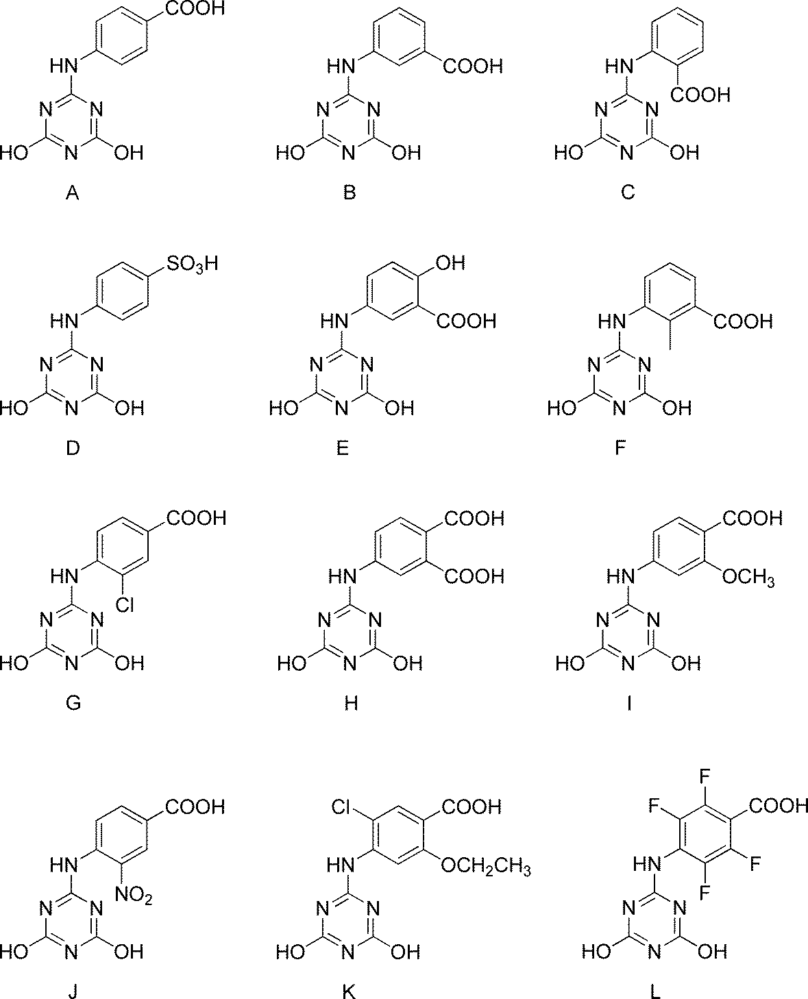
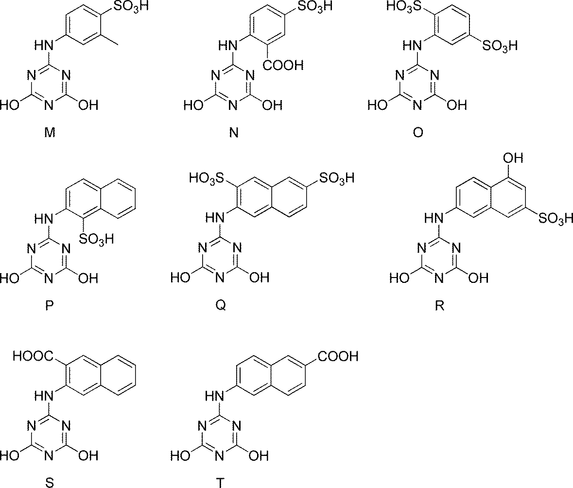
<トリアジン誘導体とアミンからなる分散剤の製造方法>
以下の実施例に記載した方法で表1記載の分散剤a~ajを製造した。
以下の実施例に記載した方法で表1記載の分散剤a~ajを製造した。

[実施例A1-1]
(分散剤aの製造)
水200gにトリアジン誘導体Aを0.040モル加えた。これにオクチルアミンを0.040モル加え、60℃で2時間撹拌した。室温まで冷却後、ろ過精製を行った。得られた残渣を90℃で48時間乾燥することにより、分散剤aを得た。
(分散剤aの製造)
水200gにトリアジン誘導体Aを0.040モル加えた。これにオクチルアミンを0.040モル加え、60℃で2時間撹拌した。室温まで冷却後、ろ過精製を行った。得られた残渣を90℃で48時間乾燥することにより、分散剤aを得た。
[実施例A1-2]~[実施例A1-20]
(分散剤b~分散剤tの製造)
分散剤aの製造においてトリアジン誘導体Aの代わりに表1の実施例A1-2~実施例A1-20に記載のトリアジン誘導体B~トリアジン誘導体Tを添加した以外は、実施例A1-1と同様な方法で製造し、分散剤b~分散剤tを得た。
(分散剤b~分散剤tの製造)
分散剤aの製造においてトリアジン誘導体Aの代わりに表1の実施例A1-2~実施例A1-20に記載のトリアジン誘導体B~トリアジン誘導体Tを添加した以外は、実施例A1-1と同様な方法で製造し、分散剤b~分散剤tを得た。
[実施例A1-21]~[実施例A1-31]
(分散剤u~分散剤aeの製造)
分散剤bの製造においてオクチルアミンの代わりに表1の実施例A1-21~実施例A1-31に記載のアミンを添加した以外は、実施例A1-2と同様な方法で製造し、分散剤u~分散剤aeを得た。
(分散剤u~分散剤aeの製造)
分散剤bの製造においてオクチルアミンの代わりに表1の実施例A1-21~実施例A1-31に記載のアミンを添加した以外は、実施例A1-2と同様な方法で製造し、分散剤u~分散剤aeを得た。
[実施例A1-32]~[実施例A1-36]
(分散剤af~分散剤ajの製造)
分散剤bの製造においてオクチルアミンの添加量を表1の実施例A1-32~実施例A1-36に記載の添加量に変更した以外は実施例A1-2と同様な方法で製造し、分散剤af~分散剤ajを得た。
(分散剤af~分散剤ajの製造)
分散剤bの製造においてオクチルアミンの添加量を表1の実施例A1-32~実施例A1-36に記載の添加量に変更した以外は実施例A1-2と同様な方法で製造し、分散剤af~分散剤ajを得た。
以下に比較例で使用するトリアジン誘導体U~Wの構造を示す。比較例に用いるトリアジン誘導体U~Wの製造方法としては、特に限定されるものではなく、周知の方法を適用することができる。例えば、特開2004-217842号公報等に記載されている方法を適用することができる。上記公報による開示を参照することにより、本明細書の一部に組み込むものとする。

以下の比較例に記載した方法で表2記載の分散剤ak~amを製造した。

[比較例A1-1]~[比較例A1-3]
(分散剤ak~分散剤amの製造)
分散剤aの製造においてトリアジン誘導体Aの代わりに表2の比較例A1-1~比較例A1-3に記載のトリアジン誘導体U~トリアジン誘導体Wを添加した以外は、実施例A1-1と同様な方法で製造し、分散剤ak~分散剤amを得た。
(分散剤ak~分散剤amの製造)
分散剤aの製造においてトリアジン誘導体Aの代わりに表2の比較例A1-1~比較例A1-3に記載のトリアジン誘導体U~トリアジン誘導体Wを添加した以外は、実施例A1-1と同様な方法で製造し、分散剤ak~分散剤amを得た。
[実施例A2-1]
<炭素材料分散液の調製>
表3に示す組成に従い、ガラス瓶にN-メチル-2-ピロリドンと分散剤aを仕込み、混合した後、炭素材料を加え、ジルコニアビーズをメディアとして、ペイントコンディショナーで2時間分散し、分散剤aを含む炭素材料分散液を得た。
<炭素材料分散液の調製>
表3に示す組成に従い、ガラス瓶にN-メチル-2-ピロリドンと分散剤aを仕込み、混合した後、炭素材料を加え、ジルコニアビーズをメディアとして、ペイントコンディショナーで2時間分散し、分散剤aを含む炭素材料分散液を得た。
<炭素材料分散ワニスの調製>
表4に示す組成に従い、調製した分散剤aを含む種炭素材料分散液とバインダー、N-メチル-2-ピロリドンをディスパーにて混合し、炭素材料分散ワニスを得た。
表4に示す組成に従い、調製した分散剤aを含む種炭素材料分散液とバインダー、N-メチル-2-ピロリドンをディスパーにて混合し、炭素材料分散ワニスを得た。
<合剤ペーストの調製>
表5に示す組成に従い、調製した分散剤aを含む種炭素材料分散ワニスと活物質、N-メチル-2-ピロリドンをディスパーにて混合し、正極合剤ペーストを得た。
表5に示す組成に従い、調製した分散剤aを含む種炭素材料分散ワニスと活物質、N-メチル-2-ピロリドンをディスパーにて混合し、正極合剤ペーストを得た。
<電極の作製>
調製した分散剤aを含む正極合剤ペーストを、厚さ20μmのアルミ箔上にドクターブレードを用いて塗工した後、減圧下120℃で30分間乾燥し、ローラープレス機にて圧延処理し、塗布量17mg/cm2、密度3.0g/cm3の電極を作製した。厚みや密度が均一な電極が得られた。
調製した分散剤aを含む正極合剤ペーストを、厚さ20μmのアルミ箔上にドクターブレードを用いて塗工した後、減圧下120℃で30分間乾燥し、ローラープレス機にて圧延処理し、塗布量17mg/cm2、密度3.0g/cm3の電極を作製した。厚みや密度が均一な電極が得られた。
<リチウムイオン二次電池正極評価用セルの組み立て>
作製した分散剤aを含む電極を直径16mmに打ち抜き正極とし、金属リチウム箔(厚さ0.15mm)を負極として、正極および負極の間に多孔質ポリプロピレンフィルムからなるセパレーター(厚さ20μm、空孔率50%)を挿入積層し、電解液(エチレンカーボネートとジエチルカーボネートを体積比1:1に混合した混合溶媒にLiPF6を1Mの濃度で溶解させた非水電解液)を0.1ml満たして二極密閉式金属セル(宝泉社製HSフラットセル)を組み立てた。セルの組み立てはアルゴンガス置換したグローブボックス内で行った。
作製した分散剤aを含む電極を直径16mmに打ち抜き正極とし、金属リチウム箔(厚さ0.15mm)を負極として、正極および負極の間に多孔質ポリプロピレンフィルムからなるセパレーター(厚さ20μm、空孔率50%)を挿入積層し、電解液(エチレンカーボネートとジエチルカーボネートを体積比1:1に混合した混合溶媒にLiPF6を1Mの濃度で溶解させた非水電解液)を0.1ml満たして二極密閉式金属セル(宝泉社製HSフラットセル)を組み立てた。セルの組み立てはアルゴンガス置換したグローブボックス内で行った。
[実施例A2-2~A2-36]分散剤種の比較-1
分散剤aを用いたかわりに、表3に示した分散剤b~ajをそれぞれ用いた以外は実施例A2-1と同様な方法で分散し、正極評価用セルを組み立てた。
分散剤aを用いたかわりに、表3に示した分散剤b~ajをそれぞれ用いた以外は実施例A2-1と同様な方法で分散し、正極評価用セルを組み立てた。
(炭素材料分散液の組成)

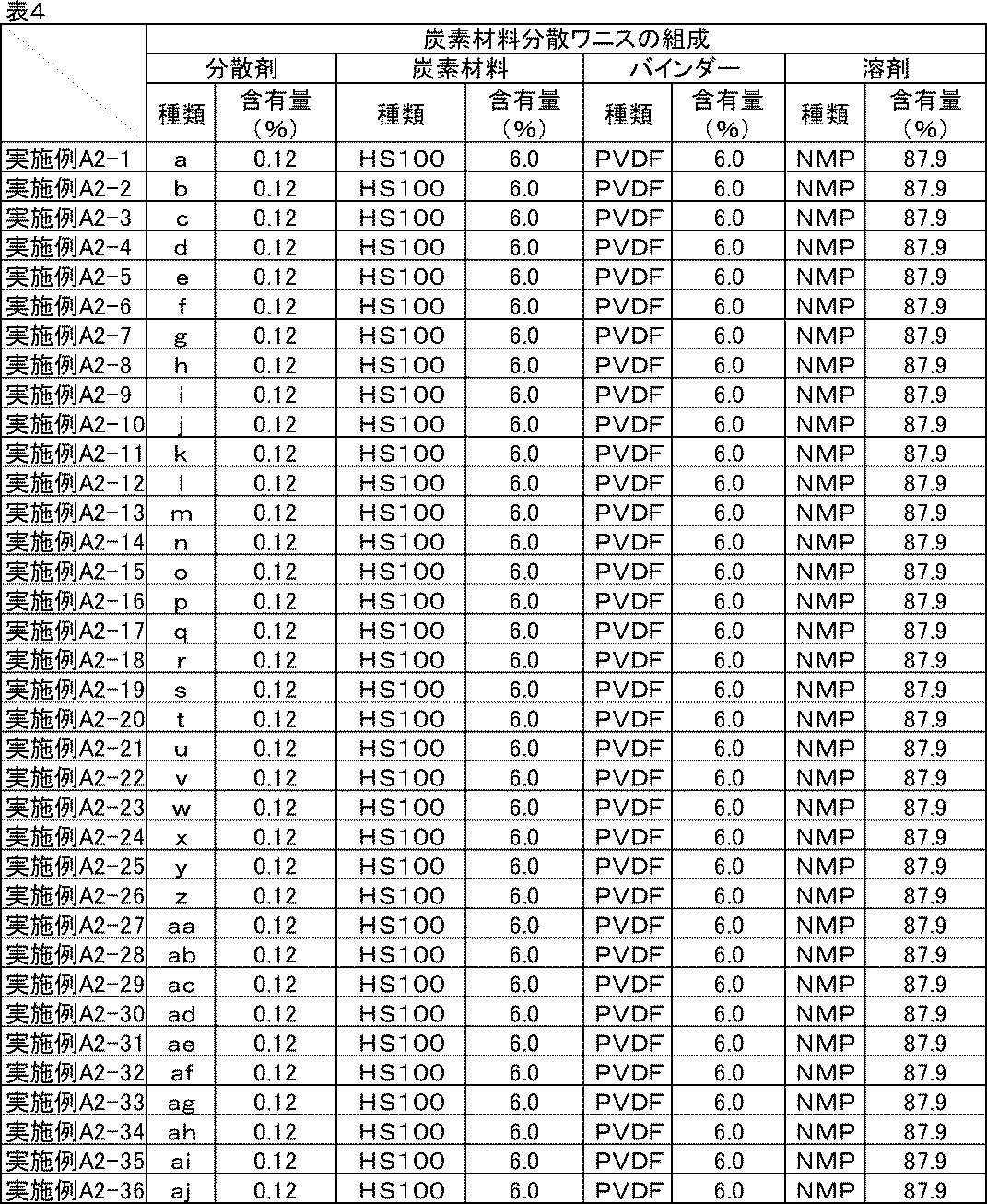
(正極合剤ペーストの組成)

[比較例A2-1~A2-4]分散剤種の比較-2
表6に示した炭素材料分散液、表7に示した炭素材料分散ワニス、表8に示した正極合剤ペーストの材料と組成に従い、実施例A2-1と同様な方法で分散し、正極評価用セルを組み立てた。比較例A2-4には分散剤を用いなかった。
表6に示した炭素材料分散液、表7に示した炭素材料分散ワニス、表8に示した正極合剤ペーストの材料と組成に従い、実施例A2-1と同様な方法で分散し、正極評価用セルを組み立てた。比較例A2-4には分散剤を用いなかった。
(炭素材料分散液の組成)
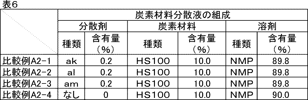
(炭素材料分散ワニスの組成)
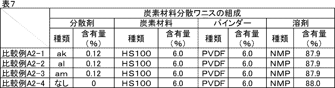
(正極合剤ペーストの組成)

<イオン抵抗評価>
実施例A2-1~A2-36、比較例A2-1~A2-4で組み立てた正極評価用セルを-20℃の恒温槽内で12時間静置し、開回路電位にて周波数0.1Hz、振幅10mVで交流インピーダンス測定を行い、イオン抵抗|Z|ionを求めた。続いて正極評価用セルを室温(25℃)に移して3時間静置し、同様にインピーダンス測定を行い、イオン抵抗|Z|ionを求めた。測定にはインピーダンスアナライザーを用いた。
実施例A2-1~A2-36、比較例A2-1~A2-4で組み立てた正極評価用セルを-20℃の恒温槽内で12時間静置し、開回路電位にて周波数0.1Hz、振幅10mVで交流インピーダンス測定を行い、イオン抵抗|Z|ionを求めた。続いて正極評価用セルを室温(25℃)に移して3時間静置し、同様にインピーダンス測定を行い、イオン抵抗|Z|ionを求めた。測定にはインピーダンスアナライザーを用いた。
<反応抵抗評価>
イオン抵抗評価に続いて、充放電測定装置を用い、室温にて0.1Cの定電流定電圧充電(上限電圧4.2V)で満充電とし、0.1Cの定電流で放電下限電圧3.0Vまで放電を行う充放電を1サイクルとして合計5サイクル行った。5サイクル目の0.1C放電容量を記録しておいた。次に、3.0Vまで放電した状態の正極評価用セルをインピーダンスアナライザーに接続し、3.0V、振幅10mV、周波数0.1Hzから1MHzにおいて交流インピーダンス測定を行った。結果をコールコールプロット法にて複素平面上にプロットすると、半円状の曲線が得られる。この円弧の大きさを活物質の反応抵抗|Z|reとした。
イオン抵抗評価に続いて、充放電測定装置を用い、室温にて0.1Cの定電流定電圧充電(上限電圧4.2V)で満充電とし、0.1Cの定電流で放電下限電圧3.0Vまで放電を行う充放電を1サイクルとして合計5サイクル行った。5サイクル目の0.1C放電容量を記録しておいた。次に、3.0Vまで放電した状態の正極評価用セルをインピーダンスアナライザーに接続し、3.0V、振幅10mV、周波数0.1Hzから1MHzにおいて交流インピーダンス測定を行った。結果をコールコールプロット法にて複素平面上にプロットすると、半円状の曲線が得られる。この円弧の大きさを活物質の反応抵抗|Z|reとした。
<室温レート特性・低温放電特性評価>
次に、室温にて0.1Cで同様に満充電にした後、0.5Cの定電流で放電下限電圧3.0Vまで放電し、再度0.1Cで満充電にしてから5Cの定電流で3.0Vまで放電した。反応抵抗評価の試験で記録しておいた5サイクル目の0.1C放電容量に対する5C放電容量の比率を、室温レート特性(%)とした。またここで、室温における0.5C放電容量を記録しておいた。続いて、室温、0.1Cで同様に満充電にしてから-20℃の恒温槽内に移して12時間静置した後に、0.5Cの定電流で同じく放電した。室温の0.5C放電容量に対する-20℃の0.5C放電容量の比率を、低温放電特性(%)とした。室温レート特性、低温放電特性共に100%に近いほど良好である。
次に、室温にて0.1Cで同様に満充電にした後、0.5Cの定電流で放電下限電圧3.0Vまで放電し、再度0.1Cで満充電にしてから5Cの定電流で3.0Vまで放電した。反応抵抗評価の試験で記録しておいた5サイクル目の0.1C放電容量に対する5C放電容量の比率を、室温レート特性(%)とした。またここで、室温における0.5C放電容量を記録しておいた。続いて、室温、0.1Cで同様に満充電にしてから-20℃の恒温槽内に移して12時間静置した後に、0.5Cの定電流で同じく放電した。室温の0.5C放電容量に対する-20℃の0.5C放電容量の比率を、低温放電特性(%)とした。室温レート特性、低温放電特性共に100%に近いほど良好である。
<評価結果>
実施例A2-1~A2-36、比較例A2-1、A2-2に記載の炭素材料分散液、炭素材料分散ワニス、正極合剤ペーストは良好な分散状態であり、1か月経時後も沈降や増粘はなかった。比較例A2-3の炭素材料分散液、炭素材料分散ワニス、正極合剤ペーストは初期から高粘度であり、分散性はかなり劣っていた。分散剤を用いていない比較例A2-4は初期からかなりの高粘度で流動性が悪かったが、そのまま比較用に用いた。また、1か月経時後はゲル状になっていた。
実施例A2-1~A2-36、比較例A2-1、A2-2に記載の炭素材料分散液、炭素材料分散ワニス、正極合剤ペーストは良好な分散状態であり、1か月経時後も沈降や増粘はなかった。比較例A2-3の炭素材料分散液、炭素材料分散ワニス、正極合剤ペーストは初期から高粘度であり、分散性はかなり劣っていた。分散剤を用いていない比較例A2-4は初期からかなりの高粘度で流動性が悪かったが、そのまま比較用に用いた。また、1か月経時後はゲル状になっていた。
実施例A2-1~A2-36、比較例A2-1~A2-4のイオン抵抗、反応抵抗、室温レート特性、低温放電特性の評価結果を表9に示す。

表9からわかる通り、分散剤a~ajを用いた実施例A2-1~A2-36の正極は室温および-20℃のイオン抵抗、反応抵抗、室温レート特性、低温放電特性の全てにおいて、分散剤を用いない比較例A2-4や分散剤ak~amを用いた比較例A2-1~A2-3の正極と比べて非常に優れていた。分散剤ak、alは、特に低温のイオン抵抗が高く、低温放電特性も悪かった。
分散剤a~ajは、極めて電子密度の高いLi+が近傍に存在することで、誘電分極を生じ、電池内では高い誘電率で存在していると考えられる。これによりイオン伝導度を向上させたり、活物質とLiが反応する際のLi+の脱溶媒和エネルギーや溶媒和エネルギーを低減させ、結果としてイオン抵抗および反応抵抗が小さくなって、電池全体としても特性が向上すると思われる。
[実施例A3-1~A3-5][比較例A3-1~A3-5]炭素材料種の比較
表10に示した炭素材料分散液、表11に示した炭素材料分散ワニス、表12に示した正極合剤ペーストの材料と組成に従い、実施例A2-1と同様な方法で分散し、正極評価用セルを組み立てた。高比表面積の炭素材料に対しては分散剤が多く必要であるため、それぞれの炭素材料に合わせて適宜使用量を決定した。
表10に示した炭素材料分散液、表11に示した炭素材料分散ワニス、表12に示した正極合剤ペーストの材料と組成に従い、実施例A2-1と同様な方法で分散し、正極評価用セルを組み立てた。高比表面積の炭素材料に対しては分散剤が多く必要であるため、それぞれの炭素材料に合わせて適宜使用量を決定した。
(炭素材料分散液の組成)

(炭素材料分散ワニスの組成)

(正極合剤ペーストの組成)

<評価結果>
いずれの実施例、比較例に記載の炭素材料分散液、炭素材料分散ワニス、正極合剤ペーストも良好な分散状態であり、1か月経時後も沈降や増粘はなかった。
いずれの実施例、比較例に記載の炭素材料分散液、炭素材料分散ワニス、正極合剤ペーストも良好な分散状態であり、1か月経時後も沈降や増粘はなかった。
実施例A3-1~A3-5、比較例A3-1~A3-5のイオン抵抗、反応抵抗、室温レート特性、低温放電特性の評価結果を表13に示す。
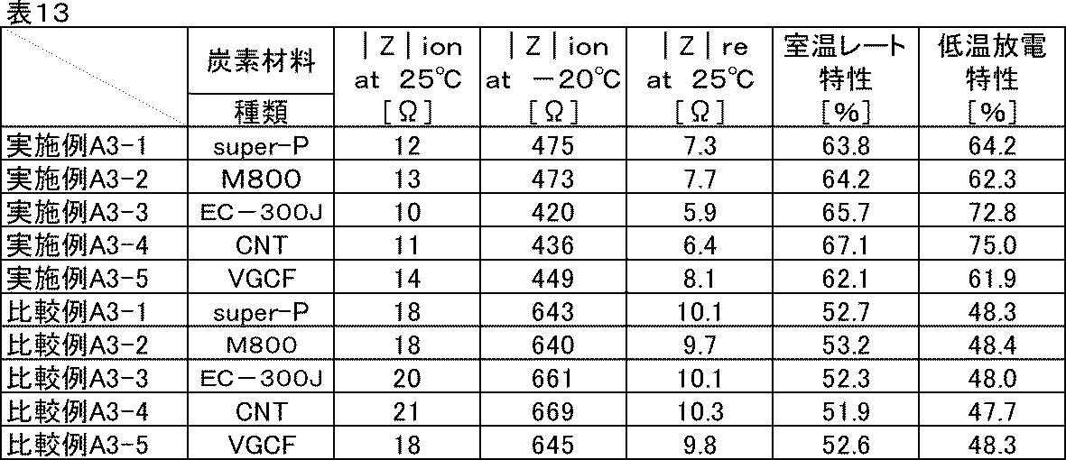
いずれの炭素材料であっても同様の効果が確認できた。実施例A3-1~A3-5の差異は炭素材料の導電性による差異であると考えられる。また、比較例A3-1~A3-5では、分散剤の添加量が多いものほど低温のイオン抵抗が高い傾向にあった。
以上の検証から、先に述べた効果は炭素材料種によらないことが確認できた。
[実施例A4-1~A4-6]活物質表面積あたりの分散剤量の比較-1
実施例A2-1の分散剤量の代わりに、表14、表15、表16に示す分散剤量とした以外は同様にして正極評価用セルを組み立てた。電極中の活物質表面積1m2に対する分散剤量(mg)を表17に示した。
実施例A2-1の分散剤量の代わりに、表14、表15、表16に示す分散剤量とした以外は同様にして正極評価用セルを組み立てた。電極中の活物質表面積1m2に対する分散剤量(mg)を表17に示した。
(炭素材料分散液の組成)

(炭素材料分散ワニスの組成)

(正極合剤ペーストの組成)
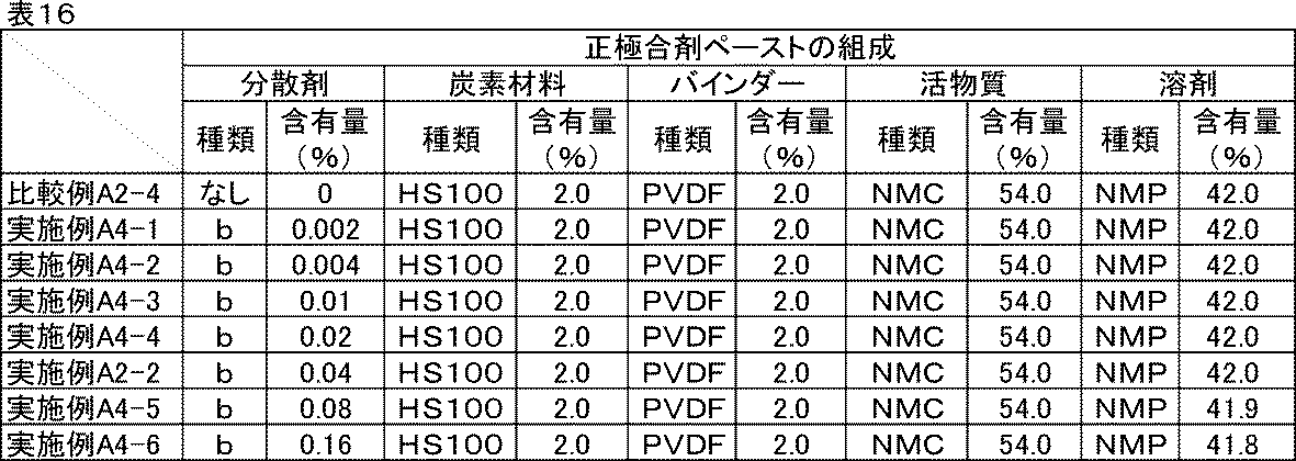
(活物質表面積あたりの分散剤量)

<評価結果>
比較例A2-4、実施例A2-2、実施例A4-1~A4-6の反応抵抗、室温レート特性、低温放電特性の評価結果を表18に示す。
比較例A2-4、実施例A2-2、実施例A4-1~A4-6の反応抵抗、室温レート特性、低温放電特性の評価結果を表18に示す。

実施例A4-1から、活物質表面積に対する分散剤量が少なすぎると効果が小さくなることがわかった。実施例A4-2の分散剤量以上で大きな効果が得られるようになり、分散剤量が増えるにつれて徐々に良化した。
[実施例A5-1~A5-8]活物質表面積あたりの分散剤量の比較-2
表19、表20、表21に示す材料、組成にて実施例A2-1と同様に分散し、正極評価用セルを作製した。電極中の活物質表面積1m2に対する分散剤量(mg)を表22に示した。
表19、表20、表21に示す材料、組成にて実施例A2-1と同様に分散し、正極評価用セルを作製した。電極中の活物質表面積1m2に対する分散剤量(mg)を表22に示した。
(炭素材料分散液の組成)

(炭素材料分散ワニスの組成)
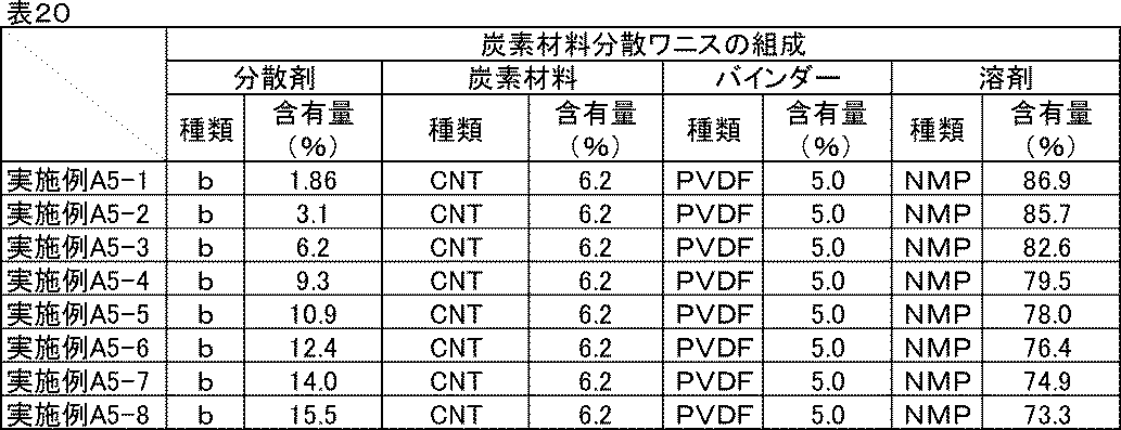
(正極合剤ペーストの組成)
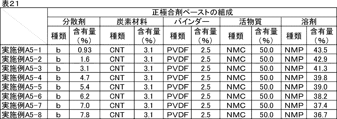
(活物質表面積あたりの分散剤量)

<評価結果>
実施例A5-1~実施例A5-8、の反応抵抗、室温レート特性、低温放電特性の評価結果を表23に示す。
実施例A5-1~実施例A5-8、の反応抵抗、室温レート特性、低温放電特性の評価結果を表23に示す。

表23より、実施例A5-6の分散剤量を超えると反応抵抗低減効果が小さくなることがわかった。分散剤量が過剰になると、脱溶媒和エネルギーの低減以上に抵抗成分としての悪影響が大きくなることによると考えられる。
以上のことから、より大きな反応抵抗低減効果を得るためには、活物質表面積に対する分散剤添加量の最適な範囲が存在することがわかった。
[実施例A6-1~A6-6]電解液量に対する分散剤量の比較-1
実施例A4-2で作製した正極を用いて、表24に示す電解液の量に変更した以外は、実施例A4-2と同様に正極評価用セルを組み立てた。
実施例A4-2で作製した正極を用いて、表24に示す電解液の量に変更した以外は、実施例A4-2と同様に正極評価用セルを組み立てた。

[実施例A7-1~A7-7]電解液量に対する分散剤量の比較-2
実施例A5-3で作製した正極合剤ペーストを用いて、塗布量を28mg/cm2に変更した以外は実施例A5-3と同様な方法で正極を作製した。さらに、正極評価用セルに添加する電解液の量を表25に示す量に変更し、それ以外は実施例A5-3と同様に正極評価用セルを組み立てた。
実施例A5-3で作製した正極合剤ペーストを用いて、塗布量を28mg/cm2に変更した以外は実施例A5-3と同様な方法で正極を作製した。さらに、正極評価用セルに添加する電解液の量を表25に示す量に変更し、それ以外は実施例A5-3と同様に正極評価用セルを組み立てた。
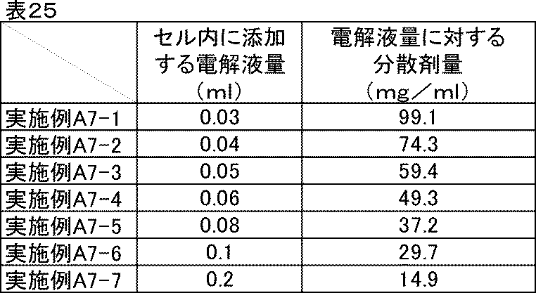
<評価結果>
実施例A4-2、実施例A6-1~A6-6、比較例A2-4のイオン抵抗、反応抵抗、室温レート特性、低温放電特性の評価結果を表26に示す。実施例A7-1~実施例A7-7のイオン抵抗、反応抵抗、室温レート特性、低温放電特性の評価結果を表27に示す。
実施例A4-2、実施例A6-1~A6-6、比較例A2-4のイオン抵抗、反応抵抗、室温レート特性、低温放電特性の評価結果を表26に示す。実施例A7-1~実施例A7-7のイオン抵抗、反応抵抗、室温レート特性、低温放電特性の評価結果を表27に示す。
実施例A4-2、実施例A6-1~A6-6の反応抵抗はいずれも同等であった。これは、活物質表面積に対する分散剤量が等しいことによると考えられる。
また、実施例A6-1~A6-4では室温および低温のイオン抵抗は低くなっており、実施例A6-4を下限に実施例A6-5、A6-6では効果が小さくなった。大きな効果を得るには、電解液量に対する分散剤最適量の下限が存在することが示された。
室温レート特性および低温放電特性はイオン抵抗と反応抵抗両方の影響を受けるため、電池として優れた特性を得るためには両方の効果が得られるよう設計するのが良い。
一方、実施例A7-1~A7-7の比較から、電解液量に対する分散剤量が多すぎてもイオン抵抗低減効果が小さくなることがわかった。これは、分散剤は絶縁性の化合物であるため、過剰にあると、それ自体が抵抗成分になってしまうことによると考えられる。
以上のことから、電解液量に対する分散剤最適量には上限も存在することがわかった。
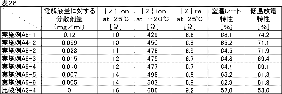
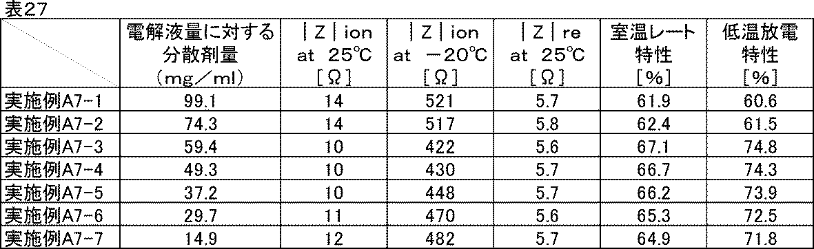
[実施例A8-1]電解液の影響調査
実施例A2-2で用いた電解液(エチレンカーボネートとジエチルカーボネートを体積比1:1に混合した混合溶媒にLiPF6を1Mの濃度で溶解させた非水電解液)の代わりに、エチレンカーボネートとジエチルカーボネートを体積比1:2に混合した混合溶媒に、LiPF6を1Mの濃度で溶解させた非水電解液を用いた以外は、実施例A2-2と同様に正極評価用セルを組み立てた。
実施例A2-2で用いた電解液(エチレンカーボネートとジエチルカーボネートを体積比1:1に混合した混合溶媒にLiPF6を1Mの濃度で溶解させた非水電解液)の代わりに、エチレンカーボネートとジエチルカーボネートを体積比1:2に混合した混合溶媒に、LiPF6を1Mの濃度で溶解させた非水電解液を用いた以外は、実施例A2-2と同様に正極評価用セルを組み立てた。
[実施例A8-2]
実施例A2-2で用いた電解液(エチレンカーボネートとジエチルカーボネートを体積比1:1に混合した混合溶媒にLiPF6を1Mの濃度で溶解させた非水電解液)の代わりに、エチレンカーボネートとエチルメチルカーボネート、ジメチルカーボネートを体積比1:1:1に混合した混合溶媒に、LiPF6を1Mの濃度で溶解させた非水電解液を用いた以外は、実施例A2-2と同様に正極評価用セルを組み立てた。
実施例A2-2で用いた電解液(エチレンカーボネートとジエチルカーボネートを体積比1:1に混合した混合溶媒にLiPF6を1Mの濃度で溶解させた非水電解液)の代わりに、エチレンカーボネートとエチルメチルカーボネート、ジメチルカーボネートを体積比1:1:1に混合した混合溶媒に、LiPF6を1Mの濃度で溶解させた非水電解液を用いた以外は、実施例A2-2と同様に正極評価用セルを組み立てた。
比較例A2-4で用いた電解液(エチレンカーボネートとジエチルカーボネートを体積比1:1に混合した混合溶媒にLiPF6を1Mの濃度で溶解させた非水電解液)の代わりに、エチレンカーボネートとジエチルカーボネートを体積比1:2に混合した混合溶媒にLiPF6を1Mの濃度で溶解させた非水電解液を用いた以外は、比較例A2-4と同様に正極評価用セルを組み立てた。
[比較例A8-2]
比較例A2-4で用いた電解液(エチレンカーボネートとジエチルカーボネートを体積比1:1に混合した混合溶媒にLiPF6を1Mの濃度で溶解させた非水電解液)の代わりに、エチレンカーボネートとエチルメチルカーボネート、ジメチルカーボネートを体積比1:1:1に混合した混合溶媒に、LiPF6を1Mの濃度で溶解させた非水電解液を用いた以外は、比較例A2-4と同様に正極評価用セルを組み立てた。
比較例A2-4で用いた電解液(エチレンカーボネートとジエチルカーボネートを体積比1:1に混合した混合溶媒にLiPF6を1Mの濃度で溶解させた非水電解液)の代わりに、エチレンカーボネートとエチルメチルカーボネート、ジメチルカーボネートを体積比1:1:1に混合した混合溶媒に、LiPF6を1Mの濃度で溶解させた非水電解液を用いた以外は、比較例A2-4と同様に正極評価用セルを組み立てた。
<評価結果>
実施例A2-2、実施例A8-1、実施例A8-2、比較例A2-4、比較例A8-1、比較例A8-2のイオン抵抗、室温レート特性、低温放電特性の評価結果を表28に示す。
実施例A2-2、実施例A8-1、実施例A8-2、比較例A2-4、比較例A8-1、比較例A8-2のイオン抵抗、室温レート特性、低温放電特性の評価結果を表28に示す。
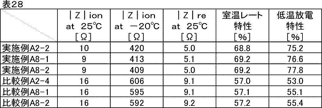
実施例A8-1、実施例A8-2より、電解液の種類によらずすべての特性が良化することが確認できた。本実施例に示した電解液以外でも、一般的に用いられる非水電解液であれば、種類によらず同じ効果が得られると思われる。
次に、活物質の種類を変更して同様に評価した。
[実施例A9-1~A9-3]活物質種の比較
実施例A2-2で用いた炭素材料分散ワニスを用いて、表29に示した活物質と組成に従って、実施例A2-2と同様な方法で分散し、正極評価用セルを組み立てた。
実施例A2-2で用いた炭素材料分散ワニスを用いて、表29に示した活物質と組成に従って、実施例A2-2と同様な方法で分散し、正極評価用セルを組み立てた。
[比較例A9-1~A9-3]
比較例A2-1で用いた炭素材料分散ワニスを用いて、表30に示した活物質と組成に従って、比較例A2-1と同様な方法で分散し、正極評価用セルを組み立てた。
比較例A2-1で用いた炭素材料分散ワニスを用いて、表30に示した活物質と組成に従って、比較例A2-1と同様な方法で分散し、正極評価用セルを組み立てた。
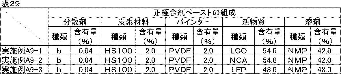
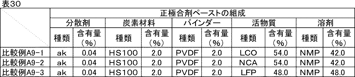
<評価結果>
実施例A9-1~A9-3、比較例A9-1~A9-3のイオン抵抗、反応抵抗、室温レート特性、低温放電特性の評価結果を表31に示す。
実施例A9-1~A9-3、比較例A9-1~A9-3のイオン抵抗、反応抵抗、室温レート特性、低温放電特性の評価結果を表31に示す。

活物質の性能によって電池の特性に差異はあるものの、同じ活物質で比較するといずれも特性が向上していることが確認できた。
続いて、負極に用いた場合の評価を行った。
[実施例A10-1]
<炭素材料分散ワニスの調製>
表32に示す組成に従い、実施例A2-1で作製した分散剤aを含む炭素材料分散液とバインダー、N-メチル-2-ピロリドンをディスパーにて混合し、炭素材料分散ワニスを得た。
<炭素材料分散ワニスの調製>
表32に示す組成に従い、実施例A2-1で作製した分散剤aを含む炭素材料分散液とバインダー、N-メチル-2-ピロリドンをディスパーにて混合し、炭素材料分散ワニスを得た。
<合剤ペーストの調製>
表33に示す組成に従い、調製した分散剤aを含む種炭素材料分散ワニスと活物質、N-メチル-2-ピロリドンをディスパーにて混合し、負極合剤ペーストを得た。
表33に示す組成に従い、調製した分散剤aを含む種炭素材料分散ワニスと活物質、N-メチル-2-ピロリドンをディスパーにて混合し、負極合剤ペーストを得た。
<電極の作製>
調製した分散剤aを含む負極合剤ペーストを、厚さ20μmの銅箔上にドクターブレードを用いて塗工した後、減圧下120℃で30分間乾燥し、ローラープレス機にて圧延処理し、塗布量15mg/cm2、密度1.8g/cm3の電極を作製した。厚みや密度が均一な電極が得られた。
調製した分散剤aを含む負極合剤ペーストを、厚さ20μmの銅箔上にドクターブレードを用いて塗工した後、減圧下120℃で30分間乾燥し、ローラープレス機にて圧延処理し、塗布量15mg/cm2、密度1.8g/cm3の電極を作製した。厚みや密度が均一な電極が得られた。
<リチウムイオン二次電池負極評価用セルの組み立て>
作製した分散剤aを含む電極を直径18mmに打ち抜き負極とし、金属リチウム箔(厚さ0.15mm)を正極として、負極および正極の間に多孔質ポリプロピレンフィルムからなるセパレーター(厚さ20μm、空孔率50%)を挿入積層し、電解液(エチレンカーボネートとジエチルカーボネートを体積比1:1に混合した混合溶媒にLiPF6を1Mの濃度で溶解させた非水電解液)を0.1ml満たして二極密閉式金属セル(宝泉社製HSフラットセル)を組み立てた。セルの組み立てはアルゴンガス置換したグローブボックス内で行った。
作製した分散剤aを含む電極を直径18mmに打ち抜き負極とし、金属リチウム箔(厚さ0.15mm)を正極として、負極および正極の間に多孔質ポリプロピレンフィルムからなるセパレーター(厚さ20μm、空孔率50%)を挿入積層し、電解液(エチレンカーボネートとジエチルカーボネートを体積比1:1に混合した混合溶媒にLiPF6を1Mの濃度で溶解させた非水電解液)を0.1ml満たして二極密閉式金属セル(宝泉社製HSフラットセル)を組み立てた。セルの組み立てはアルゴンガス置換したグローブボックス内で行った。
[実施例A10-2~A10-36]
実施例A2-2~A2-36で作製した分散剤b~分散剤ajをそれぞれ含む炭素材料分散液を用いて、表32、表33に示した材料と組成に従い、実施例A10-1と同様な方法で分散し、負極評価用セルを組み立てた。
実施例A2-2~A2-36で作製した分散剤b~分散剤ajをそれぞれ含む炭素材料分散液を用いて、表32、表33に示した材料と組成に従い、実施例A10-1と同様な方法で分散し、負極評価用セルを組み立てた。

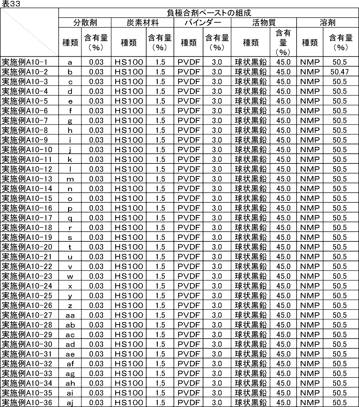
[比較例A10-1~A10-4]
比較例A2-1~A2-4で作製した炭素材料分散液を用いて、表34、表35に示した材料と組成に従い炭素材料分散ワニス、負極合剤ペーストを、実施例A10-1と同様な方法で分散し、負極評価用セルを組み立てた。比較例A10-4には分散剤を用いなかった。
比較例A2-1~A2-4で作製した炭素材料分散液を用いて、表34、表35に示した材料と組成に従い炭素材料分散ワニス、負極合剤ペーストを、実施例A10-1と同様な方法で分散し、負極評価用セルを組み立てた。比較例A10-4には分散剤を用いなかった。
(炭素材料分散ワニスの組成)

(負極合材ペーストの組成)
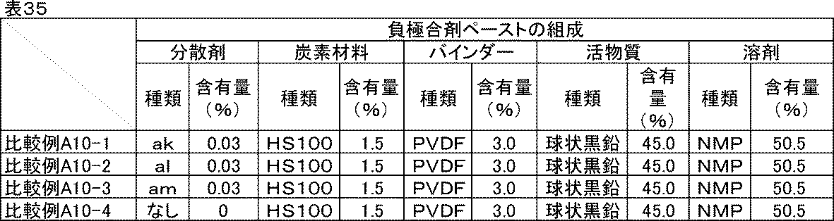
<イオン抵抗評価>
実施例A2-1と同じ条件でインピーダンス測定を行い、-20℃および室温(25℃)におけるイオン抵抗|Z|ionを求めた。
実施例A2-1と同じ条件でインピーダンス測定を行い、-20℃および室温(25℃)におけるイオン抵抗|Z|ionを求めた。
<反応抵抗評価>
イオン抵抗評価に続いて、充放電測定装置を用い、室温にて0.1Cの定電流定電圧充電(上限電圧2.0V)で満充電とし、0.1Cの定電流で放電下限電圧0.0Vまで放電を行う充放電を1サイクルとして合計5サイクル行った。5サイクル目の0.1C放電容量を記録しておいた。次に、0.0Vまで放電した状態の負極評価用セルをインピーダンスアナライザーに接続し、0.0V、振幅10mV、周波数0.1Hzから1MHzにおいて交流インピーダンス測定を行った。結果をコールコールプロット法にて複素平面上にプロットすると、半円状の曲線が得られる。この円弧の大きさを活物質の反応抵抗|Z|reとした。
イオン抵抗評価に続いて、充放電測定装置を用い、室温にて0.1Cの定電流定電圧充電(上限電圧2.0V)で満充電とし、0.1Cの定電流で放電下限電圧0.0Vまで放電を行う充放電を1サイクルとして合計5サイクル行った。5サイクル目の0.1C放電容量を記録しておいた。次に、0.0Vまで放電した状態の負極評価用セルをインピーダンスアナライザーに接続し、0.0V、振幅10mV、周波数0.1Hzから1MHzにおいて交流インピーダンス測定を行った。結果をコールコールプロット法にて複素平面上にプロットすると、半円状の曲線が得られる。この円弧の大きさを活物質の反応抵抗|Z|reとした。
<室温レート特性・低温放電特性評価>
次に、室温にて0.1Cで同様に満充電にした後、0.5Cの定電流で放電下限電圧0.0Vまで放電し、再度0.1Cで満充電にしてから5Cの定電流で0.0Vまで放電した。反応抵抗評価の試験で記録しておいた5サイクル目の0.1C放電容量に対する5Cの放電容量の比率を、室温レート特性(%)とした。またここで、室温における0.5C放電容量を記録しておいた。続いて、室温、0.1Cで同様に満充電にしてから-20℃の恒温槽内に移して12時間静置し、0.5Cの定電流で同じく放電した。室温の0.5C放電容量に対する-20℃の0.5C放電容量の比率を、低温放電特性(%)とした。
次に、室温にて0.1Cで同様に満充電にした後、0.5Cの定電流で放電下限電圧0.0Vまで放電し、再度0.1Cで満充電にしてから5Cの定電流で0.0Vまで放電した。反応抵抗評価の試験で記録しておいた5サイクル目の0.1C放電容量に対する5Cの放電容量の比率を、室温レート特性(%)とした。またここで、室温における0.5C放電容量を記録しておいた。続いて、室温、0.1Cで同様に満充電にしてから-20℃の恒温槽内に移して12時間静置し、0.5Cの定電流で同じく放電した。室温の0.5C放電容量に対する-20℃の0.5C放電容量の比率を、低温放電特性(%)とした。
<評価結果>
実施例A10-1~A10-36、比較例A10-1~A10-2に記載の炭素材料分散液、炭素材料分散ワニス、負極合剤ペーストは良好な分散状態であり、1か月経時後も沈降や増粘はなかった。比較例A10-3の炭素材料分散液、炭素材料分散ワニス、負極合剤ペーストは初期から高粘度であり、分散性はかなり劣っていた。分散剤を用いていない比較例A10-4は初期から高粘度で流動性が悪かったが、そのまま比較用に用いた。また、1か月経時後は活物質の沈降が確認された。
実施例A10-1~A10-36、比較例A10-1~A10-2に記載の炭素材料分散液、炭素材料分散ワニス、負極合剤ペーストは良好な分散状態であり、1か月経時後も沈降や増粘はなかった。比較例A10-3の炭素材料分散液、炭素材料分散ワニス、負極合剤ペーストは初期から高粘度であり、分散性はかなり劣っていた。分散剤を用いていない比較例A10-4は初期から高粘度で流動性が悪かったが、そのまま比較用に用いた。また、1か月経時後は活物質の沈降が確認された。
実施例A10-1~A10-36、比較例A10-1~A10-4のイオン抵抗、反応抵抗、室温レート特性、低温放電特性の評価結果を表36に示す。
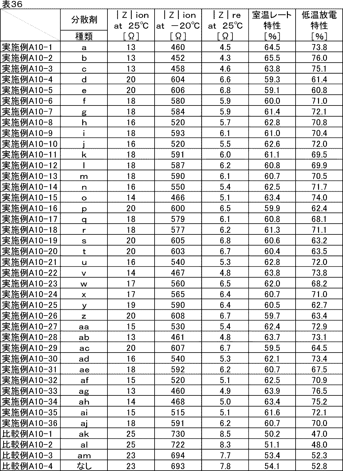
負極に用いた場合も、正極の場合と同じくイオン抵抗低減および反応抵抗低減効果が得られた。
以下の実施例に記載した方法で表37記載の分散剤水溶液wa~xeを製造した。
[実施例A11-1]
(分散剤水溶液waの製造)
水200gにトリアジン誘導体Aを0.040モル加えた。これに水酸化ナトリウムを0.040モル加え、60℃で2時間撹拌した。室温まで冷却後、トリアジン誘導体Aと水酸化ナトリウムを含む分散剤水溶液waを得た。
(分散剤水溶液waの製造)
水200gにトリアジン誘導体Aを0.040モル加えた。これに水酸化ナトリウムを0.040モル加え、60℃で2時間撹拌した。室温まで冷却後、トリアジン誘導体Aと水酸化ナトリウムを含む分散剤水溶液waを得た。
[実施例A11-2~A11-20]
(分散剤水溶液wb~wtの製造)
分散剤waの製造においてトリアジン誘導体Aの代わりに表37の実施例A11-2~A11-20に記載のトリアジン誘導体B~トリアジン誘導体Tを添加した以外は、実施例A11-1と同様な方法で製造し、分散剤水溶液wb~wtを得た。
(分散剤水溶液wb~wtの製造)
分散剤waの製造においてトリアジン誘導体Aの代わりに表37の実施例A11-2~A11-20に記載のトリアジン誘導体B~トリアジン誘導体Tを添加した以外は、実施例A11-1と同様な方法で製造し、分散剤水溶液wb~wtを得た。
[実施例A11-21~A11-26]
(分散剤水溶液wu~wzの製造)
分散剤水溶液wbの製造において水酸化ナトリウムの代わりに表37に示す無機塩基をそれぞれ添加した以外は、実施例A11-2と同様な方法で製造し、分散剤水溶液wu~wzを得た。
(分散剤水溶液wu~wzの製造)
分散剤水溶液wbの製造において水酸化ナトリウムの代わりに表37に示す無機塩基をそれぞれ添加した以外は、実施例A11-2と同様な方法で製造し、分散剤水溶液wu~wzを得た。
[実施例A11-27~A11-31]
(分散剤水溶液xa~xeの製造)
分散剤水溶液wbの製造において水酸化ナトリウムの添加量を表37の実施例A11-27~A11-31に記載の添加量に変更した以外は実施例A11-2と同様な方法で製造し、分散剤水溶液xa~xeを得た。
(分散剤水溶液xa~xeの製造)
分散剤水溶液wbの製造において水酸化ナトリウムの添加量を表37の実施例A11-27~A11-31に記載の添加量に変更した以外は実施例A11-2と同様な方法で製造し、分散剤水溶液xa~xeを得た。
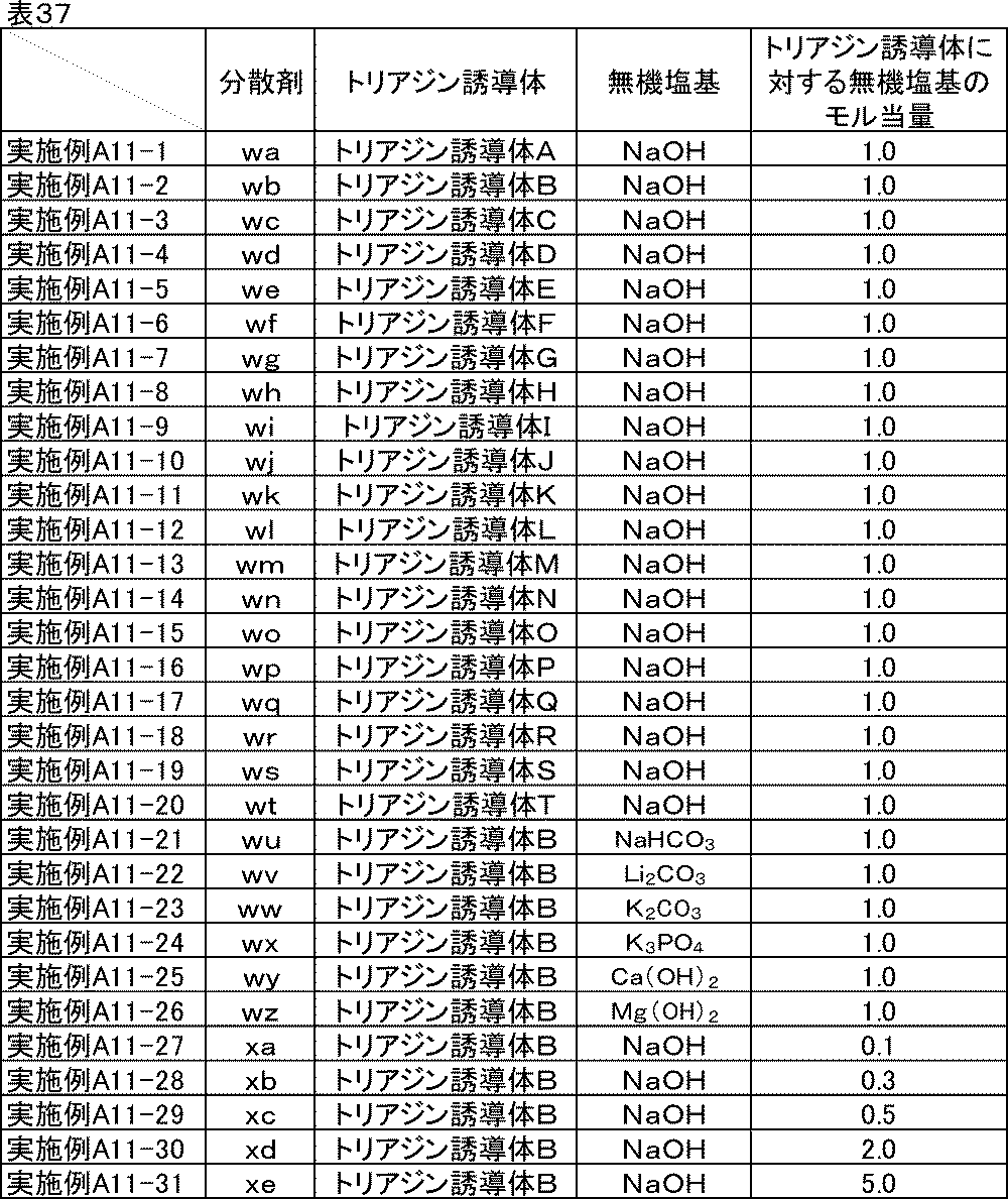
以下の比較例に記載した方法で表38記載の分散剤xf~xhを製造した。
[比較例A11-1~A11-3]
(分散剤xf~xhの製造)
分散剤waの製造においてトリアジン誘導体Aの代わりに表38の比較例A11-1~11-3に記載のトリアジン誘導体U~トリアジン誘導体Wを添加した以外は、実施例A11-1と同様な方法で製造し、分散剤xf~xhを得た。
(分散剤xf~xhの製造)
分散剤waの製造においてトリアジン誘導体Aの代わりに表38の比較例A11-1~11-3に記載のトリアジン誘導体U~トリアジン誘導体Wを添加した以外は、実施例A11-1と同様な方法で製造し、分散剤xf~xhを得た。
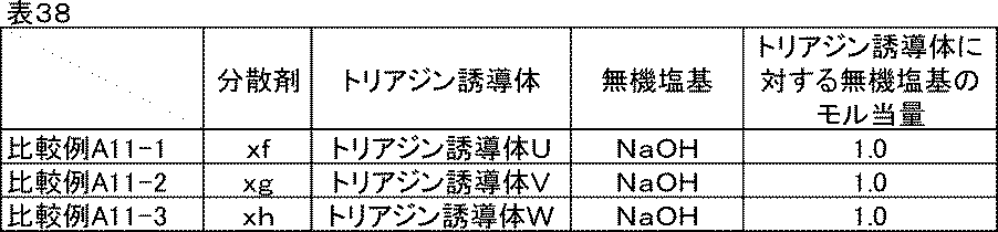
[実施例A12-1]
<炭素材料分散液の調製>
表39に示す組成に従い、ガラス瓶に水と分散剤水溶液waを仕込み、混合した後、炭素材料を加え、ジルコニアビーズをメディアとして、ペイントコンディショナーで2時間分散し、炭素材料分散液を得た。このとき、分散剤水溶液の添加量は、トリアジン誘導体AとNaOHの合計量を有効成分とし、炭素材料分散液全体に占める有効成分の割合が、表39に示す組成になるように決定した。また、分散剤水溶液に含まれる水は、そのまま炭素材料分散液の溶剤とし、不足分をさらに加えた。
<炭素材料分散液の調製>
表39に示す組成に従い、ガラス瓶に水と分散剤水溶液waを仕込み、混合した後、炭素材料を加え、ジルコニアビーズをメディアとして、ペイントコンディショナーで2時間分散し、炭素材料分散液を得た。このとき、分散剤水溶液の添加量は、トリアジン誘導体AとNaOHの合計量を有効成分とし、炭素材料分散液全体に占める有効成分の割合が、表39に示す組成になるように決定した。また、分散剤水溶液に含まれる水は、そのまま炭素材料分散液の溶剤とし、不足分をさらに加えた。
<炭素材料分散ワニスの調製>
表40に示す組成に従い、調製した炭素材料分散液とバインダー、水をディスパーにて混合し、炭素材料分散ワニスを得た。
表40に示す組成に従い、調製した炭素材料分散液とバインダー、水をディスパーにて混合し、炭素材料分散ワニスを得た。
<合剤ペーストの調製>
表41に示す組成に従い、調製した炭素材料分散ワニスと活物質、水をディスパーにて混合し、正極合剤ペーストを得た。
表41に示す組成に従い、調製した炭素材料分散ワニスと活物質、水をディスパーにて混合し、正極合剤ペーストを得た。
<電極の作製>
<リチウムイオン二次電池正極評価用セルの組み立て>
実施例A2-1において、分散剤aを含む正極合剤ペーストのかわりに、分散剤水溶液waを含む正極合剤ペーストを用いた以外は、実施例A2-1と同様にして電極を作製し、正極評価用セルを組み立てた。
<リチウムイオン二次電池正極評価用セルの組み立て>
実施例A2-1において、分散剤aを含む正極合剤ペーストのかわりに、分散剤水溶液waを含む正極合剤ペーストを用いた以外は、実施例A2-1と同様にして電極を作製し、正極評価用セルを組み立てた。
[実施例A12-2~A12-31]
分散剤waを用いたかわりに、表39に示した分散剤wb~xeをそれぞれ用いた以外は、実施例A12-1と同様な方法で分散し、正極評価用セルを組み立てた。
分散剤waを用いたかわりに、表39に示した分散剤wb~xeをそれぞれ用いた以外は、実施例A12-1と同様な方法で分散し、正極評価用セルを組み立てた。
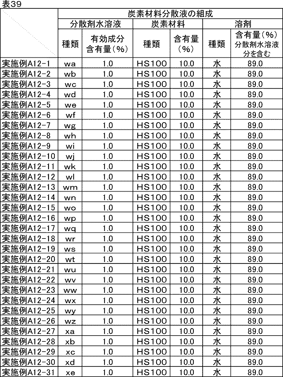

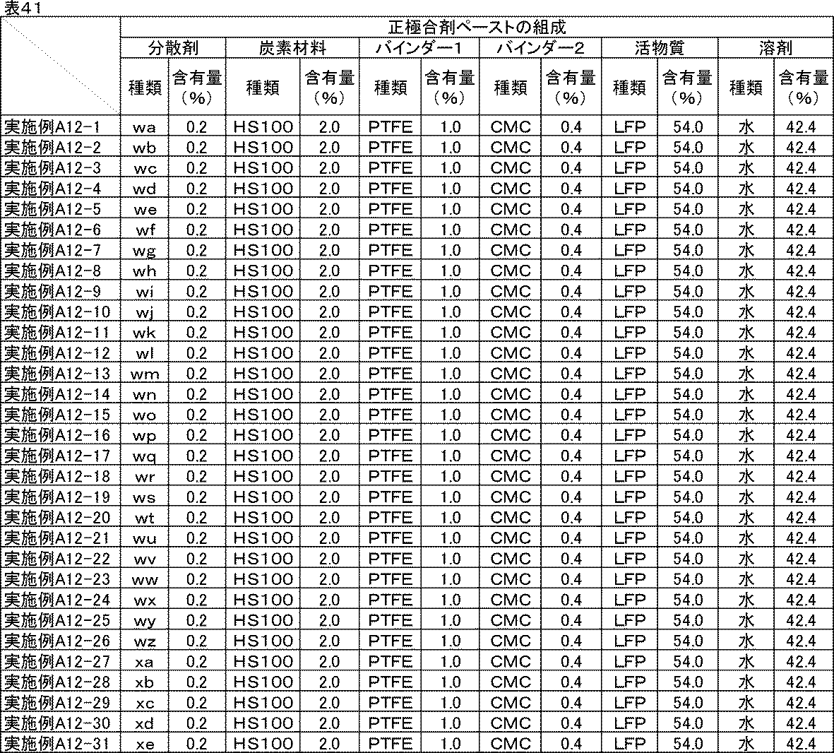
[比較例A12-1~12-4]
表42に示した炭素材料分散液、表43に示した炭素材料分散ワニス、表44に示した正極合剤ペーストの材料と組成に従い、実施例A12-2と同様な方法で分散し、正極評価用セルを組み立てた。比較例A12-4には分散剤を使用しなかった。
表42に示した炭素材料分散液、表43に示した炭素材料分散ワニス、表44に示した正極合剤ペーストの材料と組成に従い、実施例A12-2と同様な方法で分散し、正極評価用セルを組み立てた。比較例A12-4には分散剤を使用しなかった。
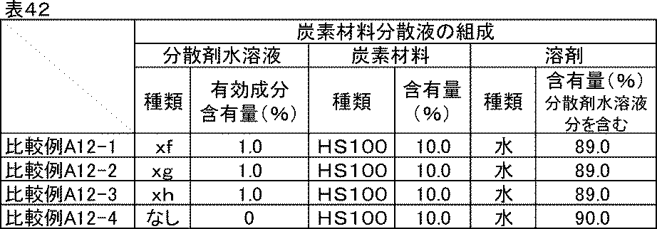


<評価結果>
実施例A12-1~A12-31で調製した炭素材料分散液、炭素材料分散ワニス、正極合剤ペーストはいずれも良好な分散状態であり、1か月経時後も沈降や増粘はなかった。比較例A12-1~A12-4は初期から高粘度で粗大粒子が多かったが、そのまま比較用に用いた。1か月経時後はゲル状になっていた。
実施例A12-1~A12-31で調製した炭素材料分散液、炭素材料分散ワニス、正極合剤ペーストはいずれも良好な分散状態であり、1か月経時後も沈降や増粘はなかった。比較例A12-1~A12-4は初期から高粘度で粗大粒子が多かったが、そのまま比較用に用いた。1か月経時後はゲル状になっていた。
トリアジン誘導体A~Tはトリアジン環直結の水酸基2つと酸性官能基を有するため、親水性が十分高く、優れた分散性を発揮したと考えられる。一方、トリアジン誘導体U~Wはこれらと比較して親水性が不十分であるため、水に対しては分散性が劣った。
実施例A12-1~A12-31、比較例A12-1~A12-4の正極評価用セルを用いて、実施例A2-1と同様な方法でイオン抵抗、反応抵抗、室温レート特性、低温放電特性の評価を行った。結果を表45に示す。

実施例A12-1~A12-31は、いずれの特性も優れており、アミンを無機塩基、溶剤を水とした場合でも同じ効果が得られることが確認できた。
[第2実施例群]
第2実施例群では、一般式(1)で表されるトリアジン誘導体のうち、R1が少なくとも-NHC(=O)-を含む置換基を有するフェニル基、ベンゾイミダゾール基、置換基を有してもよいインドール基または置換基を有してもよいピラゾール基であるものについて取り扱う。
第2実施例群では、一般式(1)で表されるトリアジン誘導体のうち、R1が少なくとも-NHC(=O)-を含む置換基を有するフェニル基、ベンゾイミダゾール基、置換基を有してもよいインドール基または置換基を有してもよいピラゾール基であるものについて取り扱う。
<分散剤>
以下に本発明の一般式(1)で表わされるトリアジン誘導体A~Yの構造を示す。本発明に用いる一般式(1)で表わされるトリアジン誘導体A~Yの製造方法としては、特に限定されるものではなく、周知の方法を適用することができる。例えば、特開2004-217842号公報等に記載されている方法を適用することができる。上記公報による開示を参照することにより、本明細書の一部に組み込むものとする。
以下に本発明の一般式(1)で表わされるトリアジン誘導体A~Yの構造を示す。本発明に用いる一般式(1)で表わされるトリアジン誘導体A~Yの製造方法としては、特に限定されるものではなく、周知の方法を適用することができる。例えば、特開2004-217842号公報等に記載されている方法を適用することができる。上記公報による開示を参照することにより、本明細書の一部に組み込むものとする。
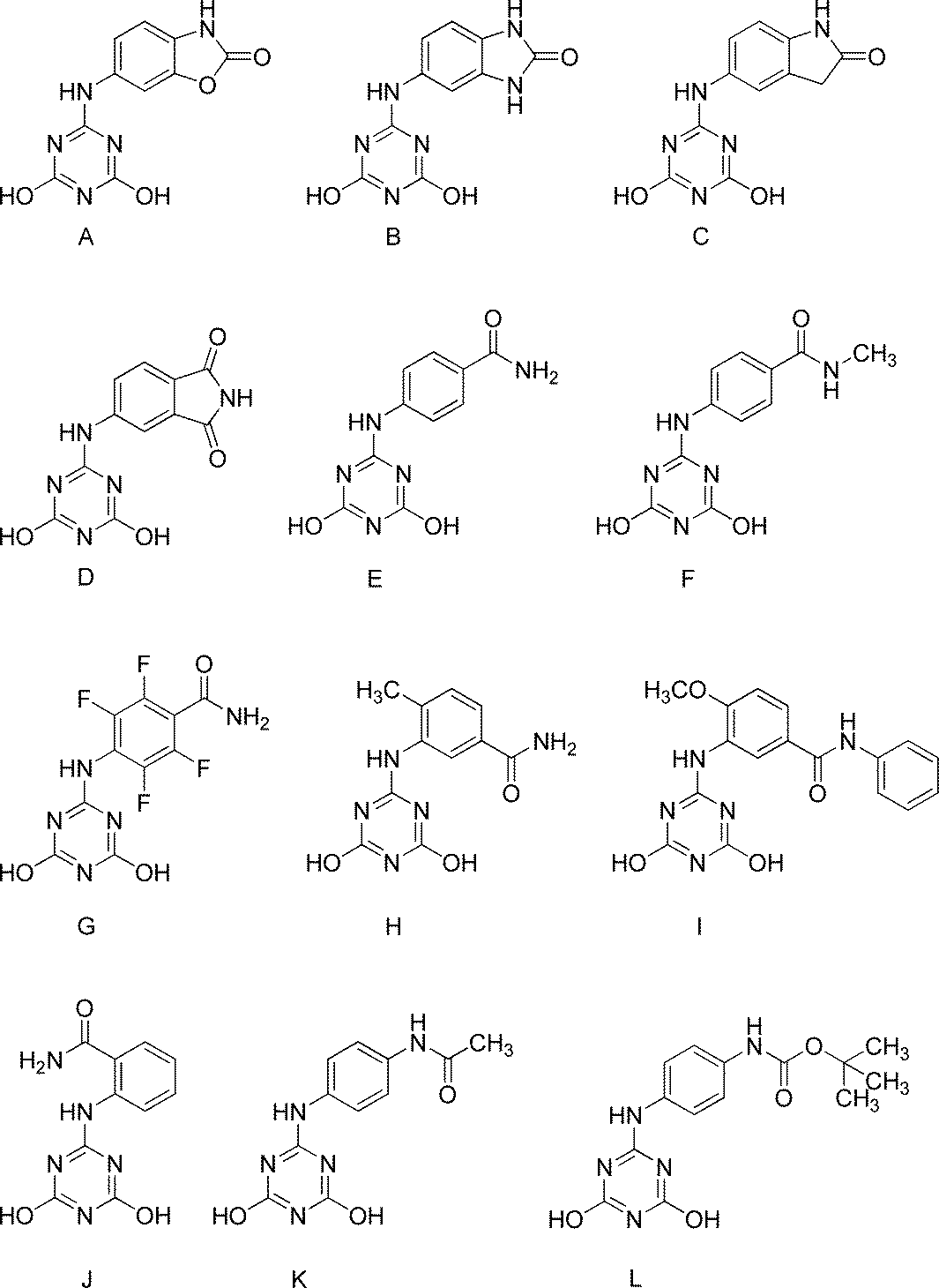
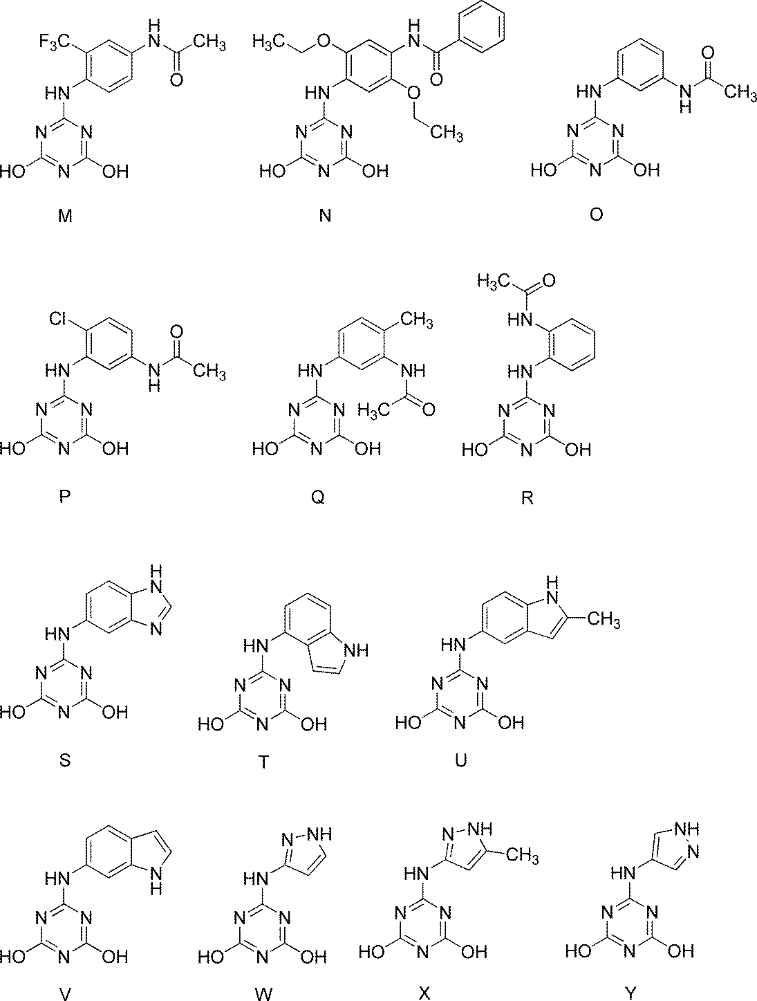
<トリアジン誘導体とアミンからなる分散剤の製造方法>
以下の実施例に記載した方法で表46記載の分散剤a~aoを製造した。
以下の実施例に記載した方法で表46記載の分散剤a~aoを製造した。
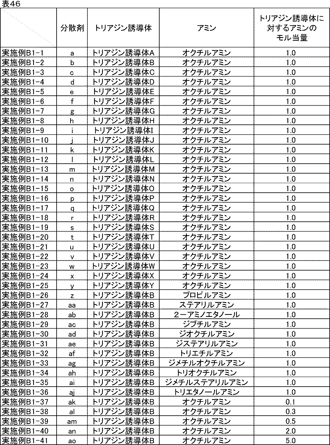
[実施例B1-1]
(分散剤aの製造)
水200gにトリアジン誘導体Aを0.040モル加えた。これにオクチルアミンを0.040モル加え、60℃で2時間撹拌した。室温まで冷却後、ろ過精製を行った。得られた残渣を90℃で48時間乾燥することにより、分散剤aを得た。
(分散剤aの製造)
水200gにトリアジン誘導体Aを0.040モル加えた。これにオクチルアミンを0.040モル加え、60℃で2時間撹拌した。室温まで冷却後、ろ過精製を行った。得られた残渣を90℃で48時間乾燥することにより、分散剤aを得た。
[実施例B1-2~B1-25]
(分散剤b~yの製造)
分散剤aの製造においてトリアジン誘導体Aの代わりに表46の実施例B1-2~B1-25に記載のトリアジン誘導体B~Yを添加した以外は、実施例B1-1と同様な方法で製造し、分散剤b~yを得た。
(分散剤b~yの製造)
分散剤aの製造においてトリアジン誘導体Aの代わりに表46の実施例B1-2~B1-25に記載のトリアジン誘導体B~Yを添加した以外は、実施例B1-1と同様な方法で製造し、分散剤b~yを得た。
[実施例B1-26~B1-36]
(分散剤z~ajの製造)
分散剤bの製造においてオクチルアミンの代わりに表46の実施例B1-26~B1-36に記載のアミンを添加した以外は、実施例B1-2と同様な方法で製造し、分散剤z~ajを得た。
(分散剤z~ajの製造)
分散剤bの製造においてオクチルアミンの代わりに表46の実施例B1-26~B1-36に記載のアミンを添加した以外は、実施例B1-2と同様な方法で製造し、分散剤z~ajを得た。
[実施例B1-37~B1-41]
(分散剤ak~aoの製造)
分散剤bの製造においてオクチルアミンの添加量を表46の実施例B1-37~B1-41に記載の添加量に変更した以外は実施例B1-2と同様な方法で製造し、分散剤ak~aoを得た。
(分散剤ak~aoの製造)
分散剤bの製造においてオクチルアミンの添加量を表46の実施例B1-37~B1-41に記載の添加量に変更した以外は実施例B1-2と同様な方法で製造し、分散剤ak~aoを得た。
以下に比較例で使用するトリアジン誘導体AA~ACの構造を示す。比較例に用いるトリアジン誘導体AA~ACの製造方法としては、特に限定されるものではなく、周知の方法を適用することができる。例えば、特開2004-217842号公報等に記載されている方法を適用することができる。上記公報による開示を参照することにより、本明細書の一部に組み込むものとする。

以下の比較例に記載した方法で表47記載の分散剤ba~bcを製造した。
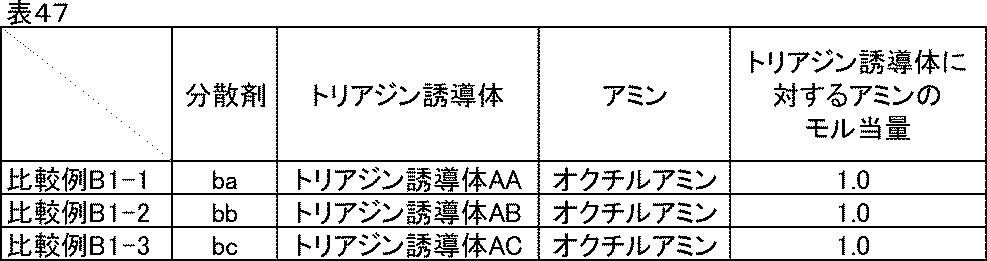
[比較例B1-1~1-3]
(分散剤ba~bcの製造)
分散剤aの製造においてトリアジン誘導体Aの代わりに表47の比較例B1-1~B1-3に載のトリアジン誘導体AA~ACを添加した以外は、実施例B1-1と同様な方法で製造し、分散剤ba~bcを得た。
(分散剤ba~bcの製造)
分散剤aの製造においてトリアジン誘導体Aの代わりに表47の比較例B1-1~B1-3に載のトリアジン誘導体AA~ACを添加した以外は、実施例B1-1と同様な方法で製造し、分散剤ba~bcを得た。
<トリアジン誘導体と無機塩基からなる分散剤の製造方法>
以下の実施例に記載した方法で表48記載の分散剤ca~diを製造した。
以下の実施例に記載した方法で表48記載の分散剤ca~diを製造した。
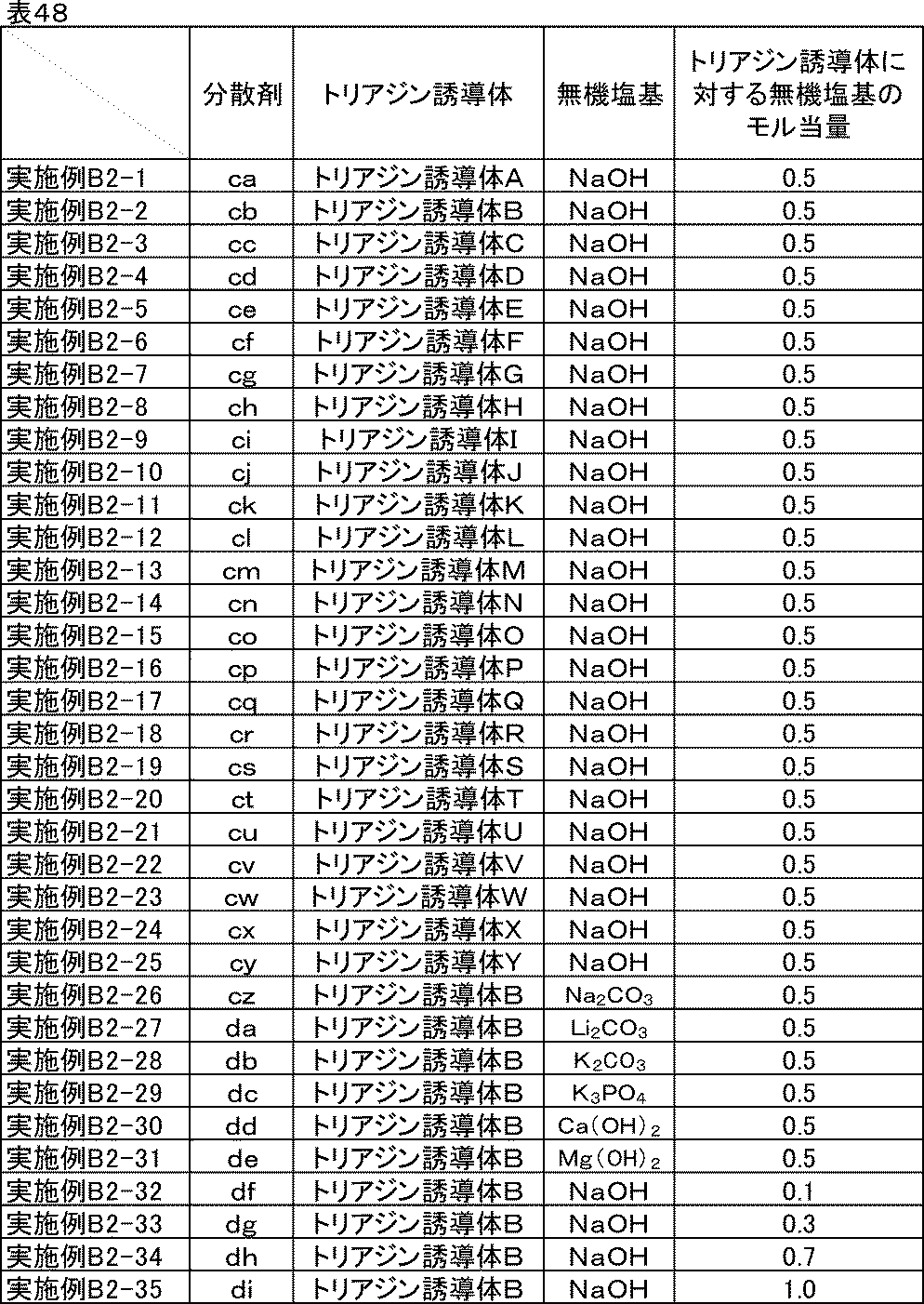
[実施例B2-1]
(分散剤caの製造)
水200gにトリアジン誘導体Aを0.040モル加えた。これに水酸化ナトリウムを0.020モル加え、60℃で2時間撹拌した。室温まで冷却後、ろ過精製を行った。得られた残渣を90℃で48時間乾燥することにより、分散剤caを得た。
(分散剤caの製造)
水200gにトリアジン誘導体Aを0.040モル加えた。これに水酸化ナトリウムを0.020モル加え、60℃で2時間撹拌した。室温まで冷却後、ろ過精製を行った。得られた残渣を90℃で48時間乾燥することにより、分散剤caを得た。
[実施例B2-2~B2-25]
(分散剤cb~cyの製造)
分散剤caの製造においてトリアジン誘導体Aの代わりに表48の実施例B2-2~B2-25に記載のトリアジン誘導体B~Yを添加した以外は、実施例B2-1と同様な方法で製造し、分散剤cb~cyを得た。
(分散剤cb~cyの製造)
分散剤caの製造においてトリアジン誘導体Aの代わりに表48の実施例B2-2~B2-25に記載のトリアジン誘導体B~Yを添加した以外は、実施例B2-1と同様な方法で製造し、分散剤cb~cyを得た。
[実施例B2-26~B2-31]
(分散剤cz~deの製造)
分散剤cbの製造において水酸化ナトリウムの代わりに表48の実施例B2-26~B2-31に記載の無機塩基を添加した以外は、実施例B2-2と同様な方法で製造し、分散剤cz~deを得た。
(分散剤cz~deの製造)
分散剤cbの製造において水酸化ナトリウムの代わりに表48の実施例B2-26~B2-31に記載の無機塩基を添加した以外は、実施例B2-2と同様な方法で製造し、分散剤cz~deを得た。
[実施例B2-32~B2-35]
(分散剤df~diの製造)
分散剤cbの製造において水酸化ナトリウムの添加量を表48の実施例B2-32~B2-35に記載の添加量に変更した以外は実施例B2-2と同様な方法で製造し、分散剤df~diを得た。
(分散剤df~diの製造)
分散剤cbの製造において水酸化ナトリウムの添加量を表48の実施例B2-32~B2-35に記載の添加量に変更した以外は実施例B2-2と同様な方法で製造し、分散剤df~diを得た。
以下の比較例に記載した方法で表49記載の分散剤ea~ecを製造した。

[比較例B2-1~2-3]
(分散剤ea~ecの製造)
分散剤caの製造においてトリアジン誘導体Aの代わりに表49の比較例B2-1~B2-3に記載のトリアジン誘導体AA~ACを添加した以外は、実施例B2-1と同様な方法で製造し、分散剤ea~ecを得た。
(分散剤ea~ecの製造)
分散剤caの製造においてトリアジン誘導体Aの代わりに表49の比較例B2-1~B2-3に記載のトリアジン誘導体AA~ACを添加した以外は、実施例B2-1と同様な方法で製造し、分散剤ea~ecを得た。
実施例、比較例に示す炭素材料分散液、炭素材料分散ワニス、合剤ペーストは、以下に示す材料を用いて作製した。
[実施例B3-1]
<炭素材料分散液の調製>
表50に示す組成に従い、ガラス瓶にN-メチル-2-ピロリドンと分散剤aを仕込み、混合した後、炭素材料を加え、ジルコニアビーズをメディアとして、ペイントコンディショナーで2時間分散し、分散剤aを含む炭素材料分散液を得た。
<炭素材料分散液の調製>
表50に示す組成に従い、ガラス瓶にN-メチル-2-ピロリドンと分散剤aを仕込み、混合した後、炭素材料を加え、ジルコニアビーズをメディアとして、ペイントコンディショナーで2時間分散し、分散剤aを含む炭素材料分散液を得た。
<炭素材料分散ワニスの調製>
表50に示す組成に従い、調製した分散剤aを含む炭素材料分散液とバインダー、N-メチル-2-ピロリドンをディスパーにて混合し、炭素材料分散ワニスを得た。
表50に示す組成に従い、調製した分散剤aを含む炭素材料分散液とバインダー、N-メチル-2-ピロリドンをディスパーにて混合し、炭素材料分散ワニスを得た。
<正極合剤ペーストの調製>
表50に示す組成に従い、調製した分散剤aを含む炭素材料分散ワニスと活物質、N-メチル-2-ピロリドンをディスパーにて混合し、正極合剤ペーストを得た。
表50に示す組成に従い、調製した分散剤aを含む炭素材料分散ワニスと活物質、N-メチル-2-ピロリドンをディスパーにて混合し、正極合剤ペーストを得た。
<電極の作製>
調製した分散剤aを含む正極合剤ペーストを、厚さ20μmのアルミ箔上にドクターブレードを用いて塗工した後、減圧下120℃で30分間乾燥し、ローラープレス機にて圧延処理し、塗布量17mg/cm2、密度3.0g/cm3の電極を作製した。厚みや密度が均一な電極が得られた。
調製した分散剤aを含む正極合剤ペーストを、厚さ20μmのアルミ箔上にドクターブレードを用いて塗工した後、減圧下120℃で30分間乾燥し、ローラープレス機にて圧延処理し、塗布量17mg/cm2、密度3.0g/cm3の電極を作製した。厚みや密度が均一な電極が得られた。
<リチウムイオン二次電池正極評価用セルの組み立て>
作製した分散剤aを含む電極を直径16mmに打ち抜き正極とし、金属リチウム箔(厚さ0.15mm)を負極として、正極および負極の間に多孔質ポリプロピレンフィルムからなるセパレーター(厚さ20μm、空孔率50%)を挿入積層し、電解液(エチレンカーボネートとジエチルカーボネートを体積比1:1に混合した混合溶媒にLiPF6を1Mの濃度で溶解させた非水電解液)を0.1ml満たして二極密閉式金属セル(宝泉社製HSフラットセル)を組み立てた。セルの組み立てはアルゴンガス置換したグローブボックス内で行った。
作製した分散剤aを含む電極を直径16mmに打ち抜き正極とし、金属リチウム箔(厚さ0.15mm)を負極として、正極および負極の間に多孔質ポリプロピレンフィルムからなるセパレーター(厚さ20μm、空孔率50%)を挿入積層し、電解液(エチレンカーボネートとジエチルカーボネートを体積比1:1に混合した混合溶媒にLiPF6を1Mの濃度で溶解させた非水電解液)を0.1ml満たして二極密閉式金属セル(宝泉社製HSフラットセル)を組み立てた。セルの組み立てはアルゴンガス置換したグローブボックス内で行った。

[実施例B3-2~B3-76]分散剤種の比較-1
分散剤aを用いた代わりに、表51に示した分散剤b~ao、ca~diをそれぞれ用いた以外は実施例B3-1と同様な組成および方法で分散し、正極評価用セルを組み立てた。
分散剤aを用いた代わりに、表51に示した分散剤b~ao、ca~diをそれぞれ用いた以外は実施例B3-1と同様な組成および方法で分散し、正極評価用セルを組み立てた。
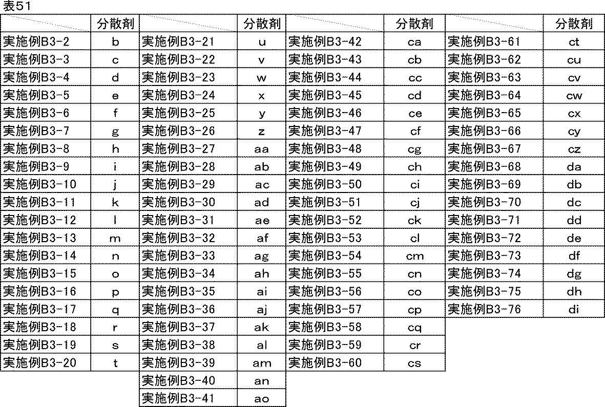
[比較例B3-1~B3-7]分散剤種の比較-2
表52に示した分散剤ba~bc、ea~ecを用いた以外は実施例B3-1と同様な方法で分散し、正極評価用セルを組み立てた。ただし、比較例B3-7には分散剤を用いず、その分の組成は溶剤に振り替えた。
表52に示した分散剤ba~bc、ea~ecを用いた以外は実施例B3-1と同様な方法で分散し、正極評価用セルを組み立てた。ただし、比較例B3-7には分散剤を用いず、その分の組成は溶剤に振り替えた。
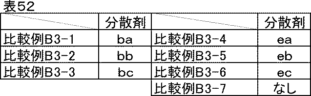
<イオン抵抗評価>
実施例B3-1~B3-76、比較例B3-1~B3-7で組み立てた正極評価用セルを-20℃の恒温槽内で12時間静置し、開回路電位にて周波数0.1Hz、振幅10mVで交流インピーダンス測定を行い、イオン抵抗|Z|ionを求めた。続いて正極評価用セルを室温(25℃)に移して3時間静置し、同様にインピーダンス測定を行い、イオン抵抗|Z|ionを求めた。測定にはインピーダンスアナライザーを用いた。
実施例B3-1~B3-76、比較例B3-1~B3-7で組み立てた正極評価用セルを-20℃の恒温槽内で12時間静置し、開回路電位にて周波数0.1Hz、振幅10mVで交流インピーダンス測定を行い、イオン抵抗|Z|ionを求めた。続いて正極評価用セルを室温(25℃)に移して3時間静置し、同様にインピーダンス測定を行い、イオン抵抗|Z|ionを求めた。測定にはインピーダンスアナライザーを用いた。
<反応抵抗評価>
イオン抵抗評価に続いて、充放電測定装置を用い、室温にて0.1Cの定電流定電圧充電(上限電圧4.2V)で満充電とし、0.1Cの定電流で放電下限電圧3.0Vまで放電を行う充放電を1サイクルとして合計5サイクル行った。5サイクル目の0.1C放電容量を記録しておいた。次に、3.0Vまで放電した状態の正極評価用セルをインピーダンスアナライザーに接続し、3.0V、振幅10mV、周波数0.1Hzから1MHzにおいて交流インピーダンス測定を行った。結果をコールコールプロット法にて複素平面上にプロットすると、半円状の曲線が得られる。この円弧の直径を活物質の反応抵抗|Z|reとした。
イオン抵抗評価に続いて、充放電測定装置を用い、室温にて0.1Cの定電流定電圧充電(上限電圧4.2V)で満充電とし、0.1Cの定電流で放電下限電圧3.0Vまで放電を行う充放電を1サイクルとして合計5サイクル行った。5サイクル目の0.1C放電容量を記録しておいた。次に、3.0Vまで放電した状態の正極評価用セルをインピーダンスアナライザーに接続し、3.0V、振幅10mV、周波数0.1Hzから1MHzにおいて交流インピーダンス測定を行った。結果をコールコールプロット法にて複素平面上にプロットすると、半円状の曲線が得られる。この円弧の直径を活物質の反応抵抗|Z|reとした。
<室温レート特性・低温放電特性評価>
次に、室温にて0.1Cで同様に満充電にした後、0.5Cの定電流で放電下限電圧3.0Vまで放電し、再度0.1Cで満充電にしてから5Cの定電流で3.0Vまで放電した。反応抵抗評価の試験で記録しておいた5サイクル目の0.1C放電容量に対する5C放電容量の比率を、室温レート特性(%)とした。またここで、室温における0.5C放電容量を記録しておいた。続いて、室温、0.1Cで同様に満充電にしてから-20℃の恒温槽内に移して12時間静置した後に、0.5Cの定電流で同じく放電した。室温の0.5C放電容量に対する-20℃の0.5C放電容量の比率を、低温放電特性(%)とした。室温レート特性、低温放電特性共に100%に近いほど良好である。
次に、室温にて0.1Cで同様に満充電にした後、0.5Cの定電流で放電下限電圧3.0Vまで放電し、再度0.1Cで満充電にしてから5Cの定電流で3.0Vまで放電した。反応抵抗評価の試験で記録しておいた5サイクル目の0.1C放電容量に対する5C放電容量の比率を、室温レート特性(%)とした。またここで、室温における0.5C放電容量を記録しておいた。続いて、室温、0.1Cで同様に満充電にしてから-20℃の恒温槽内に移して12時間静置した後に、0.5Cの定電流で同じく放電した。室温の0.5C放電容量に対する-20℃の0.5C放電容量の比率を、低温放電特性(%)とした。室温レート特性、低温放電特性共に100%に近いほど良好である。
<評価結果>
実施例B3-1~B3-76、比較例B3-1~B3-6に記載の炭素材料分散液、炭素材料分散ワニス、正極合剤ペーストは良好な分散状態であり、1か月経時後も沈降や増粘はなかった。分散剤を用いていない比較例B3-7は初期からかなりの高粘度で流動性が悪かったが、そのまま比較用に用いた。また、1か月経時後はゲル状になっていた。
実施例B3-1~B3-76、比較例B3-1~B3-6に記載の炭素材料分散液、炭素材料分散ワニス、正極合剤ペーストは良好な分散状態であり、1か月経時後も沈降や増粘はなかった。分散剤を用いていない比較例B3-7は初期からかなりの高粘度で流動性が悪かったが、そのまま比較用に用いた。また、1か月経時後はゲル状になっていた。
実施例B3-1~B3-76、比較例B3-1~B3-7の正極評価用セルのイオン抵抗、反応抵抗、室温レート特性、低温放電特性の評価結果を表53-1、表53-2に示す。
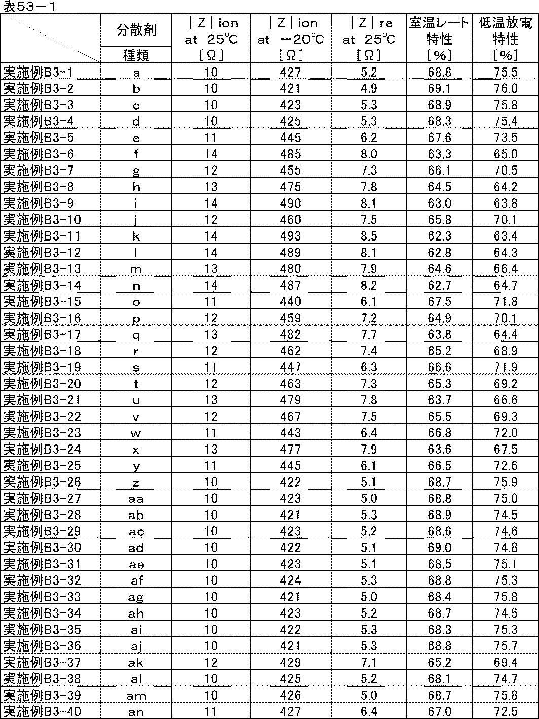
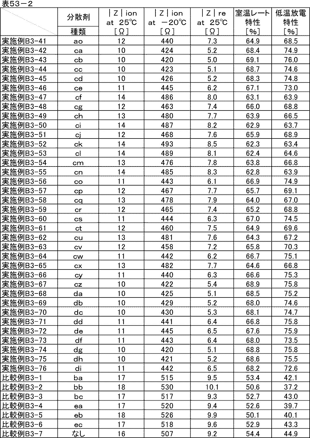
表53-1、53-2からわかる通り、分散剤a~ao、ca~diを用いた実施例B3-1~B3-76の正極は室温および-20℃のイオン抵抗、反応抵抗、室温レート特性、低温放電特性の全てにおいて、分散剤を用いない比較例B3-7や分散剤ba~bc、ea~ecを用いた比較例3-1~3-6の正極と比べて非常に優れていた。
分散剤a~ao、ca~diは、極めて電子密度の高いLi+が近傍に存在することで、誘電分極を生じ、電池内では高い誘電率で存在していると考えられる。これによりイオン伝導度を向上させたり、活物質とLiが反応する際のLi+の脱溶媒和エネルギーや溶媒和エネルギーを低減させ、結果としてイオン抵抗および反応抵抗が小さくなって、電池全体としても特性が向上すると思われる。
[実施例B4-1~B4-5][比較例B4-1~B4-5]炭素材料種の比較
表54に示した炭素材料分散液、表55に示した炭素材料分散ワニス、表56に示した正極合剤ペーストの材料と組成に従い、実施例B3-1と同様な方法で分散し、正極評価用セルを組み立てた。高比表面積の炭素材料に対しては分散剤が多く必要であるため、それぞれの炭素材料に合わせて適宜使用量を決定した。
表54に示した炭素材料分散液、表55に示した炭素材料分散ワニス、表56に示した正極合剤ペーストの材料と組成に従い、実施例B3-1と同様な方法で分散し、正極評価用セルを組み立てた。高比表面積の炭素材料に対しては分散剤が多く必要であるため、それぞれの炭素材料に合わせて適宜使用量を決定した。
(炭素材料分散液の組成)

(炭素材料分散ワニスの組成)
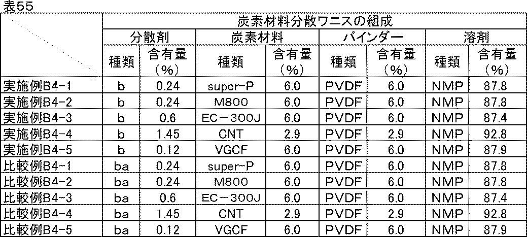
(正極合剤ペーストの組成)

<評価結果>
いずれの実施例、比較例に記載の炭素材料分散液、炭素材料分散ワニス、正極合剤ペーストも良好な分散状態であり、1か月経時後も沈降や増粘はなかった。
いずれの実施例、比較例に記載の炭素材料分散液、炭素材料分散ワニス、正極合剤ペーストも良好な分散状態であり、1か月経時後も沈降や増粘はなかった。
実施例B4-1~B4-5、比較例B4-1~B4-5の正極評価用セルのイオン抵抗、反応抵抗、室温レート特性、低温放電特性の評価結果を表57に示す。

いずれの炭素材料であっても同様の効果が確認できた。実施例B4-1~B4-5の差異は炭素材料の導電性による差異であると考えられる。また、比較例B4-1~B4-5では、分散剤の添加量が多いものほど抵抗が高く特性が悪い傾向にあった。
以上の検証から、先に述べた効果は炭素材料種によらないことが確認できた。
[実施例B5-1~B5-6]活物質表面積あたりの分散剤量の比較-1
実施例B3-2の分散剤量の代わりに、表58、表59、表60に示す分散剤量とした以外は同様にして正極評価用セルを組み立てた。電極中の活物質表面積1m2に対する分散剤量(mg)を表61に示した。
実施例B3-2の分散剤量の代わりに、表58、表59、表60に示す分散剤量とした以外は同様にして正極評価用セルを組み立てた。電極中の活物質表面積1m2に対する分散剤量(mg)を表61に示した。
(炭素材料分散液の組成)
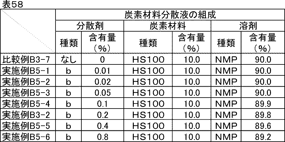
(炭素材料分散ワニスの組成)
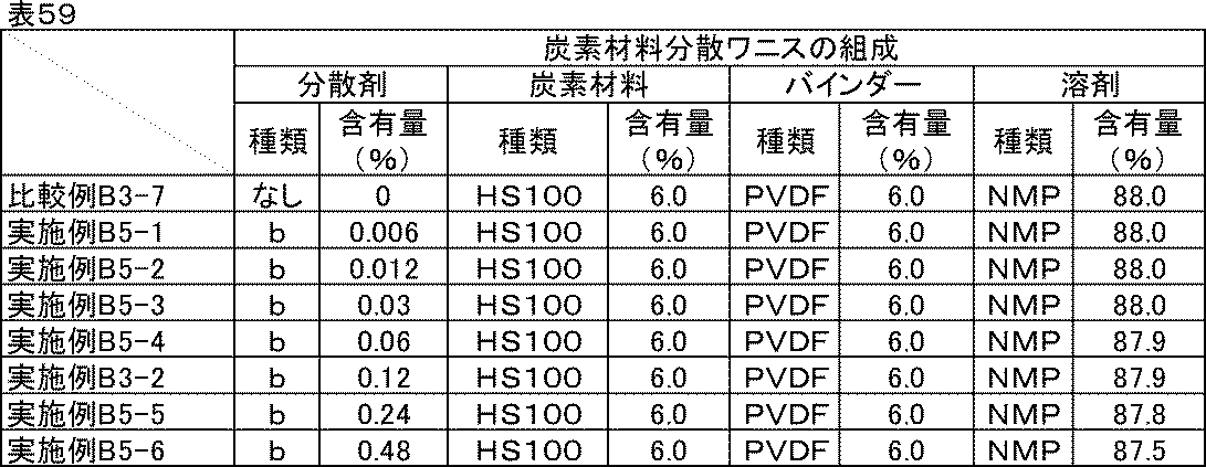
(正極合剤ペーストの組成)
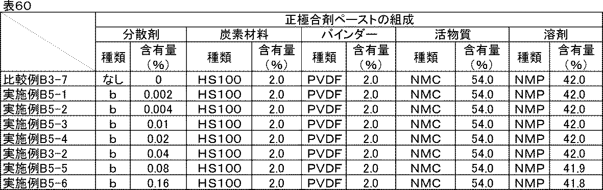
(活物質表面積あたりの分散剤量)
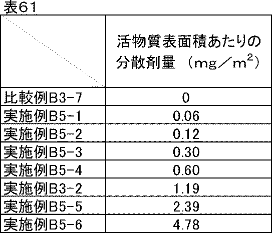
<評価結果>
比較例B3-7、実施例B3-2、実施例B5-1~B5-6の反応抵抗、室温レート特性、低温放電特性の評価結果を表62に示す。
比較例B3-7、実施例B3-2、実施例B5-1~B5-6の反応抵抗、室温レート特性、低温放電特性の評価結果を表62に示す。
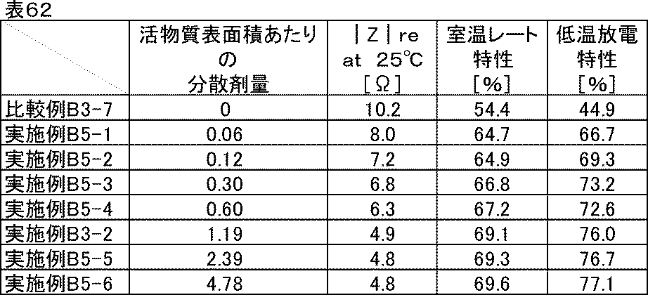
実施例B5-1から、活物質表面積に対する分散剤量が少なすぎると効果が小さくなることがわかった。実施例B5-2の分散剤量以上で特に大きな効果が得られるようになり、分散剤量が増えるにつれて徐々に良化した。
[実施例B6-1~B6-9]活物質表面積あたりの分散剤量の比較-2
表63、表64、表65に示す材料、組成にて実施例B3-2と同様に分散し、正極評価用セルを作製した。電極中の活物質表面積1m2に対する分散剤量(mg)を表66に示した。
表63、表64、表65に示す材料、組成にて実施例B3-2と同様に分散し、正極評価用セルを作製した。電極中の活物質表面積1m2に対する分散剤量(mg)を表66に示した。
(炭素材料分散液の組成)

(炭素材料分散ワニスの組成)
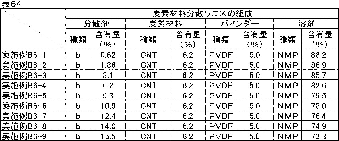
(正極合剤ペーストの組成)

(活物質表面積あたりの分散剤量)
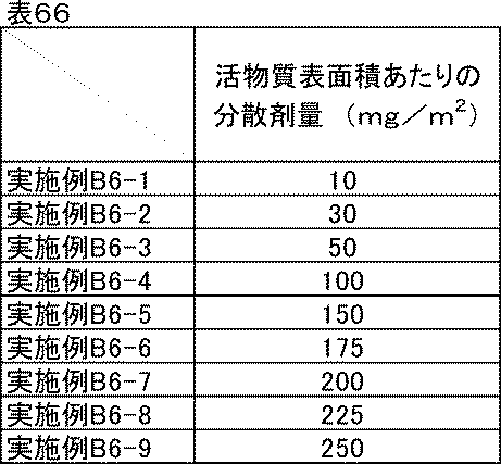
<評価結果>
実施例B6-1~実施例B6-9、の反応抵抗、室温レート特性、低温放電特性の評価結果を表67に示す。
実施例B6-1~実施例B6-9、の反応抵抗、室温レート特性、低温放電特性の評価結果を表67に示す。

表67より、実施例B6-6の分散剤量を超えると反応抵抗低減効果が小さくなることがわかった。分散剤量が過剰になると、脱溶媒和エネルギーの低減以上に抵抗成分としての悪影響が大きくなることによると考えられる。
以上のことから、より大きな反応抵抗低減効果を得るためには、活物質表面積に対する分散剤添加量の最適な範囲が存在することがわかった。
[実施例B7-1~B7-6]電解液量に対する分散剤量の比較-1
実施例B5-2で作製した正極を用いて、表68に示す電解液の量に変更した以外は、実施例B5-2と同様に正極評価用セルを組み立てた。
実施例B5-2で作製した正極を用いて、表68に示す電解液の量に変更した以外は、実施例B5-2と同様に正極評価用セルを組み立てた。
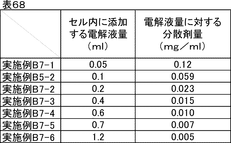
[実施例B8-1~B8-7]電解液量に対する分散剤量の比較-2
実施例B6-3で作製した正極合剤ペーストを用いて、塗布量を28mg/cm2に変更した以外は実施例B6-3と同様な方法で正極を作製した。さらに、正極評価用セルに添加する電解液の量を表69に示す量に変更し、それ以外は実施例B6-3と同様に正極評価用セルを組み立てた。
実施例B6-3で作製した正極合剤ペーストを用いて、塗布量を28mg/cm2に変更した以外は実施例B6-3と同様な方法で正極を作製した。さらに、正極評価用セルに添加する電解液の量を表69に示す量に変更し、それ以外は実施例B6-3と同様に正極評価用セルを組み立てた。
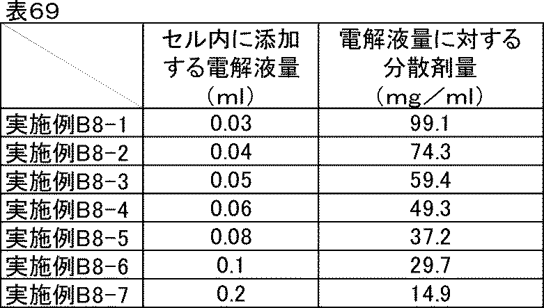
<評価結果>
実施例B5-2、実施例B7-1~B7-6、比較例B3-7のイオン抵抗、反応抵抗、室温レート特性、低温放電特性の評価結果を表70に示す。実施例B8-1~B8-7のイオン抵抗、反応抵抗、室温レート特性、低温放電特性の評価結果を表71に示す。
実施例B5-2、実施例B7-1~B7-6、比較例B3-7のイオン抵抗、反応抵抗、室温レート特性、低温放電特性の評価結果を表70に示す。実施例B8-1~B8-7のイオン抵抗、反応抵抗、室温レート特性、低温放電特性の評価結果を表71に示す。
実施例B5-2、実施例B7-1~B7-6の反応抵抗はいずれも同等であった。これは、活物質表面積に対する分散剤量が等しいことによると考えられる。
また、実施例B7-1~B7-4では室温および低温のイオン抵抗は比較例B3-7に比べて大幅に低くなっており、実施例B7-4を下限に実施例B7-5、B7-6では効果が小さくなった。大きな効果を得るには、電解液量に対する分散剤最適量の下限が存在することが示された。
室温レート特性および低温放電特性はイオン抵抗と反応抵抗両方の影響を受けるため、電池として優れた特性を得るためには両方の効果が得られるよう設計するのが良い。
一方、実施例B8-1~B8-7の比較から、電解液量に対する分散剤量が多すぎてもイオン抵抗低減効果が小さくなることがわかった。これは、分散剤は絶縁性の化合物であるため、過剰にあると、それ自体が抵抗成分になってしまうことによると考えられる。
以上のことから、電解液量に対する分散剤最適量には上限も存在することがわかった。

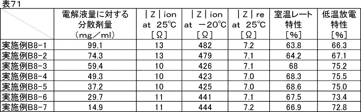
[実施例B9-1]電解液の影響調査
実施例B3-2で用いた電解液(エチレンカーボネートとジエチルカーボネートを体積比1:1に混合した混合溶媒にLiPF6を1Mの濃度で溶解させた非水電解液)の代わりに、エチレンカーボネートとジエチルカーボネートを体積比1:2に混合した混合溶媒に、LiPF6を1Mの濃度で溶解させた非水電解液を用いた以外は、実施例B3-2と同様に正極評価用セルを組み立てた。
実施例B3-2で用いた電解液(エチレンカーボネートとジエチルカーボネートを体積比1:1に混合した混合溶媒にLiPF6を1Mの濃度で溶解させた非水電解液)の代わりに、エチレンカーボネートとジエチルカーボネートを体積比1:2に混合した混合溶媒に、LiPF6を1Mの濃度で溶解させた非水電解液を用いた以外は、実施例B3-2と同様に正極評価用セルを組み立てた。
[実施例B9-2]
実施例B3-2で用いた電解液(エチレンカーボネートとジエチルカーボネートを体積比1:1に混合した混合溶媒にLiPF6を1Mの濃度で溶解させた非水電解液)の代わりに、エチレンカーボネートとエチルメチルカーボネート、ジメチルカーボネートを体積比1:1:1に混合した混合溶媒に、LiPF6を1Mの濃度で溶解させた非水電解液を用いた以外は、実施例B3-2と同様に正極評価用セルを組み立てた。
実施例B3-2で用いた電解液(エチレンカーボネートとジエチルカーボネートを体積比1:1に混合した混合溶媒にLiPF6を1Mの濃度で溶解させた非水電解液)の代わりに、エチレンカーボネートとエチルメチルカーボネート、ジメチルカーボネートを体積比1:1:1に混合した混合溶媒に、LiPF6を1Mの濃度で溶解させた非水電解液を用いた以外は、実施例B3-2と同様に正極評価用セルを組み立てた。
[比較例B9-1]
比較例B3-7で用いた電解液(エチレンカーボネートとジエチルカーボネートを体積比1:1に混合した混合溶媒にLiPF6を1Mの濃度で溶解させた非水電解液)の代わりに、エチレンカーボネートとジエチルカーボネートを体積比1:2に混合した混合溶媒にLiPF6を1Mの濃度で溶解させた非水電解液を用いた以外は、比較例B3-7と同様に正極評価用セルを組み立てた。
比較例B3-7で用いた電解液(エチレンカーボネートとジエチルカーボネートを体積比1:1に混合した混合溶媒にLiPF6を1Mの濃度で溶解させた非水電解液)の代わりに、エチレンカーボネートとジエチルカーボネートを体積比1:2に混合した混合溶媒にLiPF6を1Mの濃度で溶解させた非水電解液を用いた以外は、比較例B3-7と同様に正極評価用セルを組み立てた。
[比較例B9-2]
比較例B3-7で用いた電解液(エチレンカーボネートとジエチルカーボネートを体積比1:1に混合した混合溶媒にLiPF6を1Mの濃度で溶解させた非水電解液)の代わりに、エチレンカーボネートとエチルメチルカーボネート、ジメチルカーボネートを体積比1:1:1に混合した混合溶媒に、LiPF6を1Mの濃度で溶解させた非水電解液を用いた以外は、比較例B3-7と同様に正極評価用セルを組み立てた。
比較例B3-7で用いた電解液(エチレンカーボネートとジエチルカーボネートを体積比1:1に混合した混合溶媒にLiPF6を1Mの濃度で溶解させた非水電解液)の代わりに、エチレンカーボネートとエチルメチルカーボネート、ジメチルカーボネートを体積比1:1:1に混合した混合溶媒に、LiPF6を1Mの濃度で溶解させた非水電解液を用いた以外は、比較例B3-7と同様に正極評価用セルを組み立てた。
<評価結果>
実施例B3-2、実施例B9-1、実施例B9-2、比較例B3-7、比較例B9-1、比較例B9-2のイオン抵抗、反応抵抗、室温レート特性、低温放電特性の評価結果を表72に示す。
実施例B3-2、実施例B9-1、実施例B9-2、比較例B3-7、比較例B9-1、比較例B9-2のイオン抵抗、反応抵抗、室温レート特性、低温放電特性の評価結果を表72に示す。
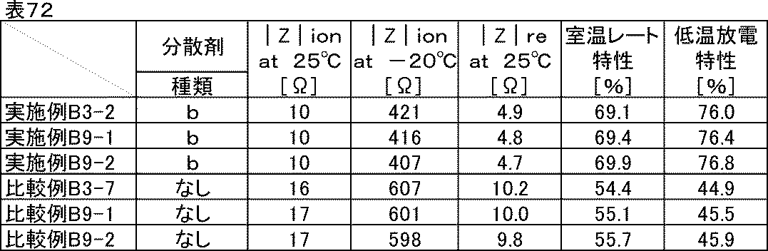
実施例B9-1、実施例B9-2より、電解液の種類によらず、すべての特性が比較例よりも良化することが確認できた。本実施例に示した電解液以外でも、一般的に用いられる非水電解液であれば、種類によらず同じ効果が得られると思われる。
次に、活物質の種類を変更して同様に評価した。
[実施例B10-1~B10-3]活物質種の比較
実施例B3-2で用いた炭素材料分散ワニスを用いて、表73に示した活物質と組成に従って、実施例B3-2と同様な方法で分散し、正極評価用セルを組み立てた。
実施例B3-2で用いた炭素材料分散ワニスを用いて、表73に示した活物質と組成に従って、実施例B3-2と同様な方法で分散し、正極評価用セルを組み立てた。
[比較例B10-1~B10-3]
比較例B3-1で用いた炭素材料分散ワニスを用いて、表73に示した活物質と組成に従って、比較例B3-1と同様な方法で分散し、正極評価用セルを組み立てた。
比較例B3-1で用いた炭素材料分散ワニスを用いて、表73に示した活物質と組成に従って、比較例B3-1と同様な方法で分散し、正極評価用セルを組み立てた。

<評価結果>
実施例B10-1~B10-3、比較例B10-1~B10-3のイオン抵抗、反応抵抗、室温レート特性、低温放電特性の評価結果を表74に示す。
実施例B10-1~B10-3、比較例B10-1~B10-3のイオン抵抗、反応抵抗、室温レート特性、低温放電特性の評価結果を表74に示す。

活物質の性能によって電池の特性に差異はあるものの、同じ活物質で実施例と比較例を比較すると、実施例B10-1~B10-3はいずれも特性が向上していることが確認できた。
続いて、本発明の分散組成物を負極に用いた場合の評価を行った。
[実施例B11-1]
<炭素材料分散ワニスの調製>
表75に示す組成に従い、実施例B3-1で作製した分散剤aを含む炭素材料分散液とバインダー、N-メチル-2-ピロリドンをディスパーにて混合し、炭素材料分散ワニスを得た。
<炭素材料分散ワニスの調製>
表75に示す組成に従い、実施例B3-1で作製した分散剤aを含む炭素材料分散液とバインダー、N-メチル-2-ピロリドンをディスパーにて混合し、炭素材料分散ワニスを得た。
<負極合剤ペーストの調製>
表75に示す組成に従い、調製した分散剤aを含む炭素材料分散ワニスと活物質、N-メチル-2-ピロリドンをディスパーにて混合し、負極合剤ペーストを得た。
表75に示す組成に従い、調製した分散剤aを含む炭素材料分散ワニスと活物質、N-メチル-2-ピロリドンをディスパーにて混合し、負極合剤ペーストを得た。

<電極の作製>
調製した分散剤aを含む負極合剤ペーストを、厚さ20μmの銅箔上にドクターブレードを用いて塗工した後、減圧下120℃で30分間乾燥し、ローラープレス機にて圧延処理し、塗布量15mg/cm2、密度1.8g/cm3の電極を作製した。厚みや密度が均一な電極が得られた。
調製した分散剤aを含む負極合剤ペーストを、厚さ20μmの銅箔上にドクターブレードを用いて塗工した後、減圧下120℃で30分間乾燥し、ローラープレス機にて圧延処理し、塗布量15mg/cm2、密度1.8g/cm3の電極を作製した。厚みや密度が均一な電極が得られた。
<リチウムイオン二次電池負極評価用セルの組み立て>
作製した分散剤aを含む電極を直径18mmに打ち抜き負極とし、金属リチウム箔(厚さ0.15mm)を正極として、負極および正極の間に多孔質ポリプロピレンフィルムからなるセパレーター(厚さ20μm、空孔率50%)を挿入積層し、電解液(エチレンカーボネートとジエチルカーボネートを体積比1:1に混合した混合溶媒にLiPF6を1Mの濃度で溶解させた非水電解液)を0.1ml満たして二極密閉式金属セル(宝泉社製HSフラットセル)を組み立てた。セルの組み立てはアルゴンガス置換したグローブボックス内で行った。
作製した分散剤aを含む電極を直径18mmに打ち抜き負極とし、金属リチウム箔(厚さ0.15mm)を正極として、負極および正極の間に多孔質ポリプロピレンフィルムからなるセパレーター(厚さ20μm、空孔率50%)を挿入積層し、電解液(エチレンカーボネートとジエチルカーボネートを体積比1:1に混合した混合溶媒にLiPF6を1Mの濃度で溶解させた非水電解液)を0.1ml満たして二極密閉式金属セル(宝泉社製HSフラットセル)を組み立てた。セルの組み立てはアルゴンガス置換したグローブボックス内で行った。
[実施例B11-2~B11-76]
実施例B3-2~B3-76で作製した分散剤b~ao、分散剤ca~diをそれぞれ含む炭素材料分散液を用いて、実施例B11-1と同じ組成、方法で分散し、炭素材料分散ワニス、負極合剤ペーストを作製して、負極評価用セルを組み立てた。用いた炭素材料分散液と分散剤の対応は表76に示した。
実施例B3-2~B3-76で作製した分散剤b~ao、分散剤ca~diをそれぞれ含む炭素材料分散液を用いて、実施例B11-1と同じ組成、方法で分散し、炭素材料分散ワニス、負極合剤ペーストを作製して、負極評価用セルを組み立てた。用いた炭素材料分散液と分散剤の対応は表76に示した。
[比較例B11-1~B11-7]
比較例B3-1~B3-7で作製した分散剤ba~bc、分散剤ea~ecをそれぞれ含む炭素材料分散液を用いて、実施例B11-1と同じ組成、方法で分散し、炭素材料分散ワニス、負極合剤ペーストを作製して、負極評価用セルを組み立てた。ただし、比較例B11-7には分散剤を用いず、その分の組成は溶剤に振り替えた。用いた炭素材料分散液と分散剤の対応は表77に示した。
比較例B3-1~B3-7で作製した分散剤ba~bc、分散剤ea~ecをそれぞれ含む炭素材料分散液を用いて、実施例B11-1と同じ組成、方法で分散し、炭素材料分散ワニス、負極合剤ペーストを作製して、負極評価用セルを組み立てた。ただし、比較例B11-7には分散剤を用いず、その分の組成は溶剤に振り替えた。用いた炭素材料分散液と分散剤の対応は表77に示した。


<イオン抵抗評価>
実施例B3-1と同じ条件でインピーダンス測定を行い、-20℃および室温(25℃)におけるイオン抵抗|Z|ionを求めた。
実施例B3-1と同じ条件でインピーダンス測定を行い、-20℃および室温(25℃)におけるイオン抵抗|Z|ionを求めた。
<反応抵抗評価>
イオン抵抗評価に続いて、充放電測定装置を用い、室温にて0.1Cの定電流定電圧充電(下限電圧0.0V)で満充電とし、0.1Cの定電流で放電上限電圧2.0Vまで放電を行う充放電を1サイクルとして合計5サイクル行った。5サイクル目の0.1C放電容量を記録しておいた。次に、2.0Vまで放電した状態の負極評価用セルをインピーダンスアナライザーに接続し、2.0V、振幅10mV、周波数0.1Hzから1MHzにおいて交流インピーダンス測定を行った。結果をコールコールプロット法にて複素平面上にプロットすると、半円状の曲線が得られる。この円弧の直径を活物質の反応抵抗|Z|reとした。
イオン抵抗評価に続いて、充放電測定装置を用い、室温にて0.1Cの定電流定電圧充電(下限電圧0.0V)で満充電とし、0.1Cの定電流で放電上限電圧2.0Vまで放電を行う充放電を1サイクルとして合計5サイクル行った。5サイクル目の0.1C放電容量を記録しておいた。次に、2.0Vまで放電した状態の負極評価用セルをインピーダンスアナライザーに接続し、2.0V、振幅10mV、周波数0.1Hzから1MHzにおいて交流インピーダンス測定を行った。結果をコールコールプロット法にて複素平面上にプロットすると、半円状の曲線が得られる。この円弧の直径を活物質の反応抵抗|Z|reとした。
<室温レート特性・低温放電特性評価>
次に、室温にて0.1Cで同様に満充電にした後、0.5Cの定電流で放電上限電圧2.0Vまで放電し、再度0.1Cで満充電にしてから5Cの定電流で2.0Vまで放電した。反応抵抗評価の試験で記録しておいた5サイクル目の0.1C放電容量に対する5Cの放電容量の比率を、室温レート特性(%)とした。またここで、室温における0.5C放電容量を記録しておいた。続いて、室温、0.1Cで同様に満充電にしてから-20℃の恒温槽内に移して12時間静置し、0.5Cの定電流で同じく放電した。室温の0.5C放電容量に対する-20℃の0.5C放電容量の比率を、低温放電特性(%)とした。
次に、室温にて0.1Cで同様に満充電にした後、0.5Cの定電流で放電上限電圧2.0Vまで放電し、再度0.1Cで満充電にしてから5Cの定電流で2.0Vまで放電した。反応抵抗評価の試験で記録しておいた5サイクル目の0.1C放電容量に対する5Cの放電容量の比率を、室温レート特性(%)とした。またここで、室温における0.5C放電容量を記録しておいた。続いて、室温、0.1Cで同様に満充電にしてから-20℃の恒温槽内に移して12時間静置し、0.5Cの定電流で同じく放電した。室温の0.5C放電容量に対する-20℃の0.5C放電容量の比率を、低温放電特性(%)とした。
<評価結果>
実施例B11-1~B11-76、比較例B11-1~B11-6に記載の炭素材料分散液、炭素材料分散ワニス、負極合剤ペーストは良好な分散状態であり、1か月経時後も沈降や増粘はなかった。分散剤を用いていない比較例B11-7は初期から高粘度で流動性が悪かったが、そのまま比較用に用いた。また、1か月経時後は活物質の沈降が確認された。
実施例B11-1~B11-76、比較例B11-1~B11-6に記載の炭素材料分散液、炭素材料分散ワニス、負極合剤ペーストは良好な分散状態であり、1か月経時後も沈降や増粘はなかった。分散剤を用いていない比較例B11-7は初期から高粘度で流動性が悪かったが、そのまま比較用に用いた。また、1か月経時後は活物質の沈降が確認された。
実施例B11-1~B11-76、比較例B11-1~B11-7の負極評価用セルのイオン抵抗、反応抵抗、室温レート特性、低温放電特性の評価結果を表78-1、表78-2に示す。
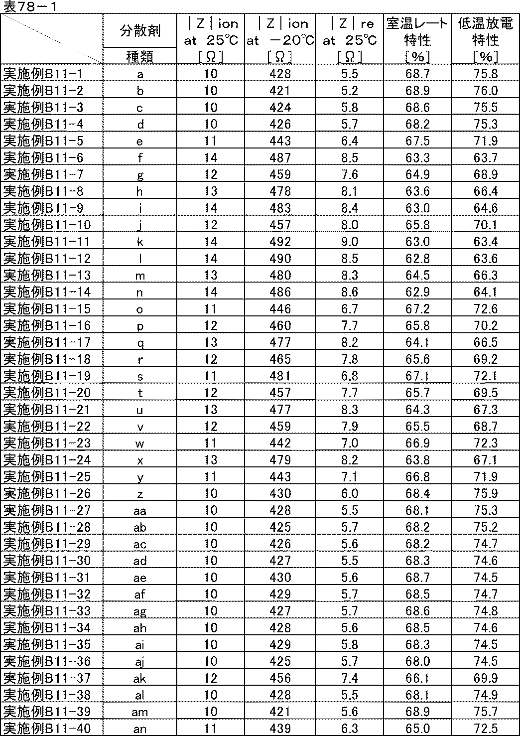
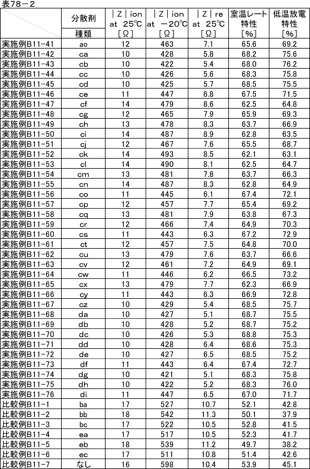
本発明の分散組成物を負極に用いた場合も、正極の場合と同じくイオン抵抗低減および反応抵抗低減効果が得られた。
[実施例B12-1]
<炭素材料分散液の調製>
表79に示す組成に従い、ガラス瓶に水と分散剤caを仕込み、混合した後、炭素材料を加え、ジルコニアビーズをメディアとして、ペイントコンディショナーで2時間分散し、炭素材料分散液を得た。
<炭素材料分散液の調製>
表79に示す組成に従い、ガラス瓶に水と分散剤caを仕込み、混合した後、炭素材料を加え、ジルコニアビーズをメディアとして、ペイントコンディショナーで2時間分散し、炭素材料分散液を得た。
<炭素材料分散ワニスの調製>
表79に示す組成に従い、調製した炭素材料分散液とバインダー、水をディスパーにて混合し、炭素材料分散ワニスを得た。
表79に示す組成に従い、調製した炭素材料分散液とバインダー、水をディスパーにて混合し、炭素材料分散ワニスを得た。
<合剤ペーストの調製>
表79に示す組成に従い、調製した炭素材料分散ワニスと活物質、水をディスパーにて混合し、正極合剤ペーストを得た。
表79に示す組成に従い、調製した炭素材料分散ワニスと活物質、水をディスパーにて混合し、正極合剤ペーストを得た。

<電極の作製>
<リチウムイオン二次電池正極評価用セルの組み立て>
実施例B3-1において、分散剤aを含む正極合剤ペーストの代わりに、分散剤caを含む正極合剤ペーストを用いた以外は、実施例B3-1と同様にして電極を作製し、正極評価用セルを組み立てた。
<リチウムイオン二次電池正極評価用セルの組み立て>
実施例B3-1において、分散剤aを含む正極合剤ペーストの代わりに、分散剤caを含む正極合剤ペーストを用いた以外は、実施例B3-1と同様にして電極を作製し、正極評価用セルを組み立てた。
[実施例B12-2~B12-35]
分散剤caを用いた代わりに、表80に示した分散剤cb~diをそれぞれ用いた以外は、実施例B12-1と同様な方法で分散し、正極評価用セルを組み立てた。
分散剤caを用いた代わりに、表80に示した分散剤cb~diをそれぞれ用いた以外は、実施例B12-1と同様な方法で分散し、正極評価用セルを組み立てた。
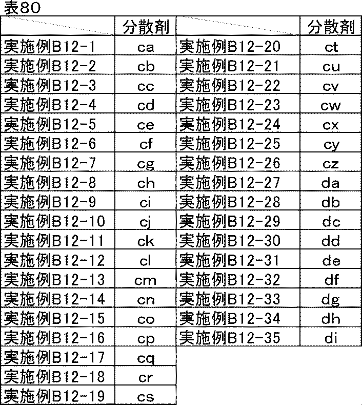
[比較例B12-1~B12-4]
表81に示した分散剤を用いて、実施例B12-1と同様な方法で分散し、正極評価用セルを組み立てた。比較例B12-4には分散剤を使用せず、その分の組成を水に振り替えた。
表81に示した分散剤を用いて、実施例B12-1と同様な方法で分散し、正極評価用セルを組み立てた。比較例B12-4には分散剤を使用せず、その分の組成を水に振り替えた。
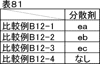
<評価結果>
実施例B12-1~B12-35、比較例B12-1~B12-3で調製した炭素材料分散液、炭素材料分散ワニス、正極合剤ペーストはいずれも良好な分散状態であり、1か月経時後も沈降や増粘はなかった。分散剤を使用していない比較例B12-4は初期から高粘度で粗大粒子が多かったが、そのまま比較用に用いた。1か月経時後はゲル状になっていた。
実施例B12-1~B12-35、比較例B12-1~B12-3で調製した炭素材料分散液、炭素材料分散ワニス、正極合剤ペーストはいずれも良好な分散状態であり、1か月経時後も沈降や増粘はなかった。分散剤を使用していない比較例B12-4は初期から高粘度で粗大粒子が多かったが、そのまま比較用に用いた。1か月経時後はゲル状になっていた。
実施例B12-1~B12-35、比較例B12-1~B12-4の正極評価用セルを用いて、実施例B3-1と同様な方法でイオン抵抗、反応抵抗、室温レート特性、低温放電特性の評価を行った。結果を表82に示す。
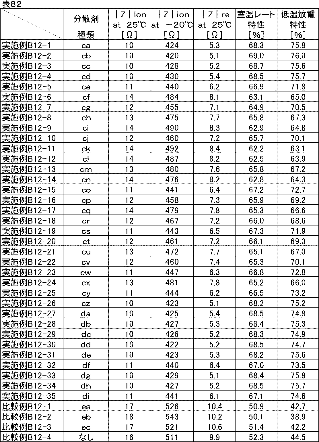
実施例B12-1~B12-35は、いずれの特性も優れており、溶剤を水とした場合でも同じ効果が得られることが確認できた。
[実施例B13-1~B13-8]ポリマー分散剤との併用-1
実施例B3-2で用いた分散剤bの半量を表83に示したポリマー分散剤に置き換えた以外は、実施例B3-2と同様にして炭素材料分散液、炭素材料分散ワニス、正極合剤ペースト、電極を作製し、正極評価用セルを組み立てた。
実施例B3-2で用いた分散剤bの半量を表83に示したポリマー分散剤に置き換えた以外は、実施例B3-2と同様にして炭素材料分散液、炭素材料分散ワニス、正極合剤ペースト、電極を作製し、正極評価用セルを組み立てた。
[比較例B13-1~B13-8]
比較例B3-1で用いた分散剤baの半量を表83に示したポリマー分散剤に置き換えた以外は、比較例B3-1と同様にして炭素材料分散液、炭素材料分散ワニス、正極合剤ペースト、電極を作製し、正極評価用セルを組み立てた。
比較例B3-1で用いた分散剤baの半量を表83に示したポリマー分散剤に置き換えた以外は、比較例B3-1と同様にして炭素材料分散液、炭素材料分散ワニス、正極合剤ペースト、電極を作製し、正極評価用セルを組み立てた。
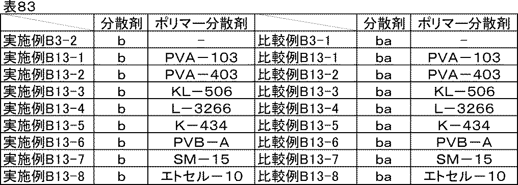
<剥離強度試験>
電極の剥離強度測定用の試験片は、塗工方向を長軸として90mm×20mmの長方形に2本カットして用いた。剥離強度の測定には卓上型引張試験機(東洋精機製作所製、ストログラフE3)を用い、180度剥離試験法により評価した。具体的には、100mm×30mmサイズの両面テープ(No.5000NS、ニトムズ(株)製)をステンレス板上に貼り付け、作製した電池電極合剤層を両面テープのもう一方の面に密着させ、一定速度(50mm/分)で下方から上方に引っ張りながら剥がし、このときの応力の平均値を剥離強度とした。剥離強度試験の結果は、◎:優れる、○:問題なし(良好)、△:〇よりは剥離強度が低いが問題なし(可)、×:強度が弱く、剥がれやすい(極めて不良)、とした。
電極の剥離強度測定用の試験片は、塗工方向を長軸として90mm×20mmの長方形に2本カットして用いた。剥離強度の測定には卓上型引張試験機(東洋精機製作所製、ストログラフE3)を用い、180度剥離試験法により評価した。具体的には、100mm×30mmサイズの両面テープ(No.5000NS、ニトムズ(株)製)をステンレス板上に貼り付け、作製した電池電極合剤層を両面テープのもう一方の面に密着させ、一定速度(50mm/分)で下方から上方に引っ張りながら剥がし、このときの応力の平均値を剥離強度とした。剥離強度試験の結果は、◎:優れる、○:問題なし(良好)、△:〇よりは剥離強度が低いが問題なし(可)、×:強度が弱く、剥がれやすい(極めて不良)、とした。
<評価結果>
実施例B13-1~B13-8、比較例B13-1~B13-8で調製した炭素材料分散液、炭素材料分散ワニス、正極合剤ペーストは、実施例B3-2や比較例B3-1と比較すると若干高粘度となったものの、いずれも良好な分散状態であり、1か月経時後も沈降や増粘はなかった。
実施例B13-1~B13-8、比較例B13-1~B13-8で調製した炭素材料分散液、炭素材料分散ワニス、正極合剤ペーストは、実施例B3-2や比較例B3-1と比較すると若干高粘度となったものの、いずれも良好な分散状態であり、1か月経時後も沈降や増粘はなかった。
実施例B3-2、実施例B13-1~B13-8、比較例B3-1、比較例B13-1~B13-8で作製した電極の剥離強度試験結果を表84に示す。分散剤baのみを用いた比較例B3-1と比較して、各種ポリマー分散剤を併用した比較例B13-1~B13-8は剥離強度がいずれも向上した。これは、膜形成能がない低分子の分散剤baの代わりに膜形成に関与できるポリマー成分が入ったことによって若干ではあるが向上したものによると考えられる。一方、分散剤bのみを用いた実施例B3-2と、各種ポリマー分散剤を併用した実施例B13-1~B13-8を比較すると、いずれも大幅な向上が見られた。
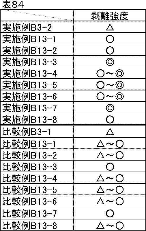
実施例B3-2、実施例B13-1~B13-8、比較例B3-1、比較例B13-1~13-8の正極評価用セルを用いて、実施例B3-1と同様な方法でイオン抵抗、反応抵抗、室温レート特性、低温放電特性の評価を行った。結果を表85に示す。
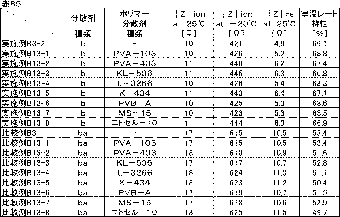
実施例B13-1~B13-8はいずれの特性も優れており、実施例B3-2と同等程度だった。本発明の分散剤とポリマー分散剤を併用することにより、優れた分散性や電池特性を維持したまま剥離強度を大幅に向上させることができた。比較例B13-1~B13-8は比較例B3-1に対して遜色ない程度であり、ポリマー分散剤を用いても電池特性にはほとんど影響しないことがわかった。
[実施例B13-9~B13-14]
剥離強度向上効果が本発明の他の分散剤でも得られるか確認するために、実施例B13-1~B13-8の剥離強度試験結果を参考に、特に効果が高かったKL-506およびSM-15を用いて同様に試験した。実施例B3-1、B3-3、B3-4でそれぞれ用いた分散剤a、c、dの半量を表86に示したポリマー分散剤に置き換えた以外は、実施例B13-1と同様にして炭素材料分散液、炭素材料分散ワニス、正極合剤ペースト、電極を作製し、正極評価用セルを組み立てた。
剥離強度向上効果が本発明の他の分散剤でも得られるか確認するために、実施例B13-1~B13-8の剥離強度試験結果を参考に、特に効果が高かったKL-506およびSM-15を用いて同様に試験した。実施例B3-1、B3-3、B3-4でそれぞれ用いた分散剤a、c、dの半量を表86に示したポリマー分散剤に置き換えた以外は、実施例B13-1と同様にして炭素材料分散液、炭素材料分散ワニス、正極合剤ペースト、電極を作製し、正極評価用セルを組み立てた。
[比較例B13-9~B13-12]
比較例B3-2、B3-3でそれぞれ用いた分散剤bb、bcの半量を表86に示したポリマー分散剤に置き換えた以外は、比較例B13-1と同様にして炭素材料分散液、炭素材料分散ワニス、正極合剤ペースト、電極を作製し、正極評価用セルを組み立てた。
比較例B3-2、B3-3でそれぞれ用いた分散剤bb、bcの半量を表86に示したポリマー分散剤に置き換えた以外は、比較例B13-1と同様にして炭素材料分散液、炭素材料分散ワニス、正極合剤ペースト、電極を作製し、正極評価用セルを組み立てた。

<評価結果>
実施例B3-1、B3-3、B3-4、実施例B13-9~B13-14、比較例B3-2、3-3、比較例B13-9~B13-12で作製した電極の剥離強度試験結果を表87に示す。分散剤baの場合と同様に、分散剤bb、bcと各種ポリマー分散剤を併用しても特異的な剥離強度向上はなかったが、分散剤a、c、dの場合は、分散剤bと同様に、各種ポリマー分散剤を併用することで特異的な剥離強度の向上が確認できた。さらに、本発明の他の分散剤を用いても同様の傾向であることを確認した。
実施例B3-1、B3-3、B3-4、実施例B13-9~B13-14、比較例B3-2、3-3、比較例B13-9~B13-12で作製した電極の剥離強度試験結果を表87に示す。分散剤baの場合と同様に、分散剤bb、bcと各種ポリマー分散剤を併用しても特異的な剥離強度向上はなかったが、分散剤a、c、dの場合は、分散剤bと同様に、各種ポリマー分散剤を併用することで特異的な剥離強度の向上が確認できた。さらに、本発明の他の分散剤を用いても同様の傾向であることを確認した。
この効果は本発明の分散剤に特有であることから、ひとつのトリアジン環に対して一般式(1)で表される-NH-R1と水酸基が2つ直結した構造によって、ポリマー分散剤との間に水素結合などの強い分子間力が作用したことによると考えられる。
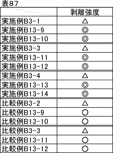
実施例B13-9~B13-14で作製した正極評価用セルのイオン抵抗、反応抵抗、室温レート特性、低温放電特性は、実施例B13-1~B13-8と同様に本発明の分散剤単独で用いた場合と同等程度に優れていた。一方、比較例B13-9~B13-12で作製した正極評価用セルのイオン抵抗、反応抵抗、室温レート特性、低温放電特性は比較例B13-1~B13-8と同様にポリマー分散剤を用いない場合と同程度でほとんど差異はなかった。
[実施例B13-15~B13-22]ポリマー分散剤との併用-2
実施例B3-43で用いた分散剤cbの半量を表88に示したポリマー分散剤に置き換えた以外は、それぞれ実施例B3-43と同様にして炭素材料分散液、炭素材料分散ワニス、正極合剤ペースト、電極を作製し、正極評価用セルを組み立てた。
実施例B3-43で用いた分散剤cbの半量を表88に示したポリマー分散剤に置き換えた以外は、それぞれ実施例B3-43と同様にして炭素材料分散液、炭素材料分散ワニス、正極合剤ペースト、電極を作製し、正極評価用セルを組み立てた。
[実施例B13-23~B13-30]ポリマー分散剤との併用-3
実施例B12-2で用いた分散剤cbの半量を表88に示したポリマー分散剤に置き換えた以外は、それぞれ実施例B12-2と同様にして炭素材料分散液、炭素材料分散ワニス、正極合剤ペースト、電極を作製し、正極評価用セルを組み立てた。
実施例B12-2で用いた分散剤cbの半量を表88に示したポリマー分散剤に置き換えた以外は、それぞれ実施例B12-2と同様にして炭素材料分散液、炭素材料分散ワニス、正極合剤ペースト、電極を作製し、正極評価用セルを組み立てた。
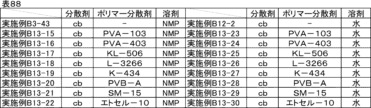
[比較例B13-13~B13-20]
比較例B3-4で用いた分散剤eaの半量を表89に示したポリマー分散剤に置き換えた以外は、それぞれ比較例B3-4と同様にして炭素材料分散液、炭素材料分散ワニス、正極合剤ペースト、電極を作製し、正極評価用セルを組み立てた。
比較例B3-4で用いた分散剤eaの半量を表89に示したポリマー分散剤に置き換えた以外は、それぞれ比較例B3-4と同様にして炭素材料分散液、炭素材料分散ワニス、正極合剤ペースト、電極を作製し、正極評価用セルを組み立てた。
[比較例B13-21~B13-28]
比較例B12-1で用いた分散剤eaの半量を表89に示したポリマー分散剤に置き換えた以外は、それぞれ比較例B12-1と同様にして炭素材料分散液、炭素材料分散ワニス、正極合剤ペースト、電極を作製し、正極評価用セルを組み立てた。
比較例B12-1で用いた分散剤eaの半量を表89に示したポリマー分散剤に置き換えた以外は、それぞれ比較例B12-1と同様にして炭素材料分散液、炭素材料分散ワニス、正極合剤ペースト、電極を作製し、正極評価用セルを組み立てた。
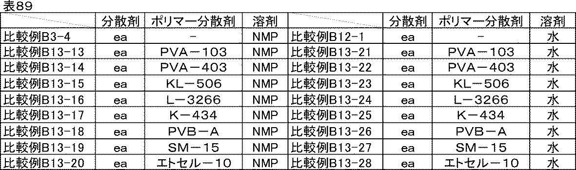
<評価結果>
実施例B3-43、B12-2、実施例B13-15~B13-30、比較例B3-4、比較例B12-1、比較例B13-13~B13-28の剥離強度試験結果を表90に示す。アミンか無機塩基かに係らず、また溶剤種が変わっても剥離強度の傾向は変わらなかった。したがって、この特異的な剥離強度向上効果は本発明のトリアジン誘導体構造に特有の現象であることが示唆された。
実施例B3-43、B12-2、実施例B13-15~B13-30、比較例B3-4、比較例B12-1、比較例B13-13~B13-28の剥離強度試験結果を表90に示す。アミンか無機塩基かに係らず、また溶剤種が変わっても剥離強度の傾向は変わらなかった。したがって、この特異的な剥離強度向上効果は本発明のトリアジン誘導体構造に特有の現象であることが示唆された。
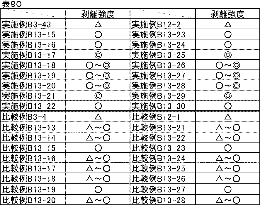
実施例B13-15~B13-30の正極評価用セルも同様に、ポリマー分散剤を用いない場合と同程度に優れたイオン抵抗、反応抵抗、室温レート特性、低温放電特性が得られた。一方、比較例B13-13~13-28の正極評価用セルは、やはりポリマー分散剤を用いない場合と同程度のイオン抵抗、反応抵抗、室温レート特性、低温放電特性であった。さらに、本発明の他の分散剤を用いても同様の傾向であることが確認できた。
次に、負極に対しても同様の剥離強度向上効果が得られるか確認するために、以下の試験を行った。
[実施例B14-1~B14-2]
実施例B11-2で用いた分散剤bの半量を表91に示したポリマー分散剤に置き換えた以外は、それぞれ実施例B11-2と同様にして炭素材料分散液、炭素材料分散ワニス、負極合剤ペースト、電極を作製し、負極評価用セルを組み立てた。
実施例B11-2で用いた分散剤bの半量を表91に示したポリマー分散剤に置き換えた以外は、それぞれ実施例B11-2と同様にして炭素材料分散液、炭素材料分散ワニス、負極合剤ペースト、電極を作製し、負極評価用セルを組み立てた。
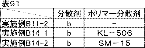
実施例B14-1、B14-2の負極評価用セルのイオン抵抗、反応抵抗、室温レート特性、低温放電特性は、実施例B11-2と同程度だった。また、剥離強度試験結果を47に示す。正極に用いた場合と同様に、分散剤bとポリマー分散剤を併用することで優れた電池特性を維持したまま大幅な剥離強度向上が確認できた。さらに、本発明の他の分散剤を用いても、また他のポリマー分散剤を用いても同様の傾向であることが確認できた。
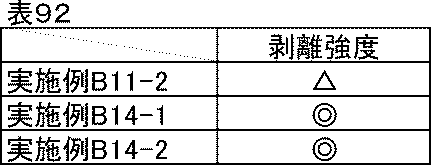
ポリマー分散剤2種との併用
[実施例B15-1]
続いて、ポリマー分散剤を2種類併用した場合の挙動を確認した。実施例B13-3で用いたKL-506のさらに半量をSM-15に置き換えた以外は、実施例B13-3と同様にして炭素材料分散液、炭素材料分散ワニス、正極合剤ペースト、電極を作製し、正極評価用セルを組み立てた。
[実施例B15-1]
続いて、ポリマー分散剤を2種類併用した場合の挙動を確認した。実施例B13-3で用いたKL-506のさらに半量をSM-15に置き換えた以外は、実施例B13-3と同様にして炭素材料分散液、炭素材料分散ワニス、正極合剤ペースト、電極を作製し、正極評価用セルを組み立てた。
[実施例B15-2]
実施例B13-17で用いたKL-506のさらに半量をSM-15に置き換えた以外は、実施例B13-17と同様にして炭素材料分散液、炭素材料分散ワニス、正極合剤ペースト、電極を作製し、正極評価用セルを組み立てた。
実施例B13-17で用いたKL-506のさらに半量をSM-15に置き換えた以外は、実施例B13-17と同様にして炭素材料分散液、炭素材料分散ワニス、正極合剤ペースト、電極を作製し、正極評価用セルを組み立てた。
[実施例B15-3]
実施例B13-25で用いたKL-506のさらに半量をSM-15に置き換えた以外は、実施例B13-25と同様にして炭素材料分散液、炭素材料分散ワニス、正極合剤ペースト、電極を作製し、正極評価用セルを組み立てた。
実施例B13-25で用いたKL-506のさらに半量をSM-15に置き換えた以外は、実施例B13-25と同様にして炭素材料分散液、炭素材料分散ワニス、正極合剤ペースト、電極を作製し、正極評価用セルを組み立てた。
実施例B15-1~B15-3の剥離強度試験結果を表93に示す。いずれも極めて良好であり、ポリマー分散剤を1種類用いた場合よりもさらに剥離強度が高かった。また、イオン抵抗、反応抵抗、室温レート特性、低温放電特性もいずれも優れていた。さらに本発明の他の分散剤を用いても、また他のポリマー分散剤と組み合わせた場合も同様の傾向であることを別途確認した。

以上の検証から、電極の加工性や長期サイクル中の剥がれが問題になる場合には、本発明の分散剤とポリマー分散剤とを組み合わせることで、本発明の効果を活かしながら補うことができる。また、大幅な剥離強度向上効果が得られることから、バインダーを減量して導電助剤や活物質を増やすこともでき、高出力化や高容量化など電池の使用目的に応じて設計することもできる。
[第3実施例群]
第3実施例群では、主に一般式(1)で表されるトリアジン誘導体を含む分散剤と、ポリマー分散剤との併用による効果を説明する。なお、第3実施例群において、実施例番号に「a」の添え字がある実施例は、ポリマー分散剤を有さない実施例である。
第3実施例群では、主に一般式(1)で表されるトリアジン誘導体を含む分散剤と、ポリマー分散剤との併用による効果を説明する。なお、第3実施例群において、実施例番号に「a」の添え字がある実施例は、ポリマー分散剤を有さない実施例である。
<トリアジン誘導体>
以下に本発明の一般式(1)で表わされるトリアジン誘導体A~Tの構造を示す。本発明に用いる一般式(1)で表わされるトリアジン誘導体A~Tの製造方法としては、特に限定されるものではなく、周知の方法を適用することができる。例えば、特開2004-217842号公報等に記載されている方法を適用することができる。上記公報による開示を参照することにより、本明細書の一部に組み込むものとする。
以下に本発明の一般式(1)で表わされるトリアジン誘導体A~Tの構造を示す。本発明に用いる一般式(1)で表わされるトリアジン誘導体A~Tの製造方法としては、特に限定されるものではなく、周知の方法を適用することができる。例えば、特開2004-217842号公報等に記載されている方法を適用することができる。上記公報による開示を参照することにより、本明細書の一部に組み込むものとする。

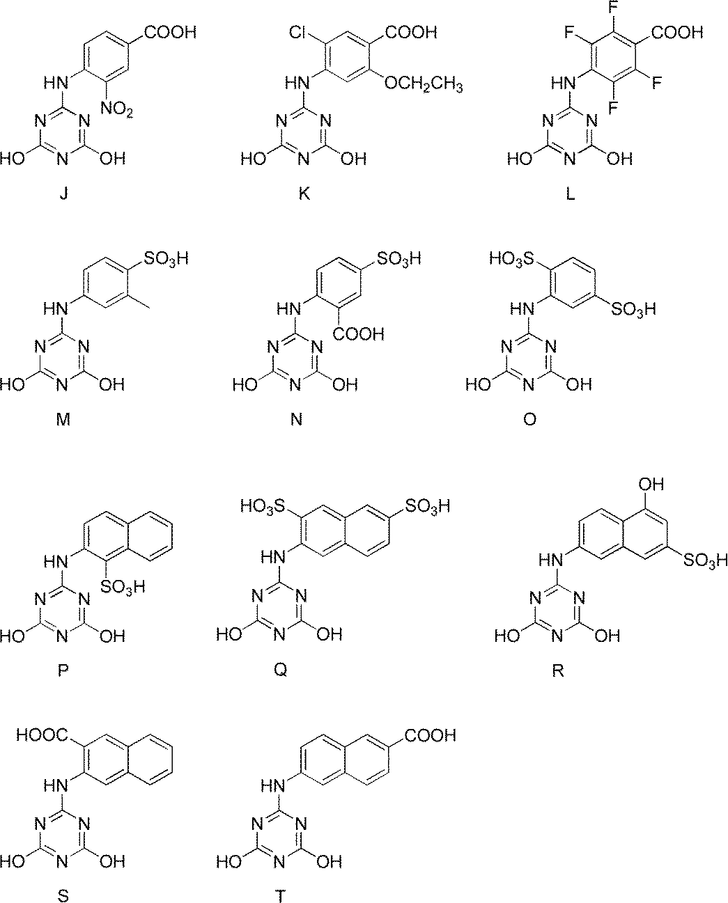
<トリアジン誘導体とアミンからなる分散剤の製造例>
以下の実施例に記載した方法で表94記載の分散剤a~ajを製造した。
以下の実施例に記載した方法で表94記載の分散剤a~ajを製造した。
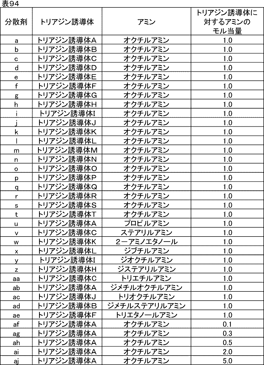
(分散剤aの製造)
水200gにトリアジン誘導体Aを0.040モル加えた。これにオクチルアミンを0.040モル加え、60℃で2時間撹拌した。室温まで冷却後、ろ過精製を行った。得られた残渣を90℃で48時間乾燥することにより、分散剤aを得た。
水200gにトリアジン誘導体Aを0.040モル加えた。これにオクチルアミンを0.040モル加え、60℃で2時間撹拌した。室温まで冷却後、ろ過精製を行った。得られた残渣を90℃で48時間乾燥することにより、分散剤aを得た。
(分散剤b~tの製造例)
分散剤aの製造においてトリアジン誘導体Aの代わりに表94に記載のトリアジン誘導体B~Tをそれぞれ添加した以外は、分散剤aと同様な方法で製造し、分散剤b~tを得た。
分散剤aの製造においてトリアジン誘導体Aの代わりに表94に記載のトリアジン誘導体B~Tをそれぞれ添加した以外は、分散剤aと同様な方法で製造し、分散剤b~tを得た。
(分散剤u~aeの製造例)
分散剤aの製造においてトリアジン誘導体Aの代わりに表94に記載のトリアジン誘導体をそれぞれ添加し、オクチルアミンの代わりに表94に記載のアミンをそれぞれ添加した以外は、分散剤aと同様な方法で製造し、分散剤u~aeを得た。
分散剤aの製造においてトリアジン誘導体Aの代わりに表94に記載のトリアジン誘導体をそれぞれ添加し、オクチルアミンの代わりに表94に記載のアミンをそれぞれ添加した以外は、分散剤aと同様な方法で製造し、分散剤u~aeを得た。
(分散剤af~ajの製造例)
分散剤aの製造においてオクチルアミンの添加量を表94に記載の添加量にそれぞれ変更した以外は分散剤aと同様な方法で製造し、分散剤af~ajを得た。
分散剤aの製造においてオクチルアミンの添加量を表94に記載の添加量にそれぞれ変更した以外は分散剤aと同様な方法で製造し、分散剤af~ajを得た。
以下に分散剤ba、bbで使用するトリアジン誘導体AA、ABの構造を示す。比較例に用いるトリアジン誘導体AA、ABの製造方法としては、特に限定されるものではなく、周知の方法を適用することができる。例えば、特開2004-217842号公報等に記載されている方法を適用することができる。上記公報による開示を参照することにより、本明細書の一部に組み込むものとする。
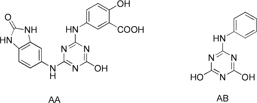
以下に記載した方法で表95記載の分散剤ba、bbを製造した。

(分散剤ba、bbの製造例)
分散剤aの製造においてトリアジン誘導体Aの代わりに表95に記載のトリアジン誘導体AA、ABをそれぞれ添加した以外は、分散剤aと同様な方法で製造し、分散剤ba、bbを得た。
分散剤aの製造においてトリアジン誘導体Aの代わりに表95に記載のトリアジン誘導体AA、ABをそれぞれ添加した以外は、分散剤aと同様な方法で製造し、分散剤ba、bbを得た。
<トリアジン誘導体と無機塩基とからなる分散剤の製造例>
以下に記載した方法で表96記載の分散剤ca~deを製造した。
以下に記載した方法で表96記載の分散剤ca~deを製造した。

(分散剤caの製造例)
水200gにトリアジン誘導体Aを0.040モル加えた。これに水酸化ナトリウムを0.020モル加え、60℃で2時間撹拌した。室温まで冷却後、ろ過精製を行った。得られた残渣を90℃で48時間乾燥することにより、分散剤caを得た。
水200gにトリアジン誘導体Aを0.040モル加えた。これに水酸化ナトリウムを0.020モル加え、60℃で2時間撹拌した。室温まで冷却後、ろ過精製を行った。得られた残渣を90℃で48時間乾燥することにより、分散剤caを得た。
(分散剤cb~ctの製造例)
分散剤caの製造においてトリアジン誘導体Aの代わりに表96に記載のトリアジン誘導体B~Tをそれぞれ添加した以外は、分散剤caと同様な方法で製造し、分散剤cb~ctを得た。
分散剤caの製造においてトリアジン誘導体Aの代わりに表96に記載のトリアジン誘導体B~Tをそれぞれ添加した以外は、分散剤caと同様な方法で製造し、分散剤cb~ctを得た。
(分散剤cu~daの製造例)
分散剤caの製造においてトリアジン誘導体Aの代わりに表96に記載のトリアジン誘導体をそれぞれ添加し、水酸化ナトリウムの代わりに表96に記載の無機塩基をそれぞれ添加した以外は、分散剤caと同様な方法で製造し、分散剤cu~daを得た。
分散剤caの製造においてトリアジン誘導体Aの代わりに表96に記載のトリアジン誘導体をそれぞれ添加し、水酸化ナトリウムの代わりに表96に記載の無機塩基をそれぞれ添加した以外は、分散剤caと同様な方法で製造し、分散剤cu~daを得た。
(分散剤db~deの製造例)
分散剤caの製造において水酸化ナトリウムの添加量を表96に記載の添加量にそれぞれ変更した以外は分散剤caと同様な方法で製造し、分散剤db~deを得た。
分散剤caの製造において水酸化ナトリウムの添加量を表96に記載の添加量にそれぞれ変更した以外は分散剤caと同様な方法で製造し、分散剤db~deを得た。
以下に記載した方法で表97記載の分散剤ea、ebを製造した。

(分散剤ea、ebの製造例)
分散剤caの製造においてトリアジン誘導体Aの代わりに表97に記載のトリアジン誘導体AA、ABをそれぞれ添加した以外は、分散剤caと同様な方法で製造し、分散剤ea、ebを得た。
分散剤caの製造においてトリアジン誘導体Aの代わりに表97に記載のトリアジン誘導体AA、ABをそれぞれ添加した以外は、分散剤caと同様な方法で製造し、分散剤ea、ebを得た。
[実施例C1-1]
<炭素材料分散液の調製>
表98に示す組成に従い、ガラス瓶にN-メチル-2-ピロリドンと分散剤aおよびポリマー分散剤PVA-103を仕込み、混合した後、炭素材料を加え、ジルコニアビーズをメディアとして、ペイントコンディショナーで2時間分散し、分散剤aとポリマー分散剤PVA-103を含む炭素材料分散液を得た。
<炭素材料分散液の調製>
表98に示す組成に従い、ガラス瓶にN-メチル-2-ピロリドンと分散剤aおよびポリマー分散剤PVA-103を仕込み、混合した後、炭素材料を加え、ジルコニアビーズをメディアとして、ペイントコンディショナーで2時間分散し、分散剤aとポリマー分散剤PVA-103を含む炭素材料分散液を得た。
<炭素材料分散ワニスの調製>
表98に示す組成に従い、調製した分散剤aとポリマー分散剤PVA-103を含む炭素材料分散液とバインダー、N-メチル-2-ピロリドンをディスパーにて混合し、炭素材料分散ワニスを得た。
表98に示す組成に従い、調製した分散剤aとポリマー分散剤PVA-103を含む炭素材料分散液とバインダー、N-メチル-2-ピロリドンをディスパーにて混合し、炭素材料分散ワニスを得た。
<正極合剤ペーストの調製>
表98に示す組成に従い、調製した分散剤aとポリマー分散剤PVA-103を含む炭素材料分散ワニスと活物質、N-メチル-2-ピロリドンをディスパーにて混合し、正極合剤ペーストを得た。
表98に示す組成に従い、調製した分散剤aとポリマー分散剤PVA-103を含む炭素材料分散ワニスと活物質、N-メチル-2-ピロリドンをディスパーにて混合し、正極合剤ペーストを得た。
<電極の作製>
調製した分散剤aとポリマー分散剤PVA-103を含む正極合剤ペーストを、厚さ20μmのアルミ箔上にドクターブレードを用いて塗工した後、減圧下120℃で30分間乾燥し、ローラープレス機にて圧延処理し、塗布量17mg/cm2、密度3.0g/cm3の電極を作製した。厚みや密度が均一な電極が得られた。
調製した分散剤aとポリマー分散剤PVA-103を含む正極合剤ペーストを、厚さ20μmのアルミ箔上にドクターブレードを用いて塗工した後、減圧下120℃で30分間乾燥し、ローラープレス機にて圧延処理し、塗布量17mg/cm2、密度3.0g/cm3の電極を作製した。厚みや密度が均一な電極が得られた。

[実施例C1-2~C1-10]
実施例C1-1で用いたポリマー分散剤PVA-103を表99に示したポリマー分散剤に置き換えた以外は、実施例C1-1と同様にして炭素材料分散液、炭素材料分散ワニス、正極合剤ペースト、電極を作製した。
実施例C1-1で用いたポリマー分散剤PVA-103を表99に示したポリマー分散剤に置き換えた以外は、実施例C1-1と同様にして炭素材料分散液、炭素材料分散ワニス、正極合剤ペースト、電極を作製した。
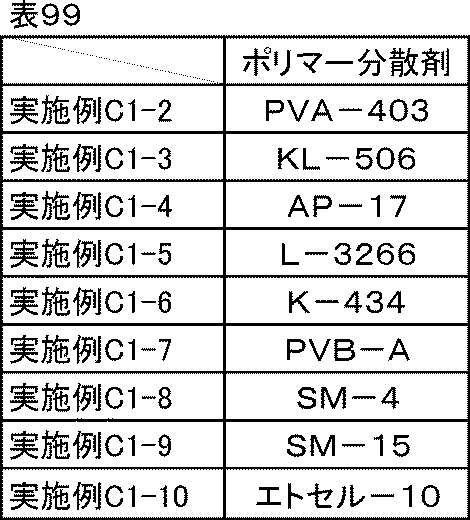
[実施例C1-1a]分散剤aのみ
表100に示す通り、実施例C1-1で用いたポリマー分散剤PVA-103を分散剤aに置き換えて分散剤を分散剤aのみとした以外は、実施例C1-1と同様にして炭素材料分散液、炭素材料分散ワニス、正極合剤ペースト、電極を作製した。
表100に示す通り、実施例C1-1で用いたポリマー分散剤PVA-103を分散剤aに置き換えて分散剤を分散剤aのみとした以外は、実施例C1-1と同様にして炭素材料分散液、炭素材料分散ワニス、正極合剤ペースト、電極を作製した。
[比較例C1-1]分散剤種の比較-1
表100に示す通り、実施例C1-1aで用いた分散剤aを分散剤baに置き換えた以外は、実施例C1-1aと同様にして炭素材料分散液、炭素材料分散ワニス、正極合剤ペースト、電極を作製した。
表100に示す通り、実施例C1-1aで用いた分散剤aを分散剤baに置き換えた以外は、実施例C1-1aと同様にして炭素材料分散液、炭素材料分散ワニス、正極合剤ペースト、電極を作製した。
[比較例C1-2]分散剤種の比較-2
表100に示す通り、実施例C1-1で用いた分散剤aを分散剤baに置き換えた以外は、実施例C1-1と同様にして炭素材料分散液、炭素材料分散ワニス、正極合剤ペースト、電極を作製した。
表100に示す通り、実施例C1-1で用いた分散剤aを分散剤baに置き換えた以外は、実施例C1-1と同様にして炭素材料分散液、炭素材料分散ワニス、正極合剤ペースト、電極を作製した。
[比較例C1-3、C1-4]分散剤種の比較-3
比較例C1-2で用いたPVA-103の代わりに、表100に示したポリマー分散剤をそれぞれ使用した以外は、比較例C1-2と同様にして炭素材料分散液、炭素材料分散ワニス、正極合剤ペースト、電極を作製した。
比較例C1-2で用いたPVA-103の代わりに、表100に示したポリマー分散剤をそれぞれ使用した以外は、比較例C1-2と同様にして炭素材料分散液、炭素材料分散ワニス、正極合剤ペースト、電極を作製した。

<剥離強度試験>
電極の剥離強度測定用の試験片は、塗工方向を長軸として90mm×20mmの長方形に2本カットして用いた。剥離強度の測定には卓上型引張試験機(東洋精機製作所社製、ストログラフE3)を用い、180度剥離試験法により評価した。具体的には、100mm×30mmサイズの両面テープ(No.5000NS、ニトムズ(株)製)をステンレス板上に貼り付け、作製した電池電極合剤層を両面テープのもう一方の面に密着させ、一定速度(50mm/分)で下方から上方に引っ張りながら剥がし、このときの応力の平均値を剥離強度とした。
電極の剥離強度測定用の試験片は、塗工方向を長軸として90mm×20mmの長方形に2本カットして用いた。剥離強度の測定には卓上型引張試験機(東洋精機製作所社製、ストログラフE3)を用い、180度剥離試験法により評価した。具体的には、100mm×30mmサイズの両面テープ(No.5000NS、ニトムズ(株)製)をステンレス板上に貼り付け、作製した電池電極合剤層を両面テープのもう一方の面に密着させ、一定速度(50mm/分)で下方から上方に引っ張りながら剥がし、このときの応力の平均値を剥離強度とした。
<評価結果>
実施例C1-1~C1-10、実施例C1-1a、比較例C1-1~C1-4で調製した炭素材料分散液、炭素材料分散ワニス、正極合剤ペーストは、いずれも良好な分散状態であり、1か月経時後も沈降や増粘はなかった。
実施例C1-1~C1-10、実施例C1-1a、比較例C1-1~C1-4で調製した炭素材料分散液、炭素材料分散ワニス、正極合剤ペーストは、いずれも良好な分散状態であり、1か月経時後も沈降や増粘はなかった。
実施例C1-1~C1-10、実施例C1-1a、比較例C1-1~C1-4で作製した電極の剥離強度試験結果を表101に示す。剥離強度試験の結果は、実施例C1-1aを100%としたとき、◎:200%以上、◎~○:200%未満175%以上、○:175%未満150%以上、○~△:150%未満120%以上、△:120%未満80%以上、とした。以下、正極合材において、溶剤がNMPである系の剥離強度試験の結果は、これに従うものとする。分散剤baのみを用いた比較例C1-1と比較して、各種ポリマー分散剤を併用した比較例C1-2~1-4は剥離強度がいずれも若干向上した。これは、膜形成能がない低分子の分散剤baの代わりに膜形成に関与できるポリマー成分が入ったことによって若干ではあるが向上したものによると考えられる。一方、各種ポリマー分散剤を併用した実施例C1-1~C1-10を比較すると、いずれも大幅な向上が見られた。比較例C1-1~C1-4の結果を考慮すると、実施例C1-1~C1-10で見られた効果は単に膜形成に関与できるポリマー成分が入ったことだけによるものではないと予想された。

[実施例C1-11~C1-188]
剥離強度向上効果が、一般式(1)で示される他のトリアジン誘導体でも得られるか確認するために、同様に試験を行った。実施例C1-1で使用した分散剤、ポリマー分散剤を表102に示した分散剤、ポリマー分散剤にそれぞれ置き換えた以外は、実施例C1-1と同様にして炭素材料分散液、炭素材料分散ワニス、正極合剤ペースト、電極を作製し、剥離強度試験を行った。
剥離強度向上効果が、一般式(1)で示される他のトリアジン誘導体でも得られるか確認するために、同様に試験を行った。実施例C1-1で使用した分散剤、ポリマー分散剤を表102に示した分散剤、ポリマー分散剤にそれぞれ置き換えた以外は、実施例C1-1と同様にして炭素材料分散液、炭素材料分散ワニス、正極合剤ペースト、電極を作製し、剥離強度試験を行った。

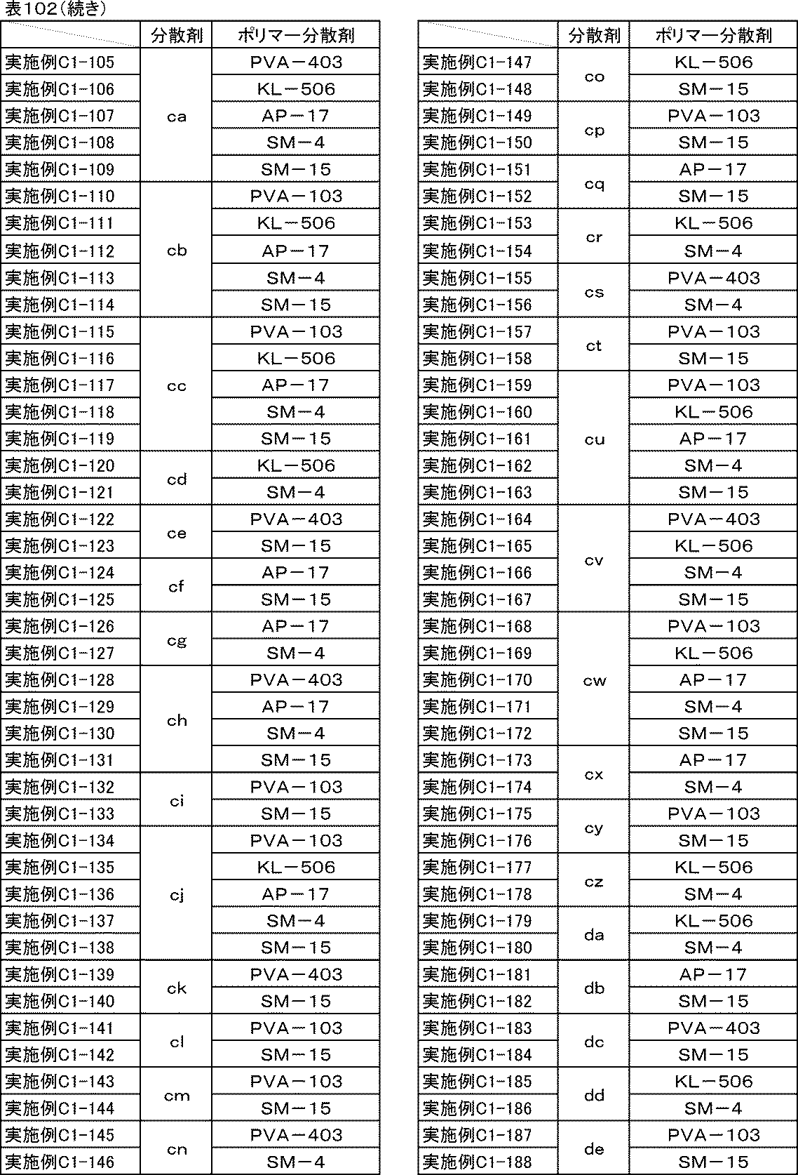
[参考例C1-189]トリアジン誘導体とポリマー分散剤の併用
表103に示す通り、実施例C1-1で用いた分散剤aをトリアジン誘導体Aに置き換えた以外は、実施例C1-1と同様にして炭素材料分散液、炭素材料分散ワニス、正極合剤ペースト、電極を作製し、剥離強度試験を行った。
表103に示す通り、実施例C1-1で用いた分散剤aをトリアジン誘導体Aに置き換えた以外は、実施例C1-1と同様にして炭素材料分散液、炭素材料分散ワニス、正極合剤ペースト、電極を作製し、剥離強度試験を行った。
[参考例C1-190~C1-193]トリアジン誘導体とポリマー分散剤の併用-2
参考例C1-189で用いたPVA-103の代わりに、表103に示したポリマー分散剤をそれぞれ使用し、トリアジン誘導体Aの代わりに表103に示したトリアジン誘導体をそれぞれ用いた以外は、参考例C1-189と同様にして炭素材料分散液、炭素材料分散ワニス、正極合剤ペースト、電極を作製し、剥離強度試験を行った。
参考例C1-189で用いたPVA-103の代わりに、表103に示したポリマー分散剤をそれぞれ使用し、トリアジン誘導体Aの代わりに表103に示したトリアジン誘導体をそれぞれ用いた以外は、参考例C1-189と同様にして炭素材料分散液、炭素材料分散ワニス、正極合剤ペースト、電極を作製し、剥離強度試験を行った。
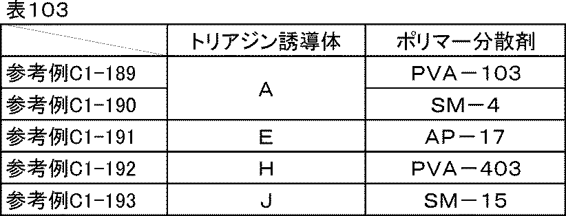
[実施例C1-194]ポリマー分散剤の併用
表104に示す通り、実施例C1-1で用いたPVA-103のさらに半量をSM-15に置き換えた以外は、実施例C1-1と同様にして炭素材料分散液、炭素材料分散ワニス、正極合剤ペースト、電極を作製し、剥離強度試験を行った。
表104に示す通り、実施例C1-1で用いたPVA-103のさらに半量をSM-15に置き換えた以外は、実施例C1-1と同様にして炭素材料分散液、炭素材料分散ワニス、正極合剤ペースト、電極を作製し、剥離強度試験を行った。
[実施例C1-195、C1-196]ポリマー分散剤の併用-2
実施例C1-194で用いたPVA-103の代わりに、表104に示したポリマー分散剤をそれぞれ使用した以外は、実施例C1-194と同様にして炭素材料分散液、炭素材料分散ワニス、正極合剤ペースト、電極を作製し、剥離強度試験を行った。
実施例C1-194で用いたPVA-103の代わりに、表104に示したポリマー分散剤をそれぞれ使用した以外は、実施例C1-194と同様にして炭素材料分散液、炭素材料分散ワニス、正極合剤ペースト、電極を作製し、剥離強度試験を行った。
[参考例C1-197~C1-199]ポリマー分散剤の併用-3
実施例C1-194で用いたPVA-103の代わりに、表104に示したポリマー分散剤をそれぞれ使用し、分散剤aの代わりにトリアジン誘導体Aを用いた以外は、実施例C1-194と同様にして炭素材料分散液、炭素材料分散ワニス、正極合剤ペースト、電極を作製し、剥離強度試験を行った。
実施例C1-194で用いたPVA-103の代わりに、表104に示したポリマー分散剤をそれぞれ使用し、分散剤aの代わりにトリアジン誘導体Aを用いた以外は、実施例C1-194と同様にして炭素材料分散液、炭素材料分散ワニス、正極合剤ペースト、電極を作製し、剥離強度試験を行った。

[比較例C1-5~C1-7]
実施例C1-1aで用いた分散剤aを表105で示した分散剤に置き換えた以外は、実施例C1-1aと同様にして炭素材料分散液、炭素材料分散ワニス、正極合剤ペースト、電極を作製し、剥離強度試験を行った。
実施例C1-1aで用いた分散剤aを表105で示した分散剤に置き換えた以外は、実施例C1-1aと同様にして炭素材料分散液、炭素材料分散ワニス、正極合剤ペースト、電極を作製し、剥離強度試験を行った。

[比較例C1-8~C1-13]
実施例C1-1で使用した分散剤a、ポリマー分散剤PVA-103を表106に示した分散剤、ポリマー分散剤にそれぞれ置き換えた以外は、実施例C1-1と同様にして炭素材料分散液、炭素材料分散ワニス、正極合剤ペースト、電極を作製し、剥離強度試験を行った。
実施例C1-1で使用した分散剤a、ポリマー分散剤PVA-103を表106に示した分散剤、ポリマー分散剤にそれぞれ置き換えた以外は、実施例C1-1と同様にして炭素材料分散液、炭素材料分散ワニス、正極合剤ペースト、電極を作製し、剥離強度試験を行った。
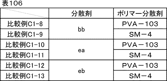
<評価結果>
実施例C1-11~C1-188、実施例C1-194~C1-199、参考例C1-1a、参考例C1-189~C1-193、参考例C1-197~C1-199、比較例C1-5~C1-13で作製した電極の剥離強度試験結果を表107に示す。分散剤baの場合と同様に、分散剤bb、ea、ebと各種ポリマー分散剤を併用しても若干の剥離強度向上しかしなかったが、分散剤b~aj、ca~de、トリアジン誘導体A、E、H、Jの場合は、分散剤aと同様に、各種ポリマー分散剤1種または2種を併用することで大幅な剥離強度の向上が確認できた。
実施例C1-11~C1-188、実施例C1-194~C1-199、参考例C1-1a、参考例C1-189~C1-193、参考例C1-197~C1-199、比較例C1-5~C1-13で作製した電極の剥離強度試験結果を表107に示す。分散剤baの場合と同様に、分散剤bb、ea、ebと各種ポリマー分散剤を併用しても若干の剥離強度向上しかしなかったが、分散剤b~aj、ca~de、トリアジン誘導体A、E、H、Jの場合は、分散剤aと同様に、各種ポリマー分散剤1種または2種を併用することで大幅な剥離強度の向上が確認できた。
この効果は一般式(1)で示されるトリアジン誘導体に特有であることから、酸性官能基を有するアリーレン基と、フェノール性水酸基2つがひとつのトリアジン環に直結している構造によって、ポリマー分散剤との間に水素結合などの強い分子間力が作用したことによると考えられる。
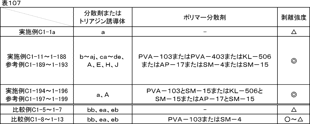
続いてリチウムイオン二次電池正極評価用のセルを組み立て、イオン抵抗、反応抵抗、室温レート特性、低温放電特性、サイクル特性の評価を行った。
[実施例C2-1]
<リチウムイオン二次電池正極評価用セルの組み立て>
実施例C1-1で作製した分散剤aを含む電極を直径16mmに打ち抜き正極とし、金属リチウム箔(厚さ0.15mm)を負極として、正極および負極の間に多孔質ポリプロピレンフィルムからなるセパレーター(厚さ20μm、空孔率50%)を挿入積層し、電解液(エチレンカーボネートとジエチルカーボネートを体積比1:1に混合した混合溶媒にLiPF6を1Mの濃度で溶解させた非水電解液)を0.1ml満たして二極密閉式金属セル(宝泉社製HSフラットセル)を組み立てた。セルの組み立てはアルゴンガス置換したグローブボックス内で行った。
<リチウムイオン二次電池正極評価用セルの組み立て>
実施例C1-1で作製した分散剤aを含む電極を直径16mmに打ち抜き正極とし、金属リチウム箔(厚さ0.15mm)を負極として、正極および負極の間に多孔質ポリプロピレンフィルムからなるセパレーター(厚さ20μm、空孔率50%)を挿入積層し、電解液(エチレンカーボネートとジエチルカーボネートを体積比1:1に混合した混合溶媒にLiPF6を1Mの濃度で溶解させた非水電解液)を0.1ml満たして二極密閉式金属セル(宝泉社製HSフラットセル)を組み立てた。セルの組み立てはアルゴンガス置換したグローブボックス内で行った。
<イオン抵抗評価>
実施例C2-1で組み立てた正極評価用セルを-20℃の恒温槽内で12時間静置し、開回路電位にて周波数0.1Hz、振幅10mVで交流インピーダンス測定を行い、イオン抵抗|Z|ionを求めた。続いて正極評価用セルを室温(25℃)に移して3時間静置し、同様にインピーダンス測定を行い、イオン抵抗|Z|ionを求めた。測定にはインピーダンスアナライザーを用いた。
実施例C2-1で組み立てた正極評価用セルを-20℃の恒温槽内で12時間静置し、開回路電位にて周波数0.1Hz、振幅10mVで交流インピーダンス測定を行い、イオン抵抗|Z|ionを求めた。続いて正極評価用セルを室温(25℃)に移して3時間静置し、同様にインピーダンス測定を行い、イオン抵抗|Z|ionを求めた。測定にはインピーダンスアナライザーを用いた。
<反応抵抗評価>
イオン抵抗評価に続いて、充放電測定装置を用い、室温にて0.1Cの定電流定電圧充電(上限電圧4.2V)で満充電とし、0.1Cの定電流で放電下限電圧3.0Vまで放電を行う充放電を1サイクルとして合計5サイクル行った。5サイクル目の0.1C放電容量を記録しておいた。次に、3.0Vまで放電した状態の正極評価用セルをインピーダンスアナライザーに接続し、3.0V、振幅10mV、周波数0.1Hzから1MHzにおいて交流インピーダンス測定を行った。結果をコールコールプロット法にて複素平面上にプロットすると、半円状の曲線が得られる。この円弧の直径を活物質の反応抵抗|Z|reとした。
イオン抵抗評価に続いて、充放電測定装置を用い、室温にて0.1Cの定電流定電圧充電(上限電圧4.2V)で満充電とし、0.1Cの定電流で放電下限電圧3.0Vまで放電を行う充放電を1サイクルとして合計5サイクル行った。5サイクル目の0.1C放電容量を記録しておいた。次に、3.0Vまで放電した状態の正極評価用セルをインピーダンスアナライザーに接続し、3.0V、振幅10mV、周波数0.1Hzから1MHzにおいて交流インピーダンス測定を行った。結果をコールコールプロット法にて複素平面上にプロットすると、半円状の曲線が得られる。この円弧の直径を活物質の反応抵抗|Z|reとした。
<室温レート特性・低温放電特性評価>
次に、室温にて0.1Cで同様に満充電にした後、0.5Cの定電流で放電下限電圧3.0Vまで放電し、再度0.1Cで満充電にしてから5Cの定電流で3.0Vまで放電した。反応抵抗評価の試験で記録しておいた5サイクル目の0.1C放電容量に対する5C放電容量の比率を、室温レート特性(%)とした。またここで、室温における0.5C放電容量を記録しておいた。続いて、室温、0.1Cで同様に満充電にしてから-20℃の恒温槽内に移して12時間静置した後に、0.5Cの定電流で同じく放電した。室温の0.5C放電容量に対する-20℃の0.5C放電容量の比率を、低温放電特性(%)とした。室温レート特性、低温放電特性共に100%に近いほど良好である。
次に、室温にて0.1Cで同様に満充電にした後、0.5Cの定電流で放電下限電圧3.0Vまで放電し、再度0.1Cで満充電にしてから5Cの定電流で3.0Vまで放電した。反応抵抗評価の試験で記録しておいた5サイクル目の0.1C放電容量に対する5C放電容量の比率を、室温レート特性(%)とした。またここで、室温における0.5C放電容量を記録しておいた。続いて、室温、0.1Cで同様に満充電にしてから-20℃の恒温槽内に移して12時間静置した後に、0.5Cの定電流で同じく放電した。室温の0.5C放電容量に対する-20℃の0.5C放電容量の比率を、低温放電特性(%)とした。室温レート特性、低温放電特性共に100%に近いほど良好である。
<サイクル特性評価>
次に、室温で12時間放置し、1Cの定電流定電圧充電(上限電圧4.3V)で満充電として、1Cの定電流で3.0Vまで放電した。これを1サイクルとして500サイクル繰り返し、1サイクル目の放電容量に対する500サイクル目の放電容量の比率をサイクル特性(%)とした。サイクル特性評価は100%に近いほど良好である。
次に、室温で12時間放置し、1Cの定電流定電圧充電(上限電圧4.3V)で満充電として、1Cの定電流で3.0Vまで放電した。これを1サイクルとして500サイクル繰り返し、1サイクル目の放電容量に対する500サイクル目の放電容量の比率をサイクル特性(%)とした。サイクル特性評価は100%に近いほど良好である。
[実施例C2-2~C2-188、実施例C2-194~C2-196][参考例C2-189~C2-193、参考例C2-197~C2-199]
実施例C2-1において、実施例C1-1で作製した電極を用いた代わりに、表108に示した電極をそれぞれ用いた以外は、実施例C2-1と同様の方法でリチウムイオン二次電池正極評価用のセルを組み立て、イオン抵抗、反応抵抗、室温レート特性、低温放電特性、サイクル特性の評価を行った。
実施例C2-1において、実施例C1-1で作製した電極を用いた代わりに、表108に示した電極をそれぞれ用いた以外は、実施例C2-1と同様の方法でリチウムイオン二次電池正極評価用のセルを組み立て、イオン抵抗、反応抵抗、室温レート特性、低温放電特性、サイクル特性の評価を行った。


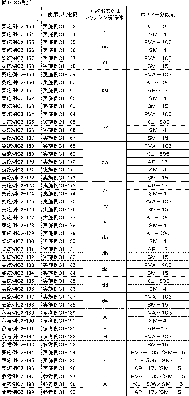
[比較例C2-1~C2-4][実施例C2-1a]
実施例C2-1において、実施例C1-1で作製した電極を用いた代わりに、表109に示した電極をそれぞれ用いた以外は、実施例C2-1と同様の方法でリチウムイオン二次電池正極評価用のセルを組み立て、イオン抵抗、反応抵抗、室温レート特性、低温放電特性、サイクル特性の評価を行った。
実施例C2-1において、実施例C1-1で作製した電極を用いた代わりに、表109に示した電極をそれぞれ用いた以外は、実施例C2-1と同様の方法でリチウムイオン二次電池正極評価用のセルを組み立て、イオン抵抗、反応抵抗、室温レート特性、低温放電特性、サイクル特性の評価を行った。
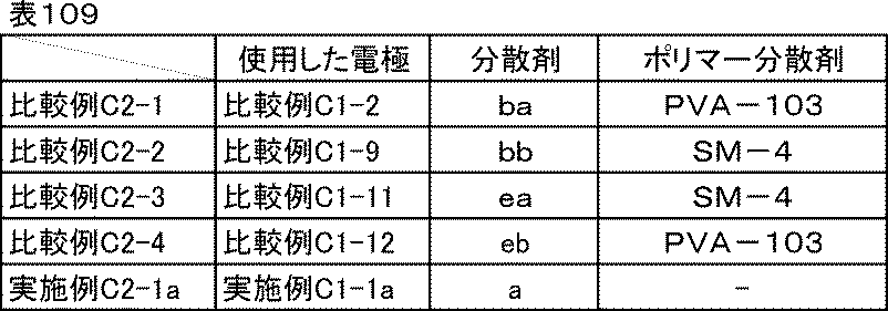
[比較例C2-5]
実施例C1-1で使用した分散剤a、ポリマー分散剤PVA-103を溶剤に置き換えた以外は、実施例C1-1と同様にして炭素材料分散液、炭素材料分散ワニス、正極合剤ペースト、電極を作製した。その電極を、実施例C1-1で作製した電極の代わりに使用し、実施例C2-1と同様の方法でリチウムイオン二次電池正極評価用のセルを組み立て、イオン抵抗、反応抵抗、室温レート特性、低温放電特性、サイクル特性の評価を行った。
実施例C1-1で使用した分散剤a、ポリマー分散剤PVA-103を溶剤に置き換えた以外は、実施例C1-1と同様にして炭素材料分散液、炭素材料分散ワニス、正極合剤ペースト、電極を作製した。その電極を、実施例C1-1で作製した電極の代わりに使用し、実施例C2-1と同様の方法でリチウムイオン二次電池正極評価用のセルを組み立て、イオン抵抗、反応抵抗、室温レート特性、低温放電特性、サイクル特性の評価を行った。
<評価結果>
実施例C2-1~C2-104のイオン抵抗、反応抵抗、室温レート特性、低温放電特性、サイクル特性の評価結果を表110に、実施例C2-105~C2-188、参考例C2-189~C2-193、実施例C2-194~C2-196、参考例C2-197~C2-199のイオン抵抗、反応抵抗、室温レート特性、低温放電特性、サイクル特性の評価結果を表111に、比較例C2-1~C2-5、実施例C2-1aのイオン抵抗、反応抵抗、室温レート特性、低温放電特性、サイクル特性の結果を表112に示す。
実施例C2-1~C2-104のイオン抵抗、反応抵抗、室温レート特性、低温放電特性、サイクル特性の評価結果を表110に、実施例C2-105~C2-188、参考例C2-189~C2-193、実施例C2-194~C2-196、参考例C2-197~C2-199のイオン抵抗、反応抵抗、室温レート特性、低温放電特性、サイクル特性の評価結果を表111に、比較例C2-1~C2-5、実施例C2-1aのイオン抵抗、反応抵抗、室温レート特性、低温放電特性、サイクル特性の結果を表112に示す。


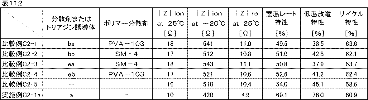
表110、表111、表112からわかる通り、分散剤a~aj、ca~de、トリアジン誘導体A、E、H、Jを用いた実施例C2-1~C2-188、参考例C2-189~C2-193、実施例C2-194~C2-196、参考例C2-197~C2-199、実施例C2-1aの正極は室温および-20℃のイオン抵抗、反応抵抗、室温レート特性、低温放電特性の全てにおいて、分散剤ba、bb、ea、ebとポリマー分散剤を用いた比較例C2-1~C2-4や分散剤を用いない比較例C2-5の正極と比べて非常に優れていた。
分散剤a~aj、ca~deは、極めて電子密度の高いLi+が近傍に存在することで、誘電分極を生じ、電池内では高い誘電率で存在していると考えられる。これによりイオン伝導度を向上させたり、活物質とLiが反応する際のLi+の脱溶媒和エネルギーや溶媒和エネルギーを低減させ、結果としてイオン抵抗および反応抵抗が小さくなって、電池全体としても特性が向上すると思われる。
また、分散剤a~aj、ca~deとポリマー分散剤を用いた実施例C2-1~2-199の正極は、分散剤ba、bb、ea、ebとポリマー分散剤を用いた比較例C2-1~C2-4や分散剤を用いない比較例C2-5の正極と比べてサイクル特性が大幅に向上した。
実施例と比較例、参考例の正極評価用セルを解体して電極の状態を確認したところ、参考例と比較例の電極は一部剥がれやひび割れが発生していたのに対し、実施例の電極は良好な状態であった。剥離強度が大幅に向上したことによって、サイクルによる電極の剥がれや劣化が抑制され、サイクル特性が向上したものと考えられる。
[実施例C3-1~C3-10][比較例C3-1~C3-5]炭素材料種の比較
表113に示した炭素材料分散液、表114に示した炭素材料分散ワニス、表115に示した正極合剤ペーストの材料と組成に従い、実施例C1-1と同様にして炭素材料分散液、炭素材料分散ワニス、正極合剤ペースト、電極をそれぞれ作製し、剥離強度試験を行った。たその電極を、実施例C2-1において実施例C1-1で作製した電極を用いた代わりにそれぞれ使用し、実施例C2-1と同様の方法でリチウムイオン二次電池正極評価用のセルを組み立て、イオン抵抗、反応抵抗、室温レート特性、低温放電特性、サイクル特性の評価を行った。高比表面積の炭素材料に対しては分散剤が多く必要であるため、それぞれの炭素材料に合わせて適宜使用量を決定した。
表113に示した炭素材料分散液、表114に示した炭素材料分散ワニス、表115に示した正極合剤ペーストの材料と組成に従い、実施例C1-1と同様にして炭素材料分散液、炭素材料分散ワニス、正極合剤ペースト、電極をそれぞれ作製し、剥離強度試験を行った。たその電極を、実施例C2-1において実施例C1-1で作製した電極を用いた代わりにそれぞれ使用し、実施例C2-1と同様の方法でリチウムイオン二次電池正極評価用のセルを組み立て、イオン抵抗、反応抵抗、室温レート特性、低温放電特性、サイクル特性の評価を行った。高比表面積の炭素材料に対しては分散剤が多く必要であるため、それぞれの炭素材料に合わせて適宜使用量を決定した。
(炭素材料分散液の組成)
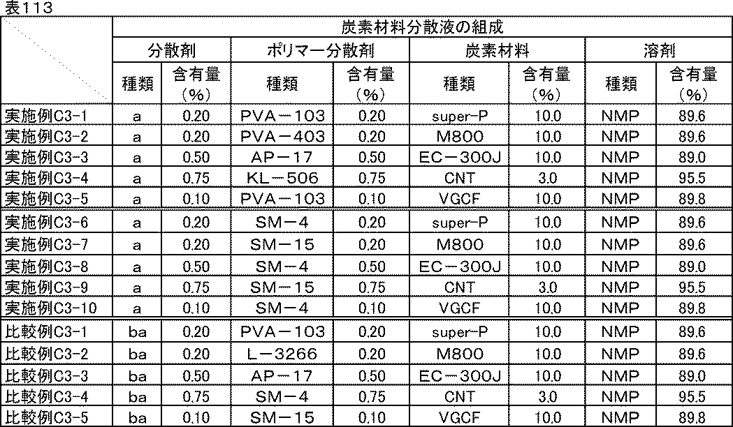
(炭素材料分散ワニスの組成)

(正極合剤ペーストの組成)
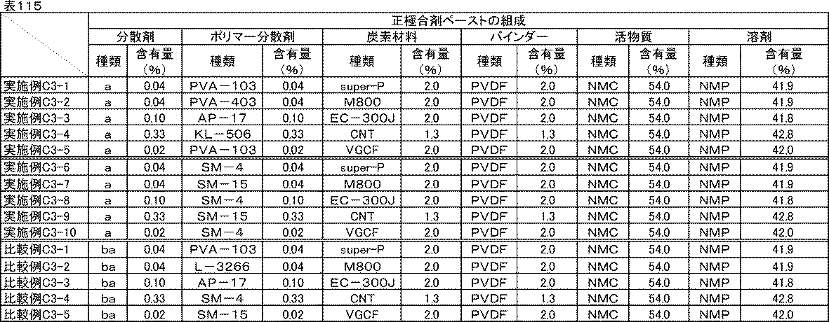
<評価結果>
いずれの実施例、比較例に記載の炭素材料分散液、炭素材料分散ワニス、正極合剤ペーストも良好な分散状態であり、1か月経時後も沈降や増粘はなかった。
いずれの実施例、比較例に記載の炭素材料分散液、炭素材料分散ワニス、正極合剤ペーストも良好な分散状態であり、1か月経時後も沈降や増粘はなかった。
実施例C3-1~C3-10、比較例C3-1~C3-5の正極評価用セルのイオン抵抗、反応抵抗、室温レート特性、低温放電特性、サイクル特性、剥離強度の評価結果を表116に示す。

いずれの炭素材料であっても同様の効果が確認できた。実施例C3-1~C3-10の差異は炭素材料の導電性による差異であると考えられる。また、比較例C3-1~C3-5では、分散剤の添加量が多いものほどいずれの特性も悪い傾向にあった。
以上の検証から、先に述べた効果は炭素材料種によらないことが確認できた。
[実施例C4-1~C4-12]活物質表面積あたりの分散剤量の比較-1
実施例C1-2において、用いた分散剤の量、およびポリマー分散剤の量の代わりに、表117、表118、表119に示す分散剤量とした以外は実施例C1-2と同様にして電極を作製した。その電極を、実施例C2-2において実施例C1-2で作製した電極を用いた代わりにそれぞれ使用し、実施例C2-2と同様の方法でリチウムイオン二次電池正極評価用のセルを組み立て、イオン抵抗、反応抵抗、室温レート特性、低温放電特性の評価を行った。電極中の活物質表面積1m2に対する分散剤量(mg)を表120に示した。
実施例C1-2において、用いた分散剤の量、およびポリマー分散剤の量の代わりに、表117、表118、表119に示す分散剤量とした以外は実施例C1-2と同様にして電極を作製した。その電極を、実施例C2-2において実施例C1-2で作製した電極を用いた代わりにそれぞれ使用し、実施例C2-2と同様の方法でリチウムイオン二次電池正極評価用のセルを組み立て、イオン抵抗、反応抵抗、室温レート特性、低温放電特性の評価を行った。電極中の活物質表面積1m2に対する分散剤量(mg)を表120に示した。
(炭素材料分散液の組成)

(炭素材料分散ワニスの組成)
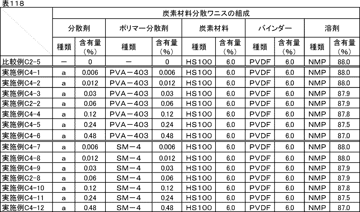
(正極合剤ペーストの組成)
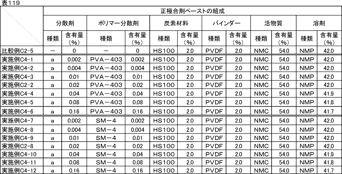
(活物質表面積あたりの分散剤量)

<評価結果>
比較例C2-5、実施例C2-2、C2-8、C4-1~C4-12の反応抵抗、室温レート特性、低温放電特性の評価結果を表121に示す。
比較例C2-5、実施例C2-2、C2-8、C4-1~C4-12の反応抵抗、室温レート特性、低温放電特性の評価結果を表121に示す。

実施例C4-1から、活物質表面積に対する分散剤量が少なすぎると効果が小さくなることがわかった。実施例C4-2、C4-8の分散剤量以上で特に大きな効果が得られるようになり、分散剤量が増えるにつれて徐々に良化した。
[実施例C5-1~C5-18]活物質表面積あたりの分散剤量の比較-2
表122、表123、表124に示す材料、組成にて実施例C1-1と同様に分散し、正極評価用セルを組み立て、イオン抵抗、反応抵抗、室温レート特性、低温放電特性の評価を行った。電極中の活物質表面積1m2に対する分散剤量(mg)を表125に示した。
表122、表123、表124に示す材料、組成にて実施例C1-1と同様に分散し、正極評価用セルを組み立て、イオン抵抗、反応抵抗、室温レート特性、低温放電特性の評価を行った。電極中の活物質表面積1m2に対する分散剤量(mg)を表125に示した。
(炭素材料分散液の組成)

(炭素材料分散ワニスの組成)
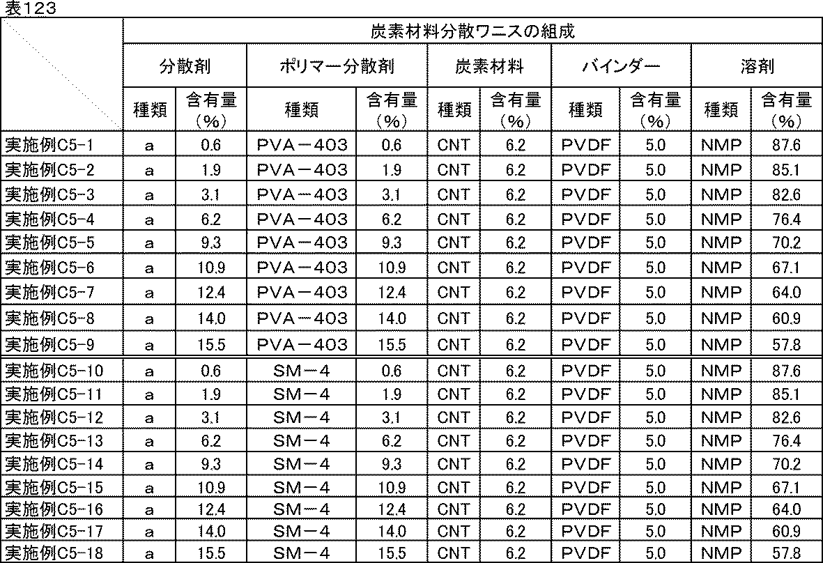
(正極合剤ペーストの組成)
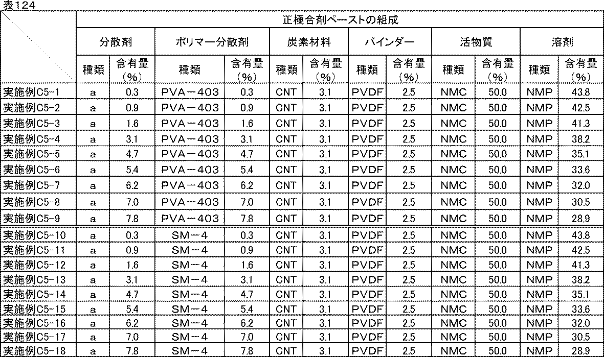
(活物質表面積あたりの分散剤量)

<評価結果>
実施例C5-1~5-18の反応抵抗、室温レート特性、低温放電特性の評価結果を表126に示す。
実施例C5-1~5-18の反応抵抗、室温レート特性、低温放電特性の評価結果を表126に示す。

表126より、実施例C5-7、C5-16の分散剤量を超えると反応抵抗低減効果が小さくなることがわかった。分散剤量が過剰になると、脱溶媒和エネルギーの低減以上に抵抗成分としての悪影響が大きくなることによると考えられる。
以上のことから、より大きな反応抵抗低減効果を得るためには、活物質表面積に対する分散剤添加量の最適な範囲が存在することがわかった。
[実施例C6-1~C6-12]電解液量に対する分散剤量の比較-1
実施例C4-2、C4-8で作製した正極を用いて、表127に示す電解液の量に変更した以外は、実施例C4-2、C4-8と同様に正極評価用セルを組み立て、イオン抵抗、反応抵抗、室温レート特性、低温放電特性の評価を行った。
実施例C4-2、C4-8で作製した正極を用いて、表127に示す電解液の量に変更した以外は、実施例C4-2、C4-8と同様に正極評価用セルを組み立て、イオン抵抗、反応抵抗、室温レート特性、低温放電特性の評価を行った。

[実施例C7-1~C7-14]電解液量に対する分散剤量の比較-2
実施例C5-3、C5-12で作製した正極合剤ペーストを用いて、塗布量を28mg/cm2に変更した以外は実施例C5-3と同様な方法で正極を作製した。さらに、正極評価用セルに添加する電解液の量を表128に示す量に変更し、それ以外は実施例C5-3、5-12と同様に正極評価用セルを組み立て、イオン抵抗、反応抵抗、室温レート特性、低温放電特性の評価を行った。
実施例C5-3、C5-12で作製した正極合剤ペーストを用いて、塗布量を28mg/cm2に変更した以外は実施例C5-3と同様な方法で正極を作製した。さらに、正極評価用セルに添加する電解液の量を表128に示す量に変更し、それ以外は実施例C5-3、5-12と同様に正極評価用セルを組み立て、イオン抵抗、反応抵抗、室温レート特性、低温放電特性の評価を行った。

<評価結果>
実施例C4-2、実施例C6-1~C6-12、比較例C2-5のイオン抵抗、反応抵抗、室温レート特性、低温放電特性の評価結果を表129に示す。実施例C7-1~C7-14のイオン抵抗、反応抵抗、室温レート特性、低温放電特性の評価結果を表130に示す。
実施例C4-2、実施例C6-1~C6-12、比較例C2-5のイオン抵抗、反応抵抗、室温レート特性、低温放電特性の評価結果を表129に示す。実施例C7-1~C7-14のイオン抵抗、反応抵抗、室温レート特性、低温放電特性の評価結果を表130に示す。
実施例C4-2、C4-8、C6-1~C6-12の反応抵抗はいずれも同等であった。これは、活物質表面積に対する分散剤量が等しいことによると考えられる。
また、実施例C6-1~C6-4、C6-7~C6-12では室温および低温のイオン抵抗は比較例C2-5に比べて大幅に低くなっており、実施例C6-4、C6-10を下限に実施例C6-5、C6-6、C6-11、C6-12では効果が小さくなった。大きな効果を得るには、電解液量に対する分散剤最適量の下限が存在することが示された。
室温レート特性および低温放電特性はイオン抵抗と反応抵抗両方の影響を受けるため、電池として優れた特性を得るためには両方の効果が得られるよう設計するのが良い。
一方、実施例C7-1~C7-14の比較から、電解液量に対する分散剤量が多すぎてもイオン抵抗低減効果が小さくなることがわかった。これは、分散剤は絶縁性の化合物であるため、過剰にあると、それ自体が抵抗成分になってしまうことによると考えられる。
以上のことから、電解液量に対する分散剤最適量には上限も存在することがわかった。

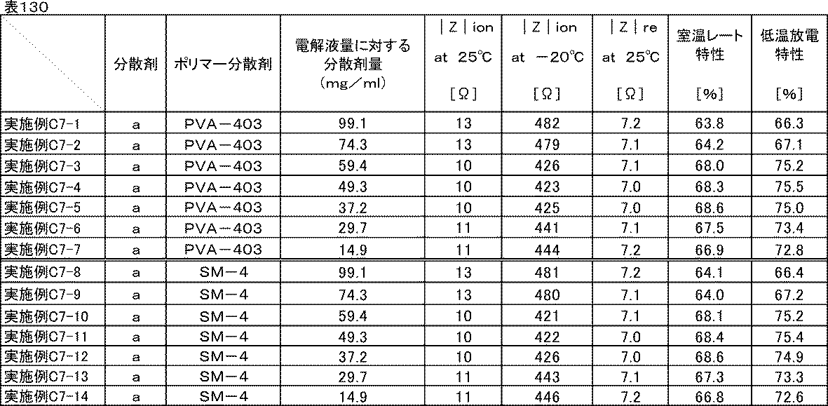
[実施例C8-1]電解液の影響調査
実施例C2-2で用いた電解液(エチレンカーボネートとジエチルカーボネートを体積比1:1に混合した混合溶媒にLiPF6を1Mの濃度で溶解させた非水電解液)の代わりに、エチレンカーボネートとジエチルカーボネートを体積比1:2に混合した混合溶媒に、LiPF6を1Mの濃度で溶解させた非水電解液をそれぞれ用いた以外は、実施例C2-2と同様に正極評価用セルを組み立て、イオン抵抗、反応抵抗、室温レート特性、低温放電特性、サイクル特性の評価を行った。
実施例C2-2で用いた電解液(エチレンカーボネートとジエチルカーボネートを体積比1:1に混合した混合溶媒にLiPF6を1Mの濃度で溶解させた非水電解液)の代わりに、エチレンカーボネートとジエチルカーボネートを体積比1:2に混合した混合溶媒に、LiPF6を1Mの濃度で溶解させた非水電解液をそれぞれ用いた以外は、実施例C2-2と同様に正極評価用セルを組み立て、イオン抵抗、反応抵抗、室温レート特性、低温放電特性、サイクル特性の評価を行った。
[実施例C8-2]
実施例C2-2で用いた電解液(エチレンカーボネートとジエチルカーボネートを体積比1:1に混合した混合溶媒にLiPF6を1Mの濃度で溶解させた非水電解液)の代わりに、エチレンカーボネートとエチルメチルカーボネート、ジメチルカーボネートを体積比1:1:1に混合した混合溶媒に、LiPF6を1Mの濃度で溶解させた非水電解液をそれぞれ用いた以外は、実施例C2-2と同様に正極評価用セルを組み立て、イオン抵抗、反応抵抗、室温レート特性、低温放電特性、サイクル特性の評価を行った。
実施例C2-2で用いた電解液(エチレンカーボネートとジエチルカーボネートを体積比1:1に混合した混合溶媒にLiPF6を1Mの濃度で溶解させた非水電解液)の代わりに、エチレンカーボネートとエチルメチルカーボネート、ジメチルカーボネートを体積比1:1:1に混合した混合溶媒に、LiPF6を1Mの濃度で溶解させた非水電解液をそれぞれ用いた以外は、実施例C2-2と同様に正極評価用セルを組み立て、イオン抵抗、反応抵抗、室温レート特性、低温放電特性、サイクル特性の評価を行った。
[実施例C8-3]電解液の影響調査-2
実施例C2-8で用いた電解液(エチレンカーボネートとジエチルカーボネートを体積比1:1に混合した混合溶媒にLiPF6を1Mの濃度で溶解させた非水電解液)の代わりに、エチレンカーボネートとジエチルカーボネートを体積比1:2に混合した混合溶媒に、LiPF6を1Mの濃度で溶解させた非水電解液をそれぞれ用いた以外は、実施例C2-8と同様に正極評価用セルを組み立て、イオン抵抗、反応抵抗、室温レート特性、低温放電特性、サイクル特性の評価を行った。
実施例C2-8で用いた電解液(エチレンカーボネートとジエチルカーボネートを体積比1:1に混合した混合溶媒にLiPF6を1Mの濃度で溶解させた非水電解液)の代わりに、エチレンカーボネートとジエチルカーボネートを体積比1:2に混合した混合溶媒に、LiPF6を1Mの濃度で溶解させた非水電解液をそれぞれ用いた以外は、実施例C2-8と同様に正極評価用セルを組み立て、イオン抵抗、反応抵抗、室温レート特性、低温放電特性、サイクル特性の評価を行った。
[実施例C8-4]
実施例C2-8で用いた電解液(エチレンカーボネートとジエチルカーボネートを体積比1:1に混合した混合溶媒にLiPF6を1Mの濃度で溶解させた非水電解液)の代わりに、エチレンカーボネートとエチルメチルカーボネート、ジメチルカーボネートを体積比1:1:1に混合した混合溶媒に、LiPF6を1Mの濃度で溶解させた非水電解液をそれぞれ用いた以外は、実施例C2-8と同様に正極評価用セルを組み立て、イオン抵抗、反応抵抗、室温レート特性、低温放電特性、サイクル特性の評価を行った。
実施例C2-8で用いた電解液(エチレンカーボネートとジエチルカーボネートを体積比1:1に混合した混合溶媒にLiPF6を1Mの濃度で溶解させた非水電解液)の代わりに、エチレンカーボネートとエチルメチルカーボネート、ジメチルカーボネートを体積比1:1:1に混合した混合溶媒に、LiPF6を1Mの濃度で溶解させた非水電解液をそれぞれ用いた以外は、実施例C2-8と同様に正極評価用セルを組み立て、イオン抵抗、反応抵抗、室温レート特性、低温放電特性、サイクル特性の評価を行った。
[比較例C8-1]
比較例C2-5で用いた電解液(エチレンカーボネートとジエチルカーボネートを体積比1:1に混合した混合溶媒にLiPF6を1Mの濃度で溶解させた非水電解液)の代わりに、エチレンカーボネートとジエチルカーボネートを体積比1:2に混合した混合溶媒にLiPF6を1Mの濃度で溶解させた非水電解液を用いた以外は、比較例C2-5と同様に正極評価用セルを組み立て、イオン抵抗、反応抵抗、室温レート特性、低温放電特性、サイクル特性の評価を行った。
比較例C2-5で用いた電解液(エチレンカーボネートとジエチルカーボネートを体積比1:1に混合した混合溶媒にLiPF6を1Mの濃度で溶解させた非水電解液)の代わりに、エチレンカーボネートとジエチルカーボネートを体積比1:2に混合した混合溶媒にLiPF6を1Mの濃度で溶解させた非水電解液を用いた以外は、比較例C2-5と同様に正極評価用セルを組み立て、イオン抵抗、反応抵抗、室温レート特性、低温放電特性、サイクル特性の評価を行った。
[比較例C8-2]
比較例C2-5で用いた電解液(エチレンカーボネートとジエチルカーボネートを体積比1:1に混合した混合溶媒にLiPF6を1Mの濃度で溶解させた非水電解液)の代わりに、エチレンカーボネートとエチルメチルカーボネート、ジメチルカーボネートを体積比1:1:1に混合した混合溶媒に、LiPF6を1Mの濃度で溶解させた非水電解液を用いた以外は、比較例C2-5と同様に正極評価用セルを組み立て、イオン抵抗、反応抵抗、室温レート特性、低温放電特性、サイクル特性の評価を行った。
比較例C2-5で用いた電解液(エチレンカーボネートとジエチルカーボネートを体積比1:1に混合した混合溶媒にLiPF6を1Mの濃度で溶解させた非水電解液)の代わりに、エチレンカーボネートとエチルメチルカーボネート、ジメチルカーボネートを体積比1:1:1に混合した混合溶媒に、LiPF6を1Mの濃度で溶解させた非水電解液を用いた以外は、比較例C2-5と同様に正極評価用セルを組み立て、イオン抵抗、反応抵抗、室温レート特性、低温放電特性、サイクル特性の評価を行った。
<評価結果>
実施例C2-2、C2-8、C8-1~C8-4、比較例C2-5、C8-1、C8-2のイオン抵抗、反応抵抗、室温レート特性、低温放電特性、サイクル特性の評価結果を表131に示す。
実施例C2-2、C2-8、C8-1~C8-4、比較例C2-5、C8-1、C8-2のイオン抵抗、反応抵抗、室温レート特性、低温放電特性、サイクル特性の評価結果を表131に示す。

実施例C8-1~C8-4より、電解液の種類によらず、すべての特性が比較例よりも良化することが確認できた。本実施例に示した電解液以外でも、一般的に用いられる非水電解液であれば、種類によらず同じ効果が得られると思われる。
次に、活物質の種類を変更して同様に評価した。
[実施例C9-1~C9-3]活物質種の比較
実施例C1-2で用いた炭素材料分散ワニスを用いて、表132に示した活物質と組成に従って、実施例C2-2と同様にして炭素材料分散液、炭素材料分散ワニス、正極合剤ペースト、電極をそれぞれ作製し、剥離強度試験を行った。またその電極を、実施例C2-2において実施例C1-2で作製した電極を用いた代わりにそれぞれ使用し、実施例C2-2と同様の方法でリチウムイオン二次電池正極評価用のセルを組み立て、イオン抵抗、反応抵抗、室温レート特性、低温放電特性、サイクル特性の評価を行った。
実施例C1-2で用いた炭素材料分散ワニスを用いて、表132に示した活物質と組成に従って、実施例C2-2と同様にして炭素材料分散液、炭素材料分散ワニス、正極合剤ペースト、電極をそれぞれ作製し、剥離強度試験を行った。またその電極を、実施例C2-2において実施例C1-2で作製した電極を用いた代わりにそれぞれ使用し、実施例C2-2と同様の方法でリチウムイオン二次電池正極評価用のセルを組み立て、イオン抵抗、反応抵抗、室温レート特性、低温放電特性、サイクル特性の評価を行った。
[実施例C9-4~C9-6]活物質種の比較-2
実施例C1-8で用いた炭素材料分散ワニスを用いて、表132に示した活物質と組成に従って、実施例C2-8と同様にして炭素材料分散液、炭素材料分散ワニス、正極合剤ペースト、電極をそれぞれ作製し、剥離強度試験を行った。またその電極を、実施例C2-8において実施例C1-8で作製した電極を用いた代わりにそれぞれ使用し、実施例C2-8と同様の方法でリチウムイオン二次電池正極評価用のセルを組み立て、イオン抵抗、反応抵抗、室温レート特性、低温放電特性、サイクル特性の評価を行った。
実施例C1-8で用いた炭素材料分散ワニスを用いて、表132に示した活物質と組成に従って、実施例C2-8と同様にして炭素材料分散液、炭素材料分散ワニス、正極合剤ペースト、電極をそれぞれ作製し、剥離強度試験を行った。またその電極を、実施例C2-8において実施例C1-8で作製した電極を用いた代わりにそれぞれ使用し、実施例C2-8と同様の方法でリチウムイオン二次電池正極評価用のセルを組み立て、イオン抵抗、反応抵抗、室温レート特性、低温放電特性、サイクル特性の評価を行った。
[比較例C9-1~9-3]
比較例C1-2で用いた炭素材料分散ワニスを用いて、表132に示した活物質と組成に従って、比較例C2-1と同様にして炭素材料分散液、炭素材料分散ワニス、正極合剤ペースト、電極をそれぞれ作製し、剥離強度試験を行った。またその電極を、比較例C2-1において比較例C1-2で作製した電極を用いた代わりにそれぞれ使用し、比較例C2-1と同様の方法でリチウムイオン二次電池正極評価用のセルを組み立て、イオン抵抗、反応抵抗、室温レート特性、低温放電特性、サイクル特性の評価を行った。
比較例C1-2で用いた炭素材料分散ワニスを用いて、表132に示した活物質と組成に従って、比較例C2-1と同様にして炭素材料分散液、炭素材料分散ワニス、正極合剤ペースト、電極をそれぞれ作製し、剥離強度試験を行った。またその電極を、比較例C2-1において比較例C1-2で作製した電極を用いた代わりにそれぞれ使用し、比較例C2-1と同様の方法でリチウムイオン二次電池正極評価用のセルを組み立て、イオン抵抗、反応抵抗、室温レート特性、低温放電特性、サイクル特性の評価を行った。
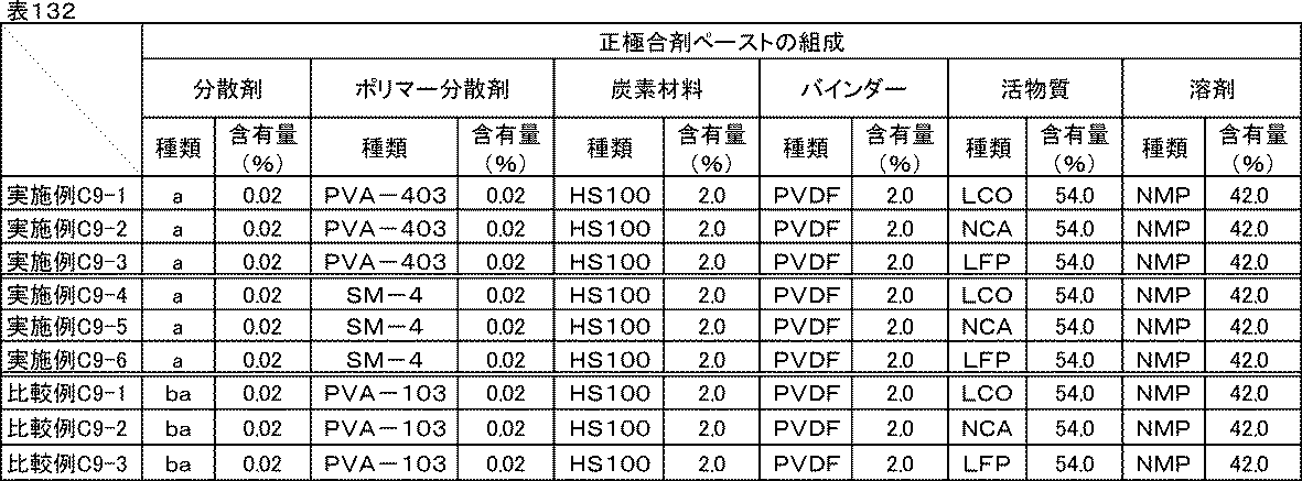
<評価結果>
実施例C9-1~C9-6、比較例C9-1~C9-3のイオン抵抗、反応抵抗、室温レート特性、低温放電特性、剥離強度試験、サイクル特性の評価結果を表133に示す。
実施例C9-1~C9-6、比較例C9-1~C9-3のイオン抵抗、反応抵抗、室温レート特性、低温放電特性、剥離強度試験、サイクル特性の評価結果を表133に示す。
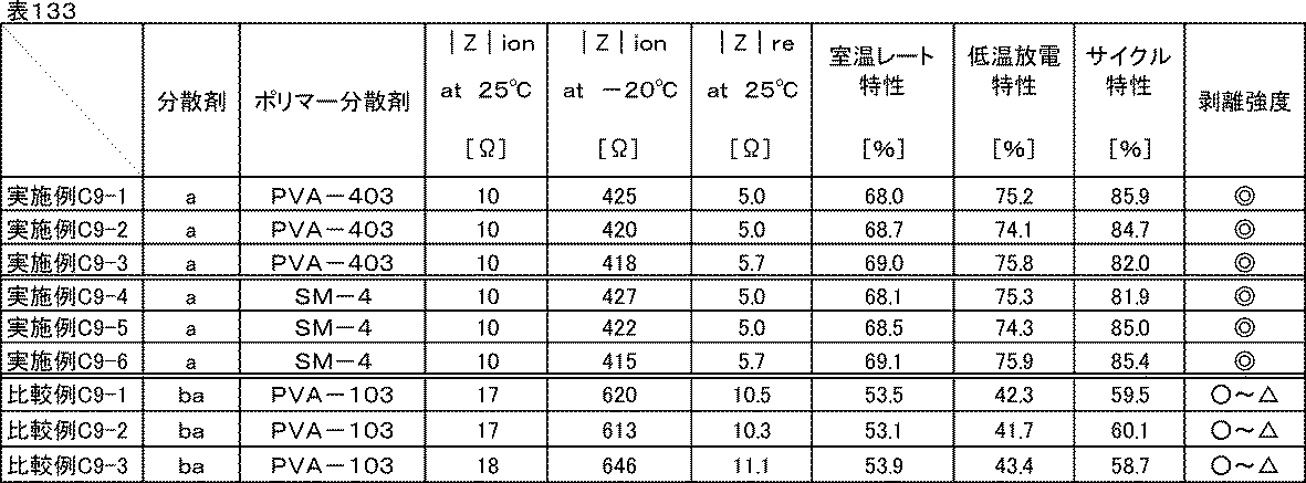
活物質の性能によって差異はあるものの、同じ活物質で実施例と比較例を比較すると、実施例C9-1~C9-6はいずれも電池特性、剥離強度、サイクル特性が向上していることが確認できた。
続いて、本発明の電池用組成物を負極に用いた場合の評価を行った。
[実施例C10-1]
<炭素材料分散ワニスの調製>
表134に示す組成に従い、実施例C1-1で作製した分散剤aとポリマー分散剤PVA-103を含む炭素材料分散液とバインダー、N-メチル-2-ピロリドンをディスパーにて混合し、炭素材料分散ワニスを得た。
<炭素材料分散ワニスの調製>
表134に示す組成に従い、実施例C1-1で作製した分散剤aとポリマー分散剤PVA-103を含む炭素材料分散液とバインダー、N-メチル-2-ピロリドンをディスパーにて混合し、炭素材料分散ワニスを得た。
<負極合剤ペーストの調製>
表134に示す組成に従い、調製した分散剤aとポリマー分散剤PVA-103を含む炭素材料分散ワニスと活物質、N-メチル-2-ピロリドンをディスパーにて混合し、負極合剤ペーストを得た。
表134に示す組成に従い、調製した分散剤aとポリマー分散剤PVA-103を含む炭素材料分散ワニスと活物質、N-メチル-2-ピロリドンをディスパーにて混合し、負極合剤ペーストを得た。

<電極の作製>
調製した分散剤aとポリマー分散剤PVA-103を含む負極合剤ペーストを、厚さ20μmの銅箔上にドクターブレードを用いて塗工した後、減圧下120℃で30分間乾燥し、ローラープレス機にて圧延処理し、塗布量15mg/cm2、密度1.8g/cm3の電極を作製した。厚みや密度が均一な電極が得られた。
調製した分散剤aとポリマー分散剤PVA-103を含む負極合剤ペーストを、厚さ20μmの銅箔上にドクターブレードを用いて塗工した後、減圧下120℃で30分間乾燥し、ローラープレス機にて圧延処理し、塗布量15mg/cm2、密度1.8g/cm3の電極を作製した。厚みや密度が均一な電極が得られた。
[実施例C10-2~10-10]
実施例C10-1で用いたPVA-103を表135に示したポリマー分散剤に置き換えた以外は、実施例C10-1と同様にして炭素材料分散液、炭素材料分散ワニス、負極合剤ペースト、電極を作製した。
実施例C10-1で用いたPVA-103を表135に示したポリマー分散剤に置き換えた以外は、実施例C10-1と同様にして炭素材料分散液、炭素材料分散ワニス、負極合剤ペースト、電極を作製した。
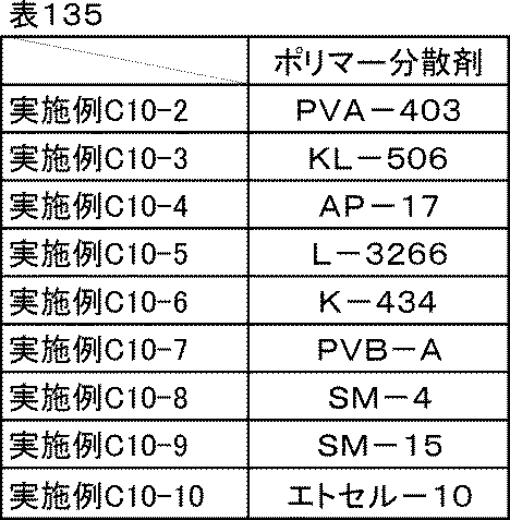
[実施例C10-1a]分散剤aのみ
表136に示す通り、実施例C10-1で用いたポリマー分散剤PVA-103を分散剤aに置き換えて分散剤を分散剤aのみとした以外は、実施例C10-1と同様にして炭素材料分散液、炭素材料分散ワニス、負極合剤ペースト、電極を作製した。
表136に示す通り、実施例C10-1で用いたポリマー分散剤PVA-103を分散剤aに置き換えて分散剤を分散剤aのみとした以外は、実施例C10-1と同様にして炭素材料分散液、炭素材料分散ワニス、負極合剤ペースト、電極を作製した。
[比較例C10-1]分散剤種の比較-1
表136に示す通り、参考例C10-1で用いた分散剤aを分散剤baに置き換えた以外は、実施例C10-1aと同様にして炭素材料分散液、炭素材料分散ワニス、負極合剤ペースト、電極を作製した。
表136に示す通り、参考例C10-1で用いた分散剤aを分散剤baに置き換えた以外は、実施例C10-1aと同様にして炭素材料分散液、炭素材料分散ワニス、負極合剤ペースト、電極を作製した。
[比較例C10-2]分散剤種の比較-2
表136に示す通り、実施例C10-1で用いた分散剤aを分散剤baに置き換えた以外は、実施例C10-1aと同様にして炭素材料分散液、炭素材料分散ワニス、負極合剤ペースト、電極を作製した。
表136に示す通り、実施例C10-1で用いた分散剤aを分散剤baに置き換えた以外は、実施例C10-1aと同様にして炭素材料分散液、炭素材料分散ワニス、負極合剤ペースト、電極を作製した。
[比較例C10-3、C10-4]分散剤種の比較-3
比較例C10-2で用いたPVA-103の代わりに、表136に示したポリマー分散剤をそれぞれ使用した以外は、比較例C10-2と同様にして炭素材料分散液、炭素材料分散ワニス、負極合剤ペースト、電極を作製した。
比較例C10-2で用いたPVA-103の代わりに、表136に示したポリマー分散剤をそれぞれ使用した以外は、比較例C10-2と同様にして炭素材料分散液、炭素材料分散ワニス、負極合剤ペースト、電極を作製した。
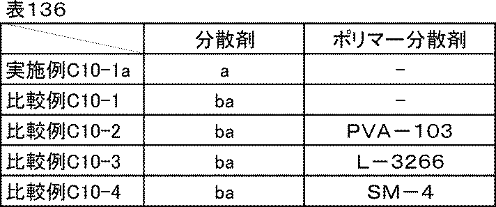
<評価結果>
実施例C10-1~C10-10、実施例C10-1a、比較例C10-1~C10-4で調製した炭素材料分散液、炭素材料分散ワニス、負極合剤ペーストは、いずれも良好な分散状態であり、1か月経時後も沈降や増粘はなかった。
実施例C10-1~C10-10、実施例C10-1a、比較例C10-1~C10-4で調製した炭素材料分散液、炭素材料分散ワニス、負極合剤ペーストは、いずれも良好な分散状態であり、1か月経時後も沈降や増粘はなかった。
実施例C10-1~C10-10、実施例C10-1a、比較例C10-1~C10-4で作製した電極の剥離強度試験を行った。その結果を表137に示す。剥離強度試験の結果は、参考例C10-1を100%としたとき、◎:200%以上、◎~○:200%未満175%以上、○:175%未満150%以上、○~△:150%未満120%以上、△:120%未満80%以上、とした。以下、負極合材においての剥離強度試験の結果は、これに従うものとする。分散剤baのみを用いた比較例C10-1と比較して、各種ポリマー分散剤を併用した比較例C10-1~C10-4は剥離強度がいずれも若干向上した。これは、膜形成能がない低分子の分散剤baの代わりに膜形成に関与できるポリマー成分が入ったことによって若干ではあるが向上したものによると考えられる。
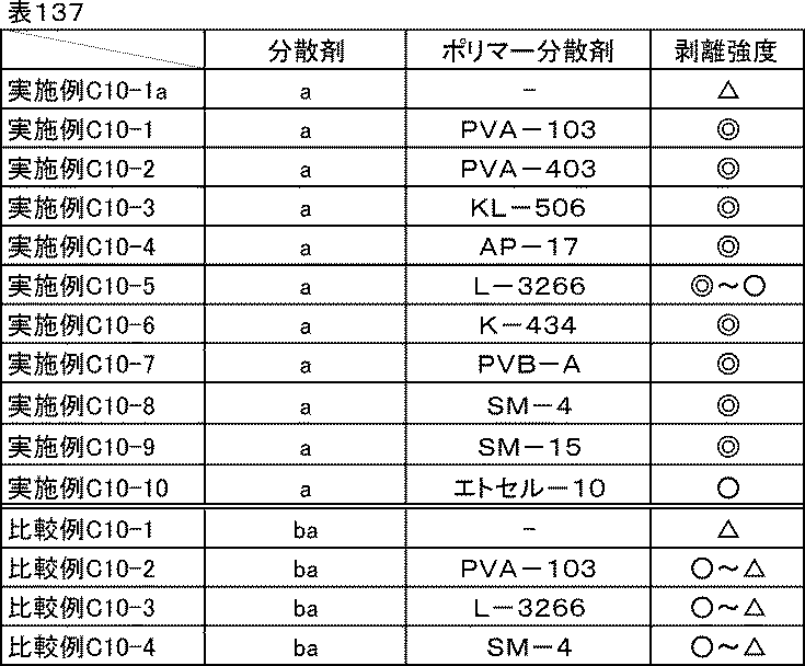
[実施例C10-11~C10-188]
剥離強度向上効果が、一般式(1)で示される他のトリアジン誘導体でも得られるか確認するために、同様に試験を行った。実施例C10-1で使用した分散剤、ポリマー分散剤を表138に示した分散剤、ポリマー分散剤にそれぞれ置き換えた以外は、実施例C10-1と同様にして炭素材料分散液、炭素材料分散ワニス、負極合剤ペースト、電極を作製し、剥離強度試験を行った。
剥離強度向上効果が、一般式(1)で示される他のトリアジン誘導体でも得られるか確認するために、同様に試験を行った。実施例C10-1で使用した分散剤、ポリマー分散剤を表138に示した分散剤、ポリマー分散剤にそれぞれ置き換えた以外は、実施例C10-1と同様にして炭素材料分散液、炭素材料分散ワニス、負極合剤ペースト、電極を作製し、剥離強度試験を行った。

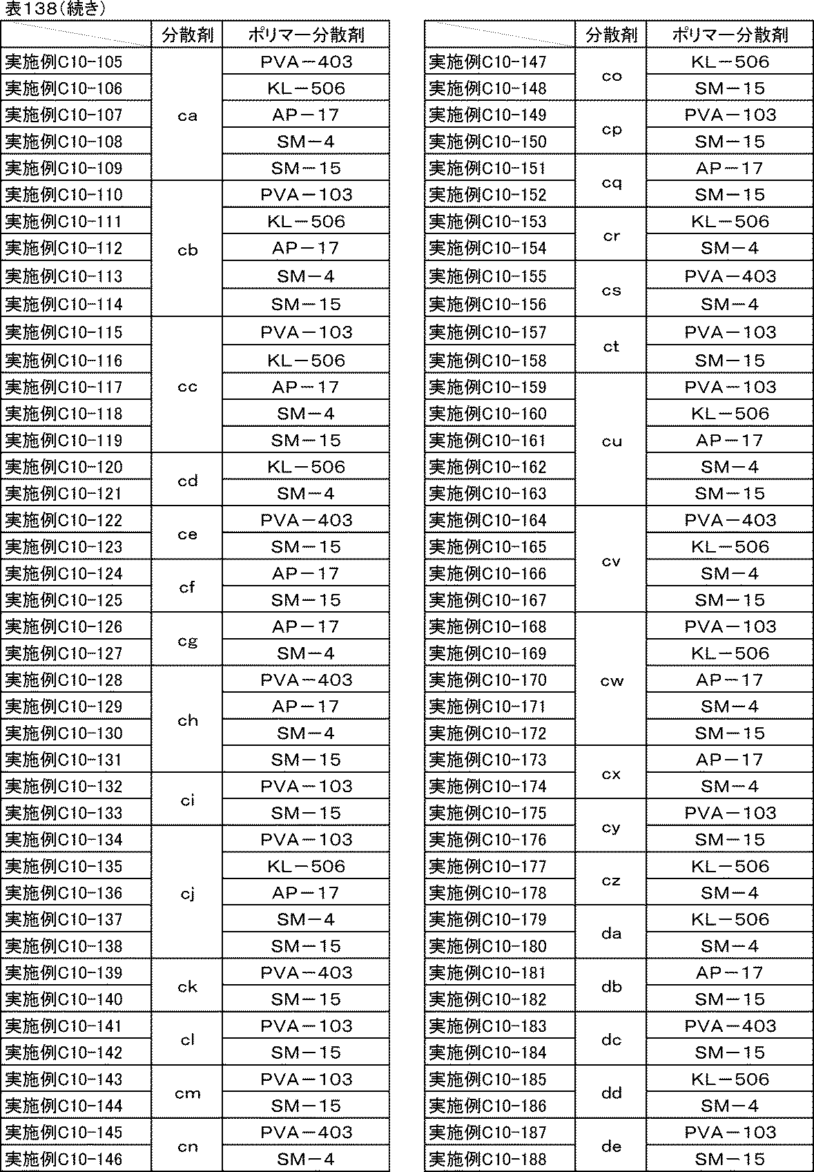
[参考例C10-189]トリアジン誘導体とポリマー分散剤の併用
表139に示す通り、実施例C10-1で用いた分散剤aをトリアジン誘導体Aに置き換えた以外は、実施例C10-1と同様にして炭素材料分散液、炭素材料分散ワニス、負極合剤ペースト、電極を作製し、剥離強度試験を行った。
表139に示す通り、実施例C10-1で用いた分散剤aをトリアジン誘導体Aに置き換えた以外は、実施例C10-1と同様にして炭素材料分散液、炭素材料分散ワニス、負極合剤ペースト、電極を作製し、剥離強度試験を行った。
[参考例C10-190~C10-193]トリアジン誘導体とポリマー分散剤の併用-2
参考例C10-189で用いたPVA-103の代わりに、表139に示したポリマー分散剤をそれぞれ使用し、トリアジン誘導体Aの代わりに表139に示したトリアジン誘導体をそれぞれ用いた以外は、参考例C10-189と同様にして炭素材料分散液、炭素材料分散ワニス、負極合剤ペースト、電極を作製し、剥離強度試験を行った。
参考例C10-189で用いたPVA-103の代わりに、表139に示したポリマー分散剤をそれぞれ使用し、トリアジン誘導体Aの代わりに表139に示したトリアジン誘導体をそれぞれ用いた以外は、参考例C10-189と同様にして炭素材料分散液、炭素材料分散ワニス、負極合剤ペースト、電極を作製し、剥離強度試験を行った。
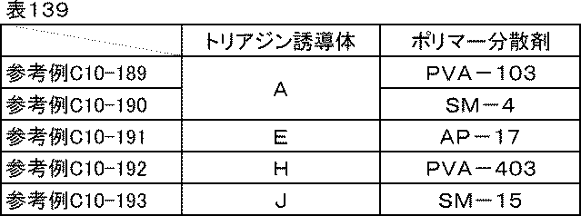
[実施例C10-194]ポリマー分散剤の併用
表140に示す通り、実施例C10-1で用いたPVA-103のさらに半量をSM-15に置き換えた以外は、実施例C10-1と同様にして炭素材料分散液、炭素材料分散ワニス、負極合剤ペースト、電極を作製し、剥離強度試験を行った。
表140に示す通り、実施例C10-1で用いたPVA-103のさらに半量をSM-15に置き換えた以外は、実施例C10-1と同様にして炭素材料分散液、炭素材料分散ワニス、負極合剤ペースト、電極を作製し、剥離強度試験を行った。
[実施例C10-195、C10-196]ポリマー分散剤の併用-2
実施例C10-194で用いたPVA-103の代わりに、表140に示したポリマー分散剤をそれぞれ使用した以外は、実施例C10-194と同様にして炭素材料分散液、炭素材料分散ワニス、負極合剤ペースト、電極を作製し、剥離強度試験を行った。
実施例C10-194で用いたPVA-103の代わりに、表140に示したポリマー分散剤をそれぞれ使用した以外は、実施例C10-194と同様にして炭素材料分散液、炭素材料分散ワニス、負極合剤ペースト、電極を作製し、剥離強度試験を行った。
[参考例C10-197~C10-199]ポリマー分散剤の併用-3
実施例C10-194で用いたPVA-103の代わりに、表140に示したポリマー分散剤をそれぞれ使用し、分散剤aの代わりにトリアジン誘導体Aを用いた以外は、実施例C10-194と同様にして炭素材料分散液、炭素材料分散ワニス、負極合剤ペースト、電極を作製し、剥離強度試験を行った。
実施例C10-194で用いたPVA-103の代わりに、表140に示したポリマー分散剤をそれぞれ使用し、分散剤aの代わりにトリアジン誘導体Aを用いた以外は、実施例C10-194と同様にして炭素材料分散液、炭素材料分散ワニス、負極合剤ペースト、電極を作製し、剥離強度試験を行った。

[比較例C10-5~C10-7]
実施例C10-1aで用いた分散剤aを表141で示した分散剤に置き換えた以外は、実施例C10-1aと同様にして炭素材料分散液、炭素材料分散ワニス、負極合剤ペースト、電極を作製し、剥離強度試験を行った。
実施例C10-1aで用いた分散剤aを表141で示した分散剤に置き換えた以外は、実施例C10-1aと同様にして炭素材料分散液、炭素材料分散ワニス、負極合剤ペースト、電極を作製し、剥離強度試験を行った。

[比較例C10-8~C10-13]
実施例C10-1で使用した分散剤a、ポリマー分散剤PVA-103を表142に示した分散剤、ポリマー分散剤にそれぞれ置き換えた以外は、実施例C10-1と同様にして炭素材料分散液、炭素材料分散ワニス、負極合剤ペースト、電極を作製し、剥離強度試験を行った。
実施例C10-1で使用した分散剤a、ポリマー分散剤PVA-103を表142に示した分散剤、ポリマー分散剤にそれぞれ置き換えた以外は、実施例C10-1と同様にして炭素材料分散液、炭素材料分散ワニス、負極合剤ペースト、電極を作製し、剥離強度試験を行った。
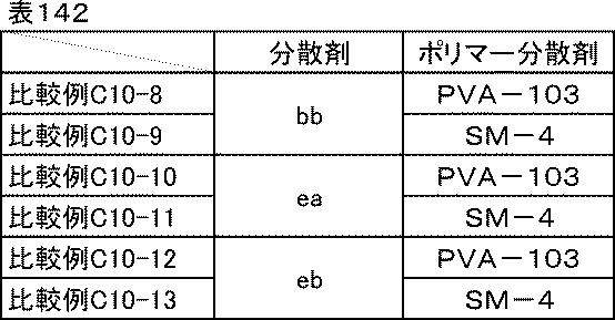
<評価結果>
実施例C10-11~C10-188、参考例C10-189~C10-193、実施例C10-194~C10-196、参考例C10-197~C10-199、実施例C10-1a、比較例C10-5~C10-13で作製した電極の剥離強度試験結果を表143に示す。分散剤baの場合と同様に、分散剤bb、ea、ebと各種ポリマー分散剤を併用しても若干の剥離強度向上しかしなかったが、分散剤b~aj、ca~de、トリアジン誘導体A、E、H、Jの場合は、分散剤aと同様に、各種ポリマー分散剤1種または2種を併用することで大幅な剥離強度の向上が確認できた。
実施例C10-11~C10-188、参考例C10-189~C10-193、実施例C10-194~C10-196、参考例C10-197~C10-199、実施例C10-1a、比較例C10-5~C10-13で作製した電極の剥離強度試験結果を表143に示す。分散剤baの場合と同様に、分散剤bb、ea、ebと各種ポリマー分散剤を併用しても若干の剥離強度向上しかしなかったが、分散剤b~aj、ca~de、トリアジン誘導体A、E、H、Jの場合は、分散剤aと同様に、各種ポリマー分散剤1種または2種を併用することで大幅な剥離強度の向上が確認できた。
この効果は一般式(1)で示されるトリアジン誘導体に特有であることから、酸性官能基を有するアリーレン基と、フェノール性水酸基2つがひとつのトリアジン環に直結している構造によって、ポリマー分散剤との間に水素結合などの強い分子間力が作用したことによると考えられる。

続いてリチウムイオン二次電池負極評価用のセルを組み立て、イオン抵抗、反応抵抗、室温レート特性、低温放電特性、サイクル特性の評価を行った。
[実施例C11-1]
<リチウムイオン二次電池負極評価用セルの組み立て>
実施例C10-1で作製した分散剤a含む電極を直径18mmに打ち抜き負極とし、金属リチウム箔(厚さ0.15mm)を正極として、負極および正極の間に多孔質ポリプロピレンフィルムからなるセパレーター(厚さ20μm、空孔率50%)を挿入積層し、電解液(エチレンカーボネートとジエチルカーボネートを体積比1:1に混合した混合溶媒にLiPF6を1Mの濃度で溶解させた非水電解液)を0.1ml満たして二極密閉式金属セル(宝泉社製HSフラットセル)を組み立てた。セルの組み立てはアルゴンガス置換したグローブボックス内で行った。
<リチウムイオン二次電池負極評価用セルの組み立て>
実施例C10-1で作製した分散剤a含む電極を直径18mmに打ち抜き負極とし、金属リチウム箔(厚さ0.15mm)を正極として、負極および正極の間に多孔質ポリプロピレンフィルムからなるセパレーター(厚さ20μm、空孔率50%)を挿入積層し、電解液(エチレンカーボネートとジエチルカーボネートを体積比1:1に混合した混合溶媒にLiPF6を1Mの濃度で溶解させた非水電解液)を0.1ml満たして二極密閉式金属セル(宝泉社製HSフラットセル)を組み立てた。セルの組み立てはアルゴンガス置換したグローブボックス内で行った。
<イオン抵抗評価>
実施例C2-1と同じ条件でインピーダンス測定を行い、-20℃および室温(25℃)におけるイオン抵抗|Z|ionを求めた。
実施例C2-1と同じ条件でインピーダンス測定を行い、-20℃および室温(25℃)におけるイオン抵抗|Z|ionを求めた。
<反応抵抗評価>
イオン抵抗評価に続いて、充放電測定装置を用い、室温にて0.1Cの定電流定電圧充電(下限電圧0.0V)で満充電とし、0.1Cの定電流で放電上限電圧2.0Vまで放電を行う充放電を1サイクルとして合計5サイクル行った。5サイクル目の0.1C放電容量を記録しておいた。次に、2.0Vまで放電した状態の負極評価用セルをインピーダンスアナライザーに接続し、2.0V、振幅10mV、周波数0.1Hzから1MHzにおいて交流インピーダンス測定を行った。結果をコールコールプロット法にて複素平面上にプロットすると、半円状の曲線が得られる。この円弧の直径を活物質の反応抵抗|Z|reとした。
イオン抵抗評価に続いて、充放電測定装置を用い、室温にて0.1Cの定電流定電圧充電(下限電圧0.0V)で満充電とし、0.1Cの定電流で放電上限電圧2.0Vまで放電を行う充放電を1サイクルとして合計5サイクル行った。5サイクル目の0.1C放電容量を記録しておいた。次に、2.0Vまで放電した状態の負極評価用セルをインピーダンスアナライザーに接続し、2.0V、振幅10mV、周波数0.1Hzから1MHzにおいて交流インピーダンス測定を行った。結果をコールコールプロット法にて複素平面上にプロットすると、半円状の曲線が得られる。この円弧の直径を活物質の反応抵抗|Z|reとした。
<室温レート特性・低温放電特性評価>
次に、室温にて0.1Cで同様に満充電にした後、0.5Cの定電流で放電上限電圧2.0Vまで放電し、再度0.1Cで満充電にしてから5Cの定電流で2.0Vまで放電した。反応抵抗評価の試験で記録しておいた5サイクル目の0.1C放電容量に対する5Cの放電容量の比率を、室温レート特性(%)とした。またここで、室温における0.5C放電容量を記録しておいた。続いて、室温、0.1Cで同様に満充電にしてから-20℃の恒温槽内に移して12時間静置し、0.5Cの定電流で同じく放電した。室温の0.5C放電容量に対する-20℃の0.5C放電容量の比率を、低温放電特性(%)とした。
次に、室温にて0.1Cで同様に満充電にした後、0.5Cの定電流で放電上限電圧2.0Vまで放電し、再度0.1Cで満充電にしてから5Cの定電流で2.0Vまで放電した。反応抵抗評価の試験で記録しておいた5サイクル目の0.1C放電容量に対する5Cの放電容量の比率を、室温レート特性(%)とした。またここで、室温における0.5C放電容量を記録しておいた。続いて、室温、0.1Cで同様に満充電にしてから-20℃の恒温槽内に移して12時間静置し、0.5Cの定電流で同じく放電した。室温の0.5C放電容量に対する-20℃の0.5C放電容量の比率を、低温放電特性(%)とした。
<サイクル特性評価>
次に、室温で12時間放置し、1Cの定電流定電圧充電(下限電圧0.0V)で満充電とし、1Cの定電流で2.0Vまで放電した。これを1サイクルとして500サイクル繰り返し、1サイクル目の放電容量に対する500サイクル目の放電容量の比率をサイクル特性(%)とした。サイクル特性評価は100%に近いほど良好である。
次に、室温で12時間放置し、1Cの定電流定電圧充電(下限電圧0.0V)で満充電とし、1Cの定電流で2.0Vまで放電した。これを1サイクルとして500サイクル繰り返し、1サイクル目の放電容量に対する500サイクル目の放電容量の比率をサイクル特性(%)とした。サイクル特性評価は100%に近いほど良好である。
[実施例C11-2~C11-188、参考例C11-189~C11-193、実施例C11-194~C11-196、参考例C11-197~C11-199]
実施例C11-1において、実施例C10-1で作製した電極を用いた代わりに、表144に示した電極をそれぞれ用いた以外は、実施例C11-1と同様の方法でリチウムイオン二次電池負極評価用のセルを組み立て、イオン抵抗、反応抵抗、室温レート特性、低温放電特性、サイクル特性の評価を行った。
実施例C11-1において、実施例C10-1で作製した電極を用いた代わりに、表144に示した電極をそれぞれ用いた以外は、実施例C11-1と同様の方法でリチウムイオン二次電池負極評価用のセルを組み立て、イオン抵抗、反応抵抗、室温レート特性、低温放電特性、サイクル特性の評価を行った。
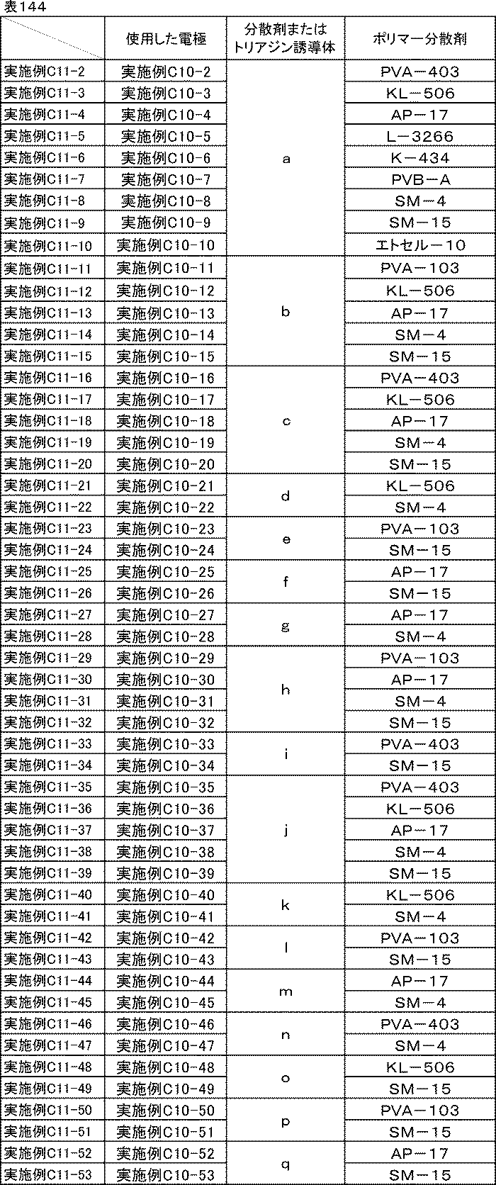

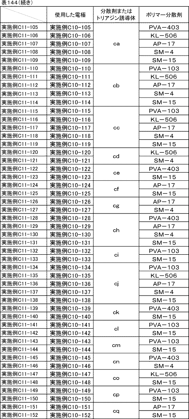
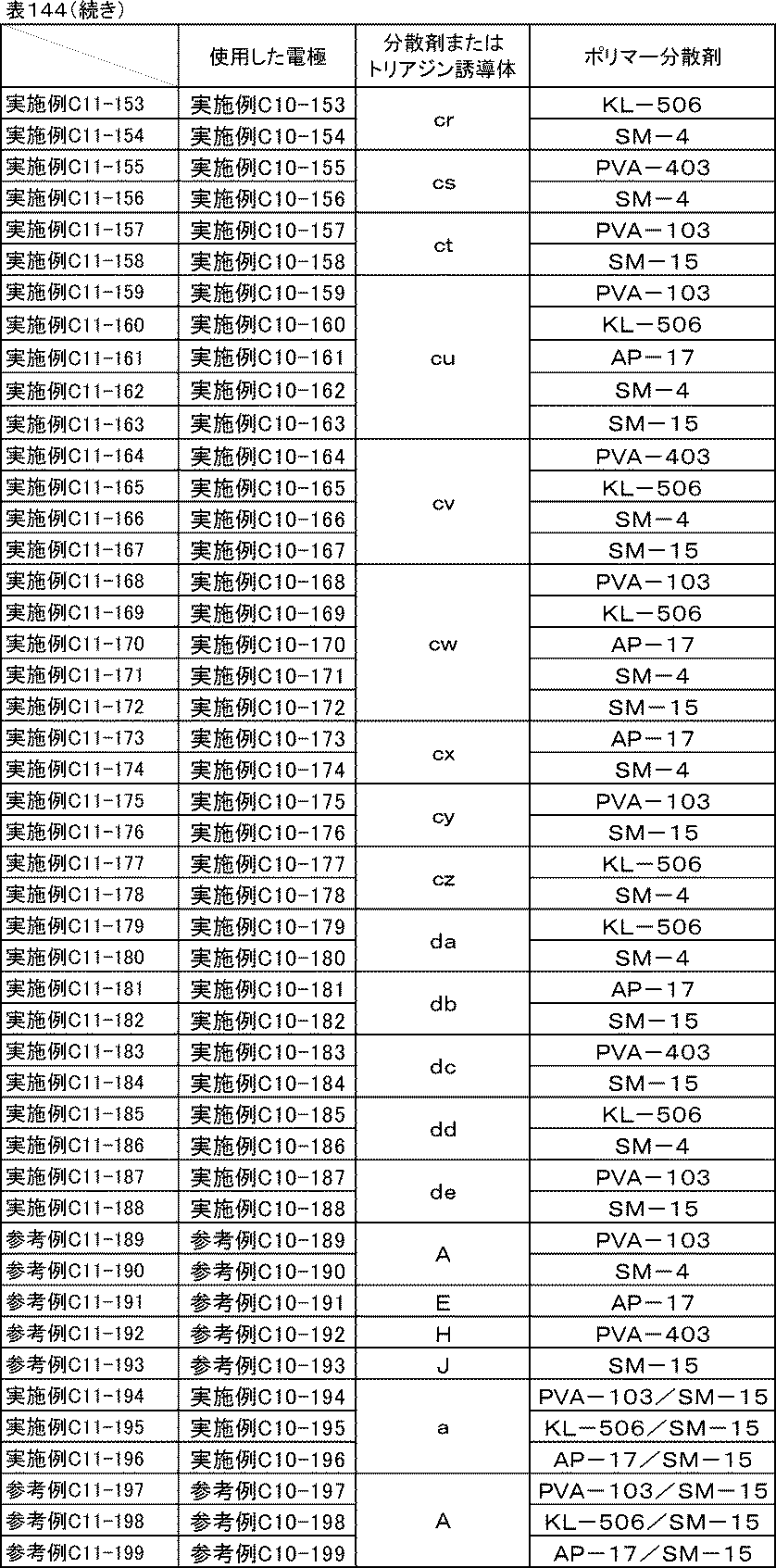
[比較例C11-1~11-4][実施例C11-1a]
実施例C11-1において、実施例C10-1で作製した電極を用いた代わりに、表145に示した電極をそれぞれ用いた以外は、実施例C11-1と同様の方法でリチウムイオン二次電池負極評価用のセルを組み立て、イオン抵抗、反応抵抗、室温レート特性、低温放電特性、サイクル特性の評価を行った。
実施例C11-1において、実施例C10-1で作製した電極を用いた代わりに、表145に示した電極をそれぞれ用いた以外は、実施例C11-1と同様の方法でリチウムイオン二次電池負極評価用のセルを組み立て、イオン抵抗、反応抵抗、室温レート特性、低温放電特性、サイクル特性の評価を行った。
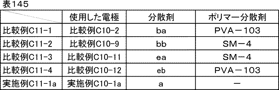
[比較例C11-5]
実施例C10-1で使用した分散剤a、ポリマー分散剤PVA-103を溶剤に置き換えた以外は、実施例C10-1と同様にして炭素材料分散液、炭素材料分散ワニス、負極合剤ペースト、電極を作製した。その電極を、実施例C10-1で作製した電極の代わりに使用し、実施例C11-1と同様の方法でリチウムイオン二次電池負極評価用のセルを組み立て、イオン抵抗、反応抵抗、室温レート特性、低温放電特性、サイクル特性の評価を行った。
実施例C10-1で使用した分散剤a、ポリマー分散剤PVA-103を溶剤に置き換えた以外は、実施例C10-1と同様にして炭素材料分散液、炭素材料分散ワニス、負極合剤ペースト、電極を作製した。その電極を、実施例C10-1で作製した電極の代わりに使用し、実施例C11-1と同様の方法でリチウムイオン二次電池負極評価用のセルを組み立て、イオン抵抗、反応抵抗、室温レート特性、低温放電特性、サイクル特性の評価を行った。
<評価結果>
実施例C11-1~C11-104のイオン抵抗、反応抵抗、室温レート特性、低温放電特性、サイクル特性の評価結果を表146に、実施例C11-105~C11-188、参考例C11-189~C11-193、実施例C11-194~C11-196、参考例C11-197~C11-199のイオン抵抗、反応抵抗、室温レート特性、低温放電特性、サイクル特性の評価結果を表147に、比較例C11-1~C11-5、実施例C11-1aのイオン抵抗、反応抵抗、室温レート特性、低温放電特性、サイクル特性の結果を表148に示す。
実施例C11-1~C11-104のイオン抵抗、反応抵抗、室温レート特性、低温放電特性、サイクル特性の評価結果を表146に、実施例C11-105~C11-188、参考例C11-189~C11-193、実施例C11-194~C11-196、参考例C11-197~C11-199のイオン抵抗、反応抵抗、室温レート特性、低温放電特性、サイクル特性の評価結果を表147に、比較例C11-1~C11-5、実施例C11-1aのイオン抵抗、反応抵抗、室温レート特性、低温放電特性、サイクル特性の結果を表148に示す。
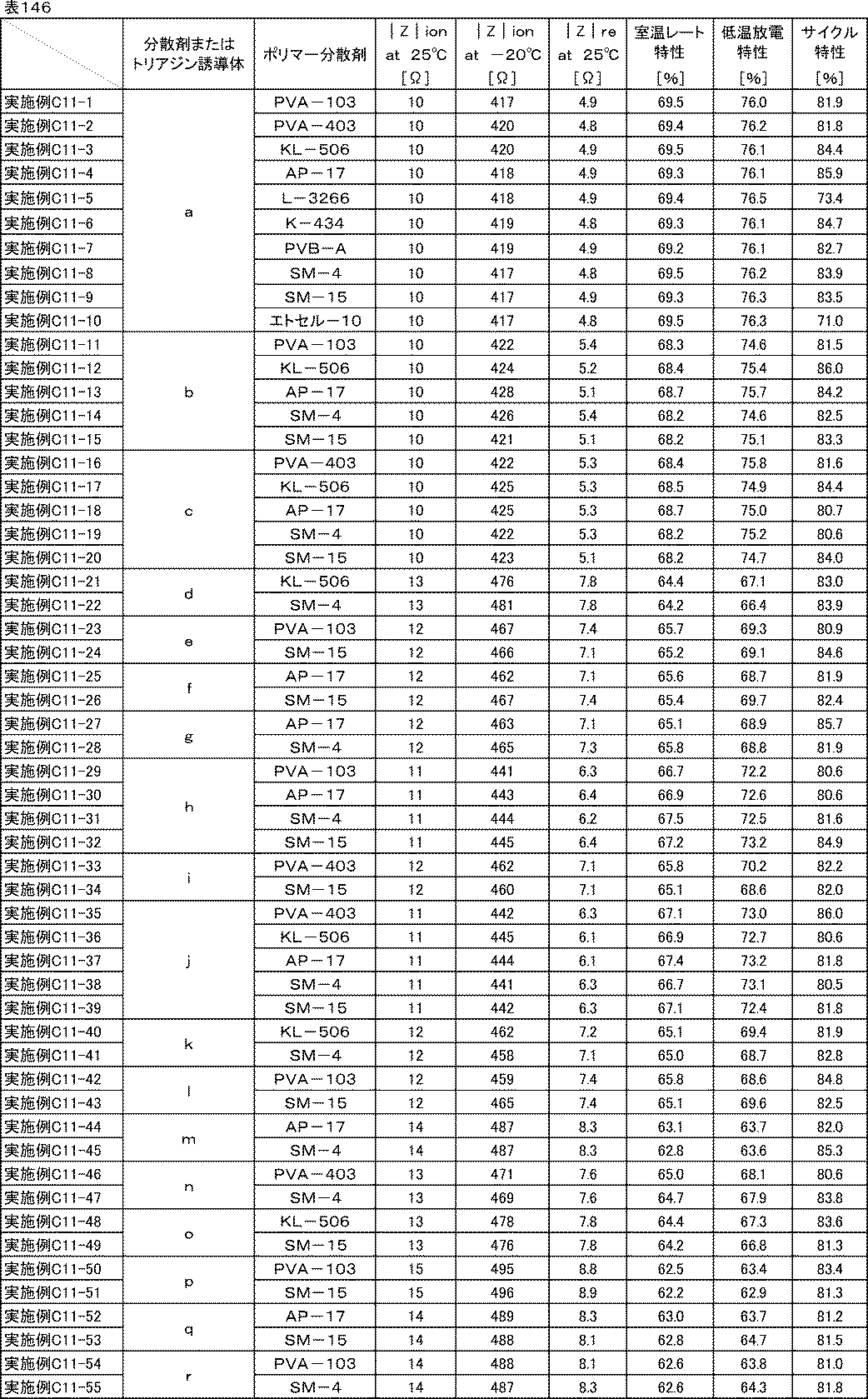
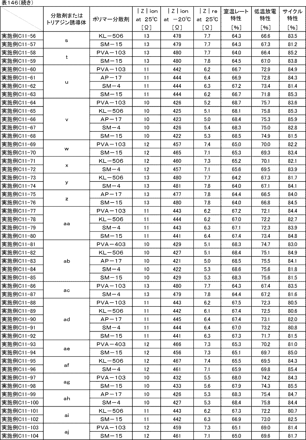


表146、表147、表148からわかる通り、分散剤a~aj、ca~de、トリアジン誘導体A、E、H、Jを用いた実施例C11-1~C11-188、参考例C11-189~C11-193、実施例C11-194~C11-196、参考例C11-197~C11-199、参考例C11-1の負極は室温および-20℃のイオン抵抗、反応抵抗、室温レート特性、低温放電特性の全てにおいて、分散剤ba、bb、ea、ebとポリマー分散剤を用いた比較例C11-1~C11-4や分散剤を用いない比較例C11-5の負極と比べて非常に優れていた。
また、分散剤a~aj、ca~deとポリマー分散剤を用いた実施例C11-1~C11-188、参考例C11-189~C11-193、実施例C11-194~C11-196、参考例C11-197~C11-199の負極は、分散剤ba、bb、ea、ebとポリマー分散剤を用いた比較例C11-1~C11-4や分散剤を用いない比較例C11-5の負極と比べてサイクル特性が大幅に向上した。
このことから本発明の電池用組成物を負極に用いた場合も、正極の場合と同じ効果が得られることが確認できた。
[実施例C12-1]
<炭素材料分散液の調製>
表149に示す組成に従い、ガラス瓶に水と分散剤caとポリマー分散剤PVA-103を仕込み、混合した後、炭素材料を加え、ジルコニアビーズをメディアとして、ペイントコンディショナーで2時間分散し、炭素材料分散液を得た。
<炭素材料分散液の調製>
表149に示す組成に従い、ガラス瓶に水と分散剤caとポリマー分散剤PVA-103を仕込み、混合した後、炭素材料を加え、ジルコニアビーズをメディアとして、ペイントコンディショナーで2時間分散し、炭素材料分散液を得た。
<炭素材料分散ワニスの調製>
表149に示す組成に従い、調製した炭素材料分散液とバインダー、水をディスパーにて混合し、炭素材料分散ワニスを得た。
表149に示す組成に従い、調製した炭素材料分散液とバインダー、水をディスパーにて混合し、炭素材料分散ワニスを得た。
<合剤ペーストの調製>
表149に示す組成に従い、調製した炭素材料分散ワニスと活物質、水をディスパーにて混合し、正極合剤ペーストを得た。
表149に示す組成に従い、調製した炭素材料分散ワニスと活物質、水をディスパーにて混合し、正極合剤ペーストを得た。
<電極の作成>
調製した分散剤caとポリマー分散剤PVA-103を含む正極合剤ペーストを、厚さ20μmのアルミ箔上にドクターブレードを用いて塗工した後、減圧下120℃で30分間乾燥し、ローラープレス機にて圧延処理し、塗布量17mg/cm2、密度3.0g/cm3の電極を作製した。厚みや密度が均一な電極が得られた。
調製した分散剤caとポリマー分散剤PVA-103を含む正極合剤ペーストを、厚さ20μmのアルミ箔上にドクターブレードを用いて塗工した後、減圧下120℃で30分間乾燥し、ローラープレス機にて圧延処理し、塗布量17mg/cm2、密度3.0g/cm3の電極を作製した。厚みや密度が均一な電極が得られた。

[実施例C12-2~C12-9]
実施例C12-1で用いたPVA-103を表150に示したポリマー分散剤に置き換えた以外は、実施例C12-1と同様にして炭素材料分散液、炭素材料分散ワニス、正極合剤ペースト、電極を作製した。
実施例C12-1で用いたPVA-103を表150に示したポリマー分散剤に置き換えた以外は、実施例C12-1と同様にして炭素材料分散液、炭素材料分散ワニス、正極合剤ペースト、電極を作製した。
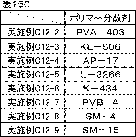
[実施例C12-1a]分散剤caのみ
表151に示す通り、実施例C12-1で用いたポリマー分散剤PVA-103を分散剤caに置き換えて分散剤を分散剤caのみとした以外は、実施例C12-1aと同様にして炭素材料分散液、炭素材料分散ワニス、正極合剤ペースト、電極を作製した。
表151に示す通り、実施例C12-1で用いたポリマー分散剤PVA-103を分散剤caに置き換えて分散剤を分散剤caのみとした以外は、実施例C12-1aと同様にして炭素材料分散液、炭素材料分散ワニス、正極合剤ペースト、電極を作製した。
[比較例C12-1]分散剤種の比較-1
表151に示す通り、実施例C12-1aで用いた分散剤caを分散剤eaに置き換えた以外は、実施例C12-1aと同様にして炭素材料分散液、炭素材料分散ワニス、正極合剤ペースト、電極を作製した。
表151に示す通り、実施例C12-1aで用いた分散剤caを分散剤eaに置き換えた以外は、実施例C12-1aと同様にして炭素材料分散液、炭素材料分散ワニス、正極合剤ペースト、電極を作製した。
[比較例C12-2]分散剤種の比較-2
表151に示す通り、実施例C12-1で用いた分散剤caを分散剤eaに置き換えた以外は、実施例C12-1と同様にして炭素材料分散液、炭素材料分散ワニス、正極合剤ペースト、電極を作製した。
表151に示す通り、実施例C12-1で用いた分散剤caを分散剤eaに置き換えた以外は、実施例C12-1と同様にして炭素材料分散液、炭素材料分散ワニス、正極合剤ペースト、電極を作製した。
[比較例C12-3、12-4]分散剤種の比較-3
比較例C12-2で用いたPVA-103の代わりに、表151に示したポリマー分散剤をそれぞれ使用した以外は、比較例C12-2と同様にして炭素材料分散液、炭素材料分散ワニス、正極合剤ペースト、電極を作製した。
比較例C12-2で用いたPVA-103の代わりに、表151に示したポリマー分散剤をそれぞれ使用した以外は、比較例C12-2と同様にして炭素材料分散液、炭素材料分散ワニス、正極合剤ペースト、電極を作製した。

<評価結果>
実施例C12-1~C12-9、実施例C12-1a、比較例C12-1~C12-4で調製した炭素材料分散液、炭素材料分散ワニス、正極合剤ペーストは、いずれも良好な分散状態であり、1か月経時後も沈降や増粘はなかった。
実施例C12-1~C12-9、実施例C12-1a、比較例C12-1~C12-4で調製した炭素材料分散液、炭素材料分散ワニス、正極合剤ペーストは、いずれも良好な分散状態であり、1か月経時後も沈降や増粘はなかった。
実施例C12-1~C12-9、実施例C12-1a、比較例C12-1~C12-4で作製した電極の剥離強度試験を行った。剥離強度試験の結果は、実施例C12-1aを100%としたとき、◎:200%以上、◎~○:200%未満175%以上、○:175%未満150%以上、○~△:150%未満120%以上、△:120%未満80%以上、とした。以下、正極合材において、溶剤が水である系の剥離強度試験の結果は、これに従うものとする。その結果を表152に示す。分散剤eaのみを用いた比較例C12-1と比較して、各種ポリマー分散剤を併用した比較例C12-2~C12-4は剥離強度がいずれも若干向上した。これは、膜形成能がない低分子の分散剤eaの代わりに膜形成に関与できるポリマー成分が入ったことによって若干ではあるが向上したものによると考えられる。一方、各種ポリマー分散剤を併用した実施例C12-1~C12-9を比較すると、いずれも大幅な向上が見られた。

[実施例C12-10~C12-88]
剥離強度向上効果が、一般式(1)で示される他のトリアジン誘導体でも得られるか確認するために、同様に試験を行った。実施例C12-1で使用した分散剤、ポリマー分散剤を表153に示した分散剤、ポリマー分散剤にそれぞれ置き換えた以外は、実施例C12-1と同様にして炭素材料分散液、炭素材料分散ワニス、正極合剤ペースト、電極を作製し、剥離強度試験を行った。
剥離強度向上効果が、一般式(1)で示される他のトリアジン誘導体でも得られるか確認するために、同様に試験を行った。実施例C12-1で使用した分散剤、ポリマー分散剤を表153に示した分散剤、ポリマー分散剤にそれぞれ置き換えた以外は、実施例C12-1と同様にして炭素材料分散液、炭素材料分散ワニス、正極合剤ペースト、電極を作製し、剥離強度試験を行った。

[実施例C12-89]ポリマー分散剤の併用
表154に示す通り、実施例C12-1で用いたPVA-103のさらに半量をSM-15に置き換えた以外は、実施例C12-1と同様にして炭素材料分散液、炭素材料分散ワニス、正極合剤ペースト、電極を作製し、剥離強度試験を行った。
表154に示す通り、実施例C12-1で用いたPVA-103のさらに半量をSM-15に置き換えた以外は、実施例C12-1と同様にして炭素材料分散液、炭素材料分散ワニス、正極合剤ペースト、電極を作製し、剥離強度試験を行った。
[実施例C12-90、C12-91]ポリマー分散剤の併用-2
実施例C12-89で用いたPVA-103の代わりに、表154に示したポリマー分散剤をそれぞれ使用した以外は、実施例C12-89と同様にして炭素材料分散液、炭素材料分散ワニス、正極合剤ペースト、電極を作製し、剥離強度試験を行った。
実施例C12-89で用いたPVA-103の代わりに、表154に示したポリマー分散剤をそれぞれ使用した以外は、実施例C12-89と同様にして炭素材料分散液、炭素材料分散ワニス、正極合剤ペースト、電極を作製し、剥離強度試験を行った。
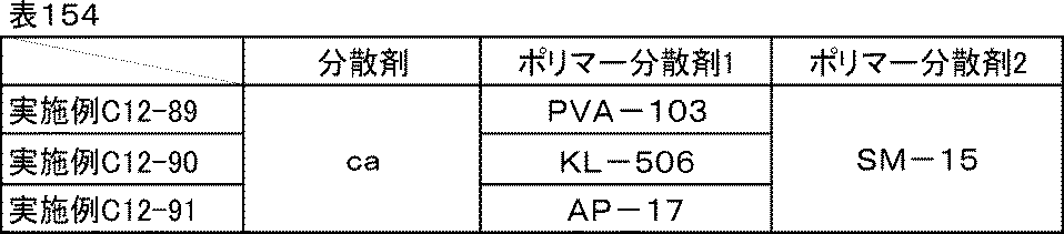
[比較例C12-5]
表155に示す通り、実施例C12-1aで用いた分散剤caを分散剤ebに置き換えた以外は、実施例C12-1aと同様にして炭素材料分散液、炭素材料分散ワニス、正極合剤ペースト、電極を作製し、剥離強度試験を行った。
表155に示す通り、実施例C12-1aで用いた分散剤caを分散剤ebに置き換えた以外は、実施例C12-1aと同様にして炭素材料分散液、炭素材料分散ワニス、正極合剤ペースト、電極を作製し、剥離強度試験を行った。
[比較例C12-6、C12-7]
実施例C12-1で使用した分散剤ca、ポリマー分散剤PVA-103を表155に示した分散剤、ポリマー分散剤にそれぞれ置き換えた以外は、実施例C12-1と同様にして炭素材料分散液、炭素材料分散ワニス、正極合剤ペースト、電極を作製し、剥離強度試験を行った。
実施例C12-1で使用した分散剤ca、ポリマー分散剤PVA-103を表155に示した分散剤、ポリマー分散剤にそれぞれ置き換えた以外は、実施例C12-1と同様にして炭素材料分散液、炭素材料分散ワニス、正極合剤ペースト、電極を作製し、剥離強度試験を行った。

<評価結果>
実施例C12-10~C12-91、実施例C12-1a、比較例C12-5~C12-7で作製した電極の剥離強度試験結果を表156に示す。分散剤eaの場合と同様に、分散剤ebと各種ポリマー分散剤を併用しても若干の剥離強度向上しかしなかったが、分散剤cb~deの場合は、分散剤caと同様に、各種ポリマー分散剤を併用することで大幅な剥離強度の向上が確認できた。
実施例C12-10~C12-91、実施例C12-1a、比較例C12-5~C12-7で作製した電極の剥離強度試験結果を表156に示す。分散剤eaの場合と同様に、分散剤ebと各種ポリマー分散剤を併用しても若干の剥離強度向上しかしなかったが、分散剤cb~deの場合は、分散剤caと同様に、各種ポリマー分散剤を併用することで大幅な剥離強度の向上が確認できた。
この効果は一般式(1)で示されるトリアジン誘導体に特有であることから、酸性官能基を有するアリーレン基と、フェノール性水酸基2つがひとつのトリアジン環に直結している構造によって、ポリマー分散剤との間に水素結合などの強い分子間力が作用したことによると考えられる。

続いてリチウムイオン二次電池正極評価用のセルを組み立て、イオン抵抗、反応抵抗、室温レート特性、低温放電特性、サイクル特性の評価を行った。
<リチウムイオン二次電池正極評価用セルの組み立て>
[実施例C13-1~C13-91][比較例C13-1、C13-2][実施例C13-1a]
実施例C2-1において、実施例C1-1で作製した電極を用いた代わりに、表157に示した電極をそれぞれ用いた以外は、実施例C2-1と同様の方法でリチウムイオン二次電池正極評価用のセルを組み立て、イオン抵抗、反応抵抗、室温レート特性、低温放電特性、サイクル特性の評価を行った。
[実施例C13-1~C13-91][比較例C13-1、C13-2][実施例C13-1a]
実施例C2-1において、実施例C1-1で作製した電極を用いた代わりに、表157に示した電極をそれぞれ用いた以外は、実施例C2-1と同様の方法でリチウムイオン二次電池正極評価用のセルを組み立て、イオン抵抗、反応抵抗、室温レート特性、低温放電特性、サイクル特性の評価を行った。
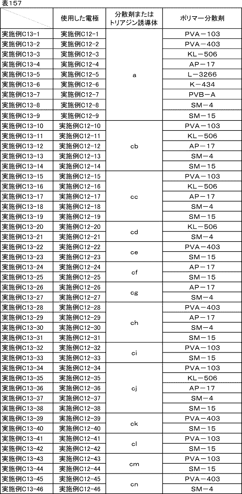
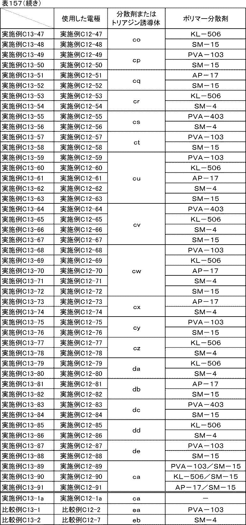
[比較例C13-3]
実施例C12-1で使用した分散剤ca、ポリマー分散剤PVA-103を水に置き換えた以外は、実施例C12-1と同様にして炭素材料分散液、炭素材料分散ワニス、正極合剤ペースト、電極を作製した。その電極を、実施例C13-1において、実施例C12-1で作製した電極の代わりに使用し、実施例C13-1と同様の方法でリチウムイオン二次電池正極評価用のセルを組み立て、イオン抵抗、反応抵抗、室温レート特性、低温放電特性、サイクル特性の評価を行った。
実施例C12-1で使用した分散剤ca、ポリマー分散剤PVA-103を水に置き換えた以外は、実施例C12-1と同様にして炭素材料分散液、炭素材料分散ワニス、正極合剤ペースト、電極を作製した。その電極を、実施例C13-1において、実施例C12-1で作製した電極の代わりに使用し、実施例C13-1と同様の方法でリチウムイオン二次電池正極評価用のセルを組み立て、イオン抵抗、反応抵抗、室温レート特性、低温放電特性、サイクル特性の評価を行った。
<評価結果>
実施例C13-1~C13-91、比較例C13-1~C13-3、実施例C13-1aのイオン抵抗、反応抵抗、室温レート特性、低温放電特性、サイクル特性の評価結果を表158に示す。
実施例C13-1~C13-91、比較例C13-1~C13-3、実施例C13-1aのイオン抵抗、反応抵抗、室温レート特性、低温放電特性、サイクル特性の評価結果を表158に示す。
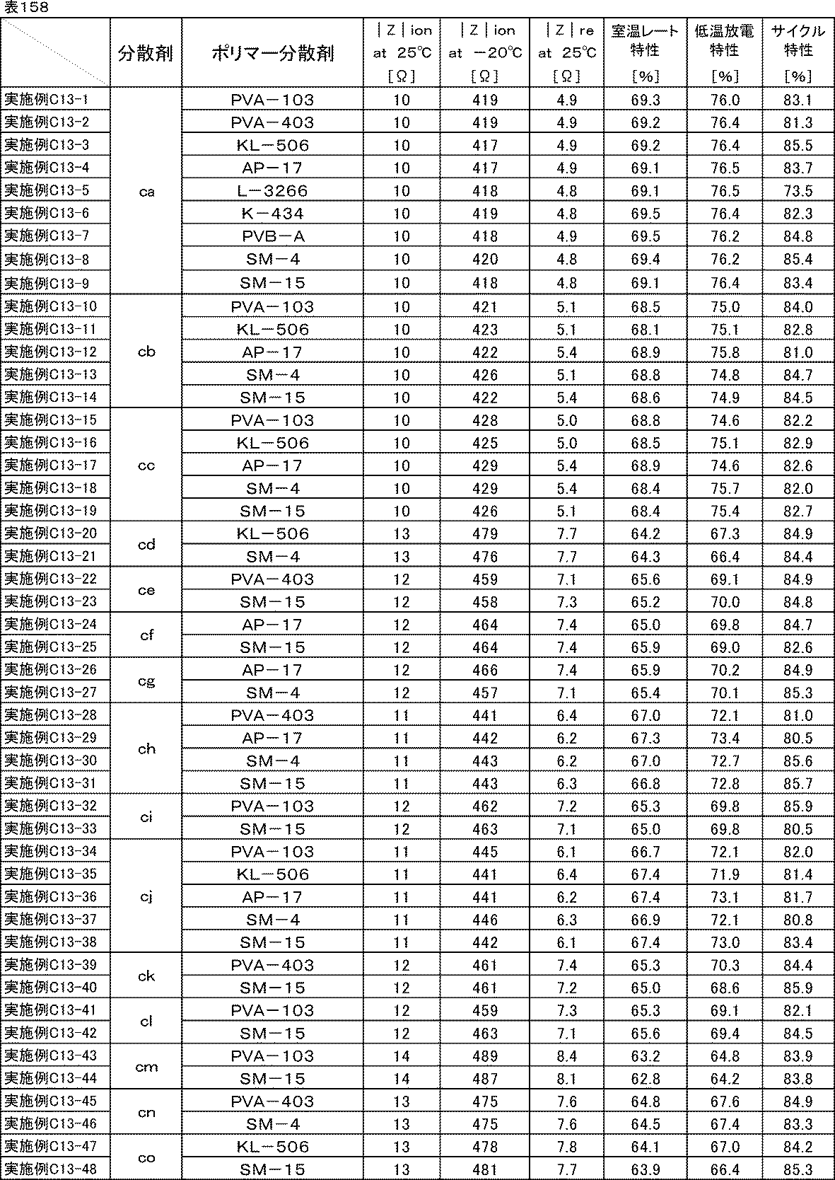

表158からわかる通り、分散剤ca~deを用いた実施例C13-1~13-91、実施例C13-1aの正極は室温および-20℃のイオン抵抗、反応抵抗、室温レート特性、低温放電特性の全てにおいて、分散剤ea、ebとポリマー分散剤を用いた比較例C13-1、13-2や分散剤を用いない比較例C13-3の正極と比べて非常に優れていた。
また、分散剤ca~deとポリマー分散剤を用いた実施例C13-1~13-91の正極は、分散剤ea、ebとポリマー分散剤を用いた比較例C13-1、13-2や分散剤を用いない比較例C13-3の正極と比べてサイクル特性が大幅に向上した。
このことから、溶剤を水とした場合でも同じ効果が得られることが確認できた。
この出願は、2017年5月12日に出願された特願2017-95486、2017年11月1日に出願された特願2017-211690及び2017年12月26日に出願された特願2017-250110を基礎とする優先権を主張し、その開示の全てをここに取り込む。
Claims (15)
- 下記一般式(1)で表されるトリアジン誘導体と、アミンまたは無機塩基とを含む分散剤。

R1が少なくとも-NHC(=O)-を含む置換基を有するフェニル基、ベンゾイミダゾール基、置換基を有してもよいインドール基または置換基を有してもよいピラゾール基である] - 前記トリアジン誘導体に対する前記アミンの含有量が0.1~5モル当量である、請求項1記載の分散剤。
- 前記トリアジン誘導体に対する前記アミンの含有量が0.3~2モル当量である、請求項1記載の分散剤。
- 前記トリアジン誘導体に対する前記無機塩基の含有量が0.1~1モル当量である、請求項1記載の分散剤。
- 請求項1~4のいずれか一項に記載の分散剤と、ポリマー分散剤とを含有する、分散剤組成物。
- 前記ポリマー分散剤が水酸基を有する、請求項5記載の分散剤組成物。
- 前記ポリマー分散剤が、ポリビニルアルコール系樹脂および/またはセルロース系樹脂である、請求項5または6記載の分散剤組成物。
- 請求項1~4のいずれか一項に記載の分散剤と、炭素材料と、溶剤とを含有する、分散組成物。
- 請求項5~7のいずれか一項に記載の分散剤組成物と、炭素材料と、溶剤とを含有する、分散組成物。
- 更に、バインダーを含有する、請求項8または9記載の分散組成物。
- 請求項8~10のいずれか一項に記載の分散組成物が、更に、活物質を含有する、電池用分散組成物。
- 前記トリアジン誘導体と、アミンまたは無機塩基とを含む分散剤の含有量が、前記活物質表面積1m2に対して0.1~200mgである、請求項11記載の電池用分散組成物。
- 集電体上に、請求項11または12記載の電池用分散組成物より形成されてなる合剤層を備える、電極。
- 請求項13記載の電極と、非水電解液とを備える、電池。
- 前記非電解液1mlに対する、前記トリアジン誘導体と、アミンまたは無機塩基とを含む分散剤の含有量が、10μg~60mgである、請求項14記載の電池。
Priority Applications (2)
| Application Number | Priority Date | Filing Date | Title |
|---|---|---|---|
| CN201880030079.9A CN110603089B (zh) | 2017-05-12 | 2018-05-11 | 分散剂、分散剂组合物、分散组合物、电池用分散组合物、电极以及电池 |
| US16/612,409 US11352511B2 (en) | 2017-05-12 | 2018-05-11 | Dispersant, dispersant composition, dispersion composition for batteries, electrode and battery |
Applications Claiming Priority (6)
| Application Number | Priority Date | Filing Date | Title |
|---|---|---|---|
| JP2017-095486 | 2017-05-12 | ||
| JP2017095486A JP6274343B1 (ja) | 2017-05-12 | 2017-05-12 | 分散剤、分散組成物、電池用分散組成物、電極、電池 |
| JP2017-211690 | 2017-11-01 | ||
| JP2017211690A JP6380642B1 (ja) | 2017-11-01 | 2017-11-01 | 分散剤、分散組成物、電池用分散組成物、電極、電池 |
| JP2017250110A JP6375050B1 (ja) | 2017-12-26 | 2017-12-26 | 電池用組成物、電池用分散組成物、電極、電池 |
| JP2017-250110 | 2017-12-26 |
Publications (1)
| Publication Number | Publication Date |
|---|---|
| WO2018207933A1 true WO2018207933A1 (ja) | 2018-11-15 |
Family
ID=64105525
Family Applications (1)
| Application Number | Title | Priority Date | Filing Date |
|---|---|---|---|
| PCT/JP2018/018420 Ceased WO2018207933A1 (ja) | 2017-05-12 | 2018-05-11 | 分散剤、分散剤組成物、電池用分散組成物、電極、および電池 |
Country Status (3)
| Country | Link |
|---|---|
| US (1) | US11352511B2 (ja) |
| CN (1) | CN110603089B (ja) |
| WO (1) | WO2018207933A1 (ja) |
Cited By (1)
| Publication number | Priority date | Publication date | Assignee | Title |
|---|---|---|---|---|
| JP2019107623A (ja) * | 2017-12-19 | 2019-07-04 | 花王株式会社 | 分散剤組成物 |
Families Citing this family (5)
| Publication number | Priority date | Publication date | Assignee | Title |
|---|---|---|---|---|
| US11508955B2 (en) * | 2018-09-28 | 2022-11-22 | Jiangsu Cnano Technology Co., Ltd. | Conductive carbon material dispersing agent and high-conductivity slurry for lithium battery |
| US20210112669A1 (en) * | 2019-10-09 | 2021-04-15 | National Taiwan University Of Science And Technology | Conductive slurry and plating method using the same |
| CN113728471B (zh) * | 2020-03-31 | 2023-09-05 | 宁德新能源科技有限公司 | 负极材料、负极极片、电化学装置和电子装置 |
| CN117117170B (zh) * | 2023-08-30 | 2024-09-06 | 安徽皓飞新材料有限公司 | 一种三元正极浆料及其制备方法和应用 |
| CN117637997A (zh) * | 2023-12-14 | 2024-03-01 | 湖北亿纬动力有限公司 | 一种正极极片及其制备方法和应用 |
Citations (6)
| Publication number | Priority date | Publication date | Assignee | Title |
|---|---|---|---|---|
| JPS5060528A (ja) * | 1973-09-29 | 1975-05-24 | ||
| JP2010061932A (ja) * | 2008-09-03 | 2010-03-18 | Toyo Ink Mfg Co Ltd | 電池用組成物 |
| JP2013139488A (ja) * | 2010-04-16 | 2013-07-18 | Toyo Ink Sc Holdings Co Ltd | 顔料組成物、顔料分散体及びそれを用いたインクジェットインキ、電子写真用トナー |
| JP2015101615A (ja) * | 2013-11-22 | 2015-06-04 | 東洋インキScホールディングス株式会社 | カーボンブラック分散液およびその利用 |
| JP2015191760A (ja) * | 2014-03-28 | 2015-11-02 | 東洋インキScホールディングス株式会社 | 分散剤、分散組成物、電池用分散組成物、電池 |
| JP2017174708A (ja) * | 2016-03-25 | 2017-09-28 | 東洋インキScホールディングス株式会社 | 分散組成物、電池用分散組成物、電池 |
Family Cites Families (10)
| Publication number | Priority date | Publication date | Assignee | Title |
|---|---|---|---|---|
| FR2574086B1 (fr) * | 1984-12-03 | 1987-07-17 | Coatex Sa | Agent dispersant hydrosoluble pour compositions aqueuses pigmentees |
| DE3818183A1 (de) * | 1988-05-28 | 1989-12-07 | Basf Ag | Verfahren zum faerben von leder mit pigmenten |
| JP4235788B2 (ja) | 2001-11-19 | 2009-03-11 | 御国色素株式会社 | カーボンブラックスラリー及びリチウム二次電池用電極 |
| JP4314223B2 (ja) * | 2004-09-24 | 2009-08-12 | 株式会社東芝 | 回生用蓄電システム、蓄電池システムならびに自動車 |
| KR20080032210A (ko) * | 2005-07-22 | 2008-04-14 | 캐보트 코포레이션 | 안료 조성물의 제조 방법 |
| US20100028773A1 (en) | 2007-03-05 | 2010-02-04 | Toyo Ink Mfg. Co., Ltd. | Composition for battery |
| JP5352071B2 (ja) * | 2007-09-28 | 2013-11-27 | 富士フイルム株式会社 | 有機顔料ナノ粒子の非水性分散物、それにより得られる着色感光性樹脂組成物、それを用いたカラーフィルタ及び液晶表示装置 |
| CN101981125B (zh) * | 2008-03-31 | 2014-09-10 | 帝斯曼知识产权资产管理有限公司 | 含有可自动氧化脂肪酸改性聚酯的水性乳液涂料组合物 |
| JP5533057B2 (ja) | 2010-03-11 | 2014-06-25 | 東洋インキScホールディングス株式会社 | カーボンブラック分散液 |
| KR102217137B1 (ko) * | 2013-02-27 | 2021-02-19 | 토요잉크Sc홀딩스주식회사 | 카본블랙 분산액 및 그의 이용 |
-
2018
- 2018-05-11 CN CN201880030079.9A patent/CN110603089B/zh active Active
- 2018-05-11 WO PCT/JP2018/018420 patent/WO2018207933A1/ja not_active Ceased
- 2018-05-11 US US16/612,409 patent/US11352511B2/en active Active
Patent Citations (6)
| Publication number | Priority date | Publication date | Assignee | Title |
|---|---|---|---|---|
| JPS5060528A (ja) * | 1973-09-29 | 1975-05-24 | ||
| JP2010061932A (ja) * | 2008-09-03 | 2010-03-18 | Toyo Ink Mfg Co Ltd | 電池用組成物 |
| JP2013139488A (ja) * | 2010-04-16 | 2013-07-18 | Toyo Ink Sc Holdings Co Ltd | 顔料組成物、顔料分散体及びそれを用いたインクジェットインキ、電子写真用トナー |
| JP2015101615A (ja) * | 2013-11-22 | 2015-06-04 | 東洋インキScホールディングス株式会社 | カーボンブラック分散液およびその利用 |
| JP2015191760A (ja) * | 2014-03-28 | 2015-11-02 | 東洋インキScホールディングス株式会社 | 分散剤、分散組成物、電池用分散組成物、電池 |
| JP2017174708A (ja) * | 2016-03-25 | 2017-09-28 | 東洋インキScホールディングス株式会社 | 分散組成物、電池用分散組成物、電池 |
Cited By (1)
| Publication number | Priority date | Publication date | Assignee | Title |
|---|---|---|---|---|
| JP2019107623A (ja) * | 2017-12-19 | 2019-07-04 | 花王株式会社 | 分散剤組成物 |
Also Published As
| Publication number | Publication date |
|---|---|
| CN110603089A (zh) | 2019-12-20 |
| US20200131379A1 (en) | 2020-04-30 |
| US11352511B2 (en) | 2022-06-07 |
| CN110603089B (zh) | 2021-09-14 |
Similar Documents
| Publication | Publication Date | Title |
|---|---|---|
| JP6524479B1 (ja) | 化合物、分散剤、電池用分散組成物、電極、電池 | |
| CN110603089B (zh) | 分散剂、分散剂组合物、分散组合物、电池用分散组合物、电极以及电池 | |
| JP6380642B1 (ja) | 分散剤、分散組成物、電池用分散組成物、電極、電池 | |
| JP6274343B1 (ja) | 分散剤、分散組成物、電池用分散組成物、電極、電池 | |
| JP6743954B1 (ja) | 導電材分散体およびその利用 | |
| JP6028286B2 (ja) | 二次電池電極形成用エマルションバインダー、二次電池電極形成用合材インキ、二次電池電極、及び二次電池 | |
| CN103597637B (zh) | 二次电池电极形成用组合物、二次电池电极以及二次电池 | |
| JP2014194927A (ja) | 合材スラリーおよびその製造方法とそれを用いた電極、電池 | |
| KR102008807B1 (ko) | 축전 디바이스용 집전체, 그 제조 방법, 및 그 제조에 사용하는 도포 시공액 | |
| JP2014203555A (ja) | 二次電池電極形成用組成物、その製造方法、二次電池電極、及び二次電池 | |
| JP5446178B2 (ja) | リチウム二次電池用正極合剤ペースト | |
| JP5900111B2 (ja) | 二次電池電極形成用組成物、二次電池電極、及び二次電池 | |
| JP6269013B2 (ja) | 蓄電デバイス電極形成用組成物、蓄電デバイス電極、及び蓄電デバイス | |
| JP2020071932A (ja) | 電池用カーボンブラック合剤スラリーの製造方法とその利用 | |
| JP6036261B2 (ja) | 二次電池電極形成用組成物、二次電池電極、及び二次電池 | |
| JP6314491B2 (ja) | 二次電池電極形成用組成物、二次電池用電極および二次電池 | |
| JP6036260B2 (ja) | 二次電池電極形成用組成物、二次電池電極、及び二次電池 | |
| EP4624419A1 (en) | Carbon material, carbon material dispersion composition, mixture slurry, electrode film, secondary battery, and vehicle | |
| JP2020021629A (ja) | 電池用カーボンブラック分散組成物およびその利用 | |
| JP6740566B2 (ja) | 蓄電デバイス電極形成用組成物、蓄電デバイス電極、及び蓄電デバイス | |
| JP5136303B2 (ja) | キャパシタ用組成物 | |
| JP5764804B2 (ja) | リチウムイオン二次電池正極用合材ペースト | |
| JP2014135198A (ja) | 二次電池電極形成用組成物、二次電池用電極および二次電池 | |
| JP2015191760A (ja) | 分散剤、分散組成物、電池用分散組成物、電池 | |
| JP2020021632A (ja) | カーボンブラック分散組成物およびその利用 |
Legal Events
| Date | Code | Title | Description |
|---|---|---|---|
| 121 | Ep: the epo has been informed by wipo that ep was designated in this application |
Ref document number: 18798042 Country of ref document: EP Kind code of ref document: A1 |
|
| NENP | Non-entry into the national phase |
Ref country code: DE |
|
| 122 | Ep: pct application non-entry in european phase |
Ref document number: 18798042 Country of ref document: EP Kind code of ref document: A1 |