WO2018207871A1 - バンパーリインフォースメント - Google Patents
バンパーリインフォースメント Download PDFInfo
- Publication number
- WO2018207871A1 WO2018207871A1 PCT/JP2018/018128 JP2018018128W WO2018207871A1 WO 2018207871 A1 WO2018207871 A1 WO 2018207871A1 JP 2018018128 W JP2018018128 W JP 2018018128W WO 2018207871 A1 WO2018207871 A1 WO 2018207871A1
- Authority
- WO
- WIPO (PCT)
- Prior art keywords
- bumper reinforcement
- reinforcing member
- main body
- collision load
- central portion
- Prior art date
- Legal status (The legal status is an assumption and is not a legal conclusion. Google has not performed a legal analysis and makes no representation as to the accuracy of the status listed.)
- Ceased
Links
Images




Classifications
-
- B—PERFORMING OPERATIONS; TRANSPORTING
- B60—VEHICLES IN GENERAL
- B60R—VEHICLES, VEHICLE FITTINGS, OR VEHICLE PARTS, NOT OTHERWISE PROVIDED FOR
- B60R19/00—Wheel guards; Radiator guards, e.g. grilles; Obstruction removers; Fittings damping bouncing force in collisions
- B60R19/02—Bumpers, i.e. impact receiving or absorbing members for protecting vehicles or fending off blows from other vehicles or objects
- B60R19/04—Bumpers, i.e. impact receiving or absorbing members for protecting vehicles or fending off blows from other vehicles or objects formed from more than one section in a side-by-side arrangement
-
- B—PERFORMING OPERATIONS; TRANSPORTING
- B60—VEHICLES IN GENERAL
- B60R—VEHICLES, VEHICLE FITTINGS, OR VEHICLE PARTS, NOT OTHERWISE PROVIDED FOR
- B60R19/00—Wheel guards; Radiator guards, e.g. grilles; Obstruction removers; Fittings damping bouncing force in collisions
- B60R19/02—Bumpers, i.e. impact receiving or absorbing members for protecting vehicles or fending off blows from other vehicles or objects
- B60R19/18—Bumpers, i.e. impact receiving or absorbing members for protecting vehicles or fending off blows from other vehicles or objects characterised by the cross-section; Means within the bumper to absorb impact
Definitions
- the present invention relates to bumper reinforcement.
- the present invention relates to a bumper reinforcement that is disposed as a core material of a bumper structure that is provided at the front or rear of an automobile and receives a load at the time of a collision.
- a bumper structure that receives a collision load in the event of a vehicle collision is provided at the front or rear of the automobile body.
- the bumper structure is provided with bumper reinforcement as a core material.
- the bumper reinforcement is arranged in a long shape in the width direction of the vehicle body, and is supported by being connected to a frame member of the vehicle body by a bumper support structure at both ends in the width direction of the vehicle body.
- a crash box that normally absorbs energy during a vehicle collision is used. When the crash box is not used, the bumper reinforcement is connected and coupled to the side member, and energy is absorbed by the side member.
- bumper reinforcement has a form which consists of a main-body member and a reinforcement member.
- the main body member includes a main body member having a hat-shaped cross section, and a planar plate member that is disposed so as to close the opening portion on the opening side of the main body member and has the main body member closed to have a cross-sectional shape.
- This main body member is a long member, and its longitudinal direction is arranged in the width direction of the automobile.
- the reinforcing member is disposed inside the main body member having a closed cross-sectional shape for reinforcement when a collision load is input to the center of the main body member.
- the arrangement position is the central portion in the longitudinal direction of the main body member which is a long member.
- the cross section of the reinforcing member is formed in a quadrangle that faces the internal shape of the main body member.
- buckling breakage
- the collision load received on both sides of the bumper reinforcement can support a load as designed. it can.
- buckling occurs at a position deviated from the center to the left and right. If buckling occurs in such a biased position, a target impact load of a predetermined magnitude may not be supported by the bumper reinforcement.
- One aspect of the present invention is a bumper reinforcement for an automobile, comprising an elongated body member disposed in the automobile in the vehicle width direction, the body member having a hat-shaped main body member, A planar plate member disposed on the opening side of the main body member so as to close the opening of the main body member and having a cross-sectional shape that closes the main body member, and the planar plate member is provided on a collision load input side.
- It is a bumper reinforcement arranged in the automobile so that a reinforcing member having a quadrangular cross section is arranged inside the longitudinal center of the main body member, and the rigidity of the reinforcing member in the direction in which the collision load is input is The reinforcing member is raised at the central portion from both side portions.
- the bumper reinforcement can support a collision load having a predetermined size.
- the constituent surface that constitutes the reinforcing member and that forms each side of the quadrangular section has a convex surface that is perpendicular to the direction in which the collision load is input or It has a concave bead.
- high rigidity can be achieved with a relatively simple structure called a bead by adopting the above configuration.
- the width of the reinforcing member perpendicular to the direction in which the collision load is input and the longitudinal direction is wider at the central portion than the both side portions.
- high rigidity can be achieved with a relatively simple structure in which the width of the reinforcing member is changed by adopting the above configuration.
- the constituent surface that forms the reinforcing member and forms each side of the quadrangular section has a convex surface or a concave surface that is perpendicular to the direction in which the collision load is input.
- the width of the reinforcing member that has a bead and is perpendicular to the direction in which the collision load is input and the longitudinal direction is wider at the central portion than at the both side portions.
- the bead has a convex shape.
- the rigidity in the collision load direction can be formed stronger than the concave bead.
- the constituent surface of the reinforcing member on which the bead is formed is the foremost constituent surface in the direction in which the collision load is input among the constituent surfaces forming the sides of the quadrangular section.
- the collision load can be efficiently supported by the frontmost component surface.
- a collision load of a predetermined magnitude is applied so as to reliably buckle in the center. It can be supported.
- FIG. 4 is a cross-sectional view of the bumper reinforcement of FIG. 2 taken along the line IV-IV. It is the perspective view which looked at the reinforcement member single item from the diagonally upper left back.
- FIG. 6 is a cross-sectional view of the reinforcing member of FIG. 5 taken along line VI-VI.
- FIG. 6 is a cross-sectional view of the reinforcing member of FIG. 5 taken along line VII-VII.
- the term regarding the direction used by the following description represents the direction on the basis of the motor vehicle with which the bumper reinforcement was mounted
- the indications “right” and “left” indicate a direction relative to the automobile.
- the indications “front” and “rear” attached to the heads of the names of the members and parts indicate relative positional relationships corresponding to the forward and reverse directions of the automobile.
- “upper” and “lower” displays also indicate the relative positional relationship seen in the height direction of the automobile.
- FIG. 1 shows a bumper structure 10 arranged in an automobile.
- the bumper structure 10 is usually disposed in the vehicle width direction with respect to the vehicle body 12 at the front and rear portions of the vehicle body 12.
- the front of the vehicle body 12 is indicated by an arrow Fr
- the rear is indicated by an arrow Rr.
- the automobile compartment is formed at the position of the automobile body 12.
- the bumper structure 10 can be composed of a bumper reinforcement 14, a bumper covering member 16, and a bumper support structure 18.
- the bumper reinforcement 14 is disposed as a core material on the strength of the bumper structure 10.
- the bumper covering member 16 is disposed so as to cover the front surface of the bumper reinforcement 14.
- the bumper covering member 16 is disposed on the outermost surface of the bumper structure 10 and has a structure in consideration of appearance. Usually, it is formed of a resin suitable for molding a design.
- the bumper support structure 18 is disposed between the frame member (not shown) of the vehicle body 12 and the bumper reinforcement 14 at both ends of the bumper reinforcement 14 in the longitudinal direction (width direction when viewed from the vehicle body 12). Is done.
- the bumper support structure 18 transmits and supports the collision load received by the bumper reinforcement 14 to the automobile body 12.
- the bumper support structure 18 may be constituted by components capable of absorbing collision energy called a crash box and a side member.
- the bumper reinforcement 14 is disposed at the front portion of the automobile body 12.
- the collision load F acting on the center of the bumper structure 10 due to the frontal collision of the automobile is first received by the bumper covering member 16 and then supported by the bumper reinforcement 14.
- the load acting on the bumper reinforcement 14 is supported by the vehicle body 12 via a crash box as a bumper support structure 18 disposed at both ends of the bumper reinforcement 14. At this time, the crash box absorbs the collision energy.
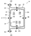
- the bumper reinforcement 14 can be composed of a main body member 20 and a reinforcing member 30 as shown in the cross-sectional view of FIG.
- the main body member 20 can be composed of a main member 22 having a hat-shaped cross section and a planar plate member 24.
- the planar plate member 24 is disposed so as to close the opening of the main member 22 having a hat-shaped cross section, and the main body member 20 is closed to have a cross-sectional shape.
- the reinforcing member 30 has a rectangular frame shape and is disposed inside the main body member 20 having a closed cross-sectional shape.
- the bumper reinforcement 14 is disposed so that the collision load F is input to the planar plate member 24 side.
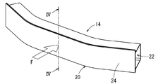
- FIG. 2 is a perspective view of the entire bumper reinforcement 14 as viewed obliquely from the upper left.
- the bumper reinforcement 14 can be formed in a curved shape with both ends in the longitudinal direction retracted.
- FIG. 4 described above is a cross-sectional view of the bumper reinforcement 14 of FIG. 2 taken along the line IV-IV.
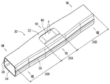
- FIG. 3 is a perspective view of the configuration of the main body member 22 forming the main body member 20 and the reinforcing member 30 disposed in the main body member 22 as seen from the upper left side in the same manner as FIG. As shown in FIG. 3, the reinforcing member 30 is disposed at the center of the long bumper reinforcement 14.
- the range in which the reinforcing member 30 extends is within the range between the two crash boxes 18 as support structures disposed at both ends shown in FIG. Thereby, the collision load F input to the center of the bumper reinforcement 14 is supported by the rigidity of the bumper reinforcement 14 reinforced by the reinforcing member 30.
- the cross-sectional hat-shaped main member 22 constituting the main body member 20 has a rear side plate portion 22A, an upper side plate portion 22B, and a lower side plate portion 22C.
- an upper flange portion 22D extends upward as viewed in FIG. 4 on the opening side of the upper side plate portion 22B.
- a lower flange portion 22E extends downward from the opening side of the lower side plate portion 22C as viewed in FIG.
- the planar plate member 24 is applied to an upper flange portion 22D and a lower flange portion 22E formed on the opening side of the main member 22, and is joined and fixed by welds W1 and W2. Thereby, the closed cross-sectional shape of the main body member 20 is made.
- the welding is spot welding. The same applies to the welding described below.
- the main body member 22 and the planar plate member 24 constituting the main body member 20 can be made of a steel plate.
- the reinforcing member 30 shown in FIG. 5 is disposed inside the main body member 20 having a closed sectional shape as shown in FIG.
- the cross section of the reinforcing member 30 has a quadrangular frame shape as shown in FIG.
- the frame shape includes a front face plate portion 32, a rear face plate portion 34, an upper face plate portion 36, and a lower face plate portion 38.
- the upper face plate portion 36 and the lower face plate portion 38 may be divided and configured.
- the upper face plate portion 36 is divided into an upper front face plate portion 36A and an upper rear face plate portion 36B, and both of them are partially overlapped and joined at a welded portion W3.
- the lower face plate portion 38 is divided into a lower front face plate portion 38A and a lower rear face plate portion 38B, and both of them are partially overlapped and joined at a welded portion W4 to be integrated.
- the reinforcing member 30 can also be made of a steel plate, similar to the main body member 20 described above.
- the main body member 20 and the reinforcing member 30 are integrated by joining the planar plate member 24 constituting the main body member 20 and the front face plate portion 32 of the reinforcing member 30 with a welded portion W5. can do. Further, the main body member 20 and the reinforcing member 30 can also be integrated by joining the rear side plate portion 22A of the main body member 22 constituting the main body member 20 and the rear side plate portion 34 of the reinforcing member 30 with a welded portion W6. it can.
- the reinforcing member 30 is configured by integrally connecting a central portion 30A at a central position in the longitudinal direction and both side portions 30B on both sides thereof.
- 6 shows a cross section of the reinforcing member 30 of FIG. 5 taken along line VI-VI of the central portion 30A
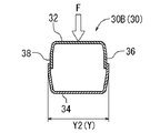
- FIG. 7 shows a cross section of the reinforcing member 30 of FIG. 5 taken along line VII-VII of both side portions 30B.
- a convex bead 40 can be formed in the central portion 30 ⁇ / b> A in the front face plate portion 32 that is one of the constituent surfaces of the reinforcing member 30. That is, the front face plate portion 32 has a bead surface shape in which the central portion in the width direction is convex upward as seen in the figure, and the surface rigidity is enhanced.
- the front face plate portion 32 has a planar shape at both side portions 30 ⁇ / b> B and is not a bead surface shape having a convex bead.
- the rigidity of the reinforcing member 30 in the direction in which the collision load is input is stronger in the central portion 30A than in the both side portions 30B.
- the constituent surfaces orthogonal to the direction in which the collision load F is input are the front face plate portion 32 and the rear face plate portion 34.
- the central portion 30A in the configuration surface has a bead surface shape.
- the front face plate portion 32 having a bead surface shape is the foremost constituent surface in the direction in which the collision load is input in the constituent surfaces constituting the reinforcing member 30.
- the reinforcing member 30 can have different widths Y at the central portion 30A and the side portions 30B as shown in FIGS. Specifically, the width Y1 of the central portion 30A shown in FIG. 6 is formed wide, while the width Y2 of the side portions 30B shown in FIG. 7 is formed narrow. That is, Y1> Y2. As described above, the reinforcing member 30 is set to be relatively wider in the central portion 30A than in the both side portions 30B, and has relatively high rigidity. Due to the difference in width between the central portion 30A and the side portions 30B, the rigidity of the reinforcing member 30 in the direction in which the collision load F is input is higher in the central portion 30A than in the side portions 30B.
- the change from the wide width Y1 of the central portion 30A to the narrow width Y2 of the side portions 30B may be changed so as to be gradually narrowed in the range of the side portions 30B.
- it may be changed stepwise at the boundary between the central portion 30A and both side portions 30B, in such a configuration, stress concentration tends to occur at the stepped portion.
- the bumper reinforcement 14 includes the main body member 20 and the reinforcing member 30.
- the central portion 30A of the reinforcing member 30 is formed with higher rigidity than both side portions 30B, stress concentration due to the collision load input to the bumper reinforcement 14 occurs in the central portion of the reinforcing member 30 having high rigidity. .
- the buckling phenomenon of the bumper reinforcement 14 due to the collision load F occurs in the central portion.
- This buckling phenomenon is surely performed at the central portion due to the shape of the reinforcing member 30 described above, even if the support strength of the bumper support structure 18 at both ends of the bumper reinforcement 14 is slightly different. Thereby, the collision load can be effectively supported in a balanced manner at the left and right positions of the bumper reinforcement 14. For this reason, as pointed out as a conventional problem, peeling does not occur in the welded portion, and the support load of the bumper reinforcement 14 does not decrease.
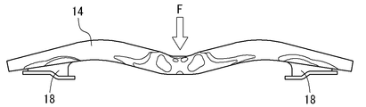
- FIG. 9 shows an example of the buckling state of the bumper reinforcement 14 pointed out as a conventional problem.
- the stress concentration location due to the collision load is shifted to the left as viewed in the figure from the center, peeling of the weld occurs, and the support load of the bumper reinforcement 14 decreases.
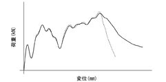
- FIG. 10 is a diagram showing the load and displacement characteristics of the bumper reinforcement 14 in the embodiment described above.
- the reinforcing member 30 of this embodiment has both a bead surface shape and a wide shape.
- the solid line is the case of the present embodiment
- the broken line is the case of the conventional configuration.
- the load can be supported in a certain displacement range thereafter. This is also one of the features of this embodiment.
- the bead 40 has a convex shape.
- a concave shape may be used.
- the convex bead has the advantage that the rigidity can be increased.
- the bead is set in the front face plate portion 32.
- the bead may be set in the rear face plate portion 34.
- the bead may be set for both the parts 32 and 34.
- the reinforcing member 30 is disposed between the positions where the two crash boxes are disposed.
- the reinforcing member 30 is extended to the outside of the position where the crash box is disposed. Also good.
- the joining means between the main body member 20 and the reinforcing member 30 is welding.
- mechanical joining means such as a rivet may be used.
- the welding is spot welding.
- arc welding laser welding, or other welding means may be used.
- the material of the main body member 20 and the reinforcing member 30 is made of a steel plate.
- the material is not limited to a steel plate as long as it is a rigid material.
Landscapes
- Engineering & Computer Science (AREA)
- Mechanical Engineering (AREA)
- Body Structure For Vehicles (AREA)
Abstract
バンパーリインフォースメントは閉じ断面形状の本体部材とその内部に配設される補強部材(30)とを有する。補強部材(30)は中央部位(30A)と両側部位(30B)とを有し、剛性が中央部位(30A)で両側部位(30B)より高められている。剛性を高めるためには、例えば中央部位(30A)をビード面形状としたり、幅広形状としたりすることができる。
Description
本発明は、バンパーリインフォースメントに関する。特に、自動車の前部または後部に装備されるバンパ構造の芯材として配設され、衝突時の荷重を受けるバンパーリインフォースメントに関する。
自動車車体の前部または後部には、車両衝突時における衝突荷重を受けるバンパ構造が備えられる。バンパ構造には芯材としてのバンパーリインフォースメントが備えられる。バンパーリインフォースメントは自動車車体の幅方向に長尺形状として配設されており、自動車車体の幅方向の両端部で自動車車体のフレーム部材にバンパ支持構造で連結されて支持される。バンパ支持構造は、通常、車両衝突時のエネルギー吸収が行われるクラッシュボックスが用いられる。なお、クラッシュボックスが用いられない場合は、バンパーリインフォースメントはサイドメンバに接続結合されて、このサイドメンバでエネルギー吸収が行われる。
バンパーリインフォースメントの構成形態は、各種形態がある。例えば、バンパーリインフォースメントは、本体部材と補強部材とからなる形態がある。この場合、本体部材は断面ハット型形状の主体部材と、この主体部材の開口側に当該開口部を閉鎖するように配設されて、当該本体部材を閉じ断面形状とする面状板部材とからなる。この本体部材は長尺部材であり、その長手方向が自動車の幅方向に配設される。
補強部材は本体部材の中央に衝突荷重が入力した際の補強のために、閉じ断面形状の本体部材の内部に配設される。その配設位置は、長尺部材である本体部材の長手方向の中央部とされる。そして、補強部材の断面は本体部材の内部形状に面する四角形に形成されている。このように本体部材と補強部材とにより構成されたバンパーリインフォースメントは、本体部材の面状板部材側が衝突荷重の入力側となるように配置される。これにより、バンパーリインフォースメントの中央に衝突荷重が入力した際に、補強部材の補強作用によってバンパーリインフォースメントの支持する荷重の増大を図っている。
他にも本発明に関連する技術は特開2008-265738号公報、特開2005-263114号公報、特開2017-47818号公報に記載されている。
上述した形態のバンパーリインフォースメントにおいては、衝突荷重がバンパーリインフォースメントの中央に入力した際の衝突荷重を支持する特性としては、当該中央で座屈(折損)が生じるようにするのが好ましい。すなわち、バンパーリインフォースメントに衝突荷重が入力した際、中央で応力集中が生じ、座屈が生じるようにすると、バンパーリインフォースメントの両側で受ける衝突荷重は設計通りの大きさの荷重を支持することができる。
ところが、バンパーリインフォースメントを両端で支持するクラッシュボックス等のバンパ支持構造の支持強度に差があると、それに伴って、中央より左右に偏った位置で座屈を生じる。このように偏った位置で座屈を生じると、狙った所定の大きさの衝突荷重をバンパーリインフォースメントで支持することができないことがある。
偏った位置で座屈を生じると、その座屈により、閉じ断面形状を形成する主体部材と面状板部材とのフランジ部の溶接部に剥離方向の力が及ぼされる。溶接はせん断には強いが剥離には弱いため、溶接部が剥がれて、主体部材と面状板部材との接合が破断する。このため、バンパーリインフォースメントの支持荷重の低下が生じることになる。
したがって、バンパーリインフォースメントを支持する両端の支持強度の相違がある場合であっても、中央で確実に座屈を生じるようにして、所定の大きさの衝突荷重を支持できるようにすることが望まれる。
本発明のひとつの側面は自動車のバンパーリインフォースメントであって、車幅方向に向けて自動車に配設される長尺形状の本体部材を備え、この本体部材が断面ハット型形状の主体部材と、該主体部材の開口側に該主体部材の開口部を閉鎖するように配設されて当該本体部材を閉じ断面形状とする面状板部材とを備え、この面状板部材が衝突荷重の入力側となるように自動車に配設されるバンパーリインフォースメントであり、本体部材における長手方向の中央部の内部に断面四角形の補強部材が配設され、この補強部材における衝突荷重が入力する方向に対する剛性が該補強部材の中央部位で両側部位より高められている。
実施形態によっては、上記の構成とすることにより、バンパーリインフォースメントの両端の支持剛性に相違があったとしても、衝突荷重が加わった際には、剛性が強い中央部位において応力集中を生じて、当該位置で座屈を生じる。これにより、バンパーリインフォースメントは所定の大きさの衝突荷重を支持することができる。
実施形態によっては、前記補強部材における中央部位の剛性を高めるために、前記補強部材を構成し断面四角形の各辺を成す構成面のうち衝突荷重が入力する方向に直交する構成面が凸形状又は凹形状のビードを有する。
実施形態によっては、上記の構成とすることによりビードという比較的簡単な構造で高剛性を達成することができる。
実施形態によっては、前記補強部材における中央部位の剛性を高めるために、衝突荷重が入力する方向と長手方向とに直交する補強部材の幅が前記中央部位で前記両側部位より幅広とされている。
実施形態によっては、上記の構成とすることにより補強部材の幅を変えるという比較的簡単な構造で高剛性を達成することができる。
実施形態によっては、上記の二つの構成を組合せることも可能である。すなわち、前記補強部材における中央部位の剛性を高めるために、前記補強部材を構成し断面四角形の各辺を成す構成面のうち衝突荷重が入力する方向に直交する構成面が凸形状又は凹形状のビードを有すると共に、衝突荷重が入力する方向と長手方向とに直交する補強部材の幅が前記中央部位で前記両側部位より幅広とされている。
実施形態によっては、上記の構成とすることにより、補強部材の中央部位の剛性を両側部位の剛性より確実に高めることが可能となる。また、両構成を上手く組合せることにより、剛性の大きさも適切に設定することもできる。
実施形態によっては、前記ビードは凸形状である。
実施形態によっては、上記の構成とすることにより凹形状のビードに比べ衝突荷重方向に対する剛性を強く形成することができる。
実施形態によっては、前記ビードが形成された補強部材の構成面は、断面四角形の各辺を成す構成面のうち衝突荷重が入力する方向の最前面の構成面である。
実施形態によっては、上記の構成とすることにより、最前面の構成面により効率よく衝突荷重を支持することができる。
本発明の各種実施形態によれば、バンパーリインフォースメントを支持する両端の支持強度の相違がある場合であっても、中央で確実に座屈を生じるようにして、所定の大きさの衝突荷重を支持できるようにすることができる。
以下、本発明の実施形態について図面を参照しながら説明する。なお、以下の説明で用いている方向に関する用語は、特にこれと異なる指示がない限り、図に描かれた向きにかかわらずバンパーリインフォースメントが装着された自動車を基準とする方向を表す。例えば、「右」「左」の表示は、自動車を基準とする方向を指す。また、各部材及び部位の名称の頭に付する「前」「後」の表示は、自動車の前進及び後進の方向に対応する相対的位置関係を示す。同様に、「上」「下」の表示も、自動車の高さ方向で見た相対的位置関係を示す。
図1は自動車に配置されたバンパ構造10を示す。バンパ構造10は、通常、自動車車体12の前部と後部に自動車車体12に対して車幅方向に配置される。図1において、自動車車体12の前方を矢印Frで示し、後方を矢印Rrで示した。自動車の車室は自動車車体12の位置に形成される。バンパ構造10は、バンパーリインフォースメント14と、バンパ被覆部材16と、バンパ支持構造18とから構成することができる。バンパーリインフォースメント14はバンパ構造10の強度上の芯材として配設される。バンパ被覆部材16はバンパーリインフォースメント14の前面を被覆するように配設される。バンパ被覆部材16はバンパ構造10の最外面に配設され、見栄えを考慮した構造とされている。通常、意匠の成形に適する樹脂で形成される。
バンパ支持構造18は、バンパーリインフォースメント14の長手方向(自動車車体12で見て幅方向)の両端部の位置で自動車車体12のフレーム部材(不図示)とバンパーリインフォースメント14との間に配設される。そして、このバンパ支持構造18によりバンパーリインフォースメント14で受ける衝突荷重を自動車車体12に伝えて支持する。実施形態によっては、バンパ支持構造18はクラッシュボックス及びサイドメンバと称される衝突エネルギーを吸収することができる構成部材で構成してもよい。
なお、これ以後は、バンパーリインフォースメント14が自動車車体12の前部に配設されているものとして説明する。
上述した配置構成であることにより、自動車の正面衝突によりバンパ構造10の中央に作用する衝突荷重Fは、先ずバンパ被覆部材16で受けて、次にバンパーリインフォースメント14で支える。そして、バンパーリインフォースメント14に作用した荷重は、バンパーリインフォースメント14の両端部に配設されたバンパ支持構造18としてのクラッシュボックスを介して自動車車体12により支持される。この際、クラッシュボックスが衝突エネルギーを吸収する。
バンパーリインフォースメント14は、図4の断面図に示されるように、本体部材20と補強部材30とから構成することができる。本体部材20はハット型断面の主体部材22と面状板部材24とから構成できる。面状板部材24は断面ハット型形状の主体部材22の開口部を閉鎖するように配設されて、当該本体部材20を閉じ断面の形状とする。補強部材30は断面が四角形の枠状であり、閉じ断面形状の本体部材20の内部に配設される。そして、バンパーリインフォースメント14は、面状板部材24側に衝突荷重Fが入力するように配設される。
図2はバンパーリインフォースメント14の全体を斜め左上方から見た斜視図である。バンパーリインフォースメント14は長手方向の両端を後退させた湾曲形状に形成することができる。上述した図4は図2のバンパーリインフォースメント14をIV-IV線で切った断面図である。図3は本体部材20を形成する主体部材22と、その主体部材22内に配設される補強部材30の構成を、図2と同様に斜め左上方から見た斜視図である。図3に示されるように、補強部材30は長尺形状のバンパーリインフォースメント14の中央部に配設される。実施形態によっては、この補強部材30が延びる範囲は図1に示す両端に配設される支持構造としての二つのクラッシュボックス18の間の範囲内である。これによりバンパーリインフォースメント14の中央に入力される衝突荷重Fは、補強部材30により補強されたバンパーリインフォースメント14の剛性で支持される。
図4に示すように、本体部材20を構成する断面ハット型の主体部材22は、後側面板部位22Aと、上側面板部位22Bと、下側面板部位22Cとを有する。実施形態によっては、上側面板部位22Bの開口部側には上フランジ部位22Dが図4で見て上方に延設されている。下側面板部位22Cの開口部側には下フランジ部位22Eが図4で見て下方に延設されている。面状板部材24は主体部材22の開口側に形成された上フランジ部位22Dと下フランジ部位22Eに当てがわれて、溶接部W1、W2により接合されて固定される。これにより、本体部材20の閉じ断面形状が作られる。実施形態によっては、溶接はスポット溶接とする。以下に述べる溶接の場合も同様である。実施形態によっては、本体部材20を構成する主体部材22、及び面状板部材24は、鋼板製とすることができる。
図5に示される補強部材30は、図4に示すように閉じ断面形状の本体部材20の内部に配設される。補強部材30の断面は、図4に示すように、四角形の枠形状である。枠形状は前部面板部位32と、後部面板部位34と、上部面板部位36と、下部面板部位38とからなっている。上部面板部位36と下部面板部位38は分割して構成してもよい。上部面板部位36は上部前方面板部位36Aと上部後方面板部位36Bとに分割されており、分割箇所で両者が一部重ね合わされて溶接部W3で接合されて一体化されている。同様に、下部面板部位38は下部前方面板部位38Aと下部後方面板部位38Bとに分割されており、分割箇所で両者が一部重ね合わされて溶接部W4で接合されて一体化されている。実施形態によっては、補強部材30も前述の本体部材20と同様に鋼板製とすることができる。
図4に示されるように、本体部材20と補強部材30は、本体部材20を構成する面状板部材24と補強部材30の前部面板部位32とを溶接部W5で接合することによって一体化することができる。また本体部材20と補強部材30は、本体部材20を構成する主体部材22の後側面板部位22Aと補強部材30の後部面板部位34とを溶接部W6で接合することによっても一体化することができる。
図5に示される補強部材30は、上方が自動車の前方向として図示されている。補強部材30は、その長手方向の中央の位置の中央部位30Aとその両側の両側部位30Bとが一体に接続されて構成されている。図6は図5の補強部材30を中央部位30AのVI-VI線で切った断面を示し、図7は図5の補強部材30を両側部位30BのVII-VII線で切った断面を示す。
図6に示すように、補強部材30の構成面のひとつである前部面板部位32には、中央部位30Aに凸形状のビード40を形成することができる。すなわち、前部面板部位32は、幅方向の中央部が図で見て上方に凸形状とされたビード面形状とされており、面剛性が強化されている。これに対して、図7に示すように、前部面板部位32は、両側部位30Bでは平面形状とされており、凸形状のビードを有するビード面形状とはされていない。この中央部位30Aと両側部位30Bの形状の違いにより、補強部材30における衝突荷重が入力する方向に対する剛性が、両側部位30Bに比べ中央部位30Aの方が強くされている。なお、本実施形態において補強部材30を構成し断面四角形の各辺を成す構成面のうち衝突荷重Fが入力する方向に直交する構成面は、前部面板部位32と後部面板部位34である。本実施形態は当該構成面における中央部位30Aをビード面形状とするものである。なお、本実施形態においてビード面形状とする前部面板部位32は、補強部材30を構成する構成面における衝突荷重が入力する方向の最前面の構成面である。
実施形態によっては、補強部材30は、中央部位30Aと両側部位30Bでの幅Yが、図6及び図7に比較して示すように異なる大きさとすることができる。具体的には、図6に示す中央部位30Aの幅Y1は幅広に形成されているのに対して、図7に示す両側部位30Bの幅Y2は幅狭に形成されている。すなわち、Y1>Y2とされている。このように補強部材30は、中央部位30Aの方が両側部位30Bより相対的に幅広に設定されて、相対的に剛性が高くなっている。この中央部位30Aと両側部位30Bの幅の違いにより、補強部材30における衝突荷重Fが入力する方向に対する剛性が、両側部位30Bに比べ中央部位30Aの方が高くなっている。
実施形態によっては、中央部位30Aの幅広の幅Y1から両側部位30Bの幅狭の幅Y2への変化は、両側部位30Bの範囲において、徐々に狭くするように変化させてもよい。中央部位30Aと両側部位30Bの境界部で段状に変化させてもよいが、かかる構成の場合、段状箇所に応力集中を生じやすい。
上述した実施形態のバンパーリインフォースメント14は、本体部材20と補強部材30とにより構成される。特に、補強部材30の中央部位30Aが両側部位30Bより高剛性に形成されていることにより、バンパーリインフォースメント14に入力された衝突荷重による応力集中は、剛性が高い補強部材30の中央部で生じる。これにより、図8に示すように、衝突荷重Fによるバンパーリインフォースメント14の座屈現象は、中央部で生じることになる。この座屈現象はバンパーリインフォースメント14の両端のバンパ支持構造18の支持強度に多少の違いがあっても、上述した補強部材30の形状により確実に中央部で行われる。これにより、衝突荷重をバンパーリインフォースメント14の左右位置でバランスよく効果的に支持することできる。このため、従来の問題点として指摘したように、溶接部に剥離が生じて、バンパーリインフォースメント14の支持荷重の低下が生じることがない。
図9は従来の問題点として指摘したバンパーリインフォースメント14の座屈状態の一例を示す。この例は衝突荷重による応力集中箇所が中央より図で見て左方向に偏った位置となっており、溶接部の剥離が生じ、バンパーリインフォースメント14の支持荷重の低下が生じる場合である。
図10は上述した実施形態におけるバンパーリインフォースメント14の荷重と変位の特性を表す線図を示す。なお、この実施形態の補強部材30は、ビード面形状と幅広形状の両方を備えたものである。当該線図において、実線が本実施形態の場合であり、破線が従来の構成の場合である。破線で示すように、従来の場合は溶接部が剥離破断すると支持荷重が一気に低下する。これに対して、実線で示す本実施形態の場合には、その後も一定の変位範囲において荷重を支持することができる。この点も本実施形態の特徴のひとつである。
以下ではその他の実施形態について簡単に説明する。
上述の実施形態では、ビード40が凸形状の場合について説明したが、別の実施形態として、凹形状であってもよい。但し、凸形状のビードの方が剛性を高められる利点がある。
また、上述の実施形態では、ビードは前部面板部位32に設定したが、別の実施形態として、後部面板部位34に設定してもよい。またさらに別の実施形態として、ビードを両部位32,34共に設定してもよい。
また、上述した実施形態では、補強部材30における中央部位の剛性を高めるためビード面形状及び幅広形状を一緒に設定した実施形態であったが、別の実施形態として、それぞれ単独で設定することもできる。
また、上述した実施形態では、補強部材30は二つのクラッシュボックスが配設される位置の間に配設するものであったが、別の実施形態として、クラッシュボックスの配置位置の外側まで延ばしても良い。
また、上述した実施形態では、本体部材20と補強部材30との接合手段は溶接であったが、別の実施形態として、リベット等の機械的接合手段であっても良い。
また、上述した実施形態では、溶接はスポット溶接であったが、別の実施形態として、アーク溶接、レーザ溶接や、その他の溶接手段であっても良い。
また、上述した実施形態では、本体部材20及び補強部材30の材質は鋼板製であるが、別の実施形態として、剛性のある材質であれば、鋼板製に限らない。
以上、本発明を特定の実施形態で説明したが、本発明はこれらの実施形態に限定されることなく、当業者は様々な変形、置換、改良を施すことが可能である。
Claims (6)
- 自動車のバンパーリインフォースメントであって、
車幅方向に向けて自動車に配設される長尺形状の本体部材を備え、この本体部材が断面ハット型形状の主体部材と、該主体部材の開口側に該主体部材の開口部を閉鎖するように配設されて当該本体部材を閉じ断面形状とする面状板部材とを備え、この面状板部材が衝突荷重の入力側となるように自動車に配設されるバンパーリインフォースメントであり、
本体部材における長手方向の中央部の内部に断面四角形の補強部材が配設され、この補強部材における衝突荷重が入力する方向に対する剛性が該補強部材の中央部位で両側部位より高められているバンパーリインフォースメント。 - 請求項1に記載のバンパーリインフォースメントであって、
前記補強部材における中央部位の剛性を高めるために、前記補強部材を構成し断面四角形の各辺を成す構成面のうち衝突荷重が入力する方向に直交する構成面が凸形状又は凹形状のビードを有するバンパーリインフォースメント。 - 請求項1に記載のバンパーリインフォースメントであって、
前記補強部材における中央部位の剛性を高めるために、衝突荷重が入力する方向と長手方向とに直交する補強部材の幅が前記中央部位で前記両側部位より幅広とされているバンパーリインフォースメント。 - 請求項1に記載のバンパーリインフォースメントであって、
前記補強部材における中央部位の剛性を高めるために、前記補強部材を構成し断面四角形の各辺を成す構成面のうち衝突荷重が入力する方向に直交する構成面が凸形状又は凹形状のビードを有すると共に、衝突荷重が入力する方向と長手方向とに直交する補強部材の幅が前記中央部位で前記両側部位より幅広とされているバンパーリインフォースメント。 - 請求項2又は請求項4に記載のバンパーリインフォースメントであって、
前記ビードは凸形状であるバンパーリインフォースメント。 - 請求項5に記載のバンパーリインフォースメントであって、
前記ビードが形成された補強部材の構成面は、断面四角形の各辺を成す構成面のうち衝突荷重が入力する方向の最前面の構成面であるバンパーリインフォースメント。
Applications Claiming Priority (2)
| Application Number | Priority Date | Filing Date | Title |
|---|---|---|---|
| JP2017095271A JP6679531B2 (ja) | 2017-05-12 | 2017-05-12 | バンパーリインフォースメント |
| JP2017-095271 | 2017-05-12 |
Publications (1)
| Publication Number | Publication Date |
|---|---|
| WO2018207871A1 true WO2018207871A1 (ja) | 2018-11-15 |
Family
ID=64105536
Family Applications (1)
| Application Number | Title | Priority Date | Filing Date |
|---|---|---|---|
| PCT/JP2018/018128 Ceased WO2018207871A1 (ja) | 2017-05-12 | 2018-05-10 | バンパーリインフォースメント |
Country Status (2)
| Country | Link |
|---|---|
| JP (1) | JP6679531B2 (ja) |
| WO (1) | WO2018207871A1 (ja) |
Citations (4)
| Publication number | Priority date | Publication date | Assignee | Title |
|---|---|---|---|---|
| JPH1148780A (ja) * | 1997-06-06 | 1999-02-23 | Kiyouhou Seisakusho:Kk | 車両用ボデーの管状構造部材およびそのリインフォースメント |
| JP2005263114A (ja) * | 2004-03-19 | 2005-09-29 | Mazda Motor Corp | 自動車の後部車体構造 |
| US20110254294A1 (en) * | 2009-09-28 | 2011-10-20 | Benteler Automobiltechnik Gmbh | Bumper crossbeam as component of a bumper of a motor vehicle |
| JP2016199256A (ja) * | 2015-04-08 | 2016-12-01 | 豊田鉄工株式会社 | バンパリインフォースメント |
-
2017
- 2017-05-12 JP JP2017095271A patent/JP6679531B2/ja active Active
-
2018
- 2018-05-10 WO PCT/JP2018/018128 patent/WO2018207871A1/ja not_active Ceased
Patent Citations (4)
| Publication number | Priority date | Publication date | Assignee | Title |
|---|---|---|---|---|
| JPH1148780A (ja) * | 1997-06-06 | 1999-02-23 | Kiyouhou Seisakusho:Kk | 車両用ボデーの管状構造部材およびそのリインフォースメント |
| JP2005263114A (ja) * | 2004-03-19 | 2005-09-29 | Mazda Motor Corp | 自動車の後部車体構造 |
| US20110254294A1 (en) * | 2009-09-28 | 2011-10-20 | Benteler Automobiltechnik Gmbh | Bumper crossbeam as component of a bumper of a motor vehicle |
| JP2016199256A (ja) * | 2015-04-08 | 2016-12-01 | 豊田鉄工株式会社 | バンパリインフォースメント |
Also Published As
| Publication number | Publication date |
|---|---|
| JP6679531B2 (ja) | 2020-04-15 |
| JP2018192817A (ja) | 2018-12-06 |
Similar Documents
| Publication | Publication Date | Title |
|---|---|---|
| US9290138B2 (en) | Vehicle front section structure | |
| JP4021672B2 (ja) | 車両用フロア構造 | |
| JP5954312B2 (ja) | 車両前部構造 | |
| JP6577978B2 (ja) | 車体構造 | |
| KR20150117163A (ko) | 차체 전방 구조물 | |
| WO2013121890A1 (ja) | 車体下部構造 | |
| JP5692119B2 (ja) | 車両用カウル構造 | |
| WO2014042211A1 (ja) | 自動車の車体前部構造 | |
| CN116353707A (zh) | 车身侧部构造 | |
| JP2017088058A (ja) | バンパリインフォースメント | |
| JP2009286331A (ja) | 車体骨格構造 | |
| JP2016010982A (ja) | 自動車の車体前部構造 | |
| JP2016010983A (ja) | 自動車の車体前部構造 | |
| JP6601439B2 (ja) | 車両用フロントフード | |
| JP6704873B2 (ja) | バンパリインフォースメント | |
| JP5206376B2 (ja) | 車体骨格材構造 | |
| JP5056545B2 (ja) | 車両用バンパの取付構造 | |
| JP6136208B2 (ja) | 車両のルーフ部と側部の結合構造 | |
| JP2012162108A (ja) | 車両前部構造 | |
| JP2006282106A (ja) | 車体骨格の補強構造 | |
| WO2018207871A1 (ja) | バンパーリインフォースメント | |
| JP5820455B2 (ja) | 車両後部構造 | |
| JP5180950B2 (ja) | バンパー構造体 | |
| JP6015217B2 (ja) | フロントピラー | |
| JP7195894B2 (ja) | バンパリインフォースメント |
Legal Events
| Date | Code | Title | Description |
|---|---|---|---|
| 121 | Ep: the epo has been informed by wipo that ep was designated in this application |
Ref document number: 18799238 Country of ref document: EP Kind code of ref document: A1 |
|
| NENP | Non-entry into the national phase |
Ref country code: DE |
|
| 122 | Ep: pct application non-entry in european phase |
Ref document number: 18799238 Country of ref document: EP Kind code of ref document: A1 |