WO2018207746A1 - Joint mécanique - Google Patents
Joint mécanique Download PDFInfo
- Publication number
- WO2018207746A1 WO2018207746A1 PCT/JP2018/017688 JP2018017688W WO2018207746A1 WO 2018207746 A1 WO2018207746 A1 WO 2018207746A1 JP 2018017688 W JP2018017688 W JP 2018017688W WO 2018207746 A1 WO2018207746 A1 WO 2018207746A1
- Authority
- WO
- WIPO (PCT)
- Prior art keywords
- sleeve
- rotating ring
- ring
- rotating
- fixed
- Prior art date
Links
Images
Classifications
-
- F—MECHANICAL ENGINEERING; LIGHTING; HEATING; WEAPONS; BLASTING
- F16—ENGINEERING ELEMENTS AND UNITS; GENERAL MEASURES FOR PRODUCING AND MAINTAINING EFFECTIVE FUNCTIONING OF MACHINES OR INSTALLATIONS; THERMAL INSULATION IN GENERAL
- F16J—PISTONS; CYLINDERS; SEALINGS
- F16J15/00—Sealings
- F16J15/16—Sealings between relatively-moving surfaces
- F16J15/34—Sealings between relatively-moving surfaces with slip-ring pressed against a more or less radial face on one member
- F16J15/3464—Mounting of the seal
- F16J15/3472—Means for centering or aligning the contacting faces
-
- F—MECHANICAL ENGINEERING; LIGHTING; HEATING; WEAPONS; BLASTING
- F16—ENGINEERING ELEMENTS AND UNITS; GENERAL MEASURES FOR PRODUCING AND MAINTAINING EFFECTIVE FUNCTIONING OF MACHINES OR INSTALLATIONS; THERMAL INSULATION IN GENERAL
- F16J—PISTONS; CYLINDERS; SEALINGS
- F16J15/00—Sealings
- F16J15/16—Sealings between relatively-moving surfaces
- F16J15/34—Sealings between relatively-moving surfaces with slip-ring pressed against a more or less radial face on one member
- F16J15/3464—Mounting of the seal
- F16J15/348—Pre-assembled seals, e.g. cartridge seals
-
- F—MECHANICAL ENGINEERING; LIGHTING; HEATING; WEAPONS; BLASTING
- F16—ENGINEERING ELEMENTS AND UNITS; GENERAL MEASURES FOR PRODUCING AND MAINTAINING EFFECTIVE FUNCTIONING OF MACHINES OR INSTALLATIONS; THERMAL INSULATION IN GENERAL
- F16J—PISTONS; CYLINDERS; SEALINGS
- F16J15/00—Sealings
- F16J15/16—Sealings between relatively-moving surfaces
- F16J15/34—Sealings between relatively-moving surfaces with slip-ring pressed against a more or less radial face on one member
- F16J15/36—Sealings between relatively-moving surfaces with slip-ring pressed against a more or less radial face on one member connected by a diaphragm or bellow to the other member
- F16J15/363—Sealings between relatively-moving surfaces with slip-ring pressed against a more or less radial face on one member connected by a diaphragm or bellow to the other member the diaphragm or bellow being made of metal
Definitions
- the present invention relates to a mechanical seal that seals an annular gap between a rotating shaft and a housing.
- the mechanical seal is equipped with a rotating ring that rotates with the rotating shaft.
- the rotating ring is prevented from rotating while being restrained from moving in the axial direction by the pressing force of the gasket and the pressing force received from the pressing member that presses the stationary ring.
- the rotating ring is particularly positioned in the radial direction by, for example, an elastic gasket fitted and fixed to a sleeve fixed to the rotating shaft.
- the rotating ring may be inclined and the sealing performance may be deteriorated.
- the gasket may come out of the sleeve.
- An object of the present invention is to provide a mechanical seal capable of positioning a rotating ring more reliably.
- the present invention employs the following means in order to solve the above problems.
- the mechanical seal of the present invention is A mechanical seal that seals an annular gap between a rotating shaft and a housing having a shaft hole through which the rotating shaft is inserted, A rotating ring unit provided for the rotating shaft; A stationary ring unit provided for the housing;
- the rotating ring unit is A sleeve fixed to the rotating shaft; A rotating ring that is prevented from rotating while being restrained from moving in the axial direction relative to the sleeve;
- the stationary ring unit is A stationary ring provided slidably with respect to an end face of the rotating ring; A pressing member that presses the stationary ring toward the rotating ring; With The sleeve is provided with a stopper for restricting movement of the rotating ring in a direction in which the fixed ring is provided.
- the stopper since the stopper is provided, it is possible to restrict the rotation ring from moving in the direction in which the fixed ring is provided.
- the stopper is An annular portion provided to face an end surface of the rotating ring on the side where the stationary ring is provided; From the position of the radially inner end of the annular portion, an inclined portion extending radially inward while leaving the rotating ring, With The inclined portion and the sleeve may be fixed by a welded portion.
- the inclined portion has a plurality of protruding portions provided at intervals, The plurality of protrusions may be fixed to the sleeve by welds.
- the sleeve is A small diameter portion fixed to the outer peripheral surface of the rotating shaft; A large-diameter portion provided on the side where the rotating ring is provided rather than the small-diameter portion, and having a larger diameter than the small-diameter portion; A tapered connecting portion connecting the small diameter portion and the large diameter portion; Have The inclined part in the stopper may be fixed to the connecting part.
- the inclined portion of the stopper can be more reliably brought into contact with the connecting portion of the sleeve, and the occurrence of poor welding can be suppressed.
- the sleeve has an outward flange portion at an end portion of the large diameter portion opposite to the small diameter portion
- the rotating ring unit is A cylindrical seal portion that seals a gap between the inner peripheral surface of the rotating ring and the outer peripheral surface of the large-diameter portion of the sleeve, and between the end surface of the rotating ring and the outward flange portion of the sleeve It is good to provide the gasket made from an elastic body which has a flange-shaped seal part which seals these gaps.
- the rotating ring can be positioned more reliably.
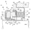
- FIG. 1 is a schematic cross-sectional view showing a use state of a mechanical seal according to an embodiment of the present invention.
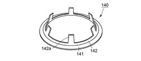
- FIG. 2 is a perspective view of the stopper according to the embodiment of the present invention.
- FIG. 1 is a schematic cross-sectional view showing a use state of a mechanical seal according to an embodiment of the present invention.
- the mechanical seal which concerns on a present Example is a rotationally symmetrical shape except for a part of member, and in FIG. 1, sectional drawing which cut
- FIG. 2 is a perspective view of the stopper according to the embodiment of the present invention.
- the direction in which the central axis of the mechanical seal (corresponding to the central axis of the rotating shaft) extends is referred to as the “axial direction”.
- the mechanical seal 10 serves to seal an annular gap between the rotating shaft 500 and the housing 600 having the shaft hole of the rotating shaft 500. As shown in FIG. 1, the annular gap between the rotating shaft 500 and the housing 600 is sealed by the mechanical seal 10, and the left region and the right region in the figure are separated. In the present embodiment, the fluid to be sealed is sealed in the left region in the figure, and the right side in the figure is exposed to the atmosphere. As a result, the left side in the figure is a high pressure, and accordingly, it is referred to as a high pressure side (H) and the right side is referred to as a low pressure side (L).
- H high pressure side
- L low pressure side
- the mechanical seal 10 includes a rotary ring unit 100 provided for the rotary shaft 500 and a fixed ring unit 200 provided for the housing 600.
- the rotating shaft 500 rotates
- the rotating ring unit 100 rotates together with the rotating shaft 500, while the stationary ring unit 200 is kept stationary.
- the rotary ring unit 100 includes a metal sleeve 120 fixed to the rotary shaft 500, and a rotary ring 110 that is prevented from rotating in the axial direction with respect to the sleeve 120 while being prevented from rotating.
- the rotating ring 110 is made of a hard material such as Sic, carbon, or metal.
- the rotary ring unit 100 moves the elastic ring (for example, rubber) gasket 130 that seals the gap between the sleeve 120 and the rotary ring 110 and the low pressure side (L) of the rotary ring 110.
- a restricting metal stopper 140 is also provided.
- the sleeve 120 includes a substantially cylindrical portion 121, an outward flange portion 122 that extends radially outward from an end of the substantially cylindrical portion 121 on the high pressure side (H), and a low pressure side (L ) And the locking projection 123 extending toward the center.
- the substantially cylindrical portion 121 includes a small diameter portion 121a, a large diameter portion 121b having a larger diameter than the small diameter portion 121a, and a connecting portion 121c that connects the small diameter portion 121a and the large diameter portion 121b.
- the small diameter portion 121a is fixed to the outer peripheral surface of the rotating shaft 500 by fitting.
- the large diameter part 121b is provided in the side in which the rotating ring 110 is provided rather than the small diameter part 121a.
- the connecting portion 121c is configured by a tapered portion whose diameter increases from the small diameter portion 121a toward the large diameter portion 121b.
- the rotating ring 110 is configured by a substantially cylindrical member.
- a locked groove 111 extending in the axial direction is formed on the outer peripheral surface side of the rotating ring 110.
- the locking projection 123 in the sleeve 120 is locked in the groove 111. Thereby, the rotation of the rotating ring 110 with respect to the sleeve 120 is prevented.
- the gasket 130 includes a cylindrical tubular seal portion 131 and a flange-shaped seal portion 132.
- the cylindrical seal portion 131 seals a gap between the inner peripheral surface of the rotating ring 110 and the outer peripheral surface of the large-diameter portion 121b in the sleeve 120.
- the flange-shaped seal portion 132 seals a gap between the end surface on the high-pressure side (H) of the rotating ring 110 and the outward flange portion 122 in the sleeve 120.
- the stopper 140 includes a plate-shaped annular portion 141 and an inclined portion 142 that extends in a tapered shape so as to reduce the diameter from the position of the radially inner end of the annular portion 141.
- the stopper 140 is press-fitted into the sleeve 120 and is fixed to the sleeve 120 by welding.
- the annular portion 141 in the stopper 140 is provided so as to face the low pressure side (L) end surface (the end surface on the side where the fixed ring 210 is provided) of the rotating ring 110.
- the inclined portion 142 is configured to extend from the position of the radially inner end of the annular portion 141 toward the radially inner side while being separated from the rotating ring 110.
- the inclined portion 142 and the sleeve 120 are fixed by the welded portion Y. Further, the inclined portion 142 has a plurality of protruding portions 142a provided at intervals. The plurality of projecting portions 142a are fixed to the sleeve 120 by the welded portions Y, respectively. More specifically, the plurality of protruding portions 142 a are fixed to the connecting portion 121 c in the sleeve 120.
- the fixed ring unit 200 includes a fixed ring 210 that is slidable with respect to the end surface of the rotating ring 110.
- the stationary ring 210 is made of a hard material such as Sic, carbon, or metal.
- the stationary ring 210 is provided with an annular projecting portion 211 that projects toward the rotating ring 110. When the rotating shaft 500 rotates, the tip surface of the projecting portion 211 slides with the end surface of the rotating ring 110 on the fixed ring 210 side.
- the fixed ring unit 200 is a metal case 220 that houses the fixed ring 210, and the elastic ring that positions the fixed ring 210 with respect to the case 220 and seals a gap between the case 220 and the fixed ring 210.
- a body gasket 230 is provided.
- the case 220 has a small-diameter portion 221, a large-diameter portion 222 having a diameter larger than that of the small-diameter portion 221, and a connecting portion 223 that connects the small-diameter portion 221 and the large-diameter portion 222. It is a member.
- a stationary ring 210 is accommodated inside the case 220.
- the gasket 230 includes a cylindrical seal portion 231 that seals a gap between the outer peripheral surface of the fixed ring 210 and the inner peripheral surface of the large-diameter portion 222 of the case 220, and a low-pressure side (L) of the fixed ring 210. It is comprised from the flange-shaped seal part 232 which seals the clearance gap between the end surface and the connection part 223 of case 220.
- FIG. 1 is comprised from the flange-shaped seal part 232 which seals the clearance gap between the end surface and the connection part 223 of case 220.
- the stationary ring unit 200 includes a metal cartridge 240 for forming the mechanical seal 10 into a cartridge.
- the cartridge 240 includes a cylindrical portion 241 fitted and fixed to the inner peripheral surface of the shaft hole of the housing 600, an outward flange portion 242 provided at an end portion on the high pressure side (H) of the cylindrical portion 241, and a cylindrical portion 241. And an inward flange portion 243 provided at the end of the low pressure side (L).
- the cartridge 240 is press-fitted into the shaft hole of the housing 600 until the outward flange portion 242 hits the end surface of the housing 600, whereby the mechanical seal 10 can be positioned with respect to the housing 600.
- the sleeve 120 and the cartridge 240 are not detached by bending the distal end of the small diameter portion 121a of the sleeve 120 toward the radially outer side. It becomes like this. Thereby, the mechanical seal 10 is made into a cartridge and can be handled as one component.
- the fixed ring unit 200 includes a metal bellows 250 as a pressing member that presses the fixed ring 210 toward the rotating ring 110.
- One end portion 251 of the bellows 250 is fixed to the connecting portion 223 of the case 220 by welding, and the other end portion 252 is fixed to the inward flange portion 243 of the cartridge 240 by welding.
- the bellows 250 is in a compressed state. Accordingly, the case 220 is pressed toward the high pressure side (H) by the spring force of the bellows 250. Therefore, the fixed ring 210 is pressed toward the rotating ring 110 by the bellows 250 through the case 220 and the gasket 230.
- the bellows 250 according to the present embodiment also has a function as a seal that separates the outer peripheral surface side and the inner peripheral surface side through the bellows 250.
- the stopper 140 includes an annular portion 141 and an inclined portion 142, and a configuration in which the inclined portion 142 and the sleeve 120 are fixed by the welded portion Y is employed.
- the inclined portion 142 has a plurality of protruding portions 142a provided at intervals, and the plurality of protruding portions 142a are fixed to the sleeve 120 by welded portions Y, respectively. Therefore, when the stopper 140 is press-fitted into the sleeve 120, it is possible to suppress the press-fitting load from becoming too large. Thereby, it can suppress that the stopper 140 strikes against the rotating ring 110 with a strong force. Therefore, the rotating ring 110 can be prevented from being broken or broken, and the rotating ring 110 can be prevented from being inclined.
- the flange-shaped seal portion 132 in the gasket 130 is sandwiched between the outward flange portion 122 of the sleeve 120 and the rotary ring 110.
- the stopper 140 restricts the movement of the gasket 130 together with the rotating ring 110. Therefore, the gasket 130 does not come out of the sleeve 120.
- the pressing member in the present invention is not limited to the bellows, and includes, for example, a spring.
Abstract
Priority Applications (4)
| Application Number | Priority Date | Filing Date | Title |
|---|---|---|---|
| JP2019517618A JP7046928B2 (ja) | 2017-05-12 | 2018-05-08 | メカニカルシール |
| CN201880030400.3A CN110603395B (zh) | 2017-05-12 | 2018-05-08 | 机械密封 |
| EP18798669.0A EP3623669B1 (fr) | 2017-05-12 | 2018-05-08 | Joint mécanique |
| US16/612,748 US11187326B2 (en) | 2017-05-12 | 2018-05-08 | Mechanical seal |
Applications Claiming Priority (2)
| Application Number | Priority Date | Filing Date | Title |
|---|---|---|---|
| JP2017-095986 | 2017-05-12 | ||
| JP2017095986 | 2017-05-12 |
Publications (1)
| Publication Number | Publication Date |
|---|---|
| WO2018207746A1 true WO2018207746A1 (fr) | 2018-11-15 |
Family
ID=64104718
Family Applications (1)
| Application Number | Title | Priority Date | Filing Date |
|---|---|---|---|
| PCT/JP2018/017688 WO2018207746A1 (fr) | 2017-05-12 | 2018-05-08 | Joint mécanique |
Country Status (5)
| Country | Link |
|---|---|
| US (1) | US11187326B2 (fr) |
| EP (1) | EP3623669B1 (fr) |
| JP (1) | JP7046928B2 (fr) |
| CN (1) | CN110603395B (fr) |
| WO (1) | WO2018207746A1 (fr) |
Families Citing this family (3)
| Publication number | Priority date | Publication date | Assignee | Title |
|---|---|---|---|---|
| CN110621924B (zh) * | 2017-05-12 | 2022-07-15 | 伊格尔工业股份有限公司 | 机械密封 |
| US11655721B2 (en) | 2020-10-29 | 2023-05-23 | Borgwarner Inc. | Turbocharger including a sealing assembly |
| CA3201318A1 (fr) * | 2021-02-12 | 2022-08-18 | Philip ROCKENBACH | Ensemble joint d'arbre hybride pour arbres mobiles |
Citations (4)
| Publication number | Priority date | Publication date | Assignee | Title |
|---|---|---|---|---|
| JPH07229566A (ja) * | 1993-12-20 | 1995-08-29 | John Crane Inc | シールリング設計の改良 |
| JPH11351407A (ja) * | 1998-06-09 | 1999-12-24 | Eagle Ind Co Ltd | 軸封装置 |
| JP2000074226A (ja) | 1998-08-27 | 2000-03-14 | Eagle Ind Co Ltd | メカニカルシール |
| WO2014054745A1 (fr) | 2012-10-04 | 2014-04-10 | イーグル工業株式会社 | Joint d'étanchéité mécanique |
Family Cites Families (21)
| Publication number | Priority date | Publication date | Assignee | Title |
|---|---|---|---|---|
| US4212475A (en) * | 1979-01-15 | 1980-07-15 | Crane Packing Co. | Self aligning spiral groove face seal |
| JPS58118375A (ja) | 1982-01-05 | 1983-07-14 | Arai Pump Mfg Co Ltd | メカニカルシ−ル |
| CH677266A5 (fr) * | 1986-10-28 | 1991-04-30 | Pacific Wietz Gmbh & Co Kg | |
| US5368314A (en) * | 1986-10-28 | 1994-11-29 | Pacific Wietz Gmbh & Co. Kg | Contactless pressurizing-gas shaft seal |
| GB8906901D0 (en) * | 1989-03-28 | 1989-05-10 | Crane John Uk Ltd | Mechanical face seals |
| JPH0756345B2 (ja) * | 1990-07-09 | 1995-06-14 | 株式会社荏原製作所 | 非接触端面シール |
| US5224714A (en) * | 1990-07-18 | 1993-07-06 | Ebara Corporation | Noncontacting face seal |
| US5533739A (en) * | 1992-06-10 | 1996-07-09 | Durametallic Corporation | Non-contacting seal with centering spring mounted in dovetailed grooved |
| DE19637813C2 (de) * | 1996-09-17 | 2001-12-06 | Freudenberg Carl Fa | Gleitringdichtung |
| JP3650954B2 (ja) * | 1998-09-18 | 2005-05-25 | イーグル工業株式会社 | 高速用非接触型メカニカルシール |
| EP1039184A1 (fr) * | 1999-03-22 | 2000-09-27 | Dresser Rand S.A | Joint d'étanchéité d'arbre |
| JP5271858B2 (ja) * | 2009-09-29 | 2013-08-21 | アイシン精機株式会社 | メカニカルシール及び液体ポンプ |
| US20120163904A1 (en) | 2010-12-23 | 2012-06-28 | Caterpillar Inc. | Seal assembly for pin joint |
| DE102011122477A1 (de) * | 2011-12-21 | 2013-06-27 | Kaco Gmbh + Co. Kg | Gleitringdichtung |
| WO2015108107A1 (fr) * | 2014-01-17 | 2015-07-23 | イーグル工業株式会社 | Joint mécanique |
| CN106471296B (zh) * | 2014-09-20 | 2018-12-28 | 伊格尔工业股份有限公司 | 滑动部件 |
| JP6479831B2 (ja) | 2014-09-24 | 2019-03-06 | イーグル工業株式会社 | メカニカルシール |
| CN205089979U (zh) | 2015-10-26 | 2016-03-16 | 玄兆丰 | 一种机械密封结构 |
| CN105333153B (zh) | 2015-12-01 | 2017-02-01 | 李富立 | 一种磁力轴密封装置及其加工方法 |
| CN205331037U (zh) | 2015-12-31 | 2016-06-22 | 中国电建集团上海能源装备有限公司 | 一种新型多级给水泵的油封装置 |
| CN106246922A (zh) | 2016-08-25 | 2016-12-21 | 浙江南元泵业有限公司 | 卧式泵用机械密封 |
-
2018
- 2018-05-08 CN CN201880030400.3A patent/CN110603395B/zh active Active
- 2018-05-08 US US16/612,748 patent/US11187326B2/en active Active
- 2018-05-08 EP EP18798669.0A patent/EP3623669B1/fr active Active
- 2018-05-08 WO PCT/JP2018/017688 patent/WO2018207746A1/fr active Application Filing
- 2018-05-08 JP JP2019517618A patent/JP7046928B2/ja active Active
Patent Citations (4)
| Publication number | Priority date | Publication date | Assignee | Title |
|---|---|---|---|---|
| JPH07229566A (ja) * | 1993-12-20 | 1995-08-29 | John Crane Inc | シールリング設計の改良 |
| JPH11351407A (ja) * | 1998-06-09 | 1999-12-24 | Eagle Ind Co Ltd | 軸封装置 |
| JP2000074226A (ja) | 1998-08-27 | 2000-03-14 | Eagle Ind Co Ltd | メカニカルシール |
| WO2014054745A1 (fr) | 2012-10-04 | 2014-04-10 | イーグル工業株式会社 | Joint d'étanchéité mécanique |
Non-Patent Citations (1)
| Title |
|---|
| See also references of EP3623669A4 |
Also Published As
| Publication number | Publication date |
|---|---|
| CN110603395A (zh) | 2019-12-20 |
| US11187326B2 (en) | 2021-11-30 |
| EP3623669A4 (fr) | 2021-01-20 |
| CN110603395B (zh) | 2021-04-30 |
| JP7046928B2 (ja) | 2022-04-04 |
| EP3623669A1 (fr) | 2020-03-18 |
| US20200200275A1 (en) | 2020-06-25 |
| EP3623669B1 (fr) | 2022-11-30 |
| JPWO2018207746A1 (ja) | 2020-03-12 |
Similar Documents
| Publication | Publication Date | Title |
|---|---|---|
| WO2018207746A1 (fr) | Joint mécanique | |
| JP4555096B2 (ja) | 保持部材、軸及びスナップリングの組付構造 | |
| US9644745B2 (en) | Mechanical seal | |
| JP5547354B1 (ja) | 密封装置 | |
| JP6496922B2 (ja) | 密封装置 | |
| JP2018096457A5 (fr) | ||
| WO2014030742A1 (fr) | Dispositif de scellement hermétique | |
| WO2018037918A1 (fr) | Dispositif d'étanchéité | |
| JPWO2012032678A1 (ja) | 軸封装置 | |
| JPWO2014030413A1 (ja) | 密封装置 | |
| JP5914682B2 (ja) | 密封装置 | |
| JP6994746B2 (ja) | ガスケット及び密封構造 | |
| JP2007132498A (ja) | 炭酸ガスシール用密封装置 | |
| JP2015059601A (ja) | 軸封装置 | |
| WO2018074395A1 (fr) | Dispositif d'étanchéité | |
| WO2018207747A1 (fr) | Joint mécanique | |
| JP2008025788A (ja) | 密封装置 | |
| WO2021215295A1 (fr) | Structure de montage de joint d'étanchéité | |
| EP4357645A1 (fr) | Dispositif d'étanchéité | |
| JP7118782B2 (ja) | 密封装置 | |
| JP3210688U (ja) | メカニカルシール | |
| JP2020070893A (ja) | バックアップリング及び密封構造 | |
| JP2018066398A (ja) | 密封装置 | |
| JP2018066397A (ja) | 密封装置 | |
| JP2009174552A (ja) | クラッチレリーズ軸受およびこれを備えるクラッチレリーズ軸受装置 |
Legal Events
| Date | Code | Title | Description |
|---|---|---|---|
| 121 | Ep: the epo has been informed by wipo that ep was designated in this application |
Ref document number: 18798669 Country of ref document: EP Kind code of ref document: A1 |
|
| ENP | Entry into the national phase |
Ref document number: 2019517618 Country of ref document: JP Kind code of ref document: A |
|
| NENP | Non-entry into the national phase |
Ref country code: DE |
|
| WWE | Wipo information: entry into national phase |
Ref document number: 2018798669 Country of ref document: EP |
|
| ENP | Entry into the national phase |
Ref document number: 2018798669 Country of ref document: EP Effective date: 20191212 |