WO2018207746A1 - Mechanical seal - Google Patents
Mechanical seal Download PDFInfo
- Publication number
- WO2018207746A1 WO2018207746A1 PCT/JP2018/017688 JP2018017688W WO2018207746A1 WO 2018207746 A1 WO2018207746 A1 WO 2018207746A1 JP 2018017688 W JP2018017688 W JP 2018017688W WO 2018207746 A1 WO2018207746 A1 WO 2018207746A1
- Authority
- WO
- WIPO (PCT)
- Prior art keywords
- sleeve
- rotating ring
- ring
- rotating
- fixed
- Prior art date
Links
Images
Classifications
-
- F—MECHANICAL ENGINEERING; LIGHTING; HEATING; WEAPONS; BLASTING
- F16—ENGINEERING ELEMENTS AND UNITS; GENERAL MEASURES FOR PRODUCING AND MAINTAINING EFFECTIVE FUNCTIONING OF MACHINES OR INSTALLATIONS; THERMAL INSULATION IN GENERAL
- F16J—PISTONS; CYLINDERS; SEALINGS
- F16J15/00—Sealings
- F16J15/16—Sealings between relatively-moving surfaces
- F16J15/34—Sealings between relatively-moving surfaces with slip-ring pressed against a more or less radial face on one member
- F16J15/3464—Mounting of the seal
- F16J15/3472—Means for centering or aligning the contacting faces
-
- F—MECHANICAL ENGINEERING; LIGHTING; HEATING; WEAPONS; BLASTING
- F16—ENGINEERING ELEMENTS AND UNITS; GENERAL MEASURES FOR PRODUCING AND MAINTAINING EFFECTIVE FUNCTIONING OF MACHINES OR INSTALLATIONS; THERMAL INSULATION IN GENERAL
- F16J—PISTONS; CYLINDERS; SEALINGS
- F16J15/00—Sealings
- F16J15/16—Sealings between relatively-moving surfaces
- F16J15/34—Sealings between relatively-moving surfaces with slip-ring pressed against a more or less radial face on one member
- F16J15/3464—Mounting of the seal
- F16J15/348—Pre-assembled seals, e.g. cartridge seals
-
- F—MECHANICAL ENGINEERING; LIGHTING; HEATING; WEAPONS; BLASTING
- F16—ENGINEERING ELEMENTS AND UNITS; GENERAL MEASURES FOR PRODUCING AND MAINTAINING EFFECTIVE FUNCTIONING OF MACHINES OR INSTALLATIONS; THERMAL INSULATION IN GENERAL
- F16J—PISTONS; CYLINDERS; SEALINGS
- F16J15/00—Sealings
- F16J15/16—Sealings between relatively-moving surfaces
- F16J15/34—Sealings between relatively-moving surfaces with slip-ring pressed against a more or less radial face on one member
- F16J15/36—Sealings between relatively-moving surfaces with slip-ring pressed against a more or less radial face on one member connected by a diaphragm or bellow to the other member
- F16J15/363—Sealings between relatively-moving surfaces with slip-ring pressed against a more or less radial face on one member connected by a diaphragm or bellow to the other member the diaphragm or bellow being made of metal
Definitions
- the present invention relates to a mechanical seal that seals an annular gap between a rotating shaft and a housing.
- the mechanical seal is equipped with a rotating ring that rotates with the rotating shaft.
- the rotating ring is prevented from rotating while being restrained from moving in the axial direction by the pressing force of the gasket and the pressing force received from the pressing member that presses the stationary ring.
- the rotating ring is particularly positioned in the radial direction by, for example, an elastic gasket fitted and fixed to a sleeve fixed to the rotating shaft.
- the rotating ring may be inclined and the sealing performance may be deteriorated.
- the gasket may come out of the sleeve.
- An object of the present invention is to provide a mechanical seal capable of positioning a rotating ring more reliably.
- the present invention employs the following means in order to solve the above problems.
- the mechanical seal of the present invention is A mechanical seal that seals an annular gap between a rotating shaft and a housing having a shaft hole through which the rotating shaft is inserted, A rotating ring unit provided for the rotating shaft; A stationary ring unit provided for the housing;
- the rotating ring unit is A sleeve fixed to the rotating shaft; A rotating ring that is prevented from rotating while being restrained from moving in the axial direction relative to the sleeve;
- the stationary ring unit is A stationary ring provided slidably with respect to an end face of the rotating ring; A pressing member that presses the stationary ring toward the rotating ring; With The sleeve is provided with a stopper for restricting movement of the rotating ring in a direction in which the fixed ring is provided.
- the stopper since the stopper is provided, it is possible to restrict the rotation ring from moving in the direction in which the fixed ring is provided.
- the stopper is An annular portion provided to face an end surface of the rotating ring on the side where the stationary ring is provided; From the position of the radially inner end of the annular portion, an inclined portion extending radially inward while leaving the rotating ring, With The inclined portion and the sleeve may be fixed by a welded portion.
- the inclined portion has a plurality of protruding portions provided at intervals, The plurality of protrusions may be fixed to the sleeve by welds.
- the sleeve is A small diameter portion fixed to the outer peripheral surface of the rotating shaft; A large-diameter portion provided on the side where the rotating ring is provided rather than the small-diameter portion, and having a larger diameter than the small-diameter portion; A tapered connecting portion connecting the small diameter portion and the large diameter portion; Have The inclined part in the stopper may be fixed to the connecting part.
- the inclined portion of the stopper can be more reliably brought into contact with the connecting portion of the sleeve, and the occurrence of poor welding can be suppressed.
- the sleeve has an outward flange portion at an end portion of the large diameter portion opposite to the small diameter portion
- the rotating ring unit is A cylindrical seal portion that seals a gap between the inner peripheral surface of the rotating ring and the outer peripheral surface of the large-diameter portion of the sleeve, and between the end surface of the rotating ring and the outward flange portion of the sleeve It is good to provide the gasket made from an elastic body which has a flange-shaped seal part which seals these gaps.
- the rotating ring can be positioned more reliably.
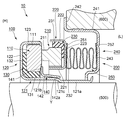
- FIG. 1 is a schematic cross-sectional view showing a use state of a mechanical seal according to an embodiment of the present invention.
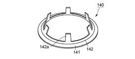
- FIG. 2 is a perspective view of the stopper according to the embodiment of the present invention.
- FIG. 1 is a schematic cross-sectional view showing a use state of a mechanical seal according to an embodiment of the present invention.
- the mechanical seal which concerns on a present Example is a rotationally symmetrical shape except for a part of member, and in FIG. 1, sectional drawing which cut
- FIG. 2 is a perspective view of the stopper according to the embodiment of the present invention.
- the direction in which the central axis of the mechanical seal (corresponding to the central axis of the rotating shaft) extends is referred to as the “axial direction”.
- the mechanical seal 10 serves to seal an annular gap between the rotating shaft 500 and the housing 600 having the shaft hole of the rotating shaft 500. As shown in FIG. 1, the annular gap between the rotating shaft 500 and the housing 600 is sealed by the mechanical seal 10, and the left region and the right region in the figure are separated. In the present embodiment, the fluid to be sealed is sealed in the left region in the figure, and the right side in the figure is exposed to the atmosphere. As a result, the left side in the figure is a high pressure, and accordingly, it is referred to as a high pressure side (H) and the right side is referred to as a low pressure side (L).
- H high pressure side
- L low pressure side
- the mechanical seal 10 includes a rotary ring unit 100 provided for the rotary shaft 500 and a fixed ring unit 200 provided for the housing 600.
- the rotating shaft 500 rotates
- the rotating ring unit 100 rotates together with the rotating shaft 500, while the stationary ring unit 200 is kept stationary.
- the rotary ring unit 100 includes a metal sleeve 120 fixed to the rotary shaft 500, and a rotary ring 110 that is prevented from rotating in the axial direction with respect to the sleeve 120 while being prevented from rotating.
- the rotating ring 110 is made of a hard material such as Sic, carbon, or metal.
- the rotary ring unit 100 moves the elastic ring (for example, rubber) gasket 130 that seals the gap between the sleeve 120 and the rotary ring 110 and the low pressure side (L) of the rotary ring 110.
- a restricting metal stopper 140 is also provided.
- the sleeve 120 includes a substantially cylindrical portion 121, an outward flange portion 122 that extends radially outward from an end of the substantially cylindrical portion 121 on the high pressure side (H), and a low pressure side (L ) And the locking projection 123 extending toward the center.
- the substantially cylindrical portion 121 includes a small diameter portion 121a, a large diameter portion 121b having a larger diameter than the small diameter portion 121a, and a connecting portion 121c that connects the small diameter portion 121a and the large diameter portion 121b.
- the small diameter portion 121a is fixed to the outer peripheral surface of the rotating shaft 500 by fitting.
- the large diameter part 121b is provided in the side in which the rotating ring 110 is provided rather than the small diameter part 121a.
- the connecting portion 121c is configured by a tapered portion whose diameter increases from the small diameter portion 121a toward the large diameter portion 121b.
- the rotating ring 110 is configured by a substantially cylindrical member.
- a locked groove 111 extending in the axial direction is formed on the outer peripheral surface side of the rotating ring 110.
- the locking projection 123 in the sleeve 120 is locked in the groove 111. Thereby, the rotation of the rotating ring 110 with respect to the sleeve 120 is prevented.
- the gasket 130 includes a cylindrical tubular seal portion 131 and a flange-shaped seal portion 132.
- the cylindrical seal portion 131 seals a gap between the inner peripheral surface of the rotating ring 110 and the outer peripheral surface of the large-diameter portion 121b in the sleeve 120.
- the flange-shaped seal portion 132 seals a gap between the end surface on the high-pressure side (H) of the rotating ring 110 and the outward flange portion 122 in the sleeve 120.
- the stopper 140 includes a plate-shaped annular portion 141 and an inclined portion 142 that extends in a tapered shape so as to reduce the diameter from the position of the radially inner end of the annular portion 141.
- the stopper 140 is press-fitted into the sleeve 120 and is fixed to the sleeve 120 by welding.
- the annular portion 141 in the stopper 140 is provided so as to face the low pressure side (L) end surface (the end surface on the side where the fixed ring 210 is provided) of the rotating ring 110.
- the inclined portion 142 is configured to extend from the position of the radially inner end of the annular portion 141 toward the radially inner side while being separated from the rotating ring 110.
- the inclined portion 142 and the sleeve 120 are fixed by the welded portion Y. Further, the inclined portion 142 has a plurality of protruding portions 142a provided at intervals. The plurality of projecting portions 142a are fixed to the sleeve 120 by the welded portions Y, respectively. More specifically, the plurality of protruding portions 142 a are fixed to the connecting portion 121 c in the sleeve 120.
- the fixed ring unit 200 includes a fixed ring 210 that is slidable with respect to the end surface of the rotating ring 110.
- the stationary ring 210 is made of a hard material such as Sic, carbon, or metal.
- the stationary ring 210 is provided with an annular projecting portion 211 that projects toward the rotating ring 110. When the rotating shaft 500 rotates, the tip surface of the projecting portion 211 slides with the end surface of the rotating ring 110 on the fixed ring 210 side.
- the fixed ring unit 200 is a metal case 220 that houses the fixed ring 210, and the elastic ring that positions the fixed ring 210 with respect to the case 220 and seals a gap between the case 220 and the fixed ring 210.
- a body gasket 230 is provided.
- the case 220 has a small-diameter portion 221, a large-diameter portion 222 having a diameter larger than that of the small-diameter portion 221, and a connecting portion 223 that connects the small-diameter portion 221 and the large-diameter portion 222. It is a member.
- a stationary ring 210 is accommodated inside the case 220.
- the gasket 230 includes a cylindrical seal portion 231 that seals a gap between the outer peripheral surface of the fixed ring 210 and the inner peripheral surface of the large-diameter portion 222 of the case 220, and a low-pressure side (L) of the fixed ring 210. It is comprised from the flange-shaped seal part 232 which seals the clearance gap between the end surface and the connection part 223 of case 220.
- FIG. 1 is comprised from the flange-shaped seal part 232 which seals the clearance gap between the end surface and the connection part 223 of case 220.
- the stationary ring unit 200 includes a metal cartridge 240 for forming the mechanical seal 10 into a cartridge.
- the cartridge 240 includes a cylindrical portion 241 fitted and fixed to the inner peripheral surface of the shaft hole of the housing 600, an outward flange portion 242 provided at an end portion on the high pressure side (H) of the cylindrical portion 241, and a cylindrical portion 241. And an inward flange portion 243 provided at the end of the low pressure side (L).
- the cartridge 240 is press-fitted into the shaft hole of the housing 600 until the outward flange portion 242 hits the end surface of the housing 600, whereby the mechanical seal 10 can be positioned with respect to the housing 600.
- the sleeve 120 and the cartridge 240 are not detached by bending the distal end of the small diameter portion 121a of the sleeve 120 toward the radially outer side. It becomes like this. Thereby, the mechanical seal 10 is made into a cartridge and can be handled as one component.
- the fixed ring unit 200 includes a metal bellows 250 as a pressing member that presses the fixed ring 210 toward the rotating ring 110.
- One end portion 251 of the bellows 250 is fixed to the connecting portion 223 of the case 220 by welding, and the other end portion 252 is fixed to the inward flange portion 243 of the cartridge 240 by welding.
- the bellows 250 is in a compressed state. Accordingly, the case 220 is pressed toward the high pressure side (H) by the spring force of the bellows 250. Therefore, the fixed ring 210 is pressed toward the rotating ring 110 by the bellows 250 through the case 220 and the gasket 230.
- the bellows 250 according to the present embodiment also has a function as a seal that separates the outer peripheral surface side and the inner peripheral surface side through the bellows 250.
- the stopper 140 includes an annular portion 141 and an inclined portion 142, and a configuration in which the inclined portion 142 and the sleeve 120 are fixed by the welded portion Y is employed.
- the inclined portion 142 has a plurality of protruding portions 142a provided at intervals, and the plurality of protruding portions 142a are fixed to the sleeve 120 by welded portions Y, respectively. Therefore, when the stopper 140 is press-fitted into the sleeve 120, it is possible to suppress the press-fitting load from becoming too large. Thereby, it can suppress that the stopper 140 strikes against the rotating ring 110 with a strong force. Therefore, the rotating ring 110 can be prevented from being broken or broken, and the rotating ring 110 can be prevented from being inclined.
- the flange-shaped seal portion 132 in the gasket 130 is sandwiched between the outward flange portion 122 of the sleeve 120 and the rotary ring 110.
- the stopper 140 restricts the movement of the gasket 130 together with the rotating ring 110. Therefore, the gasket 130 does not come out of the sleeve 120.
- the pressing member in the present invention is not limited to the bellows, and includes, for example, a spring.
Abstract
Description
回転軸と、該回転軸が挿通される軸孔を有するハウジングとの間の環状隙間を封止するメカニカルシールであって、
前記回転軸に対して設けられる回転環ユニットと、
前記ハウジングに対して設けられる固定環ユニットと、
を備えるメカニカルシールにおいて、
前記回転環ユニットは、
前記回転軸に固定されるスリーブと、
前記スリーブに対して軸線方向への移動が抑制されつつ廻り止めがなされている回転環と、
を備えており、
前記固定環ユニットは、
前記回転環の端面に対して摺動自在に設けられる固定環と、
前記固定環を前記回転環に向けて押圧する押圧部材と、
を備えると共に、
前記スリーブには、前記固定環が設けられている方向への前記回転環の移動を規制するストッパが設けられていることを特徴とする。 That is, the mechanical seal of the present invention is
A mechanical seal that seals an annular gap between a rotating shaft and a housing having a shaft hole through which the rotating shaft is inserted,
A rotating ring unit provided for the rotating shaft;
A stationary ring unit provided for the housing;
In a mechanical seal comprising:
The rotating ring unit is
A sleeve fixed to the rotating shaft;
A rotating ring that is prevented from rotating while being restrained from moving in the axial direction relative to the sleeve;
With
The stationary ring unit is
A stationary ring provided slidably with respect to an end face of the rotating ring;
A pressing member that presses the stationary ring toward the rotating ring;
With
The sleeve is provided with a stopper for restricting movement of the rotating ring in a direction in which the fixed ring is provided.
前記回転環における前記固定環が設けられている側の端面に対向するように設けられる環状部と、
前記環状部における径方向内側の端部の位置から、前記回転環から離れつつ径方向内側に向かって伸びる傾斜部と、
を備え、
前記傾斜部と前記スリーブとが溶接部により固定されているとよい。 The stopper is
An annular portion provided to face an end surface of the rotating ring on the side where the stationary ring is provided;
From the position of the radially inner end of the annular portion, an inclined portion extending radially inward while leaving the rotating ring,
With
The inclined portion and the sleeve may be fixed by a welded portion.
これら複数の突出部が、それぞれ溶接部によって前記スリーブに固定されているとよい。 The inclined portion has a plurality of protruding portions provided at intervals,
The plurality of protrusions may be fixed to the sleeve by welds.
前記回転軸の外周面に固定される小径部と、
前記小径部よりも前記回転環が設けられている側に設けられ、かつ前記小径部よりも径の大きな大径部と、
前記小径部と大径部とを繋ぐテーパ状の繋ぎ部と、
を有しており、
前記ストッパにおける傾斜部は、前記繋ぎ部に固定されているとよい。 The sleeve is
A small diameter portion fixed to the outer peripheral surface of the rotating shaft;
A large-diameter portion provided on the side where the rotating ring is provided rather than the small-diameter portion, and having a larger diameter than the small-diameter portion;
A tapered connecting portion connecting the small diameter portion and the large diameter portion;
Have
The inclined part in the stopper may be fixed to the connecting part.
前記回転環ユニットは、
前記回転環の内周面と前記スリーブにおける前記大径部の外周面との間の隙間を封止する筒状シール部と、前記回転環の端面と前記スリーブにおける前記外向きフランジ部との間の隙間を封止するフランジ状シール部と、を有する弾性体製のガスケットを備えるとよい。 The sleeve has an outward flange portion at an end portion of the large diameter portion opposite to the small diameter portion, and
The rotating ring unit is
A cylindrical seal portion that seals a gap between the inner peripheral surface of the rotating ring and the outer peripheral surface of the large-diameter portion of the sleeve, and between the end surface of the rotating ring and the outward flange portion of the sleeve It is good to provide the gasket made from an elastic body which has a flange-shaped seal part which seals these gaps.
図1及び図2を参照して、本発明の実施例に係るメカニカルシールについて説明する。図1は本発明の実施例に係るメカニカルシールの使用状態を示す模式的断面図である。なお、本実施例に係るメカニカルシールは、一部の部材を除き、回転対称形状であり、図1においては、メカニカルシールの中心軸線を含む面でメカニカルシールを切断した断面図を示している。図2は本発明の実施例に係るストッパの斜視図である。なお、以下の説明において、メカニカルシールの中心軸線(回転軸の中心軸線に一致する)が伸びる方向を「軸線方向」と称する。 (Example)
With reference to FIG.1 and FIG.2, the mechanical seal which concerns on the Example of this invention is demonstrated. FIG. 1 is a schematic cross-sectional view showing a use state of a mechanical seal according to an embodiment of the present invention. In addition, the mechanical seal which concerns on a present Example is a rotationally symmetrical shape except for a part of member, and in FIG. 1, sectional drawing which cut | disconnected the mechanical seal in the surface containing the center axis line of a mechanical seal is shown. FIG. 2 is a perspective view of the stopper according to the embodiment of the present invention. In the following description, the direction in which the central axis of the mechanical seal (corresponding to the central axis of the rotating shaft) extends is referred to as the “axial direction”.
本実施例に係るメカニカルシール10の全体構成について説明する。メカニカルシール10は、回転軸500と、回転軸500の軸孔を有するハウジング600との間の環状隙間を密封する役割を担っている。図1に示すように、メカニカルシール10によって、回転軸500とハウジング600との間の環状隙間が封止されて、図中左側の領域と右側の領域とが隔てられる。本実施例においては、図中左側の領域に密封対象流体が封止され、図中右側は大気に曝される。これにより、図中左側は高圧となるため、適宜、高圧側(H)と称し、右側を低圧側(L)と称する。 <Mechanical seal>
The overall configuration of the
回転環ユニット100は、回転軸500に固定される金属製のスリーブ120と、スリーブ120に対して軸線方向への移動が抑制されつつ廻り止めがなされている回転環110とを備えている。回転環110は、Sic,カーボンまたは金属などの硬質材料で構成されている。また、回転環ユニット100は、スリーブ120と回転環110との間の隙間を封止する弾性体製(例えば、ゴム製)のガスケット130と、回転環110の低圧側(L)への移動を規制する金属製のストッパ140も設けられている。 <Rotating ring unit>
The
固定環ユニット200は、回転環110の端面に対して摺動自在に設けられる固定環210を備えている。固定環210は、Sic,カーボンまたは金属などの硬質材料で構成されている。また、固定環210には、回転環110に向かって突出する環状の突出部211が設けられている。回転軸500が回転すると、この突出部211の先端面と回転環110における固定環210側の端面とが摺動する。 <Fixed ring unit>
The fixed
以上のように構成された本実施例に係るメカニカルシール10によれば、ストッパ140が設けられているため、固定環210が設けられている方向に、回転環110が移動してしまうことを規制することができる。つまり、回転環110における高圧側(H)の端面とスリーブ120における外向きフランジ部122との間には、密封対象流体が存在している。従って、高圧側(H)の密封対象流体の流体圧力が高い場合、回転環110には低圧側(L)に向かう力が作用する。これにより、ストッパ140がないと、回転環110が傾いて密封性が低下してしまうおそれがある。本実施例の場合には、上記の通りストッパ140が設けられているため、回転環110の移動が規制され、回転環110の傾きなどを制限することができる。従って、安定した密封性を得ることができる。 <Excellent points of mechanical seal according to this embodiment>
According to the
上記実施例においては、押圧部材がベローズの場合を例にして説明したが、本発明における押圧部材はベローズに限定されることはなく、例えば、スプリングの場合も含まれる。 (Other)
In the above embodiment, the case where the pressing member is a bellows has been described as an example. However, the pressing member in the present invention is not limited to the bellows, and includes, for example, a spring.
100 回転環ユニット
110 回転環
111 溝
120 スリーブ
121 略円筒部
121a 小径部
121b 大径部
121c 繋ぎ部
122 外向きフランジ部
123 係止突起部
130 ガスケット
131 筒状シール部
132 フランジ状シール部
140 ストッパ
141 環状部
142 傾斜部
142a 突出部
200 固定環ユニット
210 固定環
211 突出部
220 ケース
221 小径部
222 大径部
223 連結部
230 ガスケット
231 円筒状シール部
232 フランジ状シール部
240 カートリッジ
241 円筒部
242 外向きフランジ部
243 内向きフランジ部
250 ベローズ
251 一端部
252 他端部
500 回転軸
600 ハウジング
Y 溶接部 DESCRIPTION OF
Claims (5)
- 回転軸と、該回転軸が挿通される軸孔を有するハウジングとの間の環状隙間を封止するメカニカルシールであって、
前記回転軸に対して設けられる回転環ユニットと、
前記ハウジングに対して設けられる固定環ユニットと、
を備えるメカニカルシールにおいて、
前記回転環ユニットは、
前記回転軸に固定されるスリーブと、
前記スリーブに対して軸線方向への移動が抑制されつつ廻り止めがなされている回転環と、
を備えており、
前記固定環ユニットは、
前記回転環の端面に対して摺動自在に設けられる固定環と、
前記固定環を前記回転環に向けて押圧する押圧部材と、
を備えると共に、
前記スリーブには、前記固定環が設けられている方向への前記回転環の移動を規制するストッパが設けられていることを特徴とするメカニカルシール。 A mechanical seal that seals an annular gap between a rotating shaft and a housing having a shaft hole through which the rotating shaft is inserted,
A rotating ring unit provided for the rotating shaft;
A stationary ring unit provided for the housing;
In a mechanical seal comprising:
The rotating ring unit is
A sleeve fixed to the rotating shaft;
A rotating ring that is prevented from rotating while being restrained from moving in the axial direction relative to the sleeve;
With
The stationary ring unit is
A stationary ring provided slidably with respect to an end face of the rotating ring;
A pressing member that presses the stationary ring toward the rotating ring;
With
The mechanical seal according to claim 1, wherein the sleeve is provided with a stopper for restricting movement of the rotating ring in a direction in which the fixed ring is provided. - 前記ストッパは、
前記回転環における前記固定環が設けられている側の端面に対向するように設けられる環状部と、
前記環状部における径方向内側の端部の位置から、前記回転環から離れつつ径方向内側に向かって伸びる傾斜部と、
を備え、
前記傾斜部と前記スリーブとが溶接部により固定されていることを特徴とする請求項1に記載のメカニカルシール。 The stopper is
An annular portion provided to face an end surface of the rotating ring on the side where the stationary ring is provided;
From the position of the radially inner end of the annular portion, an inclined portion extending radially inward while leaving the rotating ring,
With
The mechanical seal according to claim 1, wherein the inclined portion and the sleeve are fixed by a welded portion. - 前記傾斜部は、それぞれ間隔を空けて設けられる複数の突出部を有しており、
これら複数の突出部が、それぞれ溶接部によって前記スリーブに固定されていることを特徴とする請求項2に記載のメカニカルシール。 The inclined portion has a plurality of protruding portions provided at intervals,
The mechanical seal according to claim 2, wherein the plurality of protrusions are respectively fixed to the sleeve by welds. - 前記スリーブは、
前記回転軸の外周面に固定される小径部と、
前記小径部よりも前記回転環が設けられている側に設けられ、かつ前記小径部よりも径の大きな大径部と、
前記小径部と大径部とを繋ぐテーパ状の繋ぎ部と、
を有しており、
前記ストッパにおける傾斜部は、前記繋ぎ部に固定されていることを特徴とする請求項2または3に記載のメカニカルシール。 The sleeve is
A small diameter portion fixed to the outer peripheral surface of the rotating shaft;
A large-diameter portion provided on the side where the rotating ring is provided rather than the small-diameter portion, and having a larger diameter than the small-diameter portion;
A tapered connecting portion connecting the small diameter portion and the large diameter portion;
Have
The mechanical seal according to claim 2 or 3, wherein the inclined portion of the stopper is fixed to the joint portion. - 前記スリーブは、前記大径部における前記小径部とは反対側の端部に外向きフランジ部を有すると共に、
前記回転環ユニットは、
前記回転環の内周面と前記スリーブにおける前記大径部の外周面との間の隙間を封止する筒状シール部と、前記回転環の端面と前記スリーブにおける前記外向きフランジ部との間の隙間を封止するフランジ状シール部と、を有する弾性体製のガスケットを備えることを特徴とする請求項4に記載のメカニカルシール。 The sleeve has an outward flange portion at an end portion of the large diameter portion opposite to the small diameter portion, and
The rotating ring unit is
A cylindrical seal portion that seals a gap between the inner peripheral surface of the rotating ring and the outer peripheral surface of the large-diameter portion of the sleeve, and between the end surface of the rotating ring and the outward flange portion of the sleeve The mechanical seal according to claim 4, further comprising an elastic gasket having a flange-like seal portion that seals the gap.
Priority Applications (4)
| Application Number | Priority Date | Filing Date | Title |
|---|---|---|---|
| CN201880030400.3A CN110603395B (en) | 2017-05-12 | 2018-05-08 | Mechanical seal |
| JP2019517618A JP7046928B2 (en) | 2017-05-12 | 2018-05-08 | mechanical seal |
| EP18798669.0A EP3623669B1 (en) | 2017-05-12 | 2018-05-08 | Mechanical seal |
| US16/612,748 US11187326B2 (en) | 2017-05-12 | 2018-05-08 | Mechanical seal |
Applications Claiming Priority (2)
| Application Number | Priority Date | Filing Date | Title |
|---|---|---|---|
| JP2017-095986 | 2017-05-12 | ||
| JP2017095986 | 2017-05-12 |
Publications (1)
| Publication Number | Publication Date |
|---|---|
| WO2018207746A1 true WO2018207746A1 (en) | 2018-11-15 |
Family
ID=64104718
Family Applications (1)
| Application Number | Title | Priority Date | Filing Date |
|---|---|---|---|
| PCT/JP2018/017688 WO2018207746A1 (en) | 2017-05-12 | 2018-05-08 | Mechanical seal |
Country Status (5)
| Country | Link |
|---|---|
| US (1) | US11187326B2 (en) |
| EP (1) | EP3623669B1 (en) |
| JP (1) | JP7046928B2 (en) |
| CN (1) | CN110603395B (en) |
| WO (1) | WO2018207746A1 (en) |
Families Citing this family (3)
| Publication number | Priority date | Publication date | Assignee | Title |
|---|---|---|---|---|
| CN110621924B (en) * | 2017-05-12 | 2022-07-15 | 伊格尔工业股份有限公司 | Mechanical seal |
| US11655721B2 (en) | 2020-10-29 | 2023-05-23 | Borgwarner Inc. | Turbocharger including a sealing assembly |
| WO2022173892A1 (en) * | 2021-02-12 | 2022-08-18 | Parker-Hannifin Corporation | Hybrid shaft seal assembly for movable shafts |
Citations (4)
| Publication number | Priority date | Publication date | Assignee | Title |
|---|---|---|---|---|
| JPH07229566A (en) * | 1993-12-20 | 1995-08-29 | John Crane Inc | Improvement of seal ring design |
| JPH11351407A (en) * | 1998-06-09 | 1999-12-24 | Eagle Ind Co Ltd | Shaft seal device |
| JP2000074226A (en) | 1998-08-27 | 2000-03-14 | Eagle Ind Co Ltd | Mechanical seal |
| WO2014054745A1 (en) | 2012-10-04 | 2014-04-10 | イーグル工業株式会社 | Mechanical seal |
Family Cites Families (21)
| Publication number | Priority date | Publication date | Assignee | Title |
|---|---|---|---|---|
| US4212475A (en) * | 1979-01-15 | 1980-07-15 | Crane Packing Co. | Self aligning spiral groove face seal |
| JPS58118375A (en) | 1982-01-05 | 1983-07-14 | Arai Pump Mfg Co Ltd | Mechanical seal |
| CH677266A5 (en) * | 1986-10-28 | 1991-04-30 | Pacific Wietz Gmbh & Co Kg | |
| US5368314A (en) * | 1986-10-28 | 1994-11-29 | Pacific Wietz Gmbh & Co. Kg | Contactless pressurizing-gas shaft seal |
| GB8906901D0 (en) | 1989-03-28 | 1989-05-10 | Crane John Uk Ltd | Mechanical face seals |
| JPH0756345B2 (en) * | 1990-07-09 | 1995-06-14 | 株式会社荏原製作所 | Non-contact end face seal |
| US5224714A (en) * | 1990-07-18 | 1993-07-06 | Ebara Corporation | Noncontacting face seal |
| US5533739A (en) * | 1992-06-10 | 1996-07-09 | Durametallic Corporation | Non-contacting seal with centering spring mounted in dovetailed grooved |
| DE19637813C2 (en) * | 1996-09-17 | 2001-12-06 | Freudenberg Carl Fa | Mechanical seal |
| JP3650954B2 (en) * | 1998-09-18 | 2005-05-25 | イーグル工業株式会社 | Non-contact mechanical seal for high speed |
| EP1039184A1 (en) * | 1999-03-22 | 2000-09-27 | Dresser Rand S.A | Shaft seal |
| JP5271858B2 (en) * | 2009-09-29 | 2013-08-21 | アイシン精機株式会社 | Mechanical seal and liquid pump |
| US20120163904A1 (en) | 2010-12-23 | 2012-06-28 | Caterpillar Inc. | Seal assembly for pin joint |
| DE102011122477A1 (en) | 2011-12-21 | 2013-06-27 | Kaco Gmbh + Co. Kg | Mechanical seal |
| EP3096048B1 (en) * | 2014-01-17 | 2020-05-06 | Eagle Industry Co., Ltd. | Mechanical seal |
| CN106471296B (en) * | 2014-09-20 | 2018-12-28 | 伊格尔工业股份有限公司 | Slide unit |
| AU2015322889B2 (en) | 2014-09-24 | 2018-10-04 | Eagle Industry Co., Ltd. | Mechanical seal |
| CN205089979U (en) | 2015-10-26 | 2016-03-16 | 玄兆丰 | Mechanical seal structure |
| CN105333153B (en) | 2015-12-01 | 2017-02-01 | 李富立 | Magnetic force shaft sealing device and processing method thereof |
| CN205331037U (en) | 2015-12-31 | 2016-06-22 | 中国电建集团上海能源装备有限公司 | Novel oil blanket of multistage water -feeding pump device |
| CN106246922A (en) | 2016-08-25 | 2016-12-21 | 浙江南元泵业有限公司 | horizontal mechanical seal for pump |
-
2018
- 2018-05-08 CN CN201880030400.3A patent/CN110603395B/en active Active
- 2018-05-08 EP EP18798669.0A patent/EP3623669B1/en active Active
- 2018-05-08 US US16/612,748 patent/US11187326B2/en active Active
- 2018-05-08 WO PCT/JP2018/017688 patent/WO2018207746A1/en active Application Filing
- 2018-05-08 JP JP2019517618A patent/JP7046928B2/en active Active
Patent Citations (4)
| Publication number | Priority date | Publication date | Assignee | Title |
|---|---|---|---|---|
| JPH07229566A (en) * | 1993-12-20 | 1995-08-29 | John Crane Inc | Improvement of seal ring design |
| JPH11351407A (en) * | 1998-06-09 | 1999-12-24 | Eagle Ind Co Ltd | Shaft seal device |
| JP2000074226A (en) | 1998-08-27 | 2000-03-14 | Eagle Ind Co Ltd | Mechanical seal |
| WO2014054745A1 (en) | 2012-10-04 | 2014-04-10 | イーグル工業株式会社 | Mechanical seal |
Non-Patent Citations (1)
| Title |
|---|
| See also references of EP3623669A4 |
Also Published As
| Publication number | Publication date |
|---|---|
| CN110603395B (en) | 2021-04-30 |
| JP7046928B2 (en) | 2022-04-04 |
| JPWO2018207746A1 (en) | 2020-03-12 |
| EP3623669B1 (en) | 2022-11-30 |
| EP3623669A4 (en) | 2021-01-20 |
| US11187326B2 (en) | 2021-11-30 |
| EP3623669A1 (en) | 2020-03-18 |
| US20200200275A1 (en) | 2020-06-25 |
| CN110603395A (en) | 2019-12-20 |
Similar Documents
| Publication | Publication Date | Title |
|---|---|---|
| WO2018207746A1 (en) | Mechanical seal | |
| JP4555096B2 (en) | Assembly structure of holding member, shaft and snap ring | |
| US9644745B2 (en) | Mechanical seal | |
| JP5547354B1 (en) | Sealing device | |
| JP6496922B2 (en) | Sealing device | |
| JP2018096457A5 (en) | ||
| WO2014030742A1 (en) | Sealing device | |
| WO2018037918A1 (en) | Sealing device | |
| JPWO2012032678A1 (en) | Shaft seal device | |
| JPWO2014030413A1 (en) | Sealing device | |
| JP5914682B2 (en) | Sealing device | |
| JP6994746B2 (en) | Gasket and sealing structure | |
| JP2007132498A (en) | Sealing device for carbon dioxide seal | |
| JP2015059601A (en) | Shaft sealing device | |
| WO2018074395A1 (en) | Sealing device | |
| WO2018207747A1 (en) | Mechanical seal | |
| JP2008025788A (en) | Sealing device | |
| WO2021215295A1 (en) | Gasket mounting structure | |
| EP4357645A1 (en) | Sealing device | |
| JP7118782B2 (en) | sealing device | |
| JP3210688U (en) | mechanical seal | |
| JP2020070893A (en) | Backup ring and seal structure | |
| JP2018066398A (en) | Sealing device | |
| JP2018066397A (en) | Sealing device | |
| JP2009174552A (en) | Clutch release bearing, and clutch release bearing device with the same |
Legal Events
| Date | Code | Title | Description |
|---|---|---|---|
| 121 | Ep: the epo has been informed by wipo that ep was designated in this application |
Ref document number: 18798669 Country of ref document: EP Kind code of ref document: A1 |
|
| ENP | Entry into the national phase |
Ref document number: 2019517618 Country of ref document: JP Kind code of ref document: A |
|
| NENP | Non-entry into the national phase |
Ref country code: DE |
|
| WWE | Wipo information: entry into national phase |
Ref document number: 2018798669 Country of ref document: EP |
|
| ENP | Entry into the national phase |
Ref document number: 2018798669 Country of ref document: EP Effective date: 20191212 |