WO2018207492A1 - ボイラ水処理装置および処理方法 - Google Patents
ボイラ水処理装置および処理方法 Download PDFInfo
- Publication number
- WO2018207492A1 WO2018207492A1 PCT/JP2018/013228 JP2018013228W WO2018207492A1 WO 2018207492 A1 WO2018207492 A1 WO 2018207492A1 JP 2018013228 W JP2018013228 W JP 2018013228W WO 2018207492 A1 WO2018207492 A1 WO 2018207492A1
- Authority
- WO
- WIPO (PCT)
- Prior art keywords
- boiler
- water
- pure water
- toc
- supply line
- Prior art date
- Legal status (The legal status is an assumption and is not a legal conclusion. Google has not performed a legal analysis and makes no representation as to the accuracy of the status listed.)
- Ceased
Links
Images


Classifications
-
- C—CHEMISTRY; METALLURGY
- C02—TREATMENT OF WATER, WASTE WATER, SEWAGE, OR SLUDGE
- C02F—TREATMENT OF WATER, WASTE WATER, SEWAGE, OR SLUDGE
- C02F1/00—Treatment of water, waste water, or sewage
- C02F1/30—Treatment of water, waste water, or sewage by irradiation
- C02F1/32—Treatment of water, waste water, or sewage by irradiation with ultraviolet light
-
- C—CHEMISTRY; METALLURGY
- C02—TREATMENT OF WATER, WASTE WATER, SEWAGE, OR SLUDGE
- C02F—TREATMENT OF WATER, WASTE WATER, SEWAGE, OR SLUDGE
- C02F1/00—Treatment of water, waste water, or sewage
- C02F1/42—Treatment of water, waste water, or sewage by ion-exchange
-
- C—CHEMISTRY; METALLURGY
- C02—TREATMENT OF WATER, WASTE WATER, SEWAGE, OR SLUDGE
- C02F—TREATMENT OF WATER, WASTE WATER, SEWAGE, OR SLUDGE
- C02F1/00—Treatment of water, waste water, or sewage
- C02F1/44—Treatment of water, waste water, or sewage by dialysis, osmosis or reverse osmosis
-
- F—MECHANICAL ENGINEERING; LIGHTING; HEATING; WEAPONS; BLASTING
- F22—STEAM GENERATION
- F22B—METHODS OF STEAM GENERATION; STEAM BOILERS
- F22B37/00—Component parts or details of steam boilers
- F22B37/02—Component parts or details of steam boilers applicable to more than one kind or type of steam boiler
- F22B37/48—Devices or arrangements for removing water, minerals or sludge from boilers ; Arrangement of cleaning apparatus in boilers; Combinations thereof with boilers
- F22B37/52—Washing-out devices
-
- F—MECHANICAL ENGINEERING; LIGHTING; HEATING; WEAPONS; BLASTING
- F22—STEAM GENERATION
- F22D—PREHEATING, OR ACCUMULATING PREHEATED, FEED-WATER FOR STEAM GENERATION; FEED-WATER SUPPLY FOR STEAM GENERATION; CONTROLLING WATER LEVEL FOR STEAM GENERATION; AUXILIARY DEVICES FOR PROMOTING WATER CIRCULATION WITHIN STEAM BOILERS
- F22D11/00—Feed-water supply not provided for in other main groups
-
- Y—GENERAL TAGGING OF NEW TECHNOLOGICAL DEVELOPMENTS; GENERAL TAGGING OF CROSS-SECTIONAL TECHNOLOGIES SPANNING OVER SEVERAL SECTIONS OF THE IPC; TECHNICAL SUBJECTS COVERED BY FORMER USPC CROSS-REFERENCE ART COLLECTIONS [XRACs] AND DIGESTS
- Y02—TECHNOLOGIES OR APPLICATIONS FOR MITIGATION OR ADAPTATION AGAINST CLIMATE CHANGE
- Y02A—TECHNOLOGIES FOR ADAPTATION TO CLIMATE CHANGE
- Y02A20/00—Water conservation; Efficient water supply; Efficient water use
- Y02A20/124—Water desalination
- Y02A20/131—Reverse-osmosis
Definitions
- the present invention relates to an apparatus and method for treating boiler water of power generation equipment such as commercial thermal power, IPP power generation equipment or industrial thermal power generation equipment.
- IPP power generation independent power generation business
- pure water is produced from industrial water or the like by pretreatment (such as agglomeration solid-liquid separation and desalination treatment), and steam is generated from the pure water using a high pressure boiler to generate power.
- pretreatment such as agglomeration solid-liquid separation and desalination treatment
- steam is generated from the pure water using a high pressure boiler to generate power.
- boiler blow water is collected, desalted, and reused as pure water for power generation (Patent Documents 1 to 3).
- the boiler water quality is managed in the power generation facility.
- the electrical conductivity of boiler water after being treated with an ion exchange resin is managed.
- raw water contains TOC more than expected (for example, TOC 200 ppb or more), or when organic substances are excessively eluted from ion-exchange resin in pre-treatment pure water production, the electrical conductivity of boiler water exceeds the control value. Resulting in.
- An object of the present invention is to provide a boiler water treatment apparatus and a treatment method capable of stably supplying high-quality pure water to a boiler even when the TOC of raw water or pretreatment water is high in concentration.
- the boiler water treatment device of the present invention is a boiler water treatment device having a pretreatment device for producing pure water by treating raw water, and a pure water supply line for supplying pure water from the pretreatment device to the boiler.
- the take-out unit is provided in a pure water tank of a pure water supply line.
- the TOC removing unit includes an RO device or a UV oxidation device and an ion exchange device.
- the boiler water treatment apparatus includes a measuring unit for measuring the TOC concentration of pure water in the pure water take-out unit or the upstream side of the pure water supply line, and a measured value of the measuring unit is a predetermined value.
- the TOC removal unit starts the TOC removal, or the pure water supply amount control unit increases the pure water supply amount to the TOC removal unit.
- a boiler water treatment apparatus includes condensate demineralization means for desalinating boiler blow water discharged from the boiler after exhaust steam from the boiler is condensed, and boiler blow water from the boiler A boiler blow water introduction line to be introduced into the condensate demineralization means, and a condensate for returning the condensate demineralized water desalted by the condensate demineralization means to the take-out section or a pure water supply line upstream of the extraction section. And a desalted water return line.
- the boiler water treatment apparatus includes an RO device as the TOC removing unit, and a heat exchanger for exchanging heat between the RO concentrated water and the boiler blow water of the RO device is provided in the boiler blow water introduction line. Prepare.
- the boiler water treatment method of the present invention is a boiler water treatment method in which raw water is treated with a pretreatment device to produce pure water, and pure water from the pretreatment device is supplied to the boiler via a pure water supply line. , Removing a part of the pure water from the pure water supply line from the take-out part, and removing the TOC by the TOC removing means, and returning the treated water to the take-out part or the pure water supply line on the upstream side thereof. It is a feature.
- the TOC removing unit includes an RO device or a UV oxidation device and an ion exchange device.
- the TOC concentration of pure water in the pure water supply line on the upstream side with respect to the take-out part is measured, and the TOC removal is performed when the measured value is a predetermined value or more.
- the TOC removal by the means is started, or the amount of pure water supplied to the TOC removal means is increased.
- the boiler blow water discharged from the boiler after the exhaust steam from the boiler is condensed is desalted by the condensate demineralization means, and dehydrated by the condensate demineralization means.
- the salt-treated condensate demineralized water is returned to the extraction section or the pure water supply line upstream of the extraction section.
- the TOC removing unit includes an RO device, and heat exchange is performed between the RO concentrated water of the RO device and the boiler blow water supplied to the condensate demineralization unit. Then, the boiler blow water is cooled.
- the TOC removal means is not provided in the pure water supply line (main line) for supplying pure water from the pretreatment device to the boiler, but the TOC removal line (offline) branched from the pure water supply line. Removal means are provided. Therefore, the TOC removing unit can be controlled separately from the pure water supply control in the pure water supply line (main line).
- the TOC removal operation when the TOC load of raw water is low, the TOC removal operation can be temporarily suspended. Further, even when the pure water supply line is in a pure water supply operation, the maintenance of the TOC removing means can be performed.
- the RO concentrated water in the TOC removal line is used as cooling water for boiler blow water.
- FIG. 1 is a flowchart of a boiler water treatment apparatus according to an embodiment of the present invention.
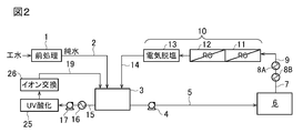
- FIG. 2 is a flowchart of a boiler water treatment apparatus according to another embodiment.
- FIG. 3 is a flowchart of the boiler water treatment apparatus according to the comparative example.
- FIG. 1 is a flowchart of the boiler water treatment apparatus according to the first embodiment.
- Industrial water industrial water
- pure water tank 3 corresponding to a takeout portion
- Pure water in the pure water tank 3 is supplied to a boiler of a power generator 6 such as an IPP power generator via a pipe 5 having a pump 4.
- the pure water supply line has a pipe 2, a pure water tank 3, a pump 4 and a pipe 5.
- Boiler blow water generated in the boiler of the power generation device 6 is introduced into the condensate demineralizer 10 through the introduction line having the pipe 7, the first heat exchanger 8B, the cooling means 8A, and the pipe 9, and is desalted.
- the condensate desalination apparatus 10 includes reverse osmosis membrane separation apparatuses (RO apparatuses) 11 and 12 arranged in a plurality of stages (two stages in this embodiment), and an electric desalination apparatus 13. Have.
- the boiler blow water is desalted by RO treatment and electric desalination treatment to become pure water, and is returned to the pure water tank 3 via the pipe 14.
- a TOC removal line is provided in order to take out a part of pure water in the pure water tank 3 and perform TOC removal treatment and desalination treatment.
- Pure water in the pure water tank 3 is supplied to the RO device 18 via the pipe 15, the second heat exchanger 16, and the pump 17, and RO permeated water is returned to the pure water tank 3 via the pipe 19.
- the RO concentrated water is supplied to the first heat exchanger 8B via the pipe 20, and after heat exchange with the boiler blow water, the pre-treatment device 1 or upstream of the raw water pipe or the raw water tank is supplied via the pipe 21. Returned or discharged out of the system.
- the second heat exchanger 16 heats pure water supplied from the pure water tank 3 to the RO device 18.
- the first heat exchanger 8B cools and lowers the temperature of the boiler blow water sent to the condensate demineralizer 10.
- the concentrated water from the RO device 18 is passed through the first heat exchanger 8B to the low temperature fluid side.
- the pump 17 is operated when necessary, and the pure water in the pure water tank 3 is subjected to RO treatment by the RO device 18, whereby the quality of pure water in the pure water tank 3 is predetermined. Can be kept in range.
- the RO treatment efficiency can be increased by heating the pure water supplied to the RO device 18 with the second heat exchanger 16.
- the water temperature in the pure water tank 3 increases.
- the pipe 15 is connected to the pure water tank 3 as a take-out portion, but the pipe 15 may be connected to the pipe 5 on the downstream side of the pure water tank 3. In this case, the branch point becomes the takeout part.
- FIG. 2 is a flowchart of the boiler water treatment apparatus according to the second embodiment.
- a TOC removing device for maintaining the quality of pure water in the pure water tank 3 a UV (ultraviolet) oxidation device 25 and an ion exchange device 26 are installed instead of the RO device 18 in FIG.
- the ion exchange resin is preferably an anion exchange resin or a mixed bed resin.
- UV oxidation apparatus e.g., a low-pressure UV oxidation apparatus
- the organic material by irradiating the (pure water from the pure water tank 3) the UV treated water and organic acids to CO 2.
- the organic acid, CO 2 and the like generated by the decomposition are removed by the ion exchange device 26 at the subsequent stage. Pure water having a low organic matter concentration that has passed through the ion exchange device 26 is returned from the pipe 19 to the pure water tank 3.
- the pipes 20 and 21 for supplying the RO concentrated water to the first heat exchanger 8B are not installed. Cooling water introduced from outside the system is passed through the first heat exchanger 8B on the low temperature fluid side.
- Boiler blow water from the boiler of the power generation device 6 is sent to the condensate demineralizer 10 through an introduction line having the pipe 7, the first heat exchanger 8B, the cooling means 8A, and the pipe 9.
- Other configurations are the same as those in FIG. 1, and the same reference numerals indicate the same parts.
- Pretreatment device 1 removes the raw water such as industrial water (city water, groundwater, etc.) after performing coagulation treatment, solid-liquid separation (precipitation separation, pressurized flotation separation, etc.) and two-layer filtration sequentially. Pure water is produced by performing a salt treatment (treatment with a cation exchange resin tower, a decarboxylation tower, an anion exchange resin tower, a mixed bed resin tower, an electric desalination apparatus, or the like).
- a salt treatment treatment with a cation exchange resin tower, a decarboxylation tower, an anion exchange resin tower, a mixed bed resin tower, an electric desalination apparatus, or the like.
- Pure water tank 3 In the pure water tank 3, pure water produced by the pretreatment is stored, and the water quality and the amount of water are adjusted.
- TOC removal means When the TOC concentration contained in raw water such as industrial water is high, it may be difficult to reduce the TOC concentration to a predetermined value or less (for example, less than 100 ppb) by pretreatment. When the TOC concentration is 100 ppb or more, there is a concern that a burden on the boiler becomes large and a failure may occur in the future.
- the water temperature varies depending on the season and climate (for example, 5 to 35 ° C). When the water temperature is 15 ° C. or less, the load on the power generation boiler increases and the amount of fuel used increases.
- the pure water collected from the pure water tank 3 constituting the pure water supply line is supplied to the RO device 18 so that the TOC of pure water in the pure water tank 3 is always maintained at a predetermined value or less (for example, 100 ppb or less).
- the TOC removal process is performed by the TOC removal means comprising the UV oxidation device 25 and the ion exchange device 26.
- the TOC removing means By using a physicochemical means as the TOC removing means, it is possible to prevent impurities from remaining in the treated water.
- the TOC removal means By installing the TOC removal means in the TOC removal line branched from the pure water supply line, for example, control and maintenance different from the pure water supply line are possible, such as being unaffected by the stoppage of water flow due to the membrane backwashing.
- the TOC removing means can be easily installed in an existing boiler water supply device by additional work.
- the TOC concentration measuring means and the pump 17 are interlocked, and when the measured value of the TOC concentration measuring means exceeds a predetermined value, the pump 17 is operated to supply water to the TOC removing means, and the TOC.
- a removal process may be performed.
- An on-off valve is provided in the pipe 15, and this on-off valve is interlocked with the TOC concentration measuring means to open the on-off valve when the measured value of the TOC concentration measuring means is a predetermined value or more and supply pure water to the TOC removing means. You may make it perform a TOC removal process.
- the pump 17 is stopped or the on-off valve is closed to stop the supply of pure water to the TOC removing means.
- the amount of pure water supplied to the TOC removing means may be controlled. For example, by interlocking the TOC concentration measuring means and the pump 17, when the measured value of the TOC concentration measuring means exceeds a predetermined value, the rotational speed of the pump 17 is increased to increase the amount of pure water supplied to the TOC removing means. The amount of pure water to be subjected to the TOC removal process may be increased.
- a flow rate adjusting valve is provided in the pipe 15, and this flow rate adjusting valve is linked to the TOC concentration measuring means.
- the opening of the flow adjusting valve is increased to remove the TOC.
- the amount of pure water supplied to the means may be increased to increase the amount of pure water subjected to the TOC removal process.
- the pure water supply amount to the TOC removing means is reduced by reducing the rotational speed of the pump 17 or reducing the opening of the flow rate adjusting valve.
- the required amount of pure water can be processed by the TOC removing means by controlling the presence or the amount of pure water supplied to the TOC removing means. Costs related to the TOC removal process can be reduced.
- the control of whether or not the pure water is supplied to the TOC removing means or the increase / decrease in the supply amount is performed by inputting the measured value of the TOC concentration of the TOC concentration measuring means and outputting a control signal to the pump or valve based on the measured value. It can be performed automatically by the control device.
- the power generation device 6 there are various types such as an IPP power generation device equipped with a high-pressure boiler.
- Boiler blow water discharge line to condensate demineralization means to condensate return line The boiler steam condensate is generally at a high temperature (for example, 70 to 97 ° C), and after being discharged from the boiler as boiler blow water, cooling means 8A (sealed) After cooling to about 20 to 40 ° C. by a cooling tower, a heat exchanger, etc., it is supplied to the condensate demineralizer 10.
- First heat exchanger 8B As shown in FIG. 1, when the RO device 18 is used as the TOC removing means, the RO concentrated water at a room temperature (5 to 35 ° C.) is discharged, so this RO concentrated water is provided in the first stage of the cooling means 8A. 1 Water is passed through the heat exchanger 8B to exchange heat with the boiler blow water, and the boiler blow water is precooled to about 50 to 70 ° C. Thereby, the load of the cooling means 8A provided in the front stage of the condensate demineralizer 10 is reduced.
- Second heat exchanger 16 When the water temperature of the pure water tank 3 is likely to drop to a predetermined value or lower (for example, 15 ° C. or lower), the water supplied from the TOC removing unit is heated by exchanging heat with hot water in the second heat exchanger 16. Thereby, it is possible to remove the TOC efficiently by the TOC removing means. If the water temperature of the pure water tank 3 is maintained at 20 to 35 ° C., for example, the burden on the high-pressure boiler of the IPP power generation facility can be reduced.
- a predetermined value or lower for example, 15 ° C. or lower
- the valve may be switched so as to supply hot water to the second heat exchanger 16 and the temperature may be controlled by this mechanism.
- the flow rate may be controlled so as to adjust the supply flow rate to the second heat exchanger 16 based on the measured water temperature.
- Example 1 Chiba Prefecture industrial water (TOC concentration 2 to 3 ppm; water temperature 10 ° C.) was treated by the boiler water treatment device shown in FIG. 1 and supplied to the boiler of the IPP power generation device 6, and boiler blow water was collected.
- the pretreatment apparatus 1 pure water was produced by performing agglomeration treatment, pressurized flotation separation, two-layer filtration, two-bed three-column ion exchange (cation exchange, decarboxylation, anion exchange). The main conditions are shown below and in Table 1. The results are shown in Table 1.
- Average supply amount of industrial water (average flow rate in pipe 2): 35 m 3 / hr Pure water tank 3 volume: 400m 3 Average amount of water supply to the IPP power generation boiler (average flow rate in the pipe 5): 35 m 3 / hr Boiler blow water average flow rate (average flow rate in pipe 7): 10 to 12 m 3 / hr RO device 18 average water supply amount (average flow rate in pipe 15): 34 m 3 / hr RO device 18 average permeate flow rate (average flow rate in pipe 19): 30 m 3 / hr 1st heat exchanger 8B feed water average flow rate: 10-12m 3 / hr Cooling means 8A water supply average flow rate: 10-12 m 3 / hr Second heat exchanger 16 average feed water flow rate: 34 m 3 / hr
- Example 2 The operation was performed under the same conditions as in Example 1 except that the boiler water treatment apparatus shown in FIG. The results are shown in Table 1.
- Example 3 In Example 1, the 2nd heat exchanger 16 was abbreviate
- FIG. The results are shown in Table 1.
- Example 4 In Example 1, the operation was performed under the same conditions as in Example 1 except that the pipes 20 and 21 and the first heat exchanger 8B were omitted and the boiler blow water was not preliminarily cooled with the RO concentrated water. The results are shown in Table 1.
- Example 1 In Example 1, the piping 15 for removing the TOC, the second heat exchanger 16, the pump 17, the RO device 18, the piping 19, the piping 20, 21 and the first heat exchanger 8B are omitted, and the flow of FIG. The operation was performed under the same conditions as in Example 1 except that. The results are shown in Table 1.
- the TOC concentration of boiler feed water is lower than that in Comparative Example 1, and the load on the boiler is reduced.
- the TOC removal rate in the same RO apparatus is higher in Examples 1 and 4 in which the TOC removal line was not preheated than in Example 3 in which the TOC removal line was not preliminarily performed.
- the load on the subsequent boiler is reduced.
- the load on the subsequent cooling means is reduced in the first to third embodiments in which the boiler blow water was not preliminarily cooled in the first to third embodiments.
Landscapes
- Engineering & Computer Science (AREA)
- Water Supply & Treatment (AREA)
- Organic Chemistry (AREA)
- Life Sciences & Earth Sciences (AREA)
- Chemical & Material Sciences (AREA)
- Environmental & Geological Engineering (AREA)
- Hydrology & Water Resources (AREA)
- Physics & Mathematics (AREA)
- Thermal Sciences (AREA)
- General Engineering & Computer Science (AREA)
- Mechanical Engineering (AREA)
- Toxicology (AREA)
- Health & Medical Sciences (AREA)
- Physical Water Treatments (AREA)
- Separation Using Semi-Permeable Membranes (AREA)
- Treatment Of Water By Ion Exchange (AREA)
Abstract
工水は、前処理装置1、純水タンク3を介して発電装置6のボイラへ供給される。ボイラブロー水は、復水脱塩装置10により脱塩され、純水タンク3に返送される。純水タンク3内の純水の一部がRO装置18へ供給され、RO透過水が純水タンク3に返送される。RO濃縮水は、配管20を介して第1熱交換器8Bへ送水される。
Description
本発明は、事業用火力、IPP発電設備或いは産業用火力発電設備等の発電設備のボイラ水を処理する装置及び方法に関する。
コンビナートにおいてIPP発電(独立系発電事業)の実施が広がっている。IPP等の発電設備では、工業用水等から前処理(凝集固液分離と脱塩処理など)により純水を製造し、この純水を用いて高圧ボイラにより蒸気を発生させて発電が行われる。発電設備では、ボイラブロー水を回収し、脱塩処理した後に発電用の純水として再利用する(特許文献1~3)。
発電施設内では、ボイラ水の水質を管理している。特に、腐食防止の為、イオン交換樹脂にて処理した後のボイラ水の電気伝導度を管理している。原水にTOCが想定以上に含まれていた場合(例えばTOC200ppb以上)、または前処理の純水製造におけるイオン交換樹脂から有機物が過度に溶出した場合は、ボイラ水の電気伝導度が管理値を超過してしまう。
平成14年版 ボイラー年鑑、「第9節 自家発電用ボイラにおける原水・補給水水質とボイラ水質への影響および対応策について」
本発明は、原水又は前処理水のTOCが高濃度の場合でも安定して高品質の純水をボイラに給水することができるボイラ水処理装置及び処理方法を提供することを目的とする。
本発明のボイラ水処理装置は、原水を処理して純水を製造する前処理装置と、該前処理装置からの純水をボイラへ供給する純水供給ラインとを有するボイラ水処理装置において、該純水供給ラインから純水の一部を取り出し部から取り出してTOC除去手段でTOC除去処理し、この処理水を該取り出し部又はそれよりも上流側の該純水供給ラインに戻すTOC除去ラインを備えたことを特徴とするものである。
本発明の一態様では、該取り出し部は、純水供給ラインの純水タンクに設けられる。
本発明の一態様では、前記TOC除去手段は、RO装置を有するか、又はUV酸化装置及びイオン交換装置を有する。
本発明の一態様のボイラ水処理装置は、前記純水の取り出し部又はそれよりも上流側の前記純水供給ラインの純水のTOC濃度の測定手段と、該測定手段の測定値が所定値以上のときに前記TOC除去手段によるTOC除去を開始するか、又はTOC除去手段への純水供給量を増加させる純水供給量制御手段を備える。
本発明の一態様のボイラ水処理装置は、前記ボイラからの排気蒸気が凝縮されて該ボイラから排出されたボイラブロー水を脱塩処理する復水脱塩手段と、該ボイラからのボイラブロー水を該復水脱塩手段に導入するボイラブロー水導入ラインと、該復水脱塩手段で脱塩処理された復水脱塩水を前記取り出し部又はそれよりも上流側の純水供給ラインに返送する復水脱塩水返送ラインとを備える。
本発明の一態様のボイラ水処理装置は、前記TOC除去手段としてRO装置を有しており、該RO装置のRO濃縮水とボイラブロー水とを熱交換させる熱交換器を前記ボイラブロー水導入ラインに備える。
本発明のボイラ水処理方法は、原水を前処理装置で処理して純水を製造し、該前処理装置からの純水を純水供給ラインを経由してボイラへ供給するボイラ水処理方法において、該純水供給ラインから純水の一部を取り出し部から取り出してTOC除去手段でTOC除去処理し、この処理水を該取り出し部又はそれよりも上流側の該純水供給ラインに戻すことを特徴とするものである。
本発明の一態様のボイラ水処理方法では、前記TOC除去手段は、RO装置を有するか、又はUV酸化装置及びイオン交換装置を有する。
本発明の一態様のボイラ水処理方法では、前記取り出し部又はそれよりも上流側の前記純水供給ラインの純水のTOC濃度を測定し、該測定値が所定値以上のときに前記TOC除去手段によるTOC除去を開始するか、又はTOC除去手段への純水供給量を増加させる。
本発明の一態様のボイラ水処理方法では、前記ボイラからの排気蒸気が凝縮されて該ボイラから排出されたボイラブロー水を復水脱塩手段で脱塩処理し、該復水脱塩手段で脱塩処理された復水脱塩水を前記取り出し部又はそれよりも上流側の純水供給ラインに返送する。
本発明の一態様のボイラ水処理方法では、前記TOC除去手段はRO装置を有しており、該RO装置のRO濃縮水と前記復水脱塩手段に供給されるボイラブロー水とを熱交換して、該ボイラブロー水を冷却する。
本発明では、前処理装置からの純水をボイラに供給する純水供給ライン(メインライン)にTOC除去手段を設けるのではなく、該純水供給ラインから分岐したTOC除去ライン(オフライン)にTOC除去手段を設けている。そのため、TOC除去手段を、純水供給ライン(メインライン)での純水供給制御とは別に制御することができる。
例えば、本発明では、原水のTOC負荷が低いときには、TOC除去運転を一時中断することができる。また、純水供給ラインが純水供給作動しているときでも、TOC除去手段のメンテナンスが可能である。
本発明の一態様では、ボイラブロー水の脱塩手段に由来する樹脂溶出物の影響を抑えることができる。
本発明の一態様では、TOC除去ラインのRO濃縮水がボイラブロー水の冷却水として使用される。
以下、図面を参照して実施の形態について説明する。
図1は、第1の実施の形態に係るボイラ水処理装置のフロー図である。原水としての工水(工業用水)は、前処理装置1で前処理されて純水となり、配管2を介して純水タンク3(取り出し部に相当)に導入される。純水タンク3内の純水は、ポンプ4を有する配管5を介してIPP発電装置などの発電装置6のボイラへ供給される。
この実施の形態では、純水供給ラインは、配管2、純水タンク3、ポンプ4及び配管5を有する。発電装置6のボイラで生じたボイラブロー水は、配管7、第1熱交換器8B、冷却手段8A及び配管9を有した導入ラインを介して復水脱塩装置10に導入され、脱塩処理される。
この実施の形態では、復水脱塩装置10は直列に複数段(この実施の形態では2段)配置された逆浸透膜分離装置(RO装置)11,12と、電気脱塩装置13とを有する。ボイラブロー水は、RO処理及び電気脱塩処理により脱塩処理されて純水となり、配管14を介して純水タンク3に返送される。
純水タンク3内の純水の一部を取り出してTOC除去処理及び脱塩処理するために、TOC除去ラインが設けられている。純水タンク3内の純水が配管15、第2熱交換器16、ポンプ17を介してRO装置18へ供給され、RO透過水が配管19を介して純水タンク3に返送される。RO濃縮水は、配管20を介して第1熱交換器8Bへ送水され、ボイラブロー水と熱交換した後、配管21を介して前処理装置1又はそれよりも上流側の原水配管や原水タンクへ返送されるか、又は系外へ排出される。
第2熱交換器16は、純水タンク3からRO装置18に供給される純水を加熱する。
第1熱交換器8Bは、復水脱塩装置10に送水されるボイラブロー水を冷却して降温させる。第1熱交換器8Bの低温流体側には、RO装置18からの濃縮水が通水される。
このボイラ水処理装置にあっては、ポンプ17を必要時に稼働させて、純水タンク3内の純水をRO装置18によってRO処理することにより、純水タンク3内の純水の水質を所定範囲に維持することができる。
RO装置18へ供給される純水を第2熱交換器16で加熱することにより、RO処理効率を高くすることができる。温度の高いRO透過水が純水タンク3に流入することにより、純水タンク3内の水温が高くなる。
図1では、配管15は取り出し部として純水タンク3に接続されているが、配管15は純水タンク3の下流側の配管5に接続されてもよい。この場合は分岐点が取り出し部となる。
図1において、第1熱交換器8Bを省略し、予備冷却を行わず冷却手段8Aのみでボイラブロー水を所定温度まで冷却することも可能である。
図2は、第2の実施の形態に係るボイラ水処理装置のフロー図である。純水タンク3内の純水の水質維持用のTOC除去装置として、図1におけるRO装置18の代わりにUV(紫外線)酸化装置25とイオン交換装置26とが設置されている。
イオン交換樹脂としては、アニオン交換樹脂又は混床樹脂が好ましい。UV酸化装置(例えば、低圧UV酸化装置)25では、UVを被処理水(純水タンク3からの純水)に照射して有機物を有機酸さらにはCO2まで分解する。分解により生じた有機酸、CO2等は、後段のイオン交換装置26で除去される。イオン交換装置26を通過した有機物濃度の低い純水が配管19から純水タンク3に返送される。
この実施の形態では、RO装置18は設けられていないので、RO濃縮水を第1熱交換器8Bへ供給するための配管20,21は設置されていない。第1熱交換器8Bの低温流体側には系外から導入した冷却水が通水される。
発電装置6のボイラからのボイラブロー水は、配管7、第1熱交換器8B、冷却手段8A及び配管9を有した導入ラインを介して復水脱塩装置10へ送水される。その他の構成は図1と同一であり、同一符号は同一部分を示している。
図2において、第1熱交換器8Bを省略し、予備冷却を行わず冷却手段8Aのみでボイラブロー水を所定温度まで冷却することも可能である。
図1,2は本発明の一例であり、本発明は図示以外の形態とされてもよい。
図1,2のボイラ水処理装置の構成機器の好適例、機能等について以下に説明する。
1) 前処理装置1
前処理装置1は、例えば、工業用水(市水、地下水など)等の原水に対して、凝集処理、固液分離(沈殿分離や加圧浮上分離など)、二層濾過を順次行った後に脱塩処理(カチオン交換樹脂塔、脱炭酸塔、アニオン交換樹脂塔、混床樹脂塔、電気脱塩装置などによる処理)を行うことにより、純水を製造する。
前処理装置1は、例えば、工業用水(市水、地下水など)等の原水に対して、凝集処理、固液分離(沈殿分離や加圧浮上分離など)、二層濾過を順次行った後に脱塩処理(カチオン交換樹脂塔、脱炭酸塔、アニオン交換樹脂塔、混床樹脂塔、電気脱塩装置などによる処理)を行うことにより、純水を製造する。
2) 純水タンク3
純水タンク3では、前処理により製造された純水が貯留され、水質や水量の調整が行われる。
純水タンク3では、前処理により製造された純水が貯留され、水質や水量の調整が行われる。
3) TOC除去手段
工業用水等の原水に含まれるTOC濃度が高い場合は、前処理によってTOC濃度を所定以下(例えば100ppb未満)まで低減することが困難となる場合がある。TOC濃度が100ppb以上になるとボイラへの負担が大きくなり将来的に故障が生じる懸念がある。また、季節や気候などにより水温が変動する(例えば5~35℃)。水温が15℃以下になると発電用ボイラへの負担が大きくなり燃料使用量が多くなる。
工業用水等の原水に含まれるTOC濃度が高い場合は、前処理によってTOC濃度を所定以下(例えば100ppb未満)まで低減することが困難となる場合がある。TOC濃度が100ppb以上になるとボイラへの負担が大きくなり将来的に故障が生じる懸念がある。また、季節や気候などにより水温が変動する(例えば5~35℃)。水温が15℃以下になると発電用ボイラへの負担が大きくなり燃料使用量が多くなる。
そのため、純水タンク3内の純水のTOCが常に所定値以下(例えば100ppb以下)に維持されるように、純水供給ラインを構成する純水タンク3から分取した純水をRO装置18、又はUV酸化装置25及びイオン交換装置26よりなるTOC除去手段でTOC除去処理を行う。
TOC除去手段として物理化学的手段を用いることにより、処理水に不純物が残留することを抑制できる。TOC除去手段を、純水供給ラインから分岐したTOC除去ラインに設置することにより、例えば膜逆洗に伴う通水停止に影響されないなど、純水供給ラインと異なる制御やメンテナンスが可能となる。TOC除去手段は既設のボイラ給水装置に、追加工事で容易に設置することができる。
TOC除去手段でTOC除去処理する純水の取り出し部(図1,2では純水タンク3)又はそれよりも上流側の純水供給ライン(図1,2では配管2)の純水のTOC濃度を測定するTOC濃度測定手段を設け、このTOC濃度測定手段の測定値が所定値以上のときに、TOC除去手段によるTOC除去処理を開始するようにしてもよい。
この場合、例えば、TOC濃度測定手段とポンプ17とを連動させて、TOC濃度測定手段の測定値が所定値以上になったら、ポンプ17を作動させて、TOC除去手段に水を供給してTOC除去処理するようにしてもよい。配管15に開閉弁を設け、この開閉弁をTOC濃度測定手段と連動させて、TOC濃度測定手段の測定値が所定値以上のときに開閉弁を開としてTOC除去手段に純水を供給してTOC除去処理するようにしてもよい。TOC濃度測定手段の測定値が所定値よりも低くなった場合には、ポンプ17を停止するか開閉弁を閉としてTOC除去手段への純水の供給を停止する。
TOC濃度測定手段の測定値に基づいて、TOC除去手段への純水の供給の有無を制御する他、TOC除去手段への純水の供給量を制御してもよい。例えば、TOC濃度測定手段とポンプ17とを連動させて、TOC濃度測定手段の測定値が所定値以上になったら、ポンプ17の回転数を上げて、TOC除去手段への純水供給量を増加させ、TOC除去処理する純水量を増やしてもよい。配管15に流量調整弁を設け、この流量調整弁をTOC濃度測定手段と連動させて、TOC濃度測定手段の測定値が所定値以上になったら、流量調整弁の開度を大きくしてTOC除去手段への純水供給量を増加させ、TOC除去処理する純水量を増やしてもよい。TOC濃度測定手段の測定値が所定値より低くなった場合には、ポンプ17の回転数を下げるか流量調整弁の開度を小さくしてTOC除去手段への純水供給量を少なくする。
TOC濃度測定手段の測定値に基づいて、TOC除去手段への純水の供給の有無や供給量を制御することにより、必要量の純水をTOC除去手段で処理することができ、純水のTOC除去処理に係るコストを低減することができる。
TOC除去手段への純水の供給の有無又は供給量の増減の制御は、TOC濃度測定手段のTOC濃度の測定値が入力され、この測定値に基づいてポンプ又は弁への制御信号を出力する制御装置により、自動制御で行うことができる。
4) 発電装置6としては、高圧ボイラを備えたIPP発電装置など各種のものがある。
5)ボイラブロー水排出ライン~復水脱塩手段~復水返送ライン
ボイラ蒸気の凝縮水は一般には高温であり(例えば70~97℃)、ボイラからボイラブロー水として排出された後に冷却手段8A(密閉冷却塔、熱交換器など)により20~40℃程度に冷却された後、復水脱塩装置10に供給される。
ボイラ蒸気の凝縮水は一般には高温であり(例えば70~97℃)、ボイラからボイラブロー水として排出された後に冷却手段8A(密閉冷却塔、熱交換器など)により20~40℃程度に冷却された後、復水脱塩装置10に供給される。
図1,2では、復水脱塩装置10として、直列2段RO処理→電気脱塩を例示しているが、脱塩処理できる物理化学的手段であれば特に限定されない。
6) 第1熱交換器8B
図1のように、TOC除去手段としてRO装置18を用いる場合、常温程度(5~35℃)のRO濃縮水が排出されるので、このRO濃縮水を冷却手段8Aの前段に設けられた第1熱交換器8Bに通水してボイラブロー水と熱交換してボイラブロー水を50~70℃程度に予備冷却する。これにより、復水脱塩装置10前段に設けられた冷却手段8Aの負荷を軽減する。
図1のように、TOC除去手段としてRO装置18を用いる場合、常温程度(5~35℃)のRO濃縮水が排出されるので、このRO濃縮水を冷却手段8Aの前段に設けられた第1熱交換器8Bに通水してボイラブロー水と熱交換してボイラブロー水を50~70℃程度に予備冷却する。これにより、復水脱塩装置10前段に設けられた冷却手段8Aの負荷を軽減する。
7) 第2熱交換器16
純水タンク3の水温が所定値以下(例えば15℃以下)に低下しやすい場合は、TOC除去手段の給水を第2熱交換器16にて温水と熱交換して加温する。これにより、TOC除去手段で効率的にTOC除去することが可能である。純水タンク3の水温が例えば20~35℃に維持されるようにすれば、IPP発電設備の高圧ボイラの負担を軽減することができる。
純水タンク3の水温が所定値以下(例えば15℃以下)に低下しやすい場合は、TOC除去手段の給水を第2熱交換器16にて温水と熱交換して加温する。これにより、TOC除去手段で効率的にTOC除去することが可能である。純水タンク3の水温が例えば20~35℃に維持されるようにすれば、IPP発電設備の高圧ボイラの負担を軽減することができる。
純水供給ライン(配管2、純水タンク3、配管5等)や、TOC除去ライン(配管15,19等)中の水温を測定し、測定値が所定値以下にまで低温になったときに、第2熱交換器16に温水を供給するように弁を切り替えて本機構による昇温を行うように制御してもよい。水温測定値に基づいて第2熱交換器16への供給流量を調整するように流量制御してもよい。これによりボイラ給水の水温が所定範囲に維持され、ボイラへの負荷が一定範囲内に維持される。
[実施例1]
千葉県工業用水(TOC濃度2~3ppm;水温10℃)を図1のボイラ水処理装置によって処理し、IPP発電装置6のボイラに給水すると共に、ボイラブロー水回収を行った。前処理装置1では、凝集処理、加圧浮上分離、二層濾過、2床3塔型イオン交換(陽イオン交換、脱炭酸、陰イオン交換)を行って純水を製造した。主な条件を下記及び表1に示す。結果を表1に示す。
千葉県工業用水(TOC濃度2~3ppm;水温10℃)を図1のボイラ水処理装置によって処理し、IPP発電装置6のボイラに給水すると共に、ボイラブロー水回収を行った。前処理装置1では、凝集処理、加圧浮上分離、二層濾過、2床3塔型イオン交換(陽イオン交換、脱炭酸、陰イオン交換)を行って純水を製造した。主な条件を下記及び表1に示す。結果を表1に示す。
工水の平均供給量(配管2内平均流量):35m3/hr
純水タンク3容積:400m3
IPP発電ボイラへの平均給水量(配管5内平均流量):35m3/hr
ボイラブロー水平均流量(配管7内平均流量):10~12m3/hr
RO装置18平均給水量(配管15内平均流量):34m3/hr
RO装置18平均透過水量(配管19内平均流量):30m3/hr
第1熱交換器8B給水平均流量:10~12m3/hr
冷却手段8A給水平均流量:10~12m3/hr
第2熱交換器16給水平均流量:34m3/hr
純水タンク3容積:400m3
IPP発電ボイラへの平均給水量(配管5内平均流量):35m3/hr
ボイラブロー水平均流量(配管7内平均流量):10~12m3/hr
RO装置18平均給水量(配管15内平均流量):34m3/hr
RO装置18平均透過水量(配管19内平均流量):30m3/hr
第1熱交換器8B給水平均流量:10~12m3/hr
冷却手段8A給水平均流量:10~12m3/hr
第2熱交換器16給水平均流量:34m3/hr
[実施例2]
ボイラ水処理装置を図2のボイラ水処理装置としたこと以外は実施例1と同一条件で運転を行った。結果を表1に示す。
ボイラ水処理装置を図2のボイラ水処理装置としたこと以外は実施例1と同一条件で運転を行った。結果を表1に示す。
[実施例3]
実施例1において、第2熱交換器16を省略し、RO装置18の給水の予備加熱を行わなかったこと以外は実施例1と同一条件で運転を行った。結果を表1に示す。
実施例1において、第2熱交換器16を省略し、RO装置18の給水の予備加熱を行わなかったこと以外は実施例1と同一条件で運転を行った。結果を表1に示す。
[実施例4]
実施例1において、配管20,21、第1熱交換器8Bを省略し、RO濃縮水によるボイラブロー水の予備冷却を行わなかったこと以外は実施例1と同一条件で運転を行った。結果を表1に示す。
実施例1において、配管20,21、第1熱交換器8Bを省略し、RO濃縮水によるボイラブロー水の予備冷却を行わなかったこと以外は実施例1と同一条件で運転を行った。結果を表1に示す。
[比較例1]
実施例1において、TOC除去用の配管15、第2熱交換器16、ポンプ17、RO装置18、配管19と、配管20,21及び第1熱交換器8Bを省略し、図3のフローとしたこと以外は実施例1と同一条件で運転を行った。結果を表1に示す。
実施例1において、TOC除去用の配管15、第2熱交換器16、ポンプ17、RO装置18、配管19と、配管20,21及び第1熱交換器8Bを省略し、図3のフローとしたこと以外は実施例1と同一条件で運転を行った。結果を表1に示す。

表1の通り、実施例1~4では、比較例1に比べてボイラ給水のTOC濃度が低く、ボイラへの負荷が低減される。
TOC除去ラインの予備加熱を行わなかった実施例3よりも、それを行った実施例1,4の方が同じRO装置におけるTOC除去率が高い。
予備加熱を行った実施例1,2,4の方が後段のボイラへの負荷が低減される。
同様にボイラブロー水の予備冷却を行わなかった実施例4よりも、それを行った実施例1~3の方が、後段の冷却手段への負荷が低減される。
TOC除去ラインの予備加熱を行わなかった実施例3よりも、それを行った実施例1,4の方が同じRO装置におけるTOC除去率が高い。
予備加熱を行った実施例1,2,4の方が後段のボイラへの負荷が低減される。
同様にボイラブロー水の予備冷却を行わなかった実施例4よりも、それを行った実施例1~3の方が、後段の冷却手段への負荷が低減される。
本発明を特定の態様を用いて詳細に説明したが、本発明の意図と範囲を離れることなく様々な変更が可能であることは当業者に明らかである。
本出願は、2017年5月12日付で出願された日本特許出願2017-095835に基づいており、その全体が引用により援用される。
本出願は、2017年5月12日付で出願された日本特許出願2017-095835に基づいており、その全体が引用により援用される。
1 前処理装置
3 純水タンク
6 発電装置
8A 冷却手段
8B 第1熱交換器
10 復水脱塩装置
16 第2熱交換器
11,12,18 RO装置
13 電気脱塩装置
25 UV酸化装置
26 イオン交換装置
3 純水タンク
6 発電装置
8A 冷却手段
8B 第1熱交換器
10 復水脱塩装置
16 第2熱交換器
11,12,18 RO装置
13 電気脱塩装置
25 UV酸化装置
26 イオン交換装置
Claims (10)
- 原水を処理して純水を製造する前処理装置と、
該前処理装置からの純水をボイラへ供給する純水供給ラインと
を有するボイラ水処理装置において、
該純水供給ラインから純水の一部を取り出し部から取り出してTOC除去手段でTOC除去処理し、この処理水を該取り出し部又はそれよりも上流側の該純水供給ラインに戻すTOC除去ラインを備えたことを特徴とするボイラ水処理装置。 - 請求項1において、前記TOC除去手段は、RO装置を有するか、又はUV酸化装置及びイオン交換装置を有することを特徴とするボイラ水処理装置。
- 請求項1又は2において、前記取り出し部又はそれよりも上流側の前記純水供給ラインの純水のTOC濃度の測定手段と、
該測定手段の測定値が所定値以上のときに前記TOC除去手段によるTOC除去を開始するか、又はTOC除去手段への純水供給量を増加させる純水供給量制御手段を備えたことを特徴とするボイラ水処理装置。 - 請求項1~3のいずれか1項において、前記ボイラからの排気蒸気が凝縮されて該ボイラから排出されたボイラブロー水を脱塩処理する復水脱塩手段と、該ボイラからのボイラブロー水を該復水脱塩手段に導入するボイラブロー水導入ラインと、該復水脱塩手段で脱塩処理された復水脱塩水を前記取り出し部又はそれよりも上流側の純水供給ラインに返送する復水脱塩水返送ラインとを備えたことを特徴とするボイラ水処理装置。
- 請求項4において、前記TOC除去手段はRO装置を有しており、
該RO装置のRO濃縮水とボイラブロー水とを熱交換させる熱交換器を前記ボイラブロー水導入ラインに備えたことを特徴とするボイラ水処理装置。 - 原水を前処理装置で処理して純水を製造し、
該前処理装置からの純水を純水供給ラインを経由してボイラへ供給するボイラ水処理方法において、
該純水供給ラインから純水の一部を取り出し部から取り出してTOC除去手段でTOC除去処理し、この処理水を該取り出し部又はそれよりも上流側の該純水供給ラインに戻すことを特徴とするボイラ水処理方法。 - 請求項6において、前記TOC除去手段は、RO装置を有するか、又はUV酸化装置及びイオン交換装置を有することを特徴とするボイラ水処理方法。
- 請求項6又は7において、前記取り出し部又はそれよりも上流側の前記純水供給ラインの純水のTOC濃度を測定し、該測定値が所定値以上のときに前記TOC除去手段によるTOC除去を開始するか、又はTOC除去手段への純水供給量を増加させることを特徴とするボイラ水処理方法。
- 請求項6~8のいずれか1項において、前記ボイラからの排気蒸気が凝縮されて該ボイラから排出されたボイラブロー水を復水脱塩手段で脱塩処理し、該復水脱塩手段で脱塩処理された復水脱塩水を前記取り出し部又はそれよりも上流側の純水供給ラインに返送することを特徴とするボイラ水処理方法。
- 請求項9において、前記TOC除去手段はRO装置を有しており、
該RO装置のRO濃縮水と前記復水脱塩手段に供給されるボイラブロー水とを熱交換して、該ボイラブロー水を冷却することを特徴とするボイラ水処理方法。
Applications Claiming Priority (2)
| Application Number | Priority Date | Filing Date | Title |
|---|---|---|---|
| JP2017095835A JP6447663B2 (ja) | 2017-05-12 | 2017-05-12 | ボイラ水処理装置および処理方法 |
| JP2017-095835 | 2017-05-12 |
Publications (1)
| Publication Number | Publication Date |
|---|---|
| WO2018207492A1 true WO2018207492A1 (ja) | 2018-11-15 |
Family
ID=64105228
Family Applications (1)
| Application Number | Title | Priority Date | Filing Date |
|---|---|---|---|
| PCT/JP2018/013228 Ceased WO2018207492A1 (ja) | 2017-05-12 | 2018-03-29 | ボイラ水処理装置および処理方法 |
Country Status (3)
| Country | Link |
|---|---|
| JP (1) | JP6447663B2 (ja) |
| TW (1) | TW201901084A (ja) |
| WO (1) | WO2018207492A1 (ja) |
Cited By (1)
| Publication number | Priority date | Publication date | Assignee | Title |
|---|---|---|---|---|
| JP2022038353A (ja) * | 2020-08-26 | 2022-03-10 | 栗田工業株式会社 | ボイラ水処理装置および処理方法 |
Citations (11)
| Publication number | Priority date | Publication date | Assignee | Title |
|---|---|---|---|---|
| JPH02298395A (ja) * | 1989-05-15 | 1990-12-10 | Tokyo Organ Chem Ind Ltd | イオン交換樹脂組成物を用いた超純水の製造法 |
| JPH0671256A (ja) * | 1992-08-31 | 1994-03-15 | Nomura Micro Sci Kk | 純水化方法 |
| JPH09239362A (ja) * | 1996-03-06 | 1997-09-16 | Kurita Water Ind Ltd | 復水器への補給水供給装置 |
| JPH10309575A (ja) * | 1997-05-09 | 1998-11-24 | Kurita Water Ind Ltd | 純水製造装置 |
| JPH11207340A (ja) * | 1998-01-26 | 1999-08-03 | Kurita Water Ind Ltd | 復水の補給装置 |
| JP2003117548A (ja) * | 2001-10-16 | 2003-04-22 | Japan Organo Co Ltd | 発電所用補給水処理システムおよび処理方法 |
| JP2003275743A (ja) * | 2002-03-25 | 2003-09-30 | Nomura Micro Sci Co Ltd | バッファタンク |
| JP2008261317A (ja) * | 2007-04-13 | 2008-10-30 | Chugoku Electric Power Co Inc:The | 発電設備の運用方法 |
| JP2013202581A (ja) * | 2012-03-29 | 2013-10-07 | Kurita Water Ind Ltd | 超純水製造装置 |
| JP2013245833A (ja) * | 2012-05-23 | 2013-12-09 | Kurita Water Ind Ltd | 発電プラント |
| WO2015050125A1 (ja) * | 2013-10-04 | 2015-04-09 | 栗田工業株式会社 | 超純水製造装置 |
-
2017
- 2017-05-12 JP JP2017095835A patent/JP6447663B2/ja active Active
-
2018
- 2018-03-29 WO PCT/JP2018/013228 patent/WO2018207492A1/ja not_active Ceased
- 2018-04-12 TW TW107112501A patent/TW201901084A/zh unknown
Patent Citations (11)
| Publication number | Priority date | Publication date | Assignee | Title |
|---|---|---|---|---|
| JPH02298395A (ja) * | 1989-05-15 | 1990-12-10 | Tokyo Organ Chem Ind Ltd | イオン交換樹脂組成物を用いた超純水の製造法 |
| JPH0671256A (ja) * | 1992-08-31 | 1994-03-15 | Nomura Micro Sci Kk | 純水化方法 |
| JPH09239362A (ja) * | 1996-03-06 | 1997-09-16 | Kurita Water Ind Ltd | 復水器への補給水供給装置 |
| JPH10309575A (ja) * | 1997-05-09 | 1998-11-24 | Kurita Water Ind Ltd | 純水製造装置 |
| JPH11207340A (ja) * | 1998-01-26 | 1999-08-03 | Kurita Water Ind Ltd | 復水の補給装置 |
| JP2003117548A (ja) * | 2001-10-16 | 2003-04-22 | Japan Organo Co Ltd | 発電所用補給水処理システムおよび処理方法 |
| JP2003275743A (ja) * | 2002-03-25 | 2003-09-30 | Nomura Micro Sci Co Ltd | バッファタンク |
| JP2008261317A (ja) * | 2007-04-13 | 2008-10-30 | Chugoku Electric Power Co Inc:The | 発電設備の運用方法 |
| JP2013202581A (ja) * | 2012-03-29 | 2013-10-07 | Kurita Water Ind Ltd | 超純水製造装置 |
| JP2013245833A (ja) * | 2012-05-23 | 2013-12-09 | Kurita Water Ind Ltd | 発電プラント |
| WO2015050125A1 (ja) * | 2013-10-04 | 2015-04-09 | 栗田工業株式会社 | 超純水製造装置 |
Cited By (2)
| Publication number | Priority date | Publication date | Assignee | Title |
|---|---|---|---|---|
| JP2022038353A (ja) * | 2020-08-26 | 2022-03-10 | 栗田工業株式会社 | ボイラ水処理装置および処理方法 |
| JP7497650B2 (ja) | 2020-08-26 | 2024-06-11 | 栗田工業株式会社 | ボイラ水処理装置および処理方法 |
Also Published As
| Publication number | Publication date |
|---|---|
| TW201901084A (zh) | 2019-01-01 |
| JP2018192385A (ja) | 2018-12-06 |
| JP6447663B2 (ja) | 2019-01-09 |
Similar Documents
| Publication | Publication Date | Title |
|---|---|---|
| JP5082661B2 (ja) | 水処理システム | |
| JP5953726B2 (ja) | 超純水製造方法及び装置 | |
| KR102107925B1 (ko) | 초순수 제조 장치 | |
| JP6350719B2 (ja) | 超純水製造装置 | |
| KR102107924B1 (ko) | 초순수 제조 장치 | |
| JP2013202581A (ja) | 超純水製造装置 | |
| AU2016253485A1 (en) | Scale removal system | |
| JP7306074B2 (ja) | 超純水製造装置及び超純水製造方法 | |
| JP6447663B2 (ja) | ボイラ水処理装置および処理方法 | |
| JP2020070952A (ja) | ボイラ水処理装置および処理方法 | |
| JP7497650B2 (ja) | ボイラ水処理装置および処理方法 | |
| JP2009162514A (ja) | 加圧水型原子力発電所の2次系系統水浄化システム | |
| JP6350718B2 (ja) | 超純水製造装置 | |
| US10618032B2 (en) | Low temperature wet air oxidation | |
| JP2013202610A (ja) | 超純水製造装置 | |
| JP7263730B2 (ja) | ボイラ水処理装置および処理方法 | |
| JP7359198B2 (ja) | 温超純水製造装置 | |
| JP2013245833A (ja) | 発電プラント | |
| WO2022239483A1 (ja) | 超純水製造方法及び装置 | |
| WO2026004476A1 (ja) | 温超純水製造システム及び温超純水の製造方法 | |
| WO2025141937A1 (ja) | ボイラ水処理装置および処理方法 | |
| JP2024131047A (ja) | 超純水製造装置及び超純水製造方法 | |
| JP2017087161A (ja) | 温水回収システム |
Legal Events
| Date | Code | Title | Description |
|---|---|---|---|
| 121 | Ep: the epo has been informed by wipo that ep was designated in this application |
Ref document number: 18798799 Country of ref document: EP Kind code of ref document: A1 |
|
| NENP | Non-entry into the national phase |
Ref country code: DE |
|
| 122 | Ep: pct application non-entry in european phase |
Ref document number: 18798799 Country of ref document: EP Kind code of ref document: A1 |