WO2018203367A1 - 保護フィルムを備えた鉄道車両台車及び保護フィルム付き板バネ - Google Patents
保護フィルムを備えた鉄道車両台車及び保護フィルム付き板バネ Download PDFInfo
- Publication number
- WO2018203367A1 WO2018203367A1 PCT/JP2017/017152 JP2017017152W WO2018203367A1 WO 2018203367 A1 WO2018203367 A1 WO 2018203367A1 JP 2017017152 W JP2017017152 W JP 2017017152W WO 2018203367 A1 WO2018203367 A1 WO 2018203367A1
- Authority
- WO
- WIPO (PCT)
- Prior art keywords
- layer
- protective film
- leaf spring
- flame retardant
- adhesive
- Prior art date
- Legal status (The legal status is an assumption and is not a legal conclusion. Google has not performed a legal analysis and makes no representation as to the accuracy of the status listed.)
- Ceased
Links
Images


Classifications
-
- B—PERFORMING OPERATIONS; TRANSPORTING
- B61—RAILWAYS
- B61F—RAIL VEHICLE SUSPENSIONS, e.g. UNDERFRAMES, BOGIES OR ARRANGEMENTS OF WHEEL AXLES; RAIL VEHICLES FOR USE ON TRACKS OF DIFFERENT WIDTH; PREVENTING DERAILING OF RAIL VEHICLES; WHEEL GUARDS, OBSTRUCTION REMOVERS OR THE LIKE FOR RAIL VEHICLES
- B61F5/00—Constructional details of bogies; Connections between bogies and vehicle underframes; Arrangements or devices for adjusting or allowing self-adjustment of wheel axles or bogies when rounding curves
- B61F5/02—Arrangements permitting limited transverse relative movements between vehicle underframe or bolster and bogie; Connections between underframes and bogies
- B61F5/04—Bolster supports or mountings
-
- B—PERFORMING OPERATIONS; TRANSPORTING
- B61—RAILWAYS
- B61F—RAIL VEHICLE SUSPENSIONS, e.g. UNDERFRAMES, BOGIES OR ARRANGEMENTS OF WHEEL AXLES; RAIL VEHICLES FOR USE ON TRACKS OF DIFFERENT WIDTH; PREVENTING DERAILING OF RAIL VEHICLES; WHEEL GUARDS, OBSTRUCTION REMOVERS OR THE LIKE FOR RAIL VEHICLES
- B61F5/00—Constructional details of bogies; Connections between bogies and vehicle underframes; Arrangements or devices for adjusting or allowing self-adjustment of wheel axles or bogies when rounding curves
- B61F5/26—Mounting or securing axle-boxes in vehicle or bogie underframes
- B61F5/30—Axle-boxes mounted for movement under spring control in vehicle or bogie underframes
- B61F5/301—Axle-boxes mounted for movement under spring control in vehicle or bogie underframes incorporating metal springs
-
- B—PERFORMING OPERATIONS; TRANSPORTING
- B61—RAILWAYS
- B61F—RAIL VEHICLE SUSPENSIONS, e.g. UNDERFRAMES, BOGIES OR ARRANGEMENTS OF WHEEL AXLES; RAIL VEHICLES FOR USE ON TRACKS OF DIFFERENT WIDTH; PREVENTING DERAILING OF RAIL VEHICLES; WHEEL GUARDS, OBSTRUCTION REMOVERS OR THE LIKE FOR RAIL VEHICLES
- B61F5/00—Constructional details of bogies; Connections between bogies and vehicle underframes; Arrangements or devices for adjusting or allowing self-adjustment of wheel axles or bogies when rounding curves
- B61F5/26—Mounting or securing axle-boxes in vehicle or bogie underframes
- B61F5/30—Axle-boxes mounted for movement under spring control in vehicle or bogie underframes
- B61F5/305—Axle-boxes mounted for movement under spring control in vehicle or bogie underframes incorporating rubber springs
-
- B—PERFORMING OPERATIONS; TRANSPORTING
- B61—RAILWAYS
- B61F—RAIL VEHICLE SUSPENSIONS, e.g. UNDERFRAMES, BOGIES OR ARRANGEMENTS OF WHEEL AXLES; RAIL VEHICLES FOR USE ON TRACKS OF DIFFERENT WIDTH; PREVENTING DERAILING OF RAIL VEHICLES; WHEEL GUARDS, OBSTRUCTION REMOVERS OR THE LIKE FOR RAIL VEHICLES
- B61F3/00—Types of bogies
- B61F3/02—Types of bogies with more than one axle
Definitions
- the present invention relates to a railcar bogie provided with a protective film and a leaf spring with a protective film for the railcar bogie.
- the cart of Patent Document 1 includes a plate spring made of fiber reinforced resin and a plate spring cover that covers the plate spring from above. According to this, the stepping spring or the like is prevented from colliding with the leaf spring by the leaf spring cover, and the fiber reinforced resin is prevented from being damaged.
- the leaf spring cover of Patent Document 1 cannot protect the lower surface of the leaf spring, and the degree of freedom in selecting the protection area is low.
- the leaf spring cover is large and a rotation mechanism for moving the leaf spring cover following the deformation of the leaf spring is necessary, the vehicle weight is increased.
- the surface of the leaf spring is coated to protect the leaf spring, the degree of freedom in setting the protection area can be increased and the increase in weight can be suppressed.
- fire resistance performance is also required for the material used. The matters described above are not limited to the leaf springs, and can be applied to other members constituting the railway vehicle.
- the present invention has an object to provide a configuration in which the surface of a member to be protected can be easily exposed and has fire resistance performance while improving the degree of freedom of selection of a protection region of a railway vehicle carriage and reducing the vehicle weight. To do.
- a railway vehicle carriage including a protective film includes a protection target member of a railway vehicle, and a protection film having an adhesive surface that is attached to the protection target member.
- the shock absorbing layer and the flame retardant layer are laminated in order from the protection target member side, and the shock absorbing layer is thicker than the flame retardant layer.
- the protective film since only the protective film is attached to the protection target member of the railway vehicle carriage, it is possible to improve the degree of freedom of selection of the protection area of the railway vehicle carriage and reduce the vehicle weight.
- the member to be protected of the running railway vehicle bogie can be well protected from the collision of ballasts, snow blocks, and other flying objects by the shock absorbing layer.
- the surface of a protection object member can be easily exposed by peeling a protection film from a protection object member, the inspection of the protection object member at the time of a maintenance can also be performed easily. Furthermore, it can be set as the protective film which satisfy
- the present invention it is possible to provide a configuration in which the surface of a member to be protected can be easily exposed and has fire resistance performance while improving the degree of freedom of selection of a protection area of a railway vehicle carriage and reducing the vehicle weight.
- the direction in which the railway vehicle travels and the direction in which the vehicle body extends is defined as the vehicle longitudinal direction, and the lateral direction perpendicular thereto is defined as the vehicle width direction.
- FIG. 1 is a side view of a railway vehicle 1 including a protective film 20 according to the first embodiment.
- the railway vehicle 1 includes a carriage 2 and a vehicle body 3 supported by the carriage 2 from below.
- the carriage 2 includes a carriage frame 5 that supports the vehicle body 3 via an air spring 4 serving as a secondary suspension.
- the carriage frame 5 includes the horizontal beams 5a extending in the vehicle width direction, but does not include the side beams extending in the vehicle longitudinal direction from both ends of the horizontal beams 5a in the vehicle width direction.
- a pair of axles 6 extending along the vehicle width direction is disposed on both sides of the transverse beam 5a in the longitudinal direction of the vehicle.
- Wheels 7 are provided on both sides of the axle 6 in the vehicle width direction.
- Bearings 8 that rotatably support the axle 6 on the outer side of the wheel 7 in the vehicle width direction are provided at both ends of the axle 6 in the vehicle width direction.
- the bearing 8 is accommodated in the axle box 9.
- the end of the transverse beam 5a in the vehicle width direction is connected to the axle box 9 by an axle beam type axle box support device 10.
- the axle box support device 10 includes an axle beam 11 extending from the axle box 9 toward the lateral beam 5a in the longitudinal direction of the vehicle.
- the carriage frame 5 has a pair of receiving seats 12 projecting from the horizontal beam 5a toward the shaft beam 11 and spaced apart from each other in the vehicle width direction, and the tip end portion of the shaft beam 11 has a rubber bush ( (Not shown) and elastically coupled.
- the pair of axle boxes 9 separated in the vehicle longitudinal direction respectively support the end portions 13b on both sides in the longitudinal direction of the leaf spring 13 extending in the vehicle longitudinal direction.
- the central portion 13a in the longitudinal direction of the leaf spring 13 supports the end of the transverse beam 5a in the vehicle width direction from below.
- the horizontal beam 5 is supported by the axle box 9 via the leaf spring 13. That is, the leaf spring 13 has both a primary suspension function and a conventional side beam function.
- the leaf spring 13 is made of fiber reinforced resin.
- the plate spring 13 is formed of CFRP at least at a portion including the upper and lower surfaces.
- a pressing member 14 having an arc-shaped lower surface that protrudes downward is provided at the lower part of the end of the transverse beam 5a in the vehicle width direction.
- the pressing member 14 can be placed on the central portion 13a of the leaf spring 13 from above and separated. Contact. That is, the pressing member 14 comes into contact with the upper surface of the leaf spring 13 by the downward load due to the gravity from the transverse beam 5 a without fixing the leaf spring 13 in the vertical direction with respect to the pressing member 14.
- the pressing member 14 is not fixed to the leaf spring 13 by a fixture, but is brought into contact with the upper surface of the leaf spring 13 by the contact pressure between the downward load due to gravity from the lateral beam 5a and the reaction force of the leaf spring 13 against it. Is maintained.
- a support member 15 is attached to the upper end portion of the axle box 9, and an end portion 13 b of the leaf spring 13 is supported by the axle box 9 from below through the support member 15.
- the upper surface of the support member 15 is inclined toward the center of the carriage in a side view.
- the end portion 13b of the leaf spring 13 is also placed on the support member 15 from above without being fixed to the support member 15 in the vertical direction.
- the support member 15 includes a base member 16 (for example, an anti-vibration rubber) installed on the axle box 9 and a receiving member 17 installed on the base member 16 and positioned on the base member 16.
- the receiving member 17 has a concave portion 17a in which the end portion 13b of the leaf spring 13 is accommodated, and the concave portion 17a is opened upward and toward the center of the carriage. Between the bottom surface of the recess 17a of the receiving member 17 and the end portion 13b of the leaf spring 13, a sheet (for example, a rubber sheet) (not shown) having a hardness lower than that of the leaf spring 13 and the receiving member 17 is sandwiched. A cover 18 that covers the end 13b of the leaf spring 13 accommodated in the recess 17a from above is detachably attached to the receiving member 17 using a fastener (for example, a bolt).
- a fastener for example, a bolt
- the leaf spring 13 passes through the space between the pair of receiving seats 12.
- the central portion 13a of the leaf spring 13 is disposed lower than the end portion 13b, and the leaf spring 13 has a bow shape that protrudes downward in a side view.
- An intermediate portion 13c which is an intermediate region between the central portion 13a and the end portion 13b, of the leaf spring 13 is spaced apart from each component of the carriage 2 and is freely arranged in the air.
- the intermediate part 13c of the leaf spring 13 is inclined toward the center of the carriage.
- the upper surface and the lower surface of the leaf spring 13 have inclined regions that are inclined with respect to the horizontal plane when viewed from the vehicle width direction at the end portion 13b and the intermediate portion 13c.
- the protective film 20 is attached to the upper and lower surfaces of the intermediate portion 13c of the leaf spring 13.
- the protective film 20 is affixed to the portions of the leaf spring 13 that are covered with other members (for example, the upper surface of the central portion 13a of the leaf spring 13 and the upper and lower surfaces of the end portion 13b of the leaf spring 13). Absent.
- the protective film 20 is not affixed also to the side surface parallel to the vehicle longitudinal direction of the leaf
- FIG. 2 is an enlarged cross-sectional view of the protective film 20 shown in FIG.
- the protective film 20 includes an adhesive layer 21, a shock absorbing layer 22, a colored layer 23, and a flame retardant layer 24.
- the adhesive layer 21, the shock absorbing layer 22, the colored layer 23, and the flame retardant layer 24 are laminated in this order from the leaf spring 13 (a member to be protected).
- the adhesive layer 21 has an adhesive surface 21 a attached to the leaf spring 13, and the flame retardant layer 24 is a surface layer exposed to the outside of the protective film 20.
- the protective film 20 is in the form of a single sheet in which the layers are combined.
- the adhesive layer 21 has an adhesive surface 21a attached to the leaf spring 13 on the side opposite to the shock absorbing layer 22 side.
- the adhesive layer 21 is preferably made of a material having an adhesive force of the adhesive surface 21a with respect to the leaf spring 13 of 5 N / 20 mm or more and 35 N / 20 mm or less, more preferably 10 N / 20 mm or more and 30 N / 20 mm or less.
- This adhesive strength is determined in accordance with JIS Z 0237 (2009) 30, and after 30 minutes after being attached to the adherend, the coated adherend (SUS304BA steel plate under the conditions of a tensile speed of 300 mm / min and a tensile angle of 180 °).
- the adhesive layer 21 has, for example, an acrylic adhesive.
- the pressure-sensitive adhesive layer 21 may consist of a single pressure-sensitive adhesive layer, or may be a pressure-sensitive adhesive tape obtained by applying a pressure-sensitive adhesive to one side or both sides of a nonwoven fabric or the like.
- the thickness of the adhesive layer 21 is preferably 10 ⁇ m or more and 200 ⁇ m or less, more preferably 50 ⁇ m or more and 180 ⁇ m or less, and even more preferably 70 ⁇ m or more and 160 ⁇ m or less.
- a release liner for example, a PET sheet
- the shock absorbing layer 22 is made of a soft material for mechanically protecting the leaf spring 13 from flying objects.
- the soft material has a tan ⁇ peak in a dynamic viscoelasticity measurement measured at a frequency of 1 Hz between ⁇ 50 ° C. and 50 ° C.
- the shock absorbing layer 22 is made of a porous resin.
- the porosity of the porous resin is preferably 0.1 to 50% by volume.
- the shock absorbing layer 22 has adhesiveness.
- the adhesive strength of the shock absorbing layer 22 is greater than the adhesive strength of the adhesive layer 21. In other words, the adhesive force of the adhesive layer 21 to the leaf spring 13 is smaller than the adhesive force of the shock absorbing layer 22 to the adhesive layer 21.
- the shock absorbing layer 22 is an acrylic foam adhesive.
- the thickness of the shock absorbing layer 22 is preferably 500 ⁇ m or more and 4000 ⁇ m or less, and more preferably 700 ⁇ m or more and 1000 ⁇ m or less.
- the colored layer 23 is sandwiched between the impact absorbing layer 22 and the flame retardant layer 24 and includes a colorant (for example, a pigment).
- the colored layer 23 is a double-sided pressure-sensitive adhesive tape in which a pressure-sensitive adhesive is applied to both surfaces of a nonwoven fabric and the pressure-sensitive adhesive contains a colorant.
- the pressure-sensitive adhesive for the colored layer 23 is, for example, an acrylic pressure-sensitive adhesive.
- the thickness of the colored layer 23 is preferably 1 ⁇ m or more and 200 ⁇ m or less, and more preferably 3 ⁇ m or more and 160 ⁇ m or less.
- the colored layer 23 may be a colorant applied to the flame retardant layer 24 by printing or the like.
- the flame retardant layer 24 has flame retardancy and is thinner than the shock absorbing layer 22.
- the tensile strength of the flame retardant layer 24 is higher than the tensile strength of any one of the adhesive layer 21, the shock absorbing layer 22, and the colored layer 23.
- the thermal expansion coefficient of the flame retardant layer 24 is lower than the thermal expansion coefficient of any one of the adhesive layer 21, the shock absorbing layer 22, and the colored layer 23.
- the flame retardant layer 24 is, for example, a resin selected from polyimide or vinyl chloride, a thermoplastic resin containing a flame retardant (for example, a phosphorus flame retardant, a halogen flame retardant, a metal hydroxide flame retardant, etc.), It is a glass fiber sheet or a metal film (for example, aluminum, stainless steel, copper, titanium, or iron).
- the flame retardant layer 24 is transparent or translucent.
- polyimide having high weather resistance is used for the flame retardant layer 24.
- the thickness of the flame retardant layer 24 is preferably 10 ⁇ m or more and 400 ⁇ m or less, and more preferably 30 ⁇ m or more and 350 ⁇ m or less.
- the thickness of the flame retardant layer 24 is preferably 1% or more and 50% or less of the thickness of the shock absorbing layer 22, and more preferably 5% or more and 40% or less.
- the leaf spring 13 is protected simply by attaching the protective film 20 to the leaf spring 13 of the railway vehicle 1, and the degree of freedom in selecting the protection region of the railway vehicle 1 is improved and the vehicle weight is reduced. be able to.
- the shock absorbing layer 22 is thicker than the flame retardant layer 24, the leaf spring 13 of the traveling railway vehicle 1 can be well protected from the collision of flying objects by the shock absorbing layer 22.
- plate spring 13 can be easily exposed by peeling off the protective film 20 from the leaf
- it can be set as the protective film which satisfy
- the adhesive force of the adhesive layer 21 with respect to the leaf spring 13 is smaller than the adhesive force of the shock absorbing layer 22 with respect to the adhesive layer 21, when the protective film 20 is peeled off from the leaf spring 13, the protective film 20 is partially exposed to the leaf spring. 13 is prevented, and the inspection of the leaf spring 13 at the time of maintenance can be performed accurately. Since the adhesive force of the adhesive layer 21 is smaller than the adhesive force of the shock absorbing layer 22, the adhesive layer 21 is not the boundary between the adhesive layer 21 and the shock absorbing layer 22 when the protective film 20 is peeled off from the leaf spring 13. And the leaf spring 13 can be stably peeled off at the boundary.
- the protective film 20 Since the adhesive force of the adhesive surface 21a attached to the leaf spring 13 is 35 N / 20 mm or less, the protective film 20 partially remains on the leaf spring 13 when the protective film 20 is peeled off from the leaf spring 13. It can prevent more suitably. Since the adhesive force of the adhesive surface 21a affixed to the leaf spring 13 is 5 N / 20 mm or more, even if the leaf spring 13 is bent or vibrated while the railway vehicle 1 is running, the protective film 20 is prevented from being displaced or dropped. it can.
- the flame retardant layer 24 as a surface layer is transparent or translucent, the color of the protective film 20 viewed from the outside can be changed by changing the color of the colored layer 23 without changing the flame retardant layer 24. Therefore, the degree of freedom of color selection can be increased without changing the performance of the flame retardant layer 24.
- the thickness of the flame retardant layer 24 is 10 ⁇ m or more, when the protective film 20 is peeled off from the leaf spring 13, it is possible to more suitably prevent the protective film 20 from being cut by a tensile force. Further, the thickness of the flame retardant layer 24 can prevent wrinkles from being generated on the surface of the protective film 20 and can ensure aesthetics. Since the thickness of the flame retardant layer 24 is 400 ⁇ m or less, the thickness of the shock absorbing layer 22 is sufficiently ensured while suppressing the increase in thickness of the entire protective film 20, and good impact resistance can be obtained. In addition, since the shock absorbing layer 22 is sufficiently thick, even if the leaf spring 13 is repeatedly elastically deformed, strain due to the deformation is absorbed by the shock absorbing layer 22 and the stress transmission to the flame retardant layer 24 can be suppressed.
- the flame retardant layer 24 discoloration hardly occurs by selecting a material such as polyimide that is less deteriorated by ultraviolet rays, and a good aesthetic appearance can be maintained.
- the protective film 20 is selectively affixed to a portion exposed to the outside in the inclined areas of the upper and lower surfaces of the plate spring 13, the plate of the rail vehicle 1 during high-speed traveling is suppressed while suppressing the amount of the protective film 20 used. It is possible to satisfactorily prevent the leaf spring 13 from being damaged when a portion exposed to the outside in the inclined region of the spring 13 collides with a flying object in the traveling direction. Since the protective film 20 is not attached to a portion that is not exposed to the outside (for example, the upper and lower surfaces of the end portion 13b of the leaf spring 13), the protective film 20 is attached to the intermediate portion 13c that is exposed to the outside. The protective film 20 can be easily attached to and detached from the leaf spring 13 in the state.
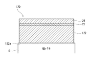
- FIG. 3 is an enlarged cross-sectional view of the protective film 120 according to the second embodiment.
- the protective film 120 of the second embodiment differs from the protective film 20 of the first embodiment in that it does not have the adhesive layer 21. That is, the protective film 120 is formed by laminating the impact absorbing layer 122, the colored layer 23, and the flame retardant layer 24 in this order from the leaf spring 13 side.
- the shock absorbing layer 122 is an acrylic foam adhesive.
- the shock absorbing layer 122 has an adhesive surface 122a attached to the leaf spring 13 on the side opposite to the colored layer 23 side.
- the protective film 120 partially remains on the leaf spring 13 when the protective film 120 is peeled off from the leaf spring 13. This is preferable because it can be prevented. If the adhesive surface 122a of the shock absorbing layer 122 has an adhesive force of 5 N / 20 mm or more, even if the leaf spring 13 is bent or vibrated during traveling of the railway vehicle 1, the protective film 120 is prevented from being displaced or dropped. This is preferable. Since other configurations are the same as those of the first embodiment described above, description thereof is omitted.
- the present invention is not limited to the above-described embodiments, and the configuration can be changed, added, or deleted.
- the members to be protected of the railway vehicle are not limited to leaf springs, and include members that should be protected from flying objects such as other parts of the carriage, a part of the carriage frame or the vehicle body, an under-floor board, and the like.
- the member to be protected is preferably made of fiber reinforced resin.
Landscapes
- Engineering & Computer Science (AREA)
- Mechanical Engineering (AREA)
- Laminated Bodies (AREA)
- Aiming, Guidance, Guns With A Light Source, Armor, Camouflage, And Targets (AREA)
Abstract
鉄道車両台車は、鉄道車両台車の保護対象部材と、前記保護対象部材に貼り付けられる粘着面を有する保護フィルムと、を備える。前記保護フィルムは、前記保護対象部材側から順に、衝撃吸収層と難燃層とが積層され、前記衝撃吸収層が、前記難燃層よりも厚い。
Description
本発明は、保護フィルムを備えた鉄道車両台車及び鉄道車両台車用の保護フィルム付き板バネに関する。
従来、鉄道車両の軽量化を図るために、繊維強化樹脂を用いた台車が開発されている。特許文献1の台車は、繊維強化樹脂製の板バネと、板バネを上方から覆う板バネカバーとを備える。これによれば、板バネカバーにより飛石等が板バネに衝突することが防がれ、繊維強化樹脂の損傷が防がれる。
しかし、特許文献1の板バネカバーは、板バネの下面を保護することはできず、保護領域の選択自由度が低くなる。また、板バネカバーが大きく、板バネカバーを板バネの変形に追随させて動かすための回動機構も必要であるため、車両重量の増加を招くことになる。
これに対し、板バネの表面を塗装により被覆して板バネの保護を図れば、保護領域の設定自由度が高まり、重量増も抑制できる。しかし、メンテナンス時に板バネの劣化等を検査するためには、板バネの表面が簡単に露出可能であることが望まれる。また、鉄道車両においては、使用材料に耐火性能も求められる。なお、前記した事項は、板バネに限られず、鉄道車両を構成する他の部材にも言えることである。
そこで本発明は、鉄道車両台車の保護領域の選択自由度の向上及び車両軽量化を図りながらも、保護対象部材の表面が簡単に露出可能で且つ耐火性能を有する構成を提供することを目的とする。
本発明の一態様に係る保護フィルムを備えた鉄道車両台車は、鉄道車両の保護対象部材と、前記保護対象部材に貼り付けられる粘着面を有する保護フィルムと、を備え、前記保護フィルムは、前記保護対象部材側から順に、衝撃吸収層と難燃層とが積層され、前記衝撃吸収層が、前記難燃層よりも厚い。
前記構成によれば、鉄道車両台車の保護対象部材に保護フィルムを貼り付けるだけであるので、鉄道車両台車の保護領域の選択自由度の向上及び車両軽量化を図ることができると共に、厚肉の衝撃吸収層により走行中の鉄道車両台車の保護対象部材を、バラストや雪塊、その他の飛来物の衝突から良好に保護できる。また、保護フィルムを保護対象部材から剥がすことで、保護対象部材の表面を簡単に露出できるため、メンテナンス時における保護対象部材の検査も容易に行うことができる。更に、保護フィルムの難燃層により、鉄道車両に求められる耐火性能を満たした保護フィルムとすることができる。
本発明によれば、鉄道車両台車の保護領域の選択自由度の向上及び車両軽量化を図りながらも、保護対象部材の表面が簡単に露出可能で且つ耐火性能を有する構成を提供できる。
以下、図面を参照して実施形態を説明する。なお、以下の説明では、鉄道車両が走行する方向であって車体が延びる方向を車両長手方向とし、それに直交する横方向を車幅方向として定義する。
(第1実施形態)
図1は、第1実施形態に係る保護フィルム20を備えた鉄道車両1の側面図である。図1に示すように、鉄道車両1は、台車2と、台車2により下方から支持される車体3とを備える。台車2は、二次サスペンションとなる空気バネ4を介して車体3を支持する台車枠5を備える。台車枠5は、車幅方向に延びる横梁5aを備えるが、横梁5aの車幅方向両端部から車両長手方向に延びる側梁を備えていない。横梁5aの車両長手方向両側には、それぞれ車幅方向に沿って延びる一対の車軸6が配置される。車軸6の車幅方向両側の部分には車輪7が設けられる。車軸6の車幅方向両側の端部には、車輪7よりも車幅方向外側にて車軸6を回転自在に支持する軸受8が設けられ、軸受8は軸箱9に収容される。
図1は、第1実施形態に係る保護フィルム20を備えた鉄道車両1の側面図である。図1に示すように、鉄道車両1は、台車2と、台車2により下方から支持される車体3とを備える。台車2は、二次サスペンションとなる空気バネ4を介して車体3を支持する台車枠5を備える。台車枠5は、車幅方向に延びる横梁5aを備えるが、横梁5aの車幅方向両端部から車両長手方向に延びる側梁を備えていない。横梁5aの車両長手方向両側には、それぞれ車幅方向に沿って延びる一対の車軸6が配置される。車軸6の車幅方向両側の部分には車輪7が設けられる。車軸6の車幅方向両側の端部には、車輪7よりも車幅方向外側にて車軸6を回転自在に支持する軸受8が設けられ、軸受8は軸箱9に収容される。
横梁5aの車幅方向の端部は、軸梁式の軸箱支持装置10によって軸箱9に連結される。軸箱支持装置10は、軸箱9から車両長手方向に横梁5a側に向けて延びた軸梁11を備える。台車枠5は、横梁5aから軸梁11に向けて突出して且つ車幅方向に互いに間隔をあけた一対の受け座12を有し、軸梁11の先端部は、受け座12にゴムブッシュ(図示せず)を介して弾性結合される。車両長手方向に離れた一対の軸箱9は、車両長手方向に延びた板バネ13の長手方向両側の端部13bを夫々支持する。板バネ13の長手方向の中央部13aは、横梁5aの車幅方向の端部を下方から支持する。これにより、横梁5は、板バネ13を介して軸箱9に支持される。即ち、板バネ13は、一次サスペンションの機能と従来の側梁の機能とを兼ねる。
板バネ13は、繊維強化樹脂により形成される。例えば、板バネ13は、その少なくとも上面及び下面を含む部分がCFRPにより形成される。横梁5aの車幅方向端部の下部には、下方に凸な円弧状の下面を有する押圧部材14が設けられ、押圧部材14が板バネ13の中央部13aに上方から載せられて離間可能に接触する。即ち、板バネ13を押圧部材14に対して上下方向に固定しない状態で、横梁5aからの重力による下方荷重によって押圧部材14が板バネ13の上面に接触する。即ち、押圧部材14は、固定具により板バネ13に固定されることなく、横梁5aからの重力による下方荷重とそれに対する板バネ13の反力との接触圧によって板バネ13の上面との接触が保たれた状態となる。
軸箱9の上端部には支持部材15が取り付けられ、板バネ13の端部13bは支持部材15を介して軸箱9に下方から支持される。支持部材15の上面は、側面視で台車中央側に向けて傾斜している。板バネ13の端部13bも、支持部材15に対して上下方向に固定しない状態で支持部材15に上方から載せられる。支持部材15は、軸箱9の上に設置されたベース部材16(例えば、防振ゴム)と、ベース部材16の上に設置されてベース部材16に位置決めされた受部材17とを有する。
受部材17は、板バネ13の端部13bが収容される凹部17aを有し、凹部17aは、上方及び台車中央側に向けて開放されている。受部材17の凹部17aの底面と板バネ13の端部13bとの間には、板バネ13及び受部材17よりも硬度が低い図示しないシート(例えば、ゴムシート)が挟まれている。受部材17には、凹部17aに収容された板バネ13の端部13bを上方から覆うカバー18が締結具(例えば、ボルト)を用いて着脱可能に取り付けられている。
板バネ13は、一対の受け座12の間の空間を通過する。板バネ13の中央部13aは端部13bよりも低く配置され、板バネ13は、側面視で下方に凸な弓形状を有する。板バネ13のうち中央部13aと端部13bとの間の中間領域である中間部13cは、台車2の各部品から離間して空中に自由な状態で配置される。板バネ13の中間部13cは、台車中央側に向けて傾斜している。板バネ13の上面及び下面は、端部13b及び中間部13cにおいて、車幅方向から見て水平面に対して傾斜した傾斜領域を有する。
板バネ13の中間部13cは、その上面及び下面が外部に露出している。そこで、板バネ13の中間部13cの上面及び下面には、保護フィルム20が貼り付けられる。但し、板バネ13のうち他部材に覆われる部位(例えば、板バネ13の中央部13aの上面、及び、板バネ13の端部13bの上下面)には、保護フィルム20が貼り付けられていない。また、板バネ13の車両長手方向に平行な側面にも、保護フィルム20は貼り付けられず、当該側面は外部に露出している。
図2は、図1に示す保護フィルム20の拡大断面図である。図2に示すように、保護フィルム20は、粘着層21と、衝撃吸収層22と、着色層23と、難燃層24とを有する。粘着層21、衝撃吸収層22、着色層23及び難燃層24は、この順に板バネ13(保護対象部材)側から積層されている。粘着層21が、板バネ13に貼り付けられる粘着面21aを有し、難燃層24が、保護フィルム20の外部に露出する表層である。このように保護フィルム20は、各層が合わさった1枚のシート状である。
粘着層21は、衝撃吸収層22側とは反対側において、板バネ13に貼り付けられる粘着面21aを有する。粘着層21は、板バネ13に対する粘着面21aの粘着力が5N/20mm以上かつ35N/20mm以下の材料からなることが好ましく、10N/20mm以上かつ30N/20mm以下の材料からなると更に好ましい。この粘着力は、JIS Z 0237 (2009) に準拠して、被着体に貼り付け後30分後に、引張速度300mm/min、引張角度180°の条件で、塗装された被着体(SUS304BA鋼板)から引き剥がすことにより測定される。粘着層21は、例えば、アクリル系粘着剤を有する。一例として、粘着層21は、粘着剤層単層からなってもよいし、不織布などへ片面もしくは両面に粘着剤を塗布してなる粘着テープであってもよい。粘着層21の厚さは、10μm以上かつ200μm以下であることが好ましく、50μm以上かつ180μm以下であればより好ましく、70μm以上かつ160μm以下であれば更に好ましい。なお、保護フィルム20の板バネ13への貼付前の保管時には、粘着層21の粘着面21aに図示しない剥離ライナー(例えば、PETシート)が取り付けられているとよい。
衝撃吸収層22は、飛来物から板バネ13を機械的に保護するための軟質材からなる。例えば、その軟質材には、-50℃から50℃の間に、周波数1Hzで測定した動的粘弾性測定でのtanδのピークが存在する。例えば、衝撃吸収層22は、多孔質状樹脂からなる。多孔質樹脂の空孔率は、0.1~50体積%が好ましい。衝撃吸収層22は、粘着性を有する。衝撃吸収層22の粘着力は、粘着層21の粘着力よりも大きい。換言すると、板バネ13に対する粘着層21の粘着力は、粘着層21に対する衝撃吸収層22の粘着力よりも小さい。一例として、衝撃吸収層22は、アクリルフォーム粘着剤である。衝撃吸収層22の厚さは、500μm以上かつ4000μm以下であることが好ましく、700μm以上かつ1000μm以下であれば更に好ましい。
着色層23は、衝撃吸収層22と難燃層24との間に挟まれ、着色剤(例えば、顔料)を含んでいる。一例として、着色層23は、不織布の両面に粘着剤を塗布して且つ粘着剤に着色剤を含有させてなる両面粘着テープである。着色層23の粘着剤は、例えば、アクリル系粘着剤である。着色層23の厚さは、1μm以上かつ200μm以下であることが好ましく、3μm以上かつ160μm以下であれば更に好ましい。他の例として、着色層23は、難燃層24に印刷等により塗布された着色剤でもよい。
難燃層24は、難燃性を有し、衝撃吸収層22よりも薄い。難燃層24の引張強度は、粘着層21、衝撃吸収層22及び着色層23の何れの層の引張強度よりも高い。難燃層24の熱膨張率は、粘着層21、衝撃吸収層22及び着色層23の何れの層の熱膨張率よりも低い。難燃層24は、例えば、ポリイミド又は塩化ビニルから選ばれる樹脂、難燃材(例えば、リン系難燃材、ハロゲン系難燃剤、金属水酸化物系難燃剤など)を含有する熱可塑性樹脂、ガラス繊維シート、又は、金属膜(例えば、アルミニウム、ステンレス、銅、チタン又は鉄)である。難燃層24は、透明又は半透明である。本実施形態では、難燃層24に、耐候性の高いポリイミドが用いられる。難燃層24の厚さは、10μm以上かつ400μm以下であると好ましく、30μm以上かつ350μm以下であれば更に好ましい。難燃層24の厚さは、衝撃吸収層22の厚さの1%以上かつ50%以下であることが好ましく、5%以上かつ40%以下であれば更に好ましい。
以上に説明した構成によれば、鉄道車両1の板バネ13に保護フィルム20を貼り付けるだけで板バネ13が保護され、鉄道車両1の保護領域の選択自由度の向上及び車両軽量化を図ることができる。また、衝撃吸収層22は難燃層24よりも厚肉であるので、衝撃吸収層22により走行中の鉄道車両1の板バネ13を飛来物の衝突から良好に保護できる。また、保護フィルム20を板バネ13から剥がすことで、板バネ13の表面を簡単に露出できるため、メンテナンス時における板バネ13の検査(例えば、超音波探傷検査)も容易に行うことができる。更に、保護フィルム20の難燃層24により、鉄道車両に求められる耐火性能を満たした保護フィルムとすることができる。
板バネ13に対する粘着層21の粘着力は、粘着層21に対する衝撃吸収層22の粘着力よりも小さいため、保護フィルム20を板バネ13から引き剥がす際に、保護フィルム20が部分的に板バネ13に残存することが防止され、メンテナンス時における板バネ13の検査を正確に実施できる。粘着層21の粘着力が衝撃吸収層22の粘着力よりも小さいため、保護フィルム20を板バネ13から引き剥がす際に、粘着層21と衝撃吸収層22との間の境界ではなく粘着層21と板バネ13との間の境界にて安定して剥離を生じさせることができる。
板バネ13に貼り付けられる粘着面21aの粘着力が35N/20mm以下であるので、保護フィルム20を板バネ13から引き剥がす際に、保護フィルム20が部分的に板バネ13に残存することをより好適に防止できる。板バネ13に貼り付けられる粘着面21aの粘着力が5N/20mm以上であるので、鉄道車両1の走行中に板バネ13に撓みや振動が生じても、保護フィルム20のズレや脱落を防止できる。
表層としての難燃層24が透明又は半透明であるので、難燃層24を変更することなく着色層23の色を変更することで外部から見た保護フィルム20の色を変更できる。よって、難燃層24の性能を変更することなく色の選択自由度を高めることができる。
難燃層24の引張強度が高いため、保護フィルム20を板バネ13から引き剥がす際に、引張力により保護フィルム20が切れて保護フィルム20が部分的に板バネ13に残存することを防止できる。
難燃層24の厚さが10μm以上であるので、保護フィルム20を板バネ13から引き剥がす際に、引張力により保護フィルム20が切れることをより好適に防止できる。また、難燃層24の厚みにより保護フィルム20の表面に皺が生じることを防ぐことができ、美観性も確保することができる。難燃層24の厚さが400μm以下であるので、保護フィルム20全体の厚肉化を抑制しながらも衝撃吸収層22の厚みが十分に確保され、良好な耐衝撃性を得ることができる。また、衝撃吸収層22が十分に厚いので、板バネ13が繰り返し弾性変形しても、当該変形による歪みが衝撃吸収層22で吸収され、難燃層24への応力伝達を抑制できる。
なお、難燃層24には、ポリイミド等、紫外線による劣化が少ない材料を選択することにより変色が起きにくく、良好な美観を保つことができる。
保護フィルム20は、板バネ13の上下面の傾斜領域のうち外部に露出する箇所に選択的に貼り付けられるので、保護フィルム20の使用量を抑えながらも、高速走行中の鉄道車両1の板バネ13の傾斜領域のうち外部に露出する箇所が飛来物に走行方向に衝突したときに、板バネ13の破損を良好に防止できる。保護フィルム20は、外部に露出しない部位(例えば、板バネ13の端部13bの上下面等)には貼り付けられずに外部に露出した中間部13cに貼り付けられるので、台車2が在姿状態のままで板バネ13に保護フィルム20を容易に着脱できる。
(第2実施形態)
図3は、第2実施形態に係る保護フィルム120の拡大断面図である。図3に示すように、第2実施形態の保護フィルム120は、粘着層21を有さない点で第1実施形態の保護フィルム20と異なる。即ち、保護フィルム120は、衝撃吸収層122と、着色層23と、難燃層24とが、この順に板バネ13側から積層されてなる。一例として、衝撃吸収層122は、アクリルフォーム粘着剤である。衝撃吸収層122は、着色層23側とは反対側において、板バネ13に貼り付けられる粘着面122aを有する。
図3は、第2実施形態に係る保護フィルム120の拡大断面図である。図3に示すように、第2実施形態の保護フィルム120は、粘着層21を有さない点で第1実施形態の保護フィルム20と異なる。即ち、保護フィルム120は、衝撃吸収層122と、着色層23と、難燃層24とが、この順に板バネ13側から積層されてなる。一例として、衝撃吸収層122は、アクリルフォーム粘着剤である。衝撃吸収層122は、着色層23側とは反対側において、板バネ13に貼り付けられる粘着面122aを有する。
衝撃吸収層122の粘着面122aは、その粘着力が35N/20mm以下であると、保護フィルム120を板バネ13から引き剥がす際に、保護フィルム120が部分的に板バネ13に残存することを防止できて好ましい。衝撃吸収層122の粘着面122aは、その粘着力が5N/20mm以上であると、鉄道車両1の走行中に板バネ13に撓みや振動が生じても、保護フィルム120のズレや脱落を防止できて好ましい。なお、他の構成は前述した第1実施形態と同様であるため説明を省略する。
なお、本発明は前述した各実施形態に限定されるものではなく、その構成を変更、追加、又は削除することができる。鉄道車両の保護対象部材は、板バネに限られず、台車の他の部品、台車台枠又は車体の一部、床下のフサギ板等、飛来物等から保護すべき部材が含まれる。その際、保護対象部材は、繊維強化樹脂製であると好ましい。また、保護フィルムには、着色層を設けなくてもよい。
1 鉄道車両
2 台車
13 板バネ(保護対象部材)
13c 中間部(傾斜領域)
20,120 保護フィルム
21 粘着層
21a,122a 粘着面
22,122 衝撃吸収層
23 着色層
24 難燃層
2 台車
13 板バネ(保護対象部材)
13c 中間部(傾斜領域)
20,120 保護フィルム
21 粘着層
21a,122a 粘着面
22,122 衝撃吸収層
23 着色層
24 難燃層
Claims (8)
- 鉄道車両台車の保護対象部材と、
前記保護対象部材に貼り付けられる粘着面を有する保護フィルムと、を備え、
前記保護フィルムは、前記保護対象部材側から順に、衝撃吸収層と難燃層とが積層され、
前記衝撃吸収層が、前記難燃層よりも厚い、鉄道車両台車。 - 前記保護対象部材側から、前記粘着面を有する粘着層が前記衝撃吸収層に積層され、
前記保護対象部材に対する前記粘着層の粘着力は、前記粘着層に対する前記衝撃吸収層の粘着力よりも小さい、請求項1に記載の鉄道車両台車。 - 前記保護対象部材に対する前記粘着面の粘着力は、5N/20mm以上かつ35N/20mm以下である、請求項1又は2に記載の鉄道車両台車。
- 前記難燃層と前記衝撃吸収層との間に着色層が積層され、
前記難燃層は、透明又は半透明である、請求項1乃至3のいずれか1項に記載の鉄道車両台車。 - 前記難燃層は、ポリイミド又は塩化ビニルから選ばれる樹脂、難燃材を含有する熱可塑性樹脂、ガラス繊維シート、又は、金属膜である、請求項1乃至4のいずれか1項に記載の鉄道車両台車。
- 前記難燃層の厚さは、10μm以上かつ400μm以下である、請求項5に記載の鉄道車両台車。
- 鉄道車両台車に搭載され、繊維強化樹脂製の板バネと、
前記板バネに貼り付けられた請求項1乃至6のいずれか1項に記載の保護フィルムと、を備える、鉄道車両台車用の保護フィルム付き板バネ。 - 前記板バネの上下面は、車幅方向から見て水平面に対して傾斜した傾斜領域を有し、
前記保護フィルムは、前記傾斜領域のうち外部に露出する箇所であって、前記板バネの上下面に貼り付けられている、請求項7に記載の鉄道車両台車用の保護フィルム付き板バネ。
Priority Applications (4)
| Application Number | Priority Date | Filing Date | Title |
|---|---|---|---|
| SG11201910149Q SG11201910149QA (en) | 2017-05-01 | 2017-05-01 | Railcar bogie including protective film and protective film-equipped plate spring |
| US16/610,298 US11299184B2 (en) | 2017-05-01 | 2017-05-01 | Railcar bogie including protective film and protective film-equipped plate spring |
| PCT/JP2017/017152 WO2018203367A1 (ja) | 2017-05-01 | 2017-05-01 | 保護フィルムを備えた鉄道車両台車及び保護フィルム付き板バネ |
| CN201780090236.0A CN110891842B (zh) | 2017-05-01 | 2017-05-01 | 具备保护膜的铁道车辆转向架及附有保护膜的板簧 |
Applications Claiming Priority (1)
| Application Number | Priority Date | Filing Date | Title |
|---|---|---|---|
| PCT/JP2017/017152 WO2018203367A1 (ja) | 2017-05-01 | 2017-05-01 | 保護フィルムを備えた鉄道車両台車及び保護フィルム付き板バネ |
Publications (1)
| Publication Number | Publication Date |
|---|---|
| WO2018203367A1 true WO2018203367A1 (ja) | 2018-11-08 |
Family
ID=64016556
Family Applications (1)
| Application Number | Title | Priority Date | Filing Date |
|---|---|---|---|
| PCT/JP2017/017152 Ceased WO2018203367A1 (ja) | 2017-05-01 | 2017-05-01 | 保護フィルムを備えた鉄道車両台車及び保護フィルム付き板バネ |
Country Status (4)
| Country | Link |
|---|---|
| US (1) | US11299184B2 (ja) |
| CN (1) | CN110891842B (ja) |
| SG (1) | SG11201910149QA (ja) |
| WO (1) | WO2018203367A1 (ja) |
Cited By (1)
| Publication number | Priority date | Publication date | Assignee | Title |
|---|---|---|---|---|
| US11299184B2 (en) * | 2017-05-01 | 2022-04-12 | Kawasaki Jukogyo Kabushiki Kaisha | Railcar bogie including protective film and protective film-equipped plate spring |
Citations (8)
| Publication number | Priority date | Publication date | Assignee | Title |
|---|---|---|---|---|
| JPH0561140B2 (ja) * | 1986-04-11 | 1993-09-03 | Messerschmitt Boelkow Blohm | |
| JPH06144223A (ja) * | 1992-11-09 | 1994-05-24 | Railway Technical Res Inst | 鉄道車両用構造体 |
| US5690034A (en) * | 1993-10-06 | 1997-11-25 | Abb Daimler-Benz Transportation (Deutschland) Gmbh | Composite-material push-pull link bar for rail vehicles |
| WO1998017519A1 (en) * | 1995-08-22 | 1998-04-30 | Abb Daimler-Benz Transportation (Sweden) Ab | Deicing device |
| JP2002047461A (ja) * | 2000-08-02 | 2002-02-12 | Yazaki Corp | ノンハロゲン粘着テープ |
| JP2012097248A (ja) * | 2010-10-06 | 2012-05-24 | Kaneka Corp | 熱成形用フィルム向け硬化性樹脂組成物とこの樹脂組成物を積層した熱成形用フィルム |
| WO2012137257A1 (ja) * | 2011-04-07 | 2012-10-11 | 川崎重工業株式会社 | 鉄道車両用台車 |
| JP2015003559A (ja) * | 2013-06-19 | 2015-01-08 | 川崎重工業株式会社 | 板バネカバー及びそれを備えた鉄道車両用台車 |
Family Cites Families (13)
| Publication number | Priority date | Publication date | Assignee | Title |
|---|---|---|---|---|
| JPH06166153A (ja) | 1993-04-09 | 1994-06-14 | Tsutsunaka Plast Ind Co Ltd | 印刷層を有する合成樹脂積層板の製造方法 |
| JP4585164B2 (ja) | 2002-07-18 | 2010-11-24 | 日東電工株式会社 | 紫外線硬化型粘着シート |
| CN2789019Y (zh) * | 2005-04-26 | 2006-06-21 | 汕头市汉信实业有限公司 | 一种用于制作装饰珠片的片材 |
| CN2909289Y (zh) * | 2006-01-11 | 2007-06-06 | 李成威 | 万能调色偏光片 |
| JP2012086438A (ja) | 2010-10-19 | 2012-05-10 | Nitto Denko Corp | 高強度難燃ポリマー部材 |
| JP5576990B2 (ja) * | 2011-09-15 | 2014-08-20 | 株式会社ジーエイチクラフト | 鉄道車両台車用板バネ |
| KR20150000553A (ko) * | 2013-06-24 | 2015-01-05 | 삼성디스플레이 주식회사 | 표시장치 및 그 제조방법 |
| KR20150000553U (ko) * | 2013-07-26 | 2015-02-04 | 현대중공업 주식회사 | 연마가루의 비산 방지 및 수거 처리 기능을 구비하는 포집장치 |
| CN104442611A (zh) * | 2013-09-20 | 2015-03-25 | 西川橡胶工业股份有限公司 | 防水用密封件以及使用了该防水用密封件的密封方法 |
| JP6247494B2 (ja) * | 2013-10-09 | 2017-12-13 | 川崎重工業株式会社 | 鉄道車両台車用の板バネの製造方法 |
| DE102013017571A1 (de) * | 2013-10-24 | 2015-04-30 | Carl Freudenberg Kg | Elastomerer Körper zur Schwingungsdämpfung |
| CN205556536U (zh) * | 2015-12-25 | 2016-09-07 | 琳得科株式会社 | 遮光用双面粘贴带及使用该粘贴带的液晶面板、电子产品 |
| CN110891842B (zh) * | 2017-05-01 | 2022-04-29 | 川崎重工业株式会社 | 具备保护膜的铁道车辆转向架及附有保护膜的板簧 |
-
2017
- 2017-05-01 CN CN201780090236.0A patent/CN110891842B/zh active Active
- 2017-05-01 SG SG11201910149Q patent/SG11201910149QA/en unknown
- 2017-05-01 US US16/610,298 patent/US11299184B2/en active Active
- 2017-05-01 WO PCT/JP2017/017152 patent/WO2018203367A1/ja not_active Ceased
Patent Citations (8)
| Publication number | Priority date | Publication date | Assignee | Title |
|---|---|---|---|---|
| JPH0561140B2 (ja) * | 1986-04-11 | 1993-09-03 | Messerschmitt Boelkow Blohm | |
| JPH06144223A (ja) * | 1992-11-09 | 1994-05-24 | Railway Technical Res Inst | 鉄道車両用構造体 |
| US5690034A (en) * | 1993-10-06 | 1997-11-25 | Abb Daimler-Benz Transportation (Deutschland) Gmbh | Composite-material push-pull link bar for rail vehicles |
| WO1998017519A1 (en) * | 1995-08-22 | 1998-04-30 | Abb Daimler-Benz Transportation (Sweden) Ab | Deicing device |
| JP2002047461A (ja) * | 2000-08-02 | 2002-02-12 | Yazaki Corp | ノンハロゲン粘着テープ |
| JP2012097248A (ja) * | 2010-10-06 | 2012-05-24 | Kaneka Corp | 熱成形用フィルム向け硬化性樹脂組成物とこの樹脂組成物を積層した熱成形用フィルム |
| WO2012137257A1 (ja) * | 2011-04-07 | 2012-10-11 | 川崎重工業株式会社 | 鉄道車両用台車 |
| JP2015003559A (ja) * | 2013-06-19 | 2015-01-08 | 川崎重工業株式会社 | 板バネカバー及びそれを備えた鉄道車両用台車 |
Cited By (1)
| Publication number | Priority date | Publication date | Assignee | Title |
|---|---|---|---|---|
| US11299184B2 (en) * | 2017-05-01 | 2022-04-12 | Kawasaki Jukogyo Kabushiki Kaisha | Railcar bogie including protective film and protective film-equipped plate spring |
Also Published As
| Publication number | Publication date |
|---|---|
| CN110891842A (zh) | 2020-03-17 |
| SG11201910149QA (en) | 2019-11-28 |
| CN110891842B (zh) | 2022-04-29 |
| US11299184B2 (en) | 2022-04-12 |
| US20200079402A1 (en) | 2020-03-12 |
Similar Documents
| Publication | Publication Date | Title |
|---|---|---|
| US9428199B2 (en) | Railcar bogie plate spring | |
| CN107532671B (zh) | 板簧单元和铁道车辆用转向架 | |
| US8327772B2 (en) | Low-floor railway vehicle bogie and low-floor railway vehicle comprising the bogie | |
| JP6973413B2 (ja) | シール部材付きウインドウガラス | |
| EP2689986B1 (en) | Railcar including heat-resistant floor | |
| JP6741430B2 (ja) | 保護フィルムを備えた鉄道車両台車及び保護フィルム付き板バネ | |
| KR20200049851A (ko) | 충격 성능이 개선된 만곡된 커버 유리를 갖는 차량 인테리어 시스템 및 이를 형성하는 방법 | |
| JP2018516192A (ja) | 補強された非常口基材を有する輸送手段側面グレージング | |
| WO2018203367A1 (ja) | 保護フィルムを備えた鉄道車両台車及び保護フィルム付き板バネ | |
| CN101514730A (zh) | 球形结构和v形结构相结合的一系弹簧 | |
| JP2002154430A (ja) | 鉄道車両 | |
| CN101389471A (zh) | 保护装置 | |
| TWI671223B (zh) | 具備保護膜之鐵道車輛台車及附保護膜之板彈簧 | |
| JP2006290054A (ja) | 高速鉄道車両の低騒音車体構造 | |
| JP4399299B2 (ja) | 高速鉄道車両の台車カバー | |
| JP2015174527A (ja) | プラットホームドア装置のドア | |
| TOMIOKA et al. | Reduction of carbody flexural vibration by the high-damping elastic support of under-floor equipment | |
| CN102245457B (zh) | 具有震动吸收器件的线缆运输装置 | |
| CN210707114U (zh) | 一种危险品运输车内危险品防碰撞结构 | |
| GB2411632A (en) | Rail vehicle cabin with yieldable parts | |
| JPH07232640A (ja) | 鉄道車両用窓構造 | |
| CN100430279C (zh) | 一种车站站台缓冲防滑安全防护装置 | |
| Dižo et al. | Passive safety in railway vehicles: a review | |
| Sapuan et al. | Safety Issues in Transportation Design | |
| JPH06101201A (ja) | レールの制振方法及び制振材 |
Legal Events
| Date | Code | Title | Description |
|---|---|---|---|
| 121 | Ep: the epo has been informed by wipo that ep was designated in this application |
Ref document number: 17908455 Country of ref document: EP Kind code of ref document: A1 |
|
| NENP | Non-entry into the national phase |
Ref country code: DE |
|
| 122 | Ep: pct application non-entry in european phase |
Ref document number: 17908455 Country of ref document: EP Kind code of ref document: A1 |
|
| NENP | Non-entry into the national phase |
Ref country code: JP |