WO2018202034A1 - 用于无线通信的电子设备和方法 - Google Patents
用于无线通信的电子设备和方法 Download PDFInfo
- Publication number
- WO2018202034A1 WO2018202034A1 PCT/CN2018/085312 CN2018085312W WO2018202034A1 WO 2018202034 A1 WO2018202034 A1 WO 2018202034A1 CN 2018085312 W CN2018085312 W CN 2018085312W WO 2018202034 A1 WO2018202034 A1 WO 2018202034A1
- Authority
- WO
- WIPO (PCT)
- Prior art keywords
- fleet
- link
- electronic device
- network
- members
- Prior art date
- Legal status (The legal status is an assumption and is not a legal conclusion. Google has not performed a legal analysis and makes no representation as to the accuracy of the status listed.)
- Ceased
Links
Images


Classifications
-
- H—ELECTRICITY
- H04—ELECTRIC COMMUNICATION TECHNIQUE
- H04W—WIRELESS COMMUNICATION NETWORKS
- H04W4/00—Services specially adapted for wireless communication networks; Facilities therefor
- H04W4/06—Selective distribution of broadcast services, e.g. multimedia broadcast multicast service [MBMS]; Services to user groups; One-way selective calling services
- H04W4/08—User group management
-
- H—ELECTRICITY
- H04—ELECTRIC COMMUNICATION TECHNIQUE
- H04W—WIRELESS COMMUNICATION NETWORKS
- H04W4/00—Services specially adapted for wireless communication networks; Facilities therefor
- H04W4/80—Services using short range communication, e.g. near-field communication [NFC], radio-frequency identification [RFID] or low energy communication
-
- H—ELECTRICITY
- H04—ELECTRIC COMMUNICATION TECHNIQUE
- H04W—WIRELESS COMMUNICATION NETWORKS
- H04W4/00—Services specially adapted for wireless communication networks; Facilities therefor
- H04W4/30—Services specially adapted for particular environments, situations or purposes
- H04W4/40—Services specially adapted for particular environments, situations or purposes for vehicles, e.g. vehicle-to-pedestrians [V2P]
- H04W4/46—Services specially adapted for particular environments, situations or purposes for vehicles, e.g. vehicle-to-pedestrians [V2P] for vehicle-to-vehicle communication [V2V]
-
- H—ELECTRICITY
- H04—ELECTRIC COMMUNICATION TECHNIQUE
- H04L—TRANSMISSION OF DIGITAL INFORMATION, e.g. TELEGRAPHIC COMMUNICATION
- H04L67/00—Network arrangements or protocols for supporting network services or applications
- H04L67/01—Protocols
- H04L67/12—Protocols specially adapted for proprietary or special-purpose networking environments, e.g. medical networks, sensor networks, networks in vehicles or remote metering networks
-
- H—ELECTRICITY
- H04—ELECTRIC COMMUNICATION TECHNIQUE
- H04W—WIRELESS COMMUNICATION NETWORKS
- H04W24/00—Supervisory, monitoring or testing arrangements
- H04W24/04—Arrangements for maintaining operational condition
-
- H—ELECTRICITY
- H04—ELECTRIC COMMUNICATION TECHNIQUE
- H04W—WIRELESS COMMUNICATION NETWORKS
- H04W4/00—Services specially adapted for wireless communication networks; Facilities therefor
-
- H—ELECTRICITY
- H04—ELECTRIC COMMUNICATION TECHNIQUE
- H04W—WIRELESS COMMUNICATION NETWORKS
- H04W72/00—Local resource management
- H04W72/02—Selection of wireless resources by user or terminal
-
- H—ELECTRICITY
- H04—ELECTRIC COMMUNICATION TECHNIQUE
- H04W—WIRELESS COMMUNICATION NETWORKS
- H04W72/00—Local resource management
- H04W72/04—Wireless resource allocation
-
- H—ELECTRICITY
- H04—ELECTRIC COMMUNICATION TECHNIQUE
- H04W—WIRELESS COMMUNICATION NETWORKS
- H04W72/00—Local resource management
- H04W72/50—Allocation or scheduling criteria for wireless resources
- H04W72/52—Allocation or scheduling criteria for wireless resources based on load
-
- H—ELECTRICITY
- H04—ELECTRIC COMMUNICATION TECHNIQUE
- H04W—WIRELESS COMMUNICATION NETWORKS
- H04W72/00—Local resource management
- H04W72/50—Allocation or scheduling criteria for wireless resources
- H04W72/54—Allocation or scheduling criteria for wireless resources based on quality criteria
- H04W72/542—Allocation or scheduling criteria for wireless resources based on quality criteria using measured or perceived quality
-
- H—ELECTRICITY
- H04—ELECTRIC COMMUNICATION TECHNIQUE
- H04W—WIRELESS COMMUNICATION NETWORKS
- H04W84/00—Network topologies
- H04W84/18—Self-organising networks, e.g. ad-hoc networks or sensor networks
- H04W84/20—Leader-follower arrangements
-
- H—ELECTRICITY
- H04—ELECTRIC COMMUNICATION TECHNIQUE
- H04W—WIRELESS COMMUNICATION NETWORKS
- H04W88/00—Devices specially adapted for wireless communication networks, e.g. terminals, base stations or access point devices
- H04W88/02—Terminal devices
-
- H—ELECTRICITY
- H04—ELECTRIC COMMUNICATION TECHNIQUE
- H04W—WIRELESS COMMUNICATION NETWORKS
- H04W72/00—Local resource management
- H04W72/20—Control channels or signalling for resource management
-
- H—ELECTRICITY
- H04—ELECTRIC COMMUNICATION TECHNIQUE
- H04W—WIRELESS COMMUNICATION NETWORKS
- H04W84/00—Network topologies
- H04W84/005—Moving wireless networks
-
- H—ELECTRICITY
- H04—ELECTRIC COMMUNICATION TECHNIQUE
- H04W—WIRELESS COMMUNICATION NETWORKS
- H04W92/00—Interfaces specially adapted for wireless communication networks
- H04W92/16—Interfaces between hierarchically similar devices
- H04W92/18—Interfaces between hierarchically similar devices between terminal devices
Definitions
- Embodiments of the present invention generally relate to the field of wireless communications, and more particularly to system configurations in a car network, and more particularly to electronic devices and methods for wireless communication.
- V2V Internet of Vehicles
- the core goal of the Internet of Vehicles is to ensure that vehicle driving status or accident warning information can be reliably and quickly interacted between vehicles to ensure safe driving and reduce the impact of accidents.
- the current research V2X mainly adds support for advanced driving styles.
- Advanced driving methods include Vehicles Platooning, Semi-automated driving, Full-automated driving and Remote Driving.
- the fleet communication system can be described as a group of vehicles driving in a relatively close chain manner.
- the information that needs to be exchanged between the vehicles includes at least: vehicle speed, running direction, intentions such as braking, acceleration, and the like.
- Driving in a fleet can reduce vehicle spacing, reduce energy consumption and reduce the number of drivers. All team members are located within the communication range of direct neighbors who are also members of the team. Therefore, in the fleet communication system, the demand for low latency and high reliability of communication between fleet members is more stringent. There is a need to provide link management techniques that are tailored to the actual needs of the fleet driving style.
- an electronic device for wireless communication comprising: processing circuitry configured to: confirm a network structure of a fleet; and determine a link stability measurement configuration corresponding to the network structure, the chain The road stability measurement configuration is used by the receiving end device of the link to determine the stability of the link according to the reception status of the transmission content.
- an electronic device for wireless communication comprising: processing circuitry configured to: perform link stability measurement based on a link stability measurement configuration for a link, wherein The receiving end of the link is the vehicle where the electronic device is located, the transmitting end of the link is the other vehicle in the fleet; and the corresponding event is triggered according to the measured result.
- a method for wireless communication comprising: confirming a network structure of a fleet; and determining a link stability measurement configuration corresponding to a network structure, the link stability measurement configuration configured for The receiving end device of the link determines the stability of the link based on the reception status of the transmitted content.
- a method for wireless communication comprising: measuring link stability based on a link stability measurement configuration for a link, wherein the receiving end of the link is the electronic The vehicle where the equipment is located, the sender of the link is the other vehicle in the fleet; and the corresponding event is triggered according to the result of the measurement.
- the above-described electronic device and method according to the present application can perform link stability measurement by adopting a link stability measurement configuration corresponding to a network structure of a fleet, and can quickly and accurately measure the stability of a link in a fleet, thereby realizing a fleet Highly reliable, low latency communication for members.
- an electronic device for wireless communication comprising: processing circuitry configured to: acquire parameters related to a perceived operation of a fleet member; and generate, based on the parameter, a plurality of The perceived configuration of the fleet members, multiple fleet members based on the perceived configuration for collaborative awareness.
- a method for wireless communication comprising: obtaining parameters related to a perceived operation of a fleet member; and generating a perceptual configuration for a plurality of fleet members in the fleet based on the parameter, Team members are collaboratively aware based on this perceptual configuration.
- the above-described electronic device and method according to the present application improves the accuracy and speed of perception by generating a perceptual configuration for each fleet member to enable a plurality of fleet members to achieve cooperative sensing, thereby achieving highly reliable, low-latency communication of fleet members.
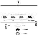
- Figure 1 shows an example of an entity in a fleet driving mode
- FIG. 2 shows a functional block diagram of an electronic device for wireless communication in accordance with one embodiment of the present application
- FIG. 3 illustrate five examples of the architecture of network communication of one embodiment of the present application
- FIG. 4 shows a functional block diagram of an electronic device for wireless communication in accordance with one embodiment of the present application
- Figure 5 illustrates a flow diagram of information interaction between a network and a fleet manager in accordance with one embodiment of the present application
- FIG. 6 shows a functional block diagram of an electronic device for wireless communication in accordance with one embodiment of the present application
- FIG. 7 is a schematic diagram showing the flow of information between a fleet manager and a team member in accordance with one embodiment of the present application.
- FIG. 8 shows a functional block diagram of an electronic device for wireless communication in accordance with one embodiment of the present application.
- FIG. 9 is a schematic diagram showing an information flow of activating link stability measurement and triggering event processing according to an embodiment of the present application.
- FIG. 10 illustrates a functional block diagram of an electronic device for wireless communication in accordance with another embodiment of the present application.
- FIG. 11 is a schematic diagram showing an information flow of resource configuration adjustment according to an embodiment of the present application.
- FIG. 12 is a schematic diagram showing an information flow of interrupt processing according to an embodiment of the present application.
- FIG. 13 illustrates a functional block diagram of an electronic device for wireless communication in accordance with another embodiment of the present application
- FIG. 14 illustrates an information flow when a vehicle joins a fleet according to an embodiment of the present application
- Figure 15 illustrates an illustrative example of an application for determining the location of a user of a perceived spectrum relative to a fleet based on the results of the collaborative perception
- FIG. 16 shows a flow chart of a method for wireless communication in accordance with one embodiment of the present application
- FIG. 17 shows a flow chart of a method for wireless communication in accordance with another embodiment of the present application.
- FIG. 18 shows a flow chart of a method for wireless communication in accordance with another embodiment of the present application.
- 19 is a block diagram showing an example of a schematic configuration of a smartphone that can apply the technology of the present disclosure
- 20 is a block diagram showing an example of a schematic configuration of a car navigation device to which the technology of the present disclosure can be applied;
- 21 is a block diagram of an exemplary structure of a general purpose personal computer in which methods and/or apparatus and/or systems in accordance with embodiments of the present invention may be implemented.
- Figure 1 shows an example of an entity in a fleet driving mode.
- the team creator (Platooning Creator) is responsible for creating the fleet.
- the Platoning Leader manages the fleet.
- the fleet creator and fleet manager may be the same or different.
- the other vehicles in the fleet are called the Platoning Member. It should be understood that in the following, where appropriate, such as in describing features for all vehicles in the fleet, fleet members may also include fleet managers.
- the fleet manager updates the surrounding traffic information from the team members in real time and reports them to the Road Side Unit (RSU).
- RSU Road Side Unit
- fleet managers can receive traffic information from roadside equipment from roadside equipment and share it with team members. All team members can share information within the fleet via a V2X straight link (Sidelink, or PC5 link).
- V2X straight link Sidelink, or PC5 link.
- This embodiment proposes an electronic device for link stability measurement in a fleet.
- 2 shows a functional block diagram of the electronic device 100.
- the electronic device 100 includes: a confirmation unit 101 configured to confirm a network structure of a fleet; and a determining unit 102 configured to determine and network structure Corresponding link stability measurement configuration, the link stability measurement configured by the receiving end device of the link determines the stability of the link according to the reception status of the transmission content.
- the confirmation unit 101 and the determination unit 102 can be implemented by one or more processing circuits, which can be implemented, for example, as a chip.
- the electronic device 100 can be located, for example, in a fleet manager.
- the fleet's network structure may include one or more of the following: Platoon Size; fleet form; architecture of network communications.
- the size of the team can be the number of team members included in the team.
- the form of the team is the organization of the team, such as a fleet of cars (as shown in the example of Figure 1) or a fleet of co-drivers that are not necessarily arranged in a row but are flexible.
- the architecture of network communication represents the way in which members of the fleet communicate, such as the composition of the link and the specific form of communication.
- A) to e) of Fig. 3 show five examples of the architecture of network communication.
- the five forms of network architecture are described separately below. However, it should be understood that the present application is not limited to the architecture of the network communication shown in FIG. 3, which is merely illustrative.
- the data transmission direction toward the fleet manager in the data link is defined as Forward Transmission, and the transmission direction away from the fleet manager is Backward Transmission; the closest in the forward transmission is defined.
- the neighbor member is called the predecessor of the current member, and the closest neighbor member in the backward transmission is called the successor of the current member.
- the fleet manager broadcasts information to the team members, and the team members send information to the fleet manager via a single-hop link, such as V3 ⁇ V1. If the same reception quality is to be achieved at the fleet manager, the closer the transmission member is to the manager, the smaller the transmission power.
- the fleet manager broadcasts information to the fleet members, and the team members use the one-way link between the adjacent fleet members to send information to the fleet manager.
- the team members establish a unidirectional link with the predecessor members, such as V3 ⁇ V2. This constitutes a one-way forward transmission link between two adjacent fleet members. Because the adjacent car is close, the link requires only a low transmit power.
- the fleet manager broadcasts information to the fleet members and there is a two-way link between adjacent fleet members. That is, on the basis of the architecture b, a unidirectional link between the fleet members and the successor members is added, for example, V2 ⁇ V3. This forms a two-way link between two adjacent fleet members.
- the advantage of this architecture is that information interaction between adjacent fleet members is easy to implement.
- the fleet is divided into a plurality of clusters, and the adjacent cluster managers exchange information through the bidirectional links, and each cluster can be configured by any one of a to d, respectively.
- This architecture is especially suitable for larger fleets.
- the number of fleet members that can be supported in LTE eV2X can be up to 19.
- the fleet can be divided into clusters according to architecture e, each cluster consisting of cluster managers and cluster members.
- the fleet manager also acts as the cluster manager of the first cluster, and the adjacent cluster managers form a bidirectional link, and the clusters can be constructed arbitrarily according to the structures a to d.
- the fleet manager only needs to manage the cluster manager, which is managed by the cluster manager.
- electronic device 100 can also be located in a cluster manager.
- the architecture of the network communication within the fleet can be set according to the size of the fleet, the communication power setting, and the like.
- the size of the team can be the number of team members included in the team. For example, when the fleet size is below the threshold N1 (such as 3), choose architecture a; when the fleet size is greater than N1 is less than N2 (such as 5), choose architecture b; when the fleet size is greater than N1 is less than N2, and need adjacent vehicles
- choose the architecture c when the fleet manager has limited transmission power, choose the architecture d; when the fleet size is greater than N2, you need to cluster first, select the cluster manager, and the network structure in each cluster can be managed by the fleet.
- the unified selection can also be selected by the cluster manager.
- the validation unit 101 and the determination unit 102 may, for example, perform respective operations in response to at least one of: a predetermined time elapses; a fleet size change; a change in information interaction requirements of the fleet members; an available network transmission resource change.
- the operations of the validation unit 101 and the determination unit 102 may be periodic and/or triggered.
- the confirmation unit 101 and the determination unit 102 perform operations in a predetermined cycle, and can determine changes in the network structure in time, such as entry and departure of fleet members, changes in the form of the fleet, changes in the network communication architecture of the fleet, such as changing from architecture a to architecture c. Wait.
- the validation unit 101 and the determination unit 102 can also operate via triggering.
- the trigger condition can be any condition that may cause a change in the network structure.
- the architecture of the fleet's network communications may change.
- the architecture of the network communication may change when the information exchange requirements of the fleet members change, for example, when the amount of information to be exchanged changes due to the state of travel or changes in the state of the surrounding traffic environment.
- a quantitative parameter of information exchange between team members may be the amount of information that a single team member needs to report in a unit time, or the amount of information that a single link needs to transmit in a unit time, which is recorded as MessageSizePerUnit, as described later,
- the parameters can be related to the network structure.
- the trigger condition may also be a change of available transmission resources notified by the network (eNB/RSU), in which case it may be necessary to change the network structure to accommodate changes in the transmission resources.
- the link configuration in the fleet may be different, and therefore, the determining unit 102 determines a corresponding link stability measurement configuration according to the network structure.
- the link stability measurement is configured for the receiving end device of the link to determine the stability of the link according to the reception status of the transmitted content. In other words, the transmission status of the link is utilized to evaluate the stability of the link.
- LTE provides two link quality measurement parameters related to the pass-through link, namely, the direct link reference signal received power (S-RSRP) and the direct link discovery reference signal received power SD-RSRP (Sidelink discovery). Reference signal received power).
- S-RSRP direct link reference signal received power
- SD-RSRP Securelink discovery reference signal received power
- the present embodiment utilizes the characteristics that the vehicles in the fleet frequently exchange information, so that the receiving vehicle can evaluate the stability of the link by monitoring the state of the receiving while receiving useful information, thereby significantly reducing the control signaling overhead.
- the stability of the link is accurately assessed with the resulting delay and required energy consumption.
- the method of the embodiment can also reduce the control signaling overhead and the required energy consumption, and improve the actual situation. Data transmission efficiency.
- the link stability measurement configuration includes, for example, a correspondence between a link transmission mode and link stability.
- the link transmission mode includes, for example, the number of times the transmission is performed on the link within a predetermined time, and the link stability includes a fixed duration such as the number or rate of successful reception within a unit time period.
- the transmission content may be signaling such as beacon, control signaling, discovery message, data, and the like.
- the link transmission mode may be an interval period during which transmission is performed on the link, and the link stability is a ratio of successful reception within a fixed period of time.
- the electronic device 100 can support two centrally controlled scheduling methods, which are determined and provided by the eNB/RSU, namely Dynamic Scheduling and Semi-persistent Scheduling (SPS).
- SPS Semi-persistent Scheduling
- dynamic scheduling has to make new scheduling decisions on each subframe, that is, the location of decision resources. This method has high flexibility in resource usage.
- the semi-persistent scheduling in addition to the resource location, also determines the scheduling interval, that is, the transmission period information.
- the resource location only needs to be sent once by the PDCCH, and the transmission period is configured through RRC signaling, that is, the scheduled resource can be used in a set period. .
- This method reduces the signaling overhead and is suitable for the cyclical transmission requirements of the data volume, such as for transmission in the fleet driving mode. Therefore, when SPS is adopted, the link stability measurement configuration will depend on the specific resource allocation method. On the other hand, when SPS is not used, the transmission may not be periodic, but the transmission resources allocated for each link will also affect the number of transmissions within a predetermined time, thereby affecting the link stability measurement configuration.
- the determining unit 102 can be configured to determine a link stability measurement configuration for the link to provide to the respective fleet member based on the transmission resources allocated for each link.
- the link stability measurement configuration is also affected by the network environment such as the number and density of surrounding vehicles, the number and frequency of surrounding vehicle messages, and the type of content being transmitted, and so on.
- the link stability may also be the number of transmissions that have not been successfully received in a fixed duration, or the ratio of the number of transmissions to the expected number of transmissions.
- the link stability may also be that the message parsed information indicates that the distance is stable for a certain period of time.
- the link stability measurement configuration may be obtained from the network, or may be determined based on a correspondence between the pre-stored network structure and the link stability measurement configuration. Furthermore, as previously described, for each link, the determining unit 102 can also adjust its link stability measurement configuration based on the allocated transmission resources.
- the transmission resources required for communication in the fleet are requested, for example, by the fleet manager to the network, such as the eNB or RSU, and the fleet resources are allocated by the fleet manager within the fleet.
- the electronic device 100 further includes a generating unit 103 configured to generate a resource allocation request based on the confirmed network structure for requesting the network to allocate network transmission resources for the fleet.
- the generating unit 103 can estimate the total amount of resource demand inside the fleet and include the estimated total amount of resource demand in the resource allocation request.
- the fleet's internal resource requirements include the dispatch of the fleet manager/fleet cluster manager and the resources required by the fleet manager/or team members to return the message.
- the generating unit 103 may perform estimation based on at least one of a network structure, a data processing mode of the forwarding node, and an amount of information to be transmitted by the fleet member in a unit time.
- the data processing mode of the forwarding node may include forwarding only or merge forwarding, and the amount of resources required by the two methods is different.
- the generating unit 103 may determine the amount of information to be transmitted by the fleet members in a unit time based on the network structure, wherein the network structure has a correspondence with the amount of information that the fleet members are to transmit in a unit time. This correspondence can be stored, for example, in advance in the storage device of the fleet manager. In this way, after confirming the network structure, the amount of information that the team members are to transmit in a unit time can be known.
- the SPS resource allocation method is suitable for communication in the fleet driving mode, and therefore, the generating unit 103 can generate one or more SPS configuration requests as resource allocation requests based on the estimated total resource demand amount.
- each vehicle or each link may require one or more SPS configurations, and the generating unit 103 may combine these SPS configurations based on considerations of reducing the amount of information required for resource allocation request signaling.
- the method of merging includes, for example, SPS configuration merging for the same transmission start time and interval period, or merging for the SPS configuration of the same spectral resource on the interval period, the result of the merging may result in one or more SPS configuration requests.
- multiple SPS configurations per vehicle or each link may be used for the interaction of different types of information.
- the resource allocation request generated by the generating unit 103 includes an identification of the network architecture of the fleet and information on the size of the fleet.
- the network can confirm the network architecture of the fleet according to the identification of the network architecture of the fleet, so that the total fleet resource demand can be estimated in combination with the fleet size. In other words, the estimate of the total demand for fleet resources is made on the network side.
- the network can allocate resources to the fleet based on the total fleet resource demand, including, for example, spectrum resources and time configuration.
- the network side can generate one or more SPS configurations.
- the electronic device 100 may further include a transceiving unit configured to transmit a resource allocation request to the network and receive a resource allocation result from the network.
- the transceiver unit can be implemented, for example, as an antenna and a corresponding transceiver circuit or the like.
- Figure 5 shows a flow diagram of information interaction between the network side and the fleet manager.
- the fleet manager triggers the confirmation of the fleet network structure in response to, for example, one of the foregoing specific conditions, and generates a resource allocation request, and sends the resource allocation request to the network (eNB/RSU), and the eNB/RSU performs resource allocation according to the request.
- a resource allocation response is sent to the fleet manager.
- the resource allocation response may further include a link stability measurement configuration corresponding to the network structure.
- the fleet manager After acquiring the transmission resources, the fleet manager allocates transmission resources within the fleet. Accordingly, as shown in FIG. 6, the electronic device 100 may further include an allocating unit 104 configured to perform allocation of transmission resources within the fleet.
- the allocation unit 104 allocates transmission resources to the fleet members according to the previously confirmed network structure and the requirements of the respective links. If the transmission resource allocated by the network is less than the total resource demand of the fleet, the confirmation unit 101 may adjust the network structure of the fleet, such as the architecture of the network communication of the fleet, based on the network transmission resources actually allocated by the network, and the allocation unit 104. The allocation of transmission resources within the fleet is based on the adjusted network structure.
- the network may also include an adjustable range of the network transmission resources when allocating network transmission resources to the fleet, and the allocating unit 104 notifies the team members of the adjustable range when allocating transmission resources to the fleet members.
- the adjustable range may include at least reducing the frequency or number of times the message is sent within a range that meets the resource allocation, or is adjusted to restore the original resource configuration.
- the adjustable range can also be set by the fleet manager.
- the reason for setting the adjustable range is that when the running state of the vehicle is stable or the link quality is good, the frequency of data exchange can be reduced, so that the required transmission resources can be reduced.
- each member of the fleet can communicate based on the assignment result while measuring the link according to the stability measurement configuration. Stability.
- Figure 7 shows a schematic diagram of the flow of information between the fleet manager and the team members.
- the fleet manager allocates transmission resources to each member (or each link) according to the network structure, and provides the resource allocation result to each member.
- the resource allocation results shown in FIG. 7 also include the above-described stability measurement configuration and/or resource adjustable range.
- the team members perform communication and link stability measurements based on the resource allocation results.
- the electronic device 100 may further include an event processing unit 105 configured to process the corresponding event based on the result of the link stability measurement.
- events include, for example, link resource configuration adjustments, interrupt handling, and the like.
- the results of the link stability measurements described herein may include link stability measurements for fleet members, as well as link stability measurements for the fleet manager or cluster manager itself.
- the electronic device 100 may further include the generating unit 103 and the allocating unit 104 shown in FIG. 6.
- the frequency of data interaction can be reduced, and vice versa.
- the adjustment of the data exchange frequency also needs to meet the frequency range required by the data type.
- the driving safety related information may have the lowest frequency limit, and the data interaction frequency adjustment result must satisfy the minimum frequency limit.
- the adjustment of the data exchange frequency also needs to meet the inherent limitation of the data update capability. For example, if the frequency of data update processed by the onboard control system by the sensor may have the highest frequency limit, the data exchange frequency adjustment result may be considered. The highest frequency limit reduces unnecessary information interaction.
- allocation unit 104 can be configured to perform a reallocation of transmission resources within the fleet based on link stability measurements.
- the resource configuration change is within the resource adjustable range, such as reducing the frequency of data interaction or restoring the original resource configuration
- the sender device of the link can adjust itself, and the receiving device of the link This adjustment can be reported to the fleet manager or cluster manager.
- the resource allocation for the link may also be adjusted accordingly by the allocation unit 104.
- resource allocation will be performed by the allocation unit 104.
- the allocating unit 104 can also perform reallocation of transmission resources within the fleet based on changes in the amount of information to be transmitted by the fleet members. For example, the amount of information that a team member is to transmit is affected by the driving state of the vehicle and the surrounding traffic conditions. In the case where the running state is unstable or the surrounding traffic state is unstable, the amount of information to be transmitted will increase, so that the allocating unit 104 is required to increase the allocation of the transmission resources of the links in which the vehicles are located.
- the event processing unit 105 will perform an interrupt processing, wherein the strategy of the link interruption processing depends on the degree of influence of the network structure and/or the interruption of the link on the fleet travel.
- Link interruption is an extreme case where link stability is degraded. For example, when the reception of the receiving end of the link fails for a continuous predetermined time, or when the reception of a predetermined number of times fails, the link is considered to be broken. Link interruptions may be caused, for example, by obstacles, traffic rules, etc. between vehicles, such as other vehicles intertwining, and traffic signals on city roads prevent vehicles traveling at one end of the link.
- an interrupt recovery request may be issued to the fleet manager or the cluster manager if the fleet manager is received within the predetermined time. Or the cluster manager's interrupt processing response, then the previous link can be restored, otherwise the link form or the fleet's network structure can be changed or the link can be abandoned.
- the specific strategy will depend on the current network structure and/or the broken chain. The extent to which the road affects the team. These policies can be notified to individual fleet members when initially allocating transmission resources for the link.
- the interrupt recovery request can be similarly sent to the member of the team as the transmitting end, if the interrupt processing response sent by the transmitting end is received within a predetermined time.
- the previous link can be restored, otherwise the link disruption is reported to the fleet manager or cluster manager, and further decisions are made by the fleet manager or cluster manager.
- Figure 9 is a diagram showing the flow of information for initiating link stability measurement and trigger event processing, in which the link sender team member A sends a message to the receiver team member B, and the team member B performs link stabilization while receiving.
- This event processing can be performed by the link receiver and/or by the fleet manager or cluster manager. It should be understood that although both the transmitting and receiving parties are shown as members of the fleet, the present invention is not limited thereto, and one of the transmitting and receiving parties may also be a fleet manager or a cluster manager.
- the electronic device 100 can measure link stability by adopting a link stability measurement configuration corresponding to the network structure of the fleet, and can quickly and accurately measure the stability of the link in the fleet. And the link stability measurement result can be utilized to perform processing of the corresponding event.
- FIG. 10 shows a functional block diagram of an electronic device 200 for wireless communication according to another embodiment of the present application.
- the electronic device 200 includes a measuring unit 201 configured to be based on a link.
- the link stability measurement configuration performs link stability measurement, wherein the receiving end of the link is a vehicle where the electronic device is located (or specifically, an in-vehicle terminal on the vehicle), and the transmitting end of the link is another vehicle in the fleet. (or specifically an in-vehicle terminal on other vehicles); and an event triggering unit 202 configured to trigger a corresponding event based on the result of the measurement.
- the measuring unit 201 and the event triggering unit 202 can be implemented by one or more processing circuits, which can be implemented, for example, as a chip.
- the electronic device 200 can be located, for example, in a fleet member or in a fleet manager.
- the link stability measurement is configured for the receiving end device of the link to determine the stability of the link based on the received state of the transmitted content. A detailed description thereof has been given in the first embodiment and will not be repeated here.
- the event triggering unit 202 can trigger a resource configuration adjustment event according to the result of the measurement.
- the electronic device 200 may further include a generating unit 203 configured to generate a resource configuration adjustment request.
- the electronic device 200 may further include a transceiver unit for transmitting the generated resource configuration adjustment request.
- the transceiver unit can be implemented, for example, by an antenna and a transceiver circuit.
- the result of the link stability measurement can reflect the stability of the current link.
- the frequency of data transmission can be reduced, thereby reducing the demand for transmission resources.
- the generating unit 203 may generate a resource configuration adjustment request sent to the transmitting end of the link.
- the link sending end determines whether the resource adjustment can be performed, and sends the result as a resource adjustment response to the link receiving end device.
- the link receiving end device performs resource adjustment reconfiguration according to the resource adjustment response. If the devices at both ends of the link perform resource adjustment and reconfiguration, the link receiving end may report the adjustment result to the fleet manager or the cluster manager, so that the fleet manager or the cluster manager can adjust the resources inside the fleet according to the result. distribution.
- the generating unit 203 may generate an adjustment request sent to the fleet manager of the vehicle in which the electronic device is located, In order to enable fleet managers to redistribute resources.
- the event triggering unit 202 can also trigger a resource configuration adjustment event according to a change in the amount of information that needs to be transmitted.
- the information that needs to be transmitted includes parameters such as vehicle position, speed, acceleration, and the like, as well as surrounding traffic state measurements.
- the amount of information is affected by the driving state of the vehicle and the surrounding traffic state. When the two are relatively stable, the amount of information decreases, and when the two are unstable, the amount of information increases.
- FIG. 11 shows a schematic diagram of an information flow of resource configuration adjustment.
- the member B of the link receiving end triggers the resource configuration adjustment according to the link stability measurement result or the change of the amount of information to be transmitted, generates a resource configuration adjustment request, and sends the resource configuration adjustment request to the link sending end team member A.
- Team member A processes the request, generates a resource adjustment response and sends it to team member B.
- Team member B performs resource adjustment reconfiguration based on the response and reports the results of the resource adjustment to the fleet manager.
- the fleet manager and fleet members are shown as two entities in FIG. 11, the link senders may also be fleet managers, and the two may be combined.
- the link receiving end can also be a fleet manager, in which case no reporting of resource adjustment results is required.
- the event triggering unit 202 can also trigger a link interruption processing event according to the result of the measurement.
- a link interruption processing event As described above, when the reception fails for a continuous predetermined time, or when the reception of a predetermined number of times fails, the link is considered to be interrupted.
- an attempt of link recovery may be performed first, and if the attempt fails, the interrupt processing is performed according to a predetermined policy.
- the strategy of link interruption processing depends on the degree of impact of the interruption of the link on the fleet travel and/or the network structure of the fleet.
- the policy can be communicated to the receiving end of the link by the fleet manager when allocating transmission resources for the link or when performing stability measurement configuration.
- the interrupt handling strategy may exclude the vehicles at the link receiving end. Outside the team, and adjust the network structure of the team accordingly; and some links can be carried out even if the team is interrupted, but performance may be affected, such as V2 ⁇ V3 in architecture c of Figure 3, in this case, Interrupt strategies may be left unprocessed or further decided by the fleet manager or cluster manager based on actual conditions.
- the generating unit 203 may also generate a report including the result of the interrupt processing to notify the manager of the fleet.
- the link making the notification may be a direct link from the link receiver to the fleet manager, an indirect link to the fleet manager in the fleet, or forwarded through the network (eNB/RSU). This depends on the mode of travel and the state of communication of the vehicle at the receiving end of the link after the interruption of processing.
- Fig. 12 shows a schematic diagram of an information flow of interrupt processing.
- the link receiving end triggers the interrupt processing and generates an interrupt processing request, and simultaneously starts a timer, sends an interrupt processing request to the link sending end, and the link sending end performs interrupt processing and issues an interrupt processing response, if the link receiving end If the interrupt processing response is received before the end of the interrupt processing, the communication can be resumed, otherwise the communication cannot be resumed. Subsequently, the link receiving end reports the result of the interrupt processing to the fleet manager.
- the fleet manager and the link sender are shown as two separate entities in FIG. 12, the link sender may also be a fleet manager, and the two may be combined.
- the link receiving end can also be a fleet manager, in which case no reporting of interrupt processing results is required.
- the backward link between the cluster managers in the architecture e is interrupted.
- the cluster manager Vm+1 triggers the interrupt processing, generates an interrupt processing request, and starts the timer Timer1, and issues an interrupt to the link sending cluster manager V1 through the link Vm+1 ⁇ V1.
- the request is processed; after receiving the request, V1 performs an interrupt recovery process and sends an interrupt processing response.
- the link receiver cluster manager Vm+1 receives the interrupt processing response or receives the data from V1 before the expiration of Timer1, it continues to use the original fleet mode to resume normal communication; if the link expires before Timer1 expires Unable to recover, the original team split into two teams, with V1 and Vm+1 as the team managers.
- the member information in the Vm+1 fleet may be periodically updated by the fleet manager V1 to other cluster managers during the previous driving process, or may be obtained from the roadside equipment by Vm+1.
- the link receiving end cluster manager Vm+1 forwards through the network (eNB/RSU) to report the interrupt processing result to the fleet manager Vm.
- the above process is also suitable for the forward link between cluster managers in architecture e such as Vm+1 ⁇ V1 interrupt or both links are interrupted; or the forward or backward link between adjacent members in architecture d Interrupted.
- the backward links between the fleet manager and the members in architectures a through c are interrupted.
- the link receiving end member V3 triggers an interrupt processing, generates an interrupt processing request, and starts a timer Timer2, and issues an interrupt processing request to the link transmitting end fleet manager V1 through the forward link; V1 receives the request.
- the interrupt recovery process is then performed and an interrupt processing response is sent. If V3 receives an interrupt processing response or receives data from V1 before Timer2 expires, it will continue to use the original fleet mode to resume normal communication; if the link cannot be recovered before Timer2 expires, it depends on the specific architecture.
- V3 is converted to an independent driving state, V1 updates the member information
- V3 is converted to an independent driving state, and V1 sends a notification to cause V4 to establish a forward link with other neighbors in the fleet
- V3 transitions to an independent driving state, and V1 sends a notification to cause V4 to establish a two-way link with other neighbors in the fleet.
- the link receiving end member V3 reports the interrupt processing result to the fleet manager V1 through the network side forwarding.
- the above process is also suitable for the forward link of architectures a to c.
- the backward link between adjacent members in architecture c is interrupted.
- the link receiving end member V3 triggers an interrupt processing, generates an interrupt processing request, and starts a timer Timer3, and issues an interrupt processing request to the link transmitting end member V2 through the forward link; V2 receives the request and performs Interrupt recovery processing and send an interrupt processing response. If the link receiving end member V3 receives the interrupt processing response or receives the data from V2 before the expiration of Timer3, it continues to use the original fleet mode to resume normal communication; if the link cannot be recovered before the expiration of Timer3, V3 reports the link disruption to the fleet manager via the forward link and the fleet manager makes further decisions.
- the electronic device 100 can measure link stability by adopting a link stability measurement configuration corresponding to the network structure of the fleet, and can quickly and accurately measure the stability of the link in the fleet.
- the corresponding event is triggered based on the stability measurement result.
- the electronic device 300 includes an acquisition unit 301 configured to acquire a member of the fleet. Sensing operation related parameters; and generating unit 302 configured to generate a perceptual configuration for a plurality of fleet members in the fleet based on the parameters, the plurality of fleet members performing collaborative sensing based on the perceptual configuration.
- the obtaining unit 301 and the generating unit 302 can be implemented by one or more processing circuits, which can be implemented, for example, as a chip.
- the electronic device 300 can be located, for example, in a fleet manager.
- the vehicle senses the signal strength on the spectrum resources to determine the busyness of resource usage, thereby helping to adjust the parameter configuration of the transmitter.
- the individual network node's perception and decision system which cannot meet the needs of advanced driving styles, it is necessary to provide a sensing technology that is tailored to the actual needs of advanced fleet driving styles.
- a cooperative sensing method is used.
- the spectrum resources are jointly perceived by multiple members of the fleet, and the final perceptual results are obtained through information interaction.
- Collaborative awareness can be the collaboration of multiple fleet members in the frequency domain and/or time domain.
- the perceptual configuration includes, for example, one or more of the following: members of the team participating in the perception, spectrum ranges and time ranges to be perceived, reports of perceived results, resource configurations for reporting of results.
- the participating team members specify which team members will participate in the perception;
- the spectrum range and time range to be perceived specify the object to be perceived by each of the collaborative fleet members;
- the report of the perceived results specifies the form in which the perceived results are reported For example, the binary detection result report, the direct energy sampling result report, the energy quantization result report, etc., the different forms contain different amounts of information;
- the resource configuration of the report for the result specifies which transmission resources are used for reporting.
- the total perceived spectrum of the collaborative sensing may be a set of resources assigned to the vehicle manager by the network, or may be a resource pool available to the vehicle manager.
- the generating unit 302 generates the above-described perceptual configuration based on parameters related to the perceptual operation. These parameters are obtained by the acquisition unit 301 from the network side or fleet members.
- the parameters related to the perceptual operation may include one or more of the following: a decorrelation distance, a number of effective perception nodes, a fleet member perception capability, and a location of a fleet member.
- the de-correlation distance and the number of effective sensing nodes can be obtained by requesting from the network.
- the request for these parameters may be sent to the network separately, or may be sent to the network in the traffic environment information request.
- the decorrelation distance d0 can be defined as the minimum distance that causes the shadow correlation to be below a certain predetermined threshold. Therefore, the decorrelation distance can be directly configured by the network side (eNB or RSU) for the fleet manager based on environmental factors. Alternatively, the calculation model is preset, and the network side configures the environmental parameters and thresholds for the fleet manager, and the fleet manager calculates the decorrelation distance by himself. In addition, the network side or the fleet manager can also use the average value or the static value set in advance as the decorrelation distance.
- team members' perceptions and team members' positions can be obtained from team members.
- the information of the team members' perception ability can be reported to the team manager together with the joining request when the team member joins the team.
- Figure 14 shows the corresponding information flow.
- the vehicle A to be joined through the fleet discovery process finds the team and intends to join; the vehicle A sends a request to join the team to the target fleet manager, which may include relevant parameters identifying the sensing ability, such as receiving sensitivity and its
- the scope manager decides whether the vehicle can join and whether the fleet system needs to be adjusted; the fleet manager informs the vehicle A of the decision result by adding the team response. If the participation is allowed, the response includes the added configuration, and both parties complete the follow-up operation.
- the fleet manager needs to send the adjusted configuration to the affected fleet member B.
- the team member information can be forwarded by the original fleet manager or notified to the new fleet manager by the team member re-reporting. Alternatively, the fleet member information is backed up in the RSU and the RSU is forwarded to the new fleet manager.
- the generating unit 302 comprehensively considers the various parameters described above to generate an appropriate perceptual configuration. Team members participating in the collaboration perceive each other based on their perceived configuration and provide the perceived results to the fleet manager.
- the form of the report of the perceived results is configured to depend at least on the results of the link stability measurements.
- different forms of reporting of perceived results may have different amounts of information, so the form of the report is also determined by the information that is required to be obtained, and the resource configuration for reporting.
- a simple report form such as reporting only binary perception results can be used.
- one design is that when some team members are aware, another team member reports the result, thereby preventing the resource competition of the reported result. In this case, there should be no interference between the spectrum used for sensing and the spectrum used for reporting, including interference caused by in-band or out-of-band leakage to ensure the accuracy of the perceived result.
- the electronic device 300 may further include: a determining unit 303 configured to determine a link stability measurement configuration corresponding to the network structure of the fleet, the link stability measurement configuration The receiving end device of the link determines the stability of the link according to the receiving state of the transmitted content.
- a determining unit 303 configured to determine a link stability measurement configuration corresponding to the network structure of the fleet, the link stability measurement configuration The receiving end device of the link determines the stability of the link according to the receiving state of the transmitted content.
- direct energy sampling results and energy quantization information can provide additional information, such as the location of the user of the target spectrum relative to the fleet.
- the determining unit 303 can also be configured to determine the location of the user of the perceived spectrum relative to the fleet based on the results of the collaborative perception.
- FIG 15 illustrates an illustrative example of an application for determining the location of a user of a perceived spectrum relative to a fleet based on the results of the collaborative perception.
- V1, V2, and V3 are three vehicles constituting a fleet, of which V1 is a fleet manager; the target spectrum perceived by the fleet is being used by the vehicle Va, and (1) to (3) are three different positions of the vehicle Va.
- the dotted line with an arrow indicates the wireless signal propagation path.
- the path difference of Va to the vehicles V1 to V3 causes a difference in the level of energy perceived at V1 to V3, such as the highest energy perceived at V1 and the lowest at V3.
- Va is at position (2), the energy perceived at V2 is highest, V1 and V3 are close; if Va is at position (3), the energy perceived at V3 is the highest and V1 is the lowest. Therefore, by comparing the results of V1 to V3 sensing energy, it is possible to estimate the positional relationship between the position of Va and the fleet. It can be seen that if it is desired to estimate the position of the target vehicle relative to the fleet, the cooperatively perceived vehicle must be aware of the same time range, so the corresponding spectrum range in the sensing configuration needs to set the sensing time range. In addition, if there are more vehicles using the target spectrum, the relative position of a certain vehicle and the fleet is determined based on the perceived result, but the aggregated energy used by the plurality of vehicle resources is relative to the position of the fleet.
- the electronic device 300 improves the accuracy and speed of perception by generating a perceptual configuration for each fleet member to enable a plurality of fleet members to achieve cooperative perception.
- the method includes: confirming a network structure of the fleet (S11); and determining a link stability measurement configuration corresponding to the network structure (S13), the link stability measurement configured for the receiving device of the link according to the pair The reception status of the content is transmitted to determine the stability of the link.
- the above method is performed in response to at least one of the following: a predetermined time has elapsed; the fleet size has changed; the information exchange requirements of the fleet members have changed; the available network transmission resource changes.
- the fleet's network structure includes one or more of the following: fleet size; fleet form; architecture of network communications.
- the architecture of the fleet's network communications may include at least one of: 1) the fleet manager broadcasts information to the fleet members, the fleet members send information to the fleet manager via the single-hop link; 2) the fleet manager to the fleet Members broadcast information, team members use the one-way link between members of the adjacent fleet to send information to the fleet manager; 3) the fleet manager broadcasts information to the team members, and there are two-way links between adjacent team members; 4) The neighboring team members exchange information through the two-way link; 5) the fleet is divided into multiple clusters, and the adjacent cluster managers exchange information through the bidirectional link, and each cluster adopts any one of 1) to 4) To configure.
- the above method may further include step S12: generating a resource allocation request based on the confirmed network structure, for requesting the network to allocate network transmission resources for the fleet.
- the total amount of resource demand inside the fleet can be estimated and the estimated total amount of resource demand is included in the resource allocation request.
- the estimation may be based on at least one of a network structure, a data processing mode of the forwarding node, and an amount of information to be transmitted by the fleet members in a unit time.
- the amount of information to be transmitted by the team members in a unit time may be determined based on the network structure, wherein the network structure has a corresponding relationship with the amount of information to be transmitted by the team members in a unit time.
- one or more semi-persistent scheduling configuration requests may be generated as resource allocation requests based on the estimated total resource demand.
- the resource allocation request may include an identification of the architecture of the network communication of the fleet and information on the size of the fleet, and the network may estimate the total amount of resource demand based on the information.
- the method may further include the step S14: adjusting the network structure of the fleet based on the network transmission resources actually allocated by the network, and performing transmission resource allocation in the fleet based on the adjusted network structure.
- an adjustable range of allocated network transmission resources may also be obtained from the network side and notified to the fleet members when the network transmission resources are allocated to the fleet members.
- the link stability measurement configuration in step S13 may be obtained from the network, or determined based on a correspondence between a pre-stored network structure and a link stability measurement configuration.
- the link stability measurement configuration includes a correspondence between a link transmission mode and link stability.
- the link transmission mode may include the number of times the transmission is performed on the link within a predetermined time period, and the link stability includes the number or rate of successful reception within a fixed period of time.
- a link stability measurement configuration for the link may also be determined based on the transmission resources allocated for each link to provide to the respective fleet members.
- the above method may further include step S15: processing the corresponding event based on the result of the link stability measurement. For example, redistribution of transmission resources within the fleet may be performed based on changes in link stability measurements and/or the amount of information to be communicated by fleet members.
- the link interruption process can be performed based on the link stability measurement results, wherein the strategy of the link interruption process depends on the degree of influence of the network structure and/or the interruption of the link on the fleet travel.
- FIG. 17 shows a flow chart of a method for wireless communication in accordance with another embodiment of the present application.
- the method includes: measuring link stability based on a link stability measurement configuration for a link (S21), wherein a receiving end of the link is a vehicle in which the electronic device is located, and a transmitting end of the link is another in the fleet The vehicle; and triggering a corresponding event based on the result of the measurement (S22).
- the resource configuration adjustment event is triggered based on the result of the measurement in step S22.
- Resource configuration adjustment events can also be triggered based on changes in the amount of information that needs to be transmitted.
- the link interruption processing event may also be triggered according to the result of the measurement in step S22.
- the strategy of link interruption processing depends on the degree of impact of link interruption on fleet travel and/or the network structure of the fleet.
- the above method may further comprise generating a report containing the resource adjustment result or a report including the interrupt processing result to notify the fleet manager.
- FIG. 18 shows a flow chart of a method for wireless communication in accordance with another embodiment of the present application.
- the method includes: obtaining parameters related to a perceived operation of a fleet member (S31); and generating a perceptual configuration for a plurality of fleet members in the fleet based on the parameters, the plurality of fleet members performing collaborative perception based on the perceptual configuration (S32).
- the above parameters may include one or more of the following: a decorrelation distance, a number of effective perception nodes, a sense of team member perception, and a position of a team member.
- the perceptual configuration may include one or more of the following: a team member participating in the perception, a spectrum range and time range to be perceived, a report of the perceived results, and a resource configuration for reporting of the results.
- the above method may further comprise determining a link stability measurement configuration corresponding to the network structure of the fleet, the link stability measurement configured for the receiving end device of the link determining according to the reception status of the transmission content Link stability.
- the form of the report of the perceived result is configured to depend at least on the result of the link stability measurement.
- the above method may further include step S33: determining a location of the user of the perceived spectrum relative to the fleet based on the result of the cooperative perception.
- the electronic device 100-300 can be implemented as a terminal device.
- the terminal device can be implemented as a mobile terminal (such as a smart phone, a tablet personal computer (PC), a notebook PC, a portable game terminal, a portable/encrypted dog type mobile router, and a digital camera device) or an in-vehicle terminal (such as a vehicle user device (Vehicle) User Equipment, VUE), intelligent car control systems, car navigation devices, these car terminals may be built-in or external.
- the terminal device can also be implemented as a terminal (also referred to as a machine type communication (MTC) terminal) that performs machine-to-machine (M2M) communication.
- the terminal device may be a wireless communication module (such as an integrated circuit module including a single wafer) installed on each of the above terminals.
- the smart phone 900 includes a processor 901, a memory 902, a storage device 903, an external connection interface 904, an imaging device 906, a sensor 907, a microphone 908, an input device 909, a display device 910, a speaker 911, a wireless communication interface 912, one or more An antenna switch 915, one or more antennas 916, a bus 917, a battery 918, and an auxiliary controller 919.
- the processor 901 can be, for example, a CPU or a system on chip (SoC), and controls the functions of the application layer and the other layers of the smart phone 900.
- the memory 902 includes a RAM and a ROM, and stores data and programs executed by the processor 901.
- the storage device 903 may include a storage medium such as a semiconductor memory and a hard disk.
- the external connection interface 904 is an interface for connecting an external device such as a memory card and a universal serial bus (USB) device to the smartphone 900.
- USB universal serial bus
- the camera 906 includes an image sensor such as a charge coupled device (CCD) and a complementary metal oxide semiconductor (CMOS), and generates a captured image.
- Sensor 907 can include a set of sensors, such as measurement sensors, gyro sensors, geomagnetic sensors, and acceleration sensors.
- the microphone 908 converts the sound input to the smartphone 900 into an audio signal.
- the input device 909 includes, for example, a touch sensor, a keypad, a keyboard, a button, or a switch configured to detect a touch on the screen of the display device 910, and receives an operation or information input from a user.
- the display device 910 includes screens such as a liquid crystal display (LCD) and an organic light emitting diode (OLED) display, and displays an output image of the smartphone 900.
- the speaker 911 converts the audio signal output from the smartphone 900 into sound.
- the wireless communication interface 912 supports any cellular communication scheme (such as LTE and LTE-Advanced) and performs wireless communication.
- Wireless communication interface 912 may generally include, for example, BB processor 913 and RF circuitry 914.
- the BB processor 913 can perform, for example, encoding/decoding, modulation/demodulation, and multiplexing/demultiplexing, and performs various types of signal processing for wireless communication.
- RF circuitry 914 may include, for example, mixers, filters, and amplifiers, and transmit and receive wireless signals via antenna 916.
- the wireless communication interface 912 can be a chip module on which the BB processor 913 and the RF circuit 914 are integrated. As shown in FIG.
- the wireless communication interface 912 can include a plurality of BB processors 913 and a plurality of RF circuits 914.
- FIG. 19 illustrates an example in which the wireless communication interface 912 includes a plurality of BB processors 913 and a plurality of RF circuits 914, the wireless communication interface 912 may also include a single BB processor 913 or a single RF circuit 914.
- wireless communication interface 912 can support additional types of wireless communication schemes, such as short-range wireless communication schemes, near field communication schemes, and wireless local area network (LAN) schemes.
- the wireless communication interface 912 can include a BB processor 913 and RF circuitry 914 for each wireless communication scheme.
- Each of the antenna switches 915 switches the connection destination of the antenna 916 between a plurality of circuits included in the wireless communication interface 912, such as circuits for different wireless communication schemes.
- Each of the antennas 916 includes a single or multiple antenna elements (such as multiple antenna elements included in a MIMO antenna) and is used by the wireless communication interface 912 to transmit and receive wireless signals.
- smart phone 900 can include multiple antennas 916.
- FIG. 19 illustrates an example in which the smartphone 900 includes a plurality of antennas 916, the smartphone 900 may also include a single antenna 916.
- smart phone 900 can include an antenna 916 for each wireless communication scheme.
- the antenna switch 915 can be omitted from the configuration of the smartphone 900.
- the bus 917 sets the processor 901, the memory 902, the storage device 903, the external connection interface 904, the camera 906, the sensor 907, the microphone 908, the input device 909, the display device 910, the speaker 911, the wireless communication interface 912, and the auxiliary controller 919 to each other. connection.
- Battery 918 provides power to various blocks of smart phone 900 shown in FIG. 19 via a feeder, which is partially shown as a dashed line in the figure.
- the auxiliary controller 919 operates the minimum necessary function of the smartphone 900, for example, in a sleep mode.
- the transceiving units described in the first to third embodiments can be realized by the wireless communication interface 912.
- At least a portion of the functionality can also be implemented by processor 901 or auxiliary controller 919.
- the processor 901 or the auxiliary controller 919 can perform the confirmation of the network structure and the determination of the link stability measurement configuration by performing the functions of the confirmation unit 101 and the determination unit 102, and can perform the functions of the measurement unit 201 and the trigger unit 202.
- a perceptual configuration for cooperative sensing can be generated by performing functions of the obtaining unit 301 and the generating unit 302.
- FIG. 20 is a block diagram showing an example of a schematic configuration of a car navigation device 920 to which the technology of the present disclosure can be applied.
- the car navigation device 920 includes a processor 921, a memory 922, a global positioning system (GPS) module 924, a sensor 925, a data interface 926, a content player 927, a storage medium interface 928, an input device 929, a display device 930, a speaker 931, and a wireless device.
- the processor 921 can be, for example, a CPU or SoC and controls the navigation functions and additional functions of the car navigation device 920.
- the memory 922 includes a RAM and a ROM, and stores data and programs executed by the processor 921.
- the GPS module 924 measures the position of the car navigation device 920 (such as latitude, longitude, and altitude) using GPS signals received from GPS satellites.
- Sensor 925 can include a set of sensors, such as a gyro sensor, a geomagnetic sensor, and an air pressure sensor.
- the data interface 926 is connected to, for example, the in-vehicle network 941 via a terminal not shown, and acquires data (such as vehicle speed data) generated by the vehicle.
- the content player 927 reproduces content stored in a storage medium such as a CD and a DVD, which is inserted into the storage medium interface 928.
- the input device 929 includes, for example, a touch sensor, a button or a switch configured to detect a touch on the screen of the display device 930, and receives an operation or information input from a user.
- the display device 930 includes a screen such as an LCD or OLED display, and displays an image of the navigation function or reproduced content.
- the speaker 931 outputs the sound of the navigation function or the reproduced content.
- the wireless communication interface 933 supports any cellular communication scheme (such as LTE and LTE-Advanced) and performs wireless communication.
- Wireless communication interface 933 may typically include, for example, BB processor 934 and RF circuitry 935.
- the BB processor 934 can perform, for example, encoding/decoding, modulation/demodulation, and multiplexing/demultiplexing, and performs various types of signal processing for wireless communication.
- the RF circuit 935 may include, for example, a mixer, a filter, and an amplifier, and transmits and receives a wireless signal via the antenna 937.
- the wireless communication interface 933 can also be a chip module on which the BB processor 934 and the RF circuit 935 are integrated. As shown in FIG.
- the wireless communication interface 933 may include a plurality of BB processors 934 and a plurality of RF circuits 935.
- FIG. 20 illustrates an example in which the wireless communication interface 933 includes a plurality of BB processors 934 and a plurality of RF circuits 935, the wireless communication interface 933 may also include a single BB processor 934 or a single RF circuit 935.
- the wireless communication interface 933 can support another type of wireless communication scheme, such as a short-range wireless communication scheme, a near-field communication scheme, and a wireless LAN scheme.
- the wireless communication interface 933 may include a BB processor 934 and an RF circuit 935 for each wireless communication scheme.
- Each of the antenna switches 936 switches the connection destination of the antenna 937 between a plurality of circuits included in the wireless communication interface 933, such as circuits for different wireless communication schemes.
- Each of the antennas 937 includes a single or multiple antenna elements (such as multiple antenna elements included in a MIMO antenna) and is used for the wireless communication interface 933 to transmit and receive wireless signals.
- car navigation device 920 can include a plurality of antennas 937.
- FIG. 20 shows an example in which the car navigation device 920 includes a plurality of antennas 937, the car navigation device 920 may also include a single antenna 937.
- car navigation device 920 can include an antenna 937 for each wireless communication scheme.
- the antenna switch 936 can be omitted from the configuration of the car navigation device 920.
- Battery 938 provides power to various blocks of car navigation device 920 shown in FIG. 20 via feeders, which are shown partially as dashed lines in the figures. Battery 938 accumulates power supplied from the vehicle.
- the transceiving units described in the first to third embodiments can be realized by the wireless communication interface 933.
- At least a portion of the functionality can also be implemented by processor 921.
- the processor 921 can perform the confirmation of the network structure and the determination of the link stability measurement configuration by performing the functions of the confirmation unit 101 and the determination unit 102, and can perform link stabilization by performing the functions of the measurement unit 201 and the trigger unit 202.
- the measurement of the sex and the triggering of the corresponding event may generate a perceptual configuration for cooperative sensing by performing the functions of the obtaining unit 301 and the generating unit 302.
- the technology of the present disclosure may also be implemented as an onboard system (or vehicle) 940 that includes one or more of the car navigation device 920, the in-vehicle network 941, and the vehicle module 942.
- vehicle module 942 generates vehicle data such as vehicle speed, engine speed, and fault information, and outputs the generated data to the in-vehicle network 941.
- the present invention also proposes a program product for storing an instruction code readable by a machine.
- the instruction code is read and executed by a machine, the above-described method according to an embodiment of the present invention can be performed.
- a storage medium for carrying a program product storing the above-described storage machine readable instruction code is also included in the disclosure of the present invention.
- the storage medium includes, but is not limited to, a floppy disk, an optical disk, a magneto-optical disk, a memory card, a memory stick, and the like.
- a program constituting the software is installed from a storage medium or a network to a computer having a dedicated hardware structure (for example, the general-purpose computer 2100 shown in FIG. 21), which is installed with various programs. At the time, it is possible to perform various functions and the like.
- a central processing unit (CPU) 2101 executes various processes in accordance with a program stored in a read only memory (ROM) 2102 or a program loaded from a storage portion 2108 to a random access memory (RAM) 2103.
- ROM read only memory
- RAM random access memory
- data required when the CPU 2101 executes various processes and the like is also stored as needed.
- the CPU 2101, the ROM 2102, and the RAM 2103 are connected to each other via a bus 2104.
- Input/output interface 2105 is also coupled to bus 2104.
- the following components are connected to the input/output interface 2105: an input portion 2106 (including a keyboard, a mouse, etc.), an output portion 2107 (including a display such as a cathode ray tube (CRT), a liquid crystal display (LCD), etc., and a speaker, etc.),
- the storage section 2108 (including a hard disk or the like), the communication section 2109 (including a network interface card such as a LAN card, a modem, etc.).
- the communication section 2109 performs communication processing via a network such as the Internet.
- the driver 2110 can also be connected to the input/output interface 2105 as needed.
- a removable medium 2111 such as a magnetic disk, an optical disk, a magneto-optical disk, a semiconductor memory or the like is mounted on the drive 2110 as needed, so that a computer program read therefrom is installed into the storage portion 2108 as needed.
- a program constituting the software is installed from a network such as the Internet or a storage medium such as the removable medium 2111.
- such a storage medium is not limited to the removable medium 2111 shown in FIG. 21 in which a program is stored and distributed separately from the device to provide a program to the user.
- the removable medium 2111 include a magnetic disk (including a floppy disk (registered trademark)), an optical disk (including a compact disk read only memory (CD-ROM) and a digital versatile disk (DVD)), and a magneto-optical disk (including a mini disk (MD) (registered) Trademark)) and semiconductor memory.
- the storage medium may be the ROM 2102, a hard disk included in the storage portion 2108, and the like, in which programs are stored, and distributed to the user together with the device containing them.
- the present technology can also be configured as follows.
- An electronic device for wireless communication comprising:
- the processing circuit is configured to:
- the link stability measurement configured to determine, by the receiving end device of the link, the stability of the link according to a reception status of the transmission content.
- the processing circuit is configured to perform the confirmation and the determining in response to at least one of: a predetermined time elapses; a fleet size change; a change in information interaction requirements of the fleet members; Available network transmission resource changes.
- the network structure of the fleet includes one or more of the following: fleet size; fleet form; architecture of network communication.
- the architecture of the fleet communication network includes at least one of the following: 1) the fleet manager broadcasts information to the fleet members, and the team members send information to the fleet manager through the single-hop link. 2) The fleet manager broadcasts information to the team members, the team members use the one-way link between the adjacent team members to send information to the fleet manager; 3) the fleet manager broadcasts information to the team members and between the adjacent team members There are two-way links; 4) neighboring fleet members exchange information through two-way links; 5) the fleet is divided into multiple clusters, and adjacent cluster managers exchange information through two-way links, each cluster adopts 1) Configure to any of 4).
- the processing circuit is further configured to generate a resource allocation request based on the confirmed network structure for requesting the network to allocate network transmission resources for the fleet.
- the processing circuit is further configured to estimate a total amount of resource demand inside the fleet and include the estimated total amount of resource demand in the resource allocation request.
- the processing circuit is configured to perform the estimating according to at least one of a network structure, a data processing mode of a forwarding node, and an amount of information to be transmitted by a fleet member in a unit time .
- the processing circuit is configured to generate one or more semi-persistent scheduling configuration requests as the resource allocation request based on the estimated total resource demand.
- the resource allocation request includes an identification of a framework of network communication of the fleet and information of a fleet size.
- the processing circuit is further configured to determine, according to the network structure, an amount of information to be transmitted by a fleet member in a unit time, wherein the network structure and the member of the fleet are to be transmitted in a unit time
- the amount of information has a corresponding relationship.
- the processing circuit is further configured to adjust a network structure of the fleet based on a network transmission resource actually allocated by the network, and perform transmission resource allocation within the fleet based on the adjusted network structure.
- the processing circuit is further configured to acquire an adjustable range of the allocated network transmission resources from the network, and to the team members when allocating network transmission resources to the fleet members Notify the adjustable range.
- the processing circuit is configured to acquire the link stability measurement configuration from a network, or determine a location based on a correspondence between a pre-stored network structure and a link stability measurement configuration. Link stability measurement configuration.
- the link stability measurement configuration includes a correspondence between a link transmission mode and a link stability.
- the link transmission mode includes a number of times of performing transmission on a link within a predetermined time
- the link stability includes a number of times or a ratio of successful reception within a fixed duration
- the processing circuit is further configured to determine a link stability measurement configuration for the link to provide to a respective fleet member based on transmission resources allocated for each link.
- the processing circuit is further configured to process a corresponding event based on a result of the link stability measurement.
- the processing circuit is configured to perform a reallocation of transmission resources within the fleet based on the link stability measurement and/or a change in the amount of information to be transmitted by the fleet member.
- the processing circuit is configured to perform a link interruption process based on the link stability measurement result, wherein a policy of link interruption processing depends on the network structure and/or The extent to which the disruption of the link affects the fleet.
- the present technology further provides an electronic device for wireless communication, comprising:
- the processing circuit is configured to:
- a corresponding event is triggered based on the result of the measurement.
- An electronic device for wireless communication comprising:
- the processing circuit is configured to:
- a perceptual configuration for a plurality of fleet members in the fleet is generated based on the parameters, the plurality of fleet members performing collaborative perception based on the perceptual configuration.
- a method for wireless communication comprising:
- the link stability measurement configured for the receiving end device of the link to determine the stability of the link according to a reception status of the transmission content.
- a method for wireless communication comprising:
- a corresponding event is triggered based on the result of the measurement.
- a method for wireless communication comprising:
- a perceptual configuration for a plurality of fleet members in the fleet is generated based on the parameters, the plurality of fleet members performing collaborative perception based on the perceptual configuration.
Landscapes
- Engineering & Computer Science (AREA)
- Computer Networks & Wireless Communication (AREA)
- Signal Processing (AREA)
- Multimedia (AREA)
- Quality & Reliability (AREA)
- Health & Medical Sciences (AREA)
- Computing Systems (AREA)
- General Health & Medical Sciences (AREA)
- Medical Informatics (AREA)
- Mobile Radio Communication Systems (AREA)
- Traffic Control Systems (AREA)
Priority Applications (5)
| Application Number | Priority Date | Filing Date | Title |
|---|---|---|---|
| CN201880002898.2A CN109479188B (zh) | 2017-05-04 | 2018-05-02 | 用于无线通信的电子设备和方法 |
| JP2019516934A JP7196836B2 (ja) | 2017-05-04 | 2018-05-02 | 無線通信に用いられる電子装置及び方法 |
| US16/323,797 US10863336B2 (en) | 2017-05-04 | 2018-05-02 | Electronic device and method for wireless communication |
| EP18793800.6A EP3621319A4 (en) | 2017-05-04 | 2018-05-02 | ELECTRONIC DEVICE AND WIRELESS COMMUNICATION PROCESS |
| KR1020197010270A KR102498727B1 (ko) | 2017-05-04 | 2018-05-02 | 무선 통신을 위한 전자 디바이스 및 방법 |
Applications Claiming Priority (2)
| Application Number | Priority Date | Filing Date | Title |
|---|---|---|---|
| CN201710308297.1 | 2017-05-04 | ||
| CN201710308297.1A CN109246655A (zh) | 2017-05-04 | 2017-05-04 | 用于无线通信的电子设备和方法 |
Publications (1)
| Publication Number | Publication Date |
|---|---|
| WO2018202034A1 true WO2018202034A1 (zh) | 2018-11-08 |
Family
ID=64016332
Family Applications (1)
| Application Number | Title | Priority Date | Filing Date |
|---|---|---|---|
| PCT/CN2018/085312 Ceased WO2018202034A1 (zh) | 2017-05-04 | 2018-05-02 | 用于无线通信的电子设备和方法 |
Country Status (6)
| Country | Link |
|---|---|
| US (1) | US10863336B2 (enExample) |
| EP (1) | EP3621319A4 (enExample) |
| JP (1) | JP7196836B2 (enExample) |
| KR (1) | KR102498727B1 (enExample) |
| CN (2) | CN109246655A (enExample) |
| WO (1) | WO2018202034A1 (enExample) |
Cited By (3)
| Publication number | Priority date | Publication date | Assignee | Title |
|---|---|---|---|---|
| CN109874159A (zh) * | 2019-03-28 | 2019-06-11 | 中南大学 | 基于信息熵的移动机会网络节点社会关系度量、簇建立与更新及路由方法 |
| CN114440931A (zh) * | 2022-01-29 | 2022-05-06 | 重庆长安汽车股份有限公司 | 一种基于整车电磁环境的车载导航定位性能调试方法 |
| EP3883272B1 (en) * | 2018-11-29 | 2023-10-11 | Huawei Technologies Co., Ltd. | Requesting an updated resource allocation for communication between vehicles of a platoon |
Families Citing this family (22)
| Publication number | Priority date | Publication date | Assignee | Title |
|---|---|---|---|---|
| CN109429373B (zh) * | 2017-06-23 | 2021-12-10 | 华为技术有限公司 | 通信模式切换方法及网络侧设备与终端设备 |
| JP6721014B2 (ja) * | 2017-09-28 | 2020-07-08 | 株式会社デンソー | 車両用通信システム、車両用通信装置および管理装置 |
| KR102043152B1 (ko) * | 2017-11-17 | 2019-12-02 | 엘지전자 주식회사 | 차량에 구비된 차량 제어 장치 및 차량의 제어방법 |
| CN108650657B (zh) * | 2018-04-20 | 2021-02-26 | 京东方科技集团股份有限公司 | 一种车联网中的内容分发方法、内容更新方法和相关装置 |
| KR102574099B1 (ko) * | 2018-07-24 | 2023-09-04 | 주식회사 아이티엘 | 차량 통신을 지원하는 무선통신 시스템에서 무선 통신을 수행하는 방법 및 그 장치 |
| US11425609B2 (en) * | 2019-06-27 | 2022-08-23 | Qualcomm Incorporated | Sidelink reservation across frequency bands |
| KR20210017897A (ko) * | 2019-08-09 | 2021-02-17 | 엘지전자 주식회사 | 차량용 전자 장치 및 그의 동작 방법 |
| CN110536234A (zh) * | 2019-08-13 | 2019-12-03 | 中兴通讯股份有限公司 | 位置信息确定方法、装置、第一终端及第二终端 |
| CN110855563B (zh) * | 2019-10-29 | 2021-09-17 | 南京邮电大学 | 一种基于链路可靠性和稳定性的车辆分簇方法 |
| KR20220113733A (ko) * | 2019-12-16 | 2022-08-16 | 엘지전자 주식회사 | 사이드링크를 지원하는 무선통신시스템에서 단말이 주행 그룹 간의 송신 자원을 고려한 송신 자원의 재할당 방법 및 이를 위한 장치 |
| CN110896524B (zh) * | 2019-12-24 | 2022-01-11 | 腾讯科技(深圳)有限公司 | 网络结构监测方法、装置 |
| CN111132085B (zh) * | 2019-12-31 | 2022-12-13 | 中国联合网络通信集团有限公司 | 一种数据传输方法、基站和车载终端 |
| JP7636423B2 (ja) * | 2020-02-07 | 2025-02-26 | クアルコム,インコーポレイテッド | 車列内の車両のための車車間通信制御 |
| JP7143360B2 (ja) * | 2020-03-27 | 2022-09-28 | 矢崎総業株式会社 | 車両通信システム |
| CN113748745A (zh) * | 2020-03-31 | 2021-12-03 | Oppo广东移动通信有限公司 | 信息指示方法、装置、设备及存储介质 |
| EP4128936A4 (en) * | 2020-04-03 | 2024-01-10 | Lenovo (Beijing) Limited | METHOD AND DEVICE FOR DETECTION MEASUREMENT AND NOTIFICATION OF NR-SIDELINK |
| CN112752229B (zh) * | 2020-12-28 | 2022-06-03 | 上海汽车集团股份有限公司 | 一种车队多跳通信方法、装置、存储介质及电子设备 |
| CN113596768A (zh) * | 2021-06-16 | 2021-11-02 | 中国船舶重工集团公司第七一五研究所 | 一种无人集群组网通信方法 |
| CN113613201B (zh) | 2021-08-02 | 2025-01-17 | 腾讯科技(深圳)有限公司 | 应用于车辆间的数据分享方法、装置、介质及电子设备 |
| US12238792B2 (en) * | 2021-10-26 | 2025-02-25 | Dell Products Lp | System and method for network-assisted and self-adjusting power and security control for wireless links |
| CN113885528B (zh) * | 2021-11-02 | 2024-07-19 | 苏州挚途科技有限公司 | 动态事件触发机制的固定时间收敛编队控制系统和方法 |
| CN114980185B (zh) * | 2022-05-12 | 2024-12-27 | 北京城建智控科技股份有限公司 | 一种基于拓扑演化的车载自组织网络路由选择方法 |
Citations (4)
| Publication number | Priority date | Publication date | Assignee | Title |
|---|---|---|---|---|
| CN102111316A (zh) * | 2011-03-22 | 2011-06-29 | 广州海格通信集团股份有限公司 | 一种网络系统自动组网的方法 |
| CN105324950A (zh) * | 2013-06-10 | 2016-02-10 | 丰田自动车株式会社 | 协作频谱感知方法和车载无线通信设备 |
| US20160334230A1 (en) * | 2015-05-13 | 2016-11-17 | Uber Technologies, Inc. | Providing remote assistance to an autonomous vehicle |
| CN106485947A (zh) * | 2015-08-25 | 2017-03-08 | 中兴通讯股份有限公司 | 一种车辆控制方法、装置及车联网系统 |
Family Cites Families (8)
| Publication number | Priority date | Publication date | Assignee | Title |
|---|---|---|---|---|
| WO2006026753A2 (en) * | 2004-09-02 | 2006-03-09 | General Dynamics C4 Systems, Inc. | Distributed networking agent (dna) and methods of making and using the same |
| EP2524570B1 (en) * | 2010-01-15 | 2017-09-13 | Nokia Technologies Oy | Method and apparatus for providing machine-to-machine communication in a wireless network |
| US9363827B2 (en) * | 2012-07-23 | 2016-06-07 | Broadcom Corporation | Vehicle gateway access in cellular network for vehicle communications |
| WO2015016961A1 (en) * | 2013-08-01 | 2015-02-05 | Fujitsu Limited | Terminal-to-terminal communication |
| US20160295624A1 (en) * | 2015-04-02 | 2016-10-06 | Samsung Electronics Co., Ltd | Methods and apparatus for resource pool design for vehicular communications |
| WO2017036510A1 (en) * | 2015-08-31 | 2017-03-09 | Nokia Solutions And Networks Oy | Configuration of v2v and v2i radio communication in radio-assisted road traffic management scenarios |
| CN106550412B (zh) * | 2015-09-21 | 2021-06-29 | 索尼公司 | 无线通信系统中的电子设备和无线通信方法 |
| KR102534497B1 (ko) * | 2015-10-01 | 2023-05-22 | 소니그룹주식회사 | 원거리 통신 장치들 및 방법들 |
-
2017
- 2017-05-04 CN CN201710308297.1A patent/CN109246655A/zh active Pending
-
2018
- 2018-05-02 US US16/323,797 patent/US10863336B2/en active Active
- 2018-05-02 JP JP2019516934A patent/JP7196836B2/ja active Active
- 2018-05-02 KR KR1020197010270A patent/KR102498727B1/ko active Active
- 2018-05-02 WO PCT/CN2018/085312 patent/WO2018202034A1/zh not_active Ceased
- 2018-05-02 CN CN201880002898.2A patent/CN109479188B/zh active Active
- 2018-05-02 EP EP18793800.6A patent/EP3621319A4/en not_active Withdrawn
Patent Citations (4)
| Publication number | Priority date | Publication date | Assignee | Title |
|---|---|---|---|---|
| CN102111316A (zh) * | 2011-03-22 | 2011-06-29 | 广州海格通信集团股份有限公司 | 一种网络系统自动组网的方法 |
| CN105324950A (zh) * | 2013-06-10 | 2016-02-10 | 丰田自动车株式会社 | 协作频谱感知方法和车载无线通信设备 |
| US20160334230A1 (en) * | 2015-05-13 | 2016-11-17 | Uber Technologies, Inc. | Providing remote assistance to an autonomous vehicle |
| CN106485947A (zh) * | 2015-08-25 | 2017-03-08 | 中兴通讯股份有限公司 | 一种车辆控制方法、装置及车联网系统 |
Cited By (6)
| Publication number | Priority date | Publication date | Assignee | Title |
|---|---|---|---|---|
| EP3883272B1 (en) * | 2018-11-29 | 2023-10-11 | Huawei Technologies Co., Ltd. | Requesting an updated resource allocation for communication between vehicles of a platoon |
| US12047912B2 (en) | 2018-11-29 | 2024-07-23 | Huawei Technologies Co., Ltd. | Communication method and apparatus |
| CN109874159A (zh) * | 2019-03-28 | 2019-06-11 | 中南大学 | 基于信息熵的移动机会网络节点社会关系度量、簇建立与更新及路由方法 |
| CN109874159B (zh) * | 2019-03-28 | 2021-01-29 | 中南大学 | 基于社会关系的簇建立与更新方法及基于簇的路由方法 |
| CN114440931A (zh) * | 2022-01-29 | 2022-05-06 | 重庆长安汽车股份有限公司 | 一种基于整车电磁环境的车载导航定位性能调试方法 |
| CN114440931B (zh) * | 2022-01-29 | 2023-07-28 | 重庆长安汽车股份有限公司 | 一种基于整车电磁环境的车载导航定位性能调试方法 |
Also Published As
| Publication number | Publication date |
|---|---|
| CN109479188B (zh) | 2023-10-31 |
| CN109479188A (zh) | 2019-03-15 |
| KR102498727B1 (ko) | 2023-02-13 |
| US20190174286A1 (en) | 2019-06-06 |
| JP2020519036A (ja) | 2020-06-25 |
| EP3621319A4 (en) | 2020-08-19 |
| US10863336B2 (en) | 2020-12-08 |
| JP7196836B2 (ja) | 2022-12-27 |
| CN109246655A (zh) | 2019-01-18 |
| EP3621319A1 (en) | 2020-03-11 |
| KR20200002774A (ko) | 2020-01-08 |
Similar Documents
| Publication | Publication Date | Title |
|---|---|---|
| WO2018202034A1 (zh) | 用于无线通信的电子设备和方法 | |
| US11012840B2 (en) | Wireless communication device and wireless communication method | |
| US11646822B2 (en) | Groupcast transmission with feedback for intra-platooning and inter-platooning communications | |
| TWI752936B (zh) | 使用者終端、通訊裝置及方法 | |
| US11172492B2 (en) | Power saving for pedestrian user equipment in vehicular communications systems | |
| CN109691143B (zh) | 用于车辆到车辆(v2v)网络中的高效传感器数据共享的方法和装置 | |
| KR102352471B1 (ko) | 무선 통신 전자 디바이스 및 방법 | |
| WO2017134986A1 (en) | User terminal, rsu, method and program | |
| JP7621475B2 (ja) | サイドリンクスケジューリングのオフロードによるユーザ機器の省電力化 | |
| US20190059115A1 (en) | Base station, terminal device, and communication method | |
| JP2020092454A (ja) | 通信装置、通信方法及びコンピュータプログラム | |
| WO2019029435A1 (zh) | 用于无线通信的电子设备和方法、存储介质 | |
| KR20140034289A (ko) | 사물 지능 장치들을 위한 자원 스케줄링 | |
| US12200622B2 (en) | Power saving for user equipment through sidelink resource allocation | |
| WO2020056680A1 (en) | User equipment, base station, and method of vehicle-to-everything communication of same | |
| US20190021082A1 (en) | Apparatuses and methods for network management side and user equipment side, and central management apparatus | |
| WO2018015612A1 (en) | Determining a modulation and coding scheme for a broadcast or multicast transmission |
Legal Events
| Date | Code | Title | Description |
|---|---|---|---|
| 121 | Ep: the epo has been informed by wipo that ep was designated in this application |
Ref document number: 18793800 Country of ref document: EP Kind code of ref document: A1 |
|
| ENP | Entry into the national phase |
Ref document number: 2019516934 Country of ref document: JP Kind code of ref document: A |
|
| ENP | Entry into the national phase |
Ref document number: 20197010270 Country of ref document: KR Kind code of ref document: A |
|
| NENP | Non-entry into the national phase |
Ref country code: DE |
|
| ENP | Entry into the national phase |
Ref document number: 2018793800 Country of ref document: EP Effective date: 20191204 |