WO2018198664A1 - シャッタ装置 - Google Patents
シャッタ装置 Download PDFInfo
- Publication number
- WO2018198664A1 WO2018198664A1 PCT/JP2018/013377 JP2018013377W WO2018198664A1 WO 2018198664 A1 WO2018198664 A1 WO 2018198664A1 JP 2018013377 W JP2018013377 W JP 2018013377W WO 2018198664 A1 WO2018198664 A1 WO 2018198664A1
- Authority
- WO
- WIPO (PCT)
- Prior art keywords
- fin
- seal member
- fins
- shutter device
- state
- Prior art date
- Legal status (The legal status is an assumption and is not a legal conclusion. Google has not performed a legal analysis and makes no representation as to the accuracy of the status listed.)
- Ceased
Links
Images


Classifications
-
- B—PERFORMING OPERATIONS; TRANSPORTING
- B60—VEHICLES IN GENERAL
- B60K—ARRANGEMENT OR MOUNTING OF PROPULSION UNITS OR OF TRANSMISSIONS IN VEHICLES; ARRANGEMENT OR MOUNTING OF PLURAL DIVERSE PRIME-MOVERS IN VEHICLES; AUXILIARY DRIVES FOR VEHICLES; INSTRUMENTATION OR DASHBOARDS FOR VEHICLES; ARRANGEMENTS IN CONNECTION WITH COOLING, AIR INTAKE, GAS EXHAUST OR FUEL SUPPLY OF PROPULSION UNITS IN VEHICLES
- B60K11/00—Arrangement in connection with cooling of propulsion units
- B60K11/08—Air inlets for cooling; Shutters or blinds therefor
- B60K11/085—Air inlets for cooling; Shutters or blinds therefor with adjustable shutters or blinds
-
- B—PERFORMING OPERATIONS; TRANSPORTING
- B60—VEHICLES IN GENERAL
- B60K—ARRANGEMENT OR MOUNTING OF PROPULSION UNITS OR OF TRANSMISSIONS IN VEHICLES; ARRANGEMENT OR MOUNTING OF PLURAL DIVERSE PRIME-MOVERS IN VEHICLES; AUXILIARY DRIVES FOR VEHICLES; INSTRUMENTATION OR DASHBOARDS FOR VEHICLES; ARRANGEMENTS IN CONNECTION WITH COOLING, AIR INTAKE, GAS EXHAUST OR FUEL SUPPLY OF PROPULSION UNITS IN VEHICLES
- B60K11/00—Arrangement in connection with cooling of propulsion units
- B60K11/02—Arrangement in connection with cooling of propulsion units with liquid cooling
- B60K11/04—Arrangement or mounting of radiators, radiator shutters, or radiator blinds
-
- B—PERFORMING OPERATIONS; TRANSPORTING
- B60—VEHICLES IN GENERAL
- B60K—ARRANGEMENT OR MOUNTING OF PROPULSION UNITS OR OF TRANSMISSIONS IN VEHICLES; ARRANGEMENT OR MOUNTING OF PLURAL DIVERSE PRIME-MOVERS IN VEHICLES; AUXILIARY DRIVES FOR VEHICLES; INSTRUMENTATION OR DASHBOARDS FOR VEHICLES; ARRANGEMENTS IN CONNECTION WITH COOLING, AIR INTAKE, GAS EXHAUST OR FUEL SUPPLY OF PROPULSION UNITS IN VEHICLES
- B60K11/00—Arrangement in connection with cooling of propulsion units
- B60K11/08—Air inlets for cooling; Shutters or blinds therefor
-
- B—PERFORMING OPERATIONS; TRANSPORTING
- B60—VEHICLES IN GENERAL
- B60R—VEHICLES, VEHICLE FITTINGS, OR VEHICLE PARTS, NOT OTHERWISE PROVIDED FOR
- B60R19/00—Wheel guards; Radiator guards, e.g. grilles; Obstruction removers; Fittings damping bouncing force in collisions
- B60R19/52—Radiator or grille guards ; Radiator grilles
-
- Y—GENERAL TAGGING OF NEW TECHNOLOGICAL DEVELOPMENTS; GENERAL TAGGING OF CROSS-SECTIONAL TECHNOLOGIES SPANNING OVER SEVERAL SECTIONS OF THE IPC; TECHNICAL SUBJECTS COVERED BY FORMER USPC CROSS-REFERENCE ART COLLECTIONS [XRACs] AND DIGESTS
- Y02—TECHNOLOGIES OR APPLICATIONS FOR MITIGATION OR ADAPTATION AGAINST CLIMATE CHANGE
- Y02T—CLIMATE CHANGE MITIGATION TECHNOLOGIES RELATED TO TRANSPORTATION
- Y02T10/00—Road transport of goods or passengers
- Y02T10/80—Technologies aiming to reduce greenhouse gasses emissions common to all road transportation technologies
- Y02T10/88—Optimized components or subsystems, e.g. lighting, actively controlled glasses
Definitions
- the present disclosure relates to a shutter device for a vehicle.
- a shutter device for adjusting the flow rate of air flowing into the engine room is provided at the grill opening of the vehicle.
- the shutter device reduces the flow rate of air flowing into the engine room, for example, when the vehicle is traveling at high speed. Thereby, the aerodynamic performance of the vehicle can be improved. Further, the shutter device increases the flow rate of air flowing into the engine room when the temperature of engine cooling water flowing through the radiator becomes high, for example. Thereby, the temperature of engine cooling water can be adjusted appropriately.
- Patent Document 1 describes an example of such a shutter device.
- a configuration is configured to switch between a blocked state that blocks air flow and an open state that allows air to pass through. It has become.
- the blocked state the end portions of the plurality of fins are in contact with each other, thereby blocking the flow of air.
- the open state the fins are separated from each other, and air passes between the fins.
- This disclosure is intended to provide a shutter device that can reliably block the flow of air.
- a shutter device is a shutter device for a vehicle, and is a plurality of plate-shaped members, each of which rotates around a rotation axis along a longitudinal direction thereof, thereby causing an air flow.
- the sealing member provided on the first fin is pressed against the second fin by the force received from the air in the shut-off state. It will be in the state.
- the seal member provided at the end of the first fin is pressed against the adjacent second fin by the force received from the air. Since the close contact between the seal member and the second fin is maintained by the force of the air toward the shutter device, a gap is prevented from being formed between the two. As a result, the air flow can be reliably interrupted in the interrupted state.
- a shutter device capable of reliably blocking the air flow.
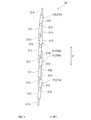
- FIG. 1 is a diagram schematically illustrating a state in which the shutter device according to the first embodiment is provided in a vehicle.
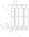
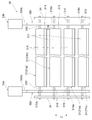
- FIG. 2 is a diagram illustrating the structure of the shutter device according to the first embodiment.
- FIG. 3 is a diagram illustrating the structure of the shutter device according to the first embodiment.
- FIG. 4 is a diagram schematically illustrating a state in which the shutter device according to the first embodiment is provided in the vehicle.
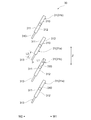
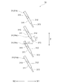
- FIG. 5 is a diagram for explaining the operation of the fin according to the first embodiment.
- FIG. 6 is a view for explaining the operation of the fin according to the first embodiment.
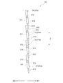
- FIG. 7 is a view for explaining the operation of the fin according to the first embodiment.
- FIG. 8 is a diagram for explaining the operation of the fin according to the first embodiment.
- FIG. 1 is a diagram schematically illustrating a state in which the shutter device according to the first embodiment is provided in a vehicle.
- FIG. 2 is a diagram illustrating the structure of the shutter device according to the first embodiment.
- FIG. 9 is a view for explaining the operation of the fin according to the first embodiment.
- FIG. 10 is a flowchart showing a flow of processing executed by the control unit according to the first embodiment.
- FIG. 11 is a flowchart showing a flow of processing executed by the control unit according to the first embodiment.
- FIG. 12 is a diagram for explaining the operation of the fin according to the first embodiment.
- FIG. 13 is a flowchart illustrating a flow of processing executed by the control unit according to the first embodiment.
- FIG. 14 is a diagram for explaining the operation of the fin according to the first embodiment.
- FIG. 15 is a diagram illustrating the structure of the shutter device according to the second embodiment.
- FIG. 16 is a view for explaining the operation of the fin according to the second embodiment.
- FIG. 15 is a diagram illustrating the structure of the shutter device according to the second embodiment.
- FIG. 17 is a diagram for explaining the operation of the fin according to the second embodiment.
- FIG. 18 is a flowchart illustrating a flow of processing executed by the control unit according to the second embodiment.
- FIG. 19 is a diagram for explaining the operation of the fin according to the second embodiment.
- FIG. 20 is a diagram schematically showing the structure of the fin according to the third embodiment.
- a shutter device 30 according to the present embodiment is a device mounted on the vehicle 10 and is a device for adjusting the flow of air flowing into the engine room 13 of the vehicle 10.
- FIG. 1 schematically shows an internal state of the front portion of the vehicle 10 in a top view.
- a grill opening 11 is formed on the front side of the vehicle 10 (left side in FIG. 1).
- the grill opening 11 communicates the external space in front of the vehicle 10 and the engine room 13 in which the engine 12 of the vehicle 10 is disposed.
- an outdoor heat exchanger 20, a radiator 21, and a fan device 22 are sequentially provided from the grill opening 11 toward the engine 12.
- the outdoor heat exchanger 20 is a part of an air conditioner (the whole is not shown) of the vehicle 10, and is a heat exchanger for exchanging heat between the refrigerant flowing inside and the air flowing outside. is there.
- the outdoor heat exchanger 20 functions as a so-called evaporator during the heating operation, and functions as a so-called condenser during the cooling operation.
- the structure of the air conditioning apparatus containing the outdoor heat exchanger 20 is known, the detailed description is omitted.
- the radiator 21 is a heat exchanger for exchanging heat between the cooling water flowing inside and the air flowing outside.
- the radiator 21 is supplied with cooling water that has passed through the engine 12 and has reached a high temperature.
- the cooling water is supplied to the engine 12 again after its temperature is lowered when passing through the radiator 21.
- the fan device 22 is a device for creating a flow of air that passes through the outdoor heat exchanger 20 and the radiator 21.
- the fan device 22 can operate by switching the rotation direction between forward rotation and reverse rotation.
- air is blown in the direction indicated by the arrow W1 in the drawing, that is, in the direction from the grill opening 11 toward the engine room 13.
- the fan device 22 rotates in the reverse direction, air is blown in the direction indicated by the arrow W2 in the drawing, that is, the direction from the engine room 13 toward the grill opening 11.
- the operation mode in which the fan device 22 is rotating forward is also referred to as “forward blowing mode”, and the operation mode in which the fan device 22 is rotating in reverse is also referred to as “reverse blowing mode”.
- the direction indicated by the arrow W1 is also referred to as “forward direction W1”, and the direction indicated by the arrow W2 is also referred to as “reverse direction W2”.
- the shutter device 30 is disposed in the grill opening 11 of the vehicle 10.
- the shutter device 30 includes a fin 31, a power transmission unit 32, an actuator 33, and a control unit 40.
- the fins 31 are plate-like members, and a plurality of fins 31 are provided on the shutter device 30.
- the fins 31 are arranged so as to be arranged at equal intervals along the left-right direction of the vehicle 10 (up-down direction in FIG. 1) while being supported by a frame 34 (see FIG. 2) fixed to the grill opening 11. ing.
- Each fin 31 is formed so that the shape of the main surface thereof is substantially rectangular, and is arranged in a state in which the longitudinal direction is along the vertical direction (the depth direction in FIG. 1).
- the direction in which the plurality of fins 31 are arranged is indicated by an arrow Z.
- the direction indicated by the arrow Z is also referred to as “fin arrangement direction Z”.
- Each fin 31 has a rotating shaft 310 that protrudes along the longitudinal direction at a position that is a tip in the longitudinal direction. As shown in FIGS. 2 and 3, an external gear 315 is formed on the rotation shaft 310 of each fin 31. The external gears 315 of the plurality of fins 31 are arranged in a straight line in the fin arrangement direction Z.
- the rotation shaft 310 of each fin 31 is rotatably supported by the frame 34. With such a structure, each fin 31 can rotate around the rotation shaft 310. As the fins 31 rotate, the shutter device 30 is opened and closed.
- the plurality of fins 31 rotate around the rotation axis 310 along the longitudinal direction thereof, thereby allowing air to pass as shown in FIG. 1 (hereinafter also referred to as “open state”). 4 is configured to switch between a state where the air flow is blocked (hereinafter also referred to as “blocked state”) as shown in FIG.
- the “rotation axis” here may be an axis that becomes a rotation center when the fin 31 rotates, and may be a virtual axis instead of a tangible axis as in the present embodiment. .
- two protrusions are formed at the end of the fin 31 in the longitudinal direction, and a virtual rotation axis that is the center of rotation is set at a position between these protrusions. May be.
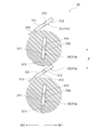
- each fin 31 is provided with a seal member 313.
- the seal member 313 is formed so as to extend outward from an end portion of the fin 31 in a direction perpendicular to the rotation shaft 310 (which can be said to be an end portion of the fin 31 in the short direction).
- the seal member 313 is formed of a flexible material, specifically, an elastomer.
- the material of the seal member 313 may be a material that can be easily deformed when subjected to an external force, and preferably a material having elasticity that returns to its original state when the external force is lost.
- the sealing member 313 and the fin 31 configured as described above are configured so that the sealing member 313 is provided at the end of the fin 31 by integrally forming the materials constituting the sealing member 313 and the fin 31 by, for example, two-color molding. Can do.
- Each fin 31 has a first wind receiving surface 311 and a second wind receiving surface 312.
- the first wind receiving surface 311 is a surface on one side of the fin 31 formed in a plate shape
- the second wind receiving surface 312 is the surface on the other side (that is, the opposite side).
- the first wind receiving surface 311 is a surface on which air flowing in the forward direction W1 hits in the blocked state.
- the 2nd wind receiving surface 312 is a surface where the air which flows into the reverse direction W2 hits in the interruption
- the seal member 313 provided on the adjacent fin 31 hits either the first wind receiving surface 311 or the second wind receiving surface 312. It will be in contact.
- the sealing member 313 provided on the fin 31 (first fin) has a length that can be brought into contact with the adjacent fin 31 (second fin) in the blocked state.
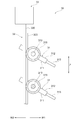
- the power transmission unit 32 is a member for transmitting a driving force of an actuator 33 described below to each fin 31 and rotating each fin 31. As shown in FIGS. 2 and 3, the power transmission unit 32 is formed to extend along the fin arrangement direction Z so as to face the external gears 315 of all the fins 31.
- the power transmission part 32 has a tooth part 320 that meshes with the external gear 315 of each fin 31 and constitutes a so-called rack and pinion.
- the actuator 33 is a device for rotating each fin 31 by moving the power transmission unit 32. As shown in FIGS. 2 and 3, the actuator 33 has a drive shaft 330 connected to one end of the power transmission unit 32. The actuator 33 moves the drive shaft 330 along the fin arrangement direction Z. When the power transmission unit 32 moves along with the drive shaft 330 along the fin arrangement direction Z, each fin 31 rotates around the rotation shaft 310.
- the actuator 33 is provided with a position sensor 41.
- the position sensor 41 detects the position of the drive shaft 330 in the fin arrangement direction Z and outputs a signal corresponding to the detected position of the drive shaft 330.
- the output signal of the position sensor 41 is input to the control unit 40 described later.
- the control unit 40 is a device for controlling the operation of the fan device 22 and the actuator 33.
- the control unit 40 is configured as a microcomputer having a storage device 400 and the like.
- the control unit 40 in the present embodiment is configured as a part of an ECU (Electronic Control Unit) that controls the vehicle 10. Instead of such a mode, the control unit 40 may be configured as a separate device from the ECU, and communication may be performed between the control unit 40 and the ECU.
- the control unit 40 controls the operation of the fan device 22, the actuator 33, and the like based on the traveling state of the vehicle 10, the driving state of the engine 12, the signal input from the position sensor 41, and the like.
- the control unit 40 normally keeps the fins 31 in an open state. Thereby, since the air ahead of the vehicle 10 can be supplied to the outdoor heat exchanger 20, the radiator 21, and the engine 12 by the traveling wind of the vehicle 10, the engine 12 can be cooled and the air conditioner can be Can work.
- control unit 40 operates the fan device 22 in the forward air blowing mode. Thereby, the air outside the vehicle 10 can be forcibly supplied to the outdoor heat exchanger 20, the radiator 21, and the engine 12.
- the control unit 40 puts the fins 31 into a cut-off state when the vehicle 10 is traveling in a high speed range, for example. Thereby, since the flow rate of the air flowing into the engine room 13 is limited, the aerodynamic performance of the vehicle can be improved.
- the control unit 40 puts the fins 31 into a shut-off state.
- the air heated in the engine room 13 during traveling of the vehicle 10 becomes difficult to escape to the outside of the vehicle 10, so that the inside of the engine room 13 can be kept warm.
- the engine 12 can be started in a high temperature state, so that an effect such as improvement in fuel consumption can be achieved.
- the control unit 40 puts the fins 31 into the cut-off state and operates the fan device 22 in the reverse air blowing mode. Thereby, the air heated in the engine 12 can be circulated in the engine room 13.
- first fin 31a one of the fins 31 adjacent to each other is referred to as a “first fin 31a” and the other is referred to as a “second fin 31b”.
- second fin 31b one of the fins 31 adjacent to each other is referred to as a “second fin 31b”.
- the following description of the “first fin 31a” and the “second fin 31b” is not applied only to the specific fin 31, but is applied to any of the plurality of fins 31. That is, hereinafter, the operations and states of the plurality of fins 31 will be described by describing the operations and states of the first fin 31a and the second fin 31b.
- the storage device 400 of the control unit 40 stores in advance the position of the drive shaft 330 corresponding to each posture of the fin 31 shown in each of FIGS.
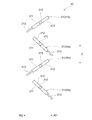
- front blocking posture The posture of the fin 31 shown in FIG. 5 is hereinafter referred to as “front blocking posture”.
- position of the drive shaft 330 in which all the fins 31 are in the front closing position is hereinafter referred to as “front blocking position”.
- the front blocking posture is one of the postures that the fins 31 can take in the shut-off state.
- the seal member 313 of the first fin 31a is in contact with the first wind receiving surface 311 which is the front surface of the second fin 31b.
- the front closing posture is a posture in which each sealing member 313 comes into contact with the adjacent fin 31 from the front side.
- first shut-off state The state shown in FIG. 5 among the shut-off states, that is, the state where the seal member 313 of the first fin 31a is in contact with the first wind receiving surface 311 of the second fin 31b is referred to as “first shut-off state” below. Is also referred to.
- the posture of the fin 31 shown in FIG. 6 is hereinafter referred to as a “front riding posture”.
- the position of the drive shaft 330 in which all the fins 31 are in the forward climbing posture is hereinafter referred to as “front climbing position”.
- the position of the seal member 313 of the first fin 31a is a position on the front side of the end of the second fin 31b in the vicinity thereof, It is in a state of being spaced apart. At this time, the distance L1 from the tip of the seal member 313 to the end of the second fin 31b is larger than the length L2 of the seal member 313.
- the posture of the fin 31 shown in FIG. 7 is hereinafter referred to as “rear closing posture”.
- the position of the drive shaft 330 in which all the fins 31 are in the backward closing posture is hereinafter referred to as “rear closing position”.
- the rear closing posture is one of the postures that the fins 31 can take in the shut-off state, like the front closing posture described above.
- the seal member 313 of the first fin 31a is in contact with the second wind receiving surface 312 which is the rear side surface of the second fin 31b. Yes.
- the rear closing posture is a posture in which each sealing member 313 comes into contact with the adjacent fin 31 from the rear side.
- shut-off state The state shown in FIG. 7 in the shut-off state, that is, the state in which the seal member 313 of the first fin 31a is in contact with the second wind receiving surface 312 of the second fin 31b is referred to as “second shut-off state” below. Is also referred to.
- backward riding posture The posture of the fin 31 shown in FIG. 8 is hereinafter referred to as “backward riding posture”.
- the position of the drive shaft 330 in which all the fins 31 are in the backward riding position is hereinafter referred to as “backward riding position”.
- the position of the seal member 313 of the first fin 31a is a position on the rear side from the end of the second fin 31b in the vicinity thereof, It is in a state of being spaced apart. At this time, the distance L1 from the tip of the seal member 313 to the end of the second fin 31b is larger than the length L2 of the seal member 313.
- the posture of the fin 31 shown in FIG. 9 is hereinafter referred to as “opening posture”.
- the position of the drive shaft 330 in which all the fins 31 are in the opening posture is hereinafter referred to as “opening position”.
- the opening posture is a posture that the fin 31 takes in the opening state.
- the first fin 31a and the second fin 31b are largely separated from each other, and air passes between the two.
- the control unit 40 controls the actuator 33 so that the position of the drive shaft 330 detected by the position sensor 41 becomes each position (such as a front closing position) stored in the storage device 400.
- the posture of the fin 31 is set to each posture shown in FIGS.
- control unit 40 repeatedly executes the process shown in FIG. 10 at a predetermined cycle.
- the control unit 40 first determines whether or not the operation mode of the fan device 22 is the reverse air blowing mode as the process of step S ⁇ b> 10.
- the control unit 40 makes a negative determination in the process of step S10, that is, when the fan device 22 is stopped, or when the operation mode of the fan device 22 is the forward air blowing mode, the process of step S11 is performed. Then, it is determined whether or not the target posture of the fin 31 is the opening posture.
- control unit 40 When the control unit 40 makes an affirmative determination in the process of step S11, that is, when the target posture of the fin 31 is the opening posture, the control unit 40 performs the opening control as the process of step S12.
- the opening control is control performed on the actuator 33 so that the posture of the fin 31 is maintained in the opening posture of FIG.
- step S11 determines whether or not the target posture of the fin 31 is the front closed posture or the rear closed posture
- the current posture of the fin 31 is processed as step S13. It is determined whether or not the vehicle is in the forward closed position.
- step S13 determines whether or not the vehicle is in the forward closed position.
- the control unit 40 executes the forward closing switching control as the process of step S14.
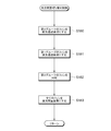
- the front blocking switching control is control for switching the posture of each fin 31 from the rear blocking posture to the front blocking posture. The specific procedure of the front block switching control is as shown in FIG.
- the control unit 40 first starts rotating the fins 31 in the direction from the backward closed posture (FIG. 7) to the overcoming posture (FIG. 6) as a process of step S ⁇ b> 140.
- the rotation direction of the fin 31 at this time is a clockwise direction in FIG. 7 and the like, and is a direction in which the seal member 313 provided on the first fin 31a is further pressed against the second fin 31b.
- FIG. 12 shows a state immediately before the seal member 313 is deformed as described above and gets over the second fin 31b.
- step S141 the control unit 40 displaces the fins 31 until the front position is reached (FIG. 6).
- the distance L1 from the tip of the seal member 313 to the end of the second fin 31b is greater than the length L2 of the seal member 313. For this reason, the seal member 313 provided on the first fin 31a is surely separated from the second fin 31b.
- control unit 40 rotates the fin 31 in the direction opposite to that in the process of step S142 and displaces it until the front closed position (FIG. 5) is reached.
- the control unit 40 has a direction in which the seal member 313 provided on the first fin 31a comes into contact with the second fin 31b from the opposite side (the second blocking state in FIG. 7).
- the control of rotating the plurality of fins 31 is performed.
- the control unit 40 executes the forward closing control as the process of step S15.
- the front closing control is control performed on the actuator 33 so that the posture of the fin 31 is maintained in the front closing posture of FIG.
- control unit 40 executes the forward closing control as the process of step S15 even when an affirmative determination is made in the processing of step S13, that is, when the current posture of the fin 31 is the forward closing posture.
- the control unit 40 makes an affirmative determination in the process of step S10, that is, when the operation mode of the fan device 22 is the reverse air blowing mode, as the process of step S16, the current posture of the fin 31 is the backward closed posture. It is determined whether or not.
- the control unit 40 executes the rear block switching control as the process of step S17.
- the rear block switching control is control for switching the posture of each fin 31 from the front closed posture to the rear closed posture. The specific procedure of the rear block switching control is as shown in FIG.
- the control unit 40 first rotates the fins 31 in the direction from the front closing posture (FIG. 5) to the rear riding posture (FIG. 8) as the process of step S ⁇ b> 170.
- the rotation direction of the fin 31 at this time is a counterclockwise direction in FIG. 5 and the like, and is a direction in which the seal member 313 provided on the first fin 31a is further pressed against the second fin 31b.
- the seal member 313 provided on the first fin 31a is deformed and gets over the second fin 31b.
- FIG. 14 shows a state immediately before the seal member 313 is deformed as described above and gets over the second fin 31b.
- step S171 the control unit 40 displaces the fin 31 until it assumes a rear riding posture (FIG. 8).
- the distance L1 from the tip of the seal member 313 to the end of the second fin 31b is greater than the length L2 of the seal member 313. For this reason, the seal member 313 provided on the first fin 31a is surely separated from the second fin 31b.
- control unit 40 rotates the fin 31 in the opposite direction to that in the process of step S172, and displaces it until the rear closed posture (FIG. 7) is reached.
- control unit 40 rotates the plurality of fins 31 in such a direction that the seal member 313 provided on the first fin 31a contacts the second fin 31b from the opposite side.
- control unit 40 executes the backward block control as the process of step S18.
- the rear closing control is control performed on the actuator 33 so that the posture of the fin 31 is maintained in the rear closing posture of FIG.
- control unit 40 executes the rear block control as the process of step S18 even when an affirmative determination is made in the process of step S16, that is, when the current posture of the fin 31 is the rear block position.
- the operation mode of the fan device 22 is not the reverse air blowing mode, that is, when the air flowing in the forward direction W1 hits the first air receiving surface 311 of the fin 31, the fin 31 Is set to the forward closing posture of FIG. 5, and the shutter device 30 is in the first blocking state.
- the seal member 313 of the first fin 31a is deformed by the force received from the air flowing in the forward direction W1, and is pressed against the first wind receiving surface 311 of the second fin 31b. Since the seal member 313 is in close contact with the first air receiving surface 311 and no gap is formed between them, the air flow passing through the fan device 22 is completely blocked. Moreover, since water does not enter between both, it is prevented that the water freezes and the fin 31 is fixed.
- the operation mode of the fan device 22 is the reverse air blowing mode, that is, when the air flowing in the reverse direction W2 hits the second air receiving surface 312 of the fin 31,
- the posture is set to the rear closing posture of FIG. 7, and the shutter device 30 is in the second blocking state.
- the seal member 313 of the first fin 31a is deformed by the force received from the air flowing in the reverse direction W2, and is pressed against the second wind receiving surface 312 of the second fin 31b. Since the seal member 313 is in close contact with the second air receiving surface 312 and there is no gap between them, the air flow passing through the fan device 22 is completely blocked. Moreover, since water does not enter between both, it is prevented that the water freezes and the fin 31 is fixed.
- the control unit 40 switches between the first blocking state (FIG. 5) and the second blocking state (FIG. 7) according to the air flow direction in the vicinity of the shutter device 30.
- the seal member 313 provided on the first fin 31a is pressed against the second fin 31b by the force received from the air, regardless of whether the air is flowing in the forward direction W1 or the reverse direction W2. It is assumed that This prevents a gap from being formed between the seal member 313 of the first fin 31a and the second fin 31b as described above.
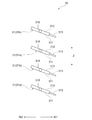
- the shutter device 30 of the present embodiment can rotate the adjacent first fin 31a and second fin 31b independently.
- the shutter device 30 includes two actuators 33a and 33b.
- the drive shaft 330a of the actuator 33a is provided with a power transmission unit 32a
- the drive shaft 330b of the actuator 33b is provided with a power transmission unit 32b.
- the control unit 40 can independently control the operation of the actuator 33a and the operation of the actuator 33b.
- the plurality of fins 31 are arranged so that the rotation shaft 310 having the external gear 315a and the center shaft having the external gear 315b are alternately arranged along the fin arrangement direction Z. ing.
- a tooth portion 320 (not shown) of the power transmission portion 32a meshes with the external gear 315a. Further, a tooth portion 320 (not shown) of the power transmission portion 32b is engaged with the external gear 315b.
- the plurality of fins 31 are divided into the first group having the external gear 315a and the second group having the external gear 315b, and the fins 31 belonging to each group are along the fin arrangement direction Z. They are arranged in an alternating fashion.
- the fins 31 belonging to the first group are driven by the actuator 33a, and the fins 31 belonging to the second group are driven by the actuator 33b.
- first fin 31a one of the adjacent fins 31 is referred to as “first fin 31a” and the other is referred to as “second fin 31b”.
- first fin 31a belongs to the first group
- second fin 31b belongs to the second group.
- the posture of the second fin 31b shown in FIG. 16 is hereinafter referred to as “forward retracted posture”.
- the position of the drive shaft 330b in which all the fins 31 belonging to the second group are in the forward retracted position is hereinafter referred to as “front retracted position”.
- a circular area indicated by hatching in FIG. 16 indicates a rotatable area of the first fin 31a.
- the posture of the first fin 31a shown in FIG. 17 is hereinafter referred to as a “retracting posture”.
- the position of the drive shaft 330a in which all the fins 31 belonging to the first group are in the backward retracted posture is hereinafter referred to as “rearward retracted position”.
- the seal member 313 of the first fin 31 a is located on the rear side of the rotation shaft 310.
- the entire first fin 31a is outside the rotatable region of the second fin 31b. For this reason, it is possible to freely rotate the second fin 31b without applying the seal member 313 or the like of the second fin 31b to the first fin 31a.
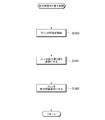
- the series of processing shown in FIG. 18 is executed in place of the series of processing shown in FIG. 13 as rear block switching control in the present embodiment.
- the control unit 40 rotates all the fins 31 belonging to the second group from the front closed position (FIG. 5) to the front retracted position (FIG. 16).
- the rotation direction of the fin 31 at this time is a clockwise direction in FIG. 16 and the like, and is a direction in which the seal member 313 provided on the second fin 31b moves away from the first fin 31a.
- each fin 31 is in the state shown in FIG.
- step S181 the control unit 40 rotates all the fins 31 belonging to the first group from the front closed position (FIG. 5) to the rearward retracted position (FIG. 17).
- the rotation direction of the fin 31 at this time is a counterclockwise direction in FIG.
- each fin 31 is in the state shown in FIG.
- step S182 the control unit 40 rotates all the fins 31 belonging to the second group in the counterclockwise direction so as to be parallel to the fins 31 belonging to the first group.
- each fin 31 is in the state shown in FIG. In this state, the seal member 313 provided on each fin 31 is located on the rear side of the rotation shaft 310.
- step S183 the control unit 40 rotates all the fins 31 in the clockwise direction and displaces them until the rearward closed posture (FIG. 7) is reached.
- each fin 31 changes from the front closing posture (FIG. 5) to the rear closing posture (FIG. 7)
- the seal member 313 provided in each fin 31 is It does not get over by being pressed against other fins 31.
- the control unit 40 operates the fins 31 belonging to the first group and the fins 31 belonging to the second group alternately so that the seal member 313 does not get over the fins 31.
- the shutter device 30 can be operated over a long period of time.
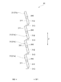
- seal members 313 and 314 are provided on each fin 31 in the present embodiment.
- the seal member 313 is formed so as to extend outward from one end of the fin 31 in the direction perpendicular to the rotation shaft 310 (also referred to as the end of the fin 31 in the short direction).
- the seal member 314 is formed to extend outward from the other end of the fin 31 in the direction perpendicular to the rotation shaft 310 (the end opposite to the one end).
- the sealing members are provided at both ends of the fin 31 in the direction perpendicular to the rotation shaft 310.
- the seal member 313 provided on the first fin 31a contacts the first air receiving surface 311 of the second fin 31b from the front side. ing. Further, the seal member 314 provided on the first fin 31a is in contact with the second wind receiving surface 312 of the second fin 31b from the rear side.
- the seal member 313 provided on the second fin 31b is in contact with the first wind receiving surface 311 of the first fin 31a from the front side. Further, the seal member 314 provided on the second fin 31b is in contact with the second wind receiving surface 312 of the first fin 31a from the rear side.
- the seal member 313 of the first fin 31a is deformed by the force received from the air flowing in the forward direction W1, and the second fin It will be pressed against the first wind receiving surface 311 of 31b. Further, the sealing member 313 of the second fin 31b is also deformed by the force received from the air flowing in the forward direction W1, and is pressed against the first wind receiving surface 311 of the first fin 31a. Since the seal member 313 is in close contact with the first wind receiving surface 311 and no gap is generated between them, the same effect as described in the first embodiment can be obtained.
- the seal member 314 of the first fin 31a is deformed by the force received from the air flowing in the reverse direction W2, and the second fin It will be pressed against the second wind receiving surface 312 of 31b. Further, the seal member 314 of the second fin 31b is also deformed by the force received from the air flowing in the reverse direction W2, and is pressed against the second wind receiving surface 312 of the first fin 31a. Since the seal member 313 is in close contact with the second wind receiving surface 312 and no gap is formed between them, the same effect as described in the first embodiment is obtained.
- the seal members 313 and 314 can always be brought into close contact with the fin 31 without rotating the fin 31 according to the air flow direction.
Landscapes
- Engineering & Computer Science (AREA)
- Mechanical Engineering (AREA)
- Chemical & Material Sciences (AREA)
- Combustion & Propulsion (AREA)
- Transportation (AREA)
- Cooling, Air Intake And Gas Exhaust, And Fuel Tank Arrangements In Propulsion Units (AREA)
Priority Applications (1)
| Application Number | Priority Date | Filing Date | Title |
|---|---|---|---|
| DE112018002246.3T DE112018002246T5 (de) | 2017-04-27 | 2018-03-29 | Blendenvorrichtung |
Applications Claiming Priority (2)
| Application Number | Priority Date | Filing Date | Title |
|---|---|---|---|
| JP2017088023A JP6696476B2 (ja) | 2017-04-27 | 2017-04-27 | シャッタ装置 |
| JP2017-088023 | 2017-04-27 |
Publications (1)
| Publication Number | Publication Date |
|---|---|
| WO2018198664A1 true WO2018198664A1 (ja) | 2018-11-01 |
Family
ID=63918315
Family Applications (1)
| Application Number | Title | Priority Date | Filing Date |
|---|---|---|---|
| PCT/JP2018/013377 Ceased WO2018198664A1 (ja) | 2017-04-27 | 2018-03-29 | シャッタ装置 |
Country Status (3)
| Country | Link |
|---|---|
| JP (1) | JP6696476B2 (enExample) |
| DE (1) | DE112018002246T5 (enExample) |
| WO (1) | WO2018198664A1 (enExample) |
Cited By (2)
| Publication number | Priority date | Publication date | Assignee | Title |
|---|---|---|---|---|
| CN111267604A (zh) * | 2020-03-24 | 2020-06-12 | 东风商用车有限公司 | 一种双自锁式可变进气格栅结构 |
| EP3725578A1 (fr) * | 2019-04-16 | 2020-10-21 | Flex-N-Gate France | Dispositif d'aération pour un véhicule, véhicule associé |
Families Citing this family (1)
| Publication number | Priority date | Publication date | Assignee | Title |
|---|---|---|---|---|
| JP7647932B2 (ja) * | 2021-12-07 | 2025-03-18 | 株式会社デンソー | シャッター装置 |
Citations (5)
| Publication number | Priority date | Publication date | Assignee | Title |
|---|---|---|---|---|
| JP2008106727A (ja) * | 2006-10-27 | 2008-05-08 | Honda Motor Co Ltd | 車両前部の空気取入装置 |
| JP2008260447A (ja) * | 2007-04-13 | 2008-10-30 | Mikuni Corp | ラジエータシャッター |
| US20120110909A1 (en) * | 2009-07-21 | 2012-05-10 | Magna International Inc. | Carrier with integrated ducting |
| JP2012224153A (ja) * | 2011-04-18 | 2012-11-15 | Toyota Motor Corp | 車両用シャッター装置 |
| JP2016135636A (ja) * | 2015-01-23 | 2016-07-28 | シロキ工業株式会社 | 車両用シャッター装置 |
Family Cites Families (2)
| Publication number | Priority date | Publication date | Assignee | Title |
|---|---|---|---|---|
| JP5919720B2 (ja) * | 2011-10-17 | 2016-05-18 | アイシン精機株式会社 | グリルシャッタ装置 |
| JP2013193603A (ja) * | 2012-03-21 | 2013-09-30 | Aisin Seiki Co Ltd | グリルシャッタ装置 |
-
2017
- 2017-04-27 JP JP2017088023A patent/JP6696476B2/ja not_active Expired - Fee Related
-
2018
- 2018-03-29 WO PCT/JP2018/013377 patent/WO2018198664A1/ja not_active Ceased
- 2018-03-29 DE DE112018002246.3T patent/DE112018002246T5/de not_active Ceased
Patent Citations (5)
| Publication number | Priority date | Publication date | Assignee | Title |
|---|---|---|---|---|
| JP2008106727A (ja) * | 2006-10-27 | 2008-05-08 | Honda Motor Co Ltd | 車両前部の空気取入装置 |
| JP2008260447A (ja) * | 2007-04-13 | 2008-10-30 | Mikuni Corp | ラジエータシャッター |
| US20120110909A1 (en) * | 2009-07-21 | 2012-05-10 | Magna International Inc. | Carrier with integrated ducting |
| JP2012224153A (ja) * | 2011-04-18 | 2012-11-15 | Toyota Motor Corp | 車両用シャッター装置 |
| JP2016135636A (ja) * | 2015-01-23 | 2016-07-28 | シロキ工業株式会社 | 車両用シャッター装置 |
Cited By (5)
| Publication number | Priority date | Publication date | Assignee | Title |
|---|---|---|---|---|
| EP3725578A1 (fr) * | 2019-04-16 | 2020-10-21 | Flex-N-Gate France | Dispositif d'aération pour un véhicule, véhicule associé |
| FR3095166A1 (fr) * | 2019-04-16 | 2020-10-23 | Flex-N-Gate France | Dispositif d’aération pour un véhicule, véhicule associé |
| US11364791B2 (en) | 2019-04-16 | 2022-06-21 | Flex-N-Gate France | Ventilation device for a vehicle, associated vehicle |
| CN111267604A (zh) * | 2020-03-24 | 2020-06-12 | 东风商用车有限公司 | 一种双自锁式可变进气格栅结构 |
| CN111267604B (zh) * | 2020-03-24 | 2024-12-03 | 东风商用车有限公司 | 一种双自锁式可变进气格栅结构 |
Also Published As
| Publication number | Publication date |
|---|---|
| JP6696476B2 (ja) | 2020-05-20 |
| JP2018184121A (ja) | 2018-11-22 |
| DE112018002246T5 (de) | 2020-01-16 |
Similar Documents
| Publication | Publication Date | Title |
|---|---|---|
| US10913332B2 (en) | Heat exchange unit | |
| US8919470B2 (en) | Grille shutter device | |
| EP3560744B1 (en) | Variable or stepped louver activation for active grille system | |
| US10369862B2 (en) | Air conditioning device | |
| WO2018198664A1 (ja) | シャッタ装置 | |
| US20170158019A1 (en) | Air conditioning device for vehicle | |
| JP6442961B2 (ja) | 車両用空調装置 | |
| US8893836B2 (en) | Grille shutter apparatus | |
| EP3626499B1 (en) | Vehicle front structure | |
| JP6658713B2 (ja) | 制御モジュール | |
| US10214095B2 (en) | Closure system, in particular for a motor vehicle | |
| JP2009068819A (ja) | 冷却装置 | |
| JP2009018643A (ja) | 車両用空調装置 | |
| JP2015183898A (ja) | 空気調和機 | |
| JP6150756B2 (ja) | ダンパの開閉機構および空気調和機器 | |
| US20170274726A1 (en) | Air conditioning apparatus for a vehicle | |
| JP6121056B2 (ja) | 車両用空気調和装置、それを備えた車両、及び、車両用空気調和装置の制御方法 | |
| JP7172154B2 (ja) | シャッター装置 | |
| CN116056924B (zh) | 车辆 | |
| JP6500806B2 (ja) | 車両用空気吹き出し装置 | |
| JP5506579B2 (ja) | 空気調和機の室内機 | |
| US12083859B2 (en) | Vehicular air conditioning system | |
| KR102109423B1 (ko) | 차량 엔진 룸 공기 유량 제어 시스템 및 그 제어 방법 | |
| JP5292979B2 (ja) | 電動アクチュエータシステム | |
| KR20080075631A (ko) | 차량용 공조장치 |
Legal Events
| Date | Code | Title | Description |
|---|---|---|---|
| 121 | Ep: the epo has been informed by wipo that ep was designated in this application |
Ref document number: 18792299 Country of ref document: EP Kind code of ref document: A1 |
|
| 122 | Ep: pct application non-entry in european phase |
Ref document number: 18792299 Country of ref document: EP Kind code of ref document: A1 |