WO2018190344A1 - リチウムイオン電池 - Google Patents
リチウムイオン電池 Download PDFInfo
- Publication number
- WO2018190344A1 WO2018190344A1 PCT/JP2018/015121 JP2018015121W WO2018190344A1 WO 2018190344 A1 WO2018190344 A1 WO 2018190344A1 JP 2018015121 W JP2018015121 W JP 2018015121W WO 2018190344 A1 WO2018190344 A1 WO 2018190344A1
- Authority
- WO
- WIPO (PCT)
- Prior art keywords
- positive electrode
- active material
- electrode active
- ion battery
- lithium ion
- Prior art date
- Legal status (The legal status is an assumption and is not a legal conclusion. Google has not performed a legal analysis and makes no representation as to the accuracy of the status listed.)
- Ceased
Links
Images




Classifications
-
- H—ELECTRICITY
- H01—ELECTRIC ELEMENTS
- H01M—PROCESSES OR MEANS, e.g. BATTERIES, FOR THE DIRECT CONVERSION OF CHEMICAL ENERGY INTO ELECTRICAL ENERGY
- H01M10/00—Secondary cells; Manufacture thereof
- H01M10/05—Accumulators with non-aqueous electrolyte
- H01M10/052—Li-accumulators
- H01M10/0525—Rocking-chair batteries, i.e. batteries with lithium insertion or intercalation in both electrodes; Lithium-ion batteries
-
- H—ELECTRICITY
- H01—ELECTRIC ELEMENTS
- H01M—PROCESSES OR MEANS, e.g. BATTERIES, FOR THE DIRECT CONVERSION OF CHEMICAL ENERGY INTO ELECTRICAL ENERGY
- H01M10/00—Secondary cells; Manufacture thereof
- H01M10/05—Accumulators with non-aqueous electrolyte
- H01M10/056—Accumulators with non-aqueous electrolyte characterised by the materials used as electrolytes, e.g. mixed inorganic/organic electrolytes
- H01M10/0564—Accumulators with non-aqueous electrolyte characterised by the materials used as electrolytes, e.g. mixed inorganic/organic electrolytes the electrolyte being constituted of organic materials only
- H01M10/0566—Liquid materials
-
- H—ELECTRICITY
- H01—ELECTRIC ELEMENTS
- H01M—PROCESSES OR MEANS, e.g. BATTERIES, FOR THE DIRECT CONVERSION OF CHEMICAL ENERGY INTO ELECTRICAL ENERGY
- H01M4/00—Electrodes
- H01M4/02—Electrodes composed of, or comprising, active material
- H01M4/13—Electrodes for accumulators with non-aqueous electrolyte, e.g. for lithium-accumulators; Processes of manufacture thereof
-
- H—ELECTRICITY
- H01—ELECTRIC ELEMENTS
- H01M—PROCESSES OR MEANS, e.g. BATTERIES, FOR THE DIRECT CONVERSION OF CHEMICAL ENERGY INTO ELECTRICAL ENERGY
- H01M4/00—Electrodes
- H01M4/02—Electrodes composed of, or comprising, active material
- H01M4/36—Selection of substances as active materials, active masses, active liquids
- H01M4/58—Selection of substances as active materials, active masses, active liquids of inorganic compounds other than oxides or hydroxides, e.g. sulfides, selenides, tellurides, halogenides or LiCoFy; of polyanionic structures, e.g. phosphates, silicates or borates
-
- H—ELECTRICITY
- H01—ELECTRIC ELEMENTS
- H01M—PROCESSES OR MEANS, e.g. BATTERIES, FOR THE DIRECT CONVERSION OF CHEMICAL ENERGY INTO ELECTRICAL ENERGY
- H01M4/00—Electrodes
- H01M4/02—Electrodes composed of, or comprising, active material
- H01M4/62—Selection of inactive substances as ingredients for active masses, e.g. binders, fillers
-
- Y—GENERAL TAGGING OF NEW TECHNOLOGICAL DEVELOPMENTS; GENERAL TAGGING OF CROSS-SECTIONAL TECHNOLOGIES SPANNING OVER SEVERAL SECTIONS OF THE IPC; TECHNICAL SUBJECTS COVERED BY FORMER USPC CROSS-REFERENCE ART COLLECTIONS [XRACs] AND DIGESTS
- Y02—TECHNOLOGIES OR APPLICATIONS FOR MITIGATION OR ADAPTATION AGAINST CLIMATE CHANGE
- Y02E—REDUCTION OF GREENHOUSE GAS [GHG] EMISSIONS, RELATED TO ENERGY GENERATION, TRANSMISSION OR DISTRIBUTION
- Y02E60/00—Enabling technologies; Technologies with a potential or indirect contribution to GHG emissions mitigation
- Y02E60/10—Energy storage using batteries
Definitions
- the present invention relates to a lithium ion battery, and more particularly to a lithium ion battery characterized by a positive electrode material of the lithium ion battery.
- Lithium ion batteries are known as chargeable / dischargeable secondary batteries. Lithium ion batteries are required to have a large capacity.
- Japanese Unexamined Patent Application Publication No. 2014-71965 discloses a lithium ion battery having a positive electrode active material made of a specific material.
- a positive electrode active material is selected from the viewpoint of increasing conductivity.
- An object of the present invention is to provide a lithium ion battery capable of increasing the capacity per unit volume.
- Lithium ion batteries are required to have a large capacity. Therefore, the inventors of the present application have examined a measure for increasing the capacity per unit volume. Specifically, the maximum utilization of the positive electrode active material having a large specific gravity was examined in detail. And it came to the knowledge that the average particle diameter of a positive electrode active material should just be enlarged. In other words, the inventors have come to know that a positive electrode active material that is not nano-sized may be used as the positive electrode active material.
- lithium ions come out of the positive electrode active material when charging and enter the positive electrode active material when discharged.
- lithium ion tends to come out from a positive electrode active material, it is hard to enter into a positive electrode active material.
- lithium ions are more difficult to enter the positive electrode active material. Therefore, when the average particle size of the positive electrode active material is increased, it is difficult to increase the capacity of the lithium ion battery.
- the inventors of the present application have further studied a measure for making lithium ions easily enter the positive electrode active material while using the positive electrode active material having a large average particle diameter.
- the present invention has been completed based on such findings.
- the electric capacity that can be taken out per unit volume is referred to as deemed capacity or specific capacity.
- the specific capacity varies depending on the power density of the lithium ion battery.
- the specific capacity of the lithium ion battery can be increased when the average particle diameter of the positive electrode active material is large. Therefore, even when the average particle diameter of the positive electrode active material is small, it is possible to increase the specific capacity of the lithium ion battery.
- the specific capacity of the lithium ion battery can be increased when a positive electrode active material that is not nano-sized is used. Therefore, even when a nano-sized positive electrode active material is used, it is possible to increase the specific capacity of the lithium ion battery.
- a lithium ion battery includes a positive electrode, a negative electrode, and an electrolytic solution.
- the electrolytic solution contains a lithium salt.
- the positive electrode and the negative electrode are in contact with the electrolytic solution.
- the positive electrode includes a positive electrode active material, a promoter, a conductive material, and a binder. Lithium ions present in the electrolytic solution are intercalated in the positive electrode active material.
- the promoter is dispersed together with the positive electrode active material and chemically reacts with the anion present in the electrolytic solution.
- the conductive material is present between the dispersed positive electrode active material and the promoter.
- the binder combines the positive electrode active material, the promoter, and the conductive material.
- the “lithium salt” is a reaction product in which hydrogen contained in an acid is replaced with lithium.
- the “lithium salt” is an ionic bond between an acid-derived anion and a base-derived lithium ion.
- the “electrolytic solution” is a solution in which an electrolyte is dissolved in a solvent.
- “intercalation” is a phenomenon in which molecules, atoms, or ions are inserted between layers in a substance having a layered structure or in a tunnel structure in a substance having a tunnel structure. .
- “Molecules, atoms, or ions are inserted into the tunnel structure” means, for example, that molecules, atoms, or ions are inserted into a space in the tunnel in the tunnel structure.
- “intercalation of lithium ions into the positive electrode active material” is a phenomenon in which lithium ions are inserted between layers in the positive electrode active material or in a tunnel structure in the positive electrode active material. .
- a molecule, atom, or ion inserted between layers in a substance having a layered structure or in a tunnel structure in a substance having a tunnel structure is expressed as “intercalating”.
- a positive electrode active material in which lithium ions present in the electrolytic solution intercalate refers to a layer between layers of the positive electrode active material or in a tunnel structure of the positive electrode active material. It is a positive electrode active material into which existing lithium ions are inserted.
- the substance having a tunnel structure is, for example, a positive electrode active material having an olivine structure.
- the lithium salt is separated into lithium ions and anions in the electrolytic solution. That is, in the lithium ion battery, lithium ions and anions exist in the electrolytic solution. As a result of the chemical reaction between the promoter and the anion, the amount of lithium ions in the electrolyte is greater than that of the anion. As a result, the balance between the number of lithium ions and the number of anions present around the positive electrode active material in the electrolytic solution, that is, the electrically neutral state in the electrolytic solution is lost.
- the electrically neutral state in the electrolytic solution is easily broken.
- the electrical neutral state is destroyed in the vicinity of the particles of the positive electrode active material.
- Lithium ions (Li ions) present in the vicinity of the particles of the positive electrode active material are intercalated to reduce the lithium cation concentration (Li cation concentration) in the vicinity of the particles.
- the accelerator reacts with the anion, and in the vicinity of the particle, the anion concentration becomes lower than the lithium cation concentration. It becomes easy to do. In the region on the negative electrode side beyond the separator, the electrically neutral state is not destroyed.
- lithium ions easily intercalate with the positive electrode active material in an attempt to return to the original electrically neutral state. Become. As a result, the capacity of the lithium ion battery can be increased.
- the positive electrode active material of the lithium ion battery when the average particle diameter of the positive electrode active material of the lithium ion battery is not nano-sized, the positive electrode active material having a large specific gravity can be utilized to the maximum. As a result, the capacity per unit volume can be increased.
- a material having an average particle size of nano-size may be used as the positive electrode active material of the lithium ion battery. Even when a positive electrode active material having an average particle size of nano-size is used, it is possible to increase the specific capacity of the lithium ion battery.
- the positive electrode active material is formed of an inorganic compound containing lithium.
- the positive electrode active material has, for example, an olivine structure.
- the positive electrode active material having an olivine structure may be, for example, lithium manganese phosphate (LiMnPO 4 ) or lithium iron phosphate (LiFePO 4 ).
- the positive electrode active material may be lithium manganese silicate (Li 2 MnSiO 4 ).
- As the positive electrode active material for example, two or more kinds of LiMnPO 4 , LiFePO 4, and Li 2 MnSiO 4 may be used. LiFePO 4 was once a nanomaterial, but the average particle size can be increased by carbon eutectoid, and in recent years, the size can be set to about 5 ⁇ m or more and 10 ⁇ m or less.
- D the diffusion coefficient of Li ions
- r the radius of Li ion particles
- t the time required to diffuse Li ions.
- the positive electrode active material is a nanomaterial
- the electron conductivity of the positive electrode is low.
- Electron conductivity is conductivity generated by the movement of electrons. If the electron conductivity is low, the movement of Li ions that react with electrons tends to be slow. Therefore, when an olivine compound material or the like closer to a nonconductor is used as the positive electrode active material than other material systems, the reaction between Li ions and electrons on the positive electrode surface tends not to occur. However, when the average particle size of the positive electrode active material is nano-sized, as described above, the movement of Li ions becomes faster, and the reaction between Li ions and electrons on the positive electrode surface is likely to occur. As a result, the capacity per unit volume can be increased.
- the average particle size of the positive electrode active material may be nano-sized or not nano-sized. However, if the average particle diameter of the positive electrode active material is not nano-sized, the specific capacity of the rechargeable ion battery can be increased. Since the nanomaterial is a small pulverized particle, the specific gravity (for example, tap specific gravity) is small. The tap specific gravity is measured by striking a container containing a powder of the positive electrode active material or filling it by vibrating. For example, when lithium cobalt oxide (LiCoO 2 ) is used as the positive electrode active material, the capacity per unit weight is 150 mAh / g, but the specific gravity of the non-nano-sized positive electrode active material is about 5 g / ml.
- LiCoO 2 lithium cobalt oxide
- the capacity per volume is 750 mAh / ml. Since batteries are limited in size, capacity per unit volume is important. If the positive electrode active material is a nanomaterial, the tap specific gravity is, for example, 0.1 g / ml or more and 0.3 g / ml or less, and thus the capacity per unit volume is small. When the average particle size of lithium cobalt oxide is nano-sized, the capacity per unit volume is, for example, 15 mAh / ml or more and 45 mAh / ml or less.
- the surface area per unit weight of the positive electrode active material that is not nano-sized is about 0.01 to 0.5 times the surface area per unit weight of the nano-size positive electrode active material.
- the surface area per unit weight is, for example, about 1 m 2 / g.
- the surface area per unit weight of the nano-sized positive electrode active material is, for example, several tens m 2 / g or more and 100 m 2 / g or less. Since the surface area per unit weight of the positive electrode active material is small, the reaction area of the positive electrode active material with the solvent of the electrolytic solution is also small.
- the reaction between the non-nanometer positive electrode active material and the electrolyte solution solvent is about 0.01 to 0.5 times the reaction between the nanosize cathode active material and the electrolyte solution solvent.
- the positive electrode active material reacts with the electrolyte solvent, impurities are generated and the solvent is altered, so that the cycle characteristics of the battery deteriorate.
- the positive electrode active material is not nano-sized, the cycle characteristics of the battery are high because the change in the solvent of the electrolytic solution is less than that when the positive electrode active material is nano-sized.
- the average particle diameter of the positive electrode active material is not nano-sized means that the average particle diameter of the positive electrode active material is 500 nm or more.
- the average particle diameter of the positive electrode active material not being nano-sized means that the average particle diameter of the positive electrode active material is larger than nano-size.
- the average particle diameter of the positive electrode active material being nano-sized means that the average particle diameter of the positive electrode active material is 1 nm or more and less than 500 nm.
- the average particle diameter of the positive electrode active material is preferably 5 ⁇ m or more and 20 ⁇ m or less.
- the average particle diameter is usually measured by a light scattering method, but is greatly affected by the aspect ratio and varies in value depending on the apparatus.
- the average particle diameter there is a method of obtaining an average diameter by creating a frequency distribution (histogram) of particle diameters measured with a scanning electron microscope.
- a cumulative distribution of particle diameters measured with a scanning electron microscope is created, and a median diameter with a cumulative degree of 50% is used.
- the average particle size of the promoter is not nano-sized. However, in the lithium ion battery, the average particle size of the promoter may be nano-sized. In the above lithium ion battery, the average particle size of the conductive material is nano-sized. However, in the lithium ion battery, the average particle size of the conductive material may not be nano-sized.
- the average particle diameter of the positive electrode active material may be larger than the average particle diameter of the promoter.
- the average particle diameter of the positive electrode active material may be larger than the average particle diameter of the conductive material.
- the average particle diameter of the positive electrode active material may be, for example, 2 to 10 times the average particle diameter of the promoter.
- the average particle diameter of the positive electrode active material may be, for example, 10 to 100 times the average particle diameter of the conductive material.
- the average particle diameter of the positive electrode active material may not be constant.
- a plurality of types of positive electrode active materials having different average particle diameters may be mixed. Specifically, a positive electrode active material having an average particle diameter of 5 ⁇ m and a positive electrode active material having an average particle diameter of 10 ⁇ m may be mixed.
- the particle shape of the positive electrode active material is not particularly limited.
- the particle shape of the positive electrode active material is preferably spherical.
- the proportion of the weight of the positive electrode active material in the positive electrode may be greater than the proportion of the weight of the promoter in the positive electrode.
- the weight ratio of the positive electrode active material in the positive electrode may be larger than the weight ratio of the conductive material in the positive electrode.
- the proportion of the weight of the positive electrode active material in the positive electrode is at least twice the proportion of the weight of the promoter in the positive electrode.
- the proportion of the weight of the positive electrode active material in the positive electrode may be 80 to 95 times the weight of the conductive material in the positive electrode, or may be more than 95 times.
- the promoter may be dispersed together with the positive electrode active material.
- the promoter is not particularly limited as long as it can chemically react with the anion present in the electrolytic solution. That is, the promoter is not particularly limited as long as it can destroy an electrically neutral state in the electrolytic solution.
- the promoter for example, at least one selected from a p-type semiconductor, a conductive polymer, and activated carbon can be used.
- the conductive polymer include polyaniline, 7,7,8,8-tetracyanoquinodimethane (TCNQ), 2,5-dimercapto-1,3,4-dithiazole, reduced ponianiline, and a conductive material. At least one selected from the added polypyrrole and the like can be used.
- the polypyrrole added with a conductive material is a material in which at least one of the substituents of the polypyrrole is a conductive material.
- a part of the promoter acts as a conductive material.
- the average particle size of the promoter may not be nano-sized or nano-sized.
- that the average particle diameter of the accelerator is not nano-size means that the average particle diameter of the accelerator is 500 nm or more. That the average particle diameter of a promoter is not nano size means that the average particle diameter of a promoter is larger than nano size. In this specification, that the average particle diameter of the promoter is nano-sized means that the average particle diameter of the promoter is 1 nm or more and less than 500 nm.
- the average particle diameter of the accelerator is preferably 0.5 ⁇ m or more and 20 ⁇ m or less. When the average particle size of the promoter is not nano-sized, the filling rate of the promoter is increased. This increases the capacity of the battery.
- the average particle size of the promoter may not be constant.
- a plurality of types of promoters having different average particle diameters may be mixed.
- the particle shape of the promoter is not particularly limited.
- the particle shape of the promoting material is, for example, a crushed solid material or a spherical shape.
- the conductive material is not particularly limited as long as it is present between the dispersed positive electrode active material and the promoter.
- the conductive material is not particularly limited as long as it forms a conductive path by contacting at least one of the positive electrode active material and the promoter.
- the conductive material may be, for example, carbon black or acetylene black which is a kind of carbon black. Carbon black exists as a minimum unit of aggregate (primary aggregate), and does not exist as a single particle (domain).
- the average particle size of the conductive material being nano-sized means that the average particle size of the particles (domains) is nano-sized.
- the average particle size of the aggregate (primary aggregate) may be larger than the nano size.
- the average particle size of the conductive material may be nano-sized or not nano-sized.
- the average particle diameter of the conductive material may be smaller than the average particle diameter of the positive electrode active material.
- the average particle diameter of the conductive material may be smaller than the average particle diameter of the promoter. In short, the conductive material only needs to be large enough to exist between the dispersed positive electrode active material and the promoter.
- the average particle diameter of the conductive material is, for example, 50 nm or more and less than 500 nm. In this specification, the average particle size of the conductive material being nano-sized means that the average particle size of the conductive material is 1 nm or more and less than 500 nm.
- the average particle size of the conductive material is not nano-sized means that the average particle size of the conductive material is 500 nm or more. That the average particle diameter of a conductive material is not nano-size means that the average particle diameter of a conductive material is larger than nano-size.
- the conductive material can easily exist between the positive electrode active material and the promoter.
- the proportion of the weight of the conductive material in the positive electrode is, for example, about 5% of the proportion of the weight of the positive electrode active material in the positive electrode.
- the surface area per unit weight of the conductive material is about 0.05 times the surface area per unit weight of the positive electrode active material. Therefore, the reaction area with the electrolyte solution of the nano-sized conductive material is much smaller than the reaction area with the electrolyte solution of the positive electrode active material that is not nano-sized. Therefore, even if the conductive material is nano-sized, it hardly affects the alteration of the solvent of the electrolytic solution.
- the binder is not particularly limited as long as it binds the positive electrode active material, the promoter, and the conductive material.
- the binder is, for example, polyvinylidene fluoride.
- the negative electrode includes a negative electrode active material.
- the negative electrode active material may contain carbon.
- the negative electrode active material may be, for example, graphite, soft carbon, hard carbon, or a combination thereof.
- the negative electrode active material may not contain carbon.
- the negative electrode active material is, for example, lithium titanate.
- the electrolytic solution is, for example, an organic electrolytic solution in which a lithium salt is dissolved in an organic solvent.
- the organic solvent is, for example, ethylene carbonate, propylene carbonate, dimethyl carbonate, diethyl carbonate, or ethyl methyl carbonate.
- the lithium salt include lithium hexafluorophosphate, lithium borofluoride, and lithium perchlorate.
- the electrolytic solution may be gelled by adding a polymer to the organic electrolytic solution. Examples of the polymer include polyethylene oxide, polypropylene oxide, and polyvinylidene fluoride.
- a lithium ion battery according to the present invention is a graph showing the charge characteristic and discharge characteristic of (positive electrode active material be a LiFePO 4).
- a lithium ion battery according to the present invention Example 2 is a graph showing the charge characteristic and discharge characteristic of (positive electrode active material be a LiFePO 4).
- Lithium-ion battery according to Comparative Example 1 is a graph showing the charge characteristic and discharge characteristic of (positive electrode active material be a LiFePO 4).
- Example 3 is a graph showing the charge characteristic and discharge characteristic of (positive electrode active material be a LiMnPO 4).
- Lithium-ion battery according to Comparative Example 2 is a graph showing the charge characteristic and discharge characteristic of (positive electrode active material be a LiMnPO 4).
- FIG. 1 is a model diagram of a lithium ion battery 10.
- the lithium ion battery 10 includes a positive electrode 12, a negative electrode 14, a separator 16, an electrolytic solution 18, and a case 20. Hereinafter, these will be described.
- the positive electrode 12 includes a current collector 121 and a film 122.
- the current collector 121 is made of aluminum.
- the film 122 covers the current collector 121. The details of the film 122 will be described later.
- the negative electrode 14 is disposed away from the positive electrode 12.
- the negative electrode 14 includes a current collector 141 and a film 142.
- the current collector 141 is made of aluminum.
- the film 142 covers the current collector 141.
- the film 142 includes a negative electrode active material.
- the negative electrode active material includes, for example, carbon.
- the separator 16 is disposed between the positive electrode 12 and the negative electrode 14.
- the separator 16 is a porous film.
- the separator 16 is made of, for example, polyethylene.
- the positive electrode 12, the negative electrode 14, and the separator 16 are immersed in the electrolytic solution 18.
- the electrolytic solution 18 is, for example, an organic electrolytic solution in which a lithium salt 182 is dissolved in an organic solvent 181. In the organic solvent 181, the lithium salt 182 is separated into lithium ions 1821 and anions 1822. That is, lithium ions 1821 and anions 1822 exist in the electrolytic solution 18.
- the case 20 accommodates the positive electrode 12, the negative electrode 14, the separator 16, and the electrolytic solution 18.
- the case 20 is, for example, a metal can.
- the shape of the case 20 is not particularly limited.
- the shape of the case 20 may be a cylindrical shape or a rectangular box shape.
- the film 122 includes a positive electrode active material 1221, a promoter 1222, a conductive material 1223, and a binder 1224.
- the positive electrode active material 1221 is formed of an inorganic compound containing lithium.
- the positive electrode active material 1221 has, for example, an olivine structure.
- the positive electrode active material 1221 having an olivine structure may be, for example, LiMnPO 4 or LiFePO 4 .
- the positive electrode active material 1221 may be Li 2 MnSiO 4 .
- As the positive electrode active material for example, two or more kinds of LiMnPO 4 , LiFePO 4 and Li 2 MnSiO 4 may be used.
- the average particle diameter of the positive electrode active material 1221 is, for example, 500 nm or more.
- the average particle diameter of the positive electrode active material 1221 is preferably 5 ⁇ m or more and 20 ⁇ m or less.
- the average particle diameter of the positive electrode active material 1221 may not be constant.
- a plurality of types of positive electrode active materials 1221 having different average particle diameters may be present in the film 122.
- the particle shape of the positive electrode active material 1221 is not particularly limited.
- the particle shape of the positive electrode active material 1221 is preferably spherical.
- the weight ratio of the positive electrode active material 1221 in the film 122 may be larger than the weight ratio of the promoter 1222 in the film 122.
- the weight ratio of the positive electrode active material 1221 in the film 122 may be larger than the weight ratio of the conductive material 1223 in the film 122.
- the proportion of the weight occupied by the positive electrode active material 1221 in the film 122 is, for example, 50% or more and 95% or less.
- the proportion of the weight occupied by the promoter 1222 in the film 122 is, for example, 5% or more and 50% or less.
- the ratio of the weight occupied by the conductive material 1223 in the film 122 is, for example, not less than 0.5% and not more than 10%.
- the accelerator 1222 is dispersed in the film 122 together with the positive electrode active material 1221.
- the promoter 1222 for example, at least one of a p-type semiconductor, a conductive polymer, and activated carbon can be used.
- the conductive polymer include polyaniline, 7,7,8,8-tetracyanoquinodimethane (TCNQ), 2,5-dimercapto-1,3,4-dithiazole, reduced ponianiline, and conductive material. At least one selected from polypyrrole added with can be used.
- the average particle diameter of the promoter 1222 is, for example, 500 nm or more.
- the average particle diameter of the accelerator 1222 is preferably 0.5 ⁇ m or more and 20 ⁇ m or less.
- the average particle size of the promoter 1222 may not be constant.
- a plurality of types of promoters having different average particle diameters may be present in the film 122.
- the particle shape of the promoter 1222 is not particularly limited.
- the particle shape of the promoter 1222 is, for example, a crushed lump or a sphere.
- Promoter 1222 chemically reacts with anion 1822 present in electrolyte 18.
- the promoting material 1222 chemically reacts with the anion 1822
- the lithium ion 1821 becomes larger than the anion 1822 in the electrolytic solution 18.
- the balance between the number of lithium ions 1821 and the number of anions 1822 present around the positive electrode active material 1221 in the electrolytic solution 18, that is, the electrically neutral state in the electrolytic solution 18 is lost.
- the electrically neutral state in the electrolytic solution 18 is broken, the lithium ions 1821 existing in the electrolytic solution 18 are easily intercalated into the positive electrode active material 1221. That is, the promoter 1222 promotes intercalation of the lithium ions 1821 into the positive electrode active material 1221.
- a chemical reaction between the anion 1822 and the promoter 1222 is more likely to occur than intercalation of the lithium ion 1821 into the positive electrode active material 1221.
- the conductive material 1223 exists between the positive electrode active material 1221 and the promoter 1222 dispersed in the film 122.
- the conductive material 1223 is in contact with at least one of the positive electrode active material 1221 and the promoter 1222 to form a conductive path in the film 122.
- the conductive material 1223 is, for example, carbon black.
- the conductive material 1223 may also exist between the positive electrode active material 1221 and the positive electrode active material 1221.
- the conductive material 1223 may exist between the promoting material 1222 and the promoting material 1222.
- the average particle diameter of the conductive material 1223 may be smaller than the average particle diameter of the positive electrode active material 1221.
- the average particle diameter of the conductive material 1223 may be smaller than the average particle diameter of the promoter 1222.
- the average particle size of the conductive material 1223 may be nano-sized or may not be nano-sized.
- the average particle diameter of the conductive material 1223 is, for example, not less than 50 nm and less than 500 nm.
- the binder 1224 combines the positive electrode active material 1221, the promoter 1222, and the conductive material 1223.
- the binder 1224 is, for example, polyvinylidene fluoride.
- lithium ions 1821 and anions 1822 exist in the electrolytic solution 18.
- the lithium ion 1821 becomes larger than the anion 1822 in the electrolytic solution 18.
- the balance between the number of lithium ions 1821 and the number of anions 1822 present around the positive electrode active material 1221 in the electrolytic solution 18, that is, the electrically neutral state in the electrolytic solution 18 is lost.
- the chemical reaction between the anion 1822 and the promoter 1222 is more likely to occur than the intercalation of the lithium ion 1821 into the positive electrode active material 1221. Therefore, in the lithium ion battery 10, it becomes easy to realize a state in which the electrically neutral state in the electrolytic solution 18 is broken. As a result, the lithium ions 1821 are easily intercalated into the positive electrode active material 1221, so that the capacity of the lithium ion battery 10 can be increased.
- the average particle diameter of the positive electrode active material 1221 is, for example, 500 nm or more. Therefore, the positive electrode active material 1221 formed of an inorganic compound having a large specific gravity can be used to the maximum extent. As a result, the capacity per unit volume of the lithium ion battery 10 can be increased.
- a lithium ion battery 10 (hereinafter sometimes referred to as a lithium ion battery according to an example of the present invention) was produced. Specifically, a lithium ion battery whose positive electrode active material is LiFePO 4 and a lithium ion battery whose positive electrode active material is LiMnPO 4 were prepared. The manufacturing method was as follows.
- LiFePO 4 Lithium ion battery whose positive electrode active material is LiFePO 4
- a positive electrode active material polytetrafluoroethylene (PTFE), polyaniline, and a mixture of conductive materials (mixture) were prepared.
- the weight ratio of the positive electrode active material to polyaniline was set to 0.9: 0.1 (hereinafter, such a mixture ratio is referred to as Example 1 of the present invention).
- the above mixture was put in a mortar and slowly crushed with a pestle while applying shear (shear pressure). Thereby, polytetrafluoroethylene gradually fibrillated, and the above mixture changed from powder to solid.
- the solidified mixture was sandwiched between SUS plates, and a pressure of 1 ton was applied by a hydraulic press.
- Example 2 The weight ratio of the positive electrode active material to polyaniline (hereinafter referred to as Example 2 of the present invention) and the positive electrode active material to polyaniline in a weight ratio of 0.8: 0.2.
- a disk-shaped positive electrode was obtained in the same manner with respect to those having a ratio of 1: 0 (hereinafter referred to as Comparative Example 1).
- the negative electrode was placed in an argon gas atmosphere.
- the negative electrode was a disc (diameter 14 mm) made of lithium. Between the positive electrode and the negative electrode, a glass filter paper punched into a circle having a diameter of 15 mm was sandwiched.
- An electrolytic solution (1 mL) was dropped to prepare a 2032 type coin cell.
- LiMnPO 4 Lithium ion battery whose positive electrode active material is LiMnPO 4
- the positive electrode active material in the same manner as the lithium-ion battery is LiMnPO 4 was prepared.
- the weight ratio of the positive electrode active material to polyaniline is 0.8: 0.2 (hereinafter, the mixture ratio is Inventive Example 3) and 1: 0 (hereinafter referred to as Comparative Example 2) were prepared.
- FIG. 2 The characteristics of the lithium ion battery will be described with reference to FIG. 2, FIG. 3, FIG. 4, FIG. 5, FIG.
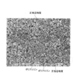
- FIG. 2 is a secondary electron image of an electron microscope on the surface of the positive electrode of the lithium ion battery according to Example 1 of the present invention.
- the secondary electron image of this electron microscope is an image acquired at an applied voltage of 20 kV and a magnification of 1000 times.
- each of the positive electrode active material and the polyaniline (promoter) is not nano-sized. Moreover, it turns out that a positive electrode active material is larger than polyaniline (promoter). Note that the conductive material is nano-sized.
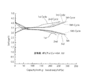
- FIG. 3 is a graph showing a curve indicating the charge characteristics and a curve indicating the discharge characteristics for the lithium ion battery according to Example 1 of the present invention.
- the curve indicating the charge characteristic and the curve indicating the discharge characteristic are respectively the case where the charge / discharge cycle is once, the case where it is two times, the case where it is three times, and the case where it is five times. The case of 10 times is shown. Charging and discharging were performed as follows.
- the lithium ion battery according to Example 1 of the present invention was charged by a constant current constant voltage method to obtain a curve indicating charging characteristics.
- the charging current in constant current charging was 1 mA.
- the charging voltage in constant voltage charging was 3.6V.
- the charge termination current was 0.1 mA.
- the lithium ion battery according to Example 1 of the present invention charged in this way was discharged at a constant current to obtain a curve showing the discharge characteristics.
- the discharge current was 1 mA.
- the final discharge voltage was 2.5V.
- FIG. 4 is a graph showing a curve indicating the charging characteristics and a curve indicating the discharge characteristics for the lithium ion battery according to Example 2 of the present invention.
- the curve which shows a charge characteristic and the curve which shows a discharge characteristic were obtained by the method similar to the case of the lithium ion battery which concerns on the example 1 of this invention.
- FIG. 5 is a graph showing a curve indicating the charging characteristics and a curve indicating the discharging characteristics for the lithium ion battery according to Comparative Example 1.
- the curve which shows a charge characteristic and the curve which shows a discharge characteristic were obtained by the method similar to the case of the lithium ion battery which concerns on the example 1 of this invention.
- Table 1 shows the discharge capacity at the 10th cycle of Invention Example 1, Invention Example 2 and Comparative Example 1.
- the discharge capacity shown in Table 1 is the discharge capacity per unit weight.
- the lithium ion battery according to Example 1 of the present invention and the lithium ion battery according to Example 2 of the present invention have a capacity higher than that of the lithium ion battery according to Comparative Example 1. Was able to be confirmed. Further, it was confirmed that the capacity of the lithium ion battery according to Invention Example 2 was larger than that of the lithium ion battery according to Invention Example 1.
- FIG. 6 is a graph showing a curve indicating the charging characteristics and a curve indicating the discharge characteristics for the lithium ion battery according to Example 3 of the present invention.
- the curve indicating the charge characteristic and the curve indicating the discharge characteristic are respectively the case where the charge / discharge cycle is once, the case where it is twice, the case where it is three times, and the case where it is four times, The case of 5 times is shown. Charging and discharging were performed as follows.
- the lithium ion battery according to Example 3 of the present invention was charged by a constant current constant voltage method to obtain a curve indicating charging characteristics.
- the charging current in constant current charging was 1 mA.
- the charging voltage in constant voltage charging was 4.5V.
- the charge termination current was 0.1 mA.
- the lithium ion battery according to Example 1 of the present invention charged in this way was discharged at a constant current to obtain a curve showing the discharge characteristics.
- the discharge current was 1 mA.
- the final discharge voltage was 2.5V.
- FIG. 7 is a graph showing a curve indicating charging characteristics and a curve indicating discharge characteristics for the lithium ion battery according to Comparative Example 2.
- the curve which shows a charge characteristic and the curve which shows a discharge characteristic were obtained with the method similar to the case of the lithium ion battery which concerns on the example 3 of this invention.
- Table 2 shows the discharge capacities of the fifth cycle of the present invention example 3 and the comparative example 2.
- the discharge capacity shown in Table 2 is the discharge capacity per unit weight.
Landscapes
- Chemical & Material Sciences (AREA)
- Chemical Kinetics & Catalysis (AREA)
- Electrochemistry (AREA)
- General Chemical & Material Sciences (AREA)
- Engineering & Computer Science (AREA)
- Manufacturing & Machinery (AREA)
- Inorganic Chemistry (AREA)
- Materials Engineering (AREA)
- Condensed Matter Physics & Semiconductors (AREA)
- General Physics & Mathematics (AREA)
- Physics & Mathematics (AREA)
- Battery Electrode And Active Subsutance (AREA)
- Secondary Cells (AREA)
Abstract
リチウムイオン電池は、正極と、負極と、電解液とを備える。電解液は、リチウム塩を含む。電解液には、正極及び負極が接触する。正極は、正極活物質と、促進材と、導電材と、バインダとを含む。正極活物質には、電解液中に存在するリチウムイオンがインターカレートする。促進材は、正極活物質とともに分散されて、電解液中に存在するアニオンと化学反応する。導電材は、分散された正極活物質と促進材との間に存在する。バインダは、正極活物質、促進材及び導電材を結合する。電解液中に存在するアニオンと促進材との化学反応は、電解液中に存在するリチウムイオンの正極活物質へのインターカレーションよりも発生し易い。
Description
本発明は、リチウムイオン電池に関し、詳しくは、リチウムイオン電池の正極材料に特徴を有するリチウムイオン電池に関する。
充放電可能な二次電池として、リチウムイオン電池が知られている。リチウムイオン電池は、容量を大きくすることが求められている。
例えば、特開2014-71965号公報には、特定の材料からなる正極活物質を有するリチウムイオン電池が開示されている。この公報では、導電性を高める観点から、正極活物質の材料を選定している。
本発明の目的は、単位体積当たりの容量を大きくすることができるリチウムイオン電池を提供することである。
リチウムイオン電池は、容量を大きくすることが求められている。そこで、本願の発明者等は、単位体積当たりの容量を大きくするための方策について検討をした。具体的には、比重の大きい正極活物質を最大限に利用することについて、詳細に検討した。そして、正極活物質の平均粒径を大きくすればよいとの知見を得るに至った。言い換えると、正極活物質として、ナノサイズではない正極活物質を使用すればよいとの知見を得るに至った。
リチウムイオン電池において、リチウムイオンは、充電するときに正極活物質から出てきて、放電するときに正極活物質に入る。ここで、リチウムイオンは、正極活物質から出ていき易いが、正極活物質に入り難い。加えて、正極活物質の平均粒径を大きくすると、リチウムイオンが正極活物質にさらに入り難くなる。そのため、正極活物質の平均粒径を大きくすると、リチウムイオン電池の容量を大きくすることが難しい。
そこで、本願の発明者等は、平均粒径の大きい正極活物質を用いつつ、リチウムイオンを正極活物質に入り易くするための方策についてさらに検討を進めた。その結果、電解液中で正極活物質の周囲に存在するリチウムイオンの数とアニオンの数とのバランス、つまり、電解液中での電気的に中性な状態をくずせばよいという新たな知見を得るに至った。本発明は、このような知見に基づいて、完成されたものである。単位体積当たりに取り出すことのできる電気容量は、みなし容量あるいは比容量と呼称される。比容量はリチウムイオン電池のパワー密度により変化する。本発明の知見に基づけば、正極活物質の平均粒径が大きい場合にリチイムイオン電池の比容量を大きくすることができる。そのため、正極活物質の平均粒径が小さい場合であっても、もちろんリチイムイオン電池の比容量を大きくすることができる。言い換えると、ナノサイズではない正極活物質を用いた場合にリチイムイオン電池の比容量を大きくすることができる。そのため、ナノサイズの正極活物質を用いた場合であっても、もちろんリチイムイオン電池の比容量を大きくすることができる。
本発明の実施の形態によるリチウムイオン電池は、正極と、負極と、電解液とを備える。電解液は、リチウム塩を含む。電解液には、正極及び負極が接触する。正極は、正極活物質と、促進材と、導電材と、バインダとを含む。正極活物質には、電解液中に存在するリチウムイオンがインターカレートする。促進材は、正極活物質とともに分散されて、電解液中に存在するアニオンと化学反応する。導電材は、分散された正極活物質と促進材との間に存在する。バインダは、正極活物質、促進材及び導電材を結合する。電解液中に存在するアニオンと促進材との化学反応は、電解液中に存在するリチウムイオンの正極活物質へのインターカレーションよりも発生し易い。
本発明において、「リチウム塩」とは、酸に含まれる水素をリチウムで置換した反応生成物である。具体的には、「リチウム塩」とは、酸由来のアニオンと塩基由来のリチウムイオンとがイオン結合したものである。本発明において、「電解液」とは、溶媒に電解質が溶解したものである。本発明において、「インターカレーション」とは、層状構造を有する物質における層と層の間、あるいは、トンネル構造を有する物質におけるトンネル構造中に、分子、原子、またはイオンが挿入される現象である。「トンネル構造中に、分子、原子、またはイオンが挿入される」とは、例えば、トンネル構造におけるトンネル内の空間に、分子、原子、またはイオンが挿入されることである。本発明において、「リチウムイオンの正極活物質へのインターカレーション」とは、正極活物質における層と層の間、あるいは、正極活物質におけるトンネル構造中に、リチウムイオンが挿入される現象である。本発明において、層状構造を有する物質における層と層の間、あるいは、トンネル構造を有する物質におけるトンネル構造中に、分子、原子、またはイオンが挿入されることを、「インタ-カレートする」と表現する。本発明において、「電解液中に存在するリチウムイオンがインターカレートする正極活物質」とは、正極活物質における層と層の間、あるいは、正極活物質におけるトンネル構造中に、電解液中に存在するリチウムイオンが挿入されるような正極活物質である。トンネル構造を有する物質は、例えば、オリビン構造を有する正極活物質である。
本発明において、「リチウム塩」とは、酸に含まれる水素をリチウムで置換した反応生成物である。具体的には、「リチウム塩」とは、酸由来のアニオンと塩基由来のリチウムイオンとがイオン結合したものである。本発明において、「電解液」とは、溶媒に電解質が溶解したものである。本発明において、「インターカレーション」とは、層状構造を有する物質における層と層の間、あるいは、トンネル構造を有する物質におけるトンネル構造中に、分子、原子、またはイオンが挿入される現象である。「トンネル構造中に、分子、原子、またはイオンが挿入される」とは、例えば、トンネル構造におけるトンネル内の空間に、分子、原子、またはイオンが挿入されることである。本発明において、「リチウムイオンの正極活物質へのインターカレーション」とは、正極活物質における層と層の間、あるいは、正極活物質におけるトンネル構造中に、リチウムイオンが挿入される現象である。本発明において、層状構造を有する物質における層と層の間、あるいは、トンネル構造を有する物質におけるトンネル構造中に、分子、原子、またはイオンが挿入されることを、「インタ-カレートする」と表現する。本発明において、「電解液中に存在するリチウムイオンがインターカレートする正極活物質」とは、正極活物質における層と層の間、あるいは、正極活物質におけるトンネル構造中に、電解液中に存在するリチウムイオンが挿入されるような正極活物質である。トンネル構造を有する物質は、例えば、オリビン構造を有する正極活物質である。
上記リチウムイオン電池において、リチウム塩は、電解液中で、リチウムイオンと、アニオンとに分離されている。つまり、上記リチウムイオン電池においては、電解液中に、リチウムイオンとアニオンとが存在する。促進材とアニオンとが化学反応することにより、電解液中において、リチウムイオンが、アニオンよりも多くなる。その結果、電解液中で正極活物質の周囲に存在するリチウムイオンの数とアニオンの数とのバランス、つまり、電解液中での電気的に中性な状態がくずれる。
上記リチウムイオン電池では、アニオンと促進材との化学反応が、リチウムイオンの正極活物質へのインターカレーションよりも発生し易い。そのため、電解液中での電気的に中性な状態がくずれ易い。ここで、電気的な中性な状態がくずれるのは、正極活物質の粒子の近傍である。正極活物質の粒子の近傍に存在するリチウムイオン(Liイオン)がインターカレートして、粒子近傍のリチウム陽イオン濃度(Li陽イオン濃度)が減少する。このとき、促進材が存在すると、促進材がアニオンと反応して、粒子近傍において、アニオン濃度がリチウム陽イオン濃度より低くなるので、電気的な中性な状態がくずれ、Liイオンがインターカレートし易くなる。セパレータを越えて負極側の領域においては電気的な中性な状態がくずれる訳ではない。
上記のように、電極近傍において電解液中での電気的に中性な状態がくずれると、元の電気的に中性な状態に戻ろうとして、リチウムイオンが正極活物質にインターカレートし易くなる。その結果、上記リチウムイオン電池においては、容量を大きくすることができる。
また、上記リチウムイオン電池の正極活物質の平均粒径がナノサイズではない場合、比重の大きい正極活物質を最大限に利用することができる。その結果、単位体積当たりの容量を大きくすることができる。ただし、上記リチイムイオン電池の正極活物質として平均粒径がナノサイズである材料を用いても良い。平均粒径がナノサイズである正極活物質を利用した場合でも、もちろんリチイムイオン電池の比容量を大きくすることができる。
正極活物質は、リチウムを含む無機化合物によって形成されている。正極活物質は、例えば、オリビン構造を有する。オリビン構造を有する正極活物質は、例えば、リン酸マンガンリチウム(LiMnPO4)であってもよいし、リン酸鉄リチウム(LiFePO4)であってもよい。正極活物質は、ケイ酸マンガンリチウム(Li2MnSiO4)であってもよい。正極活物質として、例えば、LiMnPO4、LiFePO4、およびLi2MnSiO4の2種類以上を用いてもよい。LiFePO4は、かつてはナノ材料であったが、カーボン共析することにより平均粒径を大きくすることができ、近年では5μm以上10μm以下程度の大きさとすることができる。
Liイオンの拡散係数をD、Liイオンの粒子の半径をr、Liイオンの拡散に要する時間をtとする。正極活物質がナノ材料であり、D=10-10cm2/sec、r=100nmとすると、r=2(Dt)1/2より、t=0.25secとなり、電池の反応速度としては十分となる。そのため、正極活物質として、他の材料系に比してより不導体に近いオリビン化合物材料などを用いる場合は、以下の理由により、正極活物質の平均粒径はナノサイズであることが好ましい。
正極活物質として、他の材料系に比してより不導体に近いオリビン化合物材料などを用いた場合、正極の電子伝導性が低い。電子伝導性とは、電子の移動によって生じる導電性である。電子伝導性が低いと、電子と反応するLiイオンの移動が遅くなりやすい。そのため、正極活物質として、他の材料系に比してより不導体に近いオリビン化合物材料などを用いた場合、正極表面におけるLiイオンと電子との反応が起きにくい傾向がある。ところが、正極活物質の平均粒径がナノサイズである場合、上述したように、Liイオンの移動が速くなるため、正極表面におけるLiイオンと電子との反応が起きやすくなる。その結果、単位体積当たりの容量を大きくすることができる。
正極活物質の平均粒径は、ナノサイズであってもよいし、ナノサイズでなくてもよい。ただし、正極活物質の平均粒径がナノサイズでなければ、リチイムイオン電池の比容量を大きくすることができる。ナノ材料は、小さく粉砕された粒子であるので、比重(例えばタップ比重)が小さい。タップ比重とは、正極活物質の紛体をいれた容器をたたいたり、振動させて充填したりして測定されるものである。例えば、正極活物質としてコバルト酸リチウム(LiCoO2)を用いた場合は、単位重量当たりの容量が150mAh/gであるが、ナノサイズでない正極活物質の比重が約5g/mlであるので、単位体積当たりの容量は750mAh/mlとなる。電池はサイズに制約があるため、単位体積当たりの容量は重要である。正極活物質がナノ材料であれば、タップ比重は、例えば、0.1g/ml以上0.3g/ml以下等であるので、単位体積当たりの容量は小さくなる。コバルト酸リチウムの平均粒径がナノサイズである場合、単位体積当たりの容量は、例えば、15mAh/ml以上45mAh/ml以下等である。
ナノサイズでない正極活物質の単位重量当たりの表面積は、ナノサイズである正極活物質の単位重量当たりの表面積の0.01倍から0.5倍程度である。例えば、平均粒径が5μm以上10μm以下のナノサイズでない正極活物質の場合、単位重量当たりの表面積は例えば1m2/g程度である。一方、ナノサイズである正極活物質の単位重量当たりの表面積は、例えば数十m2/g以上100m2/g以下である。正極活物質の単位重量当たりの表面積が小さいことにより、正極活物質の電解液の溶媒との反応面積も小さくなる。そのため、ナノサイズでない正極活物質と電解液の溶媒との反応は、ナノサイズである正極活物質と電解液の溶媒との反応の0.01倍から0.5倍程度である。正極活物質が電解質の溶媒と反応した場合、不純物が生成されて溶媒が変質するため、電池のサイクル特性が低下する。正極活物質がナノサイズでない場合、正極活物質がナノサイズである場合と比べて、電解液の溶媒の変質が少ないため、電池のサイクル特性が高い。
本明細書において、正極活物質の平均粒径がナノサイズでないとは、正極活物質の平均粒径が500nm以上であることをいう。正極活物質の平均粒径がナノサイズでないとは、正極活物質の平均粒径がナノサイズより大きいことをいう。本明細書において、正極活物質の平均粒径がナノサイズであるとは、正極活物質の平均粒径が1nm以上500nm未満であることをいう。
正極活物質の平均粒径は、好ましくは、5μm以上20μm以下である。平均粒径は、通常は光散乱法により測定するが、アスペクト比の影響を大きく受ける上、装置によって値にばらつきが生じる。そこで、走査型電子顕微鏡(SEM:Scanning Electron Microscope)を併用して実際の大きさを測定することが好ましい。平均粒径は、走査型電子顕微鏡で測定した粒子径の頻度分布(ヒストグラム)を作成し、平均径を求める方法がある。あるいは、走査型電子顕微鏡で測定した粒子径の累積分布を作成し、累積度が50%となるメディアン径を用いる方法がある。
正極活物質の平均粒径は、好ましくは、5μm以上20μm以下である。平均粒径は、通常は光散乱法により測定するが、アスペクト比の影響を大きく受ける上、装置によって値にばらつきが生じる。そこで、走査型電子顕微鏡(SEM:Scanning Electron Microscope)を併用して実際の大きさを測定することが好ましい。平均粒径は、走査型電子顕微鏡で測定した粒子径の頻度分布(ヒストグラム)を作成し、平均径を求める方法がある。あるいは、走査型電子顕微鏡で測定した粒子径の累積分布を作成し、累積度が50%となるメディアン径を用いる方法がある。
また、上記リチイムイオン電池において、促進材の平均粒径はナノサイズではない。ただし、上記リチイムイオン電池において、促進材の平均粒径はナノサイズであってもよい。また、上記リチイムイオン電池において、導電材の平均粒径はナノサイズである。ただし、上記リチイムイオン電池において、導電材の平均粒径はナノサイズでなくてもよい。
正極活物質の平均粒径は、促進材の平均粒径より大きくてもよい。正極活物質の平均粒径は、導電材の平均粒径よりも大きくてもよい。正極活物質の平均粒径は、例えば、促進材の平均粒径の2倍以上10倍以下であってもよい。正極活物質の平均粒径は、例えば、導電材の平均粒径の10倍以上100倍以下であってもよい。
正極活物質の平均粒径は、一定でなくてもよい。例えば、平均粒径の異なる複数種類の正極活物質が混ぜ合わされていてもよい。具体的には、平均粒径が5μmの正極活物質と、平均粒径が10μmの正極活物質とが混在していてもよい。
正極活物質の粒子形状は、特に限定されない。正極活物質の粒子形状は、好ましくは、球状である。
正極において正極活物質が占める重量の割合は、正極において促進材が占める重量の割合より大きくてもよい。正極において正極活物質が占める重量の割合は、正極において導電材が示す重量の割合よりも大きくてもよい。例えば、正極において正極活物質が占める重量の割合は、正極において促進材が占める重量の割合の2倍以上である。例えば、正極において正極活物質が占める重量の割合は、正極において導電材が占める重量の割合の80倍以上95倍以下でもよく、95倍を上回ってもよい。
促進材は、正極活物質とともに分散されていればよい。促進材は、電解液中に存在するアニオンと化学反応するものであれば、特に限定されない。つまり、促進材は、電解液中での電気的に中性な状態をくずすことができるものであれば、特に限定されない。促進材としては、例えば、p型半導体、導電性高分子、および活性炭から選択される少なくとも1種類を用いることができる。導電性高分子としては、例えば、ポリアニリン、7,7,8,8-テトラシアノキノジメタン(TCNQ)、2,5-ジメルカプト-1,3,4-ジチアゾール、還元型ポニアニリン、および導電材を加えたポリピロールなどから選択される少なくとも1種類を用いることができる。なお、導電材を加えたポリピロールとは、ポリピロールの置換基の少なくとも1つが導電材となったものである。導電材を加えたポリピロールを促進材として使用した場合、促進材の一部が導電材として作用することになる。
促進材の平均粒径は、ナノサイズでなくてもよいし、ナノサイズであってもよい。本明細書において、促進材の平均粒径がナノサイズでないとは、促進材の平均粒径が500nm以上であることをいう。促進材の平均粒径がナノサイズでないとは、促進材の平均粒径がナノサイズより大きいことをいう。本明細書において、促進材の平均粒径がナノサイズであるとは、促進材の平均粒径が1nm以上500nm未満であることをいう。促進材の平均粒径は、好ましくは、0.5μm以上20μm以下である。促進材の平均粒径がナノサイズでないことにより、促進材の充填率が高くなる。これにより、電池の容量が大きくなる。
促進材の平均粒径は、一定でなくてもよい。例えば、平均粒径の異なる複数種類の促進材が混ぜ合わされていてもよい。
促進材の粒子形状は、特に限定されない。促進材の粒子形状は、例えば、破砕された固体物あるいは球形状である。
導電材は、分散された正極活物質と促進材との間に存在するものであれば、特に限定されない。導電材は、正極活物質および促進材の少なくとも一方と接することにより、導電経路を形成するものであれば、特に限定されない。導電材は、例えば、カーボンブラックでもよく、カーボンブラックの一種であるアセチレンブラックでもよい。カーボンブラックは、アグリゲート(一次凝集体)を最小単位として存在し、粒子(ドメイン)単体では存在しない。導電材がアグリゲートを形成する物質の場合、導電材の平均粒径がナノサイズであるとは、粒子(ドメイン)の平均粒径がナノサイズであることをいう。アグリゲート(一次凝集体)の平均粒径はナノサイズより大きくてもよい。
導電材の平均粒径は、ナノサイズであってもよいし、ナノサイズでなくてもよい。導電材の平均粒径は、正極活物質の平均粒径よりも小さくてもよい。導電材の平均粒径は、促進材の平均粒径よりも小さくてもよい。要するに、導電材は、分散された正極活物質と促進材との間に存在することができる程度の大きさであればよい。導電材の平均粒径は、例えば、50nm以上500nm未満である。
本明細書において、導電材の平均粒径がナノサイズであるとは、導電材の平均粒径が1nm以上500nm未満であることをいう。本明細書において、導電材の平均粒径がナノサイズでないとは、導電材の平均粒径が500nm以上であることをいう。導電材の平均粒径がナノサイズでないとは、導電材の平均粒径がナノサイズより大きいことをいう。
導電材の平均粒径がナノサイズであることにより、正極活物質と促進材との間に導電材を存在させやすい。
本明細書において、導電材の平均粒径がナノサイズであるとは、導電材の平均粒径が1nm以上500nm未満であることをいう。本明細書において、導電材の平均粒径がナノサイズでないとは、導電材の平均粒径が500nm以上であることをいう。導電材の平均粒径がナノサイズでないとは、導電材の平均粒径がナノサイズより大きいことをいう。
導電材の平均粒径がナノサイズであることにより、正極活物質と促進材との間に導電材を存在させやすい。
正極において導電材が占める重量の割合が、正極において正極活物質が占める重量の割合の例えば5%程度であるとする。導電材がナノサイズであって正極活物質がナノサイズでない場合、導電材の単位重量当たりの表面積は、正極活物質の単位重量当たりの表面積の0.05倍程度である。したがって、ナノサイズである導電材の電解液との反応面積は、ナノサイズでない正極活物質の電解液との反応面積より非常に小さい。そのため、導電材はナノサイズであっても、電解液の溶媒の変質に殆ど影響を及ぼさない。
バインダは、正極活物質、促進材及び導電材を結合するものであれば、特に限定されない。バインダは、例えば、ポリフッ化ビニリデンである。
負極は、負極活物質を含む。負極活物質は、炭素を含むものであってもよい。この場合、負極活物質は、例えば、黒鉛であってもよいし、ソフトカーボンであってもよいし、ハードカーボンであってもよく、これらの組み合わせであってもよい。負極活物質は、炭素を含まないものであってもよい。この場合、負極活物質は、例えば、チタン酸リチウムである。
電解液は、例えば、有機溶媒にリチウム塩を溶解させた有機電解液である。有機溶媒は、例えば、エチレンカーボネート、プロピレンカーボネート、ジメチルカーボネート、ジエチルカーボネート、エチルメチルカーボネートである。リチウム塩は、例えば、ヘキサフルオロリン酸リチウム、ホウフッ化リチウム、過塩素酸リチウムである。電解液は、上記の有機電解液に対して、ポリマーを加えることにより、ゲル化したものであってもよい。ポリマーは、例えば、ポリエチレンオキシド、ポリプロピレンオキシド、ポリフッ化ビニリデンである。
以下、図面を参照しながら、本発明の実施の形態について説明する。図中同一又は相当部分には同一符号を付してその部材についての説明は繰り返さない。
図1を参照しながら、リチウムイオン電池10について説明する。図1は、リチウムイオン電池10のモデル図である。
リチウムイオン電池10は、正極12と、負極14と、セパレータ16と、電解液18と、ケース20とを備える。以下、これらについて説明する。
正極12は、集電体121と、膜122とを含む。集電体121は、アルミニウムで形成されている。膜122は、集電体121を覆う。なお、膜122の詳細については、後述する。
負極14は、正極12から離れて配置されている。負極14は、集電体141と、膜142とを含む。集電体141は、アルミニウムで形成されている。膜142は、集電体141を覆う。膜142は、負極活物質を含む。負極活物質は、例えば、炭素を含む。
セパレータ16は、正極12と負極14との間に配置されている。セパレータ16は、多孔質膜である。セパレータ16は、例えば、ポリエチレンで形成されている。
電解液18には、正極12、負極14及びセパレータ16が浸漬されている。電解液18は、例えば、有機溶媒181にリチウム塩182を溶解させた有機電解液である。有機溶媒181中において、リチウム塩182は、リチウムイオン1821と、アニオン1822とに分離されている。つまり、電解液18中には、リチウムイオン1821と、アニオン1822とが存在する。
ケース20は、正極12、負極14、セパレータ16及び電解液18を収容する。ケース20は、例えば、金属製の缶である。ケース20の形状は、特に限定されない。ケース20の形状は、円筒形であってもよいし、矩形の箱形状であってもよい。
続いて、膜122の詳細について説明する。膜122は、正極活物質1221と、促進材1222と、導電材1223と、バインダ1224とを含む。
正極活物質1221は、リチウムを含む無機化合物によって形成されている。正極活物質1221は、例えば、オリビン構造を有する。オリビン構造を有する正極活物質1221は、例えば、LiMnPO4であってもよいし、LiFePO4であってもよい。正極活物質1221は、Li2MnSiO4であってもよい。正極活物質として、例えば、LiMnPO4、LiFePO4およびLi2MnSiO4の2種類以上を用いてもよい。
正極活物質1221の平均粒径は、例えば500nm以上である。正極活物質1221の平均粒径は、好ましくは、5μm以上20μm以下である。
正極活物質1221の平均粒径は、一定でなくてもよい。例えば、平均粒径が異なる複数種類の正極活物質1221が膜122中に存在していてもよい。
正極活物質1221の粒子形状は、特に限定されない。正極活物質1221の粒子形状は、好ましくは、球状である。
膜122において正極活物質1221が占める重量の割合は、膜122において促進材1222が占める重量の割合より大きくてもよい。膜122において正極活物質1221が占める重量の割合は、膜122において導電材1223が占める重量の割合よりも大きくてもよい。膜122において正極活物質1221が占める重量の割合は、例えば、50%以上95%以下である。膜122において促進材1222が占める重量の割合は、例えば、5%以上50%以下である。膜122において導電材1223が占める重量の割合は、例えば、0.5%以上10%以下である。
促進材1222は、正極活物質1221とともに、膜122中に分散されている。促進材1222としては、例えば、p型半導体、導電性高分子、および活性炭の少なくとも1種類以上を用いることができる。導電性高分子としては、例えば、ポリアニリン、7,7,8,8-テトラシアノキノジメタン(TCNQ)、2,5-ジメルカプト-1,3,4-ジチアゾール、還元型ポニアニリン、および、導電材を加えたポリピロールから選択される少なくとも1種類を用いることができる。
促進材1222の平均粒径は、例えば500nm以上である。促進材1222の平均粒径は、好ましくは、0.5μm以上20μm以下である。
促進材1222の平均粒径は、一定でなくてもよい。例えば、平均粒径が異なる複数種類の促進材が膜122中に存在していてもよい。
促進材1222の粒子形状は、特に限定されない。促進材1222の粒子形状は、例えば、破砕された塊状あるいは球形状である。
促進材1222は、電解液18中に存在するアニオン1822と化学反応する。促進材1222がアニオン1822と化学反応することにより、電解液18中において、リチウムイオン1821が、アニオン1822よりも多くなる。その結果、電解液18中で正極活物質1221の周囲に存在するリチウムイオン1821の数とアニオン1822の数とのバランス、つまり、電解液18中での電気的に中性な状態がくずれる。このように、電解液18中での電気的に中性な状態がくずれると、電解液18中に存在するリチウムイオン1821が正極活物質1221にインターカレートし易くなる。つまり、促進材1222は、リチウムイオン1821の正極活物質1221へのインターカレーションを促進する。アニオン1822と促進材1222との化学反応は、リチウムイオン1821の正極活物質1221へのインターカレーションよりも発生し易い。
導電材1223は、膜122中に分散された正極活物質1221と促進材1222との間に存在する。導電材1223は、正極活物質1221および促進材1222の少なくとも一方と接することにより、膜122中に導電経路を形成する。導電材1223は、例えば、カーボンブラックである。導電材1223は、正極活物質1221と正極活物質1221の間にも存在してもよい。導電材1223は、促進材1222と促進材1222の間に存在してもよい。
導電材1223の平均粒径は、正極活物質1221の平均粒径よりも小さくてもよい。導電材1223の平均粒径は、促進材1222の平均粒径よりも小さくてもよい。導電材1223の平均粒径は、ナノサイズであってもよいし、ナノサイズでなくてもよい。導電材1223の平均粒径は、例えば、50nm以上500nm未満である。
バインダ1224は、正極活物質1221、促進材1222及び導電材1223を結合する。バインダ1224は、例えば、ポリフッ化ビニリデンである。
リチウムイオン電池10においては、電解液18中に、リチウムイオン1821とアニオン1822とが存在する。促進材1222とアニオン1822とが化学反応することにより、電解液18中において、リチウムイオン1821が、アニオン1822よりも多くなる。その結果、電解液18中で正極活物質1221の周囲に存在するリチウムイオン1821の数とアニオン1822の数とのバランス、つまり、電解液18中での電気的に中性な状態がくずれる。
このような状態になると、電解液18の電気的な状態を中性に戻そうとする作用が働き、リチウムイオン1821の正極活物質1221に対するインターカレーションが促進される。その結果、リチウムイオン電池10の容量を大きくすることができる。
ここで、リチウムイオン電池10では、アニオン1822と促進材1222との化学反応が、リチウムイオン1821の正極活物質1221へのインターカレーションよりも発生し易くなっている。そのため、リチウムイオン電池10では、上記のような電解液18中での電気的に中性な状態がくずれた状態を実現し易くなる。その結果、リチウムイオン1821が正極活物質1221にインターカレートし易くなるので、リチウムイオン電池10の容量を大きくすることができる。
また、リチウムイオン電池10では、正極活物質1221の平均粒径が例えば500nm以上である。そのため、比重の大きい無機化合物で形成された正極活物質1221を最大限に利用することができる。その結果、リチウムイオン電池10の単位体積当たりの容量を大きくすることができる。
リチウムイオン電池10(以下、本発明例に係るリチウムイオン電池と称することがある)を作製した。具体的には、正極活物質がLiFePO4であるリチウムイオン電池と、正極活物質がLiMnPO4であるリチウムイオン電池とを作製した。作製方法は、以下のとおりであった。
[正極活物質がLiFePO4であるリチウムイオン電池]
先ず、正極活物質と、ポリテトラフルオロエチレン(PTFE)と、ポリアニリンと、導電材を混合したもの(混合物)を準備した。正極活物質とポリアニリンとの重量比は、0.9:0.1にした(以下、このような混合比率のものを、本発明例1と称する)。上記の混合物を乳鉢に入れて、シアー(せん断圧力)をかけながら、乳棒でゆっくりと粉砕した。これにより、ポリテトラフルオロエチレンが次第にフィブリル化し、上記の混合物が粉体から固体に変化した。固体化した混合物を、SUS板で挟み、油圧プレスにより、1トンの圧力を加えた。そして、混合物をポンチにより打抜いて、直径14mmの円板状の正極を得た。正極活物質とポリアニリンとの重量比を0.8:0.2にしたもの(以下、このような混合比率のものを、本発明例2と称する)と、正極活物質とポリアニリンとの重量比を1:0にしたもの(以下、このような混合比率のものを、比較例1と称する)とについても、同様な方法により、円板状の正極を得た。
先ず、正極活物質と、ポリテトラフルオロエチレン(PTFE)と、ポリアニリンと、導電材を混合したもの(混合物)を準備した。正極活物質とポリアニリンとの重量比は、0.9:0.1にした(以下、このような混合比率のものを、本発明例1と称する)。上記の混合物を乳鉢に入れて、シアー(せん断圧力)をかけながら、乳棒でゆっくりと粉砕した。これにより、ポリテトラフルオロエチレンが次第にフィブリル化し、上記の混合物が粉体から固体に変化した。固体化した混合物を、SUS板で挟み、油圧プレスにより、1トンの圧力を加えた。そして、混合物をポンチにより打抜いて、直径14mmの円板状の正極を得た。正極活物質とポリアニリンとの重量比を0.8:0.2にしたもの(以下、このような混合比率のものを、本発明例2と称する)と、正極活物質とポリアニリンとの重量比を1:0にしたもの(以下、このような混合比率のものを、比較例1と称する)とについても、同様な方法により、円板状の正極を得た。
続いて、アルゴンガス雰囲気中で、負極を配置した。負極は、リチウムで形成された円板(直径14mm)であった。正極と負極の間には、直径15mmの円状に打ち抜いたガラスろ紙を挟んだ。電解液を1mL滴下して、2032型のコインセルを作製した。電解液は、重量比が、炭酸エチレン(EC):炭酸ジエチル(DEC)=1:1の溶液に、六フッ化リン酸リチウム(LiPF6)を1M/kgとなるように調整したものであった。なお、1Mは、1mol/m3である。
[正極活物質がLiMnPO4であるリチウムイオン電池]
正極活物質がLiMnPO4であるリチウムイオン電池についても、正極活物質がLiMnPO4であるリチウムイオン電池と同様な方法により、作製した。なお、正極活物質がLiMnPO4であるリチウムイオン電池については、正極活物質とポリアニリンとの重量比を、0.8:0.2にしたもの(以下、このような混合比率のものを、本発明例3と称する)と、1:0にしたもの(以下、このような混合比率のものを、比較例2と称する)とについて、作製した。
正極活物質がLiMnPO4であるリチウムイオン電池についても、正極活物質がLiMnPO4であるリチウムイオン電池と同様な方法により、作製した。なお、正極活物質がLiMnPO4であるリチウムイオン電池については、正極活物質とポリアニリンとの重量比を、0.8:0.2にしたもの(以下、このような混合比率のものを、本発明例3と称する)と、1:0にしたもの(以下、このような混合比率のものを、比較例2と称する)とについて、作製した。
図2、図3、図4、図5、図6及び図7を参照しながら、上記のリチウムイオン電池の特性について説明する。
図2は、本発明例1に係るリチウムイオン電池の正極の表面の電子顕微鏡の二次電子像である。この電子顕微鏡の二次電子像は、印加電圧が20kVで、倍率が1000倍で取得された像である。
図2に示すように、正極活物質及びポリアニリン(促進材)の各々がナノサイズでないことがわかる。また、正極活物質がポリアニリン(促進材)よりも大きいことがわかる。なお、導電材はナノサイズである。
図3は、本発明例1に係るリチウムイオン電池について、充電特性を示す曲線と、放電特性を示す曲線とを併せて示すグラフである。充電特性を示す曲線と、放電特性を示す曲線とは、それぞれ、充放電のサイクルが1回である場合と、2回である場合と、3回である場合と、5回である場合と、10回である場合とを示している。充電及び放電は、以下のようにして行った。
先ず、本発明例1に係るリチウムイオン電池を、定電流定電圧方式で充電して、充電特性を示す曲線を得た。定電流充電での充電電流は、1mAとした。定電圧充電での充電電圧は、3.6Vとした。充電終止電流は、0.1mAとした。
このようにして充電した本発明例1に係るリチウムイオン電池を定電流放電して、放電特性を示す曲線を得た。放電電流は、1mAとした。放電終止電圧は、2.5Vとした。一般的なリチウムイオン電池は、材料にもよるが概ね2Vを下回ると負極に使用されている銅の溶出限界電位を超える。このため、放電終止電圧を2.5Vとした。
図4は、本発明例2に係るリチウムイオン電池について、充電特性を示す曲線と、放電特性を示す曲線とを併せて示すグラフである。本発明例2に係るリチウムイオン電池については、本発明例1に係るリチウムイオン電池の場合と同様な方法により、充電特性を示す曲線と、放電特性を示す曲線とを得た。
図5は、比較例1に係るリチウムイオン電池について、充電特性を示す曲線と、放電特性を示す曲線とを併せて示すグラフである。比較例1に係るリチウムイオン電池については、本発明例1に係るリチウムイオン電池の場合と同様な方法により、充電特性を示す曲線と、放電特性を示す曲線とを得た。
表1に、本発明例1、本発明例2および比較例1の10サイクル目の放電容量を示している。表1に示す放電容量は、単位重量当たりの放電容量である。
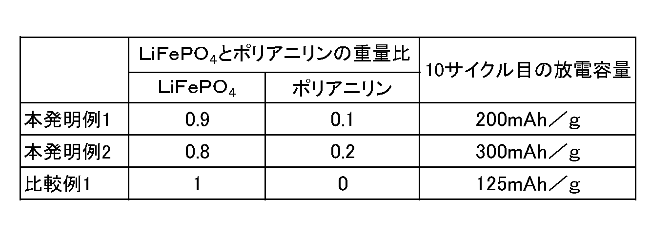
図3、図4、図5および表1に示すように、本発明例1に係るリチウムイオン電池及び本発明例2に係るリチウムイオン電池は、比較例1に係るリチウムイオン電池と比べて、容量が大きくなるのを確認できた。また、本発明例2に係るリチウムイオン電池は、本発明例1に係るリチウムイオン電池と比べて、容量が大きくなるのを確認できた。
図6は、本発明例3に係るリチウムイオン電池について、充電特性を示す曲線と、放電特性を示す曲線とを併せて示すグラフである。充電特性を示す曲線と、放電特性を示す曲線とは、それぞれ、充放電のサイクルが1回である場合と、2回である場合と、3回である場合と、4回である場合と、5回である場合とを示している。充電及び放電は、以下のようにして行った。
先ず、本発明例3に係るリチウムイオン電池を、定電流定電圧方式で充電して、充電特性を示す曲線を得た。定電流充電での充電電流は、1mAとした。定電圧充電での充電電圧は、4.5Vとした。充電終止電流は、0.1mAとした。
このようにして充電した本発明例1に係るリチウムイオン電池を定電流放電して、放電特性を示す曲線を得た。放電電流は、1mAとした。放電終止電圧は、2.5Vとした。
図7は、比較例2に係るリチウムイオン電池について、充電特性を示す曲線と、放電特性を示す曲線とを併せて示すグラフである。比較例2に係るリチウムイオン電池については、本発明例3に係るリチウムイオン電池の場合と同様な方法により、充電特性を示す曲線と、放電特性を示す曲線とを得た。
表2に、本発明例3および比較例2の5サイクル目の放電容量を示している。表2に示す放電容量は、単位重量当たりの放電容量である。
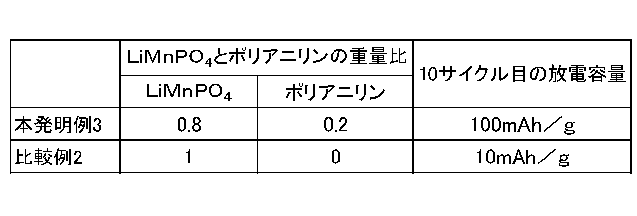
図6、図7および表2に示すように、本発明例3に係るリチウムイオン電池は、比較例2に係るリチウムイオン電池と比べて、容量が大きくなるのを確認できた。
以上、本発明の実施の形態を説明したが、上述した実施の形態は本発明を実施するための例示に過ぎない。よって、本発明は上述した実施の形態に限定されることなく、その趣旨を逸脱しない範囲内で上述した実施の形態を適宜変形して実施することが可能である。
10 リチウムイオン電池
12 正極
1221 正極活物質
1222 促進材
1223 導電材
1224 バインダ
14 負極
18 電解液
182 リチウム塩
1821 リチウムイオン
1822 アニオン
12 正極
1221 正極活物質
1222 促進材
1223 導電材
1224 バインダ
14 負極
18 電解液
182 リチウム塩
1821 リチウムイオン
1822 アニオン
Claims (8)
- リチウムイオン電池であって、
正極と、
負極と、
リチウム塩を含み、前記正極及び前記負極が接触する電解液とを備え、
前記正極は、
前記電解液中に存在するリチウムイオンがインターカレートする正極活物質と、
前記正極活物質とともに分散されて、前記電解液中に存在するアニオンと化学反応する促進材と、
分散された前記正極活物質と前記促進材との間に存在する導電材と、
前記正極活物質、前記促進材及び前記導電材を結合するバインダとを含み、
前記電解液中に存在するアニオンと前記促進材との化学反応は、前記電解液中に存在するリチウムイオンの前記正極活物質へのインターカレーションよりも発生し易い、リチウムイオン電池。 - 請求項1に記載のリチイムイオン電池であって、
前記正極活物質の平均粒径がナノサイズでない、リチイムイオン電池。 - 請求項1または請求項2に記載のリチイムイオン電池であって、
前記促進材の平均粒径がナノサイズでない、リチイムイオン電池。 - 請求項1ないし請求項3のいずれかに記載のリチイムイオン電池であって、
前記導電材の平均粒径がナノサイズである、リチイムイオン電池。 - 請求項1ないし請求項4のいずれかに記載のリチウムイオン電池であって、
前記正極活物質が、オリビン構造を有する、リチウムイオン電池。 - 請求項5に記載のリチウムイオン電池であって、
前記正極活物質が、LiMnPO4、LiFePO4及びLi2MnSiO4の何れかである、リチウムイオン電池。 - 請求項1ないし請求項6のいずれかに記載のリチウムイオン電池であって、
前記促進材が、導電性高分子である、リチウムイオン電池。 - 請求項7に記載のリチウムイオン電池であって、
前記促進材が、ポリアニリンである、リチウムイオン電池。
Priority Applications (2)
| Application Number | Priority Date | Filing Date | Title |
|---|---|---|---|
| JP2019512531A JP6820127B2 (ja) | 2017-04-11 | 2018-04-10 | リチウムイオン電池 |
| TW107112392A TW201840049A (zh) | 2017-04-11 | 2018-04-11 | 鋰離子電池 |
Applications Claiming Priority (2)
| Application Number | Priority Date | Filing Date | Title |
|---|---|---|---|
| JP2017078068 | 2017-04-11 | ||
| JP2017-078068 | 2017-04-11 |
Publications (1)
| Publication Number | Publication Date |
|---|---|
| WO2018190344A1 true WO2018190344A1 (ja) | 2018-10-18 |
Family
ID=63793402
Family Applications (1)
| Application Number | Title | Priority Date | Filing Date |
|---|---|---|---|
| PCT/JP2018/015121 Ceased WO2018190344A1 (ja) | 2017-04-11 | 2018-04-10 | リチウムイオン電池 |
Country Status (3)
| Country | Link |
|---|---|
| JP (1) | JP6820127B2 (ja) |
| TW (1) | TW201840049A (ja) |
| WO (1) | WO2018190344A1 (ja) |
Cited By (1)
| Publication number | Priority date | Publication date | Assignee | Title |
|---|---|---|---|---|
| JP2022514039A (ja) * | 2018-12-18 | 2022-02-09 | フラウンホーファー-ゲゼルシャフト ツゥア フェアデルング デア アンゲヴァンドテン フォァシュング エー.ファウ. | 固体電解質膜またはアノードの製造方法、並びに、固体電解質膜またはアノード |
Citations (2)
| Publication number | Priority date | Publication date | Assignee | Title |
|---|---|---|---|---|
| JP2015225753A (ja) * | 2014-05-27 | 2015-12-14 | 日東電工株式会社 | 蓄電デバイス |
| JP2017059550A (ja) * | 2016-12-28 | 2017-03-23 | 国立大学法人山形大学 | 正極及び非水電解質二次電池 |
Family Cites Families (6)
| Publication number | Priority date | Publication date | Assignee | Title |
|---|---|---|---|---|
| JP2005340165A (ja) * | 2004-03-23 | 2005-12-08 | Shirouma Science Co Ltd | リチウム二次電池用正極材料 |
| JP2013254585A (ja) * | 2012-06-05 | 2013-12-19 | Denso Corp | 非水電解液二次電池 |
| JP2014071965A (ja) * | 2012-09-28 | 2014-04-21 | Yamagata Univ | 電極及び非水電解質二次電池 |
| JP2016115435A (ja) * | 2014-12-11 | 2016-06-23 | 国立大学法人岩手大学 | リチウム二次電池用正極およびリチウム二次電池 |
| JP6570851B2 (ja) * | 2015-03-17 | 2019-09-04 | 古河機械金属株式会社 | バイポーラ型リチウムイオン電池およびバイポーラ型リチウムイオン電池の製造方法 |
| JP6465456B2 (ja) * | 2015-04-09 | 2019-02-06 | 株式会社Gsユアサ | 非水電解質二次電池用負極活物質、非水電解質二次電池用負極、及び非水電解質二次電池 |
-
2018
- 2018-04-10 JP JP2019512531A patent/JP6820127B2/ja not_active Expired - Fee Related
- 2018-04-10 WO PCT/JP2018/015121 patent/WO2018190344A1/ja not_active Ceased
- 2018-04-11 TW TW107112392A patent/TW201840049A/zh unknown
Patent Citations (2)
| Publication number | Priority date | Publication date | Assignee | Title |
|---|---|---|---|---|
| JP2015225753A (ja) * | 2014-05-27 | 2015-12-14 | 日東電工株式会社 | 蓄電デバイス |
| JP2017059550A (ja) * | 2016-12-28 | 2017-03-23 | 国立大学法人山形大学 | 正極及び非水電解質二次電池 |
Cited By (2)
| Publication number | Priority date | Publication date | Assignee | Title |
|---|---|---|---|---|
| JP2022514039A (ja) * | 2018-12-18 | 2022-02-09 | フラウンホーファー-ゲゼルシャフト ツゥア フェアデルング デア アンゲヴァンドテン フォァシュング エー.ファウ. | 固体電解質膜またはアノードの製造方法、並びに、固体電解質膜またはアノード |
| JP7557466B2 (ja) | 2018-12-18 | 2024-09-27 | フラウンホーファー-ゲゼルシャフト ツゥア フェアデルング デア アンゲヴァンドテン フォァシュング エー.ファウ. | 固体電解質膜またはアノードの製造方法、並びに、固体電解質膜またはアノード |
Also Published As
| Publication number | Publication date |
|---|---|
| JP6820127B2 (ja) | 2021-01-27 |
| TW201840049A (zh) | 2018-11-01 |
| JPWO2018190344A1 (ja) | 2019-11-21 |
Similar Documents
| Publication | Publication Date | Title |
|---|---|---|
| US11646443B2 (en) | Lithium solid battery | |
| Zhu et al. | Electrospun FeS2@ carbon fiber electrode as a high energy density cathode for rechargeable lithium batteries | |
| US10199646B2 (en) | Anodes for lithium-ion devices | |
| US9728776B2 (en) | Germanium-containing lithium-ion devices | |
| CN106605321B (zh) | 用于锂离子装置的负极 | |
| Liu et al. | Structural evolution of mesoporous graphene/LiNi1/3Co1/3Mn1/3O2 composite cathode for Li–ion battery | |
| US10756330B2 (en) | Porous silicon nanostructured electrode and method | |
| Ming et al. | Redox species-based electrolytes for advanced rechargeable lithium ion batteries | |
| Hwang et al. | Nano-compacted Li2S/Graphene composite cathode for high-energy lithium–sulfur batteries | |
| US20130157106A1 (en) | Lithium metal powder-carbon powder composite anode for lithium secondary battery and lithium metal secondary battery comprising the same | |
| CN114068924B (zh) | 负极活性物质及包含其的锂二次电池 | |
| Li et al. | Self-assembly of 2D sandwich-structured MnFe2O4/graphene composites for high-performance lithium storage | |
| Lakhdar et al. | Optimization of electrode and cell design for ultrafast-charging lithium-ion batteries based on molybdenum niobium oxide anodes | |
| JP6540741B2 (ja) | リチウム二次電池 | |
| Yuan et al. | Enhanced lithium storage performance in three-dimensional porous SnO2-Fe2O3 composite anode films | |
| Liu et al. | Closely compacted TiNb2O7-C assembly for fast-charging battery anodes | |
| Tan et al. | A novel Al@ TiO2-MCMB dual-ion battery with excellent cycling performance at high current rate | |
| US20220320512A1 (en) | All solid state battery | |
| JP6820127B2 (ja) | リチウムイオン電池 | |
| CN106486654A (zh) | 稳定化锂粉末和使用其的负极以及锂离子二次电池 | |
| KR102248668B1 (ko) | 고용량 알루미늄 이차전지 및 이의 제조 방법 | |
| US20240178388A1 (en) | Positive electrode and lithium-sulfur battery comprising the same | |
| KR20260074219A (ko) | 마이크론 및 서브마이크론 크기의 리튬철인산염 입자 및 이의 제조 방법 | |
| KR20250024090A (ko) | 부극 활물질 | |
| JPH09320606A (ja) | 非水電解質二次電池用電極の製造方法及び非水電解質二次電池 |
Legal Events
| Date | Code | Title | Description |
|---|---|---|---|
| 121 | Ep: the epo has been informed by wipo that ep was designated in this application |
Ref document number: 18784621 Country of ref document: EP Kind code of ref document: A1 |
|
| ENP | Entry into the national phase |
Ref document number: 2019512531 Country of ref document: JP Kind code of ref document: A |
|
| NENP | Non-entry into the national phase |
Ref country code: DE |
|
| 122 | Ep: pct application non-entry in european phase |
Ref document number: 18784621 Country of ref document: EP Kind code of ref document: A1 |