WO2018186371A1 - 高圧放電ランプ及びその制御方法 - Google Patents
高圧放電ランプ及びその制御方法 Download PDFInfo
- Publication number
- WO2018186371A1 WO2018186371A1 PCT/JP2018/014178 JP2018014178W WO2018186371A1 WO 2018186371 A1 WO2018186371 A1 WO 2018186371A1 JP 2018014178 W JP2018014178 W JP 2018014178W WO 2018186371 A1 WO2018186371 A1 WO 2018186371A1
- Authority
- WO
- WIPO (PCT)
- Prior art keywords
- resistors
- discharge lamp
- pressure discharge
- lamp
- arc tube
- Prior art date
- Legal status (The legal status is an assumption and is not a legal conclusion. Google has not performed a legal analysis and makes no representation as to the accuracy of the status listed.)
- Ceased
Links
Images




Classifications
-
- H—ELECTRICITY
- H05—ELECTRIC TECHNIQUES NOT OTHERWISE PROVIDED FOR
- H05B—ELECTRIC HEATING; ELECTRIC LIGHT SOURCES NOT OTHERWISE PROVIDED FOR; CIRCUIT ARRANGEMENTS FOR ELECTRIC LIGHT SOURCES, IN GENERAL
- H05B41/00—Circuit arrangements or apparatus for igniting or operating discharge lamps
- H05B41/14—Circuit arrangements
- H05B41/26—Circuit arrangements in which the lamp is fed by power derived from DC by means of a converter, e.g. by high-voltage DC
- H05B41/28—Circuit arrangements in which the lamp is fed by power derived from DC by means of a converter, e.g. by high-voltage DC using static converters
- H05B41/288—Circuit arrangements in which the lamp is fed by power derived from DC by means of a converter, e.g. by high-voltage DC using static converters with semiconductor devices and specially adapted for lamps without preheating electrodes, e.g. for high-intensity discharge lamps, high-pressure mercury or sodium lamps or low-pressure sodium lamps
- H05B41/2881—Load circuits; Control thereof
-
- H—ELECTRICITY
- H01—ELECTRIC ELEMENTS
- H01J—ELECTRIC DISCHARGE TUBES OR DISCHARGE LAMPS
- H01J61/00—Gas-discharge or vapour-discharge lamps
- H01J61/02—Details
- H01J61/025—Associated optical elements
-
- H—ELECTRICITY
- H01—ELECTRIC ELEMENTS
- H01J—ELECTRIC DISCHARGE TUBES OR DISCHARGE LAMPS
- H01J61/00—Gas-discharge or vapour-discharge lamps
- H01J61/02—Details
- H01J61/12—Selection of substances for gas fillings; Specified operating pressure or temperature
- H01J61/16—Selection of substances for gas fillings; Specified operating pressure or temperature having helium, argon, neon, krypton, or xenon as the principle constituent
-
- H—ELECTRICITY
- H05—ELECTRIC TECHNIQUES NOT OTHERWISE PROVIDED FOR
- H05B—ELECTRIC HEATING; ELECTRIC LIGHT SOURCES NOT OTHERWISE PROVIDED FOR; CIRCUIT ARRANGEMENTS FOR ELECTRIC LIGHT SOURCES, IN GENERAL
- H05B41/00—Circuit arrangements or apparatus for igniting or operating discharge lamps
- H05B41/14—Circuit arrangements
- H05B41/26—Circuit arrangements in which the lamp is fed by power derived from DC by means of a converter, e.g. by high-voltage DC
- H05B41/28—Circuit arrangements in which the lamp is fed by power derived from DC by means of a converter, e.g. by high-voltage DC using static converters
- H05B41/288—Circuit arrangements in which the lamp is fed by power derived from DC by means of a converter, e.g. by high-voltage DC using static converters with semiconductor devices and specially adapted for lamps without preheating electrodes, e.g. for high-intensity discharge lamps, high-pressure mercury or sodium lamps or low-pressure sodium lamps
Definitions
- the present invention relates to a high-pressure discharge lamp and a control method thereof, and more particularly, to a high-pressure discharge lamp and a control method thereof constituting a multi-light source part of an exposure apparatus.
- a conventional high-pressure discharge lamp 100 includes an arc tube 110 that discharges and emits light, a reflector 120 that emits light from the arc tube 110 with directivity, and an arc tube 110.
- An insulator 130 for fixing the reflector 120 and a wire 140 electrically connected to the arc tube 110 are mainly provided.
- a light emitting unit 111 having an internal space filled with halogen gas, mercury, starting argon, and the like, a pair of sealing units 112 and 113 for sealing the internal space of the light emitting unit 111, and light emission
- a pair of electrodes 114 and 115 are provided in the portion 111 so as to face each other.
- an incandescent lamp 131 is provided inside the insulator 130 so that whether or not the discharge lamp 100 is a genuine product can be inspected with high accuracy, in a short time, and at low cost.
- the present invention has been made in view of the above-described problems, and an object of the present invention is to provide a high-pressure discharge lamp capable of grasping the approximate usage time of the lamp by the lamp itself and a control method thereof.
- the above object of the present invention can be achieved by the following constitution.
- a high-pressure discharge lamp comprising:
- (2) The insulator has an open portion that communicates the space formed between the arc tube and the insertion hole of the reflector and the outside.
- the high-pressure discharge lamp according to (1) wherein the accommodating space in which the plurality of resistors are arranged is formed by the insulator on a side opposite to the reflector with respect to the open portion.
- a method for controlling a high-pressure discharge lamp according to (1) or (2) While monitoring the combined resistance value of the plurality of resistors, current is applied to the plurality of resistors so that the resistors are blown in order from the low resistance value, The method for controlling a high-pressure discharge lamp, wherein the applied current is stopped when the combined resistance value becomes large.
- a plurality of resistors having different resistance values are connected in parallel and arranged inside the insulator, so that the resistors are blown by checking the combined resistance value. It is possible to grasp the approximate usage time of the lamp by the lamp itself.
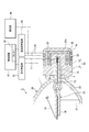
- FIG. 1 It is a perspective view of the high-pressure discharge lamp concerning one embodiment of the present invention. It is a side view of the high pressure discharge lamp shown in FIG. It is sectional drawing of the high pressure discharge lamp shown in FIG. It is a figure which shows the cross-sectional view which cut
- the high-pressure discharge lamp 1 of the present embodiment includes a glass arc tube 10 that discharges and emits light, a reflector 20 that emits light from the arc tube 10 with directivity, and Mainly provided is an insulator 30 for fixing the arc tube 10 and the reflector 20 respectively, and wires 16 and 17 (see FIG. 4) electrically connected to the arc tube 10.
- the arc tube 10 includes an ellipsoidal arc tube portion 13 in which a pair of electrodes 11 and 12 are arranged to face each other, and both ends of the arc tube portion 13 connected to each other. 11 and 12 and a pair of side tube portions 14 and 15 extending along the longitudinal axis X. Further, halogen gas, mercury, starting argon and the like are sealed in the inner space of the arc tube portion 13, and the pair of side tube portions 14 and 15 seal the internal space of the arc tube portion 13.
- the arc tube portion 13 may have a spherical shape.
- the reflector 20 is provided on one side in the longitudinal axis X direction, the opening 21 from which one side tube portion 14 projects, a parabolic reflecting surface 22 formed around the longitudinal axis X, and the longitudinal axis X. It is formed on the other side of the direction, and the other side tube portion 15 has an insertion hole 23 that can be inserted with a gap.
- the reflecting surface 22 of the reflector 20 is not limited to a parabolic shape, but may be an elliptical shape or a spherical shape. That is, the reflecting surface of the reflector of the present invention may be spherical or aspherical.
- the arc tube 10 has one electrode 11 extending into one side tube portion 14 as an anode (anode) and the other electrode 12 extending into the other side tube portion 15 as a cathode (cathode).
- the electric wires extending from the distal end portion of one side tube portion 14 and the proximal end portion of the other side tube portion 15 are respectively connected to a pair of wires 16 and 17 used for power feeding.
- the pair of wires 16 and 17 are connected to a lighting power source 35. Note that the wire 16 connected to the one side pipe portion 14 is led out to the outside through a cradle 24 attached to the reflector 20.
- the reflector 20 covers the base 31 of the insulator 30 on the outer side of the bowl-shaped bottom, and the joint is fixed with an adhesive (see FIG. 4).
- the cylindrical central portion of the base portion 31 of the insulator 30 includes a holding portion 32 that holds the proximal end portion of the other side tube portion 15 that is inserted into the insertion hole 23 of the reflector 20.
- the other side tube portion 15 is fixed to the insulator 30 and the adhesive by the holding portion 32. Therefore, the reflector 20 and the other side tube portion 15 of the arc tube 10 are respectively fixed to the insulator 30, and the reflector 20 and the arc tube 10 are not bonded, and the insertion hole of the other side tube portion 15 and the reflector 20 is inserted.
- the gap between 23 forms a space s.
- the insulator 30 includes the base portion 31 described above and a cover portion 33 that includes the holding portion 32 and covers the back of the base portion 31.
- the bottom 33a of the cover 33 is formed flat. For this reason, the lamp 1 may be fixed to the lamp holder 50 by bringing a lamp pressing cover (not shown) into contact with the flat bottom 33a and connecting the lamp pressing cover and the lamp holder 50 shown in FIG. .
- the base portion 31 of the insulator 30 communicates the space s between the other side tube portion 15 and the insertion hole 23 of the reflector 20 with the outside, and the other side tube portion 15 to the outside. It has two open parts 34 opened. Then, as shown in FIG. 5, when the lamp 1 is attached to the lamp holder 50, the air taken from the front of the lamp 1 is extracted from the space s by pulling and exhausting air behind the lamp holder 50. The arc tube 10 is cooled by passing through the opening 34. Therefore, the space s and the open part 34 form a cooling path.
- the outer edge of the opening 21 of the reflector 20 is formed in a substantially square shape with chamfered corners.
- One of the four corners is a notch 26 for alignment. It has a different shape.
- the lamp 1 is preferably aligned and attached to the lamp holder 50 so that the two open portions 34 formed in the insulator 30 are positioned in the vertical direction.
- the cooling efficiency may be further increased by making the shape of the insulator 30 asymmetric so that the opening area of the opening part 34 located on the upper side is larger than the opening area of the opening part 34 located on the lower side.
- the opening gap g of the opening 34 is defined by two planes passing through the longitudinal axis X, and the angle formed by the two planes is changed. The opening gap g and thus the opening area can be changed.
- the accommodation spaces Sp surrounded by the base portion 31 and the cover portion 33 of the insulator 30 have different resistance values and are connected in parallel.
- a plurality of (in this embodiment, two) resistors 37 and 38 are provided.
- the resistors 37 and 38 may be any one that generates a load when a current is passed, such as a filament of an incandescent lamp or a metal wire, a metal film resistor, a carbon resistor fuse, a bimetal, a thermocouple, or the like.
- resistors 37, 38 are connected to a resistor power source 39 via an external power supply wire 36, and are also connected to a measuring unit 40 that measures a current flowing through the power supply wire 36.
- the resistor power source 39 and the measuring unit 40 are connected to the control device 41 including the timer 42 together with the lighting power source 35 described above.
- the resistors 37 and 38 have the same material ( ⁇ : resistivity) and thickness (S: cross-sectional area), but have different lengths d1 and d2 (> d1), the resistors 37 and 38 are used.
- the resistance values R1 and R2 are R1 ⁇ R2.
- the resistors 37 and 38 start to melt when the Joule heat generated per unit volume exceeds a certain value. Since the cross-sectional area S is the same, as the Joule heat generated per unit volume, the resistor 37 is four times as large as the resistor 38, and the resistor 37 melts first and breaks. Therefore, when the lamp has been used for a predetermined time, a predetermined voltage is applied from the resistor power source 39, so that the resistors having lower resistance values are melted in order.
- the timer 42 built in the control device 41 monitors the lighting power source 35 to measure the usage time of the lamp 1. Then, when the usage time of the lamp 1 becomes the first predetermined time, the resistor 37 having a low resistance value is blown by applying the first predetermined voltage from the resistor power source 39. In addition, by applying a second predetermined voltage higher than the first predetermined voltage from the resistor power source 39 when the lamp 1 has been used for a second predetermined time longer than the first required time, The resistor 38 having a high resistance value is fused.
- the combined resistance value of these resistors 37 and 38 is grasped by measuring the current flowing through the feeding wire 36 by the measuring unit 40. Then, it is possible to confirm the approximate usage time of the lamp by checking which resistor 37, 38 is blown. Note that the resistance value of each resistor is measured in advance, and the relationship with the usage time is converted into data. Further, this data may be stored in the control device 41 as a table.
- control device 41 controls the voltage of the lighting power source 35 applied to the lamp 1 according to the usage time of the lamp 1, that is, the combined resistance value of the resistors 37 and 38 measured by the measuring unit 40.
- the resistors 37 and 38 may be not only voltage controlled but also current controlled or power controlled.
- the high-pressure discharge lamp 1 configured in this way is applied as a light source unit for an exposure apparatus by mounting a plurality of high-pressure discharge lamps 1 in the vertical and horizontal directions on the lamp holder 50. Therefore, by controlling the voltage applied to each lamp 1, it is possible to irradiate exposure light with uniform illuminance from each lamp 1.
- each lamp 1 can be cooled.
- the back side of the lamp holder 50 may constitute a sealed space in cooperation with the lamp pressing cover, and air may be exhausted from the sealed space.
- the plurality of resistors 37 and 38 having different resistance values are respectively connected in parallel and arranged inside the insulator 30.
- the combined resistance value it is possible to grasp whether or not the resistors 37 and 38 are blown, and it is possible to grasp the approximate usage time of the lamp by the lamp itself.
- the plurality of resistors 37 and 38 control the voltage applied to the resistor power source 39 so that the resistors 37 are blown in order from the resistor 37 having the lowest resistance value. Therefore, by checking the combined resistance value, it is possible to grasp whether or not the resistors 37 and 38 are blown, and it is possible to grasp the approximate usage time of the lamp itself.
- the voltage applied to the high-pressure discharge lamp 1 is controlled in accordance with the combined resistance value of the plurality of resistors 37 and 38, the exposure light with uniform illuminance is irradiated regardless of the usage time of the lamp 1. be able to.
- this invention is not limited to embodiment mentioned above, A deformation
- the method of connecting the arc tube and the wire and the configuration inside the arc tube are not limited to those of the present embodiment, and any conventional one can be applied.
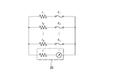
- the resistors ri have different resistance values, and the current values at which the fuse Fi is blown differ.
- each fuse Fi is disconnected each time a predetermined time elapses by flowing different currents from the resistor power source 39.
- r of the resistor power source 39 represents the internal resistance of the power source.
- the lifetime may be managed by controlling the voltage of the resistor power source 39 and sequentially cutting the fuses Fi.
- a plurality of resistors ri having different resistance values are arranged in parallel without providing the fuse Fi, and different currents are supplied from the resistor power source 39, whereby each resistor ri is predetermined. You may make it melt
- Example 1 In Example 1, two resistors having a resistor r1 made of a nichrome wire having a diameter of 0.2 mm and a length of 5 cm and a resistor r2 made of a nichrome wire having a diameter of 0.2 mm and a length of 10 cm were connected in parallel. A circuit was used. When a current was passed through the circuit, it was confirmed that only the resistor r1 having a length of about 4.5 A and a length of 5 cm could be melted.
- Example 2 In Example 2, a resistor r1 made of a nichrome wire having a diameter of 0.2 mm and a length of 3 cm, a resistor r2 made of a nichrome wire having a diameter of 0.3 mm and a length of 3 cm, and a nichrome having a diameter of 0.4 mm and a length of 3 cm. A circuit in which three resistors having a resistor r3 made of a line are connected in parallel was used. When a current was passed through the circuit, the resistor r3 began to heat red when 8A was passed, and the resistor r2 began to heat red at 10A and the resistor r1 started to heat red at 14A.
- the resistor r3 was melted, and the combined resistance value monitored increased rapidly. At this time, only the resistor r3 could be melted by stopping the current flow. That is, in this example, when an increase in the combined resistance value that is determined to be a blowout of the resistor is detected, the flow of current is temporarily stopped so that only one resistor is blown. Yes. Thereafter, it was confirmed that the resistor r2 and the resistor r1 could be melted in this order by increasing the current in the same manner.
- the present invention is based on a Japanese patent application (Japanese Patent Application No. 2017-074742) filed on April 4, 2017, the contents of which are incorporated herein by reference.
Landscapes
- Circuit Arrangements For Discharge Lamps (AREA)
- Non-Portable Lighting Devices Or Systems Thereof (AREA)
- Arrangement Of Elements, Cooling, Sealing, Or The Like Of Lighting Devices (AREA)
- Exposure And Positioning Against Photoresist Photosensitive Materials (AREA)
Abstract
Description
(1) 発光管と、
前記発光管の長手軸線周りに形成される球面状又は非球面状の反射面と、前記発光管が隙間を持って挿入可能な挿入孔と、を有するリフレクタと、
前記発光管と、前記リフレクタとがそれぞれ固定される碍子と、
前記碍子の内部に配置され、それぞれ異なる抵抗値を有し、それぞれ並列接続される複数の抵抗体と、
を備えることを特徴とする高圧放電ランプ。
(2) 前記碍子は、前記発光管と前記リフレクタの挿入孔との間に形成された空間と外部とを連通する開放部を有し、
前記複数の抵抗体が配置される収容空間は、前記開放部に対して、前記リフレクタと反対側で、前記碍子によって形成されることを特徴とする(1)に記載の高圧放電ランプ。
(3) (1)又は(2)に記載の高圧放電ランプの制御方法であって、
前記複数の抵抗体は、前記抵抗値が低い前記抵抗体から順に溶断するように前記抵抗体に印加する電圧を制御することを特徴とする高圧放電ランプの制御方法。
(4) 前記複数の抵抗体の合成抵抗値に応じて、前記高圧放電ランプへの印加電圧を制御することを特徴とする(3)に記載の高圧放電ランプの制御方法。
(5) (1)又は(2)に記載の高圧放電ランプの制御方法であって、
前記複数の抵抗体の合成抵抗値をモニターしながら、前記抵抗値が低い前記抵抗体から順に溶断するように前記複数の抵抗体に電流を印加し、
前記合成抵抗値が大きくなった時に、前記印加する電流を停止することを特徴とする高圧放電ランプの制御方法。
図1に示すように、本実施形態の高圧放電ランプ1は、放電し光を発光するガラス製の発光管10と、発光管10からの光に指向性を持たせて出射するリフレクタ20と、発光管10とリフレクタ20とをそれぞれ固定する碍子30と、発光管10と電気的に接続されるワイヤ16、17(図4参照)と、を主に備える。
したがって、リフレクタ20及び発光管10の他方の側管部15は、碍子30にそれぞれ固定され、リフレクタ20と発光管10とは接着されておらず、他方の側管部15とリフレクタ20の挿入孔23との間の隙間は、空間sを形成する。
このため、この平坦な底部33aに図示しないランプ押さえカバーを当接させ、このランプ押さえカバーと図5に示すランプホルダ50とを結合することで、ランプ1をランプホルダ50に固定してもよい。
このため、ランプホルダ50が組み込まれる照明装置において、碍子30に形成された2つの開放部34が上下方向に位置するように、ランプ1がアライメントされてランプホルダ50に取り付けられることが好ましい。
抵抗体37,38としては、白熱灯のフィラメントや金属ワイヤの他、金属皮膜抵抗、カーボン抵抗ヒューズ、バイメタル、熱電対等、電流を流したときに負荷を生じるものであればいずれでもよい。
なお、抵抗体用電源39及び測定部40は、上述した点灯用電源35と共に、タイマー42を内蔵した制御装置41に接続されている。
P1=V2/R1=V2/(ρd1/S)
P2=V2/R2=V2/(ρd2/S)
となる。
よって、P1/P2=R1/R2=d2/d1であるので、ジュール熱の比は、長さの比となる。
断面積Sは同じなので、単位体積当たりに発生するジュール熱としては、抵抗体37は、抵抗体38の4倍となり、抵抗体37が先に溶けて断線する。したがって、ランプの使用時間が所定時間となった時点で、抵抗体用電源39から所定の電圧を印加することで、抵抗値が低い抵抗体から順に溶断する。
なお、抵抗体37,38は、電圧制御だけでなく、電流制御や、電力制御であってもよい。
例えば、本発明では、発光管とワイヤとの接続の仕方や、発光管内部の構成は、本実施形態のものに限定されず、従来の任意のものを適用することができる。
また、抵抗体用電源39の電圧を制御して、各ヒューズFiを順に切断することで、寿命時間の管理を行うようにしてもよい。
さらに、すべての抵抗体riとヒューズFiの合成抵抗値を判定回路にて判定することにより、ランプ1の仕様を判別することが可能である。この場合、仕様の異なるランプ1を点灯させた状態においても、寿命管理が可能となり、正常、且つ安全に点灯することができる。
実施例1では、直径0.2mm、長さ5cmのニクロム線からなる抵抗体r1と、直径0.2mm、長さ10cmのニクロム線からなる抵抗体r2とを有する2つの抵抗体を並列接続した回路を用いた。そして、上記回路に電流を流したところ、約4.5Aで長さ5cmの抵抗体r1だけを溶断できることが確認された。
実施例2では、直径0.2mm、長さ3cmのニクロム線からなる抵抗体r1と、直径0.3mm、長さ3cmのニクロム線からなる抵抗体r2と、0.4mm、長さ3cmのニクロム線からなる抵抗体r3と、を有する3つの抵抗体を並列接続した回路を用いた。
そして、上記回路に電流を流したところ、8Aを流したところで、抵抗体r3が赤熱し始め、10Aで抵抗体r2が赤熱、14Aで抵抗体r1が赤熱し始めた。さらに、14Aで電流を流し続けたところ、抵抗体r3が溶断し、モニターしていた合成抵抗値が急激に大きくなった。このとき、電流を流すのを停止することで、抵抗体r3だけを溶断することができた。
即ち、この例では、抵抗体の溶断と判断される大きさの合成抵抗値の上昇が検知されたときに、電流を流すのを一旦停止して、1つの抵抗体だけを溶断させるようにしている。
その後、同様に、電流を上昇させていき、抵抗体r2、抵抗体r1を順に溶断できることが確認された。
10 発光管
11、12 電極
13 発光管部
14、15 側管部
20 リフレクタ
21 開口部
22 反射面
23 挿入孔
30 碍子
34 開放部
37、38、r1、r2、r3 抵抗体
41 制御装置
Sp 収容空間
Claims (5)
- 発光管と、
前記発光管の長手軸線周りに形成される球面状又は非球面状の反射面と、前記発光管が隙間を持って挿入可能な挿入孔と、を有するリフレクタと、
前記発光管と、前記リフレクタとがそれぞれ固定される碍子と、
前記碍子の内部に配置され、それぞれ異なる抵抗値を有し、それぞれ並列接続される複数の抵抗体と、
を備えることを特徴とする高圧放電ランプ。 - 前記碍子は、前記発光管と前記リフレクタの挿入孔との間に形成された空間と外部とを連通する開放部を有し、
前記複数の抵抗体が配置される収容空間は、前記開放部に対して、前記リフレクタと反対側で、前記碍子によって形成されることを特徴とする請求項1に記載の高圧放電ランプ。 - 請求項1又は2に記載の高圧放電ランプの制御方法であって、
前記複数の抵抗体は、前記抵抗値が低い前記抵抗体から順に溶断するように前記抵抗体に印加する電圧を制御することを特徴とする高圧放電ランプの制御方法。 - 前記複数の抵抗体の合成抵抗値に応じて、前記高圧放電ランプへの印加電圧を制御することを特徴とする請求項3に記載の高圧放電ランプの制御方法。
- 請求項1又は2に記載の高圧放電ランプの制御方法であって、
前記複数の抵抗体の合成抵抗値をモニターしながら、前記抵抗値が低い前記抵抗体から順に溶断するように前記複数の抵抗体に電流を印加し、
前記合成抵抗値が大きくなった時に、前記印加する電流を停止することを特徴とする高圧放電ランプの制御方法。
Priority Applications (3)
| Application Number | Priority Date | Filing Date | Title |
|---|---|---|---|
| KR1020197023476A KR20190134597A (ko) | 2017-04-04 | 2018-04-02 | 고압 방전 램프 및 그 제어 방법 |
| JP2019511245A JP7136467B2 (ja) | 2017-04-04 | 2018-04-02 | 高圧放電ランプ及びその制御方法 |
| CN201880023766.8A CN110547051B (zh) | 2017-04-04 | 2018-04-02 | 高压放电灯及其控制方法 |
Applications Claiming Priority (2)
| Application Number | Priority Date | Filing Date | Title |
|---|---|---|---|
| JP2017074742 | 2017-04-04 | ||
| JP2017-074742 | 2017-04-04 |
Publications (1)
| Publication Number | Publication Date |
|---|---|
| WO2018186371A1 true WO2018186371A1 (ja) | 2018-10-11 |
Family
ID=63712426
Family Applications (1)
| Application Number | Title | Priority Date | Filing Date |
|---|---|---|---|
| PCT/JP2018/014178 Ceased WO2018186371A1 (ja) | 2017-04-04 | 2018-04-02 | 高圧放電ランプ及びその制御方法 |
Country Status (5)
| Country | Link |
|---|---|
| JP (1) | JP7136467B2 (ja) |
| KR (1) | KR20190134597A (ja) |
| CN (1) | CN110547051B (ja) |
| TW (1) | TWI795397B (ja) |
| WO (1) | WO2018186371A1 (ja) |
Cited By (1)
| Publication number | Priority date | Publication date | Assignee | Title |
|---|---|---|---|---|
| JP2019149252A (ja) * | 2018-02-26 | 2019-09-05 | 株式会社ブイ・テクノロジー | 高圧放電ランプ |
Citations (5)
| Publication number | Priority date | Publication date | Assignee | Title |
|---|---|---|---|---|
| JP2004006360A (ja) * | 1996-04-10 | 2004-01-08 | Seiko Epson Corp | 光源ランプユニット、光源装置および投写型表示装置 |
| JP2006093009A (ja) * | 2004-09-27 | 2006-04-06 | Matsushita Electric Works Ltd | 高圧放電灯点灯装置及び照明装置 |
| JP2007273382A (ja) * | 2006-03-31 | 2007-10-18 | Orc Mfg Co Ltd | 光源装置 |
| JP2010198972A (ja) * | 2009-02-26 | 2010-09-09 | Denso Corp | 放電灯ユニット |
| WO2013001560A1 (ja) * | 2011-06-27 | 2013-01-03 | 三菱電機株式会社 | 車載用ヘッドランプ |
Family Cites Families (11)
| Publication number | Priority date | Publication date | Assignee | Title |
|---|---|---|---|---|
| SE435370B (sv) | 1981-10-20 | 1984-09-24 | Skf Steel Eng Ab | Sett att framstella kisel |
| CN1086248C (zh) * | 1995-09-12 | 2002-06-12 | 松下电器产业株式会社 | 高压放电灯 |
| JPH10177898A (ja) * | 1996-12-18 | 1998-06-30 | Fujitsu Ltd | ランプユニット及びランプユニット制御装置 |
| DE29823366U1 (de) * | 1998-08-06 | 1999-07-08 | Patent-Treuhand-Gesellschaft für elektrische Glühlampen mbH, 81543 München | Elektrode für eine Hochdruckentladungslampe mit langer Lebensdauer |
| US6270460B1 (en) | 1999-06-24 | 2001-08-07 | Acuson Corporation | Apparatus and method to limit the life span of a diagnostic medical ultrasound probe |
| JP4354150B2 (ja) * | 2001-05-02 | 2009-10-28 | 株式会社沖データ | 画像形成装置 |
| CN201263241Y (zh) * | 2008-09-22 | 2009-06-24 | 刘荣 | 一种日光灯电子镇流器 |
| JP5376409B2 (ja) * | 2010-01-07 | 2013-12-25 | ウシオ電機株式会社 | 光源装置および光照射装置 |
| CN103052247B (zh) * | 2012-11-23 | 2016-04-27 | 中国电子科技集团公司第四十五研究所 | 一种光刻设备中超高压汞灯的启动电流限制电路 |
| CN103048887A (zh) * | 2012-11-23 | 2013-04-17 | 中国电子科技集团公司第四十五研究所 | 一种光刻设备中超高压汞灯的恒光强控制电路 |
| CN104684229A (zh) * | 2013-11-29 | 2015-06-03 | 上海微电子装备有限公司 | 用于超高压汞灯供电的大功率电源的控制系统 |
-
2018
- 2018-04-02 KR KR1020197023476A patent/KR20190134597A/ko not_active Ceased
- 2018-04-02 CN CN201880023766.8A patent/CN110547051B/zh active Active
- 2018-04-02 WO PCT/JP2018/014178 patent/WO2018186371A1/ja not_active Ceased
- 2018-04-02 JP JP2019511245A patent/JP7136467B2/ja active Active
- 2018-04-03 TW TW107111991A patent/TWI795397B/zh active
Patent Citations (5)
| Publication number | Priority date | Publication date | Assignee | Title |
|---|---|---|---|---|
| JP2004006360A (ja) * | 1996-04-10 | 2004-01-08 | Seiko Epson Corp | 光源ランプユニット、光源装置および投写型表示装置 |
| JP2006093009A (ja) * | 2004-09-27 | 2006-04-06 | Matsushita Electric Works Ltd | 高圧放電灯点灯装置及び照明装置 |
| JP2007273382A (ja) * | 2006-03-31 | 2007-10-18 | Orc Mfg Co Ltd | 光源装置 |
| JP2010198972A (ja) * | 2009-02-26 | 2010-09-09 | Denso Corp | 放電灯ユニット |
| WO2013001560A1 (ja) * | 2011-06-27 | 2013-01-03 | 三菱電機株式会社 | 車載用ヘッドランプ |
Cited By (2)
| Publication number | Priority date | Publication date | Assignee | Title |
|---|---|---|---|---|
| JP2019149252A (ja) * | 2018-02-26 | 2019-09-05 | 株式会社ブイ・テクノロジー | 高圧放電ランプ |
| JP7067782B2 (ja) | 2018-02-26 | 2022-05-16 | 株式会社ブイ・テクノロジー | 高圧放電ランプ |
Also Published As
| Publication number | Publication date |
|---|---|
| KR20190134597A (ko) | 2019-12-04 |
| TWI795397B (zh) | 2023-03-11 |
| CN110547051A (zh) | 2019-12-06 |
| JP7136467B2 (ja) | 2022-09-13 |
| TW201839521A (zh) | 2018-11-01 |
| CN110547051B (zh) | 2021-08-06 |
| JPWO2018186371A1 (ja) | 2020-02-20 |
Similar Documents
| Publication | Publication Date | Title |
|---|---|---|
| US8622571B2 (en) | LED tube and a lighting fixture arrangement having a safety unit | |
| US6577065B2 (en) | Electric lamp with light source extinguishing arrangement and method of operating same | |
| JP7136467B2 (ja) | 高圧放電ランプ及びその制御方法 | |
| JP6457162B2 (ja) | 高圧放電ランプ及び照明装置 | |
| JPH11111231A5 (ja) | ||
| US6774563B2 (en) | Support for a lamp capsule and end-of-life device, lamp including such capsule, and method of coupling lamp capsule and end-of-life device to such support | |
| JP7067782B2 (ja) | 高圧放電ランプ | |
| JP4676505B2 (ja) | 放電ランプ | |
| JP4257359B2 (ja) | 温度検知用複号線を備える光源 | |
| JP2022003622A (ja) | エキシマランプ | |
| JP7141126B2 (ja) | 光源装置、露光装置、および光源装置の判定方法 | |
| JPH10321192A (ja) | 放電ランプおよび照明器具 | |
| JP4624337B2 (ja) | 蛍光ランプ | |
| JP4445954B2 (ja) | 蛍光ランプ | |
| JP5126559B1 (ja) | セラミックメタルハライドランプ | |
| JP2006092925A (ja) | 蛍光ランプ及び照明装置 | |
| US20020190647A1 (en) | Low pressure dicharge lamp with end-of-life structure | |
| JP2005190844A (ja) | 蛍光ランプおよび照明器具 | |
| JP2009164071A (ja) | 放電ランプ |
Legal Events
| Date | Code | Title | Description |
|---|---|---|---|
| 121 | Ep: the epo has been informed by wipo that ep was designated in this application |
Ref document number: 18781107 Country of ref document: EP Kind code of ref document: A1 |
|
| ENP | Entry into the national phase |
Ref document number: 2019511245 Country of ref document: JP Kind code of ref document: A |
|
| ENP | Entry into the national phase |
Ref document number: 20197023476 Country of ref document: KR Kind code of ref document: A |
|
| NENP | Non-entry into the national phase |
Ref country code: DE |
|
| 122 | Ep: pct application non-entry in european phase |
Ref document number: 18781107 Country of ref document: EP Kind code of ref document: A1 |