WO2018186275A1 - 放射線撮影システム、放射線撮影装置、放射線撮影方法、及びプログラム - Google Patents
放射線撮影システム、放射線撮影装置、放射線撮影方法、及びプログラム Download PDFInfo
- Publication number
- WO2018186275A1 WO2018186275A1 PCT/JP2018/013101 JP2018013101W WO2018186275A1 WO 2018186275 A1 WO2018186275 A1 WO 2018186275A1 JP 2018013101 W JP2018013101 W JP 2018013101W WO 2018186275 A1 WO2018186275 A1 WO 2018186275A1
- Authority
- WO
- WIPO (PCT)
- Prior art keywords
- radiation
- irradiation
- time
- control means
- detection
- Prior art date
- Legal status (The legal status is an assumption and is not a legal conclusion. Google has not performed a legal analysis and makes no representation as to the accuracy of the status listed.)
- Ceased
Links
Images


Classifications
-
- H—ELECTRICITY
- H05—ELECTRIC TECHNIQUES NOT OTHERWISE PROVIDED FOR
- H05G—X-RAY TECHNIQUE
- H05G1/00—X-ray apparatus involving X-ray tubes; Circuits therefor
- H05G1/08—Electrical details
- H05G1/26—Measuring, controlling or protecting
- H05G1/30—Controlling
- H05G1/38—Exposure time
- H05G1/42—Exposure time using arrangements for switching when a predetermined dose of radiation has been applied, e.g. in which the switching instant is determined by measuring the electrical energy supplied to the tube
-
- A—HUMAN NECESSITIES
- A61—MEDICAL OR VETERINARY SCIENCE; HYGIENE
- A61B—DIAGNOSIS; SURGERY; IDENTIFICATION
- A61B6/00—Apparatus or devices for radiation diagnosis; Apparatus or devices for radiation diagnosis combined with radiation therapy equipment
- A61B6/54—Control of apparatus or devices for radiation diagnosis
- A61B6/542—Control of apparatus or devices for radiation diagnosis involving control of exposure
-
- A—HUMAN NECESSITIES
- A61—MEDICAL OR VETERINARY SCIENCE; HYGIENE
- A61B—DIAGNOSIS; SURGERY; IDENTIFICATION
- A61B6/00—Apparatus or devices for radiation diagnosis; Apparatus or devices for radiation diagnosis combined with radiation therapy equipment
- A61B6/56—Details of data transmission or power supply, e.g. use of slip rings
- A61B6/563—Details of data transmission or power supply, e.g. use of slip rings involving image data transmission via a network
-
- G—PHYSICS
- G01—MEASURING; TESTING
- G01N—INVESTIGATING OR ANALYSING MATERIALS BY DETERMINING THEIR CHEMICAL OR PHYSICAL PROPERTIES
- G01N23/00—Investigating or analysing materials by the use of wave or particle radiation, e.g. X-rays or neutrons, not covered by groups G01N3/00 – G01N17/00, G01N21/00 or G01N22/00
- G01N23/02—Investigating or analysing materials by the use of wave or particle radiation, e.g. X-rays or neutrons, not covered by groups G01N3/00 – G01N17/00, G01N21/00 or G01N22/00 by transmitting the radiation through the material
- G01N23/04—Investigating or analysing materials by the use of wave or particle radiation, e.g. X-rays or neutrons, not covered by groups G01N3/00 – G01N17/00, G01N21/00 or G01N22/00 by transmitting the radiation through the material and forming images of the material
-
- G—PHYSICS
- G01—MEASURING; TESTING
- G01T—MEASUREMENT OF NUCLEAR OR X-RADIATION
- G01T1/00—Measuring X-radiation, gamma radiation, corpuscular radiation, or cosmic radiation
- G01T1/16—Measuring radiation intensity
- G01T1/17—Circuit arrangements not adapted to a particular type of detector
-
- H—ELECTRICITY
- H05—ELECTRIC TECHNIQUES NOT OTHERWISE PROVIDED FOR
- H05G—X-RAY TECHNIQUE
- H05G1/00—X-ray apparatus involving X-ray tubes; Circuits therefor
- H05G1/08—Electrical details
- H05G1/56—Switching-on; Switching-off
Definitions
- the present invention relates to a radiation imaging system, a radiation imaging apparatus, a radiation imaging method, and a program.
- a radiation imaging apparatus and a radiation imaging system which irradiate radiation to a subject from a radiation generation apparatus, digitize a radiation intensity distribution transmitted through the subject, perform image processing on the digitized radiation image, and obtain a clear radiation image. It has been
- an apparatus using an imaging element for a receiver is common.
- the imaging device generally operates by repeatedly accumulating charge according to incident light, reading out the accumulated charge, and resetting. In an imaging device that does not have an electronic shutter, if light is incident on the imaging device during charge readout or reset, the image obtained may be impaired.
- the present invention provides a radiation imaging system that synchronizes radiation irradiation with the operation of the radiation imaging apparatus.
- the radiation moving image radiographing system comprises: irradiating means for irradiating radiation; detecting means for detecting the radiation; setting means for setting an irradiation time at which the irradiation of the radiation is started; An irradiation control unit that controls the irradiation unit to irradiate, and a detection control unit that controls the detection unit to be able to detect the radiation at the irradiation time.
- FIG. 1 shows the structural example of the radiography system of the 1st Embodiment of this invention. It is a figure which shows the example of the communication procedure of the message which controls imaging
- the radiation includes, in addition to X-rays, ⁇ -rays, ⁇ -rays, ⁇ -rays, and various particle beams.
- FIG. 1 shows a radiation imaging system according to a first embodiment of the present invention.
- the radiation imaging system 100 includes a radiation imaging apparatus (detection control means) 101, a radiation generation apparatus (irradiation means) 110, and an irradiation control apparatus (exposure control means) 120 for controlling the radiation generation apparatus 110.
- the radiation imaging apparatus 101 includes a wired communication unit 104.
- the irradiation control device 120 includes a wired communication unit 121.
- the radiation imaging apparatus 101 and the irradiation control apparatus 120 are connected to each other by a communication unit via a communication network including the HUB 114 and the like.
- the radiation imaging apparatus 101 may include the wireless communication unit 103.
- part of the communication network infrastructure includes the wireless LAN access point (AP) 113, and a wireless communication unit 103 and the wireless LAN access point (AP) 113 are used to perform wireless communication on a part of the communication network. Connected by Information is exchanged in the form of messages between devices connected via a communication network.
- the connection between the radiation generating apparatus 110 and the irradiation control apparatus 120 is electrically connected directly, not through the communication network, the information is directly transmitted as an electric signal without being converted into the form of a message. Be done.
- the radiation imaging apparatus 101 is an apparatus that acquires radiation image data of the subject 112 based on the radiation 111 emitted from the radiation source 109 and transmitted through the subject 112.
- a radiation imaging apparatus using a flat panel detector (FPD) or the like is suitably used as the radiation imaging apparatus 101.
- the radiation imaging apparatus 101 at least includes an image receiving unit (detection unit) 107 that generates radiation image data according to the received radiation and an imaging control unit 102.
- the radiation imaging apparatus 101 controls an image receiver 107 that detects radiation.
- the imaging control unit 102 performs processing related to drive control of the image receiver 107, various types of image processing for captured radiation image data, storage of radiation image data, determination of transfer timing of radiation image data, transfer control of radiation image data, etc. I do.
- the radiation image data processed by the imaging control unit 102 is transferred to a control terminal (not shown) and used for examination or the like.
- the radiation imaging system 100 supports imaging of a moving image of a radiation image, and the outline of the operation is as follows. First, prior to imaging, parameters for capturing a moving image (for example, frame rate, length of radiation pulse per frame, etc.) are set in advance in each part of the system.
- parameters for capturing a moving image for example, frame rate, length of radiation pulse per frame, etc.
- the operation unit 150 is a setting unit that sets an irradiation time at which radiation is irradiated.
- the operator can arbitrarily set the irradiation time via the operation unit 150.
- the irradiation time set by the operation unit 150 is transmitted to the irradiation control device 120 and the radiation imaging apparatus 101.
- the operation unit 150 may have a function of displaying a radiation image output from the radiation imaging apparatus 101.
- the irradiation time can also be set by the irradiation button 115.
- the operator of the radiation imaging system presses the exposure button 115 at a timing when it is desired to perform imaging.
- the occurrence of the pressing of the exposure button is transmitted to the irradiation control device 120 as an electrical signal.
- the irradiation control apparatus 120 sets an irradiation time at which irradiation of radiation is started, generates a message indicating that imaging is started, and exchanges messages with the radiation imaging apparatus 101 via the communication network. .
- the irradiation pulse generation unit 123 in the irradiation control device 120 After the irradiation time is transmitted, the irradiation pulse generation unit 123 in the irradiation control device 120 generates a timing pulse of the radiation irradiation.
- the timing control unit 122 in the irradiation control device 120 holds time information.
- the irradiation pulse generation unit 123 generates a timing pulse based on the time information of the time control unit 122.
- the timing pulse is transmitted to the radiation generator 110, and the radiation generator 110 irradiates the radiation 111 according to the timing pulse.
- the drive control unit 105 in the imaging control unit 102 After the irradiation time is transmitted, the drive control unit 105 in the imaging control unit 102 generates a drive control signal of the image receiver 107, and acquires radiation image data from the image receiver 107.
- the timing control unit 106 in the radiation imaging apparatus 101 holds time information.
- the drive control unit 105 generates a drive control signal based on the time information of the time control unit 106.
- acquisition of radiation image data is performed by selecting a time that does not overlap with the timing pulse of radiation irradiation. That is, acquisition of radiation image data is performed in a time zone different from the radiation time zone.
- the irradiation control device 120 stops generation of the timing pulse and generates a message indicating that the imaging is stopped, and the radiation imaging device Exchange messages with 101.
- the radiation imaging apparatus 101 and the irradiation control device 120 respectively include timing control units 106 and 122, and perform timing operation with the start of the radiation imaging system as a starting point. Although the times of the radiation imaging apparatus 101 and the irradiation control apparatus 120 are synchronized prior to imaging, the method will be described later.
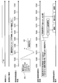
- the irradiation control device 120 acquires the current time from the timing control unit 122. In addition, when the exposure button is pressed, the irradiation control device 120 acquires the current time from the timing control unit 122. In FIG. 2, the irradiation control device 120 acquires the time value 10260 from the timing control unit 122.
- the irradiation control device 120 is notified of the irradiation time when radiation irradiation is started. Specifically, at the time when a predetermined time has elapsed from the current time, an exposure start advance notification time at which the exposure is started is set. The exposure start scheduled time is calculated by adding a preset time to the current time.
- the time to be added is a time with sufficient time between the time when the radiation imaging apparatus 101 and the irradiation control apparatus 120 transmit (message exchange) and the time when the radiation imaging apparatus 101 shifts to the imaging preparation operation for radiation detection. . Also, the time to be added can be set to a time that does not cause the operator to wait unnecessarily and to reduce the feeling of operation. Further, the time value to be added may be calculated and set in advance at the time of system design, or may be dynamically determined by prior negotiation by communication between the irradiation control apparatus 120 and the radiation imaging apparatus 101. .
- the time value 40 is added, and the scheduled exposure start time 10300 is calculated.
- the irradiation control device 120 transmits, to the radiation imaging apparatus 101, irradiation information on the irradiation time (scheduled start of irradiation) at which the irradiation of radiation is started.
- the irradiation control apparatus 120 transmits, to the radiation imaging apparatus 101, an imaging request message 200 for requesting start of imaging.
- the imaging request message 200 includes the above-mentioned scheduled start time of exposure as a parameter.
- the imaging request message 200 includes information corresponding to a radiation irradiation time length (a radiation pulse length, an irradiation window, etc.) and an irradiation cycle (frame rate etc.).
- a radiation irradiation time length a radiation pulse length, an irradiation window, etc.
- an irradiation cycle frame rate etc.
- the radiation time when radiation irradiation is started is transmitted to the radiation imaging apparatus 101 from the outside.
- the radiation imaging apparatus 101 that has received the imaging request message 200 acquires the current time from its own clock control unit 106.
- the radiation imaging apparatus 101 compares the current time with the scheduled exposure start time received in the message, and checks the imaging preparation operation (or radiation detection operation) at the scheduled exposure start time in light of the imaging mode to be imaged from now on. Determine if it can be completed.
- the radiation imaging apparatus 101 returns an imaging permission message 201 for permitting imaging (or radiation irradiation) to the irradiation control device 120 and plans the imaging preparation operation. Then, the drive control unit 105 executes a shooting preparation operation.
- the imaging control unit 102 receives the irradiation information on the irradiation time at which the irradiation of radiation starts, and the radiation imaging apparatus 101 transmits the radiation at the irradiation time based on the irradiation information (exposure start advance notice time).
- the receiver 107 is controlled to be in a detectable state.
- the radiation imaging apparatus 101 transmits, to the irradiation control apparatus 120, imaging permission information (imaging permission message 201) indicating that the image receiver 107 is in a state capable of detecting radiation at the irradiation time.
- the irradiation control device 120 controls the radiation generation device 110 to emit radiation when the imaging permission message 201 is received by a predetermined time before the irradiation time (before the irradiation start prediction time). For example, if the irradiation control apparatus 120 receives the imaging permission message 201 before the time indicated by the timing control unit 122 of its own reaches the irradiation start scheduled time, the irradiation control apparatus 120 starts generation of the timing pulse of radiation irradiation from the irradiation start scheduled time. Do.
- the irradiation control device 120 plans the irradiation operation of the radiation based on the time of the timing control unit 122 so that the predetermined radiation pulse length and frame rate can be obtained, and the irradiation pulse generation unit 123 Execute the irradiation operation.
- the irradiation control device 120 controls the radiation generator (irradiation means) 110 so as to irradiate radiation at the irradiation time.
- the radiation imaging apparatus 101 that has completed the imaging preparation operation prepares for radiation irradiation and places the operation of the image receiver 107 in the accumulation state when the time indicated by the timing control unit 106 of its own comes to the exposure start scheduled time. Then, after the time corresponding to the length of the radiation pulse has elapsed from the accumulation state (in FIG. 2, after the time indicated by the timing control unit 106 reaches 10310), the accumulated charge (information) is In the read-out state, radiation image data is acquired based on the read charge.
- the radiation imaging apparatus 101 plans an imaging operation (such as an accumulation operation or a readout operation) based on the time of the time control unit 106 so as to have a predetermined frame rate. Then, the imaging control unit 102 executes an imaging operation.
- an imaging operation such as an accumulation operation or a readout operation
- the radiation control apparatus 120 generates a timing pulse for radiation irradiation under the condition that the imaging permission message 201 is received.
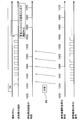
- the operation in the case where this condition can not be satisfied due to the message being lost or greatly delayed in the communication network is shown in FIG.
- the irradiation control device 120 does not generate a pulse even when the time indicated by the timing control unit 106 reaches the scheduled irradiation start time 10300.
- the radiation imaging apparatus 101 can not know whether the imaging permission message 201 transmitted by the radiation imaging apparatus 101 has reached the irradiation control apparatus 120, acquisition of radiation image data at the scheduled start of exposure 10300 is performed. Start. As a result, the radiation imaging apparatus 101 acquires a dark image which has not been irradiated, but this is an imaging operation in a state where the object is not irradiated with radiation, and therefore there is no harm of unnecessary exposure.
- the irradiation control device 120 controls the radiation generation device 110 not to irradiate radiation when the imaging permission information is not received by a predetermined time before the irradiation time (before the exposure start predicted time).
- the event that the photographing permission message 201 does not reach does not occur only by the disappearance of the photographing permission message 201 as described above.
- the radiation imaging apparatus 101 may not reply to the imaging permission message 201 in the first place because the imaging request message 200 has disappeared, or the imaging request message 200 may be delayed. Also, there may be a case where the radiation imaging apparatus 101 determines that imaging can not be performed and does not send a reply due to the reason of the radiation imaging apparatus 101 side.
- the radiation imaging apparatus 101 may return an imaging disable message (abnormal message) to the irradiation control apparatus 120 instead of the imaging permission message 201. In any case, it is possible to avoid giving unnecessary radiation to the subject.
- the radiation imaging apparatus 101 regularly transmits the normal message 202 to the irradiation control apparatus 120 while continuing the imaging operation after exchanging the message for starting imaging. While receiving the normal message 202, the irradiation control apparatus 120 determines that the radiation imaging apparatus 101 continues to operate normally.
- the radiation imaging apparatus 101 transmits, to the irradiation control device 120, normal information (normal message) indicating that the receiver 107 is operating normally. Then, the irradiation control device 120 determines the normality or abnormality of the image receiver 107 based on the normality information. The irradiation control device 120 controls the radiation imaging device 101 to emit radiation when the image receiver 107 is normal, and controls the radiation generation device 110 not to emit radiation when the image receiver 107 is abnormal. Do.
- the irradiation control apparatus 120 controls the radiation imaging apparatus 101 to emit radiation based on the normal information.
- the irradiation control apparatus 120 can also determine the abnormality of the radiation imaging apparatus 101 based on the frequency of omission of the normal message 202.
- the interval of transmission and reception of the normal message 202 may be set to a time interval shorter than a predetermined threshold so that prompt determination can be made. However, this threshold can be set to a time interval long enough not to load the communication network.
- the irradiation control apparatus 120 irradiates radiation based on at least one of presence / absence of reception of normal messages, frequency of reception, interval of reception, time of reception, and number of receptions. To control.
- FIG. 5 shows how the normal message 202 is dropped.
- the irradiation control device 120 stops generation of the timing pulse of radiation irradiation, and irradiation is not performed. Let's do it.
- the irradiation control apparatus 120 can not determine the state of the radiation imaging apparatus 101 or the communication network, such as whether the imaging operation of the radiation imaging apparatus 101 is abnormal or the normal message 202 is not achieved due to a malfunction of the communication network. Stop the exposure.
- the radiation may be stopped while the radiation imaging apparatus 101 continues the imaging operation.
- the radiation imaging apparatus 101 acquires a dark image which has not been irradiated.
- this is an imaging operation in a state where the object is not irradiated with radiation, there is no harm of unnecessary exposure.
- the above description is the stop of exposure due to the fact that the irradiation control apparatus 120 can not passively determine whether the operation of the radiation imaging apparatus 101 is normal based on the normal message 202. Besides, the imaging operation or the irradiation operation is also stopped by the radiation imaging apparatus 101 actively notifying the irradiation control apparatus 120 of its own abnormality.
- the radiation imaging apparatus 101 detects an abnormality in its own operation and determines that the image reception operation can not be maintained, it stops transmitting the normal message 202 and starts transmitting the abnormal message 204. At this time, similarly to the normal message 202, the abnormal message 204 is periodically repeated.
- the irradiation control device 120 immediately stops the generation of the timing pulse of the radiation irradiation without waiting for the determination of the missing frequency of the normal message 202. Then, the irradiation control device 120 sends a stop request message 205 back to the radiation imaging apparatus 101.
- the radiation imaging apparatus 101 can not detect radiation (including the case where radiation image data can not be output), the radiation imaging apparatus 101 is not operating normally. And transmit the abnormality information (abnormal message) to the irradiation control apparatus 120. Then, the irradiation control device 120 determines the normality or abnormality of the image receiver 107 based on the abnormality information. The radiation control device 120 controls the radiation generation device 110 to emit radiation when the image receiver 107 is normal, and controls the radiation generation device 110 not to emit radiation when the image receiver 107 is abnormal. Do.
- the irradiation control device 120 determines the abnormality of the image receiver 107 and controls the radiation generation device 110 so as not to irradiate the radiation.
- the radiation control apparatus 120 transmits stop request information (stop request message) for requesting the operation stop of the image receiver 107 to the radiation imaging apparatus 101 when the radiation generator 110 stops the irradiation of the radiation.
- the irradiation control device 120 sends back a stop request message 205 each time the abnormal message 204 arrives.
- the radiation imaging apparatus 101 receives the stop request message 205 from the irradiation control apparatus 120, it stops the repeated transmission of the abnormal message 204.
- the transmission interval of the abnormal message 204 does not have to be the same as the transmission interval of the normal message 202.
- the transmission interval of the abnormal message 204 can be as short as possible so that the abnormality can be promptly transmitted, and the transmission interval of the abnormal message 204 may be shorter than the transmission interval of the normal message 202.
- a stop signal is transmitted to the irradiation control device 120.
- the irradiation control device 120 immediately stops the generation of the timing pulse of radiation irradiation.
- the irradiation control device 120 transmits the stop request message 203 to the radiation imaging apparatus 101.
- the radiation imaging apparatus 101 having received the stop request message 203 stops the imaging operation.
- the radiation imaging apparatus 101 confirms the stop request message 203, and transmits a response message 206 to the irradiation control apparatus 120.
- the irradiation control apparatus 120 repeatedly transmits the stop request message 203 to the radiation imaging apparatus 101 until the response message 206 reaches the irradiation control apparatus 120. That is, when the radiation imaging apparatus 101 receives the stop request information, it transmits response information (a response message) indicating that the stop request information has been received to the irradiation control apparatus 120, and the irradiation control apparatus 120 receives the response information. If it does, the transmission of the stop request information is stopped. Thus, the normal stop is completed.
- the radiation may be stopped while the radiation imaging apparatus 101 continues the imaging operation. In this case, the radiation imaging apparatus 101 acquires a dark image which has not been irradiated. However, since this is an imaging operation in a state where the object is not irradiated with radiation, there is no harm of unnecessary exposure.
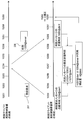
- FIG. 7 A procedure for establishing time synchronization by communication on a communication network is shown in FIG.
- the clock control unit 122 operates as a time server (ie, a clock serving as a reference), and the clock control unit 106 operates as a time client (ie, a clock corrected based on the time server).
- the radiation imaging apparatus 101 transmits a time request message 207 for requesting the irradiation control apparatus 120 to transmit the time (time information) of the timing control unit 122 to the irradiation control apparatus 120 through the wired communication unit 104 or the wireless communication unit 103.
- the transmission time of the time request message 207 in the radiation imaging apparatus 101 (the time of the clock control unit 106) is included in the time request message 207.
- the time value 10254 is recorded in the time request message 207.
- the irradiation control apparatus 120 that has received the time request message 207 sends the time message 208 back to the radiation imaging apparatus 101.
- the transmission time of the time message 208 in the irradiation control apparatus 120 (the time of the time control unit 122) is included in the time message 208.
- time value 10254 is included in time message 208.
- the radiation imaging apparatus 101 acquires the reception time of the time message 208 at the time of the timing control unit 106.
- the time value 10260 is acquired.
- the radiation imaging apparatus 101 corrects the time information (time of the time control unit 106) to which the radiation imaging apparatus 101 refers based on the time information (time of the time control unit 122) to which the irradiation control apparatus 120 refers. Do. In this embodiment, the radiation imaging apparatus 101 is based on the time information referred to by the irradiation control apparatus 120, the transmission time of the time request information, and the reception time of the time information from the irradiation control apparatus 120 by the response of the time request information. The time information referred to by the radiation imaging apparatus 101 is corrected.
- the radiation control device 120 may store the time difference, and may control the radiation source 109 and the radiation imaging apparatus 101 based on the time when the clock of the time control unit 122 is adjusted by the stored time difference.
- the radiation imaging apparatus 101 may store the time difference, and the radiation imaging apparatus 101 may operate by adding the time difference to the time of the timing control unit 106 with respect to the operation timing from the irradiation control apparatus 120.
- the correction amount is determined based on transmission and reception of one time request message 207 and time message 208, since the propagation time of the message may actually vary, the correction amount should be adjusted. May be required. Therefore, the correction amount may be calculated statistically by executing transmission and reception of the time request message 207 and the time message 208 a plurality of times.
- a predetermined number of correction amounts are collected in ascending order of round trip time to calculate an average of correction amounts.
- the correction amount may be calculated.
- the round trip time in the present embodiment is the time from when the radiation imaging apparatus 101 transmits the time request message 207 to when the time message 208 is received.
- the correction amount may be calculated from a time difference within an allowable error range based on the irradiation period of radiation with respect to the period of the accumulation state.
- the correction amount is added at one time in the above case, if the correction is made at once, the evenness of the drive control of the image receiver 107 is greatly lost immediately after the correction, and the image quality is noticeable by one frame. Cause a phenomenon that differs from Therefore, the correction amount larger than the predetermined threshold may be divided into multiple times over time, and may be added to or subtracted from the timing control unit 106.
- the transmission time from the radiation imaging apparatus 101 in FIG. 7 may be included in the time request message 207, and the transmission time of the time request message 207 and the transmission time of the time message 208 may be included in the time message 208. This enables processing even if the message disappears and the corresponding time request message 207 and time message 208 pair becomes unclear.
- the procedure of FIG. 7 is shown to show the minimum operation principle, but the synchronous processing of time is not limited to this, and in the case where the complexity in implementation is acceptable. , You may use the existing complicated time synchronization protocol.
- Known protocols include RFC 4330 SNTP and IEEE 1588 PTP.
- the system of the present embodiment combines the communication procedure of the imaging process for controlling the start and stop of imaging and the communication procedure of the synchronization process for synchronizing the times of the plurality of time control units. Operated. These communication procedures are not exclusive and do not necessarily have to be coordinated.
- the communication procedure of the time synchronization process may be performed while the photographing is performed and the normal message 202 is periodically transmitted.
- the time difference between the clock control units 106 and 122 once synchronized becomes large again if the photographing time becomes long, even if the communication procedure of the time synchronization processing is periodically executed during the photographing.
- the interval between the normal messages 202 and the interval between the time request messages 207 need not necessarily be correlated, and operations can be performed at different intervals. However, the intervals of a plurality of messages may be correlated, for the purpose of, for example, improving synchronization accuracy by avoiding temporal duplication of message transmission and reception.
- the correction amount is calculated statistically as a result of the communication procedure of time synchronization processing, but the result of the statistical processing may affect the control of start and stop of imaging. If the variance of the plurality of correction amounts obtained by the plurality of time request messages 207 is larger than the predetermined threshold, it is difficult to obtain the truly necessary correction amount, and it is expected that time synchronization can be established before correction. Too low. For this reason, when the accuracy of the correction amount is low, it may be considered that time synchronization can not be established, and control may be made to discontinue the start of imaging or to interrupt imaging.
- the irradiation control apparatus 120 or the radiation imaging apparatus 101 stops the operation relating to irradiation or detection of radiation when a statistical value (such as variance or standard deviation) regarding the variation of the correction amount of time information exceeds a predetermined threshold. .
- the radiation imaging apparatus 101 is controlled not to send back the imaging permission message 201 to the imaging request message 200.
- the radiation imaging apparatus 101 may be controlled to interrupt transmission of the normal message 202 during imaging and start transmission of the abnormal message 204.
- the accuracy of synchronization which is the basis for such non-permission or interruption of imaging, can be variable according to the parameters for imaging a moving image.
- the predetermined threshold value of the statistical value (such as variance or standard deviation) regarding the variation of the correction amount of the time information is variable according to the radiation irradiation condition or the radiation detection condition.
- the radiation detection period can be extended, so that imaging can be performed even if the synchronization of time is low.
- the timing control unit 122 included in the irradiation control device 120 is the reference timing unit (master clock) for operating the system.
- the timing control unit 106 of the radiation imaging apparatus 101 may be a reference timing unit (master clock) for operating the system.
- the irradiation control apparatus 120 corrects the time information (time of the time control unit 122) to which the irradiation control apparatus 120 refers based on the time information (time of the time control unit 106) to which the radiation imaging apparatus 101 refers. .
- the irradiation control apparatus 120 performs irradiation control based on time information referred to by the radiation imaging apparatus 101, transmission time of time request information, and reception time of time information.
- the time information referred to by the apparatus 120 is corrected.
- the time request information is a time request message for requesting the radiation imaging apparatus 101 to transmit the time (time information) of the time control unit 106.
- the time information is a time message from the radiation imaging apparatus 101 in response to the time request message.
- the irradiation control device 120 may correct the time information to be referred to based on the synchronization pulse of the radiation generation device 110.
- FIG. 8 shows a time synchronization operation in a system in which the radiation generator 110 generates a pulse according to the imaging frame rate, and the timing control unit 122 follows this.
- the irradiation control device 120 may correct the time information (time of the time control unit 122) to which the irradiation control device 120 refers based on the time information (synchronization pulse) to which the radiation generation device 110 refers. .
- the radiation generator 110 constantly generates synchronization pulses according to the imaging frame rate and transmits the synchronization pulses to the irradiation controller 120. Even if the radiation generator 110 is generating the synchronous pulse, the radiation generator 110 does not perform the radiation unless the radiation control device 120 permits the radiation.
- the synchronization pulse generated by the radiation generator 110 is generated according to the source oscillator of the radiation generator 110, and the synchronization pulse can not completely eliminate the error of the time advance of the time control unit 122 of the irradiation control device 120. If not synchronized, the time difference between the synchronization pulse of the radiation generation device 110 and the time of the irradiation control device 120 is enlarged, and the synchronization pulse is not generated at the pulse generation time calculated based on the time of the time control unit 122. Fall down.
- the irradiation control device 120 compares the generation time of the given synchronization pulse with the time of the clock control unit 122, and corrects the clock control unit 122 to detect synchronization when the difference between the two is detected. Make the pulse follow.
- the radiation generator 110 and the irradiation controller 120 are directly electrically connected without the communication network. Therefore, since the variation of the estimated value of the correction amount due to the communication network is small, the time difference may be corrected immediately after the difference is detected without performing statistical processing for calculating the true correction value. Therefore, the timing control unit 122 can accurately follow the synchronization pulse.
- Time synchronization between the time control unit 122 and the time control unit 106 operates in the same manner as in the first embodiment.
- the timing control unit 122 follows the synchronization pulse
- the timing control unit 106 follows this with a slight delay. Therefore, the difference between the synchronization pulse and the time of the time control unit 106 is considered to be larger than that of the first embodiment, but as described above, the follow operation of the time control unit 122 for the synchronization pulse is precise. It does not have a big influence on the whole.
- FIG. 9 shows an operation at the start of shooting in the present embodiment.
- the irradiation control device 120 detects that the exposure button is pressed, it predicts the generation time of the synchronous pulse 400, 401, 402 after the pressing of the irradiation button based on the time of the timing control unit 122.
- the irradiation control device 120 takes synchronization pulse times corresponding to the exposure start forecasting time that can be predicted to be in time from the synchronization pulses 400, 401, and 402, which can predict that the imaging operation will be in time in consideration of time such as imaging preparation operation of the radiation imaging device 101. decide.
- the synchronization pulse 401 is adopted as the scheduled start time of exposure.
- the subsequent message exchange procedure is the same as that of the first embodiment, and thus the description thereof is omitted.
- the irradiation control device 120 that has received the imaging permission message 201 notifies the radiation generation device 110 that the imaging is permitted.
- the radiation generator 110 receives this notification and generates radiation in accordance with the synchronization pulse generated by itself.
- the present invention also includes the case where clocking means other than the clock control units 106 and 122 exist on the communication network and are used as a master clock.
- the radiation imaging apparatus 101 corrects time information (time of the timing control unit 106) to which the radiation imaging apparatus 101 refers based on a master clock (reference time information) serving as a reference.
- the irradiation control device 120 corrects time information (time of the time control unit 122) to which the irradiation control device 120 refers based on a master clock (reference time information) as a reference.
- a time server serving as a master clock exists on the communication network.
- the time server executes the same process as the process performed by the timing control unit 122 according to the first embodiment in FIG. 7.
- the timing control unit 122 operates as a time point client.
- the time control unit 106 and the time control unit 122 both communicate with the time server shown in FIG. 10, and correct their own time so as to follow this.
- the time client is the clock control unit 106, it is the clock control unit 106 that performs statistical estimation of the correction amount, but in the present embodiment, the clock control unit 122 also performs time correction. Since the client is a client, the same operation as the clock control unit 106 is performed. For this reason, when the timing control unit 122 of the irradiation control device 120 performs synchronization processing with the master clock, the accuracy of the synchronization becomes low, and the possibility of synchronization failure of the timing control unit 122 occurs.
- the radiation imaging apparatus 101 performs control so as not to give imaging permission when the accuracy of the correction amount is low, but in the present embodiment, the irradiation control is performed when the accuracy of the correction amount is low. Control may be performed so that the device 120 does not give radiation permission.
- the irradiation control device 120 ignores this and performs an operation such as not transmitting the imaging request message 200 to the radiation imaging apparatus 101.
- the communication procedure for synchronizing the time assumes that the time request message and the time reply message are transmitted at almost the same propagation time.
- the propagation times of transmitted and received messages may not be equal.
- the asymmetry of the propagation time strongly appears in the communication between the wireless LAN access point (AP) and each wireless station.
- FIG. 11 shows how a communication procedure for synchronizing time in such a communication network is performed.
- the time of the time control unit 122 after execution of the synchronization process is 10259
- the time of the time control unit 106 is 10257
- asymmetry of the propagation time causes a deviation even after correction. I understand that I am doing it. If the asymmetry is not temporary but stable, repeating synchronization processing does not eliminate the time difference caused by the asymmetry.
- the wire communication unit 104 and the wireless communication unit 103 are simultaneously connected to the communication network when the radiation imaging system 100 is activated, and the time synchronization procedure is performed on the clock control unit 106 by both communication means. be able to.
- time synchronization is temporarily performed using the wired communication unit 104 and the wireless communication unit 103, the time synchronized by the wired communication unit 104 is made true, and the time synchronized by the wireless communication unit 103 includes a steady correction deviation.
- the difference between the two times is the correction deviation of the synchronization processing in the wireless communication unit.
- the radiation imaging apparatus 101 can communicate with the irradiation control apparatus 120 by the first communication unit (wire communication) and the second communication unit (wireless communication) that propagate time information.
- the radiation imaging apparatus 101 then refers to the time information (time control unit) to which the radiation imaging apparatus 101 refers based on time information (time of the time control unit 122) received from the irradiation control apparatus 120 via the first communication unit. First correction processing for correcting the time 106) is performed.
- the radiation imaging apparatus 101 also refers to the time information (time control unit) to which the radiation imaging apparatus 101 refers based on time information (time of the time control unit 122) received from the irradiation control apparatus 120 via the second communication unit.
- a second correction process is performed to correct the time 106).
- the radiation imaging apparatus 101 corrects the correction amount by the second correction processing based on the correction amount by the first correction processing. In this case, since the error of the time information by the first correction process is smaller than the error of the time information by the second correction process, the correction amount by the second correction process is determined with the time by the first correction process as the true time. Is corrected.
- the true synchronization time by the wired communication unit 104 is used as the true synchronization time in the present embodiment, the present invention is not limited to this.
- the true synchronization time may be calculated using a direct synchronization means not via the communication network. It may be set.
- the communication procedure of the synchronization process may be continued even during imaging.
- the communication procedure of synchronous processing Can be configured so that the time difference does not increase rapidly.
- the means for time synchronization is not limited to the communication procedure described in the first embodiment, and may be a synchronization means not via a communication network.
- the direct electrical connection is disconnected and the imaging operation is performed, and the imaging operation is performed according to the elapsed time since the disconnection. Is automatically interrupted, requiring the operator to resynchronize.
- the radiation generation apparatus and the radiation imaging apparatus can be imaged in synchronization, and unnecessary radiation exposure can be performed by stopping radiation irradiation when a situation in which synchronization can not be performed is estimated. It can be avoided. Further, by performing time synchronization processing, it is possible to improve the accuracy of shooting synchronization.
- the radiation control apparatus 120 and the radiation imaging apparatus 101 each have an internal clock (time control units 122 and 106), and the radiation imaging apparatus 101 executes an imaging operation based on the time of its own internal clock. Then, the irradiation control device 120 controls pulsed radiation irradiation based on the time of its own internal clock and the time difference between the irradiation control device 120 and the radiation imaging apparatus 101.
- the radiation imaging system 100 includes at least an irradiation control device 120 that controls the timing of pulsed radiation irradiation, and one or more radiation imaging devices 101, and is mutually connected by a communication network line.
- the irradiation control apparatus 120 notifies each of the radiation imaging apparatuses 101 in the system of a message including the time of pulse irradiation of the radiation via the communication network line.
- Each radiation imaging apparatus 101 that has received the notification returns a confirmation response to the irradiation control apparatus 120.
- the irradiation control apparatus 120 continues pulse-shaped radiation irradiation at a specific frame interval, and the response is received within a predetermined number of timing pulses. If not, stop the irradiation.
- the irradiation control apparatus 120 or the radiation imaging apparatus 101 calculates temporal change of the correction amount based on the correction amount of the time information, and estimates the correction amount based on the temporal change. Then, when the estimated correction amount exceeds the predetermined threshold, the irradiation control device 120 executes at least one of correction of time information referred to by the irradiation control device 120 and stop of the operation related to irradiation of radiation. If the estimated correction amount exceeds the predetermined threshold, the radiation imaging apparatus 101 executes at least one of correction of time information to which the radiation imaging apparatus 101 refers and stop of operation relating to detection of radiation.
- the time information is corrected a plurality of times, the change amount per time of each correction amount is calculated, and the elapsed time is integrated to the average of each change amount. Is estimated.
- the present invention supplies a program that implements one or more functions of the above-described embodiments to a system or apparatus via a network or storage medium, and one or more processors in a computer of the system or apparatus read and execute the program. Can also be realized. It can also be implemented by a circuit (eg, an ASIC) that implements one or more functions.
- a circuit eg, an ASIC
- Reference Signs List 100 radiation imaging system 101 radiation imaging apparatus (detection control unit) 102 imaging control unit 103 wireless communication unit 104 wired communication unit 105 drive control unit 106, 122 clock control unit 107 receiver (detection unit) 109 radiation source 110 radiation generator (irradiation means) 115 radiation button 120 irradiation control device (irradiation control means) 121 wired communication unit 123 irradiation pulse generator
Landscapes
- Health & Medical Sciences (AREA)
- Life Sciences & Earth Sciences (AREA)
- Engineering & Computer Science (AREA)
- Medical Informatics (AREA)
- Physics & Mathematics (AREA)
- General Health & Medical Sciences (AREA)
- Pathology (AREA)
- Molecular Biology (AREA)
- High Energy & Nuclear Physics (AREA)
- Surgery (AREA)
- Animal Behavior & Ethology (AREA)
- Veterinary Medicine (AREA)
- Biophysics (AREA)
- Public Health (AREA)
- Heart & Thoracic Surgery (AREA)
- Nuclear Medicine, Radiotherapy & Molecular Imaging (AREA)
- Optics & Photonics (AREA)
- Radiology & Medical Imaging (AREA)
- Biomedical Technology (AREA)
- General Physics & Mathematics (AREA)
- Biochemistry (AREA)
- Analytical Chemistry (AREA)
- Chemical & Material Sciences (AREA)
- Immunology (AREA)
- Toxicology (AREA)
- Spectroscopy & Molecular Physics (AREA)
- Computer Networks & Wireless Communication (AREA)
- Apparatus For Radiation Diagnosis (AREA)
- Measurement Of Radiation (AREA)
Priority Applications (5)
| Application Number | Priority Date | Filing Date | Title |
|---|---|---|---|
| EP18781430.6A EP3607883B1 (en) | 2017-04-06 | 2018-03-29 | Radiographic image capturing system, radiographic image capturing device, radiographic image capturing method, and program |
| EP24181890.5A EP4422355A3 (en) | 2017-04-06 | 2018-03-29 | Radiation imaging apparatus |
| CN201880022451.1A CN110520050B (zh) | 2017-04-06 | 2018-03-29 | 放射线成像系统、放射线成像装置、放射线成像方法和计算机可读介质 |
| EP22195878.8A EP4137056B1 (en) | 2017-04-06 | 2018-03-29 | Radiation imaging apparatus |
| US16/593,032 US11438995B2 (en) | 2017-04-06 | 2019-10-04 | Radiation imaging system, radiation imaging apparatus, radiation imaging method, and computer-readable medium |
Applications Claiming Priority (2)
| Application Number | Priority Date | Filing Date | Title |
|---|---|---|---|
| JP2017076303A JP6971611B2 (ja) | 2017-04-06 | 2017-04-06 | 放射線撮影システム、放射線撮影装置、放射線撮影方法、及びプログラム |
| JP2017-076303 | 2017-04-06 |
Related Child Applications (1)
| Application Number | Title | Priority Date | Filing Date |
|---|---|---|---|
| US16/593,032 Continuation US11438995B2 (en) | 2017-04-06 | 2019-10-04 | Radiation imaging system, radiation imaging apparatus, radiation imaging method, and computer-readable medium |
Publications (1)
| Publication Number | Publication Date |
|---|---|
| WO2018186275A1 true WO2018186275A1 (ja) | 2018-10-11 |
Family
ID=63712960
Family Applications (1)
| Application Number | Title | Priority Date | Filing Date |
|---|---|---|---|
| PCT/JP2018/013101 Ceased WO2018186275A1 (ja) | 2017-04-06 | 2018-03-29 | 放射線撮影システム、放射線撮影装置、放射線撮影方法、及びプログラム |
Country Status (5)
| Country | Link |
|---|---|
| US (1) | US11438995B2 (https=) |
| EP (3) | EP3607883B1 (https=) |
| JP (1) | JP6971611B2 (https=) |
| CN (1) | CN110520050B (https=) |
| WO (1) | WO2018186275A1 (https=) |
Cited By (3)
| Publication number | Priority date | Publication date | Assignee | Title |
|---|---|---|---|---|
| EP3675393A1 (en) * | 2018-12-27 | 2020-07-01 | Canon Kabushiki Kaisha | Time synchronization system, method of controlling time synchronization system, and radiation imaging system |
| JP2021045359A (ja) * | 2019-09-19 | 2021-03-25 | コニカミノルタ株式会社 | 放射線撮影システム、撮影制御装置、放射線撮影方法及び放射線撮影プログラム |
| TWI748389B (zh) * | 2020-03-25 | 2021-12-01 | 佛教慈濟醫療財團法人 | 放射檢查智慧提醒裝置及方法 |
Families Citing this family (8)
| Publication number | Priority date | Publication date | Assignee | Title |
|---|---|---|---|---|
| JP6971611B2 (ja) | 2017-04-06 | 2021-11-24 | キヤノン株式会社 | 放射線撮影システム、放射線撮影装置、放射線撮影方法、及びプログラム |
| JP6811673B2 (ja) * | 2017-04-25 | 2021-01-13 | 富士フイルム株式会社 | 放射線照射検出システムおよび放射線発生装置 |
| JP7101494B2 (ja) * | 2018-02-14 | 2022-07-15 | キヤノン株式会社 | 放射線撮影装置及び放射線撮影システム、ならびにそれらの制御方法 |
| JP7292952B2 (ja) | 2019-04-25 | 2023-06-19 | キヤノン株式会社 | 放射線撮影システム、照射制御装置及び放射線撮影システムの制御方法 |
| JP2020199139A (ja) * | 2019-06-12 | 2020-12-17 | コニカミノルタ株式会社 | 制御装置、放射線撮影システム、制御方法及びプログラム |
| JP7530216B2 (ja) * | 2020-06-05 | 2024-08-07 | キヤノン株式会社 | 放射線撮像システム、および、放射線撮像装置 |
| JP7211407B2 (ja) * | 2020-12-24 | 2023-01-24 | コニカミノルタ株式会社 | 回診車 |
| CN119014889A (zh) * | 2023-05-23 | 2024-11-26 | 佳能株式会社 | 放射线检测系统、控制设备和信息处理装置 |
Citations (7)
| Publication number | Priority date | Publication date | Assignee | Title |
|---|---|---|---|---|
| JPS544587B2 (https=) | 1972-01-12 | 1979-03-08 | ||
| JP2004024682A (ja) * | 2002-06-27 | 2004-01-29 | Canon Inc | 放射線検出装置及び放射線検出システム |
| JP2008145101A (ja) * | 2005-03-25 | 2008-06-26 | Konica Minolta Medical & Graphic Inc | カセッテ型放射線画像検出器及び放射線画像検出システム |
| JP2011019800A (ja) * | 2009-07-17 | 2011-02-03 | Ge Medical Systems Global Technology Co Llc | X線診断装置およびx線ct装置 |
| JP2013138360A (ja) * | 2011-12-28 | 2013-07-11 | Canon Inc | 撮影制御装置、放射線撮影システム及び撮影制御方法 |
| WO2014108929A1 (ja) * | 2013-01-08 | 2014-07-17 | 株式会社島津製作所 | 放射線撮影装置 |
| JP2017076303A (ja) | 2015-10-16 | 2017-04-20 | 株式会社フィールトラスト | 情報処理システム |
Family Cites Families (6)
| Publication number | Priority date | Publication date | Assignee | Title |
|---|---|---|---|---|
| JP5404587B2 (ja) | 2010-12-03 | 2014-02-05 | キヤノン株式会社 | 撮影装置、放射線撮影システム及び制御方法 |
| US20130279661A1 (en) * | 2012-04-19 | 2013-10-24 | Canon Kabushiki Kaisha | Radiant ray generation control apparatus, radiation imaging system, and method for controlling the same |
| JP2014045938A (ja) * | 2012-08-31 | 2014-03-17 | Fujifilm Corp | 放射線撮影システムおよびその通信方法、並びに放射線画像検出装置 |
| JP6486090B2 (ja) * | 2014-12-09 | 2019-03-20 | キヤノン株式会社 | 放射線撮像システム及びその制御方法 |
| JP6971611B2 (ja) | 2017-04-06 | 2021-11-24 | キヤノン株式会社 | 放射線撮影システム、放射線撮影装置、放射線撮影方法、及びプログラム |
| JP7089372B2 (ja) | 2018-02-15 | 2022-06-22 | キヤノン株式会社 | 放射線撮影装置、放射線撮影装置の制御方法、放射線撮影システム、およびプログラム |
-
2017
- 2017-04-06 JP JP2017076303A patent/JP6971611B2/ja active Active
-
2018
- 2018-03-29 EP EP18781430.6A patent/EP3607883B1/en active Active
- 2018-03-29 WO PCT/JP2018/013101 patent/WO2018186275A1/ja not_active Ceased
- 2018-03-29 CN CN201880022451.1A patent/CN110520050B/zh active Active
- 2018-03-29 EP EP22195878.8A patent/EP4137056B1/en active Active
- 2018-03-29 EP EP24181890.5A patent/EP4422355A3/en not_active Withdrawn
-
2019
- 2019-10-04 US US16/593,032 patent/US11438995B2/en active Active
Patent Citations (7)
| Publication number | Priority date | Publication date | Assignee | Title |
|---|---|---|---|---|
| JPS544587B2 (https=) | 1972-01-12 | 1979-03-08 | ||
| JP2004024682A (ja) * | 2002-06-27 | 2004-01-29 | Canon Inc | 放射線検出装置及び放射線検出システム |
| JP2008145101A (ja) * | 2005-03-25 | 2008-06-26 | Konica Minolta Medical & Graphic Inc | カセッテ型放射線画像検出器及び放射線画像検出システム |
| JP2011019800A (ja) * | 2009-07-17 | 2011-02-03 | Ge Medical Systems Global Technology Co Llc | X線診断装置およびx線ct装置 |
| JP2013138360A (ja) * | 2011-12-28 | 2013-07-11 | Canon Inc | 撮影制御装置、放射線撮影システム及び撮影制御方法 |
| WO2014108929A1 (ja) * | 2013-01-08 | 2014-07-17 | 株式会社島津製作所 | 放射線撮影装置 |
| JP2017076303A (ja) | 2015-10-16 | 2017-04-20 | 株式会社フィールトラスト | 情報処理システム |
Non-Patent Citations (1)
| Title |
|---|
| See also references of EP3607883A4 |
Cited By (5)
| Publication number | Priority date | Publication date | Assignee | Title |
|---|---|---|---|---|
| EP3675393A1 (en) * | 2018-12-27 | 2020-07-01 | Canon Kabushiki Kaisha | Time synchronization system, method of controlling time synchronization system, and radiation imaging system |
| US11442182B2 (en) | 2018-12-27 | 2022-09-13 | Canon Kabushiki Kaisha | Time synchronization system, method of controlling time synchronization system, and radiation imaging system |
| JP2021045359A (ja) * | 2019-09-19 | 2021-03-25 | コニカミノルタ株式会社 | 放射線撮影システム、撮影制御装置、放射線撮影方法及び放射線撮影プログラム |
| US11311265B2 (en) | 2019-09-19 | 2022-04-26 | Konica Minolta, Inc. | Radiographic imaging system, imaging control apparatus and radiographic imaging method |
| TWI748389B (zh) * | 2020-03-25 | 2021-12-01 | 佛教慈濟醫療財團法人 | 放射檢查智慧提醒裝置及方法 |
Also Published As
| Publication number | Publication date |
|---|---|
| US20200037426A1 (en) | 2020-01-30 |
| EP4422355A2 (en) | 2024-08-28 |
| EP3607883B1 (en) | 2022-11-02 |
| EP4137056B1 (en) | 2024-07-24 |
| CN110520050B (zh) | 2024-03-12 |
| EP4137056A1 (en) | 2023-02-22 |
| EP3607883A4 (en) | 2020-11-25 |
| US11438995B2 (en) | 2022-09-06 |
| EP3607883A1 (en) | 2020-02-12 |
| JP6971611B2 (ja) | 2021-11-24 |
| CN110520050A (zh) | 2019-11-29 |
| EP4422355A3 (en) | 2024-10-23 |
| JP2018175125A (ja) | 2018-11-15 |
Similar Documents
| Publication | Publication Date | Title |
|---|---|---|
| WO2018186275A1 (ja) | 放射線撮影システム、放射線撮影装置、放射線撮影方法、及びプログラム | |
| JP7764910B2 (ja) | 制御システム及び放射線画像撮影制御方法 | |
| JP5882670B2 (ja) | 放射線撮影装置、放射線撮影システム及びその処理方法 | |
| US11895428B2 (en) | Control apparatus, radiographic imaging system, control method, and recording medium | |
| JP6907982B2 (ja) | 放射線撮影システム | |
| US10736597B2 (en) | Radiographic apparatus, radiographic system, control methods thereof, and computer-readable storage medium | |
| EP3733070B1 (en) | Radiation imaging system, radiation control apparatus and method of controlling radiation imaging system | |
| US10856834B2 (en) | Radiation imaging apparatus, method of controlling radiation imaging apparatus, radiation imaging system, and non-transitory computer-readable storage medium | |
| CN111374684B (zh) | 时间同步系统及其控制方法以及放射线摄像系统 | |
| JP7050518B2 (ja) | 放射線撮影装置、放射線撮影システム、及び放射線撮影システムの制御方法 | |
| JP2025069782A (ja) | 放射線撮影システム | |
| JP2019141114A (ja) | 放射線撮影装置、放射線撮影システム、及び放射線撮影システムの制御方法 | |
| JP2022097704A (ja) | 放射線撮影システム | |
| JP2022100540A (ja) | 放射線撮影装置、放射線照射装置、放射線撮影システム及び回診車 | |
| JP5925245B2 (ja) | 装置、x線撮影システム、制御方法及びプログラム | |
| JP2019076219A (ja) | 放射線撮影システム、時刻同期方法、及びプログラム |
Legal Events
| Date | Code | Title | Description |
|---|---|---|---|
| 121 | Ep: the epo has been informed by wipo that ep was designated in this application |
Ref document number: 18781430 Country of ref document: EP Kind code of ref document: A1 |
|
| NENP | Non-entry into the national phase |
Ref country code: DE |
|
| ENP | Entry into the national phase |
Ref document number: 2018781430 Country of ref document: EP Effective date: 20191106 |