WO2018180875A1 - 円偏波アンテナ - Google Patents
円偏波アンテナ Download PDFInfo
- Publication number
- WO2018180875A1 WO2018180875A1 PCT/JP2018/011372 JP2018011372W WO2018180875A1 WO 2018180875 A1 WO2018180875 A1 WO 2018180875A1 JP 2018011372 W JP2018011372 W JP 2018011372W WO 2018180875 A1 WO2018180875 A1 WO 2018180875A1
- Authority
- WO
- WIPO (PCT)
- Prior art keywords
- antenna
- circularly polarized
- linear
- inverted
- open end
- Prior art date
Links
Images


Classifications
-
- H—ELECTRICITY
- H01—ELECTRIC ELEMENTS
- H01Q—ANTENNAS, i.e. RADIO AERIALS
- H01Q1/00—Details of, or arrangements associated with, antennas
- H01Q1/36—Structural form of radiating elements, e.g. cone, spiral, umbrella; Particular materials used therewith
- H01Q1/38—Structural form of radiating elements, e.g. cone, spiral, umbrella; Particular materials used therewith formed by a conductive layer on an insulating support
-
- H—ELECTRICITY
- H01—ELECTRIC ELEMENTS
- H01Q—ANTENNAS, i.e. RADIO AERIALS
- H01Q21/00—Antenna arrays or systems
- H01Q21/24—Combinations of antenna units polarised in different directions for transmitting or receiving circularly and elliptically polarised waves or waves linearly polarised in any direction
-
- H—ELECTRICITY
- H01—ELECTRIC ELEMENTS
- H01Q—ANTENNAS, i.e. RADIO AERIALS
- H01Q9/00—Electrically-short antennas having dimensions not more than twice the operating wavelength and consisting of conductive active radiating elements
- H01Q9/04—Resonant antennas
-
- H—ELECTRICITY
- H01—ELECTRIC ELEMENTS
- H01Q—ANTENNAS, i.e. RADIO AERIALS
- H01Q9/00—Electrically-short antennas having dimensions not more than twice the operating wavelength and consisting of conductive active radiating elements
- H01Q9/04—Resonant antennas
- H01Q9/30—Resonant antennas with feed to end of elongated active element, e.g. unipole
- H01Q9/42—Resonant antennas with feed to end of elongated active element, e.g. unipole with folded element, the folded parts being spaced apart a small fraction of the operating wavelength
Definitions
- the present invention relates to a circularly polarized antenna, and more particularly to a circularly polarized antenna using two antennas.
- a circular polarization antenna is used for the communication.
- a conventional circularly polarized antenna there is a microstrip antenna using a degenerate separation method.
- This circularly polarized antenna is an antenna having a shape obtained by cutting off two corners of a square microstrip antenna, and is shown in FIG.
- a circularly polarized wave antenna using a two-point feeding method there is an antenna that is circularly polarized by separately feeding power to two orthogonal sides of a square microstrip antenna. In this method, a rectangular or circular microstrip antenna is fed so that the phase difference is ⁇ / 2 at two feeding points that are spatially orthogonal to each other.
- the size of one side of the antenna is ⁇ g / 2 and a dielectric substrate larger than the antenna is required, resulting in a large size as a whole.
- ⁇ g is a wavelength within the dielectric substrate.
- the circularly polarized antenna of the two-point feeding method requires an external circuit such as a two distribution circuit for feeding power at two points, and there is a problem that the feeding system becomes complicated.
- An object of the present invention is to provide a circularly polarized antenna that can be more easily manufactured and reduced in size.
- the first linear antenna having at least one open end, and at least one open end, the open end side and the open end side of the first linear antenna. Are arranged at a predetermined interval and substantially orthogonal to the first linear antenna, and a second line having a phase difference of substantially ⁇ / 2 with respect to the first linear antenna at a frequency realizing circular polarization.
- the first linear antenna is arranged to be opposed to each other with a predetermined interval between the linear antenna, the open end side of the first linear antenna, and the open end side of the second linear antenna.
- an EM feeder that is electromagnetically connected to the second linear antenna; and the first linear antenna and the second linear antenna that are electrically connected to the EM feeder and are connected to the EM feeder.
- the first linear antenna is disposed substantially parallel to an end surface of the ground conductor plate, and an open end side faces the EM power feeding portion.
- the first linear antenna is disposed substantially parallel to an end surface of the ground conductor plate, and an open end side faces the EM power feeding portion. It is an inverted L antenna having an antenna main portion to be disposed, and a first short-circuit portion that short-circuits the opposite end portion of the antenna main portion on the open end side and the ground conductor plate.
- a circularly polarized antenna according to claim 1 is provided.
- the first linear antenna is a dipole antenna, and the circle according to any one of claims 1 to 3 A polarization antenna is provided.
- the second linear antenna is a dipole antenna, an inverted F antenna, or an inverted L antenna.
- a circularly polarized antenna according to any one of the claims is provided.
- the invention according to claim 7 provides the circularly polarized antenna according to claim 6, wherein the difference ⁇ is 0.1 f.
- a circularly polarized antenna according to any one of claims 1 to 8 is provided.
- each of the first linear antenna, the second linear antenna, and the EM feeder is formed of a plurality of layers connected to each other via.
- a circularly polarized antenna according to any one of claims 1 to 9 is provided.
- the shape of the antenna element portion is a linear shape, a meander shape, a helical shape, or a bent end shape, The circularly polarized antenna according to any one of claims 1 to 10 is provided.
- the present invention by one-point feeding by each of the open end portion of the first linear antenna and the open end portion of the second linear antenna, and the EM feeding portion disposed to be opposed to each other at a predetermined interval, It can be easily manufactured. Further, the size can be reduced by using the first and second linear antennas.
- the circularly polarized antenna according to the present embodiment uses a first linear antenna and a second linear antenna that are either a dipole antenna, an inverted F antenna, or an inverted L antenna.
- the open end side of the linear antenna is orthogonally arranged with a predetermined distance.
- the first linear antenna and the second linear antenna are adjusted so that the phase difference is substantially ⁇ / 2 at the frequency at which circular polarization is achieved.
- an EM power feeding part is disposed opposite to each of the open ends of the first linear antenna and the second linear antenna at a predetermined interval, and the power feeding line is electrically connected to the EM power feeding part.
- the circularly polarized antenna of the present embodiment it is possible to easily manufacture and reduce the size by realizing electromagnetic one-point feeding from both open ends of two orthogonal linear antennas.
- a circularly polarized antenna is obtained.
- the orthogonal arrangement of the antennas is arranged in an orthogonal state, and the arrangement in the orthogonal state is not limited to a right angle in a strict sense, and an axial ratio of 3 dB or less which is a good guideline for practical use as an antenna. It shall include the width of the angle that can be realized.
- an inverted F antenna 20 (first linear antenna) having an open end on one side of two orthogonal sides of the rectangular ground conductor plate 10 and a dipole antenna on the other side. 30 (second linear antenna) is disposed, and the EM power feeding portion 41 of the power feeding portion 40 is disposed opposite to both open ends.
- the opposite side of the open end side of the inverted F antenna 20 is short-circuited to the ground conductor plate 10 by the first short-circuit portion 22 and the second short-circuit portion 23.
- the dipole antenna 30 is not short-circuited to the ground conductor plate 10, the voltage at the central portion of the entire length is zero, so that it can be connected to the ground conductor plate 10 at this central portion.
- the phase difference is substantially ⁇ / 2 at f0.
- the phase difference of approximately ⁇ / 2 includes ⁇ / 2 and includes a width of the phase difference that can realize an axial ratio of 3 dB or less, which is a good standard for use as a practical antenna.
- a suitable circularly polarized antenna is formed.
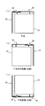
- FIG. 1 is a perspective view showing a configuration of an embodiment of a circularly polarized antenna.
- the circularly polarized antenna 1 includes a ground conductor plate 10, an inverted F antenna 20 ( ⁇ / 4 type antenna), a dipole antenna 30 ( ⁇ / 2 type antenna), and a feeding unit 40.
- the inverted F antenna 20 functions as a first linear antenna
- the dipole antenna 30 functions as a second linear antenna.
- the ground conductor plate 10 is formed of a rectangular sheet metal.
- the size of the ground conductor plate 10 is 40 mm ⁇ 40 mm.
- the inverted F antenna 20 includes an antenna main portion 21 disposed substantially parallel to the side 11 of the ground conductor plate 10, and a first short-circuit portion 22 that connects the end portion side of the antenna main portion 21 and the ground conductor plate 10. And the second short-circuit portion 23 are provided.
- the first short-circuit portion 22 connects the end portion of the antenna main portion 21 and the end portion of the ground conductor plate 10, and the second short-circuit portion 23 is substantially parallel to the antenna main portion on the open end side with respect to the first short-circuit portion 22.
- the part 21 and the ground conductor plate 10 are connected.
- the inverted F antenna 20 is formed with a line width of 1 mm as a whole, the length of the antenna main portion 21 is 32 mm, and the length of the first short-circuit portion 22 and the second short-circuit portion 23 is 4 mm (in the drawing, the antenna main portion 21 The width is added and displayed as 5 mm). With respect to the first short-circuit portion 22, the second short-circuit portion 23 is disposed with an interval of 9 mm.
- the inverted F antenna 20 of the present embodiment is integrally formed of the same material as the ground conductor plate 10, but may be formed separately and connected to each other, or may be formed of a different material. .
- the dipole antenna 30 is provided with an antenna main portion 31 disposed substantially in parallel with the other side 12 orthogonal to the side 11 of the ground conductor plate 10, and extends from the antenna main portion 31 toward the side 11.
- a bent portion 32 is provided.
- the bent portion 32 functions as an open end side facing a power supply portion 40 described later.
- the dipole antenna 30 is formed as a whole with a line width of 1 mm, the antenna main part 31 is 45 mm long, and the bent part 32 is 7 mm long.
- the distance between the antenna main portion 31 and the side 12 of the ground conductor plate 10 is 5 mm.
- the open end of the bent portion 32 and the open end of the antenna main portion 21 in the inverted F antenna 20 are arranged at a predetermined interval so that they do not come into contact with each other.
- an interval of 7 mm (not shown) ) Is opened.
- the bent portion 32 is bent so as to face the power feeding portion 40, but is not necessary when the power feeding portion 40 side is bent as will be described later, and the antenna main portion 31 is formed longer by that amount. (See FIG. 9A).
- the power feeding unit 40 is disposed in parallel with the side 11 of the ground conductor plate 10 so as to be opposed to the open end side of the inverted F antenna 20 and the open end side (bent portion 32) of the dipole antenna 30 with a predetermined distance therebetween. 41 and a power supply line 42 electrically connected to the EM power supply unit 41 at one end side. The other end side of the feed line 42 extends to the ground conductor plate 10 side, and has a feed point P1 at the end thereof.
- the power feeding unit 40 is formed to have a line width of 1 mm throughout, and the length of the EM power feeding unit 41 is formed to 17 mm (not shown), and a power feeding region of about 5 mm (not shown) on both ends or the vicinity thereof. The feed region having the value of 1 is opposed to the open end side of the inverted F antenna 20 and the dipole antenna 30 with an interval of 0.5 mm.
- a general inverted-F antenna has a short-circuited portion near the outside of the feeding point in order to facilitate impedance matching of an inverted-L antenna that is bent in the middle to lower the profile.
- the feeding point is not connected to the ground conductor plate.
- electromagnetic coupling EM coupling
- the power feeding unit 40 disposed opposite to the open end side of the antenna main part 21 and the second short circuit corresponding to the power feeding point.
- the part 23 is connected to the ground conductor plate 10.
- the EM power feeding portion 41 when the EM power feeding portion 41 is electromagnetically fed (EM feeding) to the inverted F antenna 20, a current also flows to the second short-circuit portion 23 via the antenna main portion 21, thereby causing the second short-circuit.
- the part 23 acts in the same manner as a general feeding point and functions as a general inverted F antenna as a whole. The same applies to the inverted L antenna used in FIG. 8 and FIG.
- an inverted F-type antenna 20 ( ⁇ / 4 type) and a dipole antenna 30 ( ⁇ / 2 type) are arranged orthogonally on a sheet metal and fed at one point by EM coupling. It was possible to generate an antenna, and it was possible to generate circularly polarized waves that ensure high gain (about 3 dBc), high efficiency (a little less than 90%), and good angular width.
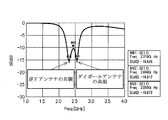
- FIG. 2 is an explanatory diagram showing the return loss characteristics of the circularly polarized antenna 1.
- the length directions of the side 11 and the side 12 of the ground conductor plate 10 are the Y axis and the X axis, respectively.
- the direction orthogonal to 10 will be described as the Z-axis direction.
- the phase difference of ⁇ / 2 is substantially obtained at f0 due to the difference ⁇ between the resonant frequencies of the inverted F antenna 20 and the dipole antenna 30. One is satisfied.
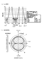
- FIG. 3 is an explanatory diagram showing the axial ratio (AR) characteristic and directivity characteristic of the circularly polarized antenna 1.
- the frequency of 3 dB or less which is an indication of good circular polarization, is 136.9 degrees to 205.6 degrees.
- BW 68.8 degrees
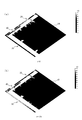
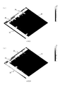
- 4 and 5 are explanatory diagrams showing the distribution state of the surface current density (2.44 GHz) of the circularly polarized antenna 1.
- T represents a period.
- the black and white state is almost black due to the image accuracy of the drawings, but the surface current density is higher as it approaches white. As shown in FIG.
- the high-frequency current only rides on the edge (near the outer periphery) of the ground conductor plate 10. That is, according to the circularly polarized antenna 1 of the present embodiment, the high frequency current does not get on the central portion of the ground conductor plate 10. Therefore, when the length of one side of the ground conductor plate 10 is L, it is possible to cut out the central L / 2 or 3L / 5 square range, or the range of the vicinity thereof. Thereby, the weight of the circularly polarized antenna 1 can be reduced. Further, since the high frequency current is not applied to the central region of the ground conductor plate 10, an electronic circuit or the like can be disposed in the region. It is also possible to cut out the central region as described above and arrange an electronic circuit or the like in the cutout region.
- the circularly polarized wave antenna 1 of the present embodiment it is formed so as to face each of the two orthogonal sides 11 and 12 of the ground conductor plate 10 and have a phase difference of approximately ⁇ / 2.
- the inverted F antenna 20 and the dipole antenna 30 are disposed so as to be substantially orthogonal.
- the EM power feeding portion 41 of the common power feeding portion 40 is disposed opposite to the open end side of the inverted F antenna 20 and the open end side of the dipole antenna 30, so that electromagnetic power feeding to both antennas 20 and 30 is performed. Is performed at one point.
- the circularly polarized antenna 1 of the present embodiment can be easily manufactured by adopting the one-point power feeding method based on the EM power feeding. Further, by using the inverted F antenna 20 and the dipole antenna 30 as the first and second linear antennas, the size can be reduced as compared with a circularly polarized antenna using a conventional patch antenna.
- FIG. 6 is an explanatory diagram showing the arrangement of the circularly polarized antenna 1 and the switching of the polarization. Except for FIG. 10A, in the drawings of FIG. 6 and the subsequent drawings, the shape and arrangement state of each antenna are described, and therefore simplified.
- FIG. 6A shows the reference circularly polarized antenna 1 which is the same as the circularly polarized antenna 1 described in FIG. With respect to this reference, as shown in FIGS. 6B and 6C, the turning direction of the circularly polarized wave can be reversed by reversing the front and back of the circularly polarized antenna 1 arranged as a reference. it can.
- FIG. 6B shows a case where they are arranged symmetrically (inverted with respect to the longitudinal center axis), and FIG.
- FIG. 6C shows a case where they are arranged symmetrically vertically (inverted with respect to the lateral center axis). is there.
- the turning direction of the circularly polarized wave (right / left) can be easily changed.
- FIG. 7 shows a configuration of a modified example of the circularly polarized antenna 1.
- FIG. 7A shows two sets of circularly polarized antennas 1 described in FIG. 1 arranged in point symmetry (on the opposite side). That is, with respect to one ground conductor plate 10, a second circular polarization antenna 1a including an inverted F antenna 20a, a dipole antenna 30a, and a power feeding unit 40a, a second antenna including an inverted F antenna 20b, a dipole antenna 30b, and a power feeding unit 40b.
- Two sets of circularly polarized antennas 1b are arranged point-symmetrically.
- the resonance frequency (for example, 2.44 GHz) of both circularly polarized antennas 1a and 1b is supplied in common and in phase, thereby gain compared to the circularly polarized antenna 1 described in the embodiment. Can be improved.
- a dual-polarized circularly polarized antenna can be provided.
- the first circularly polarized antenna 1a is set to the 2.44 GHz band
- the second circularly polarized antenna 1b is set to the 5.2 GHz band.
- FIG. 8 shows modified examples in which other types of antennas are combined.
- any one of an inverted F antenna, an inverted L antenna, and a dipole antenna can be selected, and the selectable combinations are shown in FIG.
- the inverted F antenna and the inverted L antenna are simply expressed as inverted F and inverted L
- the dipole antenna is simply expressed as a dipole.
- both ⁇ / 4 type antennas are arranged as the first linear antenna and the second linear antenna.
- FIG. 8A shows an inverted F + inverted F-type circularly polarized antenna in which two inverted F antennas are arranged so that the open end side is on the same corner side of the ground conductor plate 10.
- the open end side is bent so as to face the EM power feeding portion 41, similarly to the bent portion 32 of the dipole antenna 30 described in FIG. The same applies to the bending of the open end side of one of the antennas so as to oppose the EM feeding portion 41 in FIGS. 8B to 8E.
- FIG. 8B is an example of an inverted F + inverted L type circularly polarized antenna in which an inverted L antenna is arranged instead of the dipole antenna 30 of the embodiment. Also in this example, the feeding portion 40 side is bent with the open end side, and a short-circuit portion is provided on the opposite side.
- FIG. 8C shows an inverted L + inverted L type circularly polarized antenna in which both the inverted F antenna 20 and the dipole antenna 30 of the embodiment are replaced with an inverted L antenna. 8A to 8C, the short-circuit portions of both antennas are arranged so as to be diagonally located with respect to the ground conductor plate 10.
- FIG. 8D is an example of an inverted L + dipole circularly polarized antenna in which an inverted L antenna is arranged instead of the inverted F antenna 20 of the embodiment.
- ⁇ / 4 type and ⁇ / 2 type antennas are used as in the embodiment.
- the circularly polarized antennas according to the modified examples described in FIGS. 8A to 8D all use ⁇ / 4 type antennas (inverted F antenna and inverted L antenna).
- the conductor plate 10 is required. Further, as described with reference to FIGS. 4 and 5 for the circularly polarized antenna 1 of the embodiment, a high-frequency current is also applied to the central portion of the ground conductor plate 10 in each of the modified examples of FIGS. never ride. Therefore, also in these modified examples, the central portion of the ground conductor plate 10 can be cut out or an electronic circuit can be provided.
- FIG. 8E shows an example of a dipole + dipole circularly polarized antenna in which a dipole antenna is arranged instead of the inverted F antenna 20 of the embodiment. According to this modification, since both are ⁇ / 2 type antennas, the ground conductor plate 10 is not required, and a light-weight circularly polarized antenna can be obtained.
- each of the first circularly polarized antenna 1a and the second circularly polarized antenna 1b is an arbitrary one of FIGS. 8 (a) to 8 (e). It is also possible to select one.
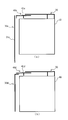
- FIG. 9 is an explanatory diagram of a modified example in which the shape of the feeding portion is changed in the circularly polarized antenna 1.
- the antenna main portion 21 of the inverted F antenna 20 and the bent portion 32 of the dipole antenna 30 are arranged on substantially the same straight line, so that a linear shape is obtained.
- the case where the EM power feeding portion 41 is disposed opposite to the open ends of both antennas has been described.
- FIG. 9 (a) the open end side of the dipole antenna 30c (second linear antenna) is not bent, and only the linear antenna main part 31c is configured, and the EM power feeding part 41c is bent instead.
- the dipole antenna 30c is disposed opposite to the open end.
- the antenna main portion 21 of the inverted F antenna 20 and the bent portion 32 of the dipole antenna 30d are not arranged on the same line but arranged in parallel with a predetermined interval,
- the EM power feeding part 41d is arranged inside. Accordingly, in the example of FIG. 9, when the side facing the ground conductor plate 10 of the EM power feeding portion 41 is the inner side and the opposite side is the outer side, the antenna main portion 21 of the inverted F antenna 20 is outside the EM feeding portion 41 d.
- the bent portion of the dipole antenna 30d faces the inside of the EM power feeding portion 41d.
- FIG. 9 (a), (b) about the shape of the open end side of both antennas (a 1st linear antenna and a 2nd linear antenna) shown in FIG. 9 (a), (b), and the shape and arrangement
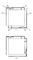
- FIG. 10 is an explanatory diagram showing the configuration of another modification of the circularly polarized antenna 1.
- FIG. 10A shows a modification of the circularly polarized antenna in which the inverted F antenna 20, the dipole antenna 30, and the power feeding unit 40 are three-dimensionally structured. As shown in FIG. 10A, the first short-circuit portion 22e and the second short-circuit portion 23e of the inverted F antenna 20e connected to the ground conductor plate 10 are bent at a right angle with respect to the ground conductor plate 10, so that Z It is formed on the -Y plane.
- the dipole antenna 30e As for the dipole antenna 30e, as described above, the central portion in the length direction where the voltage is zero is connected by the short-circuit portion 33e, and the short-circuit portion 33e is bent at a right angle with respect to the ground conductor plate 10, thereby It is formed on a plane.
- the feed line 42e Corresponding to the fact that the inverted F antenna 20e and the dipole antenna 30e are bent in a right angle direction, the feed line 42e has a three-dimensional structure so as to be orthogonal to the ground conductor plate 10 in the same manner. It is formed on the -Y plane.
- the bent portion 32e of the dipole antenna 30e has a shorter length than the embodiment described with reference to FIG. 1 due to the three-dimensional structure.
- the end portion 43e on the dipole antenna 30e side of the EM feed portion 41e is not 12 (see FIG. 1). According to the modification shown in FIG. 10A, the arrangement area of the entire circularly polarized antenna can be reduced.
- an inverted L antenna 50 and a dipole are provided as a second circularly polarized antenna further outside the inverted F antenna 20 and the dipole antenna 30 of the circularly polarized antenna described in FIG.
- An antenna 60 is provided.
- the inverted L antenna 50 forms a short-circuit portion (a feeding line portion in a general inverted-L antenna) on an extension line of the second short-circuit portion 23 of the inverted F antenna 20.
- the electric power feeding part 40 it is made to electromagnetically feed in common with two sets of circularly polarized antennas.
- a multi-frequency circularly polarized antenna can be provided.
- each circularly polarized antenna described may be formed on a substrate having a high relative dielectric constant such as glass epoxy resin. This makes it possible to provide a circularly polarized antenna that is miniaturized at the same wavelength (same resonance frequency) by utilizing the fact that the wavelength is shortened when the same size is used as a reference.
- the single-layer circularly polarized antenna has been described.
- each circular polarization of the embodiment and the modification described above on the high relative dielectric constant substrate such as a glass epoxy resin is used.
- the antenna layer may be multilayered (for example, two layers, four layers, eight layers).
- the respective portions of the ground conductor plate 10, the inverted F antenna 20, the dipole antenna 30, and the power feeding unit 40 in the polarization sharing antenna of each layer are connected to each other via.
- the power supply line 42 of the power supply unit 40 may have a single layer and may be connected to the EM power supply unit 41 of any one layer.
- the antenna has n layers, and the high-permittivity substrate has n ⁇ 1 layers. You may arrange
- the antenna element shape in a straight state is described except for the open end.
- the shape is not limited to the linear shape.
- a meander shape, a helical shape, or a bent end shape (a bent end shape) can be used.
Abstract
より容易に製造可能で小型化された円偏波アンテナを提供する。 実施形態の円偏波アンテナ1では、矩形形状の地導体板10の直交する2辺の一方の辺側に角側を開放端とする逆Fアンテナ20と、他方の辺側にダイポールアンテナ30を配設し、両開放端側に給電部40のEM給電部41を対向配置させる。逆Fアンテナ20の開放端側と反対側は、第1短絡部22、第2短絡部23により地導体板10に短絡接続されている。このように、逆Fアンテナ20(λ/4型)と、ダイポールアンテナ30(λ/2型)を板金上に直交に配置し、EM結合による1点給電した結果、容易に製造可能な円偏波アンテナとすることができ、また高利得(約3dBc)、高効率(90%弱)、良好な角度幅、を確保する円偏波を発生させることができた。
Description
本発明は、円偏波アンテナに係り、2つのアンテナを用いた円偏波アンテナに関する。
GPS衛星やBS放送などの各種通信方式において、円偏波による通信が広く行われており、その通信には円偏波アンテナが使用される。
従来の円偏波アンテナとしては、縮退分離法を用いたマイクロストリップアンテナがある。この円偏波アンテナは、正方形のマイクロストリップアンテナの2つの角の一部を切り取った形状のアンテナであり、特許文献1の図10に示されている。
また、2点給電方式による円偏波アンテナとして、正方形のマイクロストリップアンテナの直交する2辺に対し、別々に給電することで円偏波とするアンテナがある。この方式では、方形または円形マイクロストリップアンテナを空間的に直交する2つの給電点で位相差がπ/2となるように給電するものである。
従来の円偏波アンテナとしては、縮退分離法を用いたマイクロストリップアンテナがある。この円偏波アンテナは、正方形のマイクロストリップアンテナの2つの角の一部を切り取った形状のアンテナであり、特許文献1の図10に示されている。
また、2点給電方式による円偏波アンテナとして、正方形のマイクロストリップアンテナの直交する2辺に対し、別々に給電することで円偏波とするアンテナがある。この方式では、方形または円形マイクロストリップアンテナを空間的に直交する2つの給電点で位相差がπ/2となるように給電するものである。
しかし、マイクロストリップアンテナを使用する場合には、アンテナ一辺のサイズがλg/2であると共にアンテナよりも大きな誘電体基板が必要になるため、全体として大サイズになってしまうという問題がある。ここでλgは、誘電体基板内での波長である。
一方、2点給電方式の円偏波アンテナでは、2点で給電するための二分配回路などの外部回路が必要であり、給電系が複雑になるという問題がある。
一方、2点給電方式の円偏波アンテナでは、2点で給電するための二分配回路などの外部回路が必要であり、給電系が複雑になるという問題がある。
本発明は、より容易に製造可能で小型化された円偏波アンテナを提供することを目的とする。
(1)請求項1に記載の発明では、少なくとも1の開放端を有する第1線状アンテナと、少なくとも1の開放端を有し、当該開放端側と前記第1線状アンテナの開放端側とが所定間隔で、前記第1線状アンテナとほぼ直交状態に配設され、円偏波を実現する周波数において、前記第1線状アンテナとの位相差が実質π/2となる第2線状アンテナと、前記第1線状アンテナの前記開放端側、及び前記第2線状アンテナの前記開放端側のそれぞれと、所定間隔をおいて対向配置されることで、前記第1線状アンテナ及び前記第2線状アンテナに電磁的に接続されるEM給電部と、前記EM給電部と電気的に接続され、前記EM給電部を介して前記第1線状アンテナ及び前記第2線状アンテナに給電する給電ラインと、を具備したことを特徴とする円偏波アンテナを提供する。
(2)請求項2に記載の発明では、地導体板を更に備え、前記第1線状アンテナは、前記地導体板の端面とほぼ平行に配設され、開放端側が前記EM給電部と対向配置されるアンテナ主部と、前記アンテナ主部の前記開放端側の反対側端部と前記地導体板とを短絡する第1短絡部と、前記アンテナ主部の前記第1短絡部よりも開放側において、前記アンテナ主部と前記地導体板とを短絡する第2短絡部と、を有する逆Fアンテナである、ことを特徴とする請求項1に記載の円偏波アンテナを提供する。
(3)請求項3に記載の発明では、地導体板を更に備え、前記第1線状アンテナは、前記地導体板の端面とほぼ平行に配設され、開放端側が前記EM給電部と対向配置されるアンテナ主部と、前記アンテナ主部の前記開放端側の反対側端部と前記地導体板とを短絡する第1短絡部と、を有する逆Lアンテナである、ことを特徴とする請求項1に記載の円偏波アンテナを提供する。
(4)請求項4に記載の発明では、前記第1線状アンテナは、ダイポールアンテナである、ことを特徴とする請求項1から請求項3のうちのいずれか1の請求項に記載の円偏波アンテナを提供する。
(5)請求項5に記載の発明では、前記第2線状アンテナは、ダイポールアンテナ、逆Fアンテナ、又は、逆Lアンテナである、ことを特徴とする請求項1から請求項4のうちのいずれか1の請求項に記載の円偏波アンテナを提供する。
(6)請求項6に記載の発明では、当該円偏波アンテナにおける円偏波の共振周波数fに対し、前記第1線状アンテナの共振周波数f1と前記第2線状アンテナの共振周波数f2の差δが、0.07f~0.13fである、ことを特徴とする請求項1から請求項5のうちのいずれか1の請求項に記載の円偏波アンテナを提供する。
(7)請求項7に記載の発明では、前記差δは、0.1fである、ことを特徴とする請求項6に記載の円偏波アンテナを提供する。
(8)請求項8に記載の発明では、前記円偏波の共振周波数f0がf0=2.44GHzで、前記第1線状アンテナの共振周波数f1がf1=2.31GHz、前記第2線状アンテナの共振周波数f2がf2=2.55GHzである、ことを特徴とする請求項1から請求項7のうちのいずれか1の請求項に記載の円偏波アンテナを提供する。
(9)請求項9に記載の発明では、高比誘電体基板を備え、前記第1線状アンテナと前記第2線状アンテナは、前記高比誘電体基板上に形成されている、ことを特徴とする請求項1から請求項8のうちのいずれか1の請求項に記載の円偏波アンテナを提供する。
(10)請求項10に記載の発明では、前記第1線状アンテナ、前記第2線状アンテナ、及び前記EM給電部のそれぞれは、互いにビア接続された複数層で形成されている、ことを特徴とする請求項1から請求項9のうちのいずれか1の請求項に記載の円偏波アンテナを提供する。
(11)請求項11に記載の発明では、前記第1線状アンテナ及び前記第2線状アンテナは、アンテナエレメント部分の形状が、直線形状、ミアンダ形状、ヘリカル形状、又は、先端折れ曲げ形状、である、ことを特徴とする請求項1から請求項10のうちのいずれか1の請求項に記載の円偏波アンテナを提供する。
本発明によれば、第1線状アンテナの開放端部と第2線状アンテナの開放端部のそれぞれと、所定間隔をおいて対向配置されるEM給電部による1点給電とすることで、容易に製造可能となる。
また、第1及び第2線状アンテナを用いることで小型化することが可能である。
また、第1及び第2線状アンテナを用いることで小型化することが可能である。
以下、本発明の円偏波アンテナにおける好適な実施の形態について、図1から図10を参照して詳細に説明する。
(1)実施形態の概要
本実施形態の円偏波アンテナでは、ダイポールアンテナ、逆Fアンテナ、逆Lアンテナの何れかからなる、第1線状アンテナと第2線状アンテナとを使用し、両線状アンテナの開放端側を所定距離隔てて直交配置する。第1線状アンテナと第2線状アンテナとは、円偏波を実現する周波数において、位相差が実質π/2となるように調整されている。
そして、第1線状アンテナと第2線状アンテナの両開放端側のそれぞれと、所定間隔をおいてEM給電部を対向配置し、このEM給電部に給電ラインを電気的に接続する。
このように、本実施形態の円偏波アンテナによれば、2つの直交する線状アンテナの両開放端側から、電磁的な1点給電を実現することで、容易に製造可能で小型化された円偏波アンテナが得られる。
ここで、アンテナの直交配置は、直交状態に配置することで、この直交状態の配置は、厳密な意味での直角にかぎられず、実用のアンテナとしての良好な使用目安である軸比3dB以下が実現できる程度の角度の幅を含むものとする。
具体的には、矩形形状の地導体板10の直交する2辺の一方の辺側に角側を開放端とする逆Fアンテナ20(第1線状アンテナ)と、他方の辺側にダイポールアンテナ30(第2線状アンテナ)を配設し、両開放端側に給電部40のEM給電部41を対向配置させる。
逆Fアンテナ20の開放端側の反対側は、第1短絡部22、第2短絡部23により地導体板10に短絡接続されている。
ダイポールアンテナ30は、地導体板10に短絡接続されることはないが、全長の中央部での電圧がゼロであることから、この中央部で地導体板10に接続することは可能である。
逆Fアンテナ20の開放端側の反対側は、第1短絡部22、第2短絡部23により地導体板10に短絡接続されている。
ダイポールアンテナ30は、地導体板10に短絡接続されることはないが、全長の中央部での電圧がゼロであることから、この中央部で地導体板10に接続することは可能である。
円偏波アンテナ1は、その共振周波数をf0とした場合に、逆Fアンテナ20の共振周波数f1とダイポールアンテナ30の共振周波数f2の差δ(=f2-f1)の絶対値が、0.07f~0.13fの範囲、例えばδ=0.1とすることで、f0において位相差がほぼπ/2となるように形成される。ここで、ほぼπ/2の位相差とは、π/2を含み、実用のアンテナとしての良好な使用目安である軸比3dB以下が実現できる程度の位相差の幅を含むものとする。
例えば、円偏波の共振周波数f0をf0=2.44GHzとした場合、逆Fアンテナ20の共振周波数f1がf1=2.31GHz、ダイポールアンテナ30の共振周波数f2がf2=2.55GHzとすることで、好適な円偏波アンテナが形成される。
例えば、円偏波の共振周波数f0をf0=2.44GHzとした場合、逆Fアンテナ20の共振周波数f1がf1=2.31GHz、ダイポールアンテナ30の共振周波数f2がf2=2.55GHzとすることで、好適な円偏波アンテナが形成される。
(2)実施形態の詳細
図1は円偏波アンテナにおける実施形態の構成を表した斜視図である。
図1に示すように円偏波アンテナ1は、地導体板10と、逆Fアンテナ20(λ/4型アンテナ)と、ダイポールアンテナ30(λ/2型アンテナ)と、更に、給電部40を備えている。
逆Fアンテナ20は第1線状アンテナとして機能し、ダイポールアンテナ30は第2線状アンテナとして機能している。
地導体板10は、矩形形状の板金により形成されている。地導体板10のサイズは、40mm×40mmである。
図1は円偏波アンテナにおける実施形態の構成を表した斜視図である。
図1に示すように円偏波アンテナ1は、地導体板10と、逆Fアンテナ20(λ/4型アンテナ)と、ダイポールアンテナ30(λ/2型アンテナ)と、更に、給電部40を備えている。
逆Fアンテナ20は第1線状アンテナとして機能し、ダイポールアンテナ30は第2線状アンテナとして機能している。
地導体板10は、矩形形状の板金により形成されている。地導体板10のサイズは、40mm×40mmである。
逆Fアンテナ20は、地導体板10の辺11とほぼ平行に配設されたアンテナ主部21と、このアンテナ主部21の端部側と地導体板10とを接続する第1短絡部22と第2短絡部23の2つの短絡部を備えている。第1短絡部22は、アンテナ主部21の端部と地導体板10の端部とを接続し、第2短絡部23は、第1短絡部22よりも開放端側でほぼ平行にアンテナ主部21と地導体板10とを接続している。
逆Fアンテナ20は、全体として線幅1mmに形成され、アンテナ主部21の長さが32mm、第1短絡部22と第2短絡部23の長さが4mm(図面では、アンテナ主部21の幅を加えて5mmと表示)である。
第1短絡部22に対して、第2短絡部23は9mmの間隔を開けて配設されている。
本実施形態の逆Fアンテナ20は、地導体板10と同一材料により一体形成されているが、別々に形成され両者を接続するようにしてもよく、また別材料で形成するようにしてもよい。
逆Fアンテナ20は、全体として線幅1mmに形成され、アンテナ主部21の長さが32mm、第1短絡部22と第2短絡部23の長さが4mm(図面では、アンテナ主部21の幅を加えて5mmと表示)である。
第1短絡部22に対して、第2短絡部23は9mmの間隔を開けて配設されている。
本実施形態の逆Fアンテナ20は、地導体板10と同一材料により一体形成されているが、別々に形成され両者を接続するようにしてもよく、また別材料で形成するようにしてもよい。
ダイポールアンテナ30は、地導体板10の辺11と直交する他の一辺12とほぼ平行に配設されたアンテナ主部31と、このアンテナ主部31から、辺11方向に向けて延設された屈曲部32を備えている。なお、屈曲部32は後述の給電部40と対向する開放端側として機能している。
ダイポールアンテナ30は、全体として線幅1mmに形成され、アンテナ主部31の長さが45mmに、屈曲部32の長さが7mmに形成されている。アンテナ主部31と地導体板10の辺12との間隔は5mmである。
屈曲部32の開放端と、逆Fアンテナ20におけるアンテナ主部21の開放端とは、両者が接触しないように所定間隔を開けて配置されており、本実施形態では、7mmの間隔(図示しない)が開けられている。
なお、屈曲部32は、給電部40と対向させるために屈曲しているが、後述のように給電部40側が屈曲している場合には不要であり、その分アンテナ主部31を長く形成する(図9(a)参照)。
ダイポールアンテナ30は、全体として線幅1mmに形成され、アンテナ主部31の長さが45mmに、屈曲部32の長さが7mmに形成されている。アンテナ主部31と地導体板10の辺12との間隔は5mmである。
屈曲部32の開放端と、逆Fアンテナ20におけるアンテナ主部21の開放端とは、両者が接触しないように所定間隔を開けて配置されており、本実施形態では、7mmの間隔(図示しない)が開けられている。
なお、屈曲部32は、給電部40と対向させるために屈曲しているが、後述のように給電部40側が屈曲している場合には不要であり、その分アンテナ主部31を長く形成する(図9(a)参照)。
給電部40は、地導体板10の辺11と平行に、逆Fアンテナ20の開放端側とダイポールアンテナ30の開放端側(屈曲部32)と所定間隔を開けて対向配置されたEM給電部41と、このEM給電部41と一端側が電気的に接続される給電ライン42を備えている。給電ライン42の他端側は、地導体板10側に延び、その端部に給電ポイントP1を有している。
給電部40は、全体を通して線幅1mmに形成され、EM給電部41の長さは17mm(図示せず)に形成され、両端側の約5mm(図示せず)の給電領域、又は、その近傍の値を有する給電領域が、それぞれ逆Fアンテナ20とダイポールアンテナ30の開放端側と、0.5mmの間隔を開けて対向している。
給電部40は、全体を通して線幅1mmに形成され、EM給電部41の長さは17mm(図示せず)に形成され、両端側の約5mm(図示せず)の給電領域、又は、その近傍の値を有する給電領域が、それぞれ逆Fアンテナ20とダイポールアンテナ30の開放端側と、0.5mmの間隔を開けて対向している。
なお、一般の逆Fアンテナは、モノポールアンテナを途中で折り曲げて低姿勢化した逆Lアンテナのインピーダンス整合をとりやすくするために、給電点の外側付近に短絡部を設けたものである。そして、給電点は地導体板に接続されない。
これに対して本実施形態の逆Fアンテナ20では、アンテナ主部21の開放端側に対向配置された給電部40で電磁的に結合(EM結合)すると共に、給電点に対応する第2短絡部23が地導体板10に接続されている。
しかし、本実施形態ではEM給電部41から逆Fアンテナ20に電磁給電(EM給電)されることで、アンテナ主部21を介して第2短絡部23にも電流が流れることで、第2短絡部23が一般の給電点と同様に作用し、全体として通常の逆Fアンテナと同様に機能している。
この点、後述する図8や図10(b)で使用する逆Lアンテナについても同様である。
これに対して本実施形態の逆Fアンテナ20では、アンテナ主部21の開放端側に対向配置された給電部40で電磁的に結合(EM結合)すると共に、給電点に対応する第2短絡部23が地導体板10に接続されている。
しかし、本実施形態ではEM給電部41から逆Fアンテナ20に電磁給電(EM給電)されることで、アンテナ主部21を介して第2短絡部23にも電流が流れることで、第2短絡部23が一般の給電点と同様に作用し、全体として通常の逆Fアンテナと同様に機能している。
この点、後述する図8や図10(b)で使用する逆Lアンテナについても同様である。
以上のように構成された円偏波アンテナについてのシミュレーションを行った結果について説明する。
すなわち、逆F型アンテナ20(λ/4型)と、ダイポールアンテナ30(λ/2型)を板金上に直交に配置し、EM結合による1点給電した結果、容易に製造可能な円偏波アンテナとすることができ、また高利得(約3dBc)、高効率(90%弱)、良好な角度幅、を確保する円偏波を発生させることができた。
すなわち、逆F型アンテナ20(λ/4型)と、ダイポールアンテナ30(λ/2型)を板金上に直交に配置し、EM結合による1点給電した結果、容易に製造可能な円偏波アンテナとすることができ、また高利得(約3dBc)、高効率(90%弱)、良好な角度幅、を確保する円偏波を発生させることができた。
図2は、円偏波アンテナ1のリターンロス特性を表した説明図である。
なお、以下に説明する円偏波アンテナ1の特性については、図1に示したように、地導体板10の辺11と辺12の長さ方向をそれぞれY軸、X軸とし、地導体板10と直交する方向をZ軸方向として説明する。
図2に示されるように、円偏波アンテナ1の共振周波数f0(M02)=2.440GHzに対して、逆Fアンテナ20の共振周波数がf1(M01)=2.310GHz、ダイポールアンテナ30の共振周波数がf2(M03)=2.550GHzである。
このように、2つの線状アンテナの共振周波数の差δ(=f2-f1)は、円偏波アンテナ1の共振周波数f0の7%~13%の範囲に形成され、好ましくは約10%に形成される。
そして、本実施形態の円偏波アンテナ1では、逆Fアンテナ20とダイポールアンテナ30の共振周波数の差δによって、f0において実質π/2の位相差を持つことで、円偏波発生条件の1つが満たされている。
図3は、円偏波アンテナ1の軸比(AR)特性と指向性特性を表した説明図である。
図3は、共振周波数2.44GHzにおける、Z-X面(φ=0°)について、(a)が軸比特性を、(b)が指向性特性を表している。
図3(a)において、斜線領域で示したように、本実施形態の円偏波アンテナ1では、良好な円偏波の目安である3dB以下の周波数が、136.9度~205.6度(BW=68.8度)と、333.7度~43.3度(BW=69.6度)であり、良好な角度幅が得られていることがわかる。
図3は、共振周波数2.44GHzにおける、Z-X面(φ=0°)について、(a)が軸比特性を、(b)が指向性特性を表している。
図3(a)において、斜線領域で示したように、本実施形態の円偏波アンテナ1では、良好な円偏波の目安である3dB以下の周波数が、136.9度~205.6度(BW=68.8度)と、333.7度~43.3度(BW=69.6度)であり、良好な角度幅が得られていることがわかる。
なお、図3(a)の軸比特性では示していないが、Z-X面(φ=0°)において、AR≦3dBとなる角度幅が30°以上となる周波数範囲は、2.38~2.47GHz(比帯域幅=約3.7%)となっている。
一方、図3(b)に示した指向性特性によれば、点線で囲った領域A、Bで示されるように、±Z方向(地導体板10に垂直な方向)に最大放射方向を持ち、その方向にEθ成分とEφ成分で利得差がほとんど存在しない。これにより、本実施形態の円偏波アンテナ1は円偏波発生条件の1を満たしていることが示されている。
また、図3(b)に示したように、本実施形態の円偏波アンテナ1では、放射効率=89.3%と高効率が確保されている。
また、図3(b)に示したように、本実施形態の円偏波アンテナ1では、放射効率=89.3%と高効率が確保されている。
図4、図5は、円偏波アンテナ1の面電流密度(2.44GHz)の分布状態を表した説明図である。
図4(a)、(b)が円偏波アンテナ1のt=0とt=T/4における面電流密度を表し、図5(c)、(d)がt=T/2とt=3T/4における面電流密度を表したもので、それぞれの位相が90度ずれた状態を表している。ここでTは周期を示す。
なお、図4、5では、図面の画像精度の関係でほぼ白黒状態になっているが、白に近づくほど面電流密度が高い状態を表している。
図4(a)に示されるように、t=0では、逆Fアンテナ20の面電流密度が高く、ダイポールアンテナ30の面電流密度が低い。
t=T/4では、図4(b)に示されるように、逆Fアンテナ20の面電流密度が低く、ダイポールアンテナ30の面電流密度が高い。
さらにt=T/2では、図5(c)に示されるように、逆Fアンテナ20の面電流密度が高く、ダイポールアンテナ30の面電流密度が低い。
さらにt=3T/4では、図5(d)に示されるように、逆Fアンテナ20の面電流密度が低く、ダイポールアンテナ30の面電流密度が高い。
このように、円偏波アンテナ1では、逆Fアンテナ20とダイポールアンテナ30とが、π/2の位相差を持つことで、円偏波が発生していることが示される。
また、図4(a)~図5(d)で示した時間において、地導体板10に発生している面電流密度をみると、図示していない他の時間を含めたいずれの時間においても、地導体板10のエッジ(外周辺近傍)に高周波電流が乗るだけである。
即ち、本実施形態の円偏波アンテナ1によれば、地導体板10の中央部分に高周波電流が乗ることはない。
従って、地導体板10の一辺の長さをLとした場合、中央のL/2若しくは3L/5四方の範囲、又はその近傍領域の範囲を切り取ることが可能である。これにより、円偏波アンテナ1の重量を軽くすることが可能である。
また、地導体板10の当該中央領域に高周波電流が乗らないことから、当該領域内に電子回路等を配設することも可能である。上述のように中央領域を切り取って、切り取り領域内に電子回路等を配設することも可能である。
即ち、本実施形態の円偏波アンテナ1によれば、地導体板10の中央部分に高周波電流が乗ることはない。
従って、地導体板10の一辺の長さをLとした場合、中央のL/2若しくは3L/5四方の範囲、又はその近傍領域の範囲を切り取ることが可能である。これにより、円偏波アンテナ1の重量を軽くすることが可能である。
また、地導体板10の当該中央領域に高周波電流が乗らないことから、当該領域内に電子回路等を配設することも可能である。上述のように中央領域を切り取って、切り取り領域内に電子回路等を配設することも可能である。
以上説明したように、本実施形態の円偏波アンテナ1によれば、地導体板10の直交する2辺11、12のそれぞれに対向させて、ほぼπ/2の位相差を有するように形成された逆Fアンテナ20とダイポールアンテナ30を実質直交するように配設する。
そして、逆Fアンテナ20の開放端側とダイポールアンテナ30の開放端側のそれぞれに共通の給電部40のEM給電部41を対向配置することで、両アンテナ20、30に対して電磁的な給電を1点で行う。
このように本実施形態の円偏波アンテナ1では、EM給電による1点給電方式を採用することで、容易に製造可能となる。
また、第1及び第2線状アンテナとして、逆Fアンテナ20とダイポールアンテナ30を使用することで、従来のパッチアンテナを使用した円偏波アンテナにくらべて小型化することができる。
そして、逆Fアンテナ20の開放端側とダイポールアンテナ30の開放端側のそれぞれに共通の給電部40のEM給電部41を対向配置することで、両アンテナ20、30に対して電磁的な給電を1点で行う。
このように本実施形態の円偏波アンテナ1では、EM給電による1点給電方式を採用することで、容易に製造可能となる。
また、第1及び第2線状アンテナとして、逆Fアンテナ20とダイポールアンテナ30を使用することで、従来のパッチアンテナを使用した円偏波アンテナにくらべて小型化することができる。
図6は、円偏波アンテナ1の配置と偏波の入れ替えについて表した説明図である。
なお、図10(a)を除き、図6以下の図面では、各アンテナの形状や配置状態を説明するものなので、簡略化して表している。
図6(a)は、図1で説明した円偏波アンテナ1と同じで、基準となる円偏波アンテナ1を表している。
この基準に対し、図6(b)、(c)に示すように、基準配置した円偏波アンテナ1に対して裏表を反対にすることで、円偏波の旋回方向を逆にすることができる。図6(b)は、左右対称に配置(縦中心軸線に対して裏表を反転)した場合で、図6(c)は上下対称に配置(横中心軸線に対して裏表を反転)した場合である。
このように本実施形態の円偏波アンテナ1によれば、円偏波の旋回方向(右旋/左旋)を容易に変更することができる。
次に、円偏波アンテナ1における変形例について説明する。
図7は、円偏波アンテナ1の変形例の構成を表したものである。
図7(a)は、図1で説明した円偏波アンテナ1の2組みを、点対称(反対側)に配置したものである。
すなわち、1つの地導体板10に対し、逆Fアンテナ20aとダイポールアンテナ30aと給電部40aからなる第1円偏波アンテナ1aと、逆Fアンテナ20bとダイポールアンテナ30bと給電部40bからなる第2円偏波アンテナ1bの2組を点対称に配置したものである。
この変形例によれば、両円偏波アンテナ1a、1bの共振周波数(例えば、2.44GHz)を共通、かつ同相で給電することで、実施形態で説明した円偏波アンテナ1に比べて利得を向上させることができる。
一方、第1円偏波アンテナ1aと第2円偏波アンテナ1bを、それぞれ異なる周波数帯のアンテナとすることで、2周波共用の円偏波アンテナを提供することができる。例えば、第1円偏波アンテナ1aを2.44GHz帯とし、第2円偏波アンテナ1bを5.2GHz帯とする。
なお、2組の円偏波アンテナを図7(b)に示したように配置した場合には、円偏波の旋回方向が逆向きになり相殺されてしまうため、採用できない配置であるが、2つの組をスイッチングなどで異なるタイミングで給電を行えば、旋回方向(右旋/左旋)を容易に変更することができる。また、2組の円偏波アンテナの共振周波数が十分に離れている場合には、異なる2つの周波数の逆旋偏波を形成することができる。
図8は、他種類のアンテナを組み合わせた各変形例を表したものである。
第1線状アンテナと第2線状アンテナとしては、それぞれ逆Fアンテナ、逆Lアンテナ、ダイポールアンテナの何れかを選択することが可能であり、その選択可能な組み合わせを図8で表している。なお図面では、逆Fアンテナと逆Lアンテナを簡略して逆F、逆Lと表記し、ダイポールアンテナをダイポールと簡略して表記している。
図8(a)~(c)は、第1の線状アンテナ、第2の線状アンテナとして、共にλ/4型のアンテナを配置したものである。
図8(a)は、開放端側が地導体板10の同一の角側に来るように、2つの逆Fアンテナを配置した、逆F+逆F型の円偏波アンテナである。
一方の逆Fアンテナについては、図1で説明したダイポールアンテナ30の屈曲部32と同様に、EM給電部41と対向するように開放端側を屈曲形成している。このEM給電部41に対向させるために一方のアンテナの開放端側を屈曲形成することについては図8(b)~(e)も同様である。
図8(b)は、実施形態のダイポールアンテナ30に変えて逆Lアンテナを配置した、逆F+逆L型の円偏波アンテナの例である。この例においても、給電部40側を開放端側として屈曲形成し、反対側に短絡部を設けている。
図8(c)は、実施形態の逆Fアンテナ20と、ダイポールアンテナ30の両者を、共に逆Lアンテナに変えて配置した、逆L+逆L型の円偏波アンテナである。
図8(a)~(c)共に、両アンテナの短絡部のそれぞれが、地導体板10に対して対角線上に位置するように配置されている。
図8(c)は、実施形態の逆Fアンテナ20と、ダイポールアンテナ30の両者を、共に逆Lアンテナに変えて配置した、逆L+逆L型の円偏波アンテナである。
図8(a)~(c)共に、両アンテナの短絡部のそれぞれが、地導体板10に対して対角線上に位置するように配置されている。
図8(d)は、実施形態の逆Fアンテナ20に変えて逆Lアンテナを配置した、逆L+ダイポール型の円偏波アンテナの例である。この変形例では、実施形態と同様にλ/4型とλ/2型のアンテナ使用している。
なお、図8(a)~(d)で説明した各変形例にかかる円偏波アンテナでは、いずれもλ/4型のアンテナ(逆Fアンテナ、逆Lアンテナ)を使用しているため、地導体板10が必要になる。
そして、実施形態の円偏波アンテナ1に対して図4、図5で説明したと同様に、図8(a)~(d)の各変形例における地導体板10の中央部にも高周波電流が乗ることはない。従って、これらの変形例においても、地導体板10の中央部を切り取ったり、電子回路を配設したりすることができる。
そして、実施形態の円偏波アンテナ1に対して図4、図5で説明したと同様に、図8(a)~(d)の各変形例における地導体板10の中央部にも高周波電流が乗ることはない。従って、これらの変形例においても、地導体板10の中央部を切り取ったり、電子回路を配設したりすることができる。
図8(e)は、実施形態の逆Fアンテナ20に変えて、ダイポールアンテナを配置した、ダイポール+ダイポール型の円偏波アンテナの例である。
この変形例によれば、共にλ/2型のアンテナであるため、地導体板10が不要になり、軽量の円偏波アンテナとすることが可能である。
この変形例によれば、共にλ/2型のアンテナであるため、地導体板10が不要になり、軽量の円偏波アンテナとすることが可能である。
以上、図8(a)~(e)に示した各変形例の円偏波アンテナについて説明したが、その配置を図6で説明したように変更することで円偏波の旋回方向を選択することができる。
また、図7とその変形(多周波)で説明したように、第1円偏波アンテナ1a、第2円偏波アンテナ1bの、いずれも図8(a)~(e)のうちの任意の1つを選択することも可能である。
また、図7とその変形(多周波)で説明したように、第1円偏波アンテナ1a、第2円偏波アンテナ1bの、いずれも図8(a)~(e)のうちの任意の1つを選択することも可能である。
図9は、円偏波アンテナ1における、給電部分の形状を変更した変形例についての説明図である。
図1で説明した実施形態の円偏波アンテナ1では、逆Fアンテナ20のアンテナ主部21と、ダイポールアンテナ30の屈曲部32とが、ほぼ同一直線上に配置されることで、直線状のEM給電部41を両アンテナの開放端側に対向配置する場合について説明した。
図9(a)では、ダイポールアンテナ30c(第2線状アンテナ)の開放端側を屈曲せずに、直線形状のアンテナ主部31cだけで構成し、その代わりにEM給電部41cを屈曲させることで、ダイポールアンテナ30cの開放端に対向配置したものである。
図9(b)では、逆Fアンテナ20のアンテナ主部21と、ダイポールアンテナ30dの屈曲部32とを同一線上に配置せずに、所定間隔を開けて平行に配置すると共に、当該所定間隔の内にEM給電部41dを配置したものである。これにより、図9の例では、EM給電部41の地導体板10と対向する側を内側、反対側を外側とした場合に、逆Fアンテナ20のアンテナ主部21はEM給電部41dの外側と対向し、ダイポールアンテナ30dの屈曲部はEM給電部41dの内側と対向することになる。
なお、図9(a)、(b)に示した、両アンテナ(第1線状アンテナと第2線状アンテナ)の開放端側の形状及びEM給電部の形状と配置については、図7、図8で説明した各変形例、及び、この後に説明する変形例についても同様に適用が可能である。
図10は、円偏波アンテナ1の他の変形例の構成を表した説明図である。
図10(a)は、逆Fアンテナ20、ダイポールアンテナ30、給電部40を立体構造にした円偏波アンテナの変形例である。
図10(a)に示すように、地導体板10と接続されている逆Fアンテナ20eの第1短絡部22eと第2短絡部23eを地導体板10に対して直角に折り曲げることで、Z-Y平面上に形成している。
ダイポールアンテナ30eについては、上述したように電圧がゼロである長さ方向の中央部分を短絡部33eで接続し、当該短絡部33eを地導体板10に対して直角に折り曲げることで、Z-X平面上に形成している。
また、逆Fアンテナ20eとダイポールアンテナ30eを直角方向に折り曲げたことに対応して、給電部40eについても同様に、地導体板10に対して直交するように給電ライン42eを立体構造とし、Z-Y平面上に形成している。
なお、ダイポールアンテナ30eの屈曲部32eについては、立体構造にしたことに伴い、図1で説明した実施形態に比べて長さが短くなっている。この屈曲部32eを短くしたことに対応して、ダイポールアンテナ30eのEM給電部41eとの対向する長さが短くならないようにするため、EM給電部41eのダイポールアンテナ30e側の端部43eを辺12(図1参照)方向に屈曲させている。
この図10(a)に示した変形例によれば、円偏波アンテナ全体の配設面積を小さくすることができる。
一方、図10(b)の変形例では、図1で説明した円偏波アンテナの逆Fアンテナ20とダイポールアンテナ30の更に外側に、第2の円偏波アンテナとして、逆Lアンテナ50とダイポールアンテナ60を配設したものである。
図10(b)に示すように、逆Lアンテナ50は、逆Fアンテナ20の第2短絡部23の延長線上に、短絡部(一般の逆Lアンテナにおける給電ライン部分)を形成する。
なお、給電部40については、2組の円偏波アンテナに共通して電磁給電するようにしている。
この変形例によれば、多周波の円偏波アンテナを提供することができる。
図10(b)に示すように、逆Lアンテナ50は、逆Fアンテナ20の第2短絡部23の延長線上に、短絡部(一般の逆Lアンテナにおける給電ライン部分)を形成する。
なお、給電部40については、2組の円偏波アンテナに共通して電磁給電するようにしている。
この変形例によれば、多周波の円偏波アンテナを提供することができる。
以上本実施形態の円偏波アンテナ1とその変形例について説明したが、更に各種の変形をすることが可能である。
例えば、説明した各円偏波アンテナを、ガラスエポキシ樹脂等の比誘電率が高い基板上に形成するようにしてもよい。これにより、同一サイズを基準にした場合の波長が短縮することを利用し、同一波長(同一共振周波数)で小型化した円偏波アンテナを提供することが可能になる。
例えば、説明した各円偏波アンテナを、ガラスエポキシ樹脂等の比誘電率が高い基板上に形成するようにしてもよい。これにより、同一サイズを基準にした場合の波長が短縮することを利用し、同一波長(同一共振周波数)で小型化した円偏波アンテナを提供することが可能になる。
また、説明した実施形態及び変形例では、いずれも単層の円偏波アンテナについて説明したが、ガラスエポキシ樹脂等の高比誘電率基板の上に説明した実施形態、変形例の各円偏波アンテナを配設した組を1層のアンテナ層とした場合に、当該アンテナ層を多層化(例えば2層、4層、8層)するようにしてもよい。
この場合、各層の偏波共用アンテナにおける、地導体板10、逆Fアンテナ20、ダイポールアンテナ30、及び、給電部40の各部については、相互にビア接続する。但し、給電部40の給電ライン42については、1層とし、何れか1の層のEM給電部41に接続する構成としてもよい。
なお、多層化する場合、最下層の高比誘電率基板を省略することで、アンテナをn層、高比誘電率基板をn-1層とすることで、多層化した円偏波アンテナの両外側面にアンテナ層がくるように配置してもよい。
この場合、各層の偏波共用アンテナにおける、地導体板10、逆Fアンテナ20、ダイポールアンテナ30、及び、給電部40の各部については、相互にビア接続する。但し、給電部40の給電ライン42については、1層とし、何れか1の層のEM給電部41に接続する構成としてもよい。
なお、多層化する場合、最下層の高比誘電率基板を省略することで、アンテナをn層、高比誘電率基板をn-1層とすることで、多層化した円偏波アンテナの両外側面にアンテナ層がくるように配置してもよい。
また、説明した実施形態、変形例では、いずれも開放端を除き直線状態のアンテナエレメント形状について説明したが、直線形状には限られない。
例えば、ミアンダ形状やヘリカル形状、更に端部屈曲形状(先端折れ曲げ形状)とすることも可能である。
例えば、ミアンダ形状やヘリカル形状、更に端部屈曲形状(先端折れ曲げ形状)とすることも可能である。
1 円偏波アンテナ
10 地導体板
11、12 辺
20 逆Fアンテナ
21 アンテナ主部
22 第1短絡部
23 第2短絡部
30 ダイポールアンテナ
31 アンテナ主部
32 屈曲部
40 給電部
41 EM給電部
42 給電ライン
10 地導体板
11、12 辺
20 逆Fアンテナ
21 アンテナ主部
22 第1短絡部
23 第2短絡部
30 ダイポールアンテナ
31 アンテナ主部
32 屈曲部
40 給電部
41 EM給電部
42 給電ライン
Claims (11)
- 少なくとも1の開放端を有する第1線状アンテナと、
少なくとも1の開放端を有し、当該開放端側と前記第1線状アンテナの開放端側とが所定間隔で、前記第1線状アンテナとほぼ直交状態に配設され、円偏波を実現する周波数において、前記第1線状アンテナとの位相差が実質π/2となる第2線状アンテナと、
前記第1線状アンテナの前記開放端側、及び前記第2線状アンテナの前記開放端側のそれぞれと、所定間隔をおいて対向配置されることで、前記第1線状アンテナ及び前記第2線状アンテナに電磁的に接続されるEM給電部と、
前記EM給電部と電気的に接続され、前記EM給電部を介して前記第1線状アンテナ及び前記第2線状アンテナに給電する給電ラインと、
を具備したことを特徴とする円偏波アンテナ。 - 地導体板を更に備え、
前記第1線状アンテナは、前記地導体板の端面とほぼ平行に配設され、開放端側が前記EM給電部と対向配置されるアンテナ主部と、前記アンテナ主部の前記開放端側の反対側端部と前記地導体板とを短絡する第1短絡部と、前記アンテナ主部の前記第1短絡部よりも開放側において、前記アンテナ主部と前記地導体板とを短絡する第2短絡部と、
を有する逆Fアンテナである、
ことを特徴とする請求項1に記載の円偏波アンテナ。 - 地導体板を更に備え、
前記第1線状アンテナは、前記地導体板の端面とほぼ平行に配設され、開放端側が前記EM給電部と対向配置されるアンテナ主部と、前記アンテナ主部の前記開放端側の反対側端部と前記地導体板とを短絡する第1短絡部と、を有する逆Lアンテナである、
ことを特徴とする請求項1に記載の円偏波アンテナ。 - 前記第1線状アンテナは、ダイポールアンテナである、
ことを特徴とする請求項1から請求項3のうちのいずれか1の請求項に記載の円偏波アンテナ。 - 前記第2線状アンテナは、ダイポールアンテナ、逆Fアンテナ、又は、逆Lアンテナである、
ことを特徴とする請求項1から請求項4のうちのいずれか1の請求項に記載の円偏波アンテナ。 - 当該円偏波アンテナにおける円偏波の共振周波数fに対し、前記第1線状アンテナの共振周波数f1と前記第2線状アンテナの共振周波数f2の差δが、0.07f~0.13fである、
ことを特徴とする請求項1から請求項5のうちのいずれか1の請求項に記載の円偏波アンテナ。 - 前記差δは、0.1fである、
ことを特徴とする請求項6に記載の円偏波アンテナ。 - 前記円偏波の共振周波数fがf=2.44GHzで、前記第1線状アンテナの共振周波数f1がf1=2.31GHz、前記第2線状アンテナの共振周波数f2がf2=2.55GHzである、
ことを特徴とする請求項1から請求項7のうちのいずれか1の請求項に記載の円偏波アンテナ。 - 高比誘電体基板を備え、
前記第1線状アンテナと前記第2線状アンテナは、前記高比誘電体基板上に形成されている、
ことを特徴とする請求項1から請求項8のうちのいずれか1の請求項に記載の円偏波アンテナ。 - 前記第1線状アンテナ、前記第2線状アンテナ、及び前記EM給電部のそれぞれは、互いにビア接続された複数層で形成されている、
ことを特徴とする請求項1から請求項9のうちのいずれか1の請求項に記載の円偏波アンテナ。 - 前記第1線状アンテナ及び前記第2線状アンテナは、アンテナエレメント部分の形状が、直線形状、ミアンダ形状、ヘリカル形状、又は、先端折れ曲げ形状、である、
ことを特徴とする請求項1から請求項10のうちのいずれか1の請求項に記載の円偏波アンテナ。
Applications Claiming Priority (2)
| Application Number | Priority Date | Filing Date | Title |
|---|---|---|---|
| JP2017-064781 | 2017-03-29 | ||
| JP2017064781A JP6678617B2 (ja) | 2017-03-29 | 2017-03-29 | 円偏波アンテナ |
Publications (1)
| Publication Number | Publication Date |
|---|---|
| WO2018180875A1 true WO2018180875A1 (ja) | 2018-10-04 |
Family
ID=63675677
Family Applications (1)
| Application Number | Title | Priority Date | Filing Date |
|---|---|---|---|
| PCT/JP2018/011372 WO2018180875A1 (ja) | 2017-03-29 | 2018-03-22 | 円偏波アンテナ |
Country Status (2)
| Country | Link |
|---|---|
| JP (1) | JP6678617B2 (ja) |
| WO (1) | WO2018180875A1 (ja) |
Cited By (5)
| Publication number | Priority date | Publication date | Assignee | Title |
|---|---|---|---|---|
| CN109546320A (zh) * | 2018-11-15 | 2019-03-29 | 南京尤圣美电子科技有限公司 | 一种手持终端全向圆极化天线 |
| DE202019100718U1 (de) | 2019-02-08 | 2020-05-11 | Sick Ag | Antenne für einen RFID-Leser |
| EP3694048A1 (de) | 2019-02-08 | 2020-08-12 | Sick Ag | Antenne für einen rfid-leser und verfahren zum identifizieren einer rolle |
| CN113745849A (zh) * | 2020-05-28 | 2021-12-03 | 广东小天才科技有限公司 | 单频圆极化定位天线和可穿戴设备 |
| US11967779B2 (en) | 2020-05-28 | 2024-04-23 | Guangdong Genius Technology Co., Ltd. | Single-frequency circular polarization positioning antenna and wearable device |
Citations (7)
| Publication number | Priority date | Publication date | Assignee | Title |
|---|---|---|---|---|
| JPH0955621A (ja) * | 1995-08-14 | 1997-02-25 | Toyo Commun Equip Co Ltd | アレーアンテナ |
| JPH11239020A (ja) * | 1997-04-18 | 1999-08-31 | Murata Mfg Co Ltd | 円偏波アンテナおよびそれを用いた無線装置 |
| JP2001119232A (ja) * | 1999-10-21 | 2001-04-27 | Yokowo Co Ltd | 円偏波用平面アンテナ |
| JP2005236656A (ja) * | 2004-02-19 | 2005-09-02 | Fujitsu Ten Ltd | 円偏波用アンテナ |
| WO2007083574A1 (ja) * | 2006-01-19 | 2007-07-26 | Murata Manufacturing Co., Ltd. | 無線icデバイス及び無線icデバイス用部品 |
| JP2008278219A (ja) * | 2007-04-27 | 2008-11-13 | Toshiba Corp | アンテナ装置 |
| US20090231229A1 (en) * | 2007-05-16 | 2009-09-17 | Motorola, Inc. | Circular polarized antenna |
Family Cites Families (3)
| Publication number | Priority date | Publication date | Assignee | Title |
|---|---|---|---|---|
| JP2007159064A (ja) * | 2005-12-08 | 2007-06-21 | Sony Corp | アンテナとそれを用いた無線装置および電子機器 |
| JP2009076960A (ja) * | 2007-09-18 | 2009-04-09 | Samsung Electronics Co Ltd | アンテナ装置 |
| JP2011082951A (ja) * | 2009-09-14 | 2011-04-21 | Nagasaki Univ | 逆l型アンテナ |
-
2017
- 2017-03-29 JP JP2017064781A patent/JP6678617B2/ja active Active
-
2018
- 2018-03-22 WO PCT/JP2018/011372 patent/WO2018180875A1/ja active Application Filing
Patent Citations (7)
| Publication number | Priority date | Publication date | Assignee | Title |
|---|---|---|---|---|
| JPH0955621A (ja) * | 1995-08-14 | 1997-02-25 | Toyo Commun Equip Co Ltd | アレーアンテナ |
| JPH11239020A (ja) * | 1997-04-18 | 1999-08-31 | Murata Mfg Co Ltd | 円偏波アンテナおよびそれを用いた無線装置 |
| JP2001119232A (ja) * | 1999-10-21 | 2001-04-27 | Yokowo Co Ltd | 円偏波用平面アンテナ |
| JP2005236656A (ja) * | 2004-02-19 | 2005-09-02 | Fujitsu Ten Ltd | 円偏波用アンテナ |
| WO2007083574A1 (ja) * | 2006-01-19 | 2007-07-26 | Murata Manufacturing Co., Ltd. | 無線icデバイス及び無線icデバイス用部品 |
| JP2008278219A (ja) * | 2007-04-27 | 2008-11-13 | Toshiba Corp | アンテナ装置 |
| US20090231229A1 (en) * | 2007-05-16 | 2009-09-17 | Motorola, Inc. | Circular polarized antenna |
Cited By (8)
| Publication number | Priority date | Publication date | Assignee | Title |
|---|---|---|---|---|
| CN109546320A (zh) * | 2018-11-15 | 2019-03-29 | 南京尤圣美电子科技有限公司 | 一种手持终端全向圆极化天线 |
| DE202019100718U1 (de) | 2019-02-08 | 2020-05-11 | Sick Ag | Antenne für einen RFID-Leser |
| EP3694048A1 (de) | 2019-02-08 | 2020-08-12 | Sick Ag | Antenne für einen rfid-leser und verfahren zum identifizieren einer rolle |
| US10950923B2 (en) | 2019-02-08 | 2021-03-16 | Sick Ag | Antenna for an RFID reader and method for identifying a roll |
| DE102019103102B4 (de) | 2019-02-08 | 2021-09-30 | Sick Ag | Antenne für einen RFID-Leser und Verfahren zum Identifizieren einer Rolle |
| CN113745849A (zh) * | 2020-05-28 | 2021-12-03 | 广东小天才科技有限公司 | 单频圆极化定位天线和可穿戴设备 |
| CN113745849B (zh) * | 2020-05-28 | 2023-12-26 | 广东小天才科技有限公司 | 单频圆极化定位天线和可穿戴设备 |
| US11967779B2 (en) | 2020-05-28 | 2024-04-23 | Guangdong Genius Technology Co., Ltd. | Single-frequency circular polarization positioning antenna and wearable device |
Also Published As
| Publication number | Publication date |
|---|---|
| JP6678617B2 (ja) | 2020-04-08 |
| JP2018170561A (ja) | 2018-11-01 |
Similar Documents
| Publication | Publication Date | Title |
|---|---|---|
| WO2018180875A1 (ja) | 円偏波アンテナ | |
| Guo et al. | Advances in reconfigurable antenna systems facilitated by innovative technologies | |
| Orban et al. | The basics of patch antennas, updated | |
| Chen et al. | Single-fed microstrip patch antenna with switchable polarization | |
| US8223084B2 (en) | Antenna element | |
| Liao et al. | Polarization reconfigurable eccentric annular ring slot antenna design | |
| AU2006222394B2 (en) | Aperture-coupled antenna | |
| Ko et al. | Hybrid zeroth-order resonance patch antenna with broad $ E $-Plane beamwidth | |
| Jin et al. | High-directivity, electrically small, low-profile near-field resonant parasitic antennas | |
| US20090140943A1 (en) | Slot antenna for mm-wave signals | |
| US10756420B2 (en) | Multi-band antenna and radio communication device | |
| WO2001048866A1 (fr) | Antenne a deux frequences, antenne a plusieurs frequences, reseau d'antennes a deux ou plusieurs frequences | |
| Chang et al. | A symmetrical reconfigurable multipolarization circular patch antenna | |
| Zhang et al. | 45 GHz wideband circularly polarized planar antenna array using inclined slots in modified short-circuited SIW | |
| KR20110025047A (ko) | 향상된 대역폭 및 높은 효율을 가지며 구현이 간단한 소형 0차 공진 안테나 | |
| JP4128934B2 (ja) | 多周波共用アンテナ | |
| JP6456506B2 (ja) | アンテナ装置 | |
| Ooi et al. | 2.45 GHz and 5.8 GHz compact dual-band circularly polarized patch antenna | |
| JP6145785B1 (ja) | アンテナ装置 | |
| WO2018180877A1 (ja) | 両偏波送受用アンテナ | |
| Tawk et al. | A polarization reconfigurable 3D printed dual integrated quadrifilar helix antenna array embedded within a cylindrical dielectric mesh | |
| JPWO2009019740A1 (ja) | 可変指向性アンテナ | |
| JP2002094323A (ja) | 円偏波アンテナ装置 | |
| WO2018180876A1 (ja) | 円偏波アンテナ | |
| Nguyen | A new metasurface structure for bandwidth improvement of antenna array |
Legal Events
| Date | Code | Title | Description |
|---|---|---|---|
| 121 | Ep: the epo has been informed by wipo that ep was designated in this application |
Ref document number: 18777574 Country of ref document: EP Kind code of ref document: A1 |
|
| NENP | Non-entry into the national phase |
Ref country code: DE |
|
| 122 | Ep: pct application non-entry in european phase |
Ref document number: 18777574 Country of ref document: EP Kind code of ref document: A1 |