WO2018180875A1 - Antenne à polarisation circulaire - Google Patents
Antenne à polarisation circulaire Download PDFInfo
- Publication number
- WO2018180875A1 WO2018180875A1 PCT/JP2018/011372 JP2018011372W WO2018180875A1 WO 2018180875 A1 WO2018180875 A1 WO 2018180875A1 JP 2018011372 W JP2018011372 W JP 2018011372W WO 2018180875 A1 WO2018180875 A1 WO 2018180875A1
- Authority
- WO
- WIPO (PCT)
- Prior art keywords
- antenna
- circularly polarized
- linear
- inverted
- open end
- Prior art date
Links
Images


Classifications
-
- H—ELECTRICITY
- H01—ELECTRIC ELEMENTS
- H01Q—ANTENNAS, i.e. RADIO AERIALS
- H01Q1/00—Details of, or arrangements associated with, antennas
- H01Q1/36—Structural form of radiating elements, e.g. cone, spiral, umbrella; Particular materials used therewith
- H01Q1/38—Structural form of radiating elements, e.g. cone, spiral, umbrella; Particular materials used therewith formed by a conductive layer on an insulating support
-
- H—ELECTRICITY
- H01—ELECTRIC ELEMENTS
- H01Q—ANTENNAS, i.e. RADIO AERIALS
- H01Q21/00—Antenna arrays or systems
- H01Q21/24—Combinations of antenna units polarised in different directions for transmitting or receiving circularly and elliptically polarised waves or waves linearly polarised in any direction
-
- H—ELECTRICITY
- H01—ELECTRIC ELEMENTS
- H01Q—ANTENNAS, i.e. RADIO AERIALS
- H01Q9/00—Electrically-short antennas having dimensions not more than twice the operating wavelength and consisting of conductive active radiating elements
- H01Q9/04—Resonant antennas
-
- H—ELECTRICITY
- H01—ELECTRIC ELEMENTS
- H01Q—ANTENNAS, i.e. RADIO AERIALS
- H01Q9/00—Electrically-short antennas having dimensions not more than twice the operating wavelength and consisting of conductive active radiating elements
- H01Q9/04—Resonant antennas
- H01Q9/30—Resonant antennas with feed to end of elongated active element, e.g. unipole
- H01Q9/42—Resonant antennas with feed to end of elongated active element, e.g. unipole with folded element, the folded parts being spaced apart a small fraction of the operating wavelength
Definitions
- the present invention relates to a circularly polarized antenna, and more particularly to a circularly polarized antenna using two antennas.
- a circular polarization antenna is used for the communication.
- a conventional circularly polarized antenna there is a microstrip antenna using a degenerate separation method.
- This circularly polarized antenna is an antenna having a shape obtained by cutting off two corners of a square microstrip antenna, and is shown in FIG.
- a circularly polarized wave antenna using a two-point feeding method there is an antenna that is circularly polarized by separately feeding power to two orthogonal sides of a square microstrip antenna. In this method, a rectangular or circular microstrip antenna is fed so that the phase difference is ⁇ / 2 at two feeding points that are spatially orthogonal to each other.
- the size of one side of the antenna is ⁇ g / 2 and a dielectric substrate larger than the antenna is required, resulting in a large size as a whole.
- ⁇ g is a wavelength within the dielectric substrate.
- the circularly polarized antenna of the two-point feeding method requires an external circuit such as a two distribution circuit for feeding power at two points, and there is a problem that the feeding system becomes complicated.
- An object of the present invention is to provide a circularly polarized antenna that can be more easily manufactured and reduced in size.
- the first linear antenna having at least one open end, and at least one open end, the open end side and the open end side of the first linear antenna. Are arranged at a predetermined interval and substantially orthogonal to the first linear antenna, and a second line having a phase difference of substantially ⁇ / 2 with respect to the first linear antenna at a frequency realizing circular polarization.
- the first linear antenna is arranged to be opposed to each other with a predetermined interval between the linear antenna, the open end side of the first linear antenna, and the open end side of the second linear antenna.
- an EM feeder that is electromagnetically connected to the second linear antenna; and the first linear antenna and the second linear antenna that are electrically connected to the EM feeder and are connected to the EM feeder.
- the first linear antenna is disposed substantially parallel to an end surface of the ground conductor plate, and an open end side faces the EM power feeding portion.
- the first linear antenna is disposed substantially parallel to an end surface of the ground conductor plate, and an open end side faces the EM power feeding portion. It is an inverted L antenna having an antenna main portion to be disposed, and a first short-circuit portion that short-circuits the opposite end portion of the antenna main portion on the open end side and the ground conductor plate.
- a circularly polarized antenna according to claim 1 is provided.
- the first linear antenna is a dipole antenna, and the circle according to any one of claims 1 to 3 A polarization antenna is provided.
- the second linear antenna is a dipole antenna, an inverted F antenna, or an inverted L antenna.
- a circularly polarized antenna according to any one of the claims is provided.
- the invention according to claim 7 provides the circularly polarized antenna according to claim 6, wherein the difference ⁇ is 0.1 f.
- a circularly polarized antenna according to any one of claims 1 to 8 is provided.
- each of the first linear antenna, the second linear antenna, and the EM feeder is formed of a plurality of layers connected to each other via.
- a circularly polarized antenna according to any one of claims 1 to 9 is provided.
- the shape of the antenna element portion is a linear shape, a meander shape, a helical shape, or a bent end shape, The circularly polarized antenna according to any one of claims 1 to 10 is provided.
- the present invention by one-point feeding by each of the open end portion of the first linear antenna and the open end portion of the second linear antenna, and the EM feeding portion disposed to be opposed to each other at a predetermined interval, It can be easily manufactured. Further, the size can be reduced by using the first and second linear antennas.
- the circularly polarized antenna according to the present embodiment uses a first linear antenna and a second linear antenna that are either a dipole antenna, an inverted F antenna, or an inverted L antenna.
- the open end side of the linear antenna is orthogonally arranged with a predetermined distance.
- the first linear antenna and the second linear antenna are adjusted so that the phase difference is substantially ⁇ / 2 at the frequency at which circular polarization is achieved.
- an EM power feeding part is disposed opposite to each of the open ends of the first linear antenna and the second linear antenna at a predetermined interval, and the power feeding line is electrically connected to the EM power feeding part.
- the circularly polarized antenna of the present embodiment it is possible to easily manufacture and reduce the size by realizing electromagnetic one-point feeding from both open ends of two orthogonal linear antennas.
- a circularly polarized antenna is obtained.
- the orthogonal arrangement of the antennas is arranged in an orthogonal state, and the arrangement in the orthogonal state is not limited to a right angle in a strict sense, and an axial ratio of 3 dB or less which is a good guideline for practical use as an antenna. It shall include the width of the angle that can be realized.
- an inverted F antenna 20 (first linear antenna) having an open end on one side of two orthogonal sides of the rectangular ground conductor plate 10 and a dipole antenna on the other side. 30 (second linear antenna) is disposed, and the EM power feeding portion 41 of the power feeding portion 40 is disposed opposite to both open ends.
- the opposite side of the open end side of the inverted F antenna 20 is short-circuited to the ground conductor plate 10 by the first short-circuit portion 22 and the second short-circuit portion 23.
- the dipole antenna 30 is not short-circuited to the ground conductor plate 10, the voltage at the central portion of the entire length is zero, so that it can be connected to the ground conductor plate 10 at this central portion.
- the phase difference is substantially ⁇ / 2 at f0.
- the phase difference of approximately ⁇ / 2 includes ⁇ / 2 and includes a width of the phase difference that can realize an axial ratio of 3 dB or less, which is a good standard for use as a practical antenna.
- a suitable circularly polarized antenna is formed.
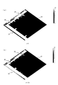
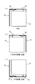
- FIG. 1 is a perspective view showing a configuration of an embodiment of a circularly polarized antenna.
- the circularly polarized antenna 1 includes a ground conductor plate 10, an inverted F antenna 20 ( ⁇ / 4 type antenna), a dipole antenna 30 ( ⁇ / 2 type antenna), and a feeding unit 40.
- the inverted F antenna 20 functions as a first linear antenna
- the dipole antenna 30 functions as a second linear antenna.
- the ground conductor plate 10 is formed of a rectangular sheet metal.
- the size of the ground conductor plate 10 is 40 mm ⁇ 40 mm.
- the inverted F antenna 20 includes an antenna main portion 21 disposed substantially parallel to the side 11 of the ground conductor plate 10, and a first short-circuit portion 22 that connects the end portion side of the antenna main portion 21 and the ground conductor plate 10. And the second short-circuit portion 23 are provided.
- the first short-circuit portion 22 connects the end portion of the antenna main portion 21 and the end portion of the ground conductor plate 10, and the second short-circuit portion 23 is substantially parallel to the antenna main portion on the open end side with respect to the first short-circuit portion 22.
- the part 21 and the ground conductor plate 10 are connected.
- the inverted F antenna 20 is formed with a line width of 1 mm as a whole, the length of the antenna main portion 21 is 32 mm, and the length of the first short-circuit portion 22 and the second short-circuit portion 23 is 4 mm (in the drawing, the antenna main portion 21 The width is added and displayed as 5 mm). With respect to the first short-circuit portion 22, the second short-circuit portion 23 is disposed with an interval of 9 mm.
- the inverted F antenna 20 of the present embodiment is integrally formed of the same material as the ground conductor plate 10, but may be formed separately and connected to each other, or may be formed of a different material. .
- the dipole antenna 30 is provided with an antenna main portion 31 disposed substantially in parallel with the other side 12 orthogonal to the side 11 of the ground conductor plate 10, and extends from the antenna main portion 31 toward the side 11.
- a bent portion 32 is provided.
- the bent portion 32 functions as an open end side facing a power supply portion 40 described later.
- the dipole antenna 30 is formed as a whole with a line width of 1 mm, the antenna main part 31 is 45 mm long, and the bent part 32 is 7 mm long.
- the distance between the antenna main portion 31 and the side 12 of the ground conductor plate 10 is 5 mm.
- the open end of the bent portion 32 and the open end of the antenna main portion 21 in the inverted F antenna 20 are arranged at a predetermined interval so that they do not come into contact with each other.
- an interval of 7 mm (not shown) ) Is opened.
- the bent portion 32 is bent so as to face the power feeding portion 40, but is not necessary when the power feeding portion 40 side is bent as will be described later, and the antenna main portion 31 is formed longer by that amount. (See FIG. 9A).
- the power feeding unit 40 is disposed in parallel with the side 11 of the ground conductor plate 10 so as to be opposed to the open end side of the inverted F antenna 20 and the open end side (bent portion 32) of the dipole antenna 30 with a predetermined distance therebetween. 41 and a power supply line 42 electrically connected to the EM power supply unit 41 at one end side. The other end side of the feed line 42 extends to the ground conductor plate 10 side, and has a feed point P1 at the end thereof.
- the power feeding unit 40 is formed to have a line width of 1 mm throughout, and the length of the EM power feeding unit 41 is formed to 17 mm (not shown), and a power feeding region of about 5 mm (not shown) on both ends or the vicinity thereof. The feed region having the value of 1 is opposed to the open end side of the inverted F antenna 20 and the dipole antenna 30 with an interval of 0.5 mm.
- a general inverted-F antenna has a short-circuited portion near the outside of the feeding point in order to facilitate impedance matching of an inverted-L antenna that is bent in the middle to lower the profile.
- the feeding point is not connected to the ground conductor plate.
- electromagnetic coupling EM coupling
- the power feeding unit 40 disposed opposite to the open end side of the antenna main part 21 and the second short circuit corresponding to the power feeding point.
- the part 23 is connected to the ground conductor plate 10.
- the EM power feeding portion 41 when the EM power feeding portion 41 is electromagnetically fed (EM feeding) to the inverted F antenna 20, a current also flows to the second short-circuit portion 23 via the antenna main portion 21, thereby causing the second short-circuit.
- the part 23 acts in the same manner as a general feeding point and functions as a general inverted F antenna as a whole. The same applies to the inverted L antenna used in FIG. 8 and FIG.
- an inverted F-type antenna 20 ( ⁇ / 4 type) and a dipole antenna 30 ( ⁇ / 2 type) are arranged orthogonally on a sheet metal and fed at one point by EM coupling. It was possible to generate an antenna, and it was possible to generate circularly polarized waves that ensure high gain (about 3 dBc), high efficiency (a little less than 90%), and good angular width.
- FIG. 2 is an explanatory diagram showing the return loss characteristics of the circularly polarized antenna 1.
- the length directions of the side 11 and the side 12 of the ground conductor plate 10 are the Y axis and the X axis, respectively.
- the direction orthogonal to 10 will be described as the Z-axis direction.
- the phase difference of ⁇ / 2 is substantially obtained at f0 due to the difference ⁇ between the resonant frequencies of the inverted F antenna 20 and the dipole antenna 30. One is satisfied.
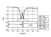
- FIG. 3 is an explanatory diagram showing the axial ratio (AR) characteristic and directivity characteristic of the circularly polarized antenna 1.
- the frequency of 3 dB or less which is an indication of good circular polarization, is 136.9 degrees to 205.6 degrees.
- BW 68.8 degrees
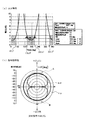
- 4 and 5 are explanatory diagrams showing the distribution state of the surface current density (2.44 GHz) of the circularly polarized antenna 1.
- T represents a period.
- the black and white state is almost black due to the image accuracy of the drawings, but the surface current density is higher as it approaches white. As shown in FIG.
- the high-frequency current only rides on the edge (near the outer periphery) of the ground conductor plate 10. That is, according to the circularly polarized antenna 1 of the present embodiment, the high frequency current does not get on the central portion of the ground conductor plate 10. Therefore, when the length of one side of the ground conductor plate 10 is L, it is possible to cut out the central L / 2 or 3L / 5 square range, or the range of the vicinity thereof. Thereby, the weight of the circularly polarized antenna 1 can be reduced. Further, since the high frequency current is not applied to the central region of the ground conductor plate 10, an electronic circuit or the like can be disposed in the region. It is also possible to cut out the central region as described above and arrange an electronic circuit or the like in the cutout region.
- the circularly polarized wave antenna 1 of the present embodiment it is formed so as to face each of the two orthogonal sides 11 and 12 of the ground conductor plate 10 and have a phase difference of approximately ⁇ / 2.
- the inverted F antenna 20 and the dipole antenna 30 are disposed so as to be substantially orthogonal.
- the EM power feeding portion 41 of the common power feeding portion 40 is disposed opposite to the open end side of the inverted F antenna 20 and the open end side of the dipole antenna 30, so that electromagnetic power feeding to both antennas 20 and 30 is performed. Is performed at one point.
- the circularly polarized antenna 1 of the present embodiment can be easily manufactured by adopting the one-point power feeding method based on the EM power feeding. Further, by using the inverted F antenna 20 and the dipole antenna 30 as the first and second linear antennas, the size can be reduced as compared with a circularly polarized antenna using a conventional patch antenna.
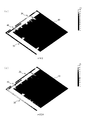
- FIG. 6 is an explanatory diagram showing the arrangement of the circularly polarized antenna 1 and the switching of the polarization. Except for FIG. 10A, in the drawings of FIG. 6 and the subsequent drawings, the shape and arrangement state of each antenna are described, and therefore simplified.
- FIG. 6A shows the reference circularly polarized antenna 1 which is the same as the circularly polarized antenna 1 described in FIG. With respect to this reference, as shown in FIGS. 6B and 6C, the turning direction of the circularly polarized wave can be reversed by reversing the front and back of the circularly polarized antenna 1 arranged as a reference. it can.
- FIG. 6B shows a case where they are arranged symmetrically (inverted with respect to the longitudinal center axis), and FIG.
- FIG. 6C shows a case where they are arranged symmetrically vertically (inverted with respect to the lateral center axis). is there.
- the turning direction of the circularly polarized wave (right / left) can be easily changed.
- FIG. 7 shows a configuration of a modified example of the circularly polarized antenna 1.
- FIG. 7A shows two sets of circularly polarized antennas 1 described in FIG. 1 arranged in point symmetry (on the opposite side). That is, with respect to one ground conductor plate 10, a second circular polarization antenna 1a including an inverted F antenna 20a, a dipole antenna 30a, and a power feeding unit 40a, a second antenna including an inverted F antenna 20b, a dipole antenna 30b, and a power feeding unit 40b.
- Two sets of circularly polarized antennas 1b are arranged point-symmetrically.
- the resonance frequency (for example, 2.44 GHz) of both circularly polarized antennas 1a and 1b is supplied in common and in phase, thereby gain compared to the circularly polarized antenna 1 described in the embodiment. Can be improved.
- a dual-polarized circularly polarized antenna can be provided.
- the first circularly polarized antenna 1a is set to the 2.44 GHz band
- the second circularly polarized antenna 1b is set to the 5.2 GHz band.
- FIG. 8 shows modified examples in which other types of antennas are combined.
- any one of an inverted F antenna, an inverted L antenna, and a dipole antenna can be selected, and the selectable combinations are shown in FIG.
- the inverted F antenna and the inverted L antenna are simply expressed as inverted F and inverted L
- the dipole antenna is simply expressed as a dipole.
- both ⁇ / 4 type antennas are arranged as the first linear antenna and the second linear antenna.
- FIG. 8A shows an inverted F + inverted F-type circularly polarized antenna in which two inverted F antennas are arranged so that the open end side is on the same corner side of the ground conductor plate 10.
- the open end side is bent so as to face the EM power feeding portion 41, similarly to the bent portion 32 of the dipole antenna 30 described in FIG. The same applies to the bending of the open end side of one of the antennas so as to oppose the EM feeding portion 41 in FIGS. 8B to 8E.
- FIG. 8B is an example of an inverted F + inverted L type circularly polarized antenna in which an inverted L antenna is arranged instead of the dipole antenna 30 of the embodiment. Also in this example, the feeding portion 40 side is bent with the open end side, and a short-circuit portion is provided on the opposite side.
- FIG. 8C shows an inverted L + inverted L type circularly polarized antenna in which both the inverted F antenna 20 and the dipole antenna 30 of the embodiment are replaced with an inverted L antenna. 8A to 8C, the short-circuit portions of both antennas are arranged so as to be diagonally located with respect to the ground conductor plate 10.
- FIG. 8D is an example of an inverted L + dipole circularly polarized antenna in which an inverted L antenna is arranged instead of the inverted F antenna 20 of the embodiment.
- ⁇ / 4 type and ⁇ / 2 type antennas are used as in the embodiment.
- the circularly polarized antennas according to the modified examples described in FIGS. 8A to 8D all use ⁇ / 4 type antennas (inverted F antenna and inverted L antenna).
- the conductor plate 10 is required. Further, as described with reference to FIGS. 4 and 5 for the circularly polarized antenna 1 of the embodiment, a high-frequency current is also applied to the central portion of the ground conductor plate 10 in each of the modified examples of FIGS. never ride. Therefore, also in these modified examples, the central portion of the ground conductor plate 10 can be cut out or an electronic circuit can be provided.
- FIG. 8E shows an example of a dipole + dipole circularly polarized antenna in which a dipole antenna is arranged instead of the inverted F antenna 20 of the embodiment. According to this modification, since both are ⁇ / 2 type antennas, the ground conductor plate 10 is not required, and a light-weight circularly polarized antenna can be obtained.
- each of the first circularly polarized antenna 1a and the second circularly polarized antenna 1b is an arbitrary one of FIGS. 8 (a) to 8 (e). It is also possible to select one.
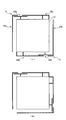
- FIG. 9 is an explanatory diagram of a modified example in which the shape of the feeding portion is changed in the circularly polarized antenna 1.
- the antenna main portion 21 of the inverted F antenna 20 and the bent portion 32 of the dipole antenna 30 are arranged on substantially the same straight line, so that a linear shape is obtained.
- the case where the EM power feeding portion 41 is disposed opposite to the open ends of both antennas has been described.
- FIG. 9 (a) the open end side of the dipole antenna 30c (second linear antenna) is not bent, and only the linear antenna main part 31c is configured, and the EM power feeding part 41c is bent instead.
- the dipole antenna 30c is disposed opposite to the open end.
- the antenna main portion 21 of the inverted F antenna 20 and the bent portion 32 of the dipole antenna 30d are not arranged on the same line but arranged in parallel with a predetermined interval,
- the EM power feeding part 41d is arranged inside. Accordingly, in the example of FIG. 9, when the side facing the ground conductor plate 10 of the EM power feeding portion 41 is the inner side and the opposite side is the outer side, the antenna main portion 21 of the inverted F antenna 20 is outside the EM feeding portion 41 d.
- the bent portion of the dipole antenna 30d faces the inside of the EM power feeding portion 41d.
- FIG. 9 (a), (b) about the shape of the open end side of both antennas (a 1st linear antenna and a 2nd linear antenna) shown in FIG. 9 (a), (b), and the shape and arrangement
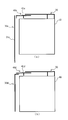
- FIG. 10 is an explanatory diagram showing the configuration of another modification of the circularly polarized antenna 1.
- FIG. 10A shows a modification of the circularly polarized antenna in which the inverted F antenna 20, the dipole antenna 30, and the power feeding unit 40 are three-dimensionally structured. As shown in FIG. 10A, the first short-circuit portion 22e and the second short-circuit portion 23e of the inverted F antenna 20e connected to the ground conductor plate 10 are bent at a right angle with respect to the ground conductor plate 10, so that Z It is formed on the -Y plane.
- the dipole antenna 30e As for the dipole antenna 30e, as described above, the central portion in the length direction where the voltage is zero is connected by the short-circuit portion 33e, and the short-circuit portion 33e is bent at a right angle with respect to the ground conductor plate 10, thereby It is formed on a plane.
- the feed line 42e Corresponding to the fact that the inverted F antenna 20e and the dipole antenna 30e are bent in a right angle direction, the feed line 42e has a three-dimensional structure so as to be orthogonal to the ground conductor plate 10 in the same manner. It is formed on the -Y plane.
- the bent portion 32e of the dipole antenna 30e has a shorter length than the embodiment described with reference to FIG. 1 due to the three-dimensional structure.
- the end portion 43e on the dipole antenna 30e side of the EM feed portion 41e is not 12 (see FIG. 1). According to the modification shown in FIG. 10A, the arrangement area of the entire circularly polarized antenna can be reduced.
- an inverted L antenna 50 and a dipole are provided as a second circularly polarized antenna further outside the inverted F antenna 20 and the dipole antenna 30 of the circularly polarized antenna described in FIG.
- An antenna 60 is provided.
- the inverted L antenna 50 forms a short-circuit portion (a feeding line portion in a general inverted-L antenna) on an extension line of the second short-circuit portion 23 of the inverted F antenna 20.
- the electric power feeding part 40 it is made to electromagnetically feed in common with two sets of circularly polarized antennas.
- a multi-frequency circularly polarized antenna can be provided.
- each circularly polarized antenna described may be formed on a substrate having a high relative dielectric constant such as glass epoxy resin. This makes it possible to provide a circularly polarized antenna that is miniaturized at the same wavelength (same resonance frequency) by utilizing the fact that the wavelength is shortened when the same size is used as a reference.
- the single-layer circularly polarized antenna has been described.
- each circular polarization of the embodiment and the modification described above on the high relative dielectric constant substrate such as a glass epoxy resin is used.
- the antenna layer may be multilayered (for example, two layers, four layers, eight layers).
- the respective portions of the ground conductor plate 10, the inverted F antenna 20, the dipole antenna 30, and the power feeding unit 40 in the polarization sharing antenna of each layer are connected to each other via.
- the power supply line 42 of the power supply unit 40 may have a single layer and may be connected to the EM power supply unit 41 of any one layer.
- the antenna has n layers, and the high-permittivity substrate has n ⁇ 1 layers. You may arrange
- the antenna element shape in a straight state is described except for the open end.
- the shape is not limited to the linear shape.
- a meander shape, a helical shape, or a bent end shape (a bent end shape) can be used.
Abstract
L'invention concerne une antenne à polarisation circulaire de taille réduite qui peut être fabriquée plus facilement. Dans une antenne à polarisation circulaire (1) selon un mode de réalisation de la présente invention, une antenne en F inversé (20) ayant une extrémité ouverte au niveau d'un côté de coin est disposée sur un côté de deux côtés orthogonaux d'une plaque conductrice de mise à la terre (10) rectangulaire et une antenne dipôle (30) est disposée sur l'autre côté. Une unité d'alimentation en énergie EM (41) d'une unité d'alimentation en énergie (40) est placée de façon à faire face à chacun des côtés de l'extrémité ouverte des deux antennes. Un côté de l'antenne en F inversé (20), opposé à l'extrémité ouverte, est connecté à la plaque conductrice de mise à la terre (10) de manière à être court-circuité par une première partie de court-circuit (22) et par une seconde partie de court-circuit (23). Ainsi, l'antenne en F inversé (20) (de type λ/4) et l'antenne dipôle (30) (de type λ/2) sont disposées orthogonalement sur une feuille métallique, et une alimentation électrique en un point est réalisée par couplage EM. En conséquence, une antenne à polarisation circulaire qui peut être facilement fabriquée peut être fournie et, en outre, une onde polarisée circulaire permettant d'assurer un gain élevé (environ 3 dBc), un rendement élevé (légèrement inférieur à 90 %) et une bonne largeur d'angle peut être générée.
Applications Claiming Priority (2)
| Application Number | Priority Date | Filing Date | Title |
|---|---|---|---|
| JP2017-064781 | 2017-03-29 | ||
| JP2017064781A JP6678617B2 (ja) | 2017-03-29 | 2017-03-29 | 円偏波アンテナ |
Publications (1)
| Publication Number | Publication Date |
|---|---|
| WO2018180875A1 true WO2018180875A1 (fr) | 2018-10-04 |
Family
ID=63675677
Family Applications (1)
| Application Number | Title | Priority Date | Filing Date |
|---|---|---|---|
| PCT/JP2018/011372 WO2018180875A1 (fr) | 2017-03-29 | 2018-03-22 | Antenne à polarisation circulaire |
Country Status (2)
| Country | Link |
|---|---|
| JP (1) | JP6678617B2 (fr) |
| WO (1) | WO2018180875A1 (fr) |
Cited By (5)
| Publication number | Priority date | Publication date | Assignee | Title |
|---|---|---|---|---|
| CN109546320A (zh) * | 2018-11-15 | 2019-03-29 | 南京尤圣美电子科技有限公司 | 一种手持终端全向圆极化天线 |
| DE202019100718U1 (de) | 2019-02-08 | 2020-05-11 | Sick Ag | Antenne für einen RFID-Leser |
| EP3694048A1 (fr) | 2019-02-08 | 2020-08-12 | Sick Ag | Antenne pour un lecteur rfid et procédé d'identification d'un rôle |
| CN113745849A (zh) * | 2020-05-28 | 2021-12-03 | 广东小天才科技有限公司 | 单频圆极化定位天线和可穿戴设备 |
| US11967779B2 (en) | 2020-05-28 | 2024-04-23 | Guangdong Genius Technology Co., Ltd. | Single-frequency circular polarization positioning antenna and wearable device |
Citations (7)
| Publication number | Priority date | Publication date | Assignee | Title |
|---|---|---|---|---|
| JPH0955621A (ja) * | 1995-08-14 | 1997-02-25 | Toyo Commun Equip Co Ltd | アレーアンテナ |
| JPH11239020A (ja) * | 1997-04-18 | 1999-08-31 | Murata Mfg Co Ltd | 円偏波アンテナおよびそれを用いた無線装置 |
| JP2001119232A (ja) * | 1999-10-21 | 2001-04-27 | Yokowo Co Ltd | 円偏波用平面アンテナ |
| JP2005236656A (ja) * | 2004-02-19 | 2005-09-02 | Fujitsu Ten Ltd | 円偏波用アンテナ |
| WO2007083574A1 (fr) * | 2006-01-19 | 2007-07-26 | Murata Manufacturing Co., Ltd. | Dispositif de circuit intégré radio et partie de dispositif de circuit intégré radio |
| JP2008278219A (ja) * | 2007-04-27 | 2008-11-13 | Toshiba Corp | アンテナ装置 |
| US20090231229A1 (en) * | 2007-05-16 | 2009-09-17 | Motorola, Inc. | Circular polarized antenna |
Family Cites Families (3)
| Publication number | Priority date | Publication date | Assignee | Title |
|---|---|---|---|---|
| JP2007159064A (ja) * | 2005-12-08 | 2007-06-21 | Sony Corp | アンテナとそれを用いた無線装置および電子機器 |
| JP2009076960A (ja) * | 2007-09-18 | 2009-04-09 | Samsung Electronics Co Ltd | アンテナ装置 |
| JP2011082951A (ja) * | 2009-09-14 | 2011-04-21 | Nagasaki Univ | 逆l型アンテナ |
-
2017
- 2017-03-29 JP JP2017064781A patent/JP6678617B2/ja active Active
-
2018
- 2018-03-22 WO PCT/JP2018/011372 patent/WO2018180875A1/fr active Application Filing
Patent Citations (7)
| Publication number | Priority date | Publication date | Assignee | Title |
|---|---|---|---|---|
| JPH0955621A (ja) * | 1995-08-14 | 1997-02-25 | Toyo Commun Equip Co Ltd | アレーアンテナ |
| JPH11239020A (ja) * | 1997-04-18 | 1999-08-31 | Murata Mfg Co Ltd | 円偏波アンテナおよびそれを用いた無線装置 |
| JP2001119232A (ja) * | 1999-10-21 | 2001-04-27 | Yokowo Co Ltd | 円偏波用平面アンテナ |
| JP2005236656A (ja) * | 2004-02-19 | 2005-09-02 | Fujitsu Ten Ltd | 円偏波用アンテナ |
| WO2007083574A1 (fr) * | 2006-01-19 | 2007-07-26 | Murata Manufacturing Co., Ltd. | Dispositif de circuit intégré radio et partie de dispositif de circuit intégré radio |
| JP2008278219A (ja) * | 2007-04-27 | 2008-11-13 | Toshiba Corp | アンテナ装置 |
| US20090231229A1 (en) * | 2007-05-16 | 2009-09-17 | Motorola, Inc. | Circular polarized antenna |
Cited By (8)
| Publication number | Priority date | Publication date | Assignee | Title |
|---|---|---|---|---|
| CN109546320A (zh) * | 2018-11-15 | 2019-03-29 | 南京尤圣美电子科技有限公司 | 一种手持终端全向圆极化天线 |
| DE202019100718U1 (de) | 2019-02-08 | 2020-05-11 | Sick Ag | Antenne für einen RFID-Leser |
| EP3694048A1 (fr) | 2019-02-08 | 2020-08-12 | Sick Ag | Antenne pour un lecteur rfid et procédé d'identification d'un rôle |
| US10950923B2 (en) | 2019-02-08 | 2021-03-16 | Sick Ag | Antenna for an RFID reader and method for identifying a roll |
| DE102019103102B4 (de) | 2019-02-08 | 2021-09-30 | Sick Ag | Antenne für einen RFID-Leser und Verfahren zum Identifizieren einer Rolle |
| CN113745849A (zh) * | 2020-05-28 | 2021-12-03 | 广东小天才科技有限公司 | 单频圆极化定位天线和可穿戴设备 |
| CN113745849B (zh) * | 2020-05-28 | 2023-12-26 | 广东小天才科技有限公司 | 单频圆极化定位天线和可穿戴设备 |
| US11967779B2 (en) | 2020-05-28 | 2024-04-23 | Guangdong Genius Technology Co., Ltd. | Single-frequency circular polarization positioning antenna and wearable device |
Also Published As
| Publication number | Publication date |
|---|---|
| JP2018170561A (ja) | 2018-11-01 |
| JP6678617B2 (ja) | 2020-04-08 |
Similar Documents
| Publication | Publication Date | Title |
|---|---|---|
| WO2018180875A1 (fr) | Antenne à polarisation circulaire | |
| Guo et al. | Advances in reconfigurable antenna systems facilitated by innovative technologies | |
| Orban et al. | The basics of patch antennas, updated | |
| Chen et al. | Single-fed microstrip patch antenna with switchable polarization | |
| US8223084B2 (en) | Antenna element | |
| Liao et al. | Polarization reconfigurable eccentric annular ring slot antenna design | |
| AU2006222394B2 (en) | Aperture-coupled antenna | |
| Ko et al. | Hybrid zeroth-order resonance patch antenna with broad $ E $-Plane beamwidth | |
| Jin et al. | High-directivity, electrically small, low-profile near-field resonant parasitic antennas | |
| US20090140943A1 (en) | Slot antenna for mm-wave signals | |
| US10756420B2 (en) | Multi-band antenna and radio communication device | |
| WO2001048866A1 (fr) | Antenne a deux frequences, antenne a plusieurs frequences, reseau d'antennes a deux ou plusieurs frequences | |
| Chang et al. | A symmetrical reconfigurable multipolarization circular patch antenna | |
| Zhang et al. | 45 GHz wideband circularly polarized planar antenna array using inclined slots in modified short-circuited SIW | |
| KR20110025047A (ko) | 향상된 대역폭 및 높은 효율을 가지며 구현이 간단한 소형 0차 공진 안테나 | |
| JP4128934B2 (ja) | 多周波共用アンテナ | |
| JP6456506B2 (ja) | アンテナ装置 | |
| Ooi et al. | 2.45 GHz and 5.8 GHz compact dual-band circularly polarized patch antenna | |
| JP6145785B1 (ja) | アンテナ装置 | |
| WO2018180877A1 (fr) | Antenne d'émission/de réception d'ondes à double polarisation | |
| Tawk et al. | A polarization reconfigurable 3D printed dual integrated quadrifilar helix antenna array embedded within a cylindrical dielectric mesh | |
| JPWO2009019740A1 (ja) | 可変指向性アンテナ | |
| JP2002094323A (ja) | 円偏波アンテナ装置 | |
| WO2018180876A1 (fr) | Antenne à polarisation circulaire | |
| Nguyen | A new metasurface structure for bandwidth improvement of antenna array |
Legal Events
| Date | Code | Title | Description |
|---|---|---|---|
| 121 | Ep: the epo has been informed by wipo that ep was designated in this application |
Ref document number: 18777574 Country of ref document: EP Kind code of ref document: A1 |
|
| NENP | Non-entry into the national phase |
Ref country code: DE |
|
| 122 | Ep: pct application non-entry in european phase |
Ref document number: 18777574 Country of ref document: EP Kind code of ref document: A1 |