WO2018180160A1 - 車両誘導装置、方法及びプログラム - Google Patents
車両誘導装置、方法及びプログラム Download PDFInfo
- Publication number
- WO2018180160A1 WO2018180160A1 PCT/JP2018/007641 JP2018007641W WO2018180160A1 WO 2018180160 A1 WO2018180160 A1 WO 2018180160A1 JP 2018007641 W JP2018007641 W JP 2018007641W WO 2018180160 A1 WO2018180160 A1 WO 2018180160A1
- Authority
- WO
- WIPO (PCT)
- Prior art keywords
- vehicle
- information
- route guidance
- unit
- route
- Prior art date
- Legal status (The legal status is an assumption and is not a legal conclusion. Google has not performed a legal analysis and makes no representation as to the accuracy of the status listed.)
- Ceased
Links
Images





Classifications
-
- B—PERFORMING OPERATIONS; TRANSPORTING
- B62—LAND VEHICLES FOR TRAVELLING OTHERWISE THAN ON RAILS
- B62D—MOTOR VEHICLES; TRAILERS
- B62D15/00—Steering not otherwise provided for
- B62D15/02—Steering position indicators ; Steering position determination; Steering aids
- B62D15/027—Parking aids, e.g. instruction means
- B62D15/0285—Parking performed automatically
-
- B—PERFORMING OPERATIONS; TRANSPORTING
- B60—VEHICLES IN GENERAL
- B60R—VEHICLES, VEHICLE FITTINGS, OR VEHICLE PARTS, NOT OTHERWISE PROVIDED FOR
- B60R99/00—Subject matter not provided for in other groups of this subclass
-
- B—PERFORMING OPERATIONS; TRANSPORTING
- B62—LAND VEHICLES FOR TRAVELLING OTHERWISE THAN ON RAILS
- B62D—MOTOR VEHICLES; TRAILERS
- B62D15/00—Steering not otherwise provided for
- B62D15/02—Steering position indicators ; Steering position determination; Steering aids
- B62D15/027—Parking aids, e.g. instruction means
- B62D15/028—Guided parking by providing commands to the driver, e.g. acoustically or optically
-
- G—PHYSICS
- G01—MEASURING; TESTING
- G01S—RADIO DIRECTION-FINDING; RADIO NAVIGATION; DETERMINING DISTANCE OR VELOCITY BY USE OF RADIO WAVES; LOCATING OR PRESENCE-DETECTING BY USE OF THE REFLECTION OR RERADIATION OF RADIO WAVES; ANALOGOUS ARRANGEMENTS USING OTHER WAVES
- G01S15/00—Systems using the reflection or reradiation of acoustic waves, e.g. sonar systems
- G01S15/02—Systems using the reflection or reradiation of acoustic waves, e.g. sonar systems using reflection of acoustic waves
- G01S15/06—Systems determining the position data of a target
- G01S15/08—Systems for measuring distance only
-
- G—PHYSICS
- G01—MEASURING; TESTING
- G01S—RADIO DIRECTION-FINDING; RADIO NAVIGATION; DETERMINING DISTANCE OR VELOCITY BY USE OF RADIO WAVES; LOCATING OR PRESENCE-DETECTING BY USE OF THE REFLECTION OR RERADIATION OF RADIO WAVES; ANALOGOUS ARRANGEMENTS USING OTHER WAVES
- G01S15/00—Systems using the reflection or reradiation of acoustic waves, e.g. sonar systems
- G01S15/88—Sonar systems specially adapted for specific applications
- G01S15/93—Sonar systems specially adapted for specific applications for anti-collision purposes
- G01S15/931—Sonar systems specially adapted for specific applications for anti-collision purposes of land vehicles
-
- G—PHYSICS
- G01—MEASURING; TESTING
- G01S—RADIO DIRECTION-FINDING; RADIO NAVIGATION; DETERMINING DISTANCE OR VELOCITY BY USE OF RADIO WAVES; LOCATING OR PRESENCE-DETECTING BY USE OF THE REFLECTION OR RERADIATION OF RADIO WAVES; ANALOGOUS ARRANGEMENTS USING OTHER WAVES
- G01S7/00—Details of systems according to groups G01S13/00, G01S15/00, G01S17/00
- G01S7/52—Details of systems according to groups G01S13/00, G01S15/00, G01S17/00 of systems according to group G01S15/00
- G01S7/521—Constructional features
-
- G—PHYSICS
- G05—CONTROLLING; REGULATING
- G05D—SYSTEMS FOR CONTROLLING OR REGULATING NON-ELECTRIC VARIABLES
- G05D1/00—Control of position, course, altitude or attitude of land, water, air or space vehicles, e.g. using automatic pilots
- G05D1/02—Control of position or course in two dimensions
- G05D1/021—Control of position or course in two dimensions specially adapted to land vehicles
- G05D1/0212—Control of position or course in two dimensions specially adapted to land vehicles with means for defining a desired trajectory
-
- G—PHYSICS
- G05—CONTROLLING; REGULATING
- G05D—SYSTEMS FOR CONTROLLING OR REGULATING NON-ELECTRIC VARIABLES
- G05D1/00—Control of position, course, altitude or attitude of land, water, air or space vehicles, e.g. using automatic pilots
- G05D1/02—Control of position or course in two dimensions
- G05D1/021—Control of position or course in two dimensions specially adapted to land vehicles
- G05D1/0255—Control of position or course in two dimensions specially adapted to land vehicles using acoustic signals, e.g. ultra-sonic singals
-
- G—PHYSICS
- G08—SIGNALLING
- G08G—TRAFFIC CONTROL SYSTEMS
- G08G1/00—Traffic control systems for road vehicles
- G08G1/14—Traffic control systems for road vehicles indicating individual free spaces in parking areas
-
- G—PHYSICS
- G01—MEASURING; TESTING
- G01S—RADIO DIRECTION-FINDING; RADIO NAVIGATION; DETERMINING DISTANCE OR VELOCITY BY USE OF RADIO WAVES; LOCATING OR PRESENCE-DETECTING BY USE OF THE REFLECTION OR RERADIATION OF RADIO WAVES; ANALOGOUS ARRANGEMENTS USING OTHER WAVES
- G01S15/00—Systems using the reflection or reradiation of acoustic waves, e.g. sonar systems
- G01S15/86—Combinations of sonar systems with lidar systems; Combinations of sonar systems with systems not using wave reflection
-
- G—PHYSICS
- G01—MEASURING; TESTING
- G01S—RADIO DIRECTION-FINDING; RADIO NAVIGATION; DETERMINING DISTANCE OR VELOCITY BY USE OF RADIO WAVES; LOCATING OR PRESENCE-DETECTING BY USE OF THE REFLECTION OR RERADIATION OF RADIO WAVES; ANALOGOUS ARRANGEMENTS USING OTHER WAVES
- G01S15/00—Systems using the reflection or reradiation of acoustic waves, e.g. sonar systems
- G01S15/88—Sonar systems specially adapted for specific applications
- G01S15/93—Sonar systems specially adapted for specific applications for anti-collision purposes
- G01S15/931—Sonar systems specially adapted for specific applications for anti-collision purposes of land vehicles
- G01S2015/932—Sonar systems specially adapted for specific applications for anti-collision purposes of land vehicles for parking operations
Definitions
- Embodiments described herein relate generally to a vehicle guidance device, a method, and a program.
- a technique for detecting obstacles around the vehicle by a plurality of ultrasonic sensor devices (sonars) installed in the vehicle and notifying the driver of the presence of the obstacle, an imaging device A technique has been proposed in which an obstacle around the vehicle is detected based on image data captured by the camera) as the surrounding environment of the vehicle and the presence of the obstacle is notified to the driver.
- a vehicle guidance device is a vehicle guidance device that is mounted on a vehicle and performs route guidance of the vehicle, and for ultrasonic distance measurement that measures a distance to a measurement object.
- a plurality of receiving units that receive a ranging information signal in which the route guidance information is superimposed on the signal via a ranging ultrasonic sensor, and information for extracting the routing guidance information from the ranging information signal for each of the receiving units An extraction unit; and a route guidance unit that performs the route guidance based on the distance corresponding to the ultrasonic ranging signal and the route guidance information.
- the route guidance information is received and extracted via the ranging ultrasonic sensor used for obstacle detection or the like, and the route is based on the distance and the route guidance information corresponding to the ultrasonic ranging signal. Since guidance is performed, it is possible to reliably collect information and guide the vehicle.
- the route guidance information includes identification information for specifying a transmitter that has transmitted the ranging information signal
- the route guidance unit includes the identification information and the plurality of information.
- the route guidance may be performed by calculating the position and direction of the vehicle based on the arrangement information of the receiving unit. According to the said structure, the position and direction of a vehicle can be calculated reliably and a more detailed and exact route guidance can be performed.
- the route guidance unit acquires and stores in advance the arrangement information of the transmitter corresponding to the identification information, and performs the route guidance based on the arrangement information of the transmitter. You may make it perform. According to the above configuration, even in a situation where route guidance is performed for the first time, it is possible to grasp the entire route and reliably perform route guidance.
- the transmitter arrangement information is obtained as the distance measurement information signal from the transmitter arranged in the area when the vehicle enters the area where the route guidance is performed. You may make it receive. According to the above configuration, even in an area (region, facility, etc.) where a route is visited for the first time, the entire route can be grasped and route guidance can be reliably performed.
- the route guidance information includes planned travel route information of the vehicle, and the route guidance unit provides the driver with the planned travel route based on the planned travel route information. You may make it provide the information presentation part which presents the information for guide
- the route guidance unit calculates an error between the planned travel route and the actual travel route of the vehicle, and an error between the guidance route and the actual travel route is predetermined. You may make it provide the steering control part which controls the steering angle of the wheel of the said vehicle so that the said error may become less than predetermined value when it becomes more than a value.
- the vehicle can be driven to a desired guidance location by operating the vehicle by the steering control unit based on the information for guiding the vehicle.
- the route guidance unit calculates an error between the planned travel route and the actual travel route of the vehicle, and an error between the guidance route and the actual travel route is predetermined.
- a steering information presenting unit that guides the steering information of the vehicle may be provided so that the error is less than a predetermined value when the value is greater than or equal to the value. According to the above configuration, it is possible to travel to a desired guidance location along the guidance route only by performing an operation according to the steering information of the vehicle guided by the steering information presentation unit.
- the route guidance information includes information for guiding to a parking space and information about a parking completion position, and the vehicle has an automatic parking driving mode in which automatic parking is performed as a driving mode.
- the route guidance unit when detecting that the vehicle has reached the vicinity of the parking space, shifts to the automatic parking operation mode and reaches the parking completion position based on the route guidance information. You may make it control so that it may. According to the above configuration, the vehicle can shift to the automatic parking operation mode and reach the parking completion position based on the route guidance information.
- a method is a method that is executed by a vehicle guidance device that is mounted on a vehicle and performs route guidance of the vehicle, and is routed to an ultrasonic distance measurement signal that measures a distance to a measurement object.
- a process of receiving a ranging information signal on which information is superimposed via a plurality of receiving units via a ranging ultrasonic sensor, and a process of extracting the route guidance information from the ranging information signal for each receiving unit And a step of performing the route guidance based on the distance corresponding to the ultrasonic ranging signal and the route guidance information.
- the route guidance information is received and extracted via the ranging ultrasonic sensor used for obstacle detection or the like, and the route is based on the distance and the route guidance information corresponding to the ultrasonic ranging signal. Since guidance is performed, it is possible to reliably collect information and guide the vehicle.
- the program of the embodiment is mounted on a vehicle, and a distance measurement information signal obtained by superimposing route guidance information on an ultrasonic distance measurement signal for measuring a distance to a measurement object is transmitted via a distance measurement ultrasonic sensor.
- the route guidance information is received and extracted via the ranging ultrasonic sensor used for obstacle detection or the like, and the route is based on the distance and the route guidance information corresponding to the ultrasonic ranging signal. Since guidance is performed, it is possible to reliably collect information and guide the vehicle.
- FIG. 1 is an exemplary perspective view illustrating a state in which a part of a passenger compartment of a vehicle according to an embodiment is seen through.
- FIG. 2 is an exemplary plan view (overhead view) of the vehicle according to the embodiment.
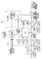
- FIG. 3 is an exemplary block diagram of a configuration of the parking assistance system according to the embodiment.
- FIG. 4 is a schematic configuration block diagram of the ranging communication unit.
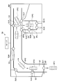
- FIG. 5 is an explanatory diagram of a schematic configuration of the parking lot system.
- FIG. 6 is an explanatory diagram of an example of a data format of communication data.
- FIG. 7 is a process flowchart of the ECU when data is received from an external sensor unit that functions as a gate sensor.
- FIG. 1 is an exemplary perspective view illustrating a state in which a part of a passenger compartment of a vehicle according to an embodiment is seen through.
- FIG. 2 is an exemplary plan view (overhead view) of the vehicle according to the embodiment.
- FIG. 3 is an exemplary block
- FIG. 8 is a process flowchart of the ECU when data is received from an external sensor unit that functions as a travel path sensor.
- FIG. 9 is a process flowchart of the ECU when data is received from an external sensor unit that functions as a curve sensor.
- FIG. 10 is a process flowchart of the ECU when data is received from an external sensor unit that functions as a boundary locate sensor.
- FIG. 11 is a process flowchart of the ECU when data is received from an external sensor unit that functions as a parking space sensor.
- FIG. 12 is an explanatory diagram of a modification of the first embodiment.
- FIG. 13 is a process flowchart of the ECU in the second embodiment when data is received from an external sensor unit that functions as a parking space sensor.
- FIG. 14 is an operation explanatory diagram of the second embodiment.
- the vehicle 1 (see FIG. 1) of the present embodiment may be, for example, an automobile using an internal combustion engine (not shown) as a drive source, that is, an internal combustion engine automobile, or an automobile using an electric motor (not shown) as a drive source, An electric vehicle, a fuel cell vehicle, etc. may be sufficient, the hybrid vehicle which uses both of them as a drive source may be sufficient, and the vehicle provided with the other drive source may be sufficient. Further, the vehicle 1 can be mounted with various transmissions, and various devices necessary for driving the internal combustion engine and the electric motor, such as systems and components, can be mounted. In addition, the method, number, layout, and the like of the device related to driving of the wheels 3 in the vehicle 1 can be variously set.
- FIG. 1 is an exemplary perspective view illustrating a state in which a part of a passenger compartment of a vehicle according to an embodiment is seen through.
- FIG. 2 is an exemplary plan view (overhead view) of the vehicle according to the embodiment.
- the vehicle body 2 of the vehicle 1 constitutes a passenger compartment 2 a in which a passenger (not shown) gets.
- a steering section 4 an acceleration operation section 5, a braking operation section 6, a shift operation section 7 and the like are provided in a state facing the driver's seat 2b as an occupant.
- the steering unit 4 is, for example, a steering wheel that protrudes from the dashboard 24.
- the acceleration operation unit 5 is, for example, an accelerator pedal positioned under the driver's feet.
- the braking operation unit 6 is, for example, a brake pedal positioned under the driver's feet.
- the shift operation unit 7 is, for example, a shift lever that protrudes from the center console.
- the steering unit 4, the acceleration operation unit 5, the braking operation unit 6, the speed change operation unit 7 and the like are not limited to these.
- a display device 8 as a display output unit and a sound output device 9 as a sound output unit are provided in the passenger compartment 2a.
- the display device 8 is, for example, an LCD (liquid crystal display) or an OELD (organic electroluminescent display).
- the audio output device 9 is, for example, a speaker.
- the display device 8 is covered with a transparent operation input unit 10 such as a touch panel. The occupant can visually recognize an image displayed on the display screen of the display device 8 via the operation input unit 10.
- the occupant can execute an operation input by touching, pushing, or moving the operation input unit 10 with a finger or the like at a position corresponding to the image displayed on the display screen of the display device 8.
- These display device 8, audio output device 9, operation input unit 10, and the like are provided, for example, in the monitor device 11 that is positioned at the center of the dashboard 24 in the vehicle width direction, that is, the left-right direction.
- the monitor device 11 can have an operation input unit (not shown) such as a switch, a dial, a joystick, and a push button.
- a sound output device (not shown) can be provided at another position in the passenger compartment 2a different from the monitor device 11, and sound is output from the sound output device 9 of the monitor device 11 and other sound output devices. be able to.
- the monitor device 11 can also be used as, for example, a navigation system or an audio system.
- a display device 12 including an indicator LED or the like different from the display device 8 is provided in the passenger compartment 2a.
- FIG. 3 is an exemplary block diagram of a configuration of the parking assistance system according to the embodiment.
- the vehicle 1 includes a steering system 13 that steers at least two wheels 3.
- the steering system 13 includes an actuator 13a and a torque sensor 13b.
- the steering system 13 is electrically controlled by an ECU 14 (electronic_control_unit) or the like to operate the actuator 13a.
- the steering system 13 is configured as, for example, an electric power steering system, an SBW (steer by wire) system, or the like.
- the steering system 13 adds torque, that is, assist torque to the steering unit 4 by the actuator 13a to supplement the steering force, or steers the wheel 3 by the actuator 13a.
- the actuator 13a may steer one wheel 3 or may steer a plurality of wheels 3.
- the torque sensor 13b detects the torque which a driver gives to the steering part 4, for example.
- the vehicle body 2 is provided with, for example, four imaging units 15a to 15d as the plurality of imaging units 15.
- the imaging unit 15 is a digital camera that incorporates an imaging element such as a CCD (charge coupled device) or a CIS (CMOS image sensor).
- the imaging unit 15 can output moving image data at a predetermined frame rate.
- Each of the imaging units 15 includes a wide-angle lens or a fish-eye lens, and can capture a range of 140 ° to 190 °, for example, in the horizontal direction.
- the optical axis of the imaging unit 15 is set obliquely downward. Therefore, the imaging unit 15 sequentially captures an external environment around the vehicle body 2 including a road surface on which the vehicle 1 is movable and an area in which the vehicle 1 can be parked, and outputs the captured image data.
- the imaging unit 15a is located, for example, at the rear end 2e of the vehicle body 2, and is provided on a wall portion below the rear trunk door 2h.
- the imaging unit 15b is located, for example, at the right end 2f of the vehicle body 2 and provided on the right door mirror 2g.
- the imaging unit 15c is located, for example, on the front side of the vehicle body 2, that is, on the end 2c on the front side in the vehicle longitudinal direction, and is provided on a front bumper or the like.
- the imaging unit 15d is located, for example, at the left end 2d of the vehicle body 2, that is, the left end 2d in the vehicle width direction, and is provided in the door mirror 2g as a left protruding portion.
- the ECU 14 performs arithmetic processing and image processing based on the image data obtained by the plurality of imaging units 15 to generate an image with a wider viewing angle, or a virtual view of the vehicle 1 viewed from above. Can generate an overhead image. Note that the overhead image can also be referred to as a planar image.
- the ECU 14 identifies the lane markings shown on the road surface around the vehicle 1 from the image of the imaging unit 15 and detects (extracts) the parking bay indicated by the lane markings.
- the vehicle body 2 includes, for example, four distance sensor units 16a to 16d and eight distance sensor units 17a to 17d as a plurality of distance sensor units 16 and 17. 17h.
- the distance measuring sensor units 16 and 17 are, for example, sonars that emit ultrasonic waves and capture the reflected waves.
- the sonar is also called a sonar sensor or an ultrasonic detector.
- the distance measurement sensor units 16 and 17 are an example of a detection unit that detects an object.
- the distance sensor unit 17 is used, for example, to detect an object at a relatively short distance, and the distance sensor unit 16 is used to detect an object at a relatively long distance farther than the distance sensor unit 17, for example. Can be.
- the distance measuring sensor unit 17 can be used, for example, for detecting an object in front of and behind the vehicle 1, and the distance measuring sensor unit 16 can be used for detecting an object on the side of the vehicle 1.
- Each distance sensor unit 16 measures the presence or absence of an object such as an obstacle located around the vehicle 1 based on the detection output of the distance sensor unit 16 and the distance to the object.
- a distance measuring communication unit 16X that communicates with the outside through 16 is connected.
- each distance measurement sensor unit 17 measures the presence or absence of an object such as an obstacle located around the vehicle 1 based on the detection output of the distance measurement sensor unit 17 and the distance to the object.
- a distance measuring communication unit 17X that communicates with the outside through the sensor unit 17 is connected.
- the configuration of the ranging communication unit 16X and the ranging communication unit 17X will be described in detail later.
- the ECU 14 can acquire the presence / absence of an object such as an obstacle located around the vehicle 1 and the distance to the object based on the measurement results of the distance measuring communication units 16X and 17X. It is possible to perform communication via an external distance measuring communication unit arranged in the above.
- the brake system 18 in addition to the ECU 14, the monitor device 11, the steering system 13, the distance measurement sensor units 16 and 17, the distance measurement communication units 16X and 17X, and the like.
- the steering angle sensor 19, the accelerator sensor 20, the shift sensor 21, the wheel speed sensor 22, and the like are electrically connected via an in-vehicle network 23 as an electric communication line.
- the in-vehicle network 23 is configured as a CAN (Controller Area Network), for example.
- the network is not limited to CAN, and may be configured by LIN (Local Interconnect Network) or other networks.
- the distance sensor units 16 and 17 may be directly connected to the ECU 14 via the LIN.
- the ECU 14 can control the steering system 13, the brake system 18, and the like by sending a control signal through the in-vehicle network 23.
- the ECU 14 also has a torque sensor 13b, a brake sensor 18b, a rudder angle sensor 19, a ranging communication unit 16X, a ranging communication unit 17X, an accelerator sensor 20, a shift sensor 21, a wheel speed sensor 22, and the like via the in-vehicle network 23. Detection results, operation signals from the operation input unit 10 and the like can be received.
- the ECU 14 includes, for example, a CPU 14a (central processing unit), a ROM 14b (read only memory), a RAM 14c (random access memory), a display control unit 14d, an audio control unit 14e, an SSD 14f (solid state drive, flash memory), and an instruction to the ECU 14.
- An operation unit 14g for performing an input operation is provided.
- the CPU 14a performs image processing related to images displayed on the display devices 8 and 12, determination of a movement target position of the vehicle 1, calculation of a movement route of the vehicle 1, determination of presence / absence of interference with an object, vehicle 1 Various arithmetic processes and controls, such as automatic control and cancellation of automatic control, can be executed.
- the CPU 14a can read a program installed and stored in a non-volatile storage device such as the ROM 14b and execute arithmetic processing according to the program.
- the RAM 14c temporarily stores various types of data used in computations by the CPU 14a.
- the display control unit 14d mainly executes image processing using the image data obtained by the imaging unit 15, synthesis of image data displayed on the display device 8, etc., among the arithmetic processing in the ECU 14.
- the voice control unit 14 e mainly executes processing of voice data output from the voice output device 9 among the calculation processes in the ECU 14.
- the SSD 14f is a rewritable nonvolatile storage unit that can store data even when the ECU 14 is powered off.
- the CPU 14a, the ROM 14b, the RAM 14c, and the like can be integrated in the same package.
- the ECU 14 may have a configuration in which another logical operation processor such as a DSP (digital signal processor) or a logic circuit is used instead of the CPU 14a.
- an HDD hard disk drive
- the SSD 14f and the HDD may be provided separately from the ECU 14.
- the brake system 18 includes, for example, an anti-lock brake system (ABS) that suppresses brake locking, an anti-slip device (ESC: electronic stability control) that suppresses side slip of the vehicle 1 during cornering, and enhances braking force ( It is configured as an electric brake system that executes brake assist, a BBW (brake by wire), or the like.
- the brake system 18 applies a braking force to the wheels 3 and thus to the vehicle 1 via the actuator 18a.
- the brake system 18 can execute various controls by detecting brake lock, idle rotation of the wheel 3, signs of skidding, and the like from the difference in rotation between the left and right wheels 3.
- the brake sensor 18b is a sensor that detects the position of the movable part of the braking operation unit 6, for example.
- the brake sensor 18 b can detect the position of a brake pedal as a movable part of the braking operation unit 6.
- the brake sensor 18b includes a displacement sensor.
- the steering angle sensor 19 is a sensor that detects the steering amount of the steering unit 4 such as a steering wheel.
- the rudder angle sensor 19 is configured using, for example, a hall element.
- the ECU 14 obtains the steering amount of the steering unit 4 by the driver, the steering amount of each wheel 3 during automatic steering, and the like from the steering angle sensor 19 and executes various controls.
- the rudder angle sensor 19 detects the rotation angle of the rotating part included in the steering unit 4.
- the rudder angle sensor 19 is an example of an angle sensor.
- the accelerator sensor 20 is a sensor that detects the position of the movable part of the acceleration operation part 5, for example.
- the accelerator sensor 20 can detect the position of the accelerator pedal as the acceleration operation part 5 movable part.
- the accelerator sensor 20 includes a displacement sensor.
- the shift sensor 21 is, for example, a sensor that detects the position of the movable part of the speed change operation unit 7.
- the shift sensor 21 can detect the position of a lever, arm, button, or the like as a movable part of the speed change operation unit 7.
- the shift sensor 21 may include a displacement sensor or may be configured as a switch.
- the wheel speed sensor 22 is a sensor that detects the amount of rotation of the wheel 3 and the number of rotations per unit time.
- the wheel speed sensor 22 outputs a wheel speed pulse number indicating the detected rotation speed as a sensor value.
- the wheel speed sensor 22 can be configured using, for example, a hall element.
- the ECU 14 calculates the amount of movement of the vehicle 1 based on the sensor value acquired from the wheel speed sensor 22 and executes various controls. Note that the wheel speed sensor 22 may be provided in the brake system 18. In that case, the ECU 14 acquires the detection result of the wheel speed sensor 22 via the brake system 18.
- the configuration of the ranging communication unit 16X and the ranging communication unit 17X will be described.
- the ranging communication unit 17X since the ranging communication unit 16X and the ranging communication unit 17X have the same configuration, the ranging communication unit 17X will be described as an example.
- FIG. 4 is a schematic configuration block diagram of the ranging communication unit.
- the ranging communication unit 17X generates a carrier signal (carrier wave signal) used for communication, and a carrier signal based on a transmission data DT input from the ECU 14, and a predetermined modulation method (for example, PSK modulation method). , An FSK modulation system, an ASK modulation system, etc.), a transmission amplifier section 43 that amplifies and outputs the output of the modulation section 42, and a measurement of the transmission signal SR input from the transmission amplifier section 43.
- a changeover switch (SW) unit 44 that switches between transmission to the distance sensor unit 17 and output of a reception signal from the distance measurement sensor unit 17 to the reception amplifier unit 45 is provided.
- SW changeover switch
- the ranging communication unit 17X also amplifies the reception signal input from the changeover switch unit 44 and outputs it as a reception signal SR, and reproduces a carrier signal from the reception signal SR output from the reception amplifier unit 45.
- a low-pass filter (LPF) 48 that removes noise
- a bit determination unit 49 that performs bit determination of the demodulated reception signal and outputs it to the ECU 14 as reception data DR, transmission timing of the transmission signal SR, and reception timing of the reception signal SR Based on the difference, the presence / absence of an object such as an obstacle and the distance to the object are calculated and output to the ECU 14 as distance data DD.
- FIG. 5 is an explanatory diagram of a schematic configuration of the parking lot system.
- the parking lot system 50 is arranged at a predetermined position in the parking lot, and includes, for example, a plurality of external sensor units SU1 to SU10 each having the same configuration as the ranging sensor unit 17 and the ranging communication unit 17X shown in FIG.
- a server 51 that is communicably connected to the external sensor units SU1 to SU10 via the communication network NW and controls the external sensor units SU1 to SU10.
- the ECU 14 stores map information such as parking lots in advance and the external sensor units SU1 to SU10 have self-location information
- the ECU 14 communicates with the server 51 and the like via the communication network NW. It is also possible to perform vehicle route guidance without performing communication or the like.
- the arrangement of the external sensor units SU1 to SU10 is an example, but the external sensor unit SU1 is arranged at the gate GT of the parking lot, and the external sensor unit SU2 is provided in the middle of the vehicle passage RT in the parking lot. It is assumed that Further, it is assumed that the external sensor unit SU3 is provided in a curved portion of the vehicle passage. Further, it is assumed that the external sensor unit SU4 is provided at a boundary portion of the vehicle passage RT. In addition, the external sensor unit SU5 is provided on the front side of the parking space PS that is the route guidance destination.
- the external sensor unit SU6 and the external sensor unit SU7 are respectively provided at both ends of the entrance of the parking space PS.
- the external sensor unit SU8 is provided in the middle of the parking space PS.
- the external sensor unit SU9 and the external sensor unit SU10 are provided at both ends of the parking space PS.
- the external sensor unit SU6 and the external sensor unit SU7 function as parking frame sensors.
- the external sensor unit SU8 functions as a parking space sensor.
- the external sensor unit SU9 and the external sensor unit SU10 function as parking frame end sensors.
- FIG. 6 is an explanatory diagram of an example of a data format of communication data.
- Communication data 60 includes preamble data 61 for synchronizing communication, transmission source ID data 62 for storing a transmission source ID (transmission source identification information) for specifying a transmission source device, and a transmission destination device.
- Destination ID data 63 in which a transmission destination ID (transmission destination identification information) for specifying the ID is stored, various data (communication control data such as request data and response data, operation control data, message display control data, etc.
- Transmission data set data 64 in which data necessary for actual communication is stored, and error check data 65 in which an error check code for performing an error check on the communication data 60 is stored. .
- the transmission destination ID data 62 stores an ID indicating broadcast communication when transmitting to an unspecified number of other parties.
- the external sensor units SU1 to SU10 repeatedly make communication requests to an unspecified number of opponents at predetermined timings, and the distance measurement communication unit 16X that has received this communication request, the distance measurement communication It is assumed that communication is started in the form of a communication response to the external sensor units SU1 to SU10 that the ECU 14 has requested for communication through the unit 17X.
- Threshold distance information data is included as distance information that needs to be secured in order to safely perform.
- FIG. 7 is a process flowchart of the ECU when data is received from an external sensor unit that functions as a gate sensor.
- the processing in the ECU 14 is the same.
- the ECU 14 receives the parking lot map including the scheduled travel route and the parking space information (step S11).
- step S12 determines whether or not its own vehicle 1 is in automatic operation. If it is determined in step S12 that the vehicle 1 is not in automatic driving (step S12; No), guidance information to the parking space and information on the parking space PS are presented (step S16), and the process is performed. finish.
- step S12 If it is determined in step S12 that the vehicle 1 is in automatic operation (step S12; Yes), the external sensor unit SU1 and the distance measuring sensor units 16 and 17 at positions where the external sensor unit SU1 can communicate with the external sensor unit SU1. And the position of the vehicle 1 at the time of passing is calculated and confirmed (step S13).
- step S14 determines whether the position error of the own vehicle 1 from a driving plan route is more than predetermined value. If it is determined in step S14 that the position error of the vehicle 1 from the planned travel route is equal to or greater than a predetermined value, the steering system 13 is used to travel with the actual travel route close to the planned travel route. Actuator 13a is driven, error correction is performed, and the process ends (step S15).
- step S14 If it is determined in step S14 that the position error of the vehicle 1 from the planned travel route is less than a predetermined value (step S14; No), the process is terminated because the travel can be continued as it is.
- FIG. 8 is a process flowchart of the ECU when data is received from an external sensor unit that functions as a travel path sensor. Thereafter, when the vehicle position reaches the position P2 of the parking lot, and the distance measuring communication unit 16X corresponding to any one of the distance measuring sensor units 16 receives data from the external sensor unit SU2 functioning as the travel path sensor, or When the distance measurement communication unit 17X corresponding to the distance measurement sensor unit 17 receives data from the external sensor unit SU2 that functions as a travel path sensor, the ECU 14 determines whether or not the own vehicle 1 is in automatic driving. (Step S21).
- step S21 If it is determined in step S21 that the vehicle 1 is not in automatic driving (step S21; No), the process is terminated. If it is determined in step S21 that the vehicle 1 is in automatic driving (step S21; Yes), the external sensor unit SU2 and the distance measuring sensor units 16 and 17 at positions where the external sensor unit SU2 can communicate with each other. And the position of the vehicle 1 at the time of passing is calculated and confirmed (step S22).
- step S23 If it is determined in step S23 that the position error of the vehicle 1 from the planned travel route is less than the predetermined value (step S14; No), the process is terminated because the travel can be continued as it is.
- FIG. 9 is a process flowchart of the ECU when data is received from an external sensor unit that functions as a curve sensor.
- a distance measurement communication unit 16X corresponding to any one of the distance measurement sensor units 16 receives data from the external sensor unit SU3 functioning as a curve sensor, or a distance measurement communication unit corresponding to any one of the distance measurement sensor units 17
- 17X receives data from the external sensor unit SU3 that functions as a curve sensor
- the ECU 14 receives curve guidance notification information indicating that the traveling road is approaching a curve (step S31).
- the ECU 14 determines the position of the vehicle 1 at the time of passing and the position of the vehicle 1 at the time of passing based on the distance between the external sensor unit SU1 and the distance measuring sensor units 16 and 17 at a position where the external sensor unit SU1 can communicate.
- An angle is calculated (step S32).
- the ECU 14 considers the speed based on the output of the wheel speed sensor 22 and the steering amount of the steering unit 4 based on the output of the steering angle sensor 19, and determines the position of the vehicle 1 when passing and the angle of the vehicle 1 when passing. It is determined whether or not the curve can be turned (whether it can be turned) (step S33).
- step S33 If it is determined in step S33 that the curve can be bent (the curve can be completely turned) (step S33; Yes), the process is terminated because the running may be continued as it is. If it is determined in step S33 that the curve cannot be bent (the curve cannot be fully turned) (step S33; No), the ECU 14 determines whether or not the own vehicle 1 is in automatic operation (step S34).
- step S34 If it is determined in step S34 that the vehicle 1 is not in automatic driving (step S12; No), the warning information that the vehicle 1 may not bend (cannot bend completely) is presented. (Step S37), the process ends.
- step S35 when the position error of the vehicle 1 from the planned travel route is greater than or equal to a predetermined value, the actual travel route is brought closer to the planned travel route and the vehicle travels more reliably while turning the curve. Then, the actuator 13a is driven via the steering system 13, the error is corrected, and the process is terminated (step S36).
- step S35 If it is determined in step S35 that the position error of the vehicle 1 from the planned travel route is less than the predetermined value (step S35; No), the process is terminated because the travel can be continued as it is.
- FIG. 10 is a process flowchart of the ECU when data is received from an external sensor unit that functions as a boundary locate sensor. From the external sensor unit SU4 functioning as a boundary locating sensor having high ultrasonic transmission directivity (beam-shaped directivity) in which the distance measuring communication unit 16X corresponding to any one of the distance measuring sensor units 16 transmits ultrasonic waves along the boundary.
- the ECU 14 causes the vehicle 1 to travel as it is.
- Boundary notification information indicating that it has reached a point where it is not possible to continue (such as an entry point to a prohibited road, a point where a wall with a collision possibility exists) is received (step S41). Accordingly, the ECU 14 notifies the voice via the voice output device 9 or notifies the fact via the display device 8 or the display device 12.
- step S42 determines whether or not its own vehicle 1 is in automatic operation. If it is determined in step S42 that the vehicle 1 is not in automatic operation (step S42; No), the ECU 14 ends the process.
- step S42 If it is determined in step S42 that the vehicle 1 is in an automatic operation (step S42; Yes), the ECU 14 has a distance measuring sensor unit in a position where it can communicate with the external sensor unit SU4 and the external sensor unit SU4. Based on the distance to 16 and 17, the position of the vehicle 1 at the time of passing is calculated and confirmed (step S43).
- step S44 determines whether or not the position error of the own vehicle 1 from the planned travel route is greater than or equal to a predetermined value. If it is determined in step S44 that the position error of the vehicle 1 from the planned travel route is greater than or equal to a predetermined value, the steering system 13 is used to travel with the actual travel route close to the planned travel route. The actuator 13a is driven, error correction is performed, and the process is terminated (step S45).
- step S44 If it is determined in step S44 that the position error of the vehicle 1 from the planned travel route is less than the predetermined value (step S44; No), the process is terminated because the travel can be continued as it is.
- FIG. 11 is a process flowchart of the ECU when data is received from an external sensor unit that functions as a parking space sensor. From the external sensor unit SU5 functioning as a parking space sensor for notifying that the ranging communication unit 16X corresponding to any one of the ranging sensor units 16 has arrived at a position near the parking space PS assigned to the vehicle 1 When the data is received, or when the distance measurement communication unit 17X corresponding to any one of the distance measurement sensor units 17 receives the data from the external sensor unit SU5, the ECU 14 assigns the parking available space allocated to the vehicle 1 The parking space vicinity arrival information indicating that the vehicle has arrived at a position near the PS is received (step S51).
- the ECU 14 informs by voice that it has arrived at a position in the vicinity of the parking space PS assigned to the vehicle 1 via the voice output device 9, or informs that via the display device 8 or the display device 12. Will be notified.
- the ECU 14 determines whether or not its own vehicle 1 is in automatic operation (step S52). If it is determined in step S52 that the own vehicle 1 is in automatic operation (step S52; Yes), the ECU 14 shifts the operation mode of the vehicle 1 to the automatic parking mode (step S53).
- the ECU 14 controls the steering system 13 and the brake system 18 to automatically move the vehicle 1 into the parking space PS, shift to an automatic parking mode for reaching the parking position, and perform driving control for automatic parking. Do.
- the ECU 14 determines whether data is received from the external sensor unit SU6 and the external sensor unit SU7 that function as parking frame sensors, that is, whether the vehicle 1 has reached the parking space PS (step S54). .
- step S54 when data is not yet received from the external sensor unit SU6 and the external sensor unit SU7 that function as the parking frame sensor (step S54; No), the standby state is entered.
- step S54 When data is received from the external sensor unit SU6 and the external sensor unit SU7 that function as parking frame sensors in the determination in step S54 (step S54; Yes), the ECU 14 stores external sensor unit SU8 data that functions as a sensor in the parking space. Is determined, that is, whether or not the vehicle 1 has reached the parking space PS (step S55).
- step S55 when the external sensor unit SU8 data that functions as a sensor in the parking space has not been received yet (step S55; No), the standby state is entered.
- step S55 when external sensor unit SU8 data that functions as a sensor in the parking space is received (step S55; Yes), a notification that the vehicle 1 has reached the parking space PS is notified by voice. This is notified through the display device 8 or the display device 12.
- step S57 if the position error of the vehicle 1 from the planned travel route is less than the predetermined value, the ECU 14 proceeds to step S59 because there is no problem even if the vehicle travels as it is.
- step S57 when the position error of the vehicle 1 from the planned travel route is equal to or greater than a predetermined value, the ECU 14 steers the actual travel route closer to the planned travel route in order to travel. To drive the actuator 13a to correct the error (step S58).
- the ECU 14 has received data from the external sensor unit SU9 and the external sensor unit SU10 that function as parking frame end sensors, that is, whether the vehicle 1 has reached the parking position that is the end position of the parking space PS. Is determined (step S59).
- step S59 If it is determined in step S59 that data has not yet been received from the external sensor unit SU9 and the external sensor unit SU10 that function as parking frame end sensors (step S59; No), the ECU 14 has not completed parking. In order to continue the automatic parking control, the process again proceeds to step S57, and the same process as described above is repeated.
- step S59 when data is received from the external sensor unit SU9 and the external sensor unit SU10 that function as parking frame end sensors (step S59; Yes), the ECU 14 determines that the vehicle 1 is at the end position of the parking space PS. The process is terminated by notifying the user that the vehicle has reached a certain parking position by voice, notifying the user via the display device 8 or the display device 12, or shifting the vehicle 1 to the parking state.
- step S52 determines whether or not the own vehicle 1 has an automatic parking mode as an operation mode. A determination is made (step S61).
- step S61 If it is determined in step S61 that the own vehicle 1 has the automatic parking mode as the operation mode (step S61; Yes), the ECU 14 proceeds to step S53, and the automatic operation described above is being performed. The processing is performed in the same manner as the above processing, the vehicle 1 is shifted to the parking state, and the processing is terminated. (Steps S53 to S60).
- step S61 If it is determined in step S61 that the vehicle 1 does not have the automatic parking mode as the operation mode (step S61; No), the ECU 14 determines from the external sensor unit SU6 and the external sensor unit SU7 that function as parking frame sensors. It is determined whether or not data has been received, that is, whether or not the vehicle 1 has reached the parking space PS (step S62).
- step S62 when data has not been received from the external sensor unit SU6 and the external sensor unit SU7 that still function as the parking frame sensor (step S62; No), the ECU 14 enters a standby state.
- step S62 when data is received from the external sensor unit SU6 and the external sensor unit SU7 that function as parking frame sensors (step S62; Yes), the ECU 14 performs the external sensor unit SU8 that functions as a parking space sensor. It is determined whether or not data has been received, that is, whether or not the vehicle 1 has reached the parking space PS (step S63).
- step S63 if the external sensor unit SU8 data that functions as a sensor in the parking space has not been received yet (step S63; No), the ECU 14 enters a standby state.
- step S63 If it is determined in step S63 that external sensor unit SU8 data that functions as a sensor in the parking space has been received (step S63; Yes), the ECU 14 provides voice guidance to the effect that the vehicle 1 has reached the parking space PS. Notification is made, and notification to that effect is made via the display device 8 or the display device 12.
- the ECU 14 calculates the position of the vehicle 1 at the time of passing based on the distance between the external sensor unit SU8 and the distance measuring sensor units 16 and 17 at a position where the external sensor unit SU8 can communicate with the external sensor unit SU8. It is determined whether or not the position error of the vehicle 1 from the route is not less than a predetermined value (step S65).
- step S65 If it is determined in step S65 that the position error of the vehicle 1 from the planned travel route is less than the predetermined value (step S65; No), the ECU 14 determines that there is no problem even if the vehicle travels as it is and proceeds to step S67. Transition.
- step S65 If it is determined in step S65 that the position error of the vehicle 1 from the planned travel route is greater than or equal to a predetermined value (step S65; Yes), the actual travel route is brought close to the planned travel route and the driver is driven. Therefore, a steering operation method is notified by voice, or is notified via the display device 8 or the display device 12 (step S66).
- the ECU 14 has received data from the external sensor unit SU9 and the external sensor unit SU10 that function as parking frame end sensors, that is, whether the vehicle 1 has reached the parking position that is the end position of the parking space PS. Is determined (step S67).
- step S67 if data has not been received from the external sensor unit SU9 and the external sensor unit SU10 that still function as parking frame end sensors (step S67; No), the ECU 14 has not completed parking. In order to continue the automatic parking control, the process proceeds to step S65 again, and the same process as described above is repeated.
- step S67 when data is received from the external sensor unit SU9 and the external sensor unit SU10 that function as parking frame end sensors (step S67; Yes), the ECU 14 determines that the vehicle 1 is at the end position of the parking space PS. The guidance to the effect that the vehicle has reached a certain parking position is notified by voice, or the fact is notified via the display device 8 or the display device 12, and the process is terminated.
- the vehicle 1 when the vehicle 1 is a vehicle capable of automatic driving, the parking lot visited for the first time only by performing data communication with the external sensor units SU1 to S10. Even so, the driver can automatically move to and park the parking space without searching for the parking space, and the driver's labor can be greatly reduced.
- the driver looks at the parking at first glance, such as when the line-of-sight is not effective, such as a multilevel parking lot, or when it is not possible to see everything like a flat parking lot in the suburbs. It is effective in a parking lot where a possible space cannot be found.
- FIG. 12 is an explanatory diagram of a modification of the first embodiment.
- the external sensor unit SU6, SU7 that functions as a parking frame sensor
- the external sensor unit SU8 that functions as a parking space sensor
- a parking frame end sensor as the external sensor unit disposed in the parking space PS.
- the external sensor units SU9 and SU10 that function as the external sensor unit SU10 have been described.
- the external sensor unit SU4 that functions as a boundary locate sensor having the same directivity as the external sensor unit SU4 described in the first embodiment 4 It is also possible to configure with two external sensor units SU6, SU7, SU9, SU10.
- the external sensor unit SU6 is responsible for the functions of the external sensor units SU6 and SU7 functioning as the parking frame sensors in the first embodiment, and the external sensor unit SU7 and the external sensor unit SU9 are parked in the first embodiment.
- the function of the external sensor unit SU8 that functions as an in-space sensor is in charge, and the external sensor unit SU10 is responsible for the functions of the external sensor unit SU9 and the external sensor unit SU10 that function as the parking frame end sensor in the first embodiment. What should I do?
- the external sensor unit SU7 can be shared by both parking spaces as a sensor in the parking space), and the installation cost can be further reduced.
- the second embodiment is different from the first embodiment in the operation after reaching the vicinity of the parking space PS.
- FIG. 13 is a process flowchart of the ECU in the second embodiment when data is received from an external sensor unit that functions as a parking space sensor.
- FIG. 14 is an operation explanatory diagram of the second embodiment.
- the ECU 14 From the external sensor unit SU5 functioning as a parking space sensor for notifying that the ranging communication unit 16X corresponding to any one of the ranging sensor units 16 has arrived at a position near the parking space PS assigned to the vehicle 1
- the ECU 14 is in the vicinity of the parking available space PS assigned to the vehicle 1
- the ECU 14 receives the arrival information in the vicinity of the parking space PS indicating that the vehicle has arrived at the position, and notifies the ECU 14 via the audio output device 9 that it has arrived at the position near the parking space PS assigned to the vehicle 1 by voice. Or notification to that effect via the display device 8 or the display device 12 (step S71). .
- step S72 the ECU 14 of the vehicle 1 has shifted to the parking operation (step S72) and has received data from any of the external sensor unit SU6, the external sensor unit SU7, and the external sensor unit SU10 installed in the parking space PS. It is determined whether or not (step S73).
- step S73 If it is determined in step S73 that no data is received from any of the external sensor unit SU6, the external sensor unit SU7, and the external sensor unit SU10 installed in the parking space PS (step S; No), the ECU 14 It will be in a standby state.
- step S73 when data is received from any of the external sensor unit SU6, the external sensor unit SU7, and the external sensor unit SU10 installed in the parking space PS (step S; Yes), the ECU 14 It is determined whether or not a parking space map representing the arrangement of the external sensor unit SU6, the external sensor unit SU7, and the external sensor unit SU10 in the parking space PS has been received (step S74).
- step S74 when a parking space map is received (step S; Yes), from a plurality of external sensor units among the external sensor unit SU6, the external sensor unit SU7, and the external sensor unit SU10 in the parking space PS. It is determined whether or not data has been received (step S75).
- step S75 If it is determined in step S75 that data has not yet been received from a plurality of external sensor units (step S75; No), the ECU 14 proceeds to step S72 again to continue the operation. The same processing as described above is repeated.
- step S75 When data is received from a plurality of external sensor units in the determination of step S75 (step S75; Yes), the ECU 14 receives the data received from the plurality of external sensor units (distance to the external sensor unit for each external sensor unit). Since the attitude of the vehicle 1 can be calculated on the basis of the information on the vehicle), the ECU 14 estimates the position of the parking position central axis (the position of the central axis of the optimal parking position in the parking space PS) based on the received data ( Step S76).
- the position of the central axis CA in the front-rear direction of the vehicle 1 (shown by a broken line in the figure) when the vehicle 1 is parked at the optimal parking position is set as the position of the parking position central axis.
- the ECU 14 indicates the position of the center axis CA in the front-rear direction of the vehicle 1 (shown by a broken line) and the actual vehicle 1 (shown by a solid line in FIG. 14) when the vehicle 1 is parked at the optimal parking position.
- a positional deviation and an angular deviation from the position of the central axis CA are estimated (step S77).
- the ECU 14 performs guidance control (automatic parking control or steering operation method guidance, etc.) of the vehicle 1 based on the displacement amount and the angular displacement amount (step S78).
- the ECU 14 corresponds to the position of the central axis of the parking position estimated in step S76, and the rear end of the parking position (in the case of the example in FIG. 14, the directional ultrasonic wave SS of the external sensor unit SU10 is It is determined whether or not the distance measuring sensor units 16 and 17 arranged in the position have reached the target parking position, which is a receivable position (step S79).
- the target parking position may be a position where the center axis RWA of the rear wheel of the vehicle 1 is a predetermined position or a position where the predetermined position CP0 of the vehicle 1 has reached a predetermined range from the target position CP1.
- step S79 If it is determined in step S79 that the target parking position has not yet been reached (step S79; No), the ECU 14 proceeds to step S72 again and repeats the same processing as described above. If it is determined in step S79 that the target parking position has been reached, the process is terminated.
- the same effect as that of the first embodiment is obtained, and whether or not the vehicle 1 is located at the predetermined target parking position at the position of the parking position central axis. Is determined and controlled based on a predetermined position or a predetermined position CP0 of the vehicle 1 so that the vehicle 1 is reliably guided to the target parking position. It becomes possible.
Landscapes
- Engineering & Computer Science (AREA)
- Remote Sensing (AREA)
- Radar, Positioning & Navigation (AREA)
- Physics & Mathematics (AREA)
- General Physics & Mathematics (AREA)
- Acoustics & Sound (AREA)
- Computer Networks & Wireless Communication (AREA)
- Mechanical Engineering (AREA)
- Chemical & Material Sciences (AREA)
- Combustion & Propulsion (AREA)
- Transportation (AREA)
- Aviation & Aerospace Engineering (AREA)
- Automation & Control Theory (AREA)
- Traffic Control Systems (AREA)
Abstract
実施形態の障害物検知報知装置は、車両に搭載され、移動障害物の検出時に警報の報知を行う障害物検知報知装置であって、所定の監視領域内における移動障害物を検出する移動障害物検出部と、移動障害物の移動予測経路を算出する第1算出部と、自車両の移動予測経路を算出する第2算出部と、自車両の移動予測経路に基づいて監視領域内であって、警報を実行する警報実行領域を設定する設定部と、移動障害物の移動予測経路及び自車両の移動予測経路に基づいて、警報実行領域に至る可能性が低い移動障害物を警報対象移動障害物から除外する除外部と、警報対象移動障害物に対し、警報の報知を行う警報部と、を備えるので、簡易な構成で、確実に情報を収集し、車両を誘導することができる。
Description
本発明の実施形態は、車両誘導装置、方法及びプログラムに関する。
車両の運転時にドライバを支援する技術として、車両に設置された複数の超音波センサ装置(ソナー)により車両周辺の障害物を検知し、障害物の存在をドライバに報知する技術や、撮像装置(カメラ)で車両の周辺環境として撮像された画像データに基づいて車両周辺の障害物を検知し、障害物の存在をドライバに報知する技術が提案されている。
さらにこれを発展させ、例えば、駐車場における駐車位置の画像を参照画像として帰国し、撮像装置(カメラ)で車両周辺を撮像した撮像画像との相間を検出し、検出結果に基づいて車両を誘導する情報を音声で伝える駐車支援装置が提案されている(例えば、特許文献1参照)。
さらにこれを発展させ、例えば、駐車場における駐車位置の画像を参照画像として帰国し、撮像装置(カメラ)で車両周辺を撮像した撮像画像との相間を検出し、検出結果に基づいて車両を誘導する情報を音声で伝える駐車支援装置が提案されている(例えば、特許文献1参照)。
しかしながら、参照画像に含まれない障害物が存在する場合や、走行時が夜間の時間帯である場合には、撮像画像の情報量が少なくなり、相関検出が困難となり、ひいては、車両誘導が困難となる虞があった。
そこで、簡易な構成で、確実に情報を収集し、車両を誘導することが可能な車両誘導装置、方法及びプログラムの開発が望まれていた。
そこで、簡易な構成で、確実に情報を収集し、車両を誘導することが可能な車両誘導装置、方法及びプログラムの開発が望まれていた。
上記課題を解決するため、実施形態の車両誘導装置は、車両に搭載され、前記車両の経路誘導を行う車両誘導装置であって、測定対象物との間の距離を測定する超音波測距用信号に経路誘導情報が重畳された測距情報信号を測距用超音波センサを介して受信する複数の受信部と、前記受信部毎に前記測距情報信号から前記経路誘導情報を抽出する情報抽出部と、前記超音波測距用信号に対応する距離及び前記経路誘導情報に基づいて前記経路誘導を行う経路誘導部と、を備える。
上記構成によれば、障害物検知等に用いられる測距用超音波センサを介して経路誘導情報を受信して抽出し、超音波測距用信号に対応する距離及び経路誘導情報に基づいて経路誘導を行うので、確実に情報を収集し、車両を誘導することができる。
上記構成によれば、障害物検知等に用いられる測距用超音波センサを介して経路誘導情報を受信して抽出し、超音波測距用信号に対応する距離及び経路誘導情報に基づいて経路誘導を行うので、確実に情報を収集し、車両を誘導することができる。
また、実施形態にかかる車両誘導装置において、前記経路誘導情報は、前記測距情報信号を送信した送信機を特定するための識別情報を含み、前記経路誘導部は、前記識別情報及び前記複数の受信部の配置情報に基づいて、前記車両の位置及び向きを算出し、前記経路誘導を行うようにしてもよい。
上記構成によれば、車両の位置及び向きを確実に算出でき、より細かく正確な経路誘導を行える。
上記構成によれば、車両の位置及び向きを確実に算出でき、より細かく正確な経路誘導を行える。
また、実施形態にかかる車両誘導装置において、前記経路誘導部は、前記識別情報に対応する前記送信機の配置情報を予め取得して記憶し、前記送信機の配置情報に基づいて前記経路誘導を行うようにしてもよい。
上記構成によれば、初めて経路誘導が行われるような状況においても、経路全体を把握して、確実に経路誘導を行うことができる。
上記構成によれば、初めて経路誘導が行われるような状況においても、経路全体を把握して、確実に経路誘導を行うことができる。
また、実施形態にかかる車両誘導装置において、前記送信機の配置情報は、前記経路誘導を行う領域に前記車両が進入する際に、前記領域に配置された前記送信機から前記測距情報信号として受信されるようにしてもよい。
上記構成によれば、初めて訪れた経路誘導がなされる領域(地域、施設等)であっても、経路全体を把握して、確実に経路誘導を行うことができる。
上記構成によれば、初めて訪れた経路誘導がなされる領域(地域、施設等)であっても、経路全体を把握して、確実に経路誘導を行うことができる。
また、実施形態にかかる車両誘導装置において、前記経路誘導情報は、車両の走行予定経路情報を含み、前記経路誘導部は、前記走行予定経路情報に基づいて、運転者に対し、前記走行予定経路情報に対応する走行予定経路に沿って前記車両を誘導するための情報を提示する情報提示部を備えるようにしてもよい。
上記構成によれば、自動運転システム等を備えていない車両においても、車両を誘導するための情報に基づいて運転者が車両を操作して所望の場所まで走行することができる。
上記構成によれば、自動運転システム等を備えていない車両においても、車両を誘導するための情報に基づいて運転者が車両を操作して所望の場所まで走行することができる。
また、実施形態にかかる車両誘導装置において、前記経路誘導部は、前記走行予定経路と、前記車両の実際の走行経路との誤差を算出し、前記誘導経路と実際の走行経路との誤差が所定値以上となった場合に、前記誤差が所定値未満となるように前記車両の車輪の舵角を制御する操舵制御部を備えるようにしてもよい。
上記構成によれば、車両を誘導するための情報に基づいて操舵制御部により車両を操作して所望の誘導場所まで走行することができる。
上記構成によれば、車両を誘導するための情報に基づいて操舵制御部により車両を操作して所望の誘導場所まで走行することができる。
また、実施形態にかかる車両誘導装置において、前記経路誘導部は、前記走行予定経路と、前記車両の実際の走行経路との誤差を算出し、前記誘導経路と実際の走行経路との誤差が所定値以上となった場合に、前記誤差が所定値未満となるように前記車両の操舵情報を案内する操舵情報提示部を備えるようにしてもよい。
上記構成によれば、操舵情報提示部において案内される車両の操舵情報に従って操作を行うだけで、誘導経路に沿って所望の誘導場所まで走行することが可能となる。
上記構成によれば、操舵情報提示部において案内される車両の操舵情報に従って操作を行うだけで、誘導経路に沿って所望の誘導場所まで走行することが可能となる。
また、実施形態にかかる車両誘導装置において、前記経路誘導情報は、駐車スペースへ誘導するための情報及び駐車完了位置に関する情報を含み、前記車両は、運転モードとして自動駐車を行う自動駐車運転モードを備え、前記経路誘導部は、前記車両が前記駐車スペース近傍に到達したことを検出すると、前記自動駐車運転モードに運転モードを移行して、前記経路誘導情報に基づいて、前記駐車完了位置に到達するように制御を行うようにしてもよい。
上記構成によれば、車両は、自動駐車運転モードに運転モードを移行して、前記経路誘導情報に基づいて、前記駐車完了位置に到達することができる。
上記構成によれば、車両は、自動駐車運転モードに運転モードを移行して、前記経路誘導情報に基づいて、前記駐車完了位置に到達することができる。
実施形態の方法は、車両に搭載され、前記車両の経路誘導を行う車両誘導装置で実行される方法であって、測定対象物との間の距離を測定する超音波測距用信号に経路誘導情報が重畳された測距情報信号を測距用超音波センサを介して複数の受信部を介して受信する過程と、前記受信部毎に前記測距情報信号から前記経路誘導情報を抽出する過程と、前記超音波測距用信号に対応する距離及び前記経路誘導情報に基づいて前記経路誘導を行う過程と、を備える。
上記構成によれば、障害物検知等に用いられる測距用超音波センサを介して経路誘導情報を受信して抽出し、超音波測距用信号に対応する距離及び経路誘導情報に基づいて経路誘導を行うので、確実に情報を収集し、車両を誘導することができる。
上記構成によれば、障害物検知等に用いられる測距用超音波センサを介して経路誘導情報を受信して抽出し、超音波測距用信号に対応する距離及び経路誘導情報に基づいて経路誘導を行うので、確実に情報を収集し、車両を誘導することができる。
実施形態のプログラムは、車両に搭載され、測定対象物との間の距離を測定する超音波測距用信号に経路誘導情報が重畳された測距情報信号を測距用超音波センサを介して受信する複数の受信部を有し、前記車両の経路誘導を行う車両誘導装置をコンピュータにより制御するためのプログラムであって、前記コンピュータを、前記受信部毎に前記測距情報信号から前記経路誘導情報を抽出する情報抽出手段と、前記超音波測距用信号に対応する距離及び前記経路誘導情報に基づいて前記経路誘導を行う経路誘導手段と、して機能させる。
上記構成によれば、障害物検知等に用いられる測距用超音波センサを介して経路誘導情報を受信して抽出し、超音波測距用信号に対応する距離及び経路誘導情報に基づいて経路誘導を行うので、確実に情報を収集し、車両を誘導することができる。
上記構成によれば、障害物検知等に用いられる測距用超音波センサを介して経路誘導情報を受信して抽出し、超音波測距用信号に対応する距離及び経路誘導情報に基づいて経路誘導を行うので、確実に情報を収集し、車両を誘導することができる。
以下、本発明の例示的な実施形態が開示される。以下に示される実施形態の構成、ならびに当該構成によってもたらされる作用、結果、および効果は、一例である。本発明は、以下の実施形態に開示される構成以外によっても実現可能であるとともに、基本的な構成に基づく種々の効果や、派生的な効果のうちの少なくとも一つを得ることが可能である。
本実施形態の車両1(図1参照)は、例えば、不図示の内燃機関を駆動源とする自動車、すなわち内燃機関自動車であってもよいし、不図示の電動機を駆動源とする自動車、すなわち電気自動車や燃料電池自動車等であってもよいし、それらの双方を駆動源とするハイブリッド自動車であってもよいし、他の駆動源を備えた自動車であってもよい。
また、車両1は、種々の変速装置を搭載することができるし、内燃機関や電動機を駆動するのに必要な種々の装置、例えばシステムや部品等を搭載することができる。また、車両1における車輪3の駆動に関わる装置の方式や、数、レイアウト等は、種々に設定することができる。
また、車両1は、種々の変速装置を搭載することができるし、内燃機関や電動機を駆動するのに必要な種々の装置、例えばシステムや部品等を搭載することができる。また、車両1における車輪3の駆動に関わる装置の方式や、数、レイアウト等は、種々に設定することができる。
図1は、実施形態の車両の車室の一部が透視された状態が示された例示的な斜視図である。
図2は、実施形態の車両の例示的な平面図(俯瞰図)である。
図1に例示されるように、車両1の車体2は、不図示の乗員が乗車する車室2aを構成している。車室2a内には、乗員としてのドライバの座席2bに臨む状態で、操舵部4や、加速操作部5、制動操作部6、変速操作部7等が設けられている。
図2は、実施形態の車両の例示的な平面図(俯瞰図)である。
図1に例示されるように、車両1の車体2は、不図示の乗員が乗車する車室2aを構成している。車室2a内には、乗員としてのドライバの座席2bに臨む状態で、操舵部4や、加速操作部5、制動操作部6、変速操作部7等が設けられている。
操舵部4は、例えば、ダッシュボード24から突出したステアリングホイールである。
加速操作部5は、例えば、ドライバの足下に位置されたアクセルペダルである。
制動操作部6は、例えば、ドライバの足下に位置されたブレーキペダルである。
変速操作部7は、例えば、センターコンソールから突出したシフトレバーである。
なお、操舵部4や、加速操作部5、制動操作部6、変速操作部7等は、これらには限定されない。
加速操作部5は、例えば、ドライバの足下に位置されたアクセルペダルである。
制動操作部6は、例えば、ドライバの足下に位置されたブレーキペダルである。
変速操作部7は、例えば、センターコンソールから突出したシフトレバーである。
なお、操舵部4や、加速操作部5、制動操作部6、変速操作部7等は、これらには限定されない。
また、車室2a内には、表示出力部としての表示装置8や、音声出力部としての音声出力装置9が設けられている。表示装置8は、例えば、LCD(liquid crystal display)や、OELD(organic electroluminescent display)等である。音声出力装置9は、例えば、スピーカである。また、表示装置8は、例えば、タッチパネル等、透明な操作入力部10で覆われている。乗員は、操作入力部10を介して表示装置8の表示画面に表示される画像を視認することができる。
また、乗員は、表示装置8の表示画面に表示される画像に対応した位置において手指等で操作入力部10を触れたり押したり動かしたりして操作することで、操作入力を実行することができる。これら表示装置8、音声出力装置9あるいは操作入力部10等は、例えば、ダッシュボード24の車幅方向すなわち左右方向の中央部に位置されたモニタ装置11に設けられている。モニタ装置11は、スイッチや、ダイヤル、ジョイスティック、押しボタン等の不図示の操作入力部を有することができる。
また、モニタ装置11とは異なる車室2a内の他の位置に不図示の音声出力装置を設けることができるし、モニタ装置11の音声出力装置9と他の音声出力装置から、音声を出力することができる。なお、モニタ装置11は、例えば、ナビゲーションシステムやオーディオシステムと兼用することが可能である。
また、車室2a内には、表示装置8とは別のインジケータLED等を含む表示装置12が設けられている。
また、車室2a内には、表示装置8とは別のインジケータLED等を含む表示装置12が設けられている。
図3は、実施形態の駐車支援システムの構成の例示的なブロック図である。
図3に例示されるように、車両1は、少なくとも二つの車輪3を操舵する操舵システム13を有している。操舵システム13は、アクチュエータ13aと、トルクセンサ13bとを有する。操舵システム13は、ECU14(electronic_control_unit)等によって電気的に制御されて、アクチュエータ13aを動作させる。操舵システム13は、例えば、電動パワーステアリングシステムや、SBW(steer by wire)システム等として構成される。操舵システム13は、アクチュエータ13aによって操舵部4にトルク、すなわちアシストトルクを付加して操舵力を補ったり、アクチュエータ13aによって車輪3を転舵したりする。この場合、アクチュエータ13aは、一つの車輪3を転舵してもよいし、複数の車輪3を転舵してもよい。また、トルクセンサ13bは、例えば、ドライバが操舵部4に与えるトルクを検出する。
図3に例示されるように、車両1は、少なくとも二つの車輪3を操舵する操舵システム13を有している。操舵システム13は、アクチュエータ13aと、トルクセンサ13bとを有する。操舵システム13は、ECU14(electronic_control_unit)等によって電気的に制御されて、アクチュエータ13aを動作させる。操舵システム13は、例えば、電動パワーステアリングシステムや、SBW(steer by wire)システム等として構成される。操舵システム13は、アクチュエータ13aによって操舵部4にトルク、すなわちアシストトルクを付加して操舵力を補ったり、アクチュエータ13aによって車輪3を転舵したりする。この場合、アクチュエータ13aは、一つの車輪3を転舵してもよいし、複数の車輪3を転舵してもよい。また、トルクセンサ13bは、例えば、ドライバが操舵部4に与えるトルクを検出する。
また、図2に例示されるように、車体2には、複数の撮像部15として、例えば四つの撮像部15a~15dが設けられている。撮像部15は、例えば、CCD(charge coupled device)やCIS(CMOS image sensor)等の撮像素子を内蔵するデジタルカメラである。撮像部15は、所定のフレームレートで動画データを出力することができる。撮像部15は、それぞれ、広角レンズまたは魚眼レンズを有し、水平方向には例えば140°~190°の範囲を撮影することができる。また、撮像部15の光軸は斜め下方に向けて設定されている。よって、撮像部15は、車両1が移動可能な路面や車両1が駐車可能な領域を含む車体2の周辺の外部の環境を逐次撮影し、撮像画像データとして出力する。
撮像部15aは、例えば、車体2の後側の端部2eに位置され、リヤトランクのドア2hの下方の壁部に設けられている。撮像部15bは、例えば、車体2の右側の端部2fに位置され、右側のドアミラー2gに設けられている。撮像部15cは、例えば、車体2の前側、すなわち車両前後方向の前方側の端部2cに位置され、フロントバンパー等に設けられている。撮像部15dは、例えば、車体2の左側、すなわち車幅方向の左側の端部2dに位置され、左側の突出部としてのドアミラー2gに設けられている。
これらの結果、ECU14は、複数の撮像部15で得られた画像データに基づいて演算処理や画像処理を実行し、より広い視野角の画像を生成したり、車両1を上方から見た仮想的な俯瞰画像を生成したりすることができる。なお、俯瞰画像は、平面画像とも称することが可能である。
これらの結果、ECU14は、複数の撮像部15で得られた画像データに基づいて演算処理や画像処理を実行し、より広い視野角の画像を生成したり、車両1を上方から見た仮想的な俯瞰画像を生成したりすることができる。なお、俯瞰画像は、平面画像とも称することが可能である。
また、ECU14は、撮像部15の画像から、車両1の周辺の路面に示された区画線等を識別し、区画線等に示された駐車区画を検出(抽出)する。
また、図1及び図2に例示されるように、車体2には、複数の測距センサ部16、17として、例えば四つの測距センサ部16a~16dと、八つの測距センサ部17a~17hとが設けられている。測距センサ部16、17は、例えば、超音波を発射してその反射波を捉えるソナーである。ソナーは、ソナーセンサ、あるいは超音波探知器とも呼ばれるものである。測距センサ部16、17は、物体を検出する検出部の一例である。なお、測距センサ部17は、例えば、比較的近距離の物体の検出に用いられ、測距センサ部16は、例えば、測距センサ部17よりも遠い比較的長距離の物体の検出に用いられうる。また、測距センサ部17は、例えば、車両1の前方および後方の物体の検出に用いられ、測距センサ部16は、車両1の側方の物体の検出に用いられうる。
各測距センサ部16には、測距センサ部16の検出出力に基づいて車両1の周囲に位置された障害物等の物体の有無や当該物体までの距離を測定するとともに、測距センサ部16を介して外部と通信を行う測距通信部16Xが接続されている。
同様に各測距センサ部17には、測距センサ部17の検出出力に基づいて車両1の周囲に位置された障害物等の物体の有無や当該物体までの距離を測定するとともに、測距センサ部17を介して外部と通信を行う測距通信部17Xが接続されている。
なお、測距通信部16X及び測距通信部17Xの構成については、後に詳述する。
これらの結果、ECU14は、測距通信部16X、17Xの測定結果により、車両1の周囲に位置された障害物等の物体の有無や当該物体までの距離を取得することができるとともに、駐車場などに配置された外部の測距通信ユニットを介して通信を行うことが可能となる。
なお、測距通信部16X及び測距通信部17Xの構成については、後に詳述する。
これらの結果、ECU14は、測距通信部16X、17Xの測定結果により、車両1の周囲に位置された障害物等の物体の有無や当該物体までの距離を取得することができるとともに、駐車場などに配置された外部の測距通信ユニットを介して通信を行うことが可能となる。
また、図3に例示されるように、駐車支援システム100では、ECU14や、モニタ装置11、操舵システム13、測距センサ部16、17、測距通信部16X、17X等の他、ブレーキシステム18、舵角センサ19、アクセルセンサ20、シフトセンサ21、車輪速センサ22等が、電気通信回線としての車内ネットワーク23を介して電気的に接続されている。
車内ネットワーク23は、例えば、CAN(Controller Area Network)として構成されている。なお、CANに限らず、LIN(Local Interconnect Network)やその他のネットワークで構成されていてもよい。測距センサ部16、17がLINを介して直接ECU14に接続されるものでもよい。
これらの結果、ECU14は、車内ネットワーク23を通じて制御信号を送ることで、操舵システム13、ブレーキシステム18等を制御することができる。また、ECU14は、車内ネットワーク23を介して、トルクセンサ13b、ブレーキセンサ18b、舵角センサ19、測距通信部16X、測距通信部17X、アクセルセンサ20、シフトセンサ21、車輪速センサ22等の検出結果や、操作入力部10等の操作信号等を、受け取ることができる。
ECU14は、例えば、CPU14a(central processing unit)や、ROM14b(read only memory)、RAM14c(random access memory)、表示制御部14d、音声制御部14e、SSD14f(solid state drive、フラッシュメモリ)、ECU14に対する指示入力操作を行う操作部14g等を有している。
CPU14aは、例えば、表示装置8、12で表示される画像に関連した画像処理や、車両1の移動目標位置の決定、車両1の移動経路の演算、物体との干渉の有無の判断、車両1の自動制御、自動制御の解除等の、各種の演算処理および制御を実行することができる。
CPU14aは、ROM14b等の不揮発性の記憶装置にインストールされ記憶されたプログラムを読み出し、当該プログラムにしたがって演算処理を実行することができる。RAM14cは、CPU14aでの演算で用いられる各種のデータを一時的に記憶する。
また、表示制御部14dは、ECU14での演算処理のうち、主として、撮像部15で得られた画像データを用いた画像処理や、表示装置8で表示される画像データの合成等を実行する。また、音声制御部14eは、ECU14での演算処理のうち、主として、音声出力装置9で出力される音声データの処理を実行する。
また、SSD14fは、書き換え可能な不揮発性の記憶部であって、ECU14の電源がオフされた場合にあってもデータを記憶することができる。なお、CPU14aや、ROM14b、RAM14c等は、同一パッケージ内に集積することが可能である。
また、ECU14は、CPU14aに替えて、DSP(digital signal processor)等の他の論理演算プロセッサや論理回路等が用いられる構成であってもよい。また、SSD14fに替えてHDD(hard disk drive)が設けられてもよいし、SSD14fやHDDは、ECU14とは別に設けられてもよい。
また、ECU14は、CPU14aに替えて、DSP(digital signal processor)等の他の論理演算プロセッサや論理回路等が用いられる構成であってもよい。また、SSD14fに替えてHDD(hard disk drive)が設けられてもよいし、SSD14fやHDDは、ECU14とは別に設けられてもよい。
ブレーキシステム18は、例えば、ブレーキのロックを抑制するABS(anti-lock brake system)や、コーナリング時の車両1の横滑りを抑制する横滑り防止装置(ESC:electronic stability control)、ブレーキ力を増強させる(ブレーキアシストを実行する)電動ブレーキシステム、BBW(brake by wire)等として構成される。
ブレーキシステム18は、アクチュエータ18aを介して、車輪3ひいては車両1に制動力を与える。また、ブレーキシステム18は、左右の車輪3の回転差等からブレーキのロックや、車輪3の空回り、横滑りの兆候等を検出して、各種制御を実行することができる。
ブレーキシステム18は、アクチュエータ18aを介して、車輪3ひいては車両1に制動力を与える。また、ブレーキシステム18は、左右の車輪3の回転差等からブレーキのロックや、車輪3の空回り、横滑りの兆候等を検出して、各種制御を実行することができる。
ブレーキセンサ18bは、例えば、制動操作部6の可動部の位置を検出するセンサである。ブレーキセンサ18bは、制動操作部6の可動部としてのブレーキペダルの位置を検出することができる。ブレーキセンサ18bは、変位センサを含む。
舵角センサ19は、例えば、ステアリングホイール等の操舵部4の操舵量を検出するセンサである。舵角センサ19は、例えば、ホール素子等を用いて構成される。ECU14は、ドライバによる操舵部4の操舵量や、自動操舵時の各車輪3の操舵量等を、舵角センサ19から取得して各種制御を実行する。なお、舵角センサ19は、操舵部4に含まれる回転部分の回転角度を検出する。舵角センサ19は、角度センサの一例である。
アクセルセンサ20は、例えば、加速操作部5の可動部の位置を検出するセンサである。アクセルセンサ20は、加速操作部5可動部としてのアクセルペダルの位置を検出することができる。アクセルセンサ20は、変位センサを含む。
シフトセンサ21は、例えば、変速操作部7の可動部の位置を検出するセンサである。シフトセンサ21は、変速操作部7の可動部としての、レバーや、アーム、ボタン等の位置を検出することができる。シフトセンサ21は、変位センサを含んでもよいし、スイッチとして構成されてもよい。
車輪速センサ22は、車輪3の回転量や単位時間当たりの回転数を検出するセンサである。車輪速センサ22は、検出した回転数を示す車輪速パルス数をセンサ値として出力する。車輪速センサ22は、例えば、ホール素子等を用いて構成されうる。ECU14は、車輪速センサ22から取得したセンサ値に基づいて車両1の移動量等を演算し、各種制御を実行する。なお、車輪速センサ22は、ブレーキシステム18に設けられている場合もある。その場合、ECU14は、車輪速センサ22の検出結果をブレーキシステム18を介して取得する。
なお、上述した各種センサやアクチュエータの構成や、配置、電気的な接続形態等は、一例であって、種々に設定(変更)することができる。
ここで、測距通信部16X及び測距通信部17Xの構成について説明する。
この場合において、測距通信部16X及び測距通信部17Xは同様の構成を有しているので、測距通信部17Xを例として説明する。
この場合において、測距通信部16X及び測距通信部17Xは同様の構成を有しているので、測距通信部17Xを例として説明する。
図4は、測距通信部の概要構成ブロック図である。
測距通信部17Xは、通信に使うキャリア信号(搬送波信号)を生成するキャリア信号生成部41と、ECU14から入力された送信データDTに基づいてキャリア信号を所定の変調方式(例えば、PSK変調方式、FSK変調方式、ASK変調方式など)に基づいて変調する変調部42と、変調部42の出力を増幅して出力する送信アンプ部43と、送信アンプ部43から入力された送信信号SRの測距センサ部17への送信と測距センサ部17からの受信信号の受信アンプ部45への出力とを切り替える切替スイッチ(SW)部44と、を備えている。
測距通信部17Xは、通信に使うキャリア信号(搬送波信号)を生成するキャリア信号生成部41と、ECU14から入力された送信データDTに基づいてキャリア信号を所定の変調方式(例えば、PSK変調方式、FSK変調方式、ASK変調方式など)に基づいて変調する変調部42と、変調部42の出力を増幅して出力する送信アンプ部43と、送信アンプ部43から入力された送信信号SRの測距センサ部17への送信と測距センサ部17からの受信信号の受信アンプ部45への出力とを切り替える切替スイッチ(SW)部44と、を備えている。
また、測距通信部17Xは、切替スイッチ部44から入力された受信信号を増幅して受信信号SRとして出力する受信アンプ部45と、受信アンプ部45の出力した受信信号SRからキャリア信号を再生して出力するキャリア信号再生部46と、キャリア信号再生部46が出力したキャリア信号に基づいて受信信号SRを復調して復調受信信号として出力する復調部47と、復調受信信号に含まれる高調波ノイズを除去するロウパスフィルタ(LPF)48と、復調受信信号のビット判別を行って受信データDRとしてECU14に出力するビット判別部49と、送信信号SRの送信タイミングと受信信号SRの受信タイミングの差に基づいて、障害物等の物体の有無や当該物体までの距離を演算して距離データDDとしてECU14に出力する測距演算部50と、を備えている。
次に実施形態の動作を説明する。
以下の説明においては、駐車場において経路誘導を行う場合を例として説明する。
図5は、駐車場システムの概要構成説明図である。
以下の説明においては、駐車場において経路誘導を行う場合を例として説明する。
図5は、駐車場システムの概要構成説明図である。
駐車場システム50は、駐車場内の所定位置に配置され、例えば、図4に示した測距センサ部17及び測距通信部17Xと同様の構成をそれぞれ有する複数の外部センサユニットSU1~SU10と、通信ネットワークNWを介して外部センサユニットSU1~SU10と通信可能に接続されて外部センサユニットSU1~SU10を制御するサーバ51と、を備えている。なお、ECU14が、例えば、駐車場などのマップ情報を予め記憶しており、外部センサユニットSU1~SU10が自己位置情報を有している場合には、通信ネットワークNWを介したサーバ51等との通信等を行うことなく車両の経路誘導を行うことも可能である。
上記構成において、外部センサユニットSU1~SU10の配置は一例であるが、外部センサユニットSU1は駐車場のゲートGTに配置されており、外部センサユニットSU2は、駐車場内の車両通路RTの途中に設けられているものとする。また、外部センサユニットSU3は、車両通路のカーブ部分に設けられているものとする。また、外部センサユニットSU4は、車両通路RTの境界部分に設けられているものとする。また、外部センサユニットSU5は、経路誘導先である駐車スペースPSの手前側に設けられているものとする。
また、外部センサユニットSU6及び外部センサユニットSU7は、駐車スペースPSの入口の両端にそれぞれ設けられているものとする。また、外部センサユニットSU8は駐車スペースPSの途中に設けられているものとする。また、外部センサユニットSU9及び外部センサユニットSU10は、駐車スペースPSの終端の両端に設けられているものとする。
ここで、外部センサユニットSU6及び外部センサユニットSU7は、駐車枠センサとして機能している。
また、外部センサユニットSU8は、駐車スペース内センサとして機能している。
さらに、外部センサユニットSU9及び外部センサユニットSU10は駐車枠終端センサとして機能する。
また、外部センサユニットSU8は、駐車スペース内センサとして機能している。
さらに、外部センサユニットSU9及び外部センサユニットSU10は駐車枠終端センサとして機能する。
次に、測距通信部16X、測距通信部17Xと、外部センサユニットSU1~SU10との間でやり取りされる通信データのデータフォーマットについて説明する。
図6は、通信データのデータフォーマットの一例の説明図である。
通信データ60は、通信の同期をとるためのプリアンブルデータ61と、送信元の装置を特定するための送信元ID(送信元識別情報)が格納される送信元IDデータ62と、送信先の装置を特定するための送信先ID(送信先識別情報)が格納される送信先IDデータ63と、各種データ(要求データ、応答データ等の通信制御データ、動作制御用データ、メッセージ表示制御用データ等の制御データ)等実際の通信に必要なデータが格納された送信データセットデータ64と、通信データ60のエラーチェックを行うためのエラーチェックコードが格納されたエラーチェックデータ65と、を備えている。
通信データ60は、通信の同期をとるためのプリアンブルデータ61と、送信元の装置を特定するための送信元ID(送信元識別情報)が格納される送信元IDデータ62と、送信先の装置を特定するための送信先ID(送信先識別情報)が格納される送信先IDデータ63と、各種データ(要求データ、応答データ等の通信制御データ、動作制御用データ、メッセージ表示制御用データ等の制御データ)等実際の通信に必要なデータが格納された送信データセットデータ64と、通信データ60のエラーチェックを行うためのエラーチェックコードが格納されたエラーチェックデータ65と、を備えている。
上記構成において、送信先IDデータ62については、不特定多数の相手に対して送信する場合には、同報通信であることを表すIDが格納される。
また、通常時においては、外部センサユニットSU1~SU10は、所定タイミング毎に繰り返し不特定多数の相手に対して通信要求を行っており、この通信要求を受信した測距通信部16X、測距通信部17Xを介して、ECU14が通信要求を行った外部センサユニットSU1~SU10に通信応答を行う形で通信が開始されることとなっているものとする。
また、通常時においては、外部センサユニットSU1~SU10は、所定タイミング毎に繰り返し不特定多数の相手に対して通信要求を行っており、この通信要求を受信した測距通信部16X、測距通信部17Xを介して、ECU14が通信要求を行った外部センサユニットSU1~SU10に通信応答を行う形で通信が開始されることとなっているものとする。
また、外部センサユニットSU1~SU10が送信する送信データセットデータ64を構成する動作制御用データとしては、当該外部センサユニットSU1~SU10と車両1の測距センサ部16、17とが車両1の走行を安全に行うために確保することが必要な距離情報としての閾値距離情報データが含まれる。
[1]第1実施形態
再び図5を参照して第1実施形態の動作を説明する。
車両1が駐車場のゲートGTの前の位置P1に至ると、ゲートセンサとして機能する外部センサユニットSU1の通信要求を受信した測距センサ部16に対応する測距通信部16Xあるいは測距センサ部17に対応する測距通信部17Xは、外部センサユニットSU1との間で通信を開始する。
再び図5を参照して第1実施形態の動作を説明する。
車両1が駐車場のゲートGTの前の位置P1に至ると、ゲートセンサとして機能する外部センサユニットSU1の通信要求を受信した測距センサ部16に対応する測距通信部16Xあるいは測距センサ部17に対応する測距通信部17Xは、外部センサユニットSU1との間で通信を開始する。
図7は、ゲートセンサとして機能する外部センサユニットからデータを受信した場合のECUの処理フローチャートである。
以下の説明においては、測距センサ部16に対応する測距通信部16Xのいずれかあるいは測距センサ部17に対応する測距通信部17Xのいずれかが通信を行った場合であっても、ECU14においての処理は同様である。
以下の説明においては、測距センサ部16に対応する測距通信部16Xのいずれかあるいは測距センサ部17に対応する測距通信部17Xのいずれかが通信を行った場合であっても、ECU14においての処理は同様である。
いずれかの測距センサ部16に対応する測距通信部16Xがゲートセンサとして機能する外部センサユニットSU1からデータを受信した場合あるいはいずれかの測距センサ部17に対応する測距通信部17Xがゲートセンサとして機能する外部センサユニットSU1からデータを受信した場合、ECU14は、走行予定経路を含む駐車場マップ及び駐車可能スペース情報を受信することとなる(ステップS11)。
続いてECU14は、自己の車両1が自動運転中であるか否かを判別する(ステップS12)。
ステップS12の判別において、自己の車両1が自動運転中ではない場合には(ステップS12;No)、駐車スペースへの誘導情報及び駐車可能スペースPSの情報を提示して(ステップS16)、処理を終了する。
ステップS12の判別において、自己の車両1が自動運転中ではない場合には(ステップS12;No)、駐車スペースへの誘導情報及び駐車可能スペースPSの情報を提示して(ステップS16)、処理を終了する。
ステップS12の判別において、自己の車両1が自動運転中である場合には(ステップS12;Yes)、外部センサユニットSU1と当該外部センサユニットSU1と通信可能な位置にある測距センサ部16、17との距離に基づいて、通過時の車両1の位置を算出し、確認する(ステップS13)。
そして走行予定経路からの自己の車両1の位置誤差が所定値以上であるか否かを判別する(ステップS14)。
ステップS14の判別において、走行予定経路からの自己の車両1の位置誤差が所定値以上である場合には、実際の走行経路を走行予定経路に近づけて走行を行うために操舵システム13を介してアクチュエータ13aを駆動し、誤差修正を行って、処理を終了する(ステップS15)。
ステップS14の判別において、走行予定経路からの自己の車両1の位置誤差が所定値以上である場合には、実際の走行経路を走行予定経路に近づけて走行を行うために操舵システム13を介してアクチュエータ13aを駆動し、誤差修正を行って、処理を終了する(ステップS15)。
ステップS14の判別において、走行予定経路からの自己の車両1の位置誤差が所定値未満である場合には(ステップS14;No)、そのまま走行を継続すれば良いので処理を終了する。
図8は、走行路センサとして機能する外部センサユニットからデータを受信した場合のECUの処理フローチャートである。
その後、車両位置が駐車場の位置P2に至り、いずれかの測距センサ部16に対応する測距通信部16Xが走行路センサとして機能する外部センサユニットSU2からデータを受信した場合あるいはいずれかの測距センサ部17に対応する測距通信部17Xが走行路センサとして機能する外部センサユニットSU2からデータを受信した場合、ECU14は、自己の車両1が自動運転中であるか否かを判別する(ステップS21)。
その後、車両位置が駐車場の位置P2に至り、いずれかの測距センサ部16に対応する測距通信部16Xが走行路センサとして機能する外部センサユニットSU2からデータを受信した場合あるいはいずれかの測距センサ部17に対応する測距通信部17Xが走行路センサとして機能する外部センサユニットSU2からデータを受信した場合、ECU14は、自己の車両1が自動運転中であるか否かを判別する(ステップS21)。
ステップS21の判別において、自己の車両1が自動運転中ではない場合には(ステップS21;No)処理を終了する。
ステップS21の判別において、自己の車両1が自動運転中である場合には(ステップS21;Yes)、外部センサユニットSU2と当該外部センサユニットSU2と通信可能な位置にある測距センサ部16、17との距離に基づいて、通過時の車両1の位置を算出し、確認する(ステップS22)。
ステップS21の判別において、自己の車両1が自動運転中である場合には(ステップS21;Yes)、外部センサユニットSU2と当該外部センサユニットSU2と通信可能な位置にある測距センサ部16、17との距離に基づいて、通過時の車両1の位置を算出し、確認する(ステップS22)。
そして走行予定経路(走行予定位置)からの自己の車両1の位置誤差が所定値(=位置誤差許容値)以上であるか否かを判別する(ステップS23)。
ステップS23の判別において、走行予定経路からの自己の車両1の位置誤差が所定値以上である場合には、実際の走行経路を走行予定経路に近づけて走行を行うために操舵システム13を介してアクチュエータ13aを駆動し、誤差修正を行って、処理を終了する(ステップS24)。
ステップS23の判別において、走行予定経路からの自己の車両1の位置誤差が所定値以上である場合には、実際の走行経路を走行予定経路に近づけて走行を行うために操舵システム13を介してアクチュエータ13aを駆動し、誤差修正を行って、処理を終了する(ステップS24)。
ステップS23の判別において、走行予定経路からの自己の車両1の位置誤差が所定値未満である場合には(ステップS14;No)、そのまま走行を継続すれば良いので処理を終了する。
図9は、カーブセンサとして機能する外部センサユニットからデータを受信した場合のECUの処理フローチャートである。
いずれかの測距センサ部16に対応する測距通信部16Xがカーブセンサとして機能する外部センサユニットSU3からデータを受信した場合、あるいは、いずれかの測距センサ部17に対応する測距通信部17Xがカーブセンサとして機能する外部センサユニットSU3からデータを受信した場合、ECU14は、走行路がカーブにさしかかっていることを示すカーブ案内通知情報を受信することとなる(ステップS31)。
いずれかの測距センサ部16に対応する測距通信部16Xがカーブセンサとして機能する外部センサユニットSU3からデータを受信した場合、あるいは、いずれかの測距センサ部17に対応する測距通信部17Xがカーブセンサとして機能する外部センサユニットSU3からデータを受信した場合、ECU14は、走行路がカーブにさしかかっていることを示すカーブ案内通知情報を受信することとなる(ステップS31)。
続いてECU14は、外部センサユニットSU1と当該外部センサユニットSU1と通信可能な位置にある測距センサ部16、17との距離に基づいて、通過時の車両1の位置及び通過時の車両1の角度を算出する(ステップS32)。
続いてECU14は、車輪速センサ22の出力に基づく速度及び舵角センサ19の出力に基づく操舵部4の操舵量を参酌し、通過時の車両1の位置及び通過時の車両1の角度で当該カーブを曲がれるか(曲がりきれるか)否かを判別する(ステップS33)。
ステップS33の判別において、カーブを曲がれる(曲がりきれる)場合には(ステップS33;Yes)、そのまま走行を継続すればよいので処理を終了する。
ステップS33の判別において、カーブを曲がれない(曲がりきれない)場合には(ステップS33;No)、ECU14は、自己の車両1が自動運転中であるか否かを判別する(ステップS34)。
続いてECU14は、車輪速センサ22の出力に基づく速度及び舵角センサ19の出力に基づく操舵部4の操舵量を参酌し、通過時の車両1の位置及び通過時の車両1の角度で当該カーブを曲がれるか(曲がりきれるか)否かを判別する(ステップS33)。
ステップS33の判別において、カーブを曲がれる(曲がりきれる)場合には(ステップS33;Yes)、そのまま走行を継続すればよいので処理を終了する。
ステップS33の判別において、カーブを曲がれない(曲がりきれない)場合には(ステップS33;No)、ECU14は、自己の車両1が自動運転中であるか否かを判別する(ステップS34)。
ステップS34の判別において、自己の車両1が自動運転中ではない場合には(ステップS12;No)、車両1がカーブを曲がれない(曲がりきれない)可能性があるとの警告情報を提示して(ステップS37)、処理を終了する。
ステップS34の判別において、自己の車両1が自動運転中である場合には(ステップS12;Yes)、ECU14は、走行予定経路からの自己の車両1の位置誤差が所定値(=位置誤差許容値)以上であるか否かを判別する(ステップS35)。
ステップS35の判別において、走行予定経路からの自己の車両1の位置誤差が所定値以上である場合には、実際の走行経路を走行予定経路に近づけてより確実にカーブを曲がりつつ走行を行うために操舵システム13を介してアクチュエータ13aを駆動し、誤差修正を行って、処理を終了する(ステップS36)。
ステップS35の判別において、走行予定経路からの自己の車両1の位置誤差が所定値未満である場合には(ステップS35;No)、そのまま走行を継続すれば良いので処理を終了する。
図10は、境界ロケートセンサとして機能する外部センサユニットからデータを受信した場合のECUの処理フローチャートである。
いずれかの測距センサ部16に対応する測距通信部16Xが境界に沿って超音波を送出する超音波送出指向性が高い(ビーム状指向性)境界ロケートセンサとして機能する外部センサユニットSU4からデータを受信した場合、あるいは、いずれかの測距センサ部17に対応する測距通信部17Xが境界ロケートセンサとして機能する外部センサユニットSU4からデータを受信した場合、ECU14は、そのまま車両1が走行を継続することはできない地点(走行禁止路への進入地点、衝突可能性のある壁の存在地点等)に到達している旨の境界通知情報を受信することとなる(ステップS41)。
従って、ECU14は、音声出力装置9を介してその旨を音声で通知したり、表示装置8あるいは表示装置12を介してその旨を通知したりすることとなる。
いずれかの測距センサ部16に対応する測距通信部16Xが境界に沿って超音波を送出する超音波送出指向性が高い(ビーム状指向性)境界ロケートセンサとして機能する外部センサユニットSU4からデータを受信した場合、あるいは、いずれかの測距センサ部17に対応する測距通信部17Xが境界ロケートセンサとして機能する外部センサユニットSU4からデータを受信した場合、ECU14は、そのまま車両1が走行を継続することはできない地点(走行禁止路への進入地点、衝突可能性のある壁の存在地点等)に到達している旨の境界通知情報を受信することとなる(ステップS41)。
従って、ECU14は、音声出力装置9を介してその旨を音声で通知したり、表示装置8あるいは表示装置12を介してその旨を通知したりすることとなる。
続いてECU14は、自己の車両1が自動運転中であるか否かを判別する(ステップS42)。
ステップS42の判別において、自己の車両1が自動運転中ではない場合には(ステップS42;No)、ECU14は、処理を終了する。
ステップS42の判別において、自己の車両1が自動運転中ではない場合には(ステップS42;No)、ECU14は、処理を終了する。
ステップS42の判別において、自己の車両1が自動運転中である場合には(ステップS42;Yes)、ECU14は、外部センサユニットSU4と当該外部センサユニットSU4と通信可能な位置にある測距センサ部16、17との距離に基づいて、通過時の車両1の位置を算出し、確認する(ステップS43)。
そして、ECU14は、走行予定経路からの自己の車両1の位置誤差が所定値以上であるか否かを判別する(ステップS44)。
ステップS44の判別において、走行予定経路からの自己の車両1の位置誤差が所定値以上である場合には、実際の走行経路を走行予定経路に近づけて走行を行うために操舵システム13を介してアクチュエータ13aを駆動し、誤差修正を行って、処理を終了する(ステップS45)。
ステップS44の判別において、走行予定経路からの自己の車両1の位置誤差が所定値以上である場合には、実際の走行経路を走行予定経路に近づけて走行を行うために操舵システム13を介してアクチュエータ13aを駆動し、誤差修正を行って、処理を終了する(ステップS45)。
ステップS44の判別において、走行予定経路からの自己の車両1の位置誤差が所定値未満である場合には(ステップS44;No)、そのまま走行を継続すれば良いので処理を終了する。
図11は、駐車スペースセンサとして機能する外部センサユニットからデータを受信した場合のECUの処理フローチャートである。
いずれかの測距センサ部16に対応する測距通信部16Xが車両1に対して割り当てられた駐車可能スペースPS付近の位置に到着したことを通知する駐車スペースセンサとして機能する外部センサユニットSU5からデータを受信した場合、あるいは、いずれかの測距センサ部17に対応する測距通信部17Xが外部センサユニットSU5からデータを受信した場合、ECU14は、車両1に対して割り当てられた駐車可能スペースPS付近の位置に到着した旨の駐車スペース付近到着情報を受信することとなる(ステップS51)。
いずれかの測距センサ部16に対応する測距通信部16Xが車両1に対して割り当てられた駐車可能スペースPS付近の位置に到着したことを通知する駐車スペースセンサとして機能する外部センサユニットSU5からデータを受信した場合、あるいは、いずれかの測距センサ部17に対応する測距通信部17Xが外部センサユニットSU5からデータを受信した場合、ECU14は、車両1に対して割り当てられた駐車可能スペースPS付近の位置に到着した旨の駐車スペース付近到着情報を受信することとなる(ステップS51)。
従って、ECU14は、音声出力装置9を介して車両1に対して割り当てられた駐車可能スペースPS付近の位置に到着した旨を音声で通知したり、表示装置8あるいは表示装置12を介してその旨を通知することとなる。
続いてECU14は、自己の車両1が自動運転中であるか否かを判別する(ステップS52)。
ステップS52の判別において、自己の車両1が自動運転中である場合には(ステップS52;Yes)、ECU14は、車両1の運転モードを自動駐車モードに移行する(ステップS53)。
ステップS52の判別において、自己の車両1が自動運転中である場合には(ステップS52;Yes)、ECU14は、車両1の運転モードを自動駐車モードに移行する(ステップS53)。
そして、ECU14は、操舵システム13及びブレーキシステム18を制御し、車両1を駐車スペースPS内に自動的に移動させ、駐車位置まで至るための自動駐車モードに移行し、自動駐車用の運転制御を行う。
次にECU14は、駐車枠センサとして機能する外部センサユニットSU6及び外部センサユニットSU7からデータを受信したか否か、すなわち、車両1が駐車スペースPSに到達したか否かを判別する(ステップS54)。
次にECU14は、駐車枠センサとして機能する外部センサユニットSU6及び外部センサユニットSU7からデータを受信したか否か、すなわち、車両1が駐車スペースPSに到達したか否かを判別する(ステップS54)。
ステップS54の判別において、未だ駐車枠センサとして機能する外部センサユニットSU6及び外部センサユニットSU7からデータを受信していない場合には(ステップS54;No)、待機状態となる。
ステップS54の判別において駐車枠センサとして機能する外部センサユニットSU6及び外部センサユニットSU7からデータを受信した場合には(ステップS54;Yes)、ECU14は、駐車スペース内センサとして機能する外部センサユニットSU8データを受信したか否か、すなわち、車両1が駐車スペースPS内に到達したか否かを判別する(ステップS55)。
ステップS55の判別において、未だ駐車スペース内センサとして機能する外部センサユニットSU8データを受信していない場合には(ステップS55;No)、待機状態となる。
ステップS55の判別において、駐車スペース内センサとして機能する外部センサユニットSU8データを受信した場合には(ステップS55;Yes)、車両1が駐車スペースPS内に到達した旨の案内を音声で通知したり、表示装置8あるいは表示装置12を介してその旨を通知したりすることとなる。
続いて、ECU14は、外部センサユニットSU8と当該外部センサユニットSU8と通信可能な位置にある測距センサ部16、17との距離に基づいて、通過時の車両1の位置を算出し、走行予定経路からの自己の車両1の位置誤差が所定値(=位置誤差許容値)以上であるか否かを判別する(ステップS57)。
ステップS57の判別において、ECU14は、走行予定経路からの自己の車両1の位置誤差が所定値未満である場合には、そのまま走行しても問題ないとして処理をステップS59に移行する。
ステップS57の判別において、ECU14は、走行予定経路からの自己の車両1の位置誤差が所定値以上である場合には、実際の走行経路を走行予定経路に近づけて走行を行うために操舵システム13を介してアクチュエータ13aを駆動し、誤差修正を行う(ステップS58)。
次にECU14は、駐車枠終端センサとして機能する外部センサユニットSU9及び外部センサユニットSU10からデータを受信したか否か、すなわち、車両1が駐車スペースPSの終端位置である駐車位置に到達したか否かを判別する(ステップS59)。
ステップS59の判別において、未だ駐車枠終端センサとして機能する外部センサユニットSU9及び外部センサユニットSU10からデータを受信していない場合には(ステップS59;No)、ECU14は、駐車が完了していないものとして自動駐車制御を継続するため、再び処理をステップS57に移行して、上述したのと同様の処理を繰り返す。
ステップS59の判別において、駐車枠終端センサとして機能する外部センサユニットSU9及び外部センサユニットSU10からデータを受信した場合には(ステップS59;Yes)、ECU14は、車両1が駐車スペースPSの終端位置である駐車位置に到達した旨の案内を音声で通知したり、表示装置8あるいは表示装置12を介してその旨を通知したり、車両1を駐車状態に移行したりして処理を終了する。
一方、ステップS52の判別において、自己の車両1が自動運転中ではない場合には(ステップS52;No)、ECU14は、自己の車両1が運転モードとして自動駐車モードを有しているか否かを判別する(ステップS61)。
ステップS61の判別において、自己の車両1が運転モードとして自動駐車モードを有している場合には(ステップS61;Yes)、ECU14は、処理をステップS53に移行し、以下、上述した自動運転中の処理と同様に処理を行い、車両1を駐車状態に移行して処理を終了する。(ステップS53~ステップS60)。
ステップS61の判別において自己の車両1が運転モードとして自動駐車モードを有していない場合には(ステップS61;No)、ECU14は、駐車枠センサとして機能する外部センサユニットSU6及び外部センサユニットSU7からデータを受信したか否か、すなわち、車両1が駐車スペースPSに到達したか否かを判別する(ステップS62)。
ステップS62の判別において、未だ駐車枠センサとして機能する外部センサユニットSU6及び外部センサユニットSU7からデータを受信していない場合には(ステップS62;No)、ECU14は、待機状態となる。
ステップS62の判別において、駐車枠センサとして機能する外部センサユニットSU6及び外部センサユニットSU7からデータを受信した場合には(ステップS62;Yes)、ECU14は、駐車スペース内センサとして機能する外部センサユニットSU8データを受信したか否か、すなわち、車両1が駐車スペースPS内に到達したか否かを判別する(ステップS63)。
ステップS63の判別において、未だ駐車スペース内センサとして機能する外部センサユニットSU8データを受信していない場合には(ステップS63;No)、ECU14は、待機状態となる。
ステップS63の判別において、駐車スペース内センサとして機能する外部センサユニットSU8データを受信した場合には(ステップS63;Yes)、ECU14は、車両1が駐車スペースPS内に到達した旨の案内を音声で通知したり、表示装置8あるいは表示装置12を介してその旨を通知することとなる。
続いて、ECU14は、外部センサユニットSU8と当該外部センサユニットSU8と通信可能な位置にある測距センサ部16、17との距離に基づいて、通過時の車両1の位置を算出し、走行予定経路からの自己の車両1の位置誤差が所定値以上であるか否かを判別する(ステップS65)。
ステップS65の判別において、走行予定経路からの自己の車両1の位置誤差が所定値未満である場合には(ステップS65;No)、ECU14は、そのまま走行しても問題ないとして処理をステップS67に移行する。
ステップS65の判別において、走行予定経路からの自己の車両1の位置誤差が所定値以上である場合には(ステップS65;Yes)、実際の走行経路を走行予定経路に近づけて走行をドライバに行わせるために、ステアリングの操作方法を音声で通知したり、表示装置8あるいは表示装置12を介して通知したりすることとなる(ステップS66)。
次にECU14は、駐車枠終端センサとして機能する外部センサユニットSU9及び外部センサユニットSU10からデータを受信したか否か、すなわち、車両1が駐車スペースPSの終端位置である駐車位置に到達したか否かを判別する(ステップS67)。
ステップS67の判別において、未だ駐車枠終端センサとして機能する外部センサユニットSU9及び外部センサユニットSU10からデータを受信していない場合には(ステップS67;No)、ECU14は、駐車が完了していないものとして自動駐車制御を継続するため、再び処理をステップS65に移行して、上述したのと同様の処理を繰り返す。
ステップS67の判別において、駐車枠終端センサとして機能する外部センサユニットSU9及び外部センサユニットSU10からデータを受信した場合には(ステップS67;Yes)、ECU14は、車両1が駐車スペースPSの終端位置である駐車位置に到達した旨の案内を音声で通知したり、表示装置8あるいは表示装置12を介してその旨を通知して処理を終了する。
以上の説明のように、本第1実施形態によれば、車両1が自動運転可能な車両である場合には、外部センサユニットSU1~S10とのデータ通信を行うだけで、初めて訪れた駐車場であっても、ドライバが駐車スペースを探し回ることなく、自動的に駐車スペースへの移動及び駐車を行うことが可能となり、ドライバの手間を大きく削減することが可能となる。
また本第1実施形態によれば、車両1が自動駐車可能な場合及び自動運転及び自動駐車機能を持たない場合であっても、駐車スペースへの誘導を効率的に行え、ドライバの負担を軽減することができる。
したがって、本第1実施形態によれば、特に立体駐車場のように見通しが効かない場合や、郊外の平面駐車場のように全てを見渡すことができない場合のように、ドライバが一見して駐車可能スペースを見いだすことができないような駐車場において有効である。
[1.1]第1実施形態の変形例
図12は、第1実施形態の変形例の説明図である。
上記第1実施形態の説明においては、駐車スペースPSに配置する外部センサユニットとして、駐車枠センサとして機能する外部センサユニットSU6、SU7、駐車スペース内センサとして機能する外部センサユニットSU8及び駐車枠終端センサとして機能する外部センサユニットSU9、SU10を用いた場合について説明したが、図12に示すように、第1実施形態で説明した外部センサユニットSU4と同様の指向性を有する境界ロケートセンサとして機能する4つの外部センサユニットSU6、SU7、SU9、SU10で構成するようにすることも可能である。
図12は、第1実施形態の変形例の説明図である。
上記第1実施形態の説明においては、駐車スペースPSに配置する外部センサユニットとして、駐車枠センサとして機能する外部センサユニットSU6、SU7、駐車スペース内センサとして機能する外部センサユニットSU8及び駐車枠終端センサとして機能する外部センサユニットSU9、SU10を用いた場合について説明したが、図12に示すように、第1実施形態で説明した外部センサユニットSU4と同様の指向性を有する境界ロケートセンサとして機能する4つの外部センサユニットSU6、SU7、SU9、SU10で構成するようにすることも可能である。
この場合には、外部センサユニットSU6に、第1実施形態における駐車枠センサとして機能する外部センサユニットSU6、SU7の機能を担当させ、外部センサユニットSU7及び外部センサユニットSU9に第1実施形態における駐車スペース内センサとして機能する外部センサユニットSU8の機能を担当させ、外部センサユニットSU10に第1実施形態における駐車枠終端センサとして機能する外部センサユニットSU9及び外部センサユニットSU10の機能を一つで担当させるようにすればよい。
このように構成することで当該駐車スペースに設置する外部センサユニットの個数を減らすことが可能となるとともに、隣接する駐車スペースと駐車スペース内センサを共用でき(例えば、右隣の駐車スペースであれば、駐車スペース内センサとして外部センサユニットSU7を両駐車スペースで共用可)、より一層設置コストの低減が図れる。
[2]第2実施形態
次に第2実施形態について説明する。
本第2実施形態が第1実施形態と異なる点は、駐車スペースPSの付近に到達した後の動作である。
次に第2実施形態について説明する。
本第2実施形態が第1実施形態と異なる点は、駐車スペースPSの付近に到達した後の動作である。
図13は、駐車スペースセンサとして機能する外部センサユニットからデータを受信した場合の第2実施形態におけるECUの処理フローチャートである。
図14は、第2実施形態の動作説明図である。
図14は、第2実施形態の動作説明図である。
いずれかの測距センサ部16に対応する測距通信部16Xが車両1に対して割り当てられた駐車可能スペースPS付近の位置に到着したことを通知する駐車スペースセンサとして機能する外部センサユニットSU5からデータを受信した場合あるいはいずれかの測距センサ部17に対応する測距通信部17Xが外部センサユニットSU5からデータを受信した場合、ECU14は、車両1に対して割り当てられた駐車可能スペースPS付近の位置に到着した旨の駐車スペースPS付近到着情報を受信し、ECU14は、音声出力装置9を介して車両1に対して割り当てられた駐車可能スペースPS付近の位置に到着した旨を音声で通知したり、表示装置8あるいは表示装置12を介してその旨を通知したりすることとなる(ステップS71)。
これにより、車両1のECU14は、駐車動作に移行し(ステップS72)、駐車スペースPSに設置されている外部センサユニットSU6、外部センサユニットSU7及び外部センサユニットSU10のいずれかからデータを受信したか否かを判別する(ステップS73)。
ステップS73の判別において、駐車スペースPSに設置されている外部センサユニットSU6、外部センサユニットSU7及び外部センサユニットSU10のいずれからもデータを受信していない場合には(ステップS;No)、ECU14は、待機状態となる。
ステップS73の判別において、駐車スペースPSに設置されている外部センサユニットSU6、外部センサユニットSU7及び外部センサユニットSU10のいずれかからデータを受信した場合には(ステップS;Yes)、ECU14は、当該駐車スペースPSにおける外部センサユニットSU6、外部センサユニットSU7及び外部センサユニットSU10の配置を表す駐車場スペースマップを受信したか否かを判別する(ステップS74)。
ステップS74の判別において、駐車場スペースマップを受信した場合には(ステップS;Yes)、当該駐車スペースPSにおける外部センサユニットSU6、外部センサユニットSU7及び外部センサユニットSU10のうち複数の外部センサユニットからデータを受信したか否かを判別する(ステップS75)。
ステップS75の判別において、未だ複数の外部センサユニットからデータを受信していない場合には(ステップS75;No)、ECU14は、そのまま動作を継続するために、再び処理をステップS72に移行して、前述と同様の処理を繰り返す。
ステップS75の判別において複数の外部センサユニットからデータを受信した場合には(ステップS75;Yes)、ECU14は、複数の外部センサユニットから受信したデータ(外部センサユニット毎の当該外部センサユニットまでの距離に関する情報)に基づいて、車両1の姿勢が算出可能となるため、ECU14は、受信データに基づいて駐車位置中心軸の位置(駐車スペースPSにおける最適駐車位置の中心軸の位置)を推定する(ステップS76)。
ここで、図14において、最適駐車位置に駐車した場合の車両1(図中、破線で示す)車両1の前後方向の中心軸CAの位置が駐車位置中心軸の位置とされる。
続いて、ECU14は、最適駐車位置に駐車した場合の車両1(図中、破線で示す)車両1の前後方向の中心軸CAの位置と、実際の車両1(図14中、実線で示す)の中心軸CAの位置との位置ずれ、角度ずれを推定する(ステップS77)。
続いて、ECU14は、最適駐車位置に駐車した場合の車両1(図中、破線で示す)車両1の前後方向の中心軸CAの位置と、実際の車両1(図14中、実線で示す)の中心軸CAの位置との位置ずれ、角度ずれを推定する(ステップS77)。
これにより、ECU14は、位置ずれのずれ量及び角度ずれのずれ量に基づいて車両1の誘導制御(自動駐車制御あるいはステアリング操作方法の案内等)を行う(ステップS78)。
続いてECU14は、ステップS76で推定した駐車位置中心軸の位置に対応し、かつ、駐車位置後端(図14の例の場合、外部センサユニットSU10の指向性超音波SSを車両1の後部側に配置された測距センサ部16、17が受信可能な位置である目標駐車位置に到達したか否かを判別する(ステップS79)。
この場合において、目標駐車位置としては、車両1の後輪の中心軸RWAが所定の位置若しくは車両1の所定位置CP0が目標位置CP1から所定範囲内に到達した位置とすればよい。
ステップS79の判別において、未だ目標駐車位置に到達していない場合には(ステップS79;No)、ECU14は、処理を再びステップS72に移行して、上述したのと同様の処理を繰り返す。
ステップS79の判別において、目標駐車位置に到達した場合には、処理を終了する。
ステップS79の判別において、目標駐車位置に到達した場合には、処理を終了する。
以上の説明のように、本第2実施形態によれば、第1実施形態と同様の効果を奏すると共に、駐車位置中心軸の位置に車両1が所定の目標駐車位置に位置しているか否かを、車両1の中心軸CA及び車両1の後輪の中心軸RWAが所定の位置あるいは車両1の所定位置CP0に基づいて判別して制御を行うので、確実に目標駐車位置に車両1を導くことが可能となる。
[3]実施形態の変形例
以上、本発明の実施形態について説明したが、これらの実施形態は、例として提示したものであり、発明の範囲を限定することは意図していない。この新規な実施形態は、その他の様々な形態で実施されることが可能であり、発明の要旨を逸脱しない範囲で、種々の省略、置き換え、変更を行うことができる。この実施形態やその変形は、発明の範囲や要旨に含まれるとともに、請求の範囲に記載された発明とその均等の範囲に含まれる。
以上、本発明の実施形態について説明したが、これらの実施形態は、例として提示したものであり、発明の範囲を限定することは意図していない。この新規な実施形態は、その他の様々な形態で実施されることが可能であり、発明の要旨を逸脱しない範囲で、種々の省略、置き換え、変更を行うことができる。この実施形態やその変形は、発明の範囲や要旨に含まれるとともに、請求の範囲に記載された発明とその均等の範囲に含まれる。
例えば、以上の説明においては、駐車スペースPSが一つ提示される場合について説明したが、ゲート通過時に複数の駐車スペースPSの情報を車両1に通知し、ドライバが任意に選択可能とするように構成することも可能である。
Claims (10)
- 車両に搭載され、前記車両の経路誘導を行う車両誘導装置であって、
測定対象物との間の距離を測定する超音波測距用信号に経路誘導情報が重畳された測距情報信号を測距用超音波センサを介して受信する複数の受信部と、
前記受信部毎に前記測距情報信号から前記経路誘導情報を抽出する情報抽出部と、
前記超音波測距用信号に対応する距離及び前記経路誘導情報に基づいて前記経路誘導を行う経路誘導部と、
を備えた車両誘導装置。 - 前記経路誘導情報は、前記測距情報信号を送信した送信機を特定するための識別情報を含み、
前記経路誘導部は、前記識別情報及び前記複数の受信部の配置情報に基づいて、前記車両の位置及び向きを算出し、前記経路誘導を行う、
請求項1記載の車両誘導装置。 - 前記経路誘導部は、前記識別情報に対応する前記送信機の配置情報を予め取得して記憶し、前記送信機の配置情報に基づいて前記経路誘導を行う、
請求項2記載の車両誘導装置。 - 前記送信機の配置情報は、前記経路誘導を行う領域に前記車両が進入する際に、前記領域に配置された前記送信機から前記測距情報信号として受信される、
請求項3記載の車両誘導装置。 - 前記経路誘導情報は、車両の走行予定経路情報を含み、
前記経路誘導部は、前記走行予定経路情報に基づいて、運転者に対し、前記走行予定経路情報に対応する走行予定経路に沿って前記車両を誘導するための情報を提示する情報提示部を備える、
請求項1乃至請求項4のいずれか一項記載の車両誘導装置。 - 前記経路誘導部は、前記走行予定経路と、前記車両の実際の走行経路との誤差を算出し、前記誘導経路と実際の走行経路との誤差が所定値以上となった場合に、前記誤差が所定値未満となるように前記車両の車輪の舵角を制御する操舵制御部を備える、
請求項5記載の車両誘導装置。 - 前記経路誘導部は、前記走行予定経路と、前記車両の実際の走行経路との誤差を算出し、前記誘導経路と実際の走行経路との誤差が所定値以上となった場合に、前記誤差が所定値未満となるように前記車両の操舵情報を案内する操舵情報提示部を備える、
請求項5記載の車両誘導装置。 - 前記経路誘導情報は、駐車スペースへ誘導するための情報及び駐車完了位置に関する情報を含み、
前記車両は、運転モードとして自動駐車を行う自動駐車運転モードを備え、
前記経路誘導部は、前記車両が前記駐車スペース近傍に到達したことを検出すると、前記自動駐車運転モードに運転モードを移行して、前記経路誘導情報に基づいて、前記駐車完了位置に到達するように制御を行う、
請求項5乃至請求項7のいずれか一項記載の車両誘導装置。 - 車両に搭載され、前記車両の経路誘導を行う車両誘導装置で実行される方法であって、
測定対象物との間の距離を測定する超音波測距用信号に経路誘導情報が重畳された測距情報信号を測距用超音波センサを介して複数の受信部を介して受信する過程と、
前記受信部毎に前記測距情報信号から前記経路誘導情報を抽出する過程と、
前記超音波測距用信号に対応する距離及び前記経路誘導情報に基づいて前記経路誘導を行う過程と、
を備えた方法。 - 車両に搭載され、測定対象物との間の距離を測定する超音波測距用信号に経路誘導情報が重畳された測距情報信号を測距用超音波センサを介して受信する複数の受信部を有し、前記車両の経路誘導を行う車両誘導装置をコンピュータにより制御するためのプログラムであって、
前記コンピュータを、
前記受信部毎に前記測距情報信号から前記経路誘導情報を抽出する情報抽出手段と、
前記超音波測距用信号に対応する距離及び前記経路誘導情報に基づいて前記経路誘導を行う経路誘導手段と、
して機能させるプログラム。
Priority Applications (2)
| Application Number | Priority Date | Filing Date | Title |
|---|---|---|---|
| US16/496,575 US11511805B2 (en) | 2017-03-29 | 2018-02-28 | Vehicle guidance device, method, and computer program product |
| CN201880021162.XA CN110462701B (zh) | 2017-03-29 | 2018-02-28 | 车辆引导装置、方法及存储有车辆引导程序的存储介质 |
Applications Claiming Priority (2)
| Application Number | Priority Date | Filing Date | Title |
|---|---|---|---|
| JP2017065888A JP6834685B2 (ja) | 2017-03-29 | 2017-03-29 | 車両誘導装置、方法及びプログラム |
| JP2017-065888 | 2017-03-29 |
Publications (1)
| Publication Number | Publication Date |
|---|---|
| WO2018180160A1 true WO2018180160A1 (ja) | 2018-10-04 |
Family
ID=63674865
Family Applications (1)
| Application Number | Title | Priority Date | Filing Date |
|---|---|---|---|
| PCT/JP2018/007641 Ceased WO2018180160A1 (ja) | 2017-03-29 | 2018-02-28 | 車両誘導装置、方法及びプログラム |
Country Status (4)
| Country | Link |
|---|---|
| US (1) | US11511805B2 (ja) |
| JP (1) | JP6834685B2 (ja) |
| CN (1) | CN110462701B (ja) |
| WO (1) | WO2018180160A1 (ja) |
Families Citing this family (8)
| Publication number | Priority date | Publication date | Assignee | Title |
|---|---|---|---|---|
| JP7212486B2 (ja) * | 2018-09-26 | 2023-01-25 | フォルシアクラリオン・エレクトロニクス株式会社 | 位置推定装置 |
| JP7200623B2 (ja) * | 2018-11-27 | 2023-01-10 | 株式会社アイシン | 車両誘導システム、車上装置、および地上装置 |
| KR102160281B1 (ko) * | 2018-12-28 | 2020-09-25 | 주식회사 블루인텔리전스 | 무인 자율 주행 경로 안내 방법 및 이에 적합한 무인 자율 주행 지원 시스템 |
| WO2021033632A1 (ja) * | 2019-08-20 | 2021-02-25 | 日立オートモティブシステムズ株式会社 | 車両制御方法及び車両制御装置 |
| WO2021192701A1 (ja) * | 2020-03-25 | 2021-09-30 | ボッシュ株式会社 | 車両位置特定システム及び車両位置特定装置 |
| CN112991797B (zh) * | 2021-03-08 | 2022-06-14 | 中国科学院计算技术研究所 | 一种基于窄波束的无线导轨系统和控制车辆行驶的方法 |
| CN113552574B (zh) * | 2021-07-13 | 2023-01-06 | 上海欧菲智能车联科技有限公司 | 一种区域探测方法、装置、存储介质及电子设备 |
| JP7849942B2 (ja) * | 2022-09-16 | 2026-04-22 | パナソニックオートモーティブシステムズ株式会社 | 駐車支援装置および駐車支援方法 |
Citations (8)
| Publication number | Priority date | Publication date | Assignee | Title |
|---|---|---|---|---|
| JP2010039870A (ja) * | 2008-08-06 | 2010-02-18 | Honda Motor Co Ltd | 運転支援装置 |
| JP2011054116A (ja) * | 2009-09-04 | 2011-03-17 | Toshiba Corp | 駐車場管理装置及び駐車場管理方法 |
| JP2014102750A (ja) * | 2012-11-21 | 2014-06-05 | Honda Motor Co Ltd | 走行誘導システム |
| JP2014137743A (ja) * | 2013-01-17 | 2014-07-28 | Denso It Laboratory Inc | 情報提供システム |
| JP2014232411A (ja) * | 2013-05-29 | 2014-12-11 | 富士通テン株式会社 | 携帯端末、及び、危険報知システム |
| WO2016142099A1 (de) * | 2015-03-11 | 2016-09-15 | Robert Bosch Gmbh | Führen eines kraftfahrzeugs auf einem parkplatz |
| JP2016175620A (ja) * | 2015-03-23 | 2016-10-06 | 三菱電機株式会社 | 駐車支援装置 |
| JP2016213551A (ja) * | 2015-04-30 | 2016-12-15 | 富士通テン株式会社 | 運転支援装置および運転支援方法 |
Family Cites Families (8)
| Publication number | Priority date | Publication date | Assignee | Title |
|---|---|---|---|---|
| GB9827779D0 (en) | 1998-12-18 | 1999-02-10 | Notetry Ltd | Improvements in or relating to appliances |
| JP3891490B2 (ja) | 2003-01-10 | 2007-03-14 | 株式会社日立製作所 | 無線ネットワークを利用した通信方法 |
| JP2007121001A (ja) * | 2005-10-26 | 2007-05-17 | Matsushita Electric Ind Co Ltd | ナビゲーション装置 |
| JP2010035135A (ja) * | 2008-05-09 | 2010-02-12 | Seiko Epson Corp | 超音波信号送受信装置、通信装置、ダイバー用通信装置、通信システム、および通信方法 |
| TWI408397B (zh) * | 2008-08-15 | 2013-09-11 | Univ Nat Chiao Tung | Automatic navigation device with ultrasonic and computer vision detection and its navigation method |
| KR101043044B1 (ko) * | 2009-01-23 | 2011-06-21 | (주)카이로넷 | 공급 전압의 변화에 무관한 기준 전압을 제공할 수 있는 기준 전압 발생기 |
| JP2010188744A (ja) | 2009-02-13 | 2010-09-02 | Clarion Co Ltd | 駐車支援装置、駐車支援方法及び駐車支援プログラム |
| CN104468043B (zh) * | 2014-12-04 | 2019-02-12 | 福建京奥通信技术有限公司 | 一种应用于lte的pbch卷积码快速译码装置及方法 |
-
2017
- 2017-03-29 JP JP2017065888A patent/JP6834685B2/ja active Active
-
2018
- 2018-02-28 WO PCT/JP2018/007641 patent/WO2018180160A1/ja not_active Ceased
- 2018-02-28 CN CN201880021162.XA patent/CN110462701B/zh active Active
- 2018-02-28 US US16/496,575 patent/US11511805B2/en active Active
Patent Citations (8)
| Publication number | Priority date | Publication date | Assignee | Title |
|---|---|---|---|---|
| JP2010039870A (ja) * | 2008-08-06 | 2010-02-18 | Honda Motor Co Ltd | 運転支援装置 |
| JP2011054116A (ja) * | 2009-09-04 | 2011-03-17 | Toshiba Corp | 駐車場管理装置及び駐車場管理方法 |
| JP2014102750A (ja) * | 2012-11-21 | 2014-06-05 | Honda Motor Co Ltd | 走行誘導システム |
| JP2014137743A (ja) * | 2013-01-17 | 2014-07-28 | Denso It Laboratory Inc | 情報提供システム |
| JP2014232411A (ja) * | 2013-05-29 | 2014-12-11 | 富士通テン株式会社 | 携帯端末、及び、危険報知システム |
| WO2016142099A1 (de) * | 2015-03-11 | 2016-09-15 | Robert Bosch Gmbh | Führen eines kraftfahrzeugs auf einem parkplatz |
| JP2016175620A (ja) * | 2015-03-23 | 2016-10-06 | 三菱電機株式会社 | 駐車支援装置 |
| JP2016213551A (ja) * | 2015-04-30 | 2016-12-15 | 富士通テン株式会社 | 運転支援装置および運転支援方法 |
Also Published As
| Publication number | Publication date |
|---|---|
| US11511805B2 (en) | 2022-11-29 |
| US20200317268A1 (en) | 2020-10-08 |
| CN110462701A (zh) | 2019-11-15 |
| JP2018167673A (ja) | 2018-11-01 |
| CN110462701B (zh) | 2022-02-22 |
| JP6834685B2 (ja) | 2021-02-24 |
Similar Documents
| Publication | Publication Date | Title |
|---|---|---|
| US9481368B2 (en) | Park exit assist system and park exit assist method | |
| JP6834685B2 (ja) | 車両誘導装置、方法及びプログラム | |
| US9738276B2 (en) | Parking assist system | |
| JP6547495B2 (ja) | 駐車支援装置 | |
| CN106427995B (zh) | 停车辅助系统和方法 | |
| JP6350383B2 (ja) | 車両走行制御装置 | |
| JP6623602B2 (ja) | 駐車支援装置 | |
| JP6705368B2 (ja) | 自動運転装置 | |
| US9505436B2 (en) | Parking assist system | |
| US20160075377A1 (en) | Parking assist system, parking assist method and parking assist control program | |
| JP2019160086A (ja) | 駐車管制装置および車両制御装置 | |
| JP2016060239A (ja) | 駐車支援装置 | |
| JP2014069722A (ja) | 駐車支援装置、駐車支援方法およびプログラム | |
| JP2017067466A (ja) | 駐車支援装置 | |
| US20160077525A1 (en) | Control system and control method for vehicle | |
| JP5991112B2 (ja) | 駐車支援装置、制御方法、およびプログラム | |
| US20200114820A1 (en) | Obstacle detecting and notifying device, method, and computer program product | |
| JP2016124398A (ja) | 駐車支援装置 | |
| JP2021062746A (ja) | 駐車支援装置 | |
| US20200140011A1 (en) | Parking assistance apparatus | |
| JP2019022110A (ja) | 表示制御装置 | |
| JP6227514B2 (ja) | 駐車支援装置 | |
| WO2018025441A1 (ja) | 周辺監視装置 | |
| JP6589430B2 (ja) | 車両制御装置、及び車両制御システム | |
| CN114312756A (zh) | 停车辅助系统、停车辅助装置、停车辅助方法以及记录介质 |
Legal Events
| Date | Code | Title | Description |
|---|---|---|---|
| 121 | Ep: the epo has been informed by wipo that ep was designated in this application |
Ref document number: 18777509 Country of ref document: EP Kind code of ref document: A1 |
|
| NENP | Non-entry into the national phase |
Ref country code: DE |
|
| 122 | Ep: pct application non-entry in european phase |
Ref document number: 18777509 Country of ref document: EP Kind code of ref document: A1 |