US11511805B2 - Vehicle guidance device, method, and computer program product - Google Patents
Vehicle guidance device, method, and computer program product Download PDFInfo
- Publication number
- US11511805B2 US11511805B2 US16/496,575 US201816496575A US11511805B2 US 11511805 B2 US11511805 B2 US 11511805B2 US 201816496575 A US201816496575 A US 201816496575A US 11511805 B2 US11511805 B2 US 11511805B2
- Authority
- US
- United States
- Prior art keywords
- vehicle
- path
- information
- ranging
- guidance
- Prior art date
- Legal status (The legal status is an assumption and is not a legal conclusion. Google has not performed a legal analysis and makes no representation as to the accuracy of the status listed.)
- Active, expires
Links
Images


Classifications
-
- B—PERFORMING OPERATIONS; TRANSPORTING
- B62—LAND VEHICLES FOR TRAVELLING OTHERWISE THAN ON RAILS
- B62D—MOTOR VEHICLES; TRAILERS
- B62D15/00—Steering not otherwise provided for
- B62D15/02—Steering position indicators ; Steering position determination; Steering aids
- B62D15/027—Parking aids, e.g. instruction means
- B62D15/0285—Parking performed automatically
-
- B—PERFORMING OPERATIONS; TRANSPORTING
- B60—VEHICLES IN GENERAL
- B60R—VEHICLES, VEHICLE FITTINGS, OR VEHICLE PARTS, NOT OTHERWISE PROVIDED FOR
- B60R99/00—Subject matter not provided for in other groups of this subclass
-
- B—PERFORMING OPERATIONS; TRANSPORTING
- B62—LAND VEHICLES FOR TRAVELLING OTHERWISE THAN ON RAILS
- B62D—MOTOR VEHICLES; TRAILERS
- B62D15/00—Steering not otherwise provided for
- B62D15/02—Steering position indicators ; Steering position determination; Steering aids
- B62D15/027—Parking aids, e.g. instruction means
- B62D15/028—Guided parking by providing commands to the driver, e.g. acoustically or optically
-
- G—PHYSICS
- G01—MEASURING; TESTING
- G01S—RADIO DIRECTION-FINDING; RADIO NAVIGATION; DETERMINING DISTANCE OR VELOCITY BY USE OF RADIO WAVES; LOCATING OR PRESENCE-DETECTING BY USE OF THE REFLECTION OR RERADIATION OF RADIO WAVES; ANALOGOUS ARRANGEMENTS USING OTHER WAVES
- G01S15/00—Systems using the reflection or reradiation of acoustic waves, e.g. sonar systems
- G01S15/02—Systems using the reflection or reradiation of acoustic waves, e.g. sonar systems using reflection of acoustic waves
- G01S15/06—Systems determining the position data of a target
- G01S15/08—Systems for measuring distance only
-
- G—PHYSICS
- G01—MEASURING; TESTING
- G01S—RADIO DIRECTION-FINDING; RADIO NAVIGATION; DETERMINING DISTANCE OR VELOCITY BY USE OF RADIO WAVES; LOCATING OR PRESENCE-DETECTING BY USE OF THE REFLECTION OR RERADIATION OF RADIO WAVES; ANALOGOUS ARRANGEMENTS USING OTHER WAVES
- G01S15/00—Systems using the reflection or reradiation of acoustic waves, e.g. sonar systems
- G01S15/88—Sonar systems specially adapted for specific applications
- G01S15/93—Sonar systems specially adapted for specific applications for anti-collision purposes
- G01S15/931—Sonar systems specially adapted for specific applications for anti-collision purposes of land vehicles
-
- G—PHYSICS
- G01—MEASURING; TESTING
- G01S—RADIO DIRECTION-FINDING; RADIO NAVIGATION; DETERMINING DISTANCE OR VELOCITY BY USE OF RADIO WAVES; LOCATING OR PRESENCE-DETECTING BY USE OF THE REFLECTION OR RERADIATION OF RADIO WAVES; ANALOGOUS ARRANGEMENTS USING OTHER WAVES
- G01S7/00—Details of systems according to groups G01S13/00, G01S15/00, G01S17/00
- G01S7/52—Details of systems according to groups G01S13/00, G01S15/00, G01S17/00 of systems according to group G01S15/00
- G01S7/521—Constructional features
-
- G—PHYSICS
- G05—CONTROLLING; REGULATING
- G05D—SYSTEMS FOR CONTROLLING OR REGULATING NON-ELECTRIC VARIABLES
- G05D1/00—Control of position, course or altitude of land, water, air, or space vehicles, e.g. automatic pilot
- G05D1/02—Control of position or course in two dimensions
- G05D1/021—Control of position or course in two dimensions specially adapted to land vehicles
- G05D1/0212—Control of position or course in two dimensions specially adapted to land vehicles with means for defining a desired trajectory
-
- G—PHYSICS
- G05—CONTROLLING; REGULATING
- G05D—SYSTEMS FOR CONTROLLING OR REGULATING NON-ELECTRIC VARIABLES
- G05D1/00—Control of position, course or altitude of land, water, air, or space vehicles, e.g. automatic pilot
- G05D1/02—Control of position or course in two dimensions
- G05D1/021—Control of position or course in two dimensions specially adapted to land vehicles
- G05D1/0255—Control of position or course in two dimensions specially adapted to land vehicles using acoustic signals, e.g. ultra-sonic singals
-
- G—PHYSICS
- G08—SIGNALLING
- G08G—TRAFFIC CONTROL SYSTEMS
- G08G1/00—Traffic control systems for road vehicles
- G08G1/14—Traffic control systems for road vehicles indicating individual free spaces in parking areas
-
- G—PHYSICS
- G01—MEASURING; TESTING
- G01S—RADIO DIRECTION-FINDING; RADIO NAVIGATION; DETERMINING DISTANCE OR VELOCITY BY USE OF RADIO WAVES; LOCATING OR PRESENCE-DETECTING BY USE OF THE REFLECTION OR RERADIATION OF RADIO WAVES; ANALOGOUS ARRANGEMENTS USING OTHER WAVES
- G01S15/00—Systems using the reflection or reradiation of acoustic waves, e.g. sonar systems
- G01S15/86—Combinations of sonar systems with lidar systems; Combinations of sonar systems with systems not using wave reflection
-
- G—PHYSICS
- G01—MEASURING; TESTING
- G01S—RADIO DIRECTION-FINDING; RADIO NAVIGATION; DETERMINING DISTANCE OR VELOCITY BY USE OF RADIO WAVES; LOCATING OR PRESENCE-DETECTING BY USE OF THE REFLECTION OR RERADIATION OF RADIO WAVES; ANALOGOUS ARRANGEMENTS USING OTHER WAVES
- G01S15/00—Systems using the reflection or reradiation of acoustic waves, e.g. sonar systems
- G01S15/88—Sonar systems specially adapted for specific applications
- G01S15/93—Sonar systems specially adapted for specific applications for anti-collision purposes
- G01S15/931—Sonar systems specially adapted for specific applications for anti-collision purposes of land vehicles
- G01S2015/932—Sonar systems specially adapted for specific applications for anti-collision purposes of land vehicles for parking operations
Definitions
- Embodiments of the present invention relate generally to a vehicle guidance device, method, and computer program product.
- Examples of driver-assistance technology during a vehicle running include informing the driver of an obstacle around the vehicle by detecting the obstacle with a plurality of ultrasonic sensor devices (sonars) installed in the vehicle; and informing the driver of an obstacle around the vehicle by detecting the obstacle from image data of surrounding environment from an imaging device (camera).
- sonars ultrasonic sensor devices
- a parking assist device which stores an image of a parking position in a parking lot as a reference image, detects correlation between the reference image and an image of the surrounding environment from an imaging device (camera), and provides guiding information for the vehicle by voice on the basis of a result of the detection (see, for example, Patent Literature 1).
- Patent Document 1 Japanese Laid-open Patent Application Publication No. 2010-188744
- a vehicle guidance device is to be installed in a vehicle for providing path guidance to the vehicle.
- the device includes a plurality of receivers that receives a ranging information signal via a ultrasonic-wave ranging sensor, the ranging information signal including an ultrasonic-wave ranging signal on which path guidance information is superimposed, the ultrasonic-wave ranging signal being for measuring a distance to an object; an information extractor that extracts, for each of the receivers, the path guidance information from the ranging information signal; and a path guide that provides the path guidance on the basis of a distance corresponding to the ultrasonic-wave ranging signal and the path guidance information.
- the vehicle guidance device as configured above receives and extracts the path guidance information via the ultrasonic-wave ranging sensor used for obstacle detection, to provide the path guidance on the basis of the distance corresponding to the ultrasonic-wave ranging signal and the path guidance information. Thereby, the vehicle guidance device can ensure collecting of information to guide the vehicle.
- the path guidance information includes identification information for identifying a transmitter that has transmitted the ranging information signal.
- the path guide may calculate a position and an orientation of the vehicle from the identification information and location information of the receivers, to provide the path guidance.
- the vehicle guidance device as configured above can ensure calculation of the position and the orientation of the vehicle and provide more detailed, accurate path guidance.
- the path guide may acquire and store, in advance, location information of the transmitter associated with the identification information to provide the path guidance on the basis of the location information of the transmitter.
- the vehicle guidance device as configured above can understand the entire path in a situation that the path guidance is provided for the first time, and can provide reliable path guidance.
- one or more of the receivers may receive the location information of the transmitter as the ranging information signal from the transmitter located in the region.
- the vehicle guidance device as configured above can understand the entire path in an unfamiliar area (district, facility, and so on) in which the path guidance is provided for the first time, and can provide reliable path guidance.
- the path guidance information includes expected running-path information of the vehicle.
- the path guide may include an information presenter that presents, on the basis of the expected running-path information, a driver with information for guiding the vehicle along an expected running path corresponding to the expected running path information.
- the vehicle guidance device as configured above makes it possible for the driver to drive the vehicle equipped with no automatic driving system to a desired location in accordance with the vehicle guide information.
- the path guide may include a steering control that calculates a difference between the expected running path and an actual running path of the vehicle, and, when the difference between the expected running path and the actual running path is equal to or greater than a given value, controls a steering angle of a wheel of the vehicle to decrease the difference to below the given value.
- the vehicle guidance device as configured above can cause the steering control to maneuver and guide the vehicle to a desired location on the basis of the vehicle guide information.
- the path guide may include a steering information presenter that calculates a difference between the expected running path and an actual running path of the vehicle, and, when the difference between the expected running guidance path and the actual running path is equal to or greater than a given value, provides steering information of the vehicle to decrease the difference to below the given value.
- the vehicle guidance device as configured above enables the driver to travel to a desired location along the guidance path by simply maneuvering the vehicle in accordance with the vehicle steering information provided by the steering information presenter.
- the path guidance information includes guiding information to a parking space and information on a parking-end position.
- the vehicle may include, as an operation mode, an automatic parking mode to perform automatic parking.
- the path guide may transition to the automatic parking mode to control the vehicle to reach the parking-end position in accordance with the path guidance information.
- the vehicle guidance device as configured above enables the vehicle to transition to the automatic parking mode to reach the parking-end position in accordance with the path guidance information.
- a method of an embodiment is to be executed by a vehicle guidance device to be installed in a vehicle to provide path guidance to the vehicle.
- the method includes receiving, by a plurality of receivers, a ranging information signal via a ultrasonic-wave ranging sensor, the ranging information signal including an ultrasonic-wave ranging signal on which path guidance information is superimposed, the ultrasonic-wave ranging signal being for measuring a distance to an object; extracting, for each of the receivers, the path guidance information from the ranging information signal; and providing the path guidance on the basis of a distance corresponding to the ultrasonic-wave ranging signal and the path guidance information.
- the method as configured above can receive and extract the path guidance information via the ultrasonic-wave ranging sensor used for obstacle detection to provide the path guidance on the basis of the distance corresponding to the ultrasonic-wave ranging signal and the path guidance information, which can ensure collecting of information to guide the vehicle.
- a computer program product of an embodiment including programmed instructions embodied in and stored on a non-transitory computer readable medium, wherein the instructions, when executed by a computer, cause a computer to control a vehicle guidance device installed in a vehicle, the device that comprises a plurality of receivers and provides path guidance to the vehicle, the receivers that receive a ranging information signal via a ultrasonic-wave ranging sensor, the ranging information signal including an ultrasonic-wave ranging signal on which path guidance information is superimposed, the ultrasonic-wave ranging signal being for measuring a distance to an object.
- the instructions cause the computer to perform extracting, for each of the receivers, the path guidance information from the ranging information signal; and providing the path guidance on the basis of a distance corresponding to the ultrasonic-wave ranging signal and the path guidance information.
- the computer program product as configured above can cause the computer to receive and extract the path guidance information via the ultrasonic-wave ranging sensor used for obstacle detection to provide the path guidance on the basis of the distance corresponding to the ultrasonic-wave ranging signal and the path guidance information, which can ensure collecting of information to guide the vehicle.
- FIG. 1 is an illustrative perspective view of an interior of a vehicle partially transparent according to an embodiment is
- FIG. 2 is an illustrative plan view (bird's eye view) of the vehicle in the embodiment
- FIG. 3 is an illustrative block diagram of a configuration of a parking assist system in the embodiment
- FIG. 4 is a schematic configuration block diagram of a ranging communicator
- FIG. 5 is a schematic configuration illustrative view of a parking lot system
- FIG. 6 is an illustrative view of an exemplary data format of communication data
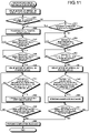
- FIG. 7 is a processing flowchart of an ECU in the case of receiving data from an external sensor unit that functions as a gate sensor;
- FIG. 8 is a processing flowchart of the ECU in the case of receiving data from an external sensor unit that functions as a road sensor;
- FIG. 9 is a processing flowchart of the ECU in the case of receiving data from an external sensor unit that functions as a curve sensor;
- FIG. 10 is a processing flowchart of the ECU in the case of receiving data from an external sensor unit that functions as a boundary-location sensor;
- FIG. 11 is a processing flowchart of the ECU in the case of receiving data from an external sensor unit that functions as a parking space sensor;
- FIG. 12 is a diagram illustrating a modification of the first embodiment
- FIG. 13 is a processing flowchart of an ECU in a second embodiment in the case of receiving data from an external sensor unit that functions as a parking space sensor;
- FIG. 14 is an explanatory diagram of the operation in the second embodiment.
- a vehicle 1 may, for example, be an automobile including an internal combustion engine (not illustrated) as a drive source, that is, an internal combustion engine automobile, an automobile including an electric motor (not illustrated) as a drive source, that is, an electric automobile or a fuel cell automobile, a hybrid automobile including both as drive sources, or an automobile including any other drive source.
- an internal combustion engine not illustrated
- an electric motor not illustrated
- a drive source that is, an electric automobile or a fuel cell automobile
- a hybrid automobile including both as drive sources or an automobile including any other drive source.
- the vehicle 1 may incorporate various transmissions, or various devices such as systems or parts or components required for driving the internal combustion engine or the electric motor. Systems, numbers, and layout of devices involving with driving of wheels 3 of the vehicle 1 can be set variously.
- FIG. 1 is an illustrative perspective view of the vehicle interior partially transparent in the embodiment.
- FIG. 2 is an illustrative plan view (bird's eye view) of the vehicle in the embodiment.
- a vehicle body 2 of the vehicle 1 defines a vehicle interior 2 a in which occupants (not illustrated) ride.
- a steering 4 , an acceleration operator 5 , a brake operator 6 , and a transmission operator 7 are placed inside the vehicle interior 2 a , facing a seat 2 b of a driver as the occupant.
- the steering 4 is, for example, a steering wheel that protrudes from a dashboard 24 .
- the acceleration operator 5 is, for example, an accelerator pedal located at a driver's foot.
- the brake operator 6 is, for example, a brake pedal located at the driver's foot.
- the transmission operator 7 is, for example, a shift lever that protrudes from a center console.
- the steering 4 , the acceleration operator 5 , the brake operator 6 , and the transmission operator 7 are not limited to such examples.
- a display device 8 as a display output, and an audio output device 9 as an audio output are placed in the vehicle interior 2 a .
- the display device 8 is, for example, a liquid crystal display (LCD) or an organic electroluminescent display (OELD).
- the audio output device 9 is, for example, a speaker.
- the display device 8 is covered with a transparent operation input 10 , such as a touch panel. The occupant can view an image displayed on the screen of the display device 8 through the operation input 10 .
- the occupant can touch, push, or move the operation input 10 at a position corresponding to the image displayed on the screen of the display device 8 with his or her finger, for example.
- the display device 8 , the audio output device 9 , and the operation input 10 are included in a monitor device 11 located at a vehicle-width center, i.e., a horizontal center of the dashboard 2 .
- the monitor device 11 can include an operation input (not illustrated), such as a switch, a dial, a joystick, and a pushbutton.
- Another audio output device may be disposed at any location in the vehicle interior 2 a , other than the monitor device 11 , or the audio output device 9 of the monitor device 11 and another audio output device may output audio.
- the monitor device 11 may double as, for example, a navigation system and an audio system.
- FIG. 3 is an illustrative block diagram of a configuration of a parking assist system in the embodiment.
- the vehicle 1 includes a steering system 13 which steers at least two wheels (front wheels 3 F and rear wheels 3 R) 3 .
- the steering system 13 includes an actuator 13 a and a torque sensor 13 b .
- the steering system 13 is electrically controlled by, for example, an electronic control unit (ECU) 14 to thereby operate the actuator 13 a .
- the steering system 13 is configured as, for example, an electric power steering system or a steer-by-wire (SBW) system.
- the steering system 13 uses the actuator 13 a to add torque, i.e., assist torque, to the steering 4 for aiding a steering force or uses the actuator 13 a to steer the wheels 3 .
- the actuator 13 a may steer one wheel 3 or two or more wheels 3 .
- the torque sensor 13 b detects, for example, torque applied by the driver to the steering 4 .
- the vehicle body 2 is provided with, for example, four imagers 15 a to 15 d , as a plurality of imagers 15 .
- the imagers 15 are, for example, digital cameras that incorporate an image sensor, such as a charge coupled device (CCD) or a CMOS image sensor (CIS).
- the imagers 15 can output moving image data at a given frame rate.
- the imagers 15 each include a wide-angle lens or a fisheye lens and can image a horizontal range of, for example, 140 degrees to 190 degrees.
- the imagers 15 have an obliquely downward optical axis.
- the imagers 15 sequentially generate images of an ambient environment around the vehicle body 2 including a road surface on which the vehicle 1 is movable and a parkable area of the vehicle 1 , and output image data.
- the imager 15 a is located, for example, at a rear end 2 e of the vehicle body 2 on a wall below a door 2 h of a rear trunk.
- the imager 15 b is located at a right end 2 f of the vehicle body 2 , for example, on a right-side side mirror 2 g .
- the imager 15 c is located, for example, on the front side of the vehicle body 2 , i.e., at a front end 2 c in a vehicle lengthwise direction, for example, at a front bumper.
- the imager 15 d is located, for example, on the left side of the vehicle body 2 , i.e., on a left end 2 d in the vehicle width direction at a side mirror 2 g being a left-side protrusion.
- the ECU 14 performs computation and image processing to the image data generated by the imagers 15 to be able to generate an image with a wider viewing angle and a virtual bird's eye view image of the vehicle 1 viewed from above.
- the bird's eye view image may be referred to also as a planar image.
- the ECU 14 also identifies from the images of the imagers 15 partition lines drawn on the road surface around the vehicle 1 to thereby detect (extract) a parking section indicated by the partition lines.
- the vehicle body 2 is provided with, for example, four ranging sensors 16 a to 16 d and eight ranging sensors 17 a to 17 h , as a plurality of ranging sensors 16 and 17 .
- the ranging sensors 16 and 17 are, for example, sonars that emit ultrasonic waves and detect reflected waves thereof.
- the sonar may be referred to as a sonar sensor or an ultrasonic wave detector.
- the ranging sensors 16 and 17 are an exemplary detector that detects an object.
- the ranging sensors 17 may be used in detecting, for example, an object in a relatively short distance and the ranging sensors 16 may be used in detecting, for example, an object in a relatively longer distance than the ranging sensors 17 .
- the ranging sensors 17 may be used in detecting, for example, an object ahead and behind the vehicle 1 and the ranging sensors 16 may be used in detecting an object lateral to the vehicle 1 .
- the ranging sensors 16 are connected to ranging communicators 16 X, respectively.
- the ranging communicators 16 X determine, from detection outputs from the ranging sensors 16 , presence or absence of an object such as an obstacle located around the vehicle 1 and measures a distance to the object.
- the ranging communicators 16 X also communicate with an outside via the ranging sensors 16 .
- the ranging sensors 17 are connected to ranging communicators 17 X, respectively.
- the ranging communicators 17 X determine, from detection outputs from the ranging sensors 17 , presence of an object such as an obstacle located around the vehicle 1 and measures a distance to the object.
- the ranging communicators 17 X also communication with an outside via the ranging sensors 17 .
- the ECU 14 can determine whether there is an obstacle or other objects around the vehicle 1 and acquire the distance to the object from the results of measurement by the ranging communicators 16 X and 17 X.
- the ECU 14 can communicate with an external ranging communicator installed in, for example, a parking lot.
- a brake system 18 in the parking assist system 100 , a brake system 18 , a steering angle sensor 19 , an accelerator sensor 20 , a shift sensor 21 , a wheel speed sensor 22 , and other elements are electrically connected to one another via an intra-vehicle network 23 being an electric communication line, in addition to the ECU 14 , the monitor device 11 , the steering system 13 , the ranging sensors 16 and 17 , and the ranging communicators 16 X and 17 X.
- the intra-vehicle network 23 is configured as, for example, a controller area network (CAN).
- the intra-vehicle network 23 may be configured as a local interconnect network (LIN) or another network.
- the ranging sensors 16 and 17 may be connected directly to the ECU 14 via the LIN.
- the ECU 14 can transmit a control signal over the intra-vehicle network 23 to control the steering system 13 and the brake system 18 .
- the ECU 14 can also receive, via the intra-vehicle network 23 , results of detection by, for example, the torque sensor 13 b , a brake sensor 18 b , the steering angle sensor 19 , the ranging communicators 16 X, the ranging communicators 17 X, the accelerator sensor 20 , the shift sensor 21 , and the wheel speed sensor 22 , and operation signals of the operation input 10 .
- the ECU 14 includes, for example, a central processing unit (CPU) 14 a , a read only memory (ROM) 14 b , a random access memory (RAM) 14 c , a display controller 14 d , an audio controller 14 e , a solid state drive (SSD) 14 f (flash memory), and an operation unit 14 g to which commands to the ECU 14 are input.
- CPU central processing unit
- ROM read only memory
- RAM random access memory
- SD solid state drive
- flash memory flash memory
- the CPU 14 a can perform various computations and control, including image processing to images displayed on the display devices 8 and 12 , determination of a target moving position of the vehicle 1 , calculation of a moving path of the vehicle 1 , determination on interference or no interference with an object, and activation and deactivation of automatic control over the vehicle 1 .
- the CPU 14 a can load an installed program from a nonvolatile storage device, such as the ROM 14 b , and perform computation in accordance with the program.
- the RAM 14 c temporarily stores various types of data used in the calculation by the CPU 14 a.
- the display controller 14 d mainly performs image processing to the image data generated by the imagers 15 , and image composition of the image data to display on the display device 8 .
- the audio controller 14 e mainly processes audio data to output from the audio output device 9 , among the computation by the ECU 14 .
- the SSD 14 f is a rewritable nonvolatile storage and can store data at power-off of the ECU 14 .
- the CPU 14 a , the ROM 14 b , the RAM 14 c , and other parts can be integrated into a single package.
- the ECU 14 may include, instead of the CPU 14 a , a digital signal processor (DSP) or another logic operation processor, and a logic circuit.
- the ECU 14 may include a hard disk drive (HDD) instead of the SSD 14 f , or the SSD 14 f or the HDD may be separated from the ECU 14 .
- DSP digital signal processor
- HDD hard disk drive
- the brake system 18 is configured as, for example, an anti-lock brake system (ABS) that prevents the brake from locking, an electronic stability control (ESC) that prevents the vehicle 1 from skidding during cornering, an electric brake system that boosts a braking force (performs brake assist), or a brake-by-wire (BBW).
- ABS anti-lock brake system
- ESC electronic stability control
- BBW brake-by-wire
- the brake system 18 applies a braking force to the wheels 3 and the vehicle 1 via an actuator 18 a .
- the brake system 18 can perform various types of control by detecting brake lockup, idling of the wheels 3 , and an indication of skidding from a difference in rotational speed between the left and right wheels 3 .
- the brake sensor 18 b is, for example, a sensor that detects the position of a movable part of the brake operator 6 .
- the brake sensor 18 b can detect the position of the brake pedal as the movable part of the brake operator 6 .
- the brake sensor 18 b includes a displacement sensor.
- the steering angle sensor 19 is, for example, a sensor that detects a steering amount of the steering 4 , such as a steering wheel.
- the steering angle sensor 19 includes, for example, a Hall element.
- the ECU 14 acquires, from the steering angle sensor 19 , the steering amount of the steering 4 by the driver and the steering amount of each of the wheels 3 during automatic steering for various types of control.
- the steering angle sensor 19 detects a rotation angle of a rotary part of the steering 4 .
- the steering angle sensor 19 is an exemplary angle sensor.
- the accelerator sensor 20 is, for example, a sensor that detects the position of a movable part of the acceleration operator 5 .
- the accelerator sensor 20 can detect the position of the accelerator pedal as the movable part of the acceleration operator 5 .
- the accelerator sensor 20 includes a displacement sensor.
- the shift sensor 21 is, for example, a sensor that detects the position of a movable part of the transmission operator 7 .
- the shift sensor 21 can detect the position of, for example, a lever, an arm, or a button of the transmission operator 7 as the movable part.
- the shift sensor 21 may include a displacement sensor or may be formed as a switch.
- the wheel speed sensor 22 is a sensor that detects amount of rotation or rotation speed per unit time of each of the wheels 3 .
- the wheel speed sensor 22 outputs as a sensor value a wheel-speed pulse count being the detected rotation speed.
- the wheel speed sensor 22 may include, for example, a Hall element.
- the ECU 14 calculates, for example, an amount of movement of the vehicle 1 from the sensor value acquired from the wheel speed sensor 22 for various types of control.
- the wheel speed sensor 22 may be included in the brake system 18 . In this case, the ECU 14 acquires results of the detection by the wheel speed sensor 22 via the brake system 18 .
- Configurations, arrangement, and electrical connections of the various types of sensors and actuators described above are merely exemplary and may be set (altered) variously.
- the following describes configuration of the ranging communicators 16 X and the ranging communicators 17 X.
- the ranging communicators 16 X and the ranging communicators 17 X have the same configuration, therefore, the following describes the ranging communicator 17 X as an example.
- FIG. 4 is a schematic configuration block diagram of the ranging communicator.
- the ranging communicator 17 X includes a carrier signal generator 41 , a modulator 42 , a transmission amplifier 43 , and a changeover switch (SW) 44 .
- the carrier signal generator 41 generates a carrier signal (carrier wave signal) for use in communication.
- the modulator 42 modulates the carrier signal by a given modulation scheme (e.g., PSK modulation, FSK modulation, and ASK modulation) on the basis of transmission data DT from the ECU 14 .
- the transmission amplifier 43 amplifies an output from the modulator 42 for output.
- the changeover switch 44 changes over between transmission of a transmission signal ST from the transmission amplifier 43 to the ranging sensors 17 and an output of a reception signal from the ranging sensors 17 to a reception amplifier 45 .
- the ranging communicator 17 X further includes the reception amplifier 45 , a carrier signal regenerator 46 , a demodulator 47 , a low-pass filter (LPF) 48 , a bit discriminator 49 , and a ranging calculator 50 .
- the reception amplifier 45 amplifies a reception signal from the changeover switch 44 and outputs the resultant as a reception signal SR.
- the carrier signal regenerator 46 regenerates a carrier signal from the reception signal SR output from the reception amplifier 45 and outputs the resultant carrier signal.
- the demodulator 47 demodulates the reception signal SR in accordance with the carrier signal output from the carrier signal regenerator 46 and outputs the resultant as a demodulated reception signal.
- the LPF 48 removes harmonic noise from the demodulated reception signal.
- the bit discriminator 49 performs bit discrimination of the demodulated reception signal and outputs the resultant as received data DR to the ECU 14 .
- the ranging calculator 50 determines presence or absence of an object such as an obstacle, and calculates a distance to the object from a difference in timing between transmission of the transmission signal ST and reception of the reception signal SR and outputs the resultant as distance data DD to the ECU 14 .
- FIG. 5 is a schematic illustrative view of the configuration of a parking lot system.
- a parking lot system 150 is installed in a given location in a parking lot.
- the parking lot system 150 includes, for example, a plurality of external sensor units SU 1 to SU 10 and a server 51 .
- the external sensor units SU 1 to SU 10 each have the same or similar configuration as the ranging sensors 17 and the ranging communicator 17 X illustrated in FIG. 4 .
- the server 51 is communicably connected to the external sensor units SU 1 to SU 10 via a communication network NW to control the external sensor units SU 1 to SU 10 .
- the ECU 14 may store map information of the parking lot in advance, for example, and the external sensor units SU 1 to SU 10 may include their position information. In such a case the parking lot system 150 can provide path guidance to the vehicle without communicating with, for example, the server 51 via the communication network NW.
- the locations of the external sensor units SU 1 to SU 10 are exemplary.
- the external sensor unit SU 1 is defined to be located at a gate GT of the parking lot and the external sensor unit SU 2 is defined to be located in the middle of a vehicle pathway RT within the parking lot.
- the external sensor unit SU 3 is defined to be located at a curve of the vehicle pathway.
- the external sensor unit SU 4 is defined to be located at the boundary of the vehicle pathway RT.
- the external sensor unit SU 5 is defined to be located before a parking space PS to be a destination of path guidance.
- the external sensor unit SU 6 and the external sensor unit SU 7 are defined to be located at both ends of the entrance of the parking space PS.
- the external sensor unit SU 8 is defined to be located in the middle of the parking space PS.
- the external sensor unit SU 9 and the external sensor unit SU 10 are defined to be located at both ends of the dead end of the parking space PS.
- the external sensor unit SU 6 and the external sensor unit SU 7 function as parking line sensors.
- the external sensor unit SU 8 functions as an in-parking-space sensor.
- the external sensor unit SU 9 and the external sensor unit SU 10 function as parking dead-end sensors.
- the following describes a data format of communication data exchanged between the ranging communicators 16 X and the ranging communicators 17 X, and the external sensor units SU 1 to SU 10 .
- FIG. 6 is an illustrative view of an exemplary data format of communication data.
- Communication data 60 includes preamble data 61 , transmission source ID data 62 , transmission destination ID data 63 , transmission dataset data 64 , and error check data 65 .
- the preamble data 61 is for synchronizing communication.
- the transmission source ID data 62 contains a transmission source ID (transmission source identification information) for identifying a device being the transmission source.
- the transmission destination ID data 63 stores a transmission destination ID (transmission destination identification information) for identifying a device being a transmission destination.
- the transmission dataset data 64 includes data required for actual communication such as various types of data (communication control data such as requested data and response data, operation control data, control data for message display).
- the error check data 65 contains an error check code for checking error in the communication data 60 .
- the transmission destination ID data 6362 contains an ID that represents broadcast communication for transmission to a large indefinite number of destinations.
- the external sensor units SU 1 to SU 10 repeatedly issue communication requests to a large indefinite number of destinations at given timing.
- the ECU 14 transmits a communication response to any of the external sensor units SU 1 to SU 10 having issued the communication request. This starts the communication.
- the ranging sensor 16 or the ranging sensor 17 receives a communication request from the external sensor unit SU 1 functioning as a gate sensor, and the ranging communicator 16 X or the ranging communicator 17 X associated with the ranging sensor 16 or 17 starts communication with the external sensor unit SU 1 .
- FIG. 7 is a processing flowchart of the ECU when receiving data from an external sensor unit functioning as a gate sensor.
- the ECU 14 executes the same processing irrespective of which one of the ranging communicator 16 X and the ranging communicator 17 X associated with the ranging sensor 16 or the ranging sensor 17 performs communication.
- the ECU 14 receives a parking-lot map including an expected running path and parkable space information (Step S 11 ).
- the ECU 14 determines whether the vehicle 1 is in automatic driving (Step S 12 ).
- Step S 12 After determining at Step S 12 that the vehicle 1 is not in automatic driving (No at Step S 12 ), the ECU 14 presents guidance information to the parking space and information on the parkable space PS (Step S 16 ), ending the processing.
- the ECU 14 calculates and determines the position of the passing vehicle 1 from the distance between the external sensor unit SU 1 and the ranging sensor 16 or 17 located communicably with the external sensor unit SU 1 (Step S 13 ).
- the ECU 14 determines whether an error in position of the vehicle 1 with respect to the expected running path is equal to or greater than a given value (Step S 14 ).
- Step S 14 After determining at Step S 14 that the position error of the vehicle 1 with respect to the expected running path is equal to or greater than the given value, the ECU 14 drives the actuator 13 a via the steering system 13 to correct the error so that the vehicle 1 actually runs on the path close to the expected running path, ending the processing (Step S 15 ).
- Step S 14 After determining at Step S 14 that the position error of the vehicle 1 with respect to the expected running path is smaller than the given value (No at Step S 14 ), the vehicle can continuously run as it currently is, thus, the ECU 14 ends the processing.
- FIG. 8 is a processing flowchart of the ECU when receiving data from an external sensor unit that functions as a road sensor.
- the ECU 14 determines whether the vehicle 1 is in automatic driving (Step S 21 ).
- Step S 21 After determining at Step S 21 that the vehicle 1 is not in automatic driving (No at Step S 21 ), the ECU 14 ends the processing.
- Step S 21 After determining at Step S 21 that the vehicle 1 is in automatic driving (Yes at Step S 21 ), the ECU 14 calculates and determines the position of the passing vehicle 1 from the distance between the external sensor unit SU 2 and the ranging sensor 16 or 17 located communicably with the external sensor unit SU 2 (Step S 22 ).
- Step S 23 After determining at Step S 23 that the position error of the vehicle 1 with respect to the expected running path is equal to or greater than the given value, the ECU 14 drives the actuator 13 a via the steering system 13 to correct the error so that the vehicle 1 actually runs on the path close to the expected running path, ending the processing (Step S 24 ).
- Step S 23 After determining at Step S 23 that the position error of the vehicle 1 with respect to the expected running path is smaller than the given value (No at Step S 23 ), the vehicle 1 can continue running as it currently is, so that ECU 14 ends the processing.
- FIG. 9 is a processing flowchart of the ECU when receiving data from an external sensor unit functioning as a curve sensor.
- the ECU 14 receives curve guidance information indicating that the vehicle 1 is approaching a curve on the running path (Step S 31 ).
- the ECU 14 calculates, from the distance between the external sensor unit SU 3 and the ranging sensor 16 or 17 located communicably with the external sensor unit SU 3 , the position and the angle of the passing vehicle 1 (Step S 32 ).
- the ECU 14 determines whether the vehicle 1 can go around (successfully corners) the curve, from the position and the angle of the passing vehicle 1 , considering the speed based on the output from the wheel speed sensor 22 and the steering amount of the steering 4 based on the output from the steering angle sensor 19 (Step S 33 ).
- Step S 33 After determining at Step S 33 that the vehicle 1 can go around (successfully corners) the curve (Yes at Step S 33 ), the vehicle 1 can continue running as it currently is, so that ECU 14 ends the processing.
- Step S 34 After determining at Step S 33 that the vehicle 1 cannot go around (fails in cornering) the curve (No at Step S 33 ), the ECU 14 determines whether the vehicle 1 is in automatic driving (Step S 34 ).
- Step S 34 After determining at Step S 34 that the vehicle 1 is not in automatic driving (No at Step S 34 ), the ECU 14 presents alarm information that the vehicle 1 may be unable to go around (fail in cornering) (Step S 37 ), ending the processing.
- Step S 35 After determining at Step S 35 that the position error of the vehicle 1 with respect to the expected running path is equal to or greater than the given value, the ECU 14 drives the actuator 13 a via the steering system 13 to correct the error so that the vehicle 1 actually runs on the path close to the expected running path and more stably corners, ending the processing (Step S 36 ).
- Step S 35 After determining at Step S 35 that the position error of the vehicle 1 with respect to the expected running path is smaller than the given value (No at Step S 35 ), the vehicle 1 can continue driving as it currently is, so that ECU 14 ends the processing.
- FIG. 10 is a processing flowchart of the ECU when receiving data from an external sensor unit that functions as a boundary-location sensor.
- the ECU 14 receives boundary information representing that the vehicle 1 has arrived at a point at which the vehicle 1 can no longer continue to run (e.g., an entry point to a driving prohibited road and a spot in which a wall, with which the vehicle 1 may collide, stands) (Step S 41 ).
- the ECU 14 issues a notice by voice through the audio output device 9 or through the display device 8 or the display device 12 .
- Step S 42 the ECU 14 determines whether the vehicle 1 is in automatic driving.
- Step S 42 After determining at Step S 42 that the vehicle 1 is not in automatic driving (No at Step S 42 ), the ECU 14 ends the processing.
- the ECU 14 calculates and determines the position of the passing vehicle 1 from the distance between the external sensor unit SU 4 and the ranging sensor 16 or 17 located communicably with the external sensor unit SU 4 (Step S 43 ).
- the ECU 14 determines whether a position error of the vehicle 1 with respect to the expected running path is equal to or greater than a given value (Step S 44 ).
- Step S 44 After determining at Step S 44 that the position error of the vehicle 1 with respect to the expected running path is equal to or greater than the given value, the ECU 14 drives the actuator 13 a via the steering system 13 to correct the error so that the vehicle 1 actually runs on the path close to the expected running path, ending the processing (Step S 45 ).
- Step S 44 After determining at Step S 44 that the position error of the vehicle 1 with respect to the expected running path is smaller than the given value (No at Step S 44 ), the vehicle 1 can continue running as it currently is, so that ECU 14 ends the processing.
- FIG. 11 is a processing flowchart of the ECU when receiving data from an external sensor unit functioning as a parking-space sensor.
- the ECU 14 receives parking-space approaching information representing the arrival of the vehicle 1 in the vicinity of the assigned parkable space PS (Step S 51 ).
- the ECU 14 issues notification by voice via the audio output device 9 or via the display device 8 or the display device 12 that the vehicle 1 has arrived in the vicinity of the assigned parkable space PS.
- Step S 52 the ECU 14 determines whether the vehicle 1 is in automatic driving.
- Step S 53 After determining at Step S 52 that the vehicle 1 is in automatic driving (Yes at Step S 52 ), the ECU 14 makes a transition of the operation mode of the vehicle 1 to an automatic parking mode (Step S 53 ).
- the ECU 14 then controls the steering system 13 and the brake system 18 to automatically move the vehicle 1 into the parking space PS via a position P 5 in the parking lot, transitions to the automatic parking mode for moving to the parking position, and performs automatic parking control.
- the ECU 14 next determines whether to have received data from the external sensor unit SU 6 and the external sensor unit SU 7 functioning as parking line sensors, specifically, whether the vehicle 1 has reached the parking space PS (Step S 54 ).
- the ECU 14 After determining no receipt of the data from the external sensor unit SU 6 and the external sensor unit SU 7 functioning as the parking line sensors at Step S 54 (No at Step S 54 ), the ECU 14 is set in a standby state.
- the ECU 14 After determining receipt of the data from the external sensor unit SU 6 and the external sensor unit SU 7 functioning as the parking line sensors at Step S 54 (Yes at Step S 54 ), the ECU 14 determines whether to have received data from the external sensor unit SU 8 functioning as the in-parking-space sensor, specifically, whether the vehicle 1 has arrived inside the parking space PS (Step S 55 ).
- the ECU 14 After determining no receipt of the data from the external sensor unit SU 8 as the in-parking-space sensor at Step S 55 (No at Step S 55 ), the ECU 14 is set in a standby state.
- Step S 55 After determining receipt of the data from the external sensor unit SU 8 as the in-parking-space sensor at Step S 55 (Yes at Step S 55 ), the ECU 14 issues a guidance by voice or a notification via the display device 8 or the display device 12 that the vehicle 1 has arrived inside the parking space PS (Step S 56 ).
- Step S 57 After determining at Step S 57 that the position error of the vehicle 1 with respect to the expected running path is smaller than the given value, the ECU 14 determines that the vehicle 1 can continue running as it currently is and proceeds to Step S 59 .
- Step S 57 After determining at Step S 57 that the position error of the vehicle 1 with respect to the expected running path is equal to or greater than the given value, the ECU 14 drives the actuator 13 a via the steering system 13 to correct the error so that the vehicle 1 actually runs on the path close to the expected running path, ending the processing (Step S 58 ).
- the ECU 14 next determines whether to have received data from the external sensor unit SU 9 and the external sensor unit SU 10 functioning as parking dead-end sensors, specifically, whether the vehicle 1 has reached the parking position at the dead end of the parking space PS (Step S 59 ).
- Step S 59 After determining no receipt of the data from the external sensor unit SU 9 and the external sensor unit SU 10 functioning as the parking dead-end sensors at Step S 59 (No at Step S 59 ), the ECU 14 determines non-completion of the parking and returns to Step S 57 and repeats the same operation as above to continue the automatic parking control.
- Step S 59 After determining receipt of the data from the external sensor unit SU 9 and the external sensor unit SU 10 functioning as the parking dead-end sensors at Step S 59 (Yes at Step S 59 ), the ECU 14 issues a voice guidance or a notification via the display device 8 or the display device 12 that the vehicle 1 has reached the parking position at the dead end of the parking space PS, and places the vehicle 1 in a parking state, ending the processing (Step S 60 ).
- Step S 61 the ECU 14 determines whether the vehicle 1 includes the automatic parking mode as an operation mode.
- Step S 61 After determining at Step S 61 that the vehicle 1 includes the automatic parking mode as an operation mode (Yes at Step S 61 ), the ECU 14 returns to Step S 53 , repeats the same operation in the automatic driving as above, and places the vehicle 1 in the parking state, ending the processing (Step S 53 to Step S 60 ).
- Step S 61 After determining at Step S 61 that the vehicle 1 includes no automatic parking mode as an operation mode (No at Step S 61 ), the ECU 14 determines whether to have received data from the external sensor unit SU 6 and the external sensor unit SU 7 functioning as the parking line sensors, specifically, whether the vehicle 1 has reached the parking space PS (Step S 62 ).
- the ECU 14 After determining no receipt of the data from the external sensor unit SU 6 and the external sensor unit SU 7 functioning as the parking line sensors at Step S 62 (No at Step S 62 ), the ECU 14 enters a standby state.
- the ECU 14 After determining receipt of data from the external sensor unit SU 6 and the external sensor unit SU 7 functioning as the parking line sensors at Step S 62 (Yes at Step S 62 ), the ECU 14 determines whether to have received data from the external sensor unit SU 8 functioning as the in-parking-space sensor, specifically, whether the vehicle 1 has arrived inside the parking space PS (Step S 63 ).
- the ECU 14 After determining no receipt of the data from the external sensor unit SU 8 functioning as the in-parking-space sensor at Step S 63 (No at Step S 63 ), the ECU 14 enters a standby state.
- Step S 64 After determining receipt of the data from the external sensor unit SU 8 functioning as the in-parking-space sensor at Step S 63 (Yes at Step S 63 ), the ECU 14 issues a voice guidance or a notification via the display device 8 or the display device 12 that the vehicle 1 has arrived inside the parking space PS (Step S 64 ).
- the ECU 14 calculates, from the distance between the external sensor unit SU 8 and the ranging sensor 16 or 17 located communicably with the external sensor unit SU 8 , the position of the passing vehicle 1 and determines whether the position error of the vehicle 1 with respect to the expected running path is equal to or greater than a given value (Step S 65 ).
- Step S 65 After determining at Step S 65 that the position error of the vehicle 1 with respect to the expected running path is smaller than the given value (No at Step S 65 ), the ECU 14 determines that the vehicle 1 can continue running as it currently is, and proceeds to Step S 67 .
- Step S 65 After determining at Step S 65 that the position error of the vehicle 1 with respect to the expected running path is equal to or greater than the given value (Yes at Step S 65 ), the ECU 14 notifies the driver of how to maneuver the steering by voice or via the display device 8 or the display device 12 so that the driver can actually drive the vehicle 1 on the path close to the expected running path (Step S 66 ).
- the ECU 14 next determines whether to have received data from the external sensor unit SU 9 and the external sensor unit SU 10 functioning as the parking dead-end sensors, specifically, whether the vehicle 1 has reached the parking position at the dead end of the parking space PS (Step S 67 ).
- Step S 67 After determining no receipt of the data from the external sensor unit SU 9 and the external sensor unit SU 10 functioning as the parking dead-end sensors at Step S 67 (No at Step S 67 ), the ECU 14 determines non-completion of the parking, and returns to Step S 65 and repeats the same operation as above to continue the automatic parking control.
- the ECU 14 After determining receipt of the data from the external sensor unit SU 9 and the external sensor unit SU 10 functioning as the parking dead-end sensors at Step S 67 (Yes at Step S 67 ), the ECU 14 issues a voice guidance or a notification via the display device 8 or the display device 12 that the vehicle 1 has reached the parking position at the dead end of the parking space PS, ending the processing.
- the first embodiment enables automatic driving of the vehicle 1 to a parking space for parking, even to a new parking space, through simple data communication with the external sensor units SU 1 to SU 10 , which eliminates the need for the driver to look around for a parking space. This can greatly reduce driver's time and effort.
- the first embodiment can efficiently provide guidance to the parking space, thereby reducing a driver's load.
- the first embodiment is effective in a parking lot where the driver cannot find a parkable space at first view, particularly in a multistory parking lot with poor visibility or in a plane parking lot in the suburbs too large to view the entire area.
- FIG. 12 is a diagram illustrating a modification of the first embodiment.
- the first embodiment has described the external sensor units installed in the parking space PS, including the external sensor units SU 6 and SU 7 functioning as the parking line sensors, the external sensor unit SU 8 functioning as the in-parking-space sensor, and the external sensor units SU 9 and SU 10 functioning as the parking dead-end sensors.
- the external sensor units may include four external sensor units SU 6 , SU 7 , SU 9 , and SU 10 functioning as the boundary-location sensors having the same or similar directivity as the external sensor unit SU 4 , described in the first embodiment.
- the external sensor unit SU 6 function as the external sensor units SU 6 and SU 7 functioning as the parking line sensors in the first embodiment
- the external sensor units SU 7 and SU 9 function as the external sensor unit SU 8 functioning as the in-parking-space sensor in the first embodiment
- the external sensor unit SU 10 functions as the external sensor unit SU 9 and the external sensor unit SU 10 functioning as the parking dead-end sensors in the first embodiment.
- Such a configuration enables decrease in the number of external sensor units installed in the parking space and common use of the in-parking-space sensor in the adjacent parking spaces (e.g., in the neighboring parking space on the right side, the external sensor unit SU 7 is commonly usable as the in-parking-space sensor between the two parking spaces). This can further reduce installation cost.
- the second embodiment differs from the first embodiment in operation after the vehicle arrives in the vicinity of the parking space PS.
- FIG. 13 is a processing flowchart of the ECU in the second embodiment when receiving data from an external sensor unit that functions as a parking space sensor.
- FIG. 14 is a diagram illustrating the operation in the second embodiment.
- the ECU 14 receives parking space PS approaching information that the vehicle 1 has arrived in the vicinity of the assigned parkable space PS.
- the ECU 14 issues a notification by voice through the audio output device 9 or through the display device 8 or the display device 12 that the vehicle 1 has arrived in the vicinity of the assigned parkable space PS (Step S 71 ).
- Step S 72 the ECU 14 of the vehicle 1 proceeds to a parking operation (Step S 72 ) and determines whether to have received data from any of the external sensor unit SU 6 , the external sensor unit SU 7 , and the external sensor unit SU 10 installed in the parking space PS (Step S 73 ).
- the ECU 14 After determining no receipt of the data from any of the external sensor unit SU 6 , the external sensor unit SU 7 , and the external sensor unit SU 10 installed in the parking space PS at Step S 73 (No at Step S 73 ), the ECU 14 enters a standby state.
- the ECU 14 After determining receipt of the data from any of the external sensor unit SU 6 , the external sensor unit SU 7 , and the external sensor unit SU 10 installed in the parking space PS at Step S 73 (Yes at Step S 73 ), the ECU 14 determines whether to have received a parking space map representing the locations of the external sensor unit SU 6 , the external sensor unit SU 7 , and the external sensor unit SU 10 in the parking space PS (Step S 74 ).
- Step S 74 After determining receipt of the parking space map at Step S 74 (Yes at Step S), the ECU 14 determines whether to have received data from two or more of the external sensor unit SU 6 , the external sensor unit SU 7 , and the external sensor unit SU 10 in the parking space PS (Step S 75 ). After determining no receipt of the parking space map at Step S 74 (No at Step S 74 ), the ECU 14 issues an alarm, controls the brake system 18 to perform braking control over the vehicle 1 to temporarily stop, and prompts the driver to drive the vehicle to the parking space PS by himself or herself (Step S 80 ), and proceeds to Step S 79 .
- Step S 75 After determining no receipt of the data from two or more external sensor units at Step S 75 (No at Step S 75 ), the ECU 14 returns to Step S 72 and repeats the same operation as above in order to continue the operation.
- the ECU 14 After determining receipt of the data from two or more external sensor units at Step S 75 (Yes at Step S 75 ), the ECU 14 is now able to calculate the posture of the vehicle 1 on the basis of the received data from the external sensor units (information on the distance to each of the external sensor units). Thus, the ECU 14 estimates the position of the axis of a parking position (position of the axis of an optimum parking position in the parking space PS) on the basis of the received data (Step S 76 ).
- the position of the axis of the parking position is defined to be a lengthwise axis CA of the vehicle 1 parked in the optimum parking position (indicated by the broken line in the FIG. 14 ).
- the ECU 14 next estimates a positional offset and an angular offset between the position of the lengthwise axis CA of the vehicle 1 parked in the optimum parking position (indicated by the broken line in the FIG. 14 ) and the actual position of the axis CA of the vehicle 1 (indicated by the solid line in FIG. 14 ) (Step S 77 ).
- the ECU 14 performs guidance control over the vehicle 1 (e.g., automatic parking control or steering maneuver guidance) on the basis of the positional offset amount and the angular offset amount (Step S 78 ).
- the ECU 14 determines whether the vehicle 1 has arrived in a target parking position that corresponds to the estimated position of the axis of the parking position at Step S 76 and is at the rear end of the parking position (in the example illustrated in FIG. 14 , the position at which the ranging sensors 16 and 17 , which are installed on the rear side of the vehicle 1 , can receive directional ultrasonic waves SS from the external sensor unit SU 10 ) (Step S 79 ).
- the target parking position may be set to the position at which an axis RWA of the rear wheel of the vehicle 1 reaches a given position, or to a given position CP 0 of the vehicle 1 falling within a given range from a target position CP 1 .
- Step S 79 After determining at Step S 79 that the vehicle 1 has not reached the target parking position (No at Step S 79 ), the ECU 14 returns to Step S 72 again and repeats the same operation as above.
- Step S 79 After determining at Step S 79 that the vehicle 1 has not reached the target parking position, the ECU 14 ends the processing.
- the second embodiment can attain similar or same effects as the first embodiment, and determines, for the control, whether the given target parking position of the vehicle 1 is located at the axis of the parking position, on the basis of the axis CA of the vehicle 1 and the axis RWA of the rear wheel of the vehicle 1 or on the basis of the given position CP 0 of the vehicle 1 .
Abstract
Description
Claims (10)
Applications Claiming Priority (4)
| Application Number | Priority Date | Filing Date | Title |
|---|---|---|---|
| JP2017-065888 | 2017-03-29 | ||
| JPJP2017-065888 | 2017-03-29 | ||
| JP2017065888A JP6834685B2 (en) | 2017-03-29 | 2017-03-29 | Vehicle guidance devices, methods and programs |
| PCT/JP2018/007641 WO2018180160A1 (en) | 2017-03-29 | 2018-02-28 | Vehicle guidance device, method, and program |
Publications (2)
| Publication Number | Publication Date |
|---|---|
| US20200317268A1 US20200317268A1 (en) | 2020-10-08 |
| US11511805B2 true US11511805B2 (en) | 2022-11-29 |
Family
ID=63674865
Family Applications (1)
| Application Number | Title | Priority Date | Filing Date |
|---|---|---|---|
| US16/496,575 Active 2039-09-12 US11511805B2 (en) | 2017-03-29 | 2018-02-28 | Vehicle guidance device, method, and computer program product |
Country Status (4)
| Country | Link |
|---|---|
| US (1) | US11511805B2 (en) |
| JP (1) | JP6834685B2 (en) |
| CN (1) | CN110462701B (en) |
| WO (1) | WO2018180160A1 (en) |
Families Citing this family (7)
| Publication number | Priority date | Publication date | Assignee | Title |
|---|---|---|---|---|
| JP7212486B2 (en) * | 2018-09-26 | 2023-01-25 | フォルシアクラリオン・エレクトロニクス株式会社 | position estimator |
| JP7200623B2 (en) * | 2018-11-27 | 2023-01-10 | 株式会社アイシン | Vehicle guidance systems, on-board equipment, and ground equipment |
| KR102160281B1 (en) * | 2018-12-28 | 2020-09-25 | 주식회사 블루인텔리전스 | Method for guiding path of unmanned autonomous vehicle and assistant system for unmanned autonomous vehicle therefor |
| WO2021033632A1 (en) * | 2019-08-20 | 2021-02-25 | 日立オートモティブシステムズ株式会社 | Vehicle control method and vehicle control device |
| US20230160700A1 (en) * | 2020-03-25 | 2023-05-25 | Robert Bosch Gmbh | Vehicle locating system and vehicle locating device |
| CN112991797B (en) * | 2021-03-08 | 2022-06-14 | 中国科学院计算技术研究所 | Wireless guide rail system based on narrow beams and method for controlling vehicle to run |
| CN113552574B (en) * | 2021-07-13 | 2023-01-06 | 上海欧菲智能车联科技有限公司 | Region detection method and device, storage medium and electronic equipment |
Citations (12)
| Publication number | Priority date | Publication date | Assignee | Title |
|---|---|---|---|---|
| US6671592B1 (en) | 1998-12-18 | 2003-12-30 | Dyson Limited | Autonomous vehicular appliance, especially vacuum cleaner |
| JP2004220197A (en) | 2003-01-10 | 2004-08-05 | Hitachi Ltd | Communication method using radio network and server device to be used for the same |
| US20090279389A1 (en) * | 2008-05-09 | 2009-11-12 | Seiko Epson Corporation | Ultrasonic signal communication device, communication device, communication device for divers, communication system, and communication method |
| US20100042319A1 (en) * | 2008-08-15 | 2010-02-18 | Wu Chih-Jen | Automatic ultrasonic and computer-vision navigation device and method using the same |
| JP2010039870A (en) | 2008-08-06 | 2010-02-18 | Honda Motor Co Ltd | Driving support apparatus |
| JP2010188744A (en) | 2009-02-13 | 2010-09-02 | Clarion Co Ltd | Device, method and program for supporting parking |
| JP2011054116A (en) | 2009-09-04 | 2011-03-17 | Toshiba Corp | Parking lot management device and parking lot management method |
| KR101043044B1 (en) * | 2009-01-23 | 2011-06-21 | (주)카이로넷 | Reference voltage generator for providing reference voltage freefrom supply voltage change |
| JP2014137743A (en) | 2013-01-17 | 2014-07-28 | Denso It Laboratory Inc | Information providing system |
| US20140357213A1 (en) | 2013-05-29 | 2014-12-04 | Fujitsu Ten Limited | Mobile terminal |
| US20160280263A1 (en) | 2015-03-23 | 2016-09-29 | Mitsubishi Electric Corporation | Parking assist apparatus |
| JP2016213551A (en) | 2015-04-30 | 2016-12-15 | 富士通テン株式会社 | Drive assist system and drive assist method |
Family Cites Families (4)
| Publication number | Priority date | Publication date | Assignee | Title |
|---|---|---|---|---|
| JP2007121001A (en) * | 2005-10-26 | 2007-05-17 | Matsushita Electric Ind Co Ltd | Navigation device |
| JP5903373B2 (en) * | 2012-11-21 | 2016-04-13 | 本田技研工業株式会社 | Travel guidance system |
| CN104468043B (en) * | 2014-12-04 | 2019-02-12 | 福建京奥通信技术有限公司 | A kind of pbch convolutional code fast decoding device and method applied to lte |
| DE102015204359A1 (en) * | 2015-03-11 | 2016-09-15 | Robert Bosch Gmbh | Driving a motor vehicle in a parking lot |
-
2017
- 2017-03-29 JP JP2017065888A patent/JP6834685B2/en active Active
-
2018
- 2018-02-28 WO PCT/JP2018/007641 patent/WO2018180160A1/en active Application Filing
- 2018-02-28 CN CN201880021162.XA patent/CN110462701B/en active Active
- 2018-02-28 US US16/496,575 patent/US11511805B2/en active Active
Patent Citations (14)
| Publication number | Priority date | Publication date | Assignee | Title |
|---|---|---|---|---|
| US6671592B1 (en) | 1998-12-18 | 2003-12-30 | Dyson Limited | Autonomous vehicular appliance, especially vacuum cleaner |
| JP2004220197A (en) | 2003-01-10 | 2004-08-05 | Hitachi Ltd | Communication method using radio network and server device to be used for the same |
| US20090279389A1 (en) * | 2008-05-09 | 2009-11-12 | Seiko Epson Corporation | Ultrasonic signal communication device, communication device, communication device for divers, communication system, and communication method |
| JP2010039870A (en) | 2008-08-06 | 2010-02-18 | Honda Motor Co Ltd | Driving support apparatus |
| US20100042319A1 (en) * | 2008-08-15 | 2010-02-18 | Wu Chih-Jen | Automatic ultrasonic and computer-vision navigation device and method using the same |
| KR101043044B1 (en) * | 2009-01-23 | 2011-06-21 | (주)카이로넷 | Reference voltage generator for providing reference voltage freefrom supply voltage change |
| JP2010188744A (en) | 2009-02-13 | 2010-09-02 | Clarion Co Ltd | Device, method and program for supporting parking |
| JP2011054116A (en) | 2009-09-04 | 2011-03-17 | Toshiba Corp | Parking lot management device and parking lot management method |
| JP2014137743A (en) | 2013-01-17 | 2014-07-28 | Denso It Laboratory Inc | Information providing system |
| US20140357213A1 (en) | 2013-05-29 | 2014-12-04 | Fujitsu Ten Limited | Mobile terminal |
| JP2014232411A (en) | 2013-05-29 | 2014-12-11 | 富士通テン株式会社 | Portable terminal, and danger notification system |
| US20160280263A1 (en) | 2015-03-23 | 2016-09-29 | Mitsubishi Electric Corporation | Parking assist apparatus |
| JP2016175620A (en) | 2015-03-23 | 2016-10-06 | 三菱電機株式会社 | Parking assist device |
| JP2016213551A (en) | 2015-04-30 | 2016-12-15 | 富士通テン株式会社 | Drive assist system and drive assist method |
Non-Patent Citations (1)
| Title |
|---|
| International Search Report for PCT/JP2018/007641 dated May 15, 2018 (PCT/ISA/210). |
Also Published As
| Publication number | Publication date |
|---|---|
| CN110462701A (en) | 2019-11-15 |
| JP2018167673A (en) | 2018-11-01 |
| JP6834685B2 (en) | 2021-02-24 |
| US20200317268A1 (en) | 2020-10-08 |
| CN110462701B (en) | 2022-02-22 |
| WO2018180160A1 (en) | 2018-10-04 |
Similar Documents
| Publication | Publication Date | Title |
|---|---|---|
| US11511805B2 (en) | Vehicle guidance device, method, and computer program product | |
| US10752238B2 (en) | Parking assistance device | |
| US9714034B2 (en) | Vehicle control device | |
| EP3124360B1 (en) | Parking assistance device | |
| US9481368B2 (en) | Park exit assist system and park exit assist method | |
| US9896098B2 (en) | Vehicle travel control device | |
| WO2018105136A1 (en) | Vehicle surrounding information acquisition device and vehicle | |
| US20230297103A1 (en) | Vehicle remote instruction system | |
| US20160114795A1 (en) | Parking assist system and parking assist method | |
| US11774964B2 (en) | Vehicle remote instruction system | |
| US10940797B2 (en) | Obstacle detecting and notifying device, method, and computer program product | |
| JP2018091779A (en) | Automatic driving device | |
| JP4225190B2 (en) | Vehicle driving support device | |
| US11829134B2 (en) | Display control device and display control method | |
| KR20220119229A (en) | Advanced Driver Assistance System, and Vehicle having the same | |
| CN114312756A (en) | Parking assistance system, parking assistance device, parking assistance method, and recording medium | |
| JP6589430B2 (en) | Vehicle control apparatus and vehicle control system | |
| JP7429111B2 (en) | Traffic control equipment and vehicle control equipment | |
| US11772676B2 (en) | Driving support device | |
| JP7400710B2 (en) | Vehicle control system and vehicle control method | |
| US20230311865A1 (en) | Control device | |
| CN112124095B (en) | Parking assist system | |
| US20230202464A1 (en) | Vehicle control apparatus, vehicle control method, and storage medium | |
| US20230356742A1 (en) | Driver assistance system and driver assistance method | |
| CN117250948A (en) | Moving body control device, control method, and recording medium |
Legal Events
| Date | Code | Title | Description |
|---|---|---|---|
| AS | Assignment |
Owner name: AISIN SEIKI KABUSHIKI KAISHA, JAPAN Free format text: ASSIGNMENT OF ASSIGNORS INTEREST;ASSIGNORS:SUGAE, IPPEI;IEDA, KIYOKAZU;REEL/FRAME:050459/0560 Effective date: 20190911 |
|
| FEPP | Fee payment procedure |
Free format text: ENTITY STATUS SET TO UNDISCOUNTED (ORIGINAL EVENT CODE: BIG.); ENTITY STATUS OF PATENT OWNER: LARGE ENTITY |
|
| STPP | Information on status: patent application and granting procedure in general |
Free format text: APPLICATION DISPATCHED FROM PREEXAM, NOT YET DOCKETED |
|
| STPP | Information on status: patent application and granting procedure in general |
Free format text: DOCKETED NEW CASE - READY FOR EXAMINATION |
|
| AS | Assignment |
Owner name: AISIN CORPORATION, JAPAN Free format text: CHANGE OF NAME;ASSIGNOR:AISIN SEIKI KABUSHIKI KAISHA;REEL/FRAME:058575/0964 Effective date: 20210104 |
|
| STPP | Information on status: patent application and granting procedure in general |
Free format text: NON FINAL ACTION MAILED |
|
| STPP | Information on status: patent application and granting procedure in general |
Free format text: RESPONSE TO NON-FINAL OFFICE ACTION ENTERED AND FORWARDED TO EXAMINER |
|
| STPP | Information on status: patent application and granting procedure in general |
Free format text: NOTICE OF ALLOWANCE MAILED -- APPLICATION RECEIVED IN OFFICE OF PUBLICATIONS |
|
| STPP | Information on status: patent application and granting procedure in general |
Free format text: PUBLICATIONS -- ISSUE FEE PAYMENT VERIFIED |
|
| STCF | Information on status: patent grant |
Free format text: PATENTED CASE |