WO2018179113A1 - 作業車両 - Google Patents
作業車両 Download PDFInfo
- Publication number
- WO2018179113A1 WO2018179113A1 PCT/JP2017/012763 JP2017012763W WO2018179113A1 WO 2018179113 A1 WO2018179113 A1 WO 2018179113A1 JP 2017012763 W JP2017012763 W JP 2017012763W WO 2018179113 A1 WO2018179113 A1 WO 2018179113A1
- Authority
- WO
- WIPO (PCT)
- Prior art keywords
- speed
- auto
- vehicle
- vehicle speed
- cruise
- Prior art date
Links
Images


Classifications
-
- F—MECHANICAL ENGINEERING; LIGHTING; HEATING; WEAPONS; BLASTING
- F16—ENGINEERING ELEMENTS AND UNITS; GENERAL MEASURES FOR PRODUCING AND MAINTAINING EFFECTIVE FUNCTIONING OF MACHINES OR INSTALLATIONS; THERMAL INSULATION IN GENERAL
- F16H—GEARING
- F16H61/00—Control functions within control units of change-speed- or reversing-gearings for conveying rotary motion ; Control of exclusively fluid gearing, friction gearing, gearings with endless flexible members or other particular types of gearing
- F16H61/38—Control of exclusively fluid gearing
- F16H61/40—Control of exclusively fluid gearing hydrostatic
- F16H61/46—Automatic regulation in accordance with output requirements
- F16H61/47—Automatic regulation in accordance with output requirements for achieving a target output speed
-
- E—FIXED CONSTRUCTIONS
- E02—HYDRAULIC ENGINEERING; FOUNDATIONS; SOIL SHIFTING
- E02F—DREDGING; SOIL-SHIFTING
- E02F9/00—Component parts of dredgers or soil-shifting machines, not restricted to one of the kinds covered by groups E02F3/00 - E02F7/00
- E02F9/20—Drives; Control devices
- E02F9/22—Hydraulic or pneumatic drives
- E02F9/2253—Controlling the travelling speed of vehicles, e.g. adjusting travelling speed according to implement loads, control of hydrostatic transmission
-
- B—PERFORMING OPERATIONS; TRANSPORTING
- B60—VEHICLES IN GENERAL
- B60K—ARRANGEMENT OR MOUNTING OF PROPULSION UNITS OR OF TRANSMISSIONS IN VEHICLES; ARRANGEMENT OR MOUNTING OF PLURAL DIVERSE PRIME-MOVERS IN VEHICLES; AUXILIARY DRIVES FOR VEHICLES; INSTRUMENTATION OR DASHBOARDS FOR VEHICLES; ARRANGEMENTS IN CONNECTION WITH COOLING, AIR INTAKE, GAS EXHAUST OR FUEL SUPPLY OF PROPULSION UNITS IN VEHICLES
- B60K26/00—Arrangements or mounting of propulsion unit control devices in vehicles
- B60K26/02—Arrangements or mounting of propulsion unit control devices in vehicles of initiating means or elements
-
- B—PERFORMING OPERATIONS; TRANSPORTING
- B60—VEHICLES IN GENERAL
- B60K—ARRANGEMENT OR MOUNTING OF PROPULSION UNITS OR OF TRANSMISSIONS IN VEHICLES; ARRANGEMENT OR MOUNTING OF PLURAL DIVERSE PRIME-MOVERS IN VEHICLES; AUXILIARY DRIVES FOR VEHICLES; INSTRUMENTATION OR DASHBOARDS FOR VEHICLES; ARRANGEMENTS IN CONNECTION WITH COOLING, AIR INTAKE, GAS EXHAUST OR FUEL SUPPLY OF PROPULSION UNITS IN VEHICLES
- B60K31/00—Vehicle fittings, acting on a single sub-unit only, for automatically controlling vehicle speed, i.e. preventing speed from exceeding an arbitrarily established velocity or maintaining speed at a particular velocity, as selected by the vehicle operator
-
- E—FIXED CONSTRUCTIONS
- E02—HYDRAULIC ENGINEERING; FOUNDATIONS; SOIL SHIFTING
- E02F—DREDGING; SOIL-SHIFTING
- E02F9/00—Component parts of dredgers or soil-shifting machines, not restricted to one of the kinds covered by groups E02F3/00 - E02F7/00
- E02F9/20—Drives; Control devices
-
- F—MECHANICAL ENGINEERING; LIGHTING; HEATING; WEAPONS; BLASTING
- F16—ENGINEERING ELEMENTS AND UNITS; GENERAL MEASURES FOR PRODUCING AND MAINTAINING EFFECTIVE FUNCTIONING OF MACHINES OR INSTALLATIONS; THERMAL INSULATION IN GENERAL
- F16H—GEARING
- F16H61/00—Control functions within control units of change-speed- or reversing-gearings for conveying rotary motion ; Control of exclusively fluid gearing, friction gearing, gearings with endless flexible members or other particular types of gearing
- F16H61/38—Control of exclusively fluid gearing
- F16H61/40—Control of exclusively fluid gearing hydrostatic
- F16H61/4078—Fluid exchange between hydrostatic circuits and external sources or consumers
-
- B—PERFORMING OPERATIONS; TRANSPORTING
- B60—VEHICLES IN GENERAL
- B60Y—INDEXING SCHEME RELATING TO ASPECTS CROSS-CUTTING VEHICLE TECHNOLOGY
- B60Y2200/00—Type of vehicle
- B60Y2200/40—Special vehicles
- B60Y2200/41—Construction vehicles, e.g. graders, excavators
- B60Y2200/412—Excavators
-
- B—PERFORMING OPERATIONS; TRANSPORTING
- B60—VEHICLES IN GENERAL
- B60Y—INDEXING SCHEME RELATING TO ASPECTS CROSS-CUTTING VEHICLE TECHNOLOGY
- B60Y2400/00—Special features of vehicle units
- B60Y2400/30—Sensors
- B60Y2400/303—Speed sensors
-
- F—MECHANICAL ENGINEERING; LIGHTING; HEATING; WEAPONS; BLASTING
- F16—ENGINEERING ELEMENTS AND UNITS; GENERAL MEASURES FOR PRODUCING AND MAINTAINING EFFECTIVE FUNCTIONING OF MACHINES OR INSTALLATIONS; THERMAL INSULATION IN GENERAL
- F16H—GEARING
- F16H61/00—Control functions within control units of change-speed- or reversing-gearings for conveying rotary motion ; Control of exclusively fluid gearing, friction gearing, gearings with endless flexible members or other particular types of gearing
- F16H61/38—Control of exclusively fluid gearing
- F16H61/40—Control of exclusively fluid gearing hydrostatic
- F16H61/4148—Open loop circuits
Definitions
- the present invention relates to a work vehicle such as a wheel type work machine.
- the maximum vehicle speed of the normal mode table set in advance is auto-cruise traveled.
- the maintenance speed is determined. If the travel mode when the operator selects the auto-cruise travel mode is the work travel mode, the maximum vehicle speed in the work mode table set in advance is determined as the auto-cruise travel maintenance speed.
- the maximum vehicle speed in the work mode table is set by an operator operating a speed upper limit dial switch provided in the work vehicle.
- the normal travel mode is a travel mode of a work vehicle that can travel on a general road
- the work travel mode is a travel mode of the work vehicle when performing some work.
- the maximum vehicle speed of the work vehicle in the work travel mode is set to be lower than the maximum vehicle speed of the work vehicle in the normal travel mode.
- the conventional work vehicle Since the conventional work vehicle is configured in this way, it can also perform auto-cruise traveling at a high speed capable of traveling on a general road, and can also perform auto-cruise traveling at a low speed capable of performing some work. it can.
- the traveling speed of the work vehicle may not be suitable for the work to be performed.
- the operator cancels the auto-cruise travel, operates the speed upper limit dial switch to reset the maximum vehicle speed in the work mode table, and then causes the work vehicle to travel again in the work travel mode to perform auto-cruise.
- the operation of selecting the travel mode must be performed, and the working efficiency of the work vehicle becomes poor.
- the present invention has been made in consideration of such a state of the art, and an object of the present invention is to provide a work vehicle capable of setting a maintenance speed of auto-cruise traveling according to work contents.
- the present invention is mounted on a vehicle body, a wheel provided below the vehicle body, a front working device attached to the vehicle body so as to be rotatable in the vertical direction, and the vehicle body.
- An engine a hydraulic pump driven by the engine, a hydraulic cylinder which is expanded and contracted by pressure oil discharged from the hydraulic pump, and operates the front working device, and is driven by pressure oil discharged from the hydraulic pump.
- a travel motor that rotates the wheel, a vehicle speed sensor that detects a vehicle speed based on the rotational speed of the travel motor, an operation lever that operates the hydraulic cylinder, an operation pedal that operates the travel motor based on an operation amount, and
- a work vehicle comprising: an indicating device that switches an auto-cruise function that maintains a vehicle speed at a first speed to valid or invalid, the finger
- the operation lever is operated in a state where the auto-cruise function is effectively switched by the device and the travel motor is driven, the vehicle speed is changed from the first speed to the first speed.
- a control device is provided that performs control to change to a second speed slower than the speed and maintain the speed.
- 1 is an external view of a wheeled hydraulic excavator according to an embodiment.
- 1 is a hydraulic circuit diagram showing a hydraulic control device of a wheeled hydraulic excavator according to an embodiment. It is a block diagram which shows the structure of the auto cruise control apparatus which concerns on embodiment. It is a graph which shows the relationship between the travel operation amount at the time of driving
- a wheeled hydraulic excavator 1 includes a wheeled traveling body 2 having a four-wheel structure including a tire 2a. Further, on the wheel type traveling body 2, a revolving body 3 having a cab 3a and the like is provided so as to be able to turn. Further, a front working device 4 having a three-bar link structure including a boom 4a, an arm 4b, and a bucket 4c is provided at the front portion of the revolving structure 3.
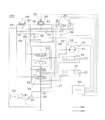
- FIG. 2 shows a hydraulic control device 100 of the wheeled hydraulic excavator 1 according to the embodiment.
- the hydraulic control apparatus 100 drives a traveling hydraulic motor 11 for driving the traveling body 2, a boom hydraulic cylinder 12 for driving the boom 4a, and an arm 4b.
- the arm hydraulic cylinder 13 is provided. Note that the illustration of the swing hydraulic motor for driving the swing body 3 and the bucket hydraulic cylinder for driving the bucket 4c is omitted for the sake of simplicity.
- the boom hydraulic cylinder 12, the arm hydraulic cylinder 13, and the bucket hydraulic cylinder may be collectively referred to as “working hydraulic actuator”.
- the output shaft of the traveling hydraulic motor 11 is connected to the transmission 14, and the output shaft of the transmission 14 is transmitted to the tire 2a via a power transmission mechanism (not shown) such as an accelerator shaft.
- a vehicle speed detection sensor 15 is installed on the output shaft of the traveling hydraulic motor 11.
- the transmission 14 is a two-stage speed reducer, and a reduction ratio is switched between a high speed stage and a low speed stage by switching a travel mode changeover switch (not shown) installed in the cab 3a. That is, when the travel mode changeover switch is switched to the slow speed mode side, the reduction ratio of the transmission 14 is switched from the high speed stage to the low speed stage, and when the travel mode changeover switch is switched to the normal travel mode side, the transmission The reduction ratio of 14 is switched from the low speed stage to the high speed stage.
- the hydraulic oil discharged from the main pump 20 is supplied to the traveling hydraulic motor 11 and the working hydraulic actuator via the main pipeline 21.
- the main pump 20 is a variable displacement hydraulic pump and is driven by a prime mover (engine) 22.
- the prime mover 22 also drives a pilot pump 23 that is a constant displacement hydraulic pump.
- a traveling direction control valve 24 for controlling the operation of the traveling hydraulic motor 11 is provided.
- a boom direction control valve 25 for controlling the operation of the boom hydraulic cylinder 12 is provided between the main pump 20 and the boom hydraulic cylinder 12.
- an arm direction control valve 26 that controls the operation of the arm hydraulic cylinder 13 is provided between the main pump 20 and the arm hydraulic cylinder 13.
- Each of these directional control valves 24, 25, and 26 is a hydraulic pilot type spool valve, and is operated pilot pressure output from the proportional solenoid valve unit for traveling operation 27, the boom operating device 28, and the arm operating device 29, respectively. Driven by.
- the travel operation proportional solenoid valve unit 27 is operated by stepping on a travel operation device such as an accelerator pedal (not shown) provided in the cab 3a.
- a travel operation device such as an accelerator pedal (not shown) provided in the cab 3a.
- a boom operation device 28 and an arm operation device 29 are also provided in the cab 3a.
- the boom operation device 28 includes an auto cruise switch 30 that is operated by an operator.
- the boom direction control valve 25, the arm direction control valve 26, and the bucket direction control valve (not shown) may be collectively referred to as a “working direction control valve”.
- the boom operation device 28, the arm operation device 29, and the bucket operation device (not shown) may be collectively referred to as a “work operation device”.
- Pilot pressure discharged from the pilot pump 23 is supplied to the traveling proportional solenoid valve unit 27, the boom operation device 28, and the arm operation device 29 via the supply line 31.
- the travel operation proportional solenoid valve unit 27, the boom operation device 28, and the arm operation device 29 generate pilot pressures according to the operation amount and the operation direction, and the travel direction control valve 24 and the boom direction control valve 25 are generated.
- the arm direction control valve 26 is switched.
- the proportional solenoid valve unit for traveling operation 27 and the hydraulic pilot section of the traveling direction control valve 24 are connected via pilot lines 32 and 33, and each pilot line 32 and 33 has a shuttle valve. Both ends of 34 are connected.
- the shuttle valve 34 selects a higher one of the pressure in the pilot pipe line 32 and the pressure in the pilot pipe line 33 and selects it as the pilot pressure for operating the directional control valve 24 for traveling. It is a valve.
- the pilot pressure selected by the shuttle valve 34 is detected by a travel operation amount pressure sensor 35.
- the boom operation device 28 and the hydraulic pilot section of the boom direction control valve 25 are connected via pilot pipe lines 41 and 42, and the pilot pipe lines 41 and 42 are connected to both ends of the shuttle valve 43. Is connected.
- the shuttle valve 43 selects a higher one of the pressure in the pilot pipe line 41 and the pressure in the pilot pipe line 42 and selects it as the pilot pressure for operating the boom direction control valve 25, which is a high-pressure priority type shuttle. It is a valve.
- the arm operating device 29 and the hydraulic pilot section of the arm directional control valve 26 are connected via pilot pipelines 51 and 52, and the pilot pipelines 51 and 52 are connected to both ends of the shuttle valve 53. Is connected.
- the shuttle valve 53 selects a higher one of the pressure in the pilot pipe line 51 and the pressure in the pilot pipe line 52 and selects it as the pilot pressure for operating the directional control valve 26 for the arm. It is a valve.
- the shuttle valve 43 and the shuttle valve 53 are connected via a pressure detection pipeline 54, and the pilot pressure selected by the shuttle valve 43 and the pilot pressure selected by the shuttle valve 53 are connected to the pressure detection pipeline 54.
- a high-pressure priority type shuttle valve 55 for selecting which one is higher is provided.
- the pilot pressure selected by the shuttle valve 55 is detected by the front operation amount pressure sensor 56.
- the output signal of the vehicle speed detection sensor 15, the output signal of the auto cruise switch 30, the output signal of the travel operation amount pressure sensor 35, and the output signal of the front operation amount pressure sensor 56 are input to the controller 60.
- the controller 60 controls the traveling state of the wheeled traveling body 2 based on these output signals.
- the working direction control valve including the traveling direction control valve 24, the boom direction control valve 25 and the arm direction control valve 26 is a tandem center type three-position valve, and the normal position of the valve position is set to the neutral position. ing.
- these directional control valves are configured to be able to selectively switch from the neutral position to the first switching position direction and the second switching position direction, and the valve position is changed from the neutral position to the first switching position direction or the second switching position direction.
- the flow direction and flow rate of the pressure oil supplied from the main pump 20 to each of the working hydraulic actuators including the traveling hydraulic motor 11, the boom hydraulic cylinder 12, and the arm hydraulic cylinder are To control.
- the traveling hydraulic motor 11 and the working hydraulic actuator are driven by the designated amount in the direction designated by operating the working operation device.
- the pressure oil discharged from the main pump 20 and passing through the traveling direction control valve 24 and the working direction control valve is returned to the hydraulic oil tank 16.
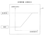
- the controller 60 shows the relationship between the amount of depression of the accelerator pedal and the proportional valve pressure when the auto cruise switch 30 is in the OFF state and the vehicle is operating alone (when the front composite operation is not performed).
- An operation amount-proportional valve pressure table 61 is stored.
- the horizontal operation axis represents the travel operation amount and the vertical axis represents the proportional valve pressure, and the accelerator pedal is operated from the non-operation state to the maximum operation amount.
- the change of the proportional valve pressure according to the operation amount of the accelerator pedal up to is stored as a characteristic diagram in a graph format.
- the controller 60 stores the actual vehicle speed at that time as the target vehicle speed. Further, the controller 60 operates the wheel-type traveling body 2 and the front work device 4 in a composite manner (hereinafter, this operation state is referred to as “front composite time”), and the auto-cruise switch 30 is turned on. In addition, the actual vehicle speed at that time is stored in the target vehicle speed at the time of the front combined. Furthermore, the target vehicle speed and the target vehicle speed of the front combined cooking can be changed using an external tool, an input device installed on the vehicle body, or the like.
- the operator changes the setting by using an external tool, an input device installed on the vehicle body, etc., so that the minimum speed of the wheeled hydraulic excavator 1 is combined with the wheeled traveling body 2 and the front working device 4.
- the vehicle speed can be set to a predetermined vehicle speed, for example, 1 to 2 km / h.
- the controller 60 determines the target of the auto cruise control according to the determination results of the auto cruise control condition determination unit 62, the target vehicle speed switching condition determination unit 63, and the target vehicle speed switching condition determination unit 63. And a target vehicle speed selection unit 64 that switches the vehicle speed to the target vehicle speed at the time of front compounding or the vehicle speed of the wheeled hydraulic excavator 1 when the auto cruise switch 30 is turned on.
- the auto-cruise control condition determination unit 62 determines whether there is no travel operation signal from the travel operation amount pressure sensor 35, the auto-cruise switch 30 is in an off state, or a wheel-type hydraulic excavator when the prime mover 22 is activated.
- a predetermined speed for example, Vf ⁇ 0.3 Km / h
- the controller 60 does not perform the auto-cruise control of the wheeled hydraulic excavator 1 but controls the proportional solenoid valve unit for traveling operation 27 according to the accelerator operation.
- the auto-cruise control condition determination unit 62 receives a signal indicating that the wheel-type traveling body 2 is traveling from the traveling operation amount pressure sensor 35 in a state where the prime mover 22 is activated,
- the auto cruise switch 30 When the auto cruise switch 30 is on and the actual speed of the wheeled hydraulic excavator 1 is equal to or higher than a predetermined speed, for example, Va ⁇ 8 Km / h, the auto cruise control condition is “b”.
- the controller 60 controls the proportional solenoid valve unit for traveling operation 27 so that the wheeled hydraulic excavator 1 travels automatically.
- the target vehicle speed switching condition determination unit 63 determines that the automatic cruise control condition determination unit 62 determines that the automatic cruise control condition is “b”, and receives a signal indicating the operation of the front work device 4 from the front operation amount pressure sensor 56. When there is no input, it is determined that the target vehicle speed switching condition is “a”, and the target speed of the wheeled hydraulic excavator 1 is set to the speed when the auto-cruise switch 30 is turned on. As a result, the wheel-type hydraulic excavator 1 can perform auto-cruise traveling at a vehicle speed of 8 km / h or more and a maximum vehicle speed or less. Therefore, it is possible to run an auto cruise on a general road.
- the target vehicle speed switching condition determination unit 63 determines that the auto cruise control condition is “b” by the auto cruise control condition determination unit 62, and the front operation amount pressure sensor 56 determines the front work device 4.
- the target vehicle speed switching condition is “b”
- the target speed of the wheeled hydraulic excavator 1 is determined as the target vehicle speed at the time of front combination.
- the wheel-type hydraulic excavator 1 is automatically decelerated from a state where the vehicle is traveling at a vehicle speed of 8 km / h or more and below the maximum vehicle speed to a vehicle speed at which a front combined operation of about 1 to 2 km / h is possible.
- Autocruise is run at a vehicle speed that allows multiple operations.
- the automatic cruise control device of the wheeled hydraulic excavator 1 can set the vehicle speed of the automatic cruise traveling at the time of the front combined operation to a vehicle speed that can always perform the combined front operation. Efficiency can be increased.
- the target speed selected by the target vehicle speed selection unit 64 is input to the subtractor 66 via the low-pass filter 65, and the deviation from the actual vehicle speed detected by the vehicle speed detection sensor 15 is calculated. Further, based on the vehicle speed deviation calculated by the subtractor 66, the correction pressure of the travel operation amount pressure sensor 35 is calculated by the vehicle speed deviation-correction pressure calculator 67, and the drive of the travel operation proportional solenoid valve unit 27 is controlled. Is done.
- the automatic cruise control device of the wheeled hydraulic excavator 1 inputs the target speed selected by the target vehicle speed selection unit 64 to the subtractor 66 via the low-pass filter 65, the actual vehicle speed and the target vehicle speed are calculated. Even when the difference is large, the speed change of the wheeled hydraulic excavator 1 can be made gradual, and the discomfort given to the operator can be alleviated.
- step S1 When the auto cruise control condition determining unit 62 determines that the auto cruise control condition is “b” in a state in which the wheel type traveling body 2 is capable of traveling (Yes in step S1), the controller 60 performs the wheel excavator 1
- the auto-cruise control is started at the vehicle speed when the auto-cruise switch 30 is turned on (step S2). If it is determined No in step S1, the automatic cruise control is terminated and the wheeled hydraulic excavator 1 is driven at a vehicle speed corresponding to the amount of depression of the accelerator pedal.
- step S3 If it is determined No in step S3 and the front work device 4 is operated (Yes in step S4), the auto-cruise control is started at the vehicle speed at the time of the front combination (step S5). If it is determined No in step S4, the process returns to step S3, and steps S3 and S4 are repeated.
- step S6 the process proceeds to step S7, and it is determined whether or not the driving of the front work device 4 is continued within a predetermined time, for example, within 2 to 3 seconds. If it is determined in step S7 that the driving of the front working device 4 is continued (Yes in step S7), the process returns to step S5 and the auto-cruise control at the vehicle speed at the time of front combination is continued. If it is determined in step S7 that the driving of the front work device 4 has been interrupted (No in step S7), the process returns to step S3 to auto-cruise at the vehicle speed when the auto-cruise switch 30 is turned on. Control.
- the front work device 4 when performing an operation of leveling the ground of a green zone provided on the side of the road with the bucket 4c, the front work device 4 while the cruise of the wheeled hydraulic excavator 1 is automatically cruise controlled at the vehicle speed at the time of the front combined.
- the front working device 4 can be performed without performing the switching operation of the auto-cruise switch 30, so that the operation of the wheel-type hydraulic excavator 1 can be performed. Can be improved.
- the automatic cruise control device of the wheeled hydraulic excavator 1 has been described as an example, but the present invention can be applied to a hydraulic control device of a wheeled work machine other than the wheeled hydraulic excavator.
- the auto-cruise control 30 is turned on / off by turning on / off the auto-cruise switch 30, but the gist of the present invention is not limited to this, and the driver's cab is not limited thereto. It is also possible to adopt a configuration in which the auto-cruise control is started at the vehicle speed at the time of front combined by switching the transmission 14 to a low speed stage by a travel mode changeover switch (not shown) installed in 3a. In this case, the travel mode changeover switch functions as an auto-cruise selection unit, similar to the auto-cruise switch 30.
Abstract
作業内容に合わせてオートクルーズ走行の維持速度を設定可能な作業車両を提供する。 走行操作量用圧力センサ(35)の出力信号、オートクルーズスイッチ(30)の出力信号及びホイール式油圧ショベル(1)の実車速に基づいてホイール式油圧ショベル(1)のオートクルーズ制御条件を判断するオートクルーズ制御条件判断部(62)と、オートクルーズ制御条件判断部(62)の判断内容及びフロント操作量用圧力センサ(56)からの入力信号に基づいて目標車速切替条件を判断する目標車速切替条件判断部(63)と、ホイール式油圧ショベルの実車速とフロント複合時の目標車速の偏差をゼロにする方向に走行操作量用圧力センサ(35)の補正圧力を求める車速偏差-補正圧力算出器(67)とを備える。
Description
本発明は、ホイール式作業機械等の作業車両に関する。
従来、オペレータによるオートクルーズ走行モードの選択に応じて作業車両を予め設定された一定速度で自動走行させる、オートクルーズ制御部を備えた作業車両が知られている(例えば、特許文献1参照。)。
特許文献1に記載された従来の作業車両は、オペレータがオートクルーズ走行モードを選択したときの走行モードが通常走行モードである場合には、予め設定された通常モードテーブルの最大車速をオートクルーズ走行の維持速度として決定する。また、オペレータがオートクルーズ走行モードを選択したときの走行モードが作業走行モードである場合には、予め設定された作業モードテーブルの最大車速をオートクルーズ走行の維持速度として決定する。作業モードテーブルの最大車速は、オペレータが作業車両に備えられた速度上限ダイヤルスイッチを操作することにより設定される。
なお、通常走行モードとは、一般道を走行可能な作業車両の走行モードであり、作業走行モードとは、何らかの作業を行う際の作業車両の走行モードである。作業走行モードにおける作業車両の最大車速は、通常走行モードにおける作業車両の最大車速よりも低速に設定される。
従来の作業車両は、このように構成されているので、一般道を走行可能な高速度でオートクルーズ走行することもできるし、何らかの作業を行うことが可能な低速度でもオートクルーズ走行することもできる。
しかしながら、従来の作業車両は、作業走行モードで走行中にオペレータがオートクルーズ走行モードを選択したとき、オートクルーズ走行の維持速度が、予め設定された作業モードテーブルに基づいて自動的に決定されるので、実行しようとする作業に作業車両の走行速度が適合しない場合がある。
この場合、オペレータは、オートクルーズ走行を解除した上で、速度上限ダイヤルスイッチを操作して作業モードテーブルの最大車速の設定をやり直し、しかる後に、再度作業車両を作業走行モードで走行させてオートクルーズ走行モードを選択する、という作業を行わなくてはならず、作業車両の稼働効率が悪いものとなる。
本発明は、このような従来技術の実情を考慮してなされたものであり、その目的は、作業内容に合わせてオートクルーズ走行の維持速度を設定可能な作業車両を提供することにある。
本発明は、前記課題を解決するため、車体と、前記車体の下方に設けられた車輪と、前記車体に対し上下方向に回動可能に取り付けられたフロント作業装置と、前記車体上に搭載されたエンジンと、前記エンジンにより駆動される油圧ポンプと、前記油圧ポンプから吐出される圧油により伸縮され、前記フロント作業装置を動作させる油圧シリンダと、前記油圧ポンプから吐出される圧油により駆動し前記車輪を回転させる走行モータと、前記走行モータの回転数に基づき車速を検出する車速センサと、前記油圧シリンダを操作する操作レバーと、前記走行モータを操作量に基づき操作する操作ペダルと、前記車速を第1の速度に維持するオートクルーズ機能を有効もしくは無効に切換える指示装置と、を備えた作業車両において、前記指示装置により前記オートクルーズ機能が有効に切換え操作され、かつ、前記走行モータが駆動されている状態で、前記操作レバーが操作されたとき、前記車速を、前記第1の速度から、前記第1の速度に比べて遅い第2の速度に変更し、その速度を維持する制御を行う制御装置を備えたことを特徴とする。
本発明によれば、実行しようとする作業に合わせてオートクルーズ走行の維持速度を設定することができ、作業車両の稼働効率を改善できる。なお、上述した以外の課題、構成及び効果については、以下に記載する実施形態の説明により明らかにされる。
以下、本発明に係る作業車両の実施形態を、ホイール式油圧ショベルを例にとり、図を参照しながら説明する。
図1に示すように、実施形態に係るホイール式油圧ショベル1は、タイヤ2aを備えた4輪構造のホイール式走行体2を備えている。また、ホイール式走行体2上には、運転室3a等を有する旋回体3が旋回可能に設けられている。更に、旋回体3の前部には、ブーム4a、アーム4b及びバケット4cからなる3節リンク構造のフロント作業装置4が設けられている。
ホイール式走行体2、旋回体3、ブーム4a、アーム4b及びバケット4cは、油圧ポンプから吐出される圧油により駆動される。図2に、実施形態に係るホイール式油圧ショベル1の油圧制御装置100を示す。
図2に示すように、実施形態に係る油圧制御装置100は、走行体2を駆動するための走行用油圧モータ11、ブーム4aを駆動するためのブーム用油圧シリンダ12及びアーム4bを駆動するためのアーム用油圧シリンダ13を備えている。なお、旋回体3を駆動するための旋回用油圧モータと、バケット4cを駆動するためのバケット用油圧シリンダについては、説明を簡略化するために図示を省略している。本明細書においては、ブーム用油圧シリンダ12、アーム用油圧シリンダ13及び図示しないバケット用油圧シリンダを総称して「作業用油圧アクチュエータ」と言うことがある。
走行用油圧モータ11の出力軸は、トランスミッション14に接続されており、トランスミッション14の出力軸は、アクセルシャフト等の図示しない動力伝達機構を介してタイヤ2aに伝達されている。また、走行用油圧モータ11の出力軸には、車速検出センサ15が設置されている。
トランスミッション14は、2段変速式の減速装置であり、運転室3a内に設置された図示しない走行モード切換スイッチを切り換えることによって、減速比が高速段及び低速段に切り換えられる。即ち、走行モード切換スイッチが微速モード側に切り換えられた場合には、トランスミッション14の減速比を高速段から低速段に切り換え、走行モード切換スイッチが通常走行モード側に切り換えられた場合には、トランスミッション14の減速比を低速段から高速段に切り換える。
走行用油圧モータ11及び作業用油圧アクチュエータには、メインポンプ20から吐出された圧油がメイン管路21を介して供給される。メインポンプ20は、可変容量型油圧ポンプであり、原動機(エンジン)22により駆動される。また、原動機22は、定容量形油圧ポンプからなるパイロットポンプ23も駆動している。
メインポンプ20と走行用油圧モータ11との間には、走行用油圧モータ11の動作を制御する走行用方向制御弁24が設けられている。また、メインポンプ20とブーム用油圧シリンダ12との間には、ブーム用油圧シリンダ12の動作を制御するブーム用方向制御弁25が設けられている。更に、メインポンプ20とアーム用油圧シリンダ13との間には、アーム用油圧シリンダ13の動作を制御するアーム用方向制御弁26が設けられている。これらの各方向制御弁24、25、26は、油圧パイロット式のスプール弁であり、それぞれ走行操作用比例電磁弁ユニット27、ブーム用操作装置28及びアーム用操作装置29から出力される操作パイロット圧力によって駆動される。
なお、走行操作用比例電磁弁ユニット27は、運転室3aに備えられた図示しないアクセルペダル等の走行用操作装置を踏み込むことによって操作される。また、ブーム用操作装置28及びアーム用操作装置29も運転室3a内に備えられる。ブーム用操作装置28には、オペレータによって操作されるオートクルーズスイッチ30が備えられる。
本明細書においては、ブーム用方向制御弁25、アーム用方向制御弁26及び図示しないバケット用方向制御弁を総称して「作業用方向制御弁」と言うことがある。また、本明細書においては、ブーム用操作装置28、アーム用操作装置29及び図示しないバケット操作装置を総称して「作業用操作装置」と言うことがある。
走行操作用比例電磁弁ユニット27、ブーム用操作装置28及びアーム用操作装置29には、パイロットポンプ23から吐出されたパイロット圧が供給管路31を介して供給される。走行操作用比例電磁弁ユニット27、ブーム用操作装置28及びアーム用操作装置29は、その操作量及び操作方向に応じたパイロット圧を生成し、走行用方向制御弁24、ブーム用方向制御弁25及びアーム用方向制御弁26の切り換えを行う。
即ち、走行操作用比例電磁弁ユニット27と走行用方向制御弁24の油圧パイロット部とは、パイロット管路32、33を介して接続されており、各パイロット管路32、33には、シャトル弁34の両端が接続されている。シャトル弁34は、パイロット管路32内の圧力とパイロット管路33内の圧力のうち、いずれか高い方を選択して走行用方向制御弁24を操作するパイロット圧として選択する高圧優先形のシャトル弁である。シャトル弁34により選択されたパイロット圧は、走行操作量用圧力センサ35により検出される。
また、ブーム用操作装置28とブーム用方向制御弁25の油圧パイロット部とは、パイロット管路41、42を介して接続されており、各パイロット管路41、42には、シャトル弁43の両端が接続されている。シャトル弁43は、パイロット管路41内の圧力とパイロット管路42内の圧力のうち、いずれか高い方を選択してブーム用方向制御弁25を操作するパイロット圧として選択する高圧優先形のシャトル弁である。
また、アーム用操作装置29とアーム用方向制御弁26の油圧パイロット部とは、パイロット管路51、52を介して接続されており、各パイロット管路51、52には、シャトル弁53の両端が接続されている。シャトル弁53は、パイロット管路51内の圧力とパイロット管路52内の圧力のうち、いずれか高い方を選択してアーム用方向制御弁26を操作するパイロット圧として選択する高圧優先形のシャトル弁である。
シャトル弁43とシャトル弁53とは、圧力検出管路54を介して接続されており、この圧力検出管路54には、シャトル弁43が選択したパイロット圧とシャトル弁53が選択したパイロット圧とのうち、いずれか高い方を選択する高圧優先形のシャトル弁55が備えられている。シャトル弁55により選択されたパイロット圧は、フロント操作量用圧力センサ56により検出される。
車速検出センサ15の出力信号、オートクルーズスイッチ30の出力信号、走行操作量用圧力センサ35の出力信号及びフロント操作量用圧力センサ56の出力信号は、コントローラ60に入力される。コントローラ60は、これらの各出力信号に基づいてホイール式走行体2の走行状態を制御する。
走行用方向制御弁24並びにブーム用方向制御弁25及びアーム用方向制御弁26を含む作業用方向制御弁は、タンデムセンタ形の3位置弁であり、弁位置のノーマル位置は中立位置に設定されている。
また、これらの方向制御弁は、中立位置から第1切替位置方向及び第2切替位置方向に選択的に切替できるように構成されており、弁位置を中立位置から第1切替位置方向又は第2切替位置方向に操作することにより、メインポンプ20から走行用油圧モータ11並びにブーム用油圧シリンダ12及びアーム用油圧シリンダを含む作業用油圧アクチュエータのそれぞれに供給される圧油の流れの方向と流量とを制御する。これにより、走行用油圧モータ11及び作業用油圧アクチュエータが、作業用操作装置を操作することにより指示された方向に、指示された量だけ駆動される。
メインポンプ20から吐出され、走行用方向制御弁24及び作業用方向制御弁を通過した圧油は、作動油タンク16に戻される。
以下、実施形態に係るコントローラ60の構成及び動作を、図3~図5を用いて説明する。
図3に示すように、コントローラ60は、オートクルーズスイッチ30がオフ状態であって走行単独操作時(フロント複合操作されていないとき)のアクセルペダルの踏み込み量と比例弁圧力との関係を示す走行操作量-比例弁圧力テーブル61を記憶している。走行操作量-比例弁圧力テーブル61は、図4に拡大して示すように、横軸に走行操作量、縦軸に比例弁圧力とし、アクセルペダルが非操作状態から最大操作量まで操作されるまでのアクセルペダルの操作量に応じた比例弁圧力の変化が、特性線図としてグラフ形式で記憶されている。
一方で、図3に示すように、コントローラ60は、ホイール式走行体2を単独で操作し、かつオートクルーズスイッチ30をオン操作したときに、そのときの実車速を目標車速として記憶する。また、コントローラ60は、ホイール式走行体2とフロント作業装置4とを複合的に操作し(以下、この操作状態を「フロント複合時」という。)、かつ、オートクルーズスイッチ30をオン操作したときに、そのときの実車速をフロント複合時の目標車速に記憶するようにしている。さらに、これらの目標車速、及びフロント複合煮の目標車速は、外部ツールや車体に設置された入力装置等を用いて設定を変更することができる。
一方で、図3に示すように、コントローラ60は、ホイール式走行体2を単独で操作し、かつオートクルーズスイッチ30をオン操作したときに、そのときの実車速を目標車速として記憶する。また、コントローラ60は、ホイール式走行体2とフロント作業装置4とを複合的に操作し(以下、この操作状態を「フロント複合時」という。)、かつ、オートクルーズスイッチ30をオン操作したときに、そのときの実車速をフロント複合時の目標車速に記憶するようにしている。さらに、これらの目標車速、及びフロント複合煮の目標車速は、外部ツールや車体に設置された入力装置等を用いて設定を変更することができる。
したがって、オペレータは、外部ツールや車体に設置された入力装置等を用いて設定を変更することにより、ホイール式油圧ショベル1の最低速度を、ホイール式走行体2とフロント作業装置4とを複合的に操作可能な所定の車速、例えば1~2Km/hに設定できる。
また、コントローラ60は、図3に示すように、オートクルーズ制御条件判断部62と、目標車速切替条件判断部63と、目標車速切替条件判断部63の判断結果に応じて、オートクルーズ制御の目標車速を、フロント複合時の目標車速又はオートクルーズスイッチ30をオン操作したときのホイール式油圧ショベル1の車速に切り換える目標車速選択部64とを有している。
オートクルーズ制御条件判断部62は、原動機22が起動されている状態において、走行操作量用圧力センサ35からの走行操作信号がないか、オートクルーズスイッチ30がオフ状態であるか、ホイール式油圧ショベル1の実速度が予め定められた所定速度以下、例えばVf≦0.3Km/hである場合には、オートクルーズ制御条件は「a」であると判断する。このとき、コントローラ60は、ホイール式油圧ショベル1のオートクルーズ制御を行わず、アクセル操作に応じて走行操作用比例電磁弁ユニット27を制御する。
これに対して、オートクルーズ制御条件判断部62は、原動機22が起動されている状態において、走行操作量用圧力センサ35からホイール式走行体2が走行中であることを示す信号が入力され、オートクルーズスイッチ30がオン状態であり、かつホイール式油圧ショベル1の実速度が予め定められた所定速度以上、例えばVa≧8Km/hである場合には、オートクルーズ制御条件は「b」であると判断する。このとき、コントローラ60は、ホイール式油圧ショベル1をオートクルーズ走行させるように走行操作用比例電磁弁ユニット27を制御する。
目標車速切替条件判断部63は、オートクルーズ制御条件判断部62によってオートクルーズ制御条件は「b」であると判断され、かつフロント操作量用圧力センサ56からフロント作業装置4の操作を示す信号の入力がない場合、目標車速切替条件は「a」であると判断して、ホイール式油圧ショベル1の目標速度をオートクルーズスイッチ30がオン操作されたときの速度に定める。これにより、ホイール式油圧ショベル1は、8Km/h以上最大車速以下の車速でオートクルーズ走行が可能になる。よって、一般道におけるオートクルーズ走行も可能になる。
これに対して、目標車速切替条件判断部63は、オートクルーズ制御条件判断部62によってオートクルーズ制御条件は「b」であると判断され、かつフロント操作量用圧力センサ56からフロント作業装置4の操作を示す信号が入力した場合、目標車速切替条件は「b」であると判断して、ホイール式油圧ショベル1の目標速度を、フロント複合時の目標車速に定める。これにより、ホイール式油圧ショベル1は、8Km/h以上最大車速以下の車速で走行している状態から、1~2Km/h程度のフロント複合操作が可能な車速に自動的に減速され、そのフロント複合操作が可能な車速でオートクルーズ走行される。
よって、実施形態に係るホイール式油圧ショベル1のオートクルーズ制御装置は、フロント複合時におけるオートクルーズ走行の車速を、常にフロント複合作業が可能な車速にすることができ、ホイール式油圧ショベル1の作業効率を高めることができる。
なお、目標車速選択部64で選択された目標速度は、ローパスフィルタ65を介して減算器66に入力され、車速検出センサ15で検出された実車速との偏差が算出される。また、減算器66によって算出された車速偏差に基づいて、走行操作量用圧力センサ35の補正圧力が車速偏差-補正圧力算出器67で算出され、走行操作用比例電磁弁ユニット27の駆動が制御される。
実施形態に係るホイール式油圧ショベル1のオートクルーズ制御装置は、目標車速選択部64で選択された目標速度を、ローパスフィルタ65を介して減算器66に入力するので、実車速と目標車速との差が大きい場合にも、ホイール式油圧ショベル1の速度変化を緩やかなものにすることができ、オペレータに与える不快感を緩和することができる。
以下、図5に示すフローチャートを用いて、実施形態に係るオートクルーズ制御装置の動作を詳細に説明する。
ホイール式走行体2が走行可能な状態で、オートクルーズ制御条件判断部62がオートクルーズ制御条件は「b」であると判断したとき(ステップS1でYes)、コントローラ60は、ホイール式油圧ショベル1をオートクルーズスイッチ30がオン操作されたときの車速でオートクルーズ制御を開始する(ステップS2)。ステップS1でNoと判断した場合は、オートクルーズ制御を終了し、ホイール式油圧ショベル1をアクセルペダルの踏み込み量に応じた車速で走行させる。
ホイール式油圧ショベル1が、オートクルーズスイッチ30がオン操作されたときの車速でオートクルーズ制御されている状態で、図示しないブレーキが操作されるか、オートクルーズスイッチ30がオフ操作されるか、車速がVf以下になった場合にも(ステップS3でYes)、オートクルーズ制御を終了する。
ステップS3でNoと判断した場合であって、フロント作業装置4の操作が行われた場合には(ステップS4でYes)、フロント複合時の車速でオートクルーズ制御を開始する(ステップS5)。ステップS4でNoと判断した場合は、ステップS3に戻って、ステップS3及びステップS4を繰り返す。
フロント複合時の車速でオートクルーズ制御を開始した状態で、図示しないブレーキが操作されるか、オートクルーズスイッチ30がオフ操作されるか、車速がVf以下になった場合にも(ステップS6でYes)、オートクルーズ制御を終了する。
ステップS6でNoと判断した場合は、ステップS7に移行し、所定時間、例えば2~3秒以内にフロント作業装置4の駆動が継続されているか否かについて判断する。ステップS7でフロント作業装置4の駆動が継続されていると判断した場合は(ステップS7でYes)、ステップS5に戻ってフロント複合時の車速でのオートクルーズ制御を継続する。ステップS7でフロント作業装置4の駆動が中断されたと判断した場合は(ステップS7でNo)、ステップS3に戻ってホイール式油圧ショベル1をオートクルーズスイッチ30がオン操作されたときの車速でオートクルーズ制御する。
これにより、例えば道路脇に設けられた緑地帯の地面をバケット4cで均す作業を行う場合に、ホイール式油圧ショベル1の走行をフロント複合時の車速でオートクルーズ制御しながら、フロント作業装置4を駆動して、道路脇に設けられた緑地帯の地面をバケット4cで均す作業と、次の緑地帯に到着するまでの間、フロント作業装置4の駆動を停止して、ホイール式油圧ショベル1の走行をオートクルーズスイッチ30がオン操作されたときの車速でオートクルーズ走行させる作業とを、オートクルーズスイッチ30の切換操作を行うことなく行うことができるので、ホイール式油圧ショベル1の作業効率を良好なものにできる。
なお、上述の実施形態は、本発明を説明するための例示であり、本発明の範囲を上述の実施形態にのみ限定する趣旨ではない。当業者は、本発明の要旨を逸脱することなしに、他の様々な態様で本発明を実施することができる。
例えば、上述の実施形態では、ホイール式油圧ショベル1のオートクルーズ制御装置を例にとって説明したが、ホイール式油圧ショベル以外のホイール式作業機械の油圧制御装置に適用することができる。
また、上述の実施形態では、オートクルーズスイッチ30をオン・オフ操作することによってオートクルーズ制御のオン・オフを切り換える構成としたが、本発明の要旨はこれに限定されるものではなく、運転室3a内に設置された図示しない走行モード切換スイッチによりトランスミッション14を低速段に切り換えることによって、フロント複合時の車速でオートクルーズ制御を開始する構成とすることもできる。この場合、走行モード切換スイッチは、オートクルーズスイッチ30と同様に、オートクルーズ選択部として機能する。
1 ホイール式油圧ショベル
2 ホイール式走行体
3 旋回体
4 フロント作業装置
5 原動機
27 走行操作用比例電磁弁ユニット
28 ブーム用操作装置
29 アーム用操作装置
30 オートクルーズスイッチ
35 走行操作量用圧力センサ
56 フロント操作量用圧力センサ
60 コントローラ
61 走行操作量-比例弁圧力テーブル
62 オートクルーズ制御条件判断部
63 目標車速切替条件判断部
64 目標車速選択部
65 ローパスフィルタ
66 減算器
67 車速偏差-補正圧力器
2 ホイール式走行体
3 旋回体
4 フロント作業装置
5 原動機
27 走行操作用比例電磁弁ユニット
28 ブーム用操作装置
29 アーム用操作装置
30 オートクルーズスイッチ
35 走行操作量用圧力センサ
56 フロント操作量用圧力センサ
60 コントローラ
61 走行操作量-比例弁圧力テーブル
62 オートクルーズ制御条件判断部
63 目標車速切替条件判断部
64 目標車速選択部
65 ローパスフィルタ
66 減算器
67 車速偏差-補正圧力器
Claims (2)
- 車体と、
前記車体の下方に設けられた車輪と、
前記車体に対し上下方向に回動可能に取り付けられたフロント作業装置と、
前記車体上に搭載されたエンジンと、
前記エンジンにより駆動される油圧ポンプと、
前記油圧ポンプから吐出される圧油により伸縮され、前記フロント作業装置を動作させる油圧シリンダと、
前記油圧ポンプから吐出される圧油により駆動し前記車輪を回転させる走行モータと、
前記走行モータの回転数に基づき車速を検出する車速センサと、
前記油圧シリンダを操作する操作レバーと、
前記走行モータを操作量に基づき操作する操作ペダルと、
前記車速を第1の速度に維持するオートクルーズ機能を有効もしくは無効に切換える指示装置と、
を備えた作業車両において、
前記指示装置により前記オートクルーズ機能が有効に切換え操作され、かつ、前記走行モータが駆動されている状態で、前記操作レバーが操作されたとき、
前記車速を、前記第1の速度から、前記第1の速度に比べて遅い第2の速度に変更し、その速度を維持する制御を行う制御装置を
備えたことを特徴とする作業車両。 - 請求項1に記載の作業車両において、
前記制御装置は、
前記指示装置により前記オートクルーズ機能が有効に切換え操作され、かつ、前記走行モータが駆動されている状態で、前記操作レバーが操作されたときを基準とした時間から予め設定された所定時間の間、前記操作レバーの非操作状態が続いた場合には、
前記車速を前記第1の速度に変更することを特徴とする作業車両。
Priority Applications (5)
| Application Number | Priority Date | Filing Date | Title |
|---|---|---|---|
| JP2018545263A JP6648296B2 (ja) | 2017-03-28 | 2017-03-28 | 作業車両 |
| EP17898336.7A EP3421845B1 (en) | 2017-03-28 | 2017-03-28 | Work vehicle |
| KR1020187024434A KR102081294B1 (ko) | 2017-03-28 | 2017-03-28 | 작업 차량 |
| CN201780013736.4A CN109073075B (zh) | 2017-03-28 | 2017-03-28 | 作业车辆 |
| PCT/JP2017/012763 WO2018179113A1 (ja) | 2017-03-28 | 2017-03-28 | 作業車両 |
Applications Claiming Priority (1)
| Application Number | Priority Date | Filing Date | Title |
|---|---|---|---|
| PCT/JP2017/012763 WO2018179113A1 (ja) | 2017-03-28 | 2017-03-28 | 作業車両 |
Publications (1)
| Publication Number | Publication Date |
|---|---|
| WO2018179113A1 true WO2018179113A1 (ja) | 2018-10-04 |
Family
ID=63677397
Family Applications (1)
| Application Number | Title | Priority Date | Filing Date |
|---|---|---|---|
| PCT/JP2017/012763 WO2018179113A1 (ja) | 2017-03-28 | 2017-03-28 | 作業車両 |
Country Status (5)
| Country | Link |
|---|---|
| EP (1) | EP3421845B1 (ja) |
| JP (1) | JP6648296B2 (ja) |
| KR (1) | KR102081294B1 (ja) |
| CN (1) | CN109073075B (ja) |
| WO (1) | WO2018179113A1 (ja) |
Families Citing this family (1)
| Publication number | Priority date | Publication date | Assignee | Title |
|---|---|---|---|---|
| CN111663600B (zh) * | 2020-06-08 | 2022-11-11 | 雷沃工程机械集团有限公司 | 一种挖掘机自动巡航方法及系统 |
Citations (5)
| Publication number | Priority date | Publication date | Assignee | Title |
|---|---|---|---|---|
| JP2008082030A (ja) * | 2006-09-27 | 2008-04-10 | Hitachi Constr Mach Co Ltd | 建設機械の操作系制御装置 |
| JP2012067829A (ja) | 2010-09-22 | 2012-04-05 | Iseki & Co Ltd | 作業車両 |
| JP2012188861A (ja) * | 2011-03-10 | 2012-10-04 | Yanmar Co Ltd | 作業車両 |
| JP2016008655A (ja) * | 2014-06-24 | 2016-01-18 | 井関農機株式会社 | 作業車両 |
| JP2016098985A (ja) * | 2014-11-26 | 2016-05-30 | 井関農機株式会社 | 作業車両 |
Family Cites Families (7)
| Publication number | Priority date | Publication date | Assignee | Title |
|---|---|---|---|---|
| JP2007170131A (ja) * | 2005-12-26 | 2007-07-05 | Iseki & Co Ltd | トラクタのフロントローダ |
| SE530806C2 (sv) * | 2007-01-30 | 2008-09-16 | Scania Cv Abp | Förfarande för reglering av målhastigheten hos ett farthållarsystem, och farthållarsystem |
| US8121763B2 (en) * | 2008-12-08 | 2012-02-21 | Cnh America Llc | Automatic productivity management control with standard power shift transmission |
| JP2013227799A (ja) * | 2012-04-26 | 2013-11-07 | Iseki & Co Ltd | フロントローダ作業車の変速制御装置 |
| CA2906024C (en) * | 2014-09-24 | 2022-07-26 | Eric Amback | Low speed cruise control for a vehicle |
| WO2017036492A1 (en) * | 2015-08-28 | 2017-03-09 | Volvo Truck Corporation | A method and a system for controlling vehicle speed |
| CN105114588B (zh) * | 2015-08-31 | 2017-05-03 | 北京理工大学 | 一种等比五段式液压机械复合无级传动装置 |
-
2017
- 2017-03-28 KR KR1020187024434A patent/KR102081294B1/ko active IP Right Grant
- 2017-03-28 CN CN201780013736.4A patent/CN109073075B/zh active Active
- 2017-03-28 EP EP17898336.7A patent/EP3421845B1/en active Active
- 2017-03-28 WO PCT/JP2017/012763 patent/WO2018179113A1/ja unknown
- 2017-03-28 JP JP2018545263A patent/JP6648296B2/ja active Active
Patent Citations (5)
| Publication number | Priority date | Publication date | Assignee | Title |
|---|---|---|---|---|
| JP2008082030A (ja) * | 2006-09-27 | 2008-04-10 | Hitachi Constr Mach Co Ltd | 建設機械の操作系制御装置 |
| JP2012067829A (ja) | 2010-09-22 | 2012-04-05 | Iseki & Co Ltd | 作業車両 |
| JP2012188861A (ja) * | 2011-03-10 | 2012-10-04 | Yanmar Co Ltd | 作業車両 |
| JP2016008655A (ja) * | 2014-06-24 | 2016-01-18 | 井関農機株式会社 | 作業車両 |
| JP2016098985A (ja) * | 2014-11-26 | 2016-05-30 | 井関農機株式会社 | 作業車両 |
Also Published As
| Publication number | Publication date |
|---|---|
| KR20180118637A (ko) | 2018-10-31 |
| JPWO2018179113A1 (ja) | 2019-04-04 |
| CN109073075A (zh) | 2018-12-21 |
| EP3421845B1 (en) | 2021-02-17 |
| EP3421845A4 (en) | 2020-01-15 |
| JP6648296B2 (ja) | 2020-02-14 |
| CN109073075B (zh) | 2020-06-19 |
| EP3421845A1 (en) | 2019-01-02 |
| KR102081294B1 (ko) | 2020-02-25 |
Similar Documents
| Publication | Publication Date | Title |
|---|---|---|
| EP1550803B1 (en) | Prime mover controller of construction machine | |
| JP5092060B1 (ja) | 作業車両及び作業車両の制御方法 | |
| WO2011027758A1 (ja) | 作業車両 | |
| WO2006098179A1 (ja) | 作業機械のhst走行システム | |
| CN111788360A (zh) | 作业车辆 | |
| JP5897492B2 (ja) | 作業機 | |
| JP4448777B2 (ja) | 静油圧式変速車両および静油圧式変速機のコントローラ | |
| WO2018179113A1 (ja) | 作業車両 | |
| US11352766B2 (en) | Working machine with a speed control arrangement | |
| JP5974029B2 (ja) | 作業機械の駆動装置 | |
| JP2572387B2 (ja) | ホイ−ル式油圧シヨベルの油圧制御装置 | |
| JP4589649B2 (ja) | ホイールローダのクラッチ制御装置およびホイールローダ | |
| WO2004029369A1 (ja) | 建設機械 | |
| JP4282871B2 (ja) | 油圧走行車両 | |
| JP5913175B2 (ja) | 作業機 | |
| JP6872478B2 (ja) | ホイール式作業車両 | |
| WO2020202652A1 (ja) | ホイール式作業車両 | |
| JP6581061B2 (ja) | ホイール式作業機械の油圧制御装置 | |
| JP2875571B2 (ja) | 油圧駆動車両の原動機制御装置 | |
| JP6180764B2 (ja) | 建設機械の油圧回路及びその制御方法 | |
| JPH0732240Y2 (ja) | 油圧駆動車両の走行速度制御装置 | |
| JP2744706B2 (ja) | 油圧駆動車両の走行速度制御装置 | |
| WO2016189634A1 (ja) | 作業機械の出力装置及び作業機械の出力方法 | |
| JP2006077427A (ja) | ホイール式油圧ショベル | |
| JP4713552B2 (ja) | 建設機械の走行制御装置 |
Legal Events
| Date | Code | Title | Description |
|---|---|---|---|
| ENP | Entry into the national phase |
Ref document number: 20187024434 Country of ref document: KR Kind code of ref document: A |
|
| ENP | Entry into the national phase |
Ref document number: 2018545263 Country of ref document: JP Kind code of ref document: A |
|
| 121 | Ep: the epo has been informed by wipo that ep was designated in this application |
Ref document number: 17898336 Country of ref document: EP Kind code of ref document: A1 |
|
| NENP | Non-entry into the national phase |
Ref country code: DE |