WO2018174055A1 - 燃料電池 - Google Patents
燃料電池 Download PDFInfo
- Publication number
- WO2018174055A1 WO2018174055A1 PCT/JP2018/011013 JP2018011013W WO2018174055A1 WO 2018174055 A1 WO2018174055 A1 WO 2018174055A1 JP 2018011013 W JP2018011013 W JP 2018011013W WO 2018174055 A1 WO2018174055 A1 WO 2018174055A1
- Authority
- WO
- WIPO (PCT)
- Prior art keywords
- flow path
- heat medium
- heat
- heating
- fuel cell
- Prior art date
- Legal status (The legal status is an assumption and is not a legal conclusion. Google has not performed a legal analysis and makes no representation as to the accuracy of the status listed.)
- Ceased
Links
Images

Classifications
-
- Y—GENERAL TAGGING OF NEW TECHNOLOGICAL DEVELOPMENTS; GENERAL TAGGING OF CROSS-SECTIONAL TECHNOLOGIES SPANNING OVER SEVERAL SECTIONS OF THE IPC; TECHNICAL SUBJECTS COVERED BY FORMER USPC CROSS-REFERENCE ART COLLECTIONS [XRACs] AND DIGESTS
- Y02—TECHNOLOGIES OR APPLICATIONS FOR MITIGATION OR ADAPTATION AGAINST CLIMATE CHANGE
- Y02E—REDUCTION OF GREENHOUSE GAS [GHG] EMISSIONS, RELATED TO ENERGY GENERATION, TRANSMISSION OR DISTRIBUTION
- Y02E60/00—Enabling technologies; Technologies with a potential or indirect contribution to GHG emissions mitigation
- Y02E60/30—Hydrogen technology
- Y02E60/50—Fuel cells
Definitions
- the present disclosure relates to a fuel cell that generates power by chemically reacting hydrogen and oxygen.
- the fuel cell includes a stack as a power generation unit that generates electricity by chemically reacting hydrogen and oxygen supplied from the outside, and a hydrogen supply unit that supplies hydrogen to the stack.
- the stack a plurality of stacked cells are packaged.
- the negative electrode, the solid polymer film, and the positive electrode are bonded and integrated, and sandwiched between conductive plates.
- the hydrogen supply unit for example, an MH (Metal Hydride) cylinder filled with a hydrogen storage alloy is used.
- the supply of hydrogen is performed by heating the MH cylinder.
- the heating of the MH cylinder is performed using, for example, a heat medium passage through which a heat medium such as water circulates (see Patent Document 1).
- the heat medium flow path is formed using piping, and heats the MH cylinder by conducting heat generated in power generation to the MH cylinder via the heat medium.
- the MH cylinder is heated by a heater (see Patent Document 2).
- the present disclosure has been made in view of such circumstances, and an object of the present disclosure is to provide a fuel cell capable of circulating a heat medium even when the heat medium flow path is blocked. It is to provide.
- a fuel cell is provided with a heat medium channel that performs heat exchange by circulation of a heat medium for a power generation unit that generates electricity by reacting hydrogen and oxygen, and the heat medium channel,
- a heater that heats the heat medium
- a heating unit that is provided in the heat medium flow path and heats the heated part
- the heat medium flow path branches upstream of the heating part, and is downstream of the heating part.
- a branch channel that joins the heat medium channel on the side.
- the branch flow path is such that the heat medium flow path branches on the upstream side of the heating unit and merges with the heat medium flow path on the downstream side. Even in the case where the heating unit in the path is clogged, the heat medium circulates by flowing through the branch channel. Therefore, even when the heat medium passage is blocked, the heat medium can be circulated.
- the heat medium can be circulated even when the heat medium flow path is clogged.
- FIG. 1 is a block diagram showing a schematic configuration of a fuel cell according to Embodiment 1.
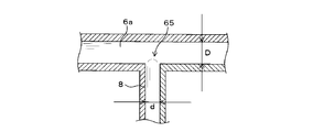
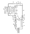
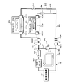
- FIG. It is a schematic diagram which shows the structure of piping in a 1st branch point. It is a schematic diagram explaining the flow of the heating liquid when obstruction
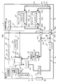
- 4 is a block diagram showing a schematic configuration of a fuel cell according to Embodiment 2.
- FIG. 1 is a block diagram showing a schematic configuration of a fuel cell according to Embodiment 1.
- FIG. 1 denotes a fuel cell, and the fuel cell 100 includes a battery body 1 and a hydrogen supply device 2.
- the battery body 1 includes a stack 10 that generates power using hydrogen and oxygen.
- the battery body 1 includes an air flow path 3 and an air pump 30.
- the air flow path 3 is formed so that air sent out by the operation of the air pump 30 flows through the stack 10 and is discharged to the outside of the battery body 1.
- a first air shut-off valve 31 is provided on the air inflow side of the stack 10
- a second air shut-off valve 32 is provided on the air outflow side of the stack 10.
- the hydrogen supply device 2 includes a plurality of MH units 20, 20,... (Two in the figure) for supplying hydrogen.
- Each MH unit 20 has an MH cylinder 20a that is filled with a hydrogen storage alloy and stores hydrogen.
- Each MH cylinder 20a is connected to a hydrogen supply path 2a described later in an exchangeable manner.
- the fuel cell 100 further includes a hydrogen supply path 2 a and is formed across the battery body 1 and the hydrogen supply device 2. Further, the battery main body 1 is formed with a hydrogen circulation path 2b connected to the hydrogen supply path 2a. In the hydrogen supply path 2a and the hydrogen circulation path 2b, the hydrogen delivered from each MH cylinder 20a flows into the hydrogen circulation path 2b through the hydrogen supply path 2a, and then flows into the stack 10 through the hydrogen circulation path 2b. It is formed to be supplied.
- the hydrogen supply path 2a includes a first hydrogen cutoff valve 21, a regulator 22, a pressure sensor 23, a second hydrogen cutoff valve 24, and a third hydrogen cutoff from the MH unit 20 side between the MH unit 20 and the hydrogen circulation path 2b.
- a valve 25 and a check valve 26 are provided.
- the first hydrogen cutoff valve 21 and the regulator 22 are provided on the hydrogen supply device 2 side, and the pressure sensor 23, the second hydrogen cutoff valve 24, the third hydrogen cutoff valve 25, and the check valve 26 are on the battery body 1 side. Is provided.
- a hydrogen circulation pump 27 and a gas-liquid separator 28 are provided in the hydrogen circulation path 2b.
- the hydrogen circulation path 2 b is formed so that the gas containing hydrogen sent from the hydrogen circulation pump 27 flows through the stack 10 and then returns to the hydrogen circulation pump 27 through the gas-liquid separator 28.
- the gas flowing through the hydrogen circulation path 2b contains impurities such as nitrogen and water.
- the hydrogen supply path 2 a joins the hydrogen circulation path 2 b between the hydrogen circulation pump 27 and the hydrogen inflow side to the stack 10.
- the gas-liquid separator 28 separates the gas and water flowing through the hydrogen circulation path 2b, and supplies the separated water to the outside of the battery body 1 via a discharge path provided with a discharge valve (not shown). Discharge regularly.
- the hydrogen circulation path 2b is provided with a discharge path that periodically discharges the internal gas, discharges impurities by discharging the gas, and maintains the hydrogen concentration in the hydrogen circulation path 2b at a constant level. This prevents a decrease in the hydrogen concentration in 2b.
- the fuel cell 100 further includes a cooling water flow path 4, a heat radiation liquid flow path 5 and a heating liquid flow path 6, a first heat exchanger 70 and a second heat exchanger 71, and a branch flow path 8.
- the cooling water channel 4 is provided with a cooling pump 40 and an ion exchange resin 43.
- the cooling water sent from the cooling pump 40 passes through the first heat exchanger 70, the second heat exchanger 71, the ion exchange resin 43, and the stack 10 in order, and returns to the cooling pump 40.
- a pipe is used to circulate.
- the cooling water functions as a heat medium, and the cooling water flow path 4 cools the stack 10 by circulating the cooling water.
- a conductivity meter 44 is provided between the stack 10 and the ion exchange resin 43, and the conductivity of the cooling water is measured.
- the heat dissipation liquid flow path 5 is provided with a heat dissipation pump 50 and a radiator 51.
- a fan 52 is provided in the vicinity of the radiator 51.
- the heat-radiating liquid flow path 5 is formed using, for example, piping so that the heat-dissipating liquid sent from the heat-dissipating pump 50 flows through the first heat exchanger 70 and then flows through the radiator 51 and returns to the heat-dissipating pump 50.
- the heat dissipation liquid is, for example, an antifreeze liquid containing ethylene glycol as a main component.
- the heat dissipation liquid exchanges heat with the cooling water in the first heat exchanger 70.
- the radiator 51 performs heat dissipation of the circulating heat dissipation liquid, and the fan 52 promotes heat dissipation by the radiator 51.
- the heating liquid flow path 6 is provided across the battery body 1 and the hydrogen supply device 2, and the heating liquid flow path 6 heats the MH cylinders 20a and 20a by circulation of the heating liquid.
- the heating liquid is, for example, an antifreeze liquid mainly composed of ethylene glycol.
- the heating liquid channel 6 includes a first channel 6 a provided on the battery body 1 side, a second channel 6 b provided on the hydrogen supply device 2 side, a first channel 6 a and a second channel 6 b. It is formed by two communicating flow paths 6c and 6d that communicate with each other.
- the upstream side of the first flow path 6a and the downstream side of the second flow path 6b communicate with each other through the communication flow path 6c, and the downstream side of the first flow path 6a and the upstream side of the second flow path 6b communicate with each other. It communicates with the road 6d. Accordingly, in the first flow path 6a, the second flow path 6b, and the communication flow paths 6c and 6d, the heat medium flowing through the first flow path 6a flows through the communication flow path 6d and passes through the second flow path 6b. After flowing, it is formed so as to flow through another communication channel 6c and return to the first channel 6a.
- the first flow path 6a is provided with a heat pump 60.
- the first flow path 6a is a communication flow path after the heating liquid sent from the heat pump 60 flows through the second heat exchanger 71. It is formed to flow into 6d.
- the first flow path 6 a is formed by a pipe connected through the heat pump 60 and the second heat exchanger 71.
- a heater 62 is provided on the suction side of the heat pump 60.
- the second channel 6b is branched into a plurality of individual channels 63, 63,... (Two in the figure) in the middle part.
- the individual flow paths 63 merge on the downstream side of the second flow path 6b.
- the second channel 6b including the individual channel 63 is formed by piping.
- a proximity portion 20b close to the MH cylinder 20a of each MH unit 20 is provided to heat the MH cylinder 20a.
- the corresponding MH cylinder 20a is heated by the heat released from the heating liquid flowing through the proximity portion 20b.
- the piping portion forming the proximity portion 20b is provided in the individual flow path 63 via the valved coupler 600 provided on each of the upstream side and the downstream side, and constitutes a part thereof.
- Each proximity part 20b is attached and detached as the corresponding MH cylinder 20a is attached and detached, and forms a part of the MH unit 20.
- the valve-equipped coupler 600 is formed by a plug and a socket that are detachably connected to each other, and the plug and the socket each incorporate a so-called automatic opening / closing valve.
- the valve opens when the plug and socket are connected, so that the heating fluid flows through the valved coupler 600.
- the valve closes when the plug and socket are separated. Therefore, even if the plug and the socket are separated, the heating liquid does not flow out to the outside in the heating liquid channel 6.
- a switching valve 64 is further provided on the upstream side of the proximity portion 20b. Each switching valve 64 opens and closes each individual flow path 63, and the individual flow path 63 to be used is switched by opening and closing the switching valve 64.
- the communication channels 6c and 6d are formed by piping.
- the communication flow path 6c is connected to the upstream side of the first flow path 6a via the coupler 601 with a valve, and is connected to the downstream side of the second flow path 6b via the coupler 602 with a valve.
- the communication flow path 6d is connected to the downstream side of the first flow path 6a via the coupler with valve 603, and is connected to the upstream side of the second flow path 6b via the coupler with valve 604.
- the valved couplers 601 to 604 have the same structure as the valved coupler 600.
- the first flow path 6 a of the heating liquid flow path 6 is provided with a first branch point 65 and a second branch point 66 to which the branch flow path 8 is connected.
- the first branch point 65 is provided between the valved coupler 601 and the heater 62.
- the second branch point 66 is provided between the valved coupler 603 and the second heat exchanger 71.
- the branch flow path 8 is formed by piping and communicates the first branch point 65 and the second branch point 66.
- a relief valve 80 is provided in the branch flow path 8.
- the relief valve 80 is opened when a pressure equal to or higher than the cracking pressure Pc is applied from the second branch point 66 side, and is closed when a pressure smaller than the cracking pressure Pc is applied.
- the cracking pressure Pc is larger than the pressure loss ⁇ P of the heat medium in the flow path from the second branch point 66 to the first branch point 65 including the second flow path 6b, and smaller than the maximum pressure Pmax of the output of the heating pump 60. Is set to a value.
- FIG. 2 is a schematic diagram showing the structure of the piping at the first branch point 65.
- the piping that forms the first flow path 6a and the branch flow path 8 is, for example, a circular pipe.
- the inner diameter of the pipe forming the first flow path 6a is D
- the inner diameter of the pipe forming the branch flow path 8 is d (d ⁇ D). Therefore, the cross-sectional area of the pipe that forms the first flow path 6 a of the heating liquid flow path 6 is larger than the cross-sectional area of the pipe that forms the branch flow path 8.
- the first heat exchanger 70 performs heat exchange between the cooling water in the cooling water channel 4 and the heat radiation in the heat radiation channel 5.
- the second heat exchanger 71 performs heat exchange between the cooling water in the cooling water flow path 4 and the heating liquid in the heating liquid flow path 6.
- the pipe In the heated liquid flow path 6, the pipe is covered with a heat insulating member at portions other than the proximity portion 20 b. In the cooling water channel 4, the pipe is covered with a heat insulating member. A portion where the heat insulating member is covered is schematically shown by a thick line in FIG.
- the battery body 1 further has a control device 11.
- the control device 11 includes, for example, a control unit (not shown) such as a CPU and a storage unit (not shown) such as a ROM.
- the control device 11 includes a first hydrogen cutoff valve 21, a second hydrogen cutoff valve 24, a third hydrogen cutoff valve 25, a hydrogen circulation pump 27, an air pump 30, a first air cutoff valve 31, a second air cutoff valve 32, a cooling
- the pump 40, the heat dissipation pump 50, the fan 52, the heating pump 60, the heater 62, and each switching valve 64 are electrically connected.
- the control device 11 outputs a signal related to the operation command and controls the operation of each of the above parts.
- the pressure sensor 23 and the conductivity meter 44 are electrically connected to the control device 11, and the values detected by each are input to the control device 11.
- the fuel cell 100 configured as described above generates power as follows when the control device 11 controls the operation of each part.
- the control device 11 opens the first air cutoff valve 31 and the second air cutoff valve 32 and activates the air pump 30. Thereby, air flows into the stack 10 via the air flow path 3 and oxygen is supplied. The air flowing through the stack 10 is discharged to the outside of the battery body 1.
- the control device 11 opens the first hydrogen cutoff valve 21, the second hydrogen cutoff valve 24, and the third hydrogen cutoff valve 25. Thereby, hydrogen released from the MH cylinder 20a heated by the heating liquid heated as described later flows into the hydrogen circulation path 2b through the hydrogen supply path 2a. At this time, the pressure of hydrogen supplied by the regulator 22 is adjusted. Further, as described above, the gas containing hydrogen and impurities flows from the stack 10 into the hydrogen circulation path 2b. However, the check valve 26 causes the gas to flow back from the hydrogen circulation path 2b through the hydrogen supply path 2a. Is prevented.
- the MH cylinders 20a are sequentially used when the control device 11 opens and closes on-off valves (not shown) provided in the MH cylinders 20a.
- the control device 11 opens the switching valve 64 related to the proximity portion 20b corresponding to the MH cylinder 20a to be used among the switching valves 64 included in the individual flow paths 63.
- control device 11 operates the hydrogen circulation pump 27.
- unreacted hydrogen flowing through the stack 10 circulates in the hydrogen circulation path 2b and flows into the stack 10 again.
- hydrogen is circulating in the hydrogen circulation path 2b
- gas containing hydrogen and impurities and water are separated in the gas-liquid separator.
- the water in the gas-liquid separator 28 is periodically discharged to the outside of the battery body 1 by the control device 11 operating the discharge valve. Further, the gas flowing through the hydrogen circulation path 2b is periodically discharged to the outside of the battery body 1 as described above.
- the control device 11 operates the cooling pump 40, the heat dissipation pump 50, the heating pump 60, and the heater 62.
- the cooling water circulates in the cooling water flow path 4
- the heat radiating liquid circulates in the heat radiating liquid flow path 5
- the heating liquid circulates in the heating liquid flow path 6.
- the heat generated by the power generation in the stack 10 is conducted to the cooling water in the cooling water passage 4 flowing through the stack 10.
- the cooling water conducted with heat conducts heat to the heat radiating liquid in the heat radiating liquid channel 5 by the first heat exchanger 70.
- the heat-dissipated heat dissipation liquid dissipates heat by flowing through the radiator 51, and heat dissipation is promoted by the fan 52.
- the cooling water that has passed through the first heat exchanger 70 further conducts heat to the heating liquid in the heating liquid passage 6 in the second heat exchanger 71. Further, the heating liquid is heated by the operation of the heater 62. The heated heating liquid conducts heat to the MH cylinder 20a used by the proximity portion 20b.
- the heat-transferred MH cylinder 20a has a temperature suitable for supplying hydrogen, and hydrogen is released from the hydrogen storage alloy.
- the heater 62 is controlled to be operated and stopped as appropriate according to the pressure detected by the pressure sensor 23 or the temperature of the heating liquid detected by a temperature sensor (not shown).
- the heating liquid is Between the second branch point 66 and the first branch point 65, the heating liquid passage 6 is circulated and the branch passage 8 is not passed. Further, the relief valve 80 is in a state where a pressure smaller than the cracking pressure Pc is applied and is not opened. In the branch flow path 8, the heating liquid flows between the second branch point 66 and the relief valve 80.
- the stack 10 generates power by the above operation, is cooled, and the MH cylinders 20a, 20a are heated.
- the heating liquid flow path 6 is blocked by the automatic open / close valve. Further, when the piping is frozen, the heated liquid passage 6 is clogged.
- 3 and 4 are schematic diagrams for explaining the flow of the heating liquid when the blockage occurs.
- 3 and 4 show the heating liquid flow path 6 and the MH unit 20, and the plug and socket of the coupler 604 with a valve are not connected, so that the heating liquid flow path 6 is blocked (FIGS. 3 and 4).
- FIG. 4 a case where a mark X is generated is shown.
- the heating liquid is sent out by the operation of the heating pump 60 as shown by the white arrow in FIG.
- the delivered heating liquid does not flow first from the blocked portion, it is compressed and stays in the first flow path 6a. Thereby, the pressure in the piping of the 1st flow path 6a rises.
- the pressure in the pipe of the first flow path 6a increases, the pressure in the branch flow path 8 increases, and a pressure equal to or higher than the cracking pressure Pc is applied to the relief valve 80.
- a pressure equal to or higher than the cracking pressure Pc is applied, the relief valve 80 is opened, and the heating liquid sent from the heating pump 60 flows through the second heat exchanger 71 as shown by the white arrow in FIG. It passes through the valve 80 and returns to the heating pump 60. Thereby, the heating liquid flows through the branch flow path 8 and circulates.
- the heating liquid circulates by flowing through the branch flow path 8. Therefore, it is possible to prevent the heated liquid staying due to the blockage of the heated liquid flow path 6 from being overheated by the heater. Thereby, even when the clogging of the heating liquid flow path 6 occurs, the heating liquid can be circulated, and damage to the piping due to the clogging of the heating liquid flow path 6 can be prevented. Even when the plugs and sockets of the valve-coupled couplers 600 to 604 are not connected or the connection is insufficient, the heating liquid flow path 6 circulates the heating liquid. It can be carried out.
- the relief valve 80 prevents the heating liquid from flowing through the branch flow path 8 when the heating liquid flow path 6 is normal. When the heating liquid flow path 6 is blocked, the heating liquid flows through the branch flow path 8. It can be made to flow. Further, the cracking pressure Pc of the relief valve 80 is set to be larger than the pressure loss ⁇ P of the heat medium in the flow path from the second branch point 66 to the first branch point 65 including the second flow path 6b. The relief valve 80 may not be opened when the flow path 6 is normal.
- the hydrogen storage alloy By heating the MH cylinder 20a by the proximity portion 20b, the hydrogen storage alloy can be heated and hydrogen can be supplied. Further, when the proximity portion 20b is detached along with the replacement of the MH cylinder 20a, the plug and socket of the valved coupler 600 are not connected or insufficiently connected, so that the second flow path 6b is blocked. Even when this occurs, the heating liquid can be circulated.
- the heating liquid flows through the branch flow path 8 and does not flow through the proximity portion 20b that conducts heat to the MH cylinder 20a, the heating liquid is heated by the radiator 51 of the heat dissipation liquid flow path 5 through the cooling water and the heat dissipation liquid. Can be radiated, and overheating of the heating liquid by the heater can be prevented.
- the cross-sectional area of the pipe forming the heating liquid channel 6 is larger than the cross-sectional area of the pipe forming the branch channel 8, so the heating liquid channel 6 Is normal, the heating liquid can be prevented from flowing into the branch flow path 8.
- the branch flow path 8 may be configured without the relief valve 80. Even in this case, when the second channel 6b and the communication channels 6c and 6d are blocked, the heating liquid circulates by flowing through the branch channel 8. Further, since the cross-sectional area of the pipe forming the heating liquid flow path 6 is larger than the cross-sectional area of the pipe forming the branch flow path 8, the heating liquid branches when the heating liquid flow path 6 is normal. The heat medium can be circulated through the second flow path 6b by suppressing the flow into the flow path 8.
- a check valve may be provided in the branch flow path 8 instead of the relief valve 80.
- the branch flow path 8 branches on the upstream side of the second flow path 6b and merges on the downstream side of the second flow path 6b, the first branch point 65 and the second branch point where the branch flow path 8 is provided.
- the position of the branch point 66 may be any location.
- the pipes forming the heating liquid channel 6 and the branch channel 8 are not limited to circular pipes, and may be pipes of other shapes.
- the heating liquid is not limited to an antifreeze liquid mainly composed of ethylene glycol, and may be water, for example.
- the number of MH units 20 may be one or three or more.
- the branch channel, the switching valve, and the heating unit may be provided according to the number of MH cylinders.
- the pressure sensor 23 may be provided between the MH unit 20 and the first hydrogen cutoff valve 21 in the hydrogen supply path 2a.
- FIG. 5 is a block diagram showing a schematic configuration of the fuel cell 100 according to the second embodiment.
- symbol is attached
- the fuel cell 100 according to Embodiment 2 includes a heat medium flow path 9 instead of the cooling water flow path 4, the heat radiation liquid flow path 5, and the heating liquid flow path 6.
- the heat medium flow path 9 includes a first flow path 9a provided on the battery body 1 side, a second flow path 6b and communication paths 6c and 6d having the same configuration as in the first embodiment.
- water circulates.
- the upstream side of the first flow path 9a and the downstream side of the second flow path 6b communicate with each other by the communication flow path 6c, and the downstream side of the first flow path 9a and the upstream side of the second flow path 6b communicate with each other. It communicates with the road 6d. Therefore, in the first flow path 9a, the second flow path 6b, and the two communication flow paths 6c and 6d, the heat medium flowing through the first flow path 9a flows through the one communication flow path 6d, and the second flow After flowing through the path 6b, it is formed so as to flow through another communication channel 6c and return to the first channel 9a.
- the first flow path 9a is provided with a pump 90, a heater 91, an ion exchange resin 43, a conductivity meter 44, and a radiator 51.
- the heat medium sent from the pump 90 flows through the radiator 51, and then flows into the communication flow path 6d and the second flow path 6b, and the heat medium flowing out from the second flow path 6b
- the communication flow path 6 c, the ion exchange resin 43, the stack 10, and the cooling pump 40 are formed.
- the heater 91 is provided between the radiator 51 and the communication flow path 6 d, and the conductivity meter 44 is provided between the ion exchange resin 43 and the stack 10.
- a fan 52 is provided in the vicinity of the radiator 51.
- the communication flow paths 6c and 6d and the second flow path 6b are formed of piping and connected via valve-coupled couplers 602 and 604, as in the first embodiment.
- the first flow path 9 a is formed by a pipe continuous through the stack 10, the pump 90, and the radiator 51.
- the upstream side of the first flow path 9a is connected to the downstream side of the communication flow path 6c via a coupler 601 with a valve.
- the downstream side of the second flow path 9b is connected to the upstream side of the second flow path 6b via a coupler 603 with a valve.
- first flow path 9a of the heat medium flow path 9 is provided with a first branch point 95 and a second branch point 96 to which the branch flow path 8 is connected.
- the first branch point 95 is provided between the valved coupler 601 and the ion exchange resin 43.
- the second branch point 96 is provided between the valved coupler 603 and the heater 91.
- the branch flow path 8 is formed by piping and communicates the first branch point 95 and the second branch point 96.
- the branch flow path 8 is provided with a relief valve 80 as in the first embodiment.
- the heat medium passes through the branch flow path 8. Circulate by flowing. Therefore, it is possible to prevent the heating liquid staying due to the blockage of the heat medium passage 9 from being overheated by the heater 91. Thereby, even when the heat medium flow path 9 is blocked, the heating liquid can be circulated, and damage to the piping due to the blockage of the heat medium flow path 9 can be prevented. Even when the plugs and sockets of the valve-coupled couplers 600 to 604 are not connected or the connection is insufficient, etc., even if the heat medium flow path 9 is clogged, the heating liquid is circulated. It can be carried out.
- the heating liquid When the heat medium flow path 9 is normal by the relief valve 80, the heating liquid is prevented from flowing through the branch flow path 8, and when the heat medium flow path 9 is blocked, the heating liquid flows through the branch flow path 8. It can be made to flow. Further, by setting the cracking pressure Pc of the relief valve 80 to be larger than the pressure loss ⁇ P of the heat medium in the flow path from the second branch point 96 including the second flow path 6b to the first branch point 95, the heat medium The relief valve 80 may not be opened when the flow path 9 is normal.
- the radiator 51 can radiate the heating liquid, and the heater 91 overheats the heating liquid. Can be prevented.
- a fuel cell includes a heat medium flow path that performs heat exchange by circulation of a heat medium to a power generation unit that generates electricity by reacting hydrogen and oxygen, and the heat medium flow.
- a heater that heats the heat medium provided in a path, a heating part that heats the heated part and that is heated in the heat medium flow path, and the heat medium flow path branches upstream of the heating part, And a branch channel that merges with the heat medium channel on the downstream side of the heating unit.
- the heat medium circulates by flowing through the branch flow path even when a blockage occurs in the heating unit of the heat medium flow path. Therefore, it is possible to prevent the blockage and the staying heat medium from being overheated by the heater. Thereby, even if it is a case where obstruction
- the fuel cell according to an embodiment of the present disclosure is characterized in that the heating unit is detachably provided in the heat medium flow path with a coupler.
- Circulation can be performed even when the plug and socket of the coupler are not connected or the connection is insufficient or the like.
- the fuel cell according to an embodiment of the present disclosure is characterized in that the branch flow path is provided with an on-off valve that opens when the pressure in the branch flow path is equal to or higher than a predetermined pressure.
- the on / off valve prevents the heat medium from flowing through the branch flow path when the heat medium flow path is normal, and causes the branch flow to flow when the heat medium flow path is blocked.
- a heat medium can flow through the path.
- the fuel cell according to an embodiment of the present disclosure is characterized in that the predetermined pressure is larger than a pressure loss in the heating unit.
- the on-off valve may not be opened when the heat medium flow path is normal.
- the fuel cell according to an embodiment of the present disclosure is characterized in that the heated portion includes a hydrogen storage alloy and supplies hydrogen to the power generation portion.
- the hydrogen storage alloy can be heated and hydrogen can be supplied by heating the heated portion with the heating portion.
- the heating medium flow may be caused by the fact that the plug and socket of the coupler are not connected or the connection is insufficient. Even when a blockage occurs in the path, the heat medium can be circulated.
- a fuel cell according to an embodiment of the present disclosure includes a heat radiating unit that radiates heat of the heat medium.
- the heat medium can be radiated by the heat radiating unit, and overheating of the heat medium is prevented. be able to.
- the heat medium flow path and the branch flow path are formed by pipes, and a cross-sectional area of the pipe forming the branch flow paths forms the heat medium flow path. It is characterized by being smaller than the cross-sectional area of the pipe.
Landscapes
- Fuel Cell (AREA)
- Filling Or Discharging Of Gas Storage Vessels (AREA)
Abstract
熱媒体流路に閉塞が生じた場合であっても、熱媒体の循環を行うことができる燃料電池を提供する。燃料電池は、水素及び酸素を反応させて発電する発電部に対して熱媒体の循環により熱交換を行う熱媒体流路と、該熱媒体流路に設けられ、前記熱媒体を加熱するヒータと、前記熱媒体流路に設けられ、被加熱部を加熱する加熱部と、該加熱部の上流側にて分岐し、前記加熱部の下流側に合流する分岐流路とを備える。
Description
本開示は、水素及び酸素を化学反応させることにより発電する燃料電池に関する。
近年、燃料電池を、パーソナルコンピュータ、携帯電話機等のデジタル家電製品、電気自動車、鉄道、携帯電話の基地局、発電所等の種々の用途に使用することが検討されている。燃料電池は、外部から供給される水素及び酸素を化学反応させることにより発電する発電部としてのスタックと、該スタックに水素を供給する水素供給部とを備える。
スタックにおいては、複数積層されたセルがパッケージ化されている。セルにおいては、負極、固体高分子膜、および正極が貼り合わされて一体化され、導電板で挟み込まれている。水素供給部としては、例えば、水素吸蔵合金を充填したMH(Metal Hydride )ボンベが使用される。
水素吸蔵合金が水素を放出する際の反応は吸熱反応であるので、水素の供給は、MHボンベを加熱して行われる。MHボンベの加熱は、例えば、水等の熱媒体が循環する熱媒体流路を使用して行われる(特許文献1参照)。熱媒体流路は、配管を使用して形成され、発電において発生した熱を、熱媒体を介してMHボンベに伝導することによりMHボンベを加熱する。また、MHボンベをヒータにより加熱する場合がある(特許文献2参照)。
熱媒体流路によるMHボンベの加熱においては、発電部の発電開始の際において発熱量が少ない場合、燃料電池の周囲の気温が低い場合等には、ヒータによる熱媒体の加熱を組み合わせることにより、MHボンベを加熱することが考えられる。
しかしながら、発電部による熱媒体の加熱と、ヒータによる熱媒体の加熱とを組み合わせた場合、熱媒体流路において閉塞が生じたときに熱媒体が圧縮されて滞留し、ヒータ付近の熱媒体が過熱された状態となり、熱媒体流路を形成する配管等が破損する虞がある。
本開示は、斯かる事情に鑑みてなされたものであり、その目的とするところは、熱媒体流路に閉塞が生じた場合であっても、熱媒体の循環を行うことができる燃料電池を提供することにある。
本開示の一実施形態に係る燃料電池は、水素及び酸素を反応させて発電する発電部に対して熱媒体の循環により熱交換を行う熱媒体流路と、該熱媒体流路に設けられ、前記熱媒体を加熱するヒータと、前記熱媒体流路に設けられ、被加熱部を加熱する加熱部と、該加熱部の上流側にて前記熱媒体流路が分岐し、前記加熱部の下流側で前記熱媒体流路に合流する分岐流路とを備えることを特徴とする。
本開示の一実施形態によれば、分岐流路は、加熱部の上流側にて前記熱媒体流路が分岐し、下流側にて前記熱媒体流路に合流しているので、熱媒体流路における加熱部に閉塞が生じた場合であっても、熱媒体は、分岐流路を通流することにより循環する。したがって、熱媒体流路に閉塞が生じた場合であっても、熱媒体の循環を行うことができる。
本開示によれば、熱媒体流路に閉塞が生じた場合であっても、熱媒体の循環を行うことができる。
以下、本開示をその実施の形態を示す図面に基づいて詳述する。
(実施の形態1)
図1は、実施の形態1に係る燃料電池の概略構成を示すブロック図である。図示の如く、100は燃料電池であり、燃料電池100は、電池本体1及び水素供給装置2を備える。電池本体1は、水素及び酸素により発電するスタック10を備える。
(実施の形態1)
図1は、実施の形態1に係る燃料電池の概略構成を示すブロック図である。図示の如く、100は燃料電池であり、燃料電池100は、電池本体1及び水素供給装置2を備える。電池本体1は、水素及び酸素により発電するスタック10を備える。
電池本体1は、空気流路3及びエアポンプ30を備える。空気流路3は、エアポンプ30の作動により送出される空気がスタック10を通流し、電池本体1の外部に排出されるように形成されている。空気流路3において、スタック10の空気流入側には第1空気遮断弁31が設けられており、スタック10の空気流出側には、第2空気遮断弁32が設けられている。
水素供給装置2は、水素を供給する複数のMHユニット20,20,・・・(図では2つ)を備える。各MHユニット20は、水素吸蔵合金を充填し、水素を貯蔵するMHボンベ20aを有する。各MHボンベ20aは、後述の水素供給路2aに交換可能に接続されている。
燃料電池100は、水素供給路2aを更に備え、電池本体1及び水素供給装置2に跨って形成されている。また、電池本体1には、水素供給路2aに連なる水素循環路2bが形成されている。水素供給路2a及び水素循環路2bは、各MHボンベ20aから送出される水素が、水素供給路2aを通流して水素循環路2bに流入した後、水素循環路2bを通流してスタック10に供給されるように形成されている。
水素供給路2aには、MHユニット20及び水素循環路2bの間において、MHユニット20側から、第1水素遮断弁21、レギュレータ22、圧力センサ23、第2水素遮断弁24、第3水素遮断弁25、及び逆止弁26が設けられている。第1水素遮断弁21及びレギュレータ22は、水素供給装置2側に設けられ、圧力センサ23、第2水素遮断弁24、第3水素遮断弁25、及び逆止弁26は、電池本体1側に設けられている。
水素循環路2bには、水素循環ポンプ27及び気液分離器28が設けられている。水素循環路2bは、水素循環ポンプ27から送出された水素を含むガスが、スタック10を通流した後、気液分離器28を経て、水素循環ポンプ27に戻るように形成されている。スタック10を通流することにより、水素循環路2bを通流するガスには、窒素及び水等の不純物が含まれることとなる。ここで、水素供給路2aは、水素循環ポンプ27と、スタック10への水素流入側との間において、水素循環路2bに合流する。
気液分離器28は、水素循環路2b内を通流するガス及び水を分離させ、分離した水を、排出弁(不図示)が設けられた排出路を介して、電池本体1の外部に定期的に排出する。また、水素循環路2bは、定期的に内部のガスを排出する排出路を備え、ガスの排出により不純物を排出し、水素循環路2b内の水素濃度を一定水準に維持して、水素循環路2b内の水素濃度の低下を防止している。
燃料電池100は、更に、冷却水流路4、放熱液流路5及び加熱液流路6と、第1熱交換器70及び第2熱交換器71と、分岐流路8とを備える。
冷却水流路4には、冷却ポンプ40及びイオン交換樹脂43が設けられている。冷却水流路4は、冷却ポンプ40から送出された冷却水が、第1熱交換器70、第2熱交換器71、イオン交換樹脂43内、スタック10を順に通流し、冷却ポンプ40に戻って循環するように、例えば、配管を用いて形成されている。冷却水は熱媒体として機能し、冷却水流路4は、冷却水の循環によりスタック10を冷却する。スタック10とイオン交換樹脂43との間に導電率計44が設けられており、冷却水の導電率が測定される。
放熱液流路5には、放熱ポンプ50及びラジエータ51が設けられている。また、ラジエータ51に近接して、ファン52が設けられている。放熱液流路5は、放熱ポンプ50から送出された放熱液が第1熱交換器70を通流した後、ラジエータ51を通流し、放熱ポンプ50に戻るように、例えば、配管を用いて形成されている。放熱液は、例えば、エチレングリコールを主成分とする不凍液である。放熱液は、第1熱交換器70において、冷却水と熱交換を行う。ラジエータ51は、循環する放熱液の放熱を行い、ファン52はラジエータ51による放熱を促進する。
加熱液流路6は、電池本体1及び水素供給装置2に跨って設けられており、加熱液流路6は、加熱液の循環によりMHボンベ20a,20aの加熱を行う。加熱液は、例えば、エチレングリコールを主成分とする不凍液である。加熱液流路6は、電池本体1側に設けられた第1流路6aと、水素供給装置2側に設けられた第2流路6bと、第1流路6a及び第2流路6bを連通する二つの連通流路6c,6dとにより形成されている。
第1流路6aの上流側と第2流路6bの下流側とは、連通流路6cにより連通し、第1流路6aの下流側と第2流路6bの上流側とは、連通流路6dにより連通する。したがって、第1流路6a、第2流路6b及び連通流路6c,6dは、第1流路6aを通流した熱媒体が、連通流路6dを通流し、第2流路6bを通流した後、他の連通流路6cを通流し、第1流路6aに戻るように形成されている。
第1流路6aには、加熱ポンプ60が設けられており、第1流路6aは、加熱ポンプ60から送出された加熱液が、第2熱交換器71を通流した後、連通流路6dに流入するように形成されている。第1流路6aは、加熱ポンプ60及び第2熱交換器71を介して連なる配管により形成されている。加熱ポンプ60の吸引側には、ヒータ62が設けられている。
第2流路6bは、中途部分において、複数の個別流路63,63,・・・(図では2本)に分岐している。各個別流路63は、第2流路6bの下流側において合流している。個別流路63を含む第2流路6bは、配管により形成されている。
各個別流路63,63,・・・の中途には夫々、MHボンベ20aを加熱すべく、各MHユニット20のMHボンベ20aに近接している近接部20bが設けられている。近接部20bを通流する加熱液から放出される熱により、対応するMHボンベ20aが加熱される。近接部20bを形成する配管部分は、上流側及び下流側夫々に設けられている弁付きカプラ600を介して個別流路63に設けられ、その一部を構成している。各近接部20bは、対応するMHボンベ20aの着脱に伴って着脱され、MHユニット20の一部をなす。
弁付きカプラ600は、互いに着脱可能に接続されるプラグ及びソケットにより形成され、プラグ及びソケットは夫々、いわゆる自動開閉式の弁を内蔵している。該弁は、プラグ及びソケットが接続された場合に開き、これにより、弁付きカプラ600を加熱液が通流する。一方、前記弁は、プラグ及びソケットが分離した場合に閉じる。したがって、プラグ及びソケットが分離している場合であっても、加熱液流路6において、加熱液が外部に流出しない。
各個別流路63には、更に、近接部20bの上流側に切換弁64が設けられている。各切換弁64は、各個別流路63を開閉し、切換弁64の開閉により使用する個別流路63が切り替わる。
連通流路6c,6dは、配管により形成されている。連通流路6cは、弁付きカプラ601を介して、第1流路6aの上流側に接続され、弁付きカプラ602を介して、第2流路6bの下流側に接続されている。また、連通流路6dは、弁付きカプラ603を介して、第1流路6aの下流側に接続され、弁付きカプラ604を介して、第2流路6bの上流側に接続されている。弁付きカプラ601~604は、弁付きカプラ600と同様の構造をなす。
更に、加熱液流路6の第1流路6aには、分岐流路8が接続される第1分岐点65及び第2分岐点66が設けられている。第1分岐点65は、弁付きカプラ601と、ヒータ62との間に設けられている。第2分岐点66は、弁付きカプラ603と、第2熱交換器71との間に設けられている。分岐流路8は、配管により形成され、第1分岐点65及び第2分岐点66を連通している。
分岐流路8には、リリーフ弁80が設けられている。リリーフ弁80は、第2分岐点66側からクラッキング圧力Pc以上の圧力が加わった状態で開放され、該クラッキング圧力Pcよりも小さい圧力が加わっている状態では閉止している。クラッキング圧力Pcは、第2流路6bを含む第2分岐点66から第1分岐点65に至る流路における熱媒体の圧力損失ΔPよりも大きく、加熱ポンプ60の出力の最大圧力Pmaxよりも小さい値に設定されている。
図2は、第1分岐点65における配管の構造を示す模式図である。第1流路6a及び分岐流路8を形成する配管は、例えば円管である。図2に示すように、第1流路6aを形成する配管の内径はDであり、分岐流路8を形成する配管の内径はd(d<D)である。したがって、加熱液流路6の第1流路6aを形成する配管の断面積の方が、分岐流路8を形成する配管の断面積よりも大きい。
第1熱交換器70は、冷却水流路4の冷却水と、放熱液流路5の放熱液との熱交換を行う。また、第2熱交換器71は、冷却水流路4の冷却水と、加熱液流路6の加熱液との熱交換を行う。
加熱液流路6において、近接部20b以外の部分は、配管が断熱部材に覆われている。また、冷却水流路4においても、配管は、断熱部材に覆われている。断熱部材が覆われている部分は、図1において太線で模式的に示している。
電池本体1は更に制御装置11を有する。制御装置11は、例えば、CPU等の制御部(不図示)と、ROM等の記憶部(不図示)とを有する。制御装置11には、第1水素遮断弁21、第2水素遮断弁24、第3水素遮断弁25、水素循環ポンプ27、エアポンプ30、第1空気遮断弁31、第2空気遮断弁32、冷却ポンプ40、放熱ポンプ50、ファン52、加熱ポンプ60、ヒータ62及び各切換弁64が電気的に接続されている。制御装置11は、作動命令に係る信号を出力し、上記各部の動作を制御する。
制御装置11には、圧力センサ23及び導電率計44が電気的に接続されており、夫々が検出した値が制御装置11に入力される。
上記の構成の燃料電池100は、制御装置11が各部の動作を制御することにより、以下のようにして発電を行う。制御装置11は、第1空気遮断弁31、第2空気遮断弁32を開放し、エアポンプ30を作動させる。これにより、空気流路3を介して、スタック10に空気が流入し、酸素が供給される。スタック10に通流した空気は、電池本体1の外部に排出される。
制御装置11は、第1水素遮断弁21、第2水素遮断弁24、第3水素遮断弁25を開放する。これにより、後述の如く加熱された加熱液により加熱されたMHボンベ20aから放出される水素が、水素供給路2aを介して水素循環路2bに流入する。このとき、レギュレータ22により供給する水素の圧力が調整される。また、水素循環路2bには、上述の如く、スタック10から水素及び不純物を含むガスが流入するが、逆止弁26により、水素循環路2bから、前記ガスが水素供給路2aを通って逆流することが防止される。
ここで、MHボンベ20aは、各MHボンベ20aに設けられた図示しない開閉弁を制御装置11が開閉することにより、順次使用される。制御装置11は、各個別流路63が有する各切換弁64の内、使用するMHボンベ20aに対応する近接部20bに係る切換弁64を開放する。
更に、制御装置11は、水素循環ポンプ27を作動させる。これにより、スタック10を通流した未反応の水素が水素循環路2bを循環し、再度スタック10に流入する。水素が水素循環路2bを循環している間、水素及び不純物を含むガスと、水とが気液分離器において分離する。気液分離器28内の水は、制御装置11が、前記排出弁を作動させることにより、電池本体1の外部に定期的に排出される。また、水素循環路2bを通流するガスは、上述の如く定期的に電池本体1の外部に排出される。
以上のようにスタック10に流入した水素及び酸素の反応により、発電が行われる。また、制御装置11は、冷却ポンプ40、放熱ポンプ50、加熱ポンプ60及びヒータ62を作動させる。これにより、冷却水は冷却水流路4を循環し、放熱液は放熱液流路5を循環し、加熱液は加熱液流路6を循環する。
スタック10における発電により発生した熱は、スタック10を通流する冷却水流路4の冷却水に伝導される。熱を伝導された冷却水は、第1熱交換器70により、放熱液流路5の放熱液に熱を伝導する。熱を伝導された放熱液は、ラジエータ51を通流することにより放熱し、ファン52により放熱が促進される。
第1熱交換器70を通過した冷却水は、更に第2熱交換器71において、加熱液流路6の加熱液に熱を伝導する。また、ヒータ62の作動により加熱液が加熱される。加熱された加熱液は、近接部20bにより使用されるMHボンベ20aに熱を伝導する。熱を伝導されたMHボンベ20aは、水素の供給に適した温度となり、水素吸蔵合金から水素が放出される。なお、ヒータ62は、圧力センサ23が検出する圧力又は温度センサ(不図示)が検出する加熱液の温度に応じて適宜作動及び停止が制御される。
このとき、クラッキング圧力Pcは、第2分岐点66から第1分岐点65に至る流路における熱媒体の圧力損失ΔPよりも大きいので、燃料電池100が正常に運転している場合加熱液は、第2分岐点66及び第1分岐点65間において、加熱液流路6を循環し、分岐流路8を通流しない。また、リリーフ弁80は、クラッキング圧力Pcよりも小さい圧力が加わっている状態となり、開放されない。なお、分岐流路8においては、第2分岐点66とリリーフ弁80との間においては加熱液が流入している。
上記の動作によりスタック10は発電を行い、冷却され、MHボンベ20a,20a,は加熱される。ここで、燃料電池100において弁付きカプラ600~604のプラグ及びソケットが接続されていない場合、又は接続が不十分である場合、自動開閉式の弁により加熱液流路6において閉塞が生じる。また、配管が凍結している場合等に、加熱液流路6において閉塞が生じる。
図3及び図4は、閉塞が生じた場合の加熱液の通流を説明する模式図である。図3及び図4においては、加熱液流路6及びMHユニット20を示しており、弁付きカプラ604のプラグ及びソケットが接続されていないことにより、加熱液流路6に閉塞(図3及び図4において×印で示す)が生じた場合を示している。
このとき、加熱ポンプ60の作動により、図3の白抜き矢印に示すように、加熱液が送出される。しかしながら、送出された加熱液は、閉塞箇所から先には流れないため、第1流路6a内に圧縮されて滞留する。これにより、第1流路6aの配管内の圧力が上昇する。
第1流路6aの配管内の圧力が上昇するに従って、分岐流路8内の圧力が上昇していき、リリーフ弁80にクラッキング圧力Pc以上の圧力が加わる。クラッキング圧力Pc以上の圧力が加わった場合、リリーフ弁80が開放され、図4の白抜き矢印により示すように、加熱ポンプ60から送出された加熱液は第2熱交換器71を通流し、リリーフ弁80を通過して加熱ポンプ60に戻る。これにより、加熱液は、分岐流路8を通流して循環する。
以上の構成によれば、加熱液流路6の第2流路6b、連通流路6c,6dにおいて閉塞が生じた場合、加熱液は、分岐流路8を通流することにより、循環する。したがって、加熱液流路6の閉塞が生じたことにより滞留する加熱液がヒータにより過熱されることを防止することができる。これにより、加熱液流路6の閉塞が生じた場合であっても、加熱液の循環を行うことができ、加熱液流路6の閉塞による配管の破損等を防止することができる。また、弁付きカプラ600~604のプラグ及びソケットが接続されていないこと、又は接続が不十分であること等により加熱液流路6において閉塞が生じた場合であっても、加熱液の循環を行うことができる。
リリーフ弁80により、加熱液流路6が正常である場合、分岐流路8を加熱液が通流しないようにし、加熱液流路6に閉塞が生じた場合、分岐流路8を加熱液が通流するようにすることができる。また、リリーフ弁80のクラッキング圧力Pcを、第2流路6bを含む第2分岐点66から第1分岐点65に至る流路における熱媒体の圧力損失ΔPよりも大きく設定することにより、加熱液流路6が正常である場合にリリーフ弁80が開放されないこととすることができる。
近接部20bによりMHボンベ20aを加熱することにより、水素吸蔵合金を加熱し、水素の供給を行うことができる。また、MHボンベ20aの交換に伴い、近接部20bを脱離した場合に、弁付きカプラ600のプラグ及びソケットが接続されていないこと又は接続が不十分であることにより第2流路6bにおいて閉塞が生じた場合であっても、加熱液の循環を行うことができる。
分岐流路8を加熱液が通流し、MHボンベ20aに熱を伝導する近接部20bを通流しない場合においても、冷却水及び放熱液を介して、放熱液流路5のラジエータ51により加熱液の放熱を行うことができ、ヒータによる加熱液の過熱を防止することができる。第1分岐点65及び第2分岐点66において、加熱液流路6を形成する配管の断面積の方が、分岐流路8を形成する配管の断面積よりも大きいので、加熱液流路6が正常である場合、加熱液が分岐流路8の方に流入することを抑制することができる。
なお、分岐流路8は、リリーフ弁80を有しない構成としてもよい。この場合においても、第2流路6b、連通流路6c,6dにおいて閉塞が生じた場合、加熱液は、分岐流路8を通流することにより、循環する。また、加熱液流路6を形成する配管の断面積の方が、分岐流路8を形成する配管の断面積よりも大きいので、加熱液流路6が正常である場合に、加熱液が分岐流路8の方に流入することを抑制し、第2流路6bを介して、熱媒体を循環させることができる。
また、分岐流路8には、リリーフ弁80に代えて、逆止弁を設けてもよい。また、分岐流路8は、第2流路6bの上流側において分岐し、第2流路6bの下流側において合流していれば、分岐流路8が設けられる第1分岐点65及び第2分岐点66の位置は、いずれの箇所であってもよい。更に、加熱液流路6及び分岐流路8を形成する配管は、円管に限られず、その他の形状の配管であってもよい。
更に、加熱液は、エチレングリコールを主成分とする不凍液に限られず、例えば、水であってもよい。また、MHユニット20の数は、1つでもよく、3つ以上であってもよい。この場合、分岐流路、切換弁及び加熱部は、MHボンベの数に合わせて設ければよい。また、圧力センサ23は、水素供給路2aにおいて、MHユニット20と第1水素遮断弁21との間に設けられていてもよい。
(実施の形態2)
実施の形態2においては、熱媒体の流路の構成が異なる。図5は、実施の形態2に係る燃料電池100の概略構成を示すブロック図である。実施の形態2に係る燃料電池100の構成について、実施の形態1と同様な構成については、同一の符号を付してその詳細な説明を省略する。
実施の形態2においては、熱媒体の流路の構成が異なる。図5は、実施の形態2に係る燃料電池100の概略構成を示すブロック図である。実施の形態2に係る燃料電池100の構成について、実施の形態1と同様な構成については、同一の符号を付してその詳細な説明を省略する。
実施の形態2に係る燃料電池100は、冷却水流路4、放熱液流路5及び加熱液流路6に代えて、熱媒体流路9を備える。熱媒体流路9は、電池本体1側に設けられた第1流路9aと、実施の形態1と同様の構成の第2流路6b及び連通流路6c,6dとを有する。熱媒体流路9においては、例えば、水が循環する。
第1流路9aの上流側と第2流路6bの下流側とは、連通流路6cにより連通し、第1流路9aの下流側と第2流路6bの上流側とは、連通流路6dにより連通する。したがって、第1流路9a、第2流路6b及び2つの連通流路6c,6dは、第1流路9aを通流した熱媒体が、一の連通流路6dを通流し、第2流路6bを通流した後、他の連通流路6cを通流し、第1流路9aに戻るように形成されている。
第1流路9aには、ポンプ90、ヒータ91、イオン交換樹脂43、導電率計44及びラジエータ51が設けられている。第1流路9aは、ポンプ90から送出された熱媒体が、ラジエータ51を通流した後、連通流路6d及び第2流路6bに流入し、第2流路6bから流出した熱媒体が、連通流路6c、イオン交換樹脂43内、スタック10を通流し、冷却ポンプ40に戻るように形成されている。ヒータ91は、ラジエータ51と、連通流路6dとの間に設けられ、導電率計44は、イオン交換樹脂43と、スタック10との間に設けられている。また、ラジエータ51に近接してファン52が設けられている。
連通流路6c,6d及び第2流路6bは、実施の形態1と同様に、配管により形成され、弁付きカプラ602,604を介して接続されている。第1流路9aは、スタック10、ポンプ90及びラジエータ51を介して連なる配管により形成されている。第1流路9aの上流側は、弁付きカプラ601を介して連通流路6cの下流側に接続されている。第2流路9bの下流側は、弁付きカプラ603を介して、第2流路6bの上流側に接続されている。
更に、熱媒体流路9の第1流路9aには、分岐流路8が接続される第1分岐点95及び第2分岐点96が設けられている。第1分岐点95は、弁付きカプラ601と、イオン交換樹脂43との間に設けられている。第2分岐点96は、弁付きカプラ603と、ヒータ91との間に設けられている。分岐流路8は、配管により形成され、第1分岐点95及び第2分岐点96を連通している。分岐流路8には実施の形態1と同様に、リリーフ弁80が設けられている。
以上の構成によれば、実施の形態1と同様に、熱媒体流路9の第2流路6b、連通流路6c,6dにおいて閉塞が生じた場合、熱媒体は、分岐流路8を通流することにより、循環する。したがって、熱媒体流路9の閉塞が生じたことにより滞留する加熱液がヒータ91により過熱されることを防止することができる。これにより、熱媒体流路9の閉塞が生じた場合であっても、加熱液の循環を行うことができ、熱媒体流路9の閉塞による配管の破損等を防止することができる。また、弁付きカプラ600~604のプラグ及びソケットが接続されていないこと、又は接続が不十分であること等により熱媒体流路9において閉塞が生じた場合であっても、加熱液の循環を行うことができる。
リリーフ弁80により、熱媒体流路9が正常である場合、分岐流路8を加熱液が通流しないようにし、熱媒体流路9に閉塞が生じた場合、分岐流路8を加熱液が通流するようにすることができる。また、リリーフ弁80のクラッキング圧力Pcを、第2流路6bを含む第2分岐点96から第1分岐点95に至る流路における熱媒体の圧力損失ΔPよりも大きく設定することにより、熱媒体流路9が正常である場合にリリーフ弁80が開放されないこととすることができる。
分岐流路8を加熱液が通流し、MHボンベ20aに熱を伝導する近接部20bを通流しない場合においても、ラジエータ51により加熱液の放熱を行うことができ、ヒータ91による加熱液の過熱を防止することができる。
以上のように、本開示の一実施形態に係る燃料電池は、水素及び酸素を反応させて発電する発電部に対して熱媒体の循環により熱交換を行う熱媒体流路と、該熱媒体流路に設けられ、前記熱媒体を加熱するヒータと、前記熱媒体流路に設けられ、被加熱部を加熱する加熱部と、該加熱部の上流側にて前記熱媒体流路が分岐し、前記加熱部の下流側で前記熱媒体流路に合流する分岐流路とを備えることを特徴とする。
本開示の一実施形態によれば、熱媒体流路の加熱部において閉塞が生じた場合であっても、熱媒体は、分岐流路を通流することにより、循環する。したがって、前記閉塞が生じ、滞留する熱媒体がヒータにより過熱されることを防止することができる。これにより、熱媒体流路に閉塞が生じた場合であっても、熱媒体の循環を行うことができる。また、熱媒体の過熱による配管等の部品の破損を防止することができる。
本開示の一実施形態に係る燃料電池は、前記加熱部は、前記熱媒体流路にカプラにより着脱可能に設けられていることを特徴とする。
本開示の一実施形態によれば、カプラのプラグ及びソケットが接続されていないこと又は接続が不十分であること等により、熱媒体流路において閉塞が生じた場合であっても、熱媒体の循環を行うことができる。
本開示の一実施形態に係る燃料電池は、前記分岐流路には、前記分岐流路内の圧力が所定圧力以上である場合に開く開閉弁が設けられていることを特徴とする。
本開示の一実施形態によれば、開閉弁により、熱媒体流路が正常である場合、分岐流路を熱媒体が通流しないようにし、熱媒体流路に閉塞が生じた場合、分岐流路を熱媒体が通流するようにすることができる。
本開示の一実施形態に係る燃料電池は、前記所定圧力は、前記加熱部における圧力損失分よりも大きいことを特徴とする。
本開示の一実施形態によれば、熱媒体流路が正常である場合に開閉弁が開放されないこととすることができる。
本開示の一実施形態に係る燃料電池は、前記被加熱部は、水素吸蔵合金を有し、水素を前記発電部に供給することを特徴とする。
本開示の一実施形態によれば、加熱部により被加熱部を加熱することにより、水素吸蔵合金を加熱し、水素の供給を行うことができる。また、被加熱部の交換に伴い、加熱部又は加熱部の一部を脱離した場合に、カプラのプラグ及びソケットが接続されていないこと又は接続が不十分であること等により、熱媒体流路において閉塞が生じた場合であっても、熱媒体の循環を行うことができる。
本開示の一実施形態に係る燃料電池は、前記熱媒体の放熱を行う放熱部を備えることを特徴とする。
本開示の一実施形態によれば、熱媒体が分岐流路を通流し、加熱部を通流しない場合においても、放熱部により熱媒体の放熱を行うことができ、熱媒体の過熱を防止することができる。
本開示の一実施形態に係る燃料電池は、前記熱媒体流路及び前記分岐流路は、配管により形成され、前記分岐流路を形成する配管の断面積は、前記熱媒体流路を形成する配管の断面積よりも小さいことを特徴とする。
本開示の一実施形態によれば、熱媒体流路が正常である場合において、熱媒体が分岐流路に流入することを抑制することができる。
今回開示された実施の形態はすべての点で例示であって、制限的なものではないと考えられるべきである。本発明の範囲は、上記した意味ではなく、特許請求の範囲によって示され、特許請求の範囲と均等の意味及び範囲内でのすべての変更が含まれることが意図される。即ち、請求項に示した範囲で適宜変更した技術的手段を組み合わせて得られる実施形態も本発明の技術的範囲に含まれる。
10 スタック(発電部)
20a MHボンベ(被加熱部)
51 ラジエータ(放熱部)
6 加熱液流路(熱媒体流路)
6b 第2流路(加熱部)
62、91 ヒータ
600,601,602,603,604 弁付きカプラ(カプラ)
8 分岐流路
80 リリーフ弁(開閉弁)
9 熱媒体流路
20a MHボンベ(被加熱部)
51 ラジエータ(放熱部)
6 加熱液流路(熱媒体流路)
6b 第2流路(加熱部)
62、91 ヒータ
600,601,602,603,604 弁付きカプラ(カプラ)
8 分岐流路
80 リリーフ弁(開閉弁)
9 熱媒体流路
Claims (7)
- 熱媒体の循環により熱交換を行う熱媒体流路と、
該熱媒体流路に設けられ、前記熱媒体を加熱するヒータと、
前記熱媒体流路に設けられ、被加熱部を加熱する加熱部と、
該加熱部の上流側にて前記熱媒体流路が分岐し、前記加熱部の下流側で前記熱媒体流路に合流する分岐流路と
を備えることを特徴とする燃料電池。 - 前記加熱部は、前記熱媒体流路にカプラにより着脱可能に設けられていることを特徴とする請求項1に記載の燃料電池。
- 前記分岐流路には、前記分岐流路内の圧力が所定圧力以上である場合に開く開閉弁が設けられていることを特徴とする請求項1又は請求項2に記載の燃料電池。
- 前記所定圧力は、前記加熱部における圧力損失分よりも大きいことを特徴とする請求項3に記載の燃料電池。
- 前記被加熱部は、水素吸蔵合金を有することを特徴とする請求項1から請求項4までのいずれか一つに記載の燃料電池。
- 前記熱媒体の放熱を行う放熱部を備えることを特徴とする請求項1から請求項5までのいずれか一つに記載の燃料電池。
- 前記熱媒体流路及び前記分岐流路は、配管により形成され、
前記分岐流路を形成する配管の断面積は、前記熱媒体流路を形成する配管の断面積よりも小さいことを特徴とする請求項1から請求項6までのいずれか一つに記載の燃料電池。
Applications Claiming Priority (2)
| Application Number | Priority Date | Filing Date | Title |
|---|---|---|---|
| JP2017-059677 | 2017-03-24 | ||
| JP2017059677A JP6756289B2 (ja) | 2017-03-24 | 2017-03-24 | 燃料電池 |
Publications (1)
| Publication Number | Publication Date |
|---|---|
| WO2018174055A1 true WO2018174055A1 (ja) | 2018-09-27 |
Family
ID=63584652
Family Applications (1)
| Application Number | Title | Priority Date | Filing Date |
|---|---|---|---|
| PCT/JP2018/011013 Ceased WO2018174055A1 (ja) | 2017-03-24 | 2018-03-20 | 燃料電池 |
Country Status (2)
| Country | Link |
|---|---|
| JP (1) | JP6756289B2 (ja) |
| WO (1) | WO2018174055A1 (ja) |
Cited By (1)
| Publication number | Priority date | Publication date | Assignee | Title |
|---|---|---|---|---|
| JP2023013188A (ja) * | 2021-07-15 | 2023-01-26 | 株式会社クボタ | 水素供給システム、燃料電池システム及びそれらを備えた作業機 |
Families Citing this family (1)
| Publication number | Priority date | Publication date | Assignee | Title |
|---|---|---|---|---|
| BR112021023498A2 (pt) * | 2019-05-24 | 2022-02-08 | Alakai Tech Corporation | Sistema, método e aparelho de transferência de energia térmica multimodos integrados para aeronave de múltiplos rotores elétricos de combustível limpo |
Citations (5)
| Publication number | Priority date | Publication date | Assignee | Title |
|---|---|---|---|---|
| JP2006177537A (ja) * | 2004-12-24 | 2006-07-06 | Toyota Industries Corp | 高圧タンクシステム |
| JP2007179991A (ja) * | 2005-12-28 | 2007-07-12 | Equos Research Co Ltd | 燃料電池システム |
| JP2007324086A (ja) * | 2006-06-05 | 2007-12-13 | Mitsubishi Heavy Ind Ltd | 燃料電池式発電システム |
| JP2008045650A (ja) * | 2006-08-14 | 2008-02-28 | Toyota Motor Corp | 水素貯蔵装置 |
| JP2017043045A (ja) * | 2015-08-28 | 2017-03-02 | トヨタ自動車株式会社 | 高圧ガスタンクの製造方法 |
Family Cites Families (1)
| Publication number | Priority date | Publication date | Assignee | Title |
|---|---|---|---|---|
| JP2004303446A (ja) * | 2003-03-28 | 2004-10-28 | Nissan Motor Co Ltd | 燃料電池システム |
-
2017
- 2017-03-24 JP JP2017059677A patent/JP6756289B2/ja active Active
-
2018
- 2018-03-20 WO PCT/JP2018/011013 patent/WO2018174055A1/ja not_active Ceased
Patent Citations (5)
| Publication number | Priority date | Publication date | Assignee | Title |
|---|---|---|---|---|
| JP2006177537A (ja) * | 2004-12-24 | 2006-07-06 | Toyota Industries Corp | 高圧タンクシステム |
| JP2007179991A (ja) * | 2005-12-28 | 2007-07-12 | Equos Research Co Ltd | 燃料電池システム |
| JP2007324086A (ja) * | 2006-06-05 | 2007-12-13 | Mitsubishi Heavy Ind Ltd | 燃料電池式発電システム |
| JP2008045650A (ja) * | 2006-08-14 | 2008-02-28 | Toyota Motor Corp | 水素貯蔵装置 |
| JP2017043045A (ja) * | 2015-08-28 | 2017-03-02 | トヨタ自動車株式会社 | 高圧ガスタンクの製造方法 |
Cited By (4)
| Publication number | Priority date | Publication date | Assignee | Title |
|---|---|---|---|---|
| JP2023013188A (ja) * | 2021-07-15 | 2023-01-26 | 株式会社クボタ | 水素供給システム、燃料電池システム及びそれらを備えた作業機 |
| US11978930B2 (en) | 2021-07-15 | 2024-05-07 | Kubota Corporation | Hydrogen supply system, fuel cell system, and working machine including hydrogen supply system and fuel cell system |
| JP7612533B2 (ja) | 2021-07-15 | 2025-01-14 | 株式会社クボタ | 水素供給システム、燃料電池システム及びそれらを備えた作業機 |
| US12322841B2 (en) | 2021-07-15 | 2025-06-03 | Kubota Corporation | Hydrogen supply system, fuel cell system, and working machine including hydrogen supply system and fuel cell system |
Also Published As
| Publication number | Publication date |
|---|---|
| JP6756289B2 (ja) | 2020-09-16 |
| JP2018163770A (ja) | 2018-10-18 |
Similar Documents
| Publication | Publication Date | Title |
|---|---|---|
| US8940448B2 (en) | Fuel cell system | |
| CN107994242B (zh) | 用于燃料电池车辆的热管理系统及其控制方法 | |
| JP6208520B2 (ja) | コジェネレーションシステム | |
| KR100584635B1 (ko) | 연료전지 시스템 및 수소 저장방법 | |
| CN113707903A (zh) | 固态储氢为氢源的燃料电池系统和启动方法 | |
| CN101257124B (zh) | 热电并给装置 | |
| JP2016018607A (ja) | 燃料電池システム及び燃料電池システムの制御方法 | |
| EP2290300A8 (de) | Brennstoffzellen-heizsystem | |
| JP6699520B2 (ja) | 水素貯蔵ユニット、及び燃料電池 | |
| CN113611895A (zh) | 一种基于冷却耦合热控制的燃料电池冷却系统及方法 | |
| JP7511590B2 (ja) | 通気管および/またはコンプレッサ通気管を備えた燃料電池システム、燃料電池システムのハウジングを通気する方法並びに自動車 | |
| JP6756289B2 (ja) | 燃料電池 | |
| JP5996637B2 (ja) | 熱管理が改善された燃料電池 | |
| EP4113674A1 (en) | Method for dealing with fault in fuel cell system | |
| CN101789514B (zh) | 阶段载入系统组件的燃料电池系统及其方法 | |
| JP2010182518A (ja) | 燃料電池システム | |
| CN113503290A (zh) | 液压余热处理系统及作业机械 | |
| JP6613755B2 (ja) | 燃料電池、作動方法及びプログラム | |
| US11152628B2 (en) | Fuel cell system | |
| JP2019040757A (ja) | 燃料電池システム | |
| JP4077419B2 (ja) | コージェネレーションシステム | |
| JP6696463B2 (ja) | 燃料電池、異常判断方法及びコンピュータプログラム | |
| JP2022065685A (ja) | 燃料電池システム | |
| CN224067665U (zh) | 热管理系统及车辆 | |
| JP2006107990A (ja) | 燃料電池システム |
Legal Events
| Date | Code | Title | Description |
|---|---|---|---|
| 121 | Ep: the epo has been informed by wipo that ep was designated in this application |
Ref document number: 18772508 Country of ref document: EP Kind code of ref document: A1 |
|
| NENP | Non-entry into the national phase |
Ref country code: DE |
|
| 122 | Ep: pct application non-entry in european phase |
Ref document number: 18772508 Country of ref document: EP Kind code of ref document: A1 |