WO2018173786A1 - MnAl合金 - Google Patents
MnAl合金 Download PDFInfo
- Publication number
- WO2018173786A1 WO2018173786A1 PCT/JP2018/009139 JP2018009139W WO2018173786A1 WO 2018173786 A1 WO2018173786 A1 WO 2018173786A1 JP 2018009139 W JP2018009139 W JP 2018009139W WO 2018173786 A1 WO2018173786 A1 WO 2018173786A1
- Authority
- WO
- WIPO (PCT)
- Prior art keywords
- mnal
- phase
- magnetic
- magnetic field
- metamagnetism
- Prior art date
- Legal status (The legal status is an assumption and is not a legal conclusion. Google has not performed a legal analysis and makes no representation as to the accuracy of the status listed.)
- Ceased
Links
Images




Classifications
-
- C—CHEMISTRY; METALLURGY
- C22—METALLURGY; FERROUS OR NON-FERROUS ALLOYS; TREATMENT OF ALLOYS OR NON-FERROUS METALS
- C22C—ALLOYS
- C22C22/00—Alloys based on manganese
-
- C—CHEMISTRY; METALLURGY
- C22—METALLURGY; FERROUS OR NON-FERROUS ALLOYS; TREATMENT OF ALLOYS OR NON-FERROUS METALS
- C22C—ALLOYS
- C22C1/00—Making non-ferrous alloys
- C22C1/02—Making non-ferrous alloys by melting
-
- C—CHEMISTRY; METALLURGY
- C22—METALLURGY; FERROUS OR NON-FERROUS ALLOYS; TREATMENT OF ALLOYS OR NON-FERROUS METALS
- C22F—CHANGING THE PHYSICAL STRUCTURE OF NON-FERROUS METALS AND NON-FERROUS ALLOYS
- C22F1/00—Changing the physical structure of non-ferrous metals or alloys by heat treatment or by hot or cold working
- C22F1/16—Changing the physical structure of non-ferrous metals or alloys by heat treatment or by hot or cold working of other metals or alloys based thereon
- C22F1/18—High-melting or refractory metals or alloys based thereon
-
- C—CHEMISTRY; METALLURGY
- C25—ELECTROLYTIC OR ELECTROPHORETIC PROCESSES; APPARATUS THEREFOR
- C25C—PROCESSES FOR THE ELECTROLYTIC PRODUCTION, RECOVERY OR REFINING OF METALS; APPARATUS THEREFOR
- C25C3/00—Electrolytic production, recovery or refining of metals by electrolysis of melts
- C25C3/30—Electrolytic production, recovery or refining of metals by electrolysis of melts of manganese
-
- C—CHEMISTRY; METALLURGY
- C25—ELECTROLYTIC OR ELECTROPHORETIC PROCESSES; APPARATUS THEREFOR
- C25C—PROCESSES FOR THE ELECTROLYTIC PRODUCTION, RECOVERY OR REFINING OF METALS; APPARATUS THEREFOR
- C25C3/00—Electrolytic production, recovery or refining of metals by electrolysis of melts
- C25C3/36—Alloys obtained by cathodic reduction of all their ions
Definitions
- the present invention relates to a MnAl alloy, and more particularly to a MnAl alloy having metamagnetism.
- MnAl alloy has been known as a magnetic material for a long time.
- the MnAl alloy disclosed in Patent Document 1 has a tetragonal crystal structure and exhibits magnetism when the atomic ratio of Mn to Al is 5: 4.
- Patent Document 2 uses a MnAl alloy as a permanent magnet having a high coercive force by mixing a first phase composed of a MnAl alloy having a tetragonal structure and a second phase composed of Al 8 Mn 5 crystal grains. It has been shown that it can.
- Metamagnetism is a property of transition from paramagnetism or antiferromagnetism to ferromagnetism by a magnetic field. Metamagnetic materials exhibiting metamagnetism are expected to be applied to magnetic refrigerators, actuators, and current limiters.
- the present invention has been made in view of the above, and an object thereof is to provide an Mn-based alloy exhibiting metamagnetism at a wide range of temperatures.
- AFM-FM transition type metamagnetic material a metamagnetic material of a type that transitions from antiferromagnetism due to a magnetic field to ferromagnetism
- PM-FM transition metamagnetic materials that transition from paramagnetism to ferromagnetism
- the AFM-FM transition type metamagnetism In order to realize the AFM-FM transition type metamagnetism, it is necessary to have high crystal magnetic anisotropy and antiferromagnetism. Accordingly, as an AFM-FM transition type metamagnetic material, attention was paid to a Mn-based magnetic material using Mn exhibiting antiferromagnet alone, and various alloys and compounds were examined. As a result, the present inventors have found that metamagnetism is exhibited at a wide range of temperatures by adding an antiferromagnetic element to a relatively rare MnAl alloy that exhibits ferromagnetism among Mn-based alloys. The present invention has been completed based on such knowledge, and the MnAl alloy according to the present invention has metamagnetism and has crystal particles including a ⁇ -MnAl phase and crystal particles including a ⁇ 2-MnAl phase.
- the present inventor easily developed metamagnetism when crystal particles containing a ⁇ -MnAl phase and crystal particles containing a ⁇ 2-MnAl phase are mixed in a predetermined ratio. I found something to do. In other words, the ⁇ -MnAl phase crystal particles exhibit ferromagnetism alone and the ⁇ 2-MnAl phase crystal particles exhibit non-magnetism, but when they are mixed in a predetermined ratio, they are resistant to the ⁇ -MnAl phase. It was revealed that magnetism was imparted and that AFM-FM transition type metamagnetism was exhibited.
- B represents the area of the crystal particles including the ⁇ -MnAl phase in a predetermined cross section, and the ⁇ 2-
- the MnAl alloy is given metamagnetism, and a wide temperature range, in particular, ⁇ 100 ° C. Metamagnetism can be obtained in a temperature range of ⁇ 200 ° C.
- the magnetic structure of the ⁇ -MnAl phase preferably has an antiferromagnetic structure.
- An AFM-FM transition-type metamagnetic material is realized by using a Mn-based alloy in which antiferromagnetism is stable in the absence of a magnetic field before the phase transition.
- the stability of the antiferromagnetic state is too high, a phase transition to ferromagnetism due to a magnetic field cannot occur.
- the antiferromagnetic stability is too low, it may become ferromagnetic even in the absence of a magnetic field or a very weak magnetic field. Since the MnAl alloy has moderate antiferromagnetic stability, if it is provided with AFM-FM transition type metamagnetism, it can exhibit metamagnetism at a wide range of temperatures.
- the angle formed by the transition metal atom, the ligand, and the transition metal atom that causes bonding is close to 180 °
- antiferromagnetic coupling occurs. That is, the angle formed by Mn at the Mn site in the ⁇ -MnAl phase, Al at the Al site as a ligand, and Mn in the (1,1,0) and (1,1,1) directions from the Mn site is 180. It was found that the cause was close to ° and the occurrence of antiferromagnetic coupling. In addition, it has also been found that when Mn atoms are substituted at the Al site, superexchange interaction does not occur between the Mn sites of the Mn site, making it difficult to obtain an antiferromagnetic magnetic structure. From these results, it was found that the antiferromagnetic stability can be adjusted by adjusting the amount of Mn at the Al site in the ⁇ -MnAl phase.
- the MnAl alloy according to the present invention preferably satisfies 45 ⁇ b ⁇ 55 and more preferably satisfies 45 ⁇ b ⁇ 52 when the composition formula is represented by Mn b Al 100-b . If the ratio of Mn and Al is set within this range, it is possible to impart metamagnetism to the MnAl alloy. Further, the MnAl alloy according to the present invention preferably satisfies 48 ⁇ a ⁇ 55 when the composition formula of the ⁇ -MnAl phase is expressed as Mn a Al 100-a .
- the value of B / A may be 1.0 or more and less than 4.0. According to this, pure metamagnetism with little residual magnetization can be obtained, and high saturation magnetization can be obtained.
- the average crystal grain size of crystal grains containing a ⁇ -MnAl phase is preferably 0.1 ⁇ m or more and 1.0 ⁇ m or less. According to this, since the crystal particles containing the ⁇ -MnAl phase and the crystal particles containing the ⁇ 2-MnAl phase are intimately mixed, it is easy to develop metamagnetism.
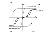
- FIG. 1 is a graph showing the magnetic characteristics of a MnAl alloy having metamagnetism.
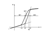
- FIG. 2 is a graph showing the magnetic properties of the MnAl alloy having metamagnetism, and shows only the first quadrant (I).
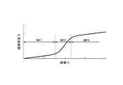
- FIG. 3 is another graph showing the magnetic properties of the MnAl alloy having metamagnetism.
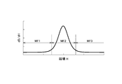
- FIG. 4 is a graph showing the differential values of the characteristics shown in FIG.
- FIG. 5 is a graph showing the twice differential value of the characteristic shown in FIG.
- FIG. 6 is a schematic view of an electrodeposition apparatus for producing a MnAl alloy.
- FIG. 7 is a schematic phase diagram of a MnAl alloy.
- FIG. 8 is a composite map of the sample of Comparative Example 1.
- FIG. 9 is a composite map of the sample of Example 4.
- FIG. 10 is a table showing the evaluation results.
- Metamagnetism refers to the property of a primary phase transition from paramagnetism (PM) or anti-ferromagnetism (AFM) to ferromagnetism (FM) by a magnetic field.
- PM paramagnetism
- AFM anti-ferromagnetism
- FM ferromagnetism
- Metamagnetic materials are classified into PM-FM transition type metamagnetic materials that transition from paramagnetic to ferromagnetic by a magnetic field, and AFM-FM transition type metamagnetic materials that transition from antiferromagnetic to ferromagnetic by a magnetic field.
- a PM-FM transition type metamagnetic material undergoes a primary phase transition only near the Curie temperature, whereas an AFM-FM transition type metamagnetic material has a primary phase at or below the Neel temperature at which the antiferromagnetic state disappears. Metastasis occurs. Since the MnAl alloy according to the present embodiment is an AFM-FM transition type metamagnetic material, it exhibits metamagnetism at a wide range of temperatures.
- the MnAl alloy according to the present embodiment has crystal particles including a ⁇ -MnAl phase and crystal particles including a ⁇ 2-MnAl phase.
- a crystal particle containing the ⁇ -MnAl phase is a phase having ferromagnetism alone, and a crystal particle containing the ⁇ 2-MnAl phase is a phase having no ferromagnetism alone.
- the value of B / A is 0.2 or more, By controlling to 21.0 or less, AFM-FM transition type metamagnetism can be realized, and metamagnetism at a wide range of temperatures can be obtained.
- the ⁇ -MnAl phase is a crystal phase having a tetragonal structure and has ferromagnetism as a single substance. However, if the area ratio with respect to the ⁇ 2-MnAl phase is within the above range, the ⁇ -MnAl phase is antiferromagnetic. And metamagnetism is exhibited.
- the ⁇ 2-MnAl phase is also called an Al 8 Mn 5 phase, Mn 11 Al 15 phase, r-MnAl phase, or ⁇ -MnAl phase, but has a rhombohedral structure and lattice constants a and b of 1. It refers to a crystal phase having 26 nm, c is about 0.79 nm, and the ratio of Mn to Al is about 31 to 47 atomic%.
- the magnetic structure of the ⁇ -MnAl phase contained in the MnAl alloy has an antiferromagnetic structure.
- An antiferromagnetic structure refers to a structure in which the spin that is the origin of magnetization of a magnetic material has a spatially periodic structure and does not have magnetization as a whole magnetic material (ie, spontaneous magnetization). This is different from a paramagnetic structure that does not have periodicity, has a disordered magnetic structure, and does not have magnetization as a whole.
- An AFM-FM transition-type metamagnetic material is realized by using a MnAl alloy in which antiferromagnetism is stable in the absence of a magnetic field before the phase transition.
- the antiferromagnetic stability when the stability of the antiferromagnetic state is too high, the magnetic field required for the magnetic phase transition to ferromagnetism becomes too large, and the magnetic phase transition due to the magnetic field cannot be caused substantially.
- the antiferromagnetic stability if the antiferromagnetic stability is too low, it may become ferromagnetic even in the absence of a magnetic field or a very weak magnetic field.
- the MnAl alloy can exhibit metamagnetism at a wide range of temperatures by adjusting the stability of the antiferromagnetic state and adding AFM-FM transition type metamagnetism.
- the crystal particles containing the ⁇ -MnAl phase in the MnAl alloy according to the present embodiment are preferably composed only of the ⁇ -MnAl phase having an antiferromagnetic structure, but some of them contain a ferromagnetic, paramagnetic, or ferrimagnetic structure. It does not matter.
- the antiferromagnetic structure of the ⁇ -MnAl phase in the MnAl alloy may be a collinear antiferromagnetic structure with a constant spin axis or a non-collinear antiferromagnetic structure with a constant spin axis.
- an antiferromagnetic structure having a long-period magnetic structure is preferable in terms of application because a magnetic field required for transition from antiferromagnetism to ferromagnetism becomes small.
- Al sites in the ⁇ -MnAl phase in the MnAl alloy according to the present embodiment are occupied by Al, but the atoms occupying the Al sites are p Any atom is acceptable as long as it has orbital valence electrons.
- Cl, Br, I, At can be candidates.
- the MnAl alloy according to the present embodiment preferably includes a ⁇ -MnAl phase, and when the composition formula of the ⁇ -MnAl phase is expressed as Mn a Al 100-a , it is preferable that 48 ⁇ a ⁇ 55 is satisfied.
- the ⁇ -MnAl phase in which a ⁇ 48 is not preferable in terms of application because the amount of Mn at the Al site is small, the antiferromagnetic state is very stable, and the magnetic field required for the magnetic phase transition is large. In the ⁇ -MnAl phase where a ⁇ 55, Mn is more easily contained than Al, so that Mn is easily substituted at the Al site.
- Mn substituted at the Al site is antiferromagnetically coupled with Mn at the Mn site, thereby causing ferromagnetic coupling between Mn at the Mn site, and ferrimagnetization of the entire ⁇ -MnAl phase.
- Metamagnetism is difficult to obtain.
- the AFM-FM transition-type metamagnetism is realized by adjusting the stability of the antiferromagnetic state in the absence of a magnetic field by setting the ratio of Mn in the ⁇ -MnAl phase to 48 ⁇ a ⁇ 55. Can be obtained.
- the MnAl alloy according to this embodiment is preferably composed only of crystal particles containing a ⁇ -MnAl phase and crystal particles containing a ⁇ 2-MnAl phase, but the value of B / A is in the above range, and As long as it has metamagnetism, it may contain a different phase such as a ⁇ -MnAl phase or an amorphous phase. Further, as long as the value of B / A is within the above range and has metamagnetism, even if it is a multi-component MnAl alloy in which a part of Mn site or Al site is substituted with Fe, Co, Cr or Ni I do not care.
- the composition ratio of Mn and Al in the MnAl alloy is not particularly limited, but it is preferable that Mn is 45 atomic% or more and less than 55 atomic%, Al is more than 45 atomic%, and 55 atomic% or less. It is particularly preferably 45 atomic% or more and 52 atomic% or less. That is, when the composition formula of the MnAl alloy is represented by Mn b Al 100-b , it is preferable that 45 ⁇ b ⁇ 55 is satisfied, and it is particularly preferable that 45 ⁇ b ⁇ 52 is satisfied. If the composition ratio of Mn and Al is set within this range, the above-described B / A value can be easily controlled to 0.2 or more and 21.0 or less.
- the value of B / A is not particularly limited as long as it is 0.2 or more and 21.0 or less, but by controlling it to 0.2 or more and less than 4.0, there is no residual magnetization and a more pure metamagnetism is obtained. It becomes possible. In particular, if the B / A value is controlled to be 1.0 or more and less than 4.0, a large saturation magnetization can be obtained. As will be described later, the value of B / A can be controlled by the heat treatment temperature for the MnAl alloy composed of the ⁇ -MnAl phase.
- the particle size of the crystal particles is small to some extent, and the average crystal particle size of the crystal particles containing the ⁇ -MnAl phase is 0.1 ⁇ m or more and 1.0 ⁇ m or less. Preferably there is.
- FIG. 1 is a graph showing the magnetic characteristics of the MnAl alloy according to the present embodiment.
- the horizontal axis (X axis) as the first axis shows the magnetic field H
- the vertical axis (Y axis) as the second axis shows the magnetization M. Is shown.
- symbol AFM-FM indicates the magnetic properties of the MnAl alloy according to the present embodiment
- symbol SM indicates the magnetic properties of a general soft magnetic material
- symbol HM indicates the magnetic properties of a general hard magnetic material. ing.
- a general soft magnetic material has high permeability in a low magnetic field region and is easily magnetized.
- magnetic saturation occurs. It shows the property of being hardly magnetized.
- the differential value of the magnetization M with respect to the magnetic field H is large in the magnetic field region where the magnetic saturation is not performed, and the differential value of the magnetization M with respect to the magnetic field H is small in the magnetic field region where the magnetic saturation occurs.
- the characteristic curve indicated by symbol SM passes through the graph origin or the vicinity thereof. Therefore, the characteristic curve indicated by symbol SM appears in the first quadrant (I) and the third quadrant (III) of the graph, and does not substantially appear in the second quadrant (II) and the fourth quadrant (IV).
- a general hard magnetic material has a large hysteresis, and a magnetized state is maintained even if the magnetic field is zero. For this reason, the characteristic curve indicated by symbol HM appears in all of the first quadrant (I) to the fourth quadrant (IV) of the graph.
- the MnAl alloy according to the present embodiment is transparent in the low magnetic field region, as indicated by reference numeral AFM-FM in the first quadrant (I) and the third quadrant (III) of the graph. Since the magnetic susceptibility is low, it is hardly magnetized, and in the medium magnetic field region, the magnetic permeability becomes high and easily magnetized. Further, in the strong magnetic field region, magnetic saturation occurs, and the magnetic field beyond that is hardly magnetized. Depending on the electrodeposition conditions and heat treatment conditions described later, there is a slight hysteresis in the first quadrant (I) and the third quadrant (III), but the residual magnetization is zero or very small. The characteristic curve substantially passes through the origin of the graph.
- FIG. 2 is a graph showing the magnetic characteristics of the MnAl alloy according to the present embodiment, and shows only the first quadrant (I).
- the magnetic characteristics of the MnAl alloy according to the present embodiment will be described in more detail with reference to FIG. 2.
- the region up to the first magnetic field strength H1 (the first magnetic field region).
- the magnetic permeability is low, so that the increase in magnetization M is slight.
- the slope of the graph that is, the differential value of the magnetization M with respect to the magnetic field H is linked to the magnetic permeability.
- the magnetic permeability in the first magnetic field region MF1 is substantially the same as the magnetic permeability of the nonmagnetic material. Therefore, the first magnetic field region MF1 substantially behaves as a nonmagnetic material.
- the magnetic permeability in the region from the first magnetic field strength H1 to the second magnetic field strength H2 (second magnetic field region MF2), the magnetic permeability increases rapidly, and the value of the magnetization M increases significantly. That is, as the magnetic field is increased, the magnetic permeability rapidly increases with the first magnetic field strength H1 as a boundary.
- the magnetic permeability in the second magnetic field region MF2 is close to the magnetic permeability of the soft magnetic material, and therefore behaves softly in the second magnetic field region MF2.
- FIG. 3 is another graph showing the magnetic characteristics of the MnAl alloy according to the present embodiment.
- the horizontal axis as the first axis shows the magnetic field H, and the vertical axis as the second axis shows the magnetic flux density B.
- the magnetic characteristics of the MnAl alloy according to the present embodiment draw a similar characteristic curve in the first quadrant (I) of the graph. That is, the inclination is small in the first magnetic field region MF1 that is a low magnetic field, the inclination is rapidly increased in the second magnetic field region MF2 that is a medium magnetic field, and the inclination is large in the third magnetic field region MF3 that is a strong magnetic field. Becomes smaller again. Also in the graph shown in FIG. 3, the characteristic curve indicating the magnetic characteristics of the MnAl alloy according to the present embodiment substantially passes through the origin, and even when it does not strictly pass through the origin of the graph, the horizontal axis or the vertical axis Passes near the origin.
- FIG. 4 is a graph showing the differential value of the characteristic shown in FIG. 3
- FIG. 5 is a graph showing the double differential value of the characteristic shown in FIG.
- the characteristics shown in FIG. 4 correspond to the differential magnetic permeability of the MnAl alloy according to the present embodiment.
- the differential value becomes maximum in the second magnetic field region MF2.
- the differential value remains small.
- the twice differentiated value is inverted from a positive value to a negative value in the second magnetic field region MF2.
- the twice differential value is almost zero.
- the MnAl alloy according to the present embodiment is obtained by precipitating a MnAl alloy by electrolyzing a molten salt in which a Mn compound and an Al compound are mixed and dissolved, and then heat-treating the MnAl alloy at a predetermined temperature.
- FIG. 6 is a schematic view of an electrodeposition apparatus for producing a MnAl alloy.
- the electrodeposition apparatus shown in FIG. 6 includes an alumina crucible 2 arranged inside a stainless steel sealed container 1.
- the alumina crucible 2 holds the molten salt 3, and the molten salt 3 in the alumina crucible 2 is heated by an electric furnace 4 disposed outside the sealed container 1.
- a cathode 5 and an anode 6 immersed in the molten salt 3 are provided in the alumina crucible 2, and a current is supplied to the cathode 5 and the anode 6 via a constant current power supply device 7.
- the cathode 5 is a plate-like body made of Cu
- the anode 6 is a plate-like body made of Al.
- the molten salt 3 in the alumina crucible 2 can be stirred by the stirrer 8.
- the inside of the sealed container 1 is filled with an inert gas such as N 2 supplied via the gas path 9.
- the molten salt 3 contains at least a Mn compound and an Al compound.
- MnCl 2 can be used as the Mn compound
- AlCl 3 , AlF 3 , AlBr 3, or AlNa 3 F 6 can be used as the Al compound.
- the Al compound may be AlCl 3 alone, or a part thereof may be substituted with AlF 3 , AlBr 3, or AlNa 3 F 6 .
- another halide may be added to the molten salt 3.
- an alkali metal halide such as NaCl, LiCl or KCl is preferably selected, and LaCl 3 , DyCl 3 , MgCl 2 , CaCl 2 , GaCl 3 , InCl 3 , GeCl 4 are used as the alkali metal halide.
- SnCl 4 , NiCl 2 , CoCl 2 , FeCl 2 and other rare earth halides, alkaline earth halides, typical element halides, transition metal halides, and the like may be added.
- the molten salt 3 can be obtained by charging such an Mn compound, Al compound and another halide into the alumina crucible 2 and heating and melting them in the electric furnace 4. Further, it is preferable that the molten salt 3 is sufficiently stirred by the stirrer 8 immediately after melting so that the composition distribution of the molten salt 3 becomes uniform.
- the electrolysis of the molten salt 3 is performed by passing a current between the cathode 5 and the anode 6 via the constant current power supply device 7. Thereby, a MnAl alloy can be deposited on the cathode 5.
- the heating temperature of the molten salt 3 during electrolysis is preferably 150 ° C. or more and 450 ° C. or less, and the amount of electricity is preferably 15 mAh or more and 150 mAh per 1 cm 2 of electrode area.
- the current flowing between the cathode 5 and the anode 6 is reduced to a powder in the cathode 5 by setting the amount of electricity per 1 mass% of the Mn compound in the molten salt 3 and the amount of electricity per 1 cm 2 of electrode area to 50 mAh or more.
- a shaped MnAl alloy can be deposited. This is because the higher the concentration of the Mn compound in the molten salt 3 is, the more the precipitation is promoted, and the more the amount of electricity per unit electrode area is, the more the precipitation is promoted. As a result, the above numerical range (50 mAh or more) is satisfied. This is because the deposited MnAl alloy tends to be powdered.
- the MnAl alloy deposited on the cathode 5 is in the form of a powder, the MnAl alloy deposition does not stop even when electrolysis is performed for a long time, so that the productivity of the MnAl alloy can be increased. Moreover, it becomes possible to obtain arbitrary product shapes by compression-molding the obtained powdered MnAl alloy.
- the initial concentration of the Mn compound in the molten salt 3 is preferably 0.2 mass% or more, and more preferably 0.2 mass% or more and 3 mass% or less. Moreover, it is preferable to maintain the concentration of the Mn compound in the molten salt 3 by additionally introducing the Mn compound during electrolysis.
- the additional Mn compound to be added may be in the form of a powder or a pellet formed by molding the powder, and this may be added to the molten salt 3 continuously or periodically.
- the concentration of the Mn compound in the molten salt 3 is maintained at a predetermined value or more. Can do. Thereby, it becomes possible to suppress the dispersion
- the composition of the MnAl alloy deposited by electrolysis is such that when Mn is 45 atomic% or more and less than 55 atomic%, and Al is more than 45 atomic% and 55 atomic% or less, the whole is precipitated in the state of ⁇ -MnAl phase.
- MnAl phase MnAl alloy When heat treatment is applied to the ⁇ -MnAl phase MnAl alloy, it is separated into a ⁇ -MnAl phase and a ⁇ 2-MnAl phase. This is because the Al-rich region where the Al concentration is increased changes to a ⁇ 2-MnAl phase and the region where the Al concentration is lowered becomes a Mn-rich ⁇ -MnAl phase as a result of the movement of Al caused by the heat treatment. it is conceivable that.
- the ratio between the ⁇ 2-MnAl phase and the ⁇ -MnAl phase varies depending on the heat treatment temperature.
- FIG. 7 is a schematic phase diagram of the MnAl alloy, in which the horizontal axis indicates the Mn ratio, and the vertical axis indicates the temperature.
- the phase diagram shown in FIG. 7 is partly based on prediction, and not entirely based on actual measurement results.
- the ratio of the ⁇ 2-MnAl phase and the ⁇ -MnAl phase changes with the heat treatment temperature, and the Mn concentration of the ⁇ -MnAl phase changes.
- the value of B / A is 0.2 or more and 21.0 or less. If the heat treatment temperature is adjusted, metamagnetism is imparted to the MnAl alloy.
- the MnAl alloy according to the present embodiment can be applied to various electronic components. For example, if the MnAl alloy according to the present embodiment is used as a magnetic core, it can be applied to a reactor, an inductor, a current limiter, an electromagnetic actuator, a motor, and the like. Moreover, if the MnAl alloy according to the present embodiment is used as a magnetic refrigeration working material, it can be applied to a magnetic refrigerator.
- the B / A value is controlled by precipitating the MnAl alloy by the electrodeposition method and then heat-treating it, but the method for producing the MnAl alloy is limited to this. is not.
- an MnAl alloy in an amorphous state is obtained by quenching a molten MnAl alloy obtained by a melting method by a liquid quenching method or an atomizing method, and then heat-treating this to obtain a B / A value. It is also possible to control.
- it is also possible to control the value of B / A by obtaining an amorphous MnAl alloy by a thin film method such as a sputtering method or a vapor deposition method and then heat-treating it.
- the cathode 5 is a Cu plate having a thickness of 3 mm cut so that the immersion area in the molten salt 3 is 5 cm ⁇ 8 cm, and the anode 6 is 3 mm in thickness cut so that the immersion area in the molten salt 3 is 5 cm ⁇ 8 cm.
- An Al plate was used.
- the alumina crucible 2 charged with the material was moved to the inside of the sealed container 1, and the material was heated to 350 ° C. by the electric furnace 4 to obtain a molten salt 3.
- the rotating blades of the stirrer 8 were allowed to settle in the molten salt 3 and stirred for 0.5 hours at a rotation speed of 300 rpm.
- a constant current of 60 mA / cm 2 (2.4 A) per unit electrode area was passed between the cathode 5 and the anode 6 with the molten salt held at 200 ° C., 250 ° C. or 300 ° C. for 4 hours. And heating was stopped.
- the electrode was removed, and the cathode 5 was ultrasonically cleaned with acetone.
- a film-like electrodeposit and a powder-like electrodeposit (MnAl alloy) were deposited on the surface of the cathode 5.
- the film-like electrodeposit was collected by dissolving and removing Cu constituting the cathode 5 with concentrated nitric acid, and pulverized in a mortar to obtain a powder.
- the powdered electrodeposit a part of it remains on the cathode 5, but the rest is deposited on the bottom of the alumina crucible 2.
- the powdered electrodeposits settled in the molten salt 3 are collected by filtration, the molten salt is decanted, and the mixture of the powdered electrodeposits and the molten salt remaining at the bottom is cooled and solidified, and then acetone is added. And then recovered by filtration.
- the powdered electrodeposits obtained by any of the recovery methods were mixed together with the powdered sample obtained by pulverizing the filmed electrodeposits.
- Example 1 A sample with a heat treatment temperature of 400 ° C. is Example 1, a sample with 425 ° C. is Example 2, a sample with 450 ° C. is Example 3, a sample with 475 ° C. is Example 4, and a sample with 500 ° C. is implemented Example 5, Sample with 550 ° C. as Example 6, Sample with 562 ° C. as Example 7, Sample with heat treatment temperature of 600 ° C. as Comparative Example 4, Sample with heat treatment temperature as 650 ° C. as Comparative Example 5, Heat treatment A sample with a temperature of 700 ° C. was designated as Comparative Example 6. Further, Samples obtained by subjecting the sample powders of Comparative Examples 2 and 3 to heat treatment at 550 ° C. for 16 hours in an Ar atmosphere were designated as Examples 8 and 9, respectively.
- Mn metal with a purity of 99.9% by mass or more and Al metal with a purity of 99.9% by mass or more are weighed at a ratio of 55 at% of Mn metal and 45 at% of Al metal, respectively, and are arc-melted in an Ar atmosphere as raw materials An ingot was produced.
- the obtained raw material ingot was heat-treated at 1150 ° C. for 2 hours in an Ar atmosphere, and then subjected to an underwater quenching treatment. Thereafter, the ingot was heat-treated in an Ar atmosphere at 600 ° C. for 1 hour and then slowly cooled. Then, it grind
- the obtained sample was set as Comparative Example 7.
- the surface of the sample prepared in the above was dry-polished with abrasive paper.
- the polishing paper is polished by rough polishing with coarse polishing paper (# 600), further polishing with medium polishing paper (# 1200), and finally polishing with fine polishing paper (# 3000).
- the surface was a mirror surface.
- FIB processing The sample mirror-finished with was processed into a flake shape with an FIB apparatus.
- STEM-EDS Measurement (Scanning Transmission Electron Microscopy-Energy Dispersive Spectroscopy: Scanning Transmission Electron Microscopy-Energy Dispersive X-ray Spectroscopy) 3. above.
- the STEM-EDS measurement was performed on the cross-section of the thin piece obtained in the above using an aberration correction TEM apparatus at an acceleration voltage of 300 kV.
- an EDS map was acquired by performing 100 measurements for 600 seconds at a resolution of 512 ⁇ 512 pixels in a 10 ⁇ m ⁇ 10 ⁇ m field of view, and turning on image drift correction.
- an Al map showing the distribution of Al-rich MnAl crystal particles and an Mn map showing the distribution of Mn-rich MnAl crystal particles were generated.
- FIG. 8 is a composite map of the sample of Comparative Example 1
- FIG. 9 is a composite map of the sample of Example 7.
- FIG. 8 it can be seen that in the sample of Comparative Example 1 where heat treatment was not performed, Mn and Al were almost uniformly dispersed.
- the sample of Example 7 subjected to the heat treatment at 562 ° C. for 16 hours is separated into a Mn-rich region and an Al-rich region.
- Electron diffraction images were confirmed by TEM (Transmission Electron Microscopy) analysis for Al-rich MnAl crystal particles and Mn-rich MnAl crystal particles, and phase identification was performed. As a result, Al-rich MnAl crystal particles were identified as a ⁇ 2-MnAl phase, and Mn-rich MnAl crystal particles were identified as a ⁇ -MnAl phase. Further, ⁇ -MnAl phase was also confirmed in the samples of Comparative Examples 5 and 6.
- the peak due to the magnetic structure can be obtained by removing the peak due to the crystal structure obtained by X-ray diffraction from the diffraction peak obtained by neutron diffraction.
- the Miller index (1, 0, 1/2) indicating that ⁇ -MnAl has a magnetic structure with a double period in the c-axis direction has a Miller index l of 1/2 and is a rational number. It can be seen that the magnetic structure has a double period in the direction.
- the samples of Examples 1 to 9 in which the MnAl alloy obtained by the molten salt electrolysis method (electrodeposition method) was heat-treated at 400 ° C. to 562 ° C. had an area ratio (B / A) of 0. 2 to 21.0, all showing metamagnetism.
- the samples of Examples 4 to 9 having an area ratio (B / A) of 0.2 or more and less than 4.0 did not have remanent magnetization, and almost pure metamagnetism was obtained.
- the saturation magnetization values of the samples of Examples 4 to 7 having an area ratio (B / A) of 1.0 or more and less than 4.0 were very large.
- the average crystal grain size of Mn-rich MnAl crystal particles ( ⁇ -MnAl phase) was 0.24 to 0.91.
- the samples of Comparative Examples 1 to 7 had an area ratio B / A of less than 0.2 or more than 21.0, and none showed metamagnetism. Among these, the samples of Comparative Examples 1 to 3 and 7 showed ferromagnetism and had remanent magnetization. On the other hand, the samples of Comparative Examples 4 to 6 were nonmagnetic.
- the samples of Examples 1 to 9 all have a ⁇ -MnAl phase and a ⁇ 2-MnAl phase, and have an antiferromagnetic structure in the absence of a magnetic field. Was confirmed. Further, in the samples of Examples 1 to 9, the Mn ratio in the MnAl alloy is 45 atom% or more and 50 atom% or less, and the Mn ratio in the ⁇ -MnAl phase is 48 atom% or more and 53.5 atoms. % Or less.
- Example 5 the magnetic properties of the samples of Example 5 and Comparative Examples 1 and 7 were evaluated in the temperature range of ⁇ 100 ° C. to 200 ° C. The results are shown in Table 1.
- Example 5 As shown in Table 1, the sample of Example 5 exhibited metamagnetism in a wide temperature range of ⁇ 100 ° C. to 200 ° C.
Landscapes
- Chemical & Material Sciences (AREA)
- Engineering & Computer Science (AREA)
- Materials Engineering (AREA)
- Metallurgy (AREA)
- Organic Chemistry (AREA)
- Mechanical Engineering (AREA)
- Chemical Kinetics & Catalysis (AREA)
- Electrochemistry (AREA)
- Thermal Sciences (AREA)
- Crystallography & Structural Chemistry (AREA)
- Physics & Mathematics (AREA)
- Soft Magnetic Materials (AREA)
- Hard Magnetic Materials (AREA)
Abstract
幅広い温度でメタ磁性を示すMn系合金を提供することを課題とする。本発明によるMnAl合金は、メタ磁性を有し、τ-MnAl相を含む結晶粒子とγ2-MnAl相を含む結晶粒子を有する。好ましくは、所定の断面における、τ-MnAl相を含む結晶粒子の面積をB、γ2-MnAl相を含む結晶粒子の面積をAとした場合、B/Aの値が0.2以上、21.0以下である。τ-MnAl相を含む結晶粒子とγ2-MnAl相を含む結晶粒子の面積比をこの範囲に制御すれば、MnAl合金にメタ磁性が与えられ、幅広い温度、特に-100℃~200℃の温度範囲でメタ磁性を得ることができる。
Description
本発明はMnAl合金に関し、特に、メタ磁性を有するMnAl合金に関する。
MnAl合金は、古くから磁性材料として知られている。例えば、特許文献1に開示されたMnAl合金は正方晶構造を有し、MnとAlの原子比を5:4とすることにより磁性を示すことが開示されている。また、特許文献2には、正方晶構造を有するMnAl合金からなる第一相と、Al8Mn5結晶粒からなる第二相を混在させることにより、MnAl合金を保磁力の高い永久磁石として利用できることが示されている。
また、特許文献3に示されているように、Mnを主たる構成元素とする磁性材料の一部は、メタ磁性を示すことが知られている。メタ磁性とは、磁場により常磁性または反強磁性から強磁性に転移する性質である。メタ磁性を示すメタ磁性材料は、磁気冷凍器やアクチュエーター、限流器への応用が期待されている。
しかしながら、特許文献3に記載されたメタ磁性材料は、いずれも磁場による常磁性から強磁性への一次相転移を利用しているため、キュリー温度近傍でしかメタ磁性を発現しない。このため、現実的には限流器などへの応用が困難であった。
本発明は、上記に鑑みてなされたものであって、幅広い温度でメタ磁性を示すMn系合金を提供することを目的とする。
上述した課題を解決し目的を達成するために、本発明者は磁場による反強磁性から強磁性に転移するタイプのメタ磁性材料(以下、「AFM-FM転移型メタ磁性材料」という)に注目した。AFM-FM転移型メタ磁性材料は、反強磁性秩序がなくなるネール温度以下であればメタ磁性が発現するため、常磁性から強磁性に転移するタイプのメタ磁性材料(以下、「PM-FM転移型メタ磁性材料」という)のように、キュリー温度近傍という狭い温度帯に維持する必要がないからである。
AFM-FM転移型メタ磁性を実現するには、高い結晶磁気異方性を持ち、且つ、反強磁性を有することが必要となる。そこで、AFM-FM転移型メタ磁性材料として、単体で反強磁性を示すMnを用いたMn系磁性材料に着目し、様々な合金・化合物について検討を行った。その結果、Mn系合金の中でも強磁性を示す比較的稀有であるMnAl合金に反強磁性的な要素を付与することで、幅広い温度でメタ磁性を示すことを見出した。本発明は、かかる知見に基づいて完成されたものであり、本発明によるMnAl合金は、メタ磁性を有し、τ-MnAl相を含む結晶粒子とγ2-MnAl相を含む結晶粒子を有することを特徴とする。
本発明者は、MnAl合金についてさらに鋭意研究を行った結果、τ-MnAl相を含む結晶粒子とγ2-MnAl相を含む結晶粒子が所定の比率で混在している場合にメタ磁性が容易に発現することを見いだした。つまり、単体ではτ-MnAl相の結晶粒子は強磁性を示し、γ2-MnAl相の結晶粒子は非磁性を示すのであるが、これらを所定の比率で混在させると、τ-MnAl相に反強磁性が付与され、AFM-FM転移型のメタ磁性を示すことが明らかとなった。
具体的には、τ-MnAl相を含む結晶粒子とγ2-MnAl相を含む結晶粒子を有するMnAl合金において、所定の断面における、前記τ-MnAl相を含む結晶粒子の面積をB、前記γ2-MnAl相を含む結晶粒子の面積をAとした場合、B/Aの値を0.2以上、21.0以下とすることにより、MnAl合金にメタ磁性が与えられ、幅広い温度、特に-100℃~200℃の温度範囲でメタ磁性を得ることができる。
また、本発明によるMnAl合金は、τ-MnAl相の磁気構造が反強磁性構造を持つことが好ましい。相転移前である無磁場において、反強磁性が安定となるMn系合金を用いることで、AFM-FM転移型メタ磁性材料が実現する。ここで、反強磁性状態の安定性が高すぎる場合は、磁場による強磁性への相転移を起こすことができない。一方、反強磁性の安定性が低すぎる場合は、無磁場又は非常に弱い磁場でも強磁性になる可能性がある。そして、MnAl合金は反強磁性状態の安定性が適度であることから、AFM-FM転移型メタ磁性を付与すれば、幅広い温度でメタ磁性を発現することができる。
AlサイトのMn量を調整することでτ-MnAl相が反強磁性化するメカニズムについて第一原理計算により検討を行ったところ、AlサイトのAl原子におけるp軌道価電子を介したMnサイトのMn同士の超交換相互作用にあることがわかった。超交換相互作用とは、遷移金属原子の3d軌道価電子が、配位子と呼ばれるp軌道価電子を有した原子におけるp軌道価電子との軌道混成を通して働く交換相互作用のメカニズムの一種である。ここで、遷移金属原子と、配位子と、結合を起こす遷移金属原子とのなす角度が180°に近い場合に、反強磁性結合を起こす。つまり、τ-MnAl相におけるMnサイトのMnと、配位子であるAlサイトのAlと、Mnサイトから(1,1,0)及び(1,1,1)方向のMnのなす角度は180°に近く、反強磁性結合を起こしたことが原因であることがわかった。加えて、AlサイトにMn原子が置換した場合、MnサイトのMn同士に超交換相互作用は生じず、反強磁性的な磁気構造は取りづらくなることもわかった。これらの結果から、τ-MnAl相におけるAlサイトのMn量を調整することで、反強磁性の安定性が調整できることがわかった。
本発明によるMnAl合金は、組成式をMnbAl100-bで表した場合、45≦b<55を満たすことが好ましく、45≦b<52を満たすことがより好ましい。MnとAlの比率をこの範囲に設定すれば、MnAl合金にメタ磁性を付与することが可能となる。さらに、本発明によるMnAl合金は、τ-MnAl相の組成式をMnaAl100-aで表した場合、48≦a<55を満たすことが好ましい。
本発明において、B/Aの値は1.0以上、4.0未満であっても構わない。これによれば、残留磁化の少ないより純粋なメタ磁性が得られるとともに、高い飽和磁化を得ることが可能となる。
本発明において、τ-MnAl相を含む結晶粒子の平均結晶粒径は0.1μm以上、1.0μm以下であることが好ましい。これによれば、τ-MnAl相を含む結晶粒子とγ2-MnAl相を含む結晶粒子が緻密に混合されることから、メタ磁性を発現しやすくなる。
このように、本発明によれば、幅広い温度でメタ磁性を示すMnAl合金を提供することが可能となる。
以下、本発明の好適な実施形態について説明する。なお、本発明は以下に記載の実施形態及び実施例の内容により限定されるものではない。また、以下に記載の実施形態及び実施例にて示された構成要素は適宜組み合わせても良いし、適宜選択してもよい。
メタ磁性とは、磁場により常磁性(PM:Paramagnetic)もしくは反強磁性(AFM:Anti-Ferromagnetic)から強磁性(FM:Ferromagnetic)に一次相転移する性質を指す。磁場による一次相転移とは、磁場に関する磁化の変化が不連続になる点をもつことを指す。メタ磁性材料は、磁場により常磁性から強磁性に転移するPM-FM転移型メタ磁性材料と、磁場により反強磁性から強磁性に転移するAFM-FM転移型メタ磁性材料に分類される。PM-FM転移型メタ磁性材料は、キュリー温度の近傍でのみ一次相転移が生じるのに対し、AFM-FM転移型メタ磁性材料は、反強磁性状態が消失するネール温度以下であれば一次相転移が生じる。そして、本実施形態によるMnAl合金は、AFM-FM転移型メタ磁性材料であることから、幅広い温度でメタ磁性を発現する。
本実施形態によるMnAl合金は、τ-MnAl相を含む結晶粒子と、γ2-MnAl相を含む結晶粒子を有している。τ-MnAl相を含む結晶粒子はそれ単体で強磁性を有する相であり、γ2-MnAl相を含む結晶粒子はそれ単体で強磁性を持たない相である。そして、MnAl合金の所定の断面における、τ-MnAl相を含む結晶粒子の面積をB、γ2-MnAl相を含む結晶粒子の面積をAとした場合、B/Aの値を0.2以上、21.0以下に制御することにより、AFM-FM転移型メタ磁性を実現し、幅広い温度でのメタ磁性を得ることができる。τ-MnAl相は正方晶構造を有する結晶相であり、単体では強磁性を有しているが、γ2-MnAl相との面積比を上記の範囲とすれば、τ-MnAl相に反強磁性が付与され、メタ磁性を発現する。
γ2-MnAl相とは、他にもAl8Mn5相、Mn11Al15相、r-MnAl相、γ-MnAl相と呼ばれるが、菱面体晶構造を持ち、格子定数a及びbが1.26nm、cが0.79nm程度、Alに対するMnの比率が31~47原子%程度を有する結晶相を指す。
本実施形態においては、MnAl合金に含まれるτ-MnAl相の磁気構造が反強磁性構造を有している。反強磁性構造とは、磁性体の磁化の起源となるスピンが空間的に周期的な構造を持ち、磁性体全体としての磁化(すなわち自発磁化)を持たない構造を指し、スピンが空間的な周期性を持たず無秩序な磁気構造を持ち磁性体全体としての磁化を持たない常磁性構造とは異なる。相転移前である無磁場において、反強磁性が安定となるMnAl合金を用いることで、AFM-FM転移型メタ磁性材料が実現する。ここで、反強磁性状態の安定性が高すぎる場合は、強磁性への磁気相転移に必要な磁場が大きくなりすぎ、実質的に磁場による磁気相転移を起こすことができない。一方、反強磁性の安定性が低すぎる場合は、無磁場又は非常に弱い磁場でも強磁性になる可能性がある。そして、MnAl合金は反強磁性状態の安定性が調整し、AFM-FM転移型メタ磁性を付与すれば、幅広い温度でメタ磁性を発現することができる。
本実施形態によるMnAl合金におけるτ-MnAl相を含む結晶粒子は、反強磁性構造を持つτ-MnAl相のみで構成されることが好ましいが一部に強磁性や常磁性、フェリ磁性構造を含んでいても構わない。また、メタ磁性を有する限り、MnAl合金におけるτ-MnAl相の反強磁性構造は、スピン軸が一定であるコリニア型反強磁性構造でも、スピン軸が一定でないノンコリニア型反強磁性構造でも構わないが、長周期の磁気構造となる反強磁性構造の方が反強磁性から強磁性に転移することに必要な磁場が小さくなり、応用上好ましい。
本実施形態によるMnAl合金におけるτ-MnAl相に反強磁性構造を持たせるためには、τ-MnAl相におけるAlサイトがAlに占有されることが好ましいが、Alサイトを占有する原子は、p軌道価電子を持つ限りどのような原子でも構わない。具体的には、p軌道価電子を持つB、Ga、In、Tl、C、Si、Ge、Sn、Pb、N、P、As、Sb、Bi、O、S,Se、Te、Po、F、Cl、Br、I、Atがその候補となりうる。
本実施形態によるMnAl合金は、τ-MnAl相を含み、τ-MnAl相の組成式をMnaAl100-aで表した場合、48≦a<55を満たしていることが好ましい。a<48であるτ-MnAl相は、AlサイトのMn量が少なくなり、反強磁性状態の安定性が非常に高く、磁気相転移に必要な磁場が大きくなり、応用上好ましくない。a≧55であるτ-MnAl相は、MnがAlよりも多く含まれることからAlサイトにMnが置換されやすい。Alサイトに置換したMnは、MnサイトのMnと反強磁性的に結合することで、MnサイトのMn間が強磁性的な結合を起こし、τ-MnAl相全体としてはフェリ磁性化することで、メタ磁性が得にくくなる。τ-MnAl相のMnの割合を48≦a<55とし、無磁場での反強磁性状態の安定性を調整することで、AFM-FM転移型メタ磁性を実現し、幅広い温度でのメタ磁性を得ることができる。
本実施形態によるMnAl合金は、τ-MnAl相を含む結晶粒子と、γ2-MnAl相を含む結晶粒子のみで構成されることが好ましいが、B/Aの値が上記の範囲であり、且つ、メタ磁性を有する限り、β-MnAl相、アモルファス相などの異相を含んでいても構わない。また、B/Aの値が上記の範囲であり、且つ、メタ磁性を有する限り、Mnサイト又はAlサイトの一部がFe、Co、Cr又はNiで置換された多元系MnAl合金であっても構わない。
MnAl合金中におけるMnとAlの組成比については特に限定されないが、Mnが45原子%以上、55原子%未満であり、Alが45原子%超、55原子%以下であることが好ましく、Mnが45原子%以上、52原子%以下であることが特に好ましい。つまり、MnAl合金の組成式をMnbAl100-bで表した場合、45≦b<55を満たすことが好ましく、45≦b≦52を満たすことが特に好ましい。MnとAlの組成比をこの範囲に設定すれば、上述したB/Aの値を0.2以上、21.0以下に制御しやすくなる。
B/Aの値は、0.2以上、21.0以下であれば特に限定されないが、0.2以上、4.0未満に制御することにより残留磁化がなくなり、より純粋なメタ磁性を得ることが可能となる。中でも、B/Aの値を1.0以上、4.0未満に制御すれば、大きな飽和磁化を得ることも可能となる。後述するように、B/Aの値は、τ-MnAl相からなるMnAl合金に対する熱処理温度によって制御することができる。熱処理によってB/Aの値を制御するためには、結晶粒子の粒子径がある程度小さいことが好ましく、τ-MnAl相を含む結晶粒子の平均結晶粒径が0.1μm以上、1.0μm以下であることが好ましい。
図1は、本実施形態によるMnAl合金の磁気特性を示すグラフであり、第1軸である横軸(X軸)は磁場Hを示し、第2軸である縦軸(Y軸)は磁化Mを示している。図1において、符号AFM-FMは本実施形態によるMnAl合金の磁気特性を示し、符号SMは一般的な軟磁性材料の磁気特性を示し、符号HMは一般的な硬磁性材料の磁気特性を示している。
図1において符号SMで示すように、一般的な軟磁性材料は、低磁場領域においては透磁率が高く容易に磁化される一方、磁場強度が所定値を超えると磁気飽和を起こし、それ以上はほとんど磁化されないという特性を示す。言い換えれば、磁気飽和しない磁場領域では、磁場Hに対する磁化Mの微分値が大きく、磁気飽和する磁場領域では、磁場Hに対する磁化Mの微分値が小さくなる。また、一般的な軟磁性材料は、ヒステリシスが無い、或いは、ヒステリシスが非常に小さいことから、符号SMで示す特性曲線は、グラフの原点又はその近傍を通る。したがって、符号SMで示す特性曲線は、グラフの第1象限(I)及び第3象限(III)に現れ、第2象限(II)及び第4象限(IV)には実質的に現れない。
図1において符号HMで示すように、一般的な硬磁性材料は大きなヒステリシスを有しており、磁場がゼロであっても磁化された状態が維持される。このため、符号HMで示す特性曲線は、グラフの第1象限(I)~第4象限(IV)の全てに現れる。
これらの一般的な強磁性材料に対し、本実施形態によるMnAl合金は、グラフの第1象限(I)及び第3象限(III)において符号AFM-FMで示すように、低磁場領域においては透磁率が低いためほとんど磁化されず、中磁場領域においては透磁率が高くなって容易に磁化され、さらに、強磁場領域になると磁気飽和を起こし、それ以上はほとんど磁化されないという特性を示す。後述する電析条件及び熱処理条件によっては、第1象限(I)及び第3象限(III)内において僅かにヒステリシスが存在するが、残留磁化はゼロ又は非常に小さいため、符号AFM-FMで示す特性曲線は実質的にグラフの原点を通る。符号AFM-FMで示す特性曲線が厳密にグラフの原点を通らない場合であっても、横軸又は縦軸の原点近傍を通ることになる。このことは、本実施形態によるMnAl合金が初期状態であるか、或いは、繰り返し磁場を印加した後の状態であるかにかかわらず、同じ磁気特性が得られることを意味する。
図2は、本実施形態によるMnAl合金の磁気特性を示すグラフであり、第1象限(I)のみを示している。
図2を用いて本実施形態によるMnAl合金の磁気特性についてより具体的に説明すると、磁場Hが無い状態から磁場を高めていくと、第1の磁場強度H1までの領域(第1の磁場領域MF1)においては透磁率が低く、このため磁化Mの増加は僅かである。グラフの傾き、つまり、磁場Hに対する磁化Mの微分値は透磁率に連動する。第1の磁場領域MF1における透磁率は非磁性材料の透磁率と同程度であり、したがって、第1の磁場領域MF1においては実質的に非磁性材料として振る舞う。
一方、第1の磁場強度H1から第2の磁場強度H2までの領域(第2の磁場領域MF2)においては透磁率が急激に高くなり、磁化Mの値は大幅に増加する。つまり、磁場を高めていくと、第1の磁場強度H1を境として透磁率が急激に増加する。第2の磁場領域MF2における透磁率は軟磁性材料の透磁率に近く、したがって、第2の磁場領域MF2においては軟磁性的に振る舞う。
さらに磁場を高めることによって第2の磁場強度H2を超えると(第3の磁場領域MF3)、磁気飽和を起こし、グラフの傾き、つまり透磁率は再び低下する。
逆に、第3の磁場領域MF3から磁場を弱めていき、第3の磁場強度H3を下回ると、第4の磁場強度H4までの領域で再び透磁率が高くなる。そして、第4の磁場強度H4を下回ると透磁率が低下し、再び非磁性材料として振る舞う。このように、第1象限(I)内においてはヒステリシスを有しているものの、残留磁化はほとんど存在しないため、磁場Hを一旦ゼロ近辺に戻せば、再び上述した特性と同じ特性が得られる。
尚、図1及び図2に示したグラフは縦軸が磁化Mであるが、縦軸を磁束密度Bに置き換えても、同様の関係が成り立つ。
図3は、本実施形態によるMnAl合金の磁気特性を示す別のグラフであり、第1軸である横軸は磁場Hを示し、第2軸である縦軸は磁束密度Bを示している。
図3に示すように、縦軸を磁束密度Bに置き換えた場合であっても、本実施形態によるMnAl合金の磁気特性は、グラフの第1象限(I)において同様の特性曲線を描く。つまり、低磁場である第1の磁場領域MF1においては傾きが小さく、中磁場である第2の磁場領域MF2においては傾きが急激に大きくなり、強磁場である第3の磁場領域MF3においては傾きが再び小さくなる。また、図3に示すグラフにおいても、本実施形態によるMnAl合金の磁気特性を示す特性曲線は実質的に原点を通り、厳密にグラフの原点を通らない場合であっても、横軸又は縦軸の原点近傍を通る。
図4は図3に示す特性の微分値を示すグラフであり、図5は図3に示す特性の二回微分値を示すグラフである。図4に示す特性は、本実施形態によるMnAl合金の微分透磁率に相当する。
図4に示すように、図3に示す特性を一回微分すると、第2の磁場領域MF2において微分値が極大となる。第1の磁場領域MF1及び第3の磁場領域MF3では、微分値は小さい値のままである。そして、図5に示すように、図3に示す特性を二回微分すると、第2の磁場領域MF2において二回微分値が正の値から負の値に反転する。第1の磁場領域MF1及び第3の磁場領域MF3では、二回微分値はほぼゼロである。このように、本実施形態によるMnAl合金は、磁場Hに対して磁束密度Bを二回微分すると、二回微分値が正の値から負の値に反転するという特徴を有している。
本実施形態によるMnAl合金は、Mn化合物とAl化合物を混合溶解した溶融塩を電解することによってMnAl合金を析出させた後、このMnAl合金を所定の温度で熱処理することによって得られる。
図6は、MnAl合金を製造するための電析装置の模式図である。
図6に示す電析装置は、ステンレス製の密閉容器1の内部に配置されたアルミナ坩堝2を備えている。アルミナ坩堝2は溶融塩3を保持するものであり、密閉容器1の外部に配置された電気炉4によってアルミナ坩堝2内の溶融塩3が加熱される。アルミナ坩堝2内には、溶融塩3に浸漬する陰極5及び陽極6が設けられており、これら陰極5及び陽極6には、定電流電源装置7を介して電流が供給される。陰極5はCuからなる板状体であり、陽極6はAlからなる板状体である。アルミナ坩堝2内の溶融塩3は、攪拌機8によって攪拌することが可能である。また、密閉容器1の内部は、ガス経路9を介して供給されるN2などの不活性ガスで満たされる。
溶融塩3は、少なくともMn化合物およびAl化合物を含む。Mn化合物としてはMnCl2を用いることができ、Al化合物としてはAlCl3、AlF3、AlBr3又はAlNa3F6を用いることができる。Al化合物はAlCl3単独であっても構わないし、その一部をAlF3、AlBr3又はAlNa3F6によって置換しても構わない。
溶融塩3は、上述したMn化合物およびAl化合物の他に、別のハロゲン化物を添加しても構わない。別のハロゲン化物としては、NaCl、LiCl又はKClなどのアルカリ金属ハロゲン化物を選択することが好ましく、アルカリ金属ハロゲン化物にLaCl3、DyCl3、MgCl2、CaCl2、GaCl3、InCl3、GeCl4、SnCl4、NiCl2、CoCl2、FeCl2などの希土類ハロゲン化物、アルカリ土類ハロゲン化物、典型元素ハロゲン化物、遷移金属ハロゲン化物などを添加しても構わない。
このようなMn化合物、Al化合物及び別のハロゲン化物をアルミナ坩堝2にチャージし、電気炉4によって加熱溶融させることによって、溶融塩3を得ることができる。また、溶融塩3の組成分布が均一となるよう、溶融直後は攪拌機8によって溶融塩3を十分に攪拌することが好ましい。
溶融塩3の電解は、定電流電源装置7を介して陰極5と陽極6との間に電流を流すことによって行う。これにより、陰極5にMnAl合金を析出させることができる。電解中における溶融塩3の加熱温度は、150℃以上、450℃以下とすることが好ましく、電気量については、電極面積1cm2当たりの電気量を15mAh以上、150mAhとすることが好ましい。電解中においては、密閉容器1の内部をN2などの不活性ガスで満たすことが好ましい。
また、陰極5と陽極6との間に流す電流は、溶融塩3中におけるMn化合物の濃度1mass%当たり、且つ、電極面積1cm2当たりの電気量を50mAh以上とすることにより、陰極5に粉末状のMnAl合金を析出させることができる。これは、溶融塩3中におけるMn化合物の濃度が高いほど析出が促進されるとともに、単位電極面積当たりの電気量が多いほど析出が促進される結果、上記の数値範囲(50mAh以上)を満たすことによって、析出するMnAl合金が粉末状になりやすくなるからである。陰極5に析出するMnAl合金が粉末状であれば、電解を長時間行ってもMnAl合金の析出が停止することがないため、MnAl合金の生産性を高めることができる。また、得られた粉状体のMnAl合金を圧縮成形することによって、任意の製品形状を得ることも可能となる。
溶融塩3中におけるMn化合物の初期濃度は、0.2mass%以上であることが好ましく、0.2mass%以上、3mass%以下であることがより好ましい。また、電解中にMn化合物を追加投入することによって、溶融塩3中におけるMn化合物の濃度を維持することが好ましい。追加投入するMn化合物は、粉末状あるいは粉末を成形したペレット状とし、これを溶融塩3に連続的又は定期的に追加すればよい。このように、溶融塩3の電解中にMn化合物を追加投入すれば、電解の進行に伴うMn化合物の濃度低下が抑制され、溶融塩3中におけるMn化合物の濃度を所定値以上に維持することができる。これにより、析出するMnAl合金の組成のばらつきを抑制することが可能となる。
電解によって析出したMnAl合金の組成は、Mnが45原子%以上、55原子%未満であり、Alが45原子%超、55原子%以下である場合、ほぼ全体がτ-MnAl相の状態で析出する。そして、τ-MnAl相のMnAl合金に対して熱処理を施すと、τ-MnAl相とγ2-MnAl相に分離する。これは、熱処理によってAlの移動が生じる結果、Al濃度が上昇したAlリッチな領域がγ2-MnAl相に変化するとともに、Al濃度が低下した領域はMnリッチなτ-MnAl相となるためであると考えられる。そして、γ2-MnAl相とτ-MnAl相の割合は、熱処理温度によって変化する。
図7は、MnAl合金の模式的な相図であり、横軸はMn比率を示し、縦軸は温度を示している。但し、図7に示す相図は一部予測によるものであり、全てが実測結果に基づくものではない。
図7に示すように、Mnの原子比率が50%であるMnAl合金を電析法によって作製した場合、ほぼ全体がτ相となる。そして、このMnAl合金に対して熱処理を行うと、Alの移動によってτ-MnAl相とγ2-MnAl相に分離する。図7において黒丸で示すポイントが各温度において存在する相を示しており、温度が高くなるほど、τ-MnAl相のMn比率が高くなることが理解できる。これに対し、温度が高くなってもγ2-MnAl相のMn比率はほとんど変わらない。このことから、熱処理によってAlの移動が発生すると、移動するAlを取り込んだ領域がγ2-MnAl相に変化する一方、Alを失った領域のMn濃度が徐々に高まるものと考えられる。
しかしながら、熱処理温度が所定値を超えるとτ-MnAl相が存在できなくなり、γ2-MnAl相とβ-MnAl相が混合した状態となる。この状態になるとτ-MnAl相が存在しないことから、磁性が失われる。
このようなメカニズムにより、熱処理温度によってγ2-MnAl相とτ-MnAl相の割合が変化するとともに、τ-MnAl相のMn濃度が変化するものと予想される。そして、τ-MnAl相を含む結晶粒子の面積をB、γ2-MnAl相を含む結晶粒子の面積をAとした場合、B/Aの値が0.2以上、21.0以下となるよう、熱処理温度を調整すれば、MnAl合金にメタ磁性が与えられる。その理由については定かではないが、B/Aの値が上記の範囲であれば、τ-MnAl相に反強磁性が付与され、AFM-FM転移型のメタ磁性を示すものと考えられる。
本実施形態によるMnAl合金は、様々な電子部品に応用することが可能である。例えば、本実施形態によるMnAl合金を磁心として用いれば、リアクトル、インダクタ、限流器、電磁アクチュエーター、モータなどへの応用が可能である。また、本実施形態によるMnAl合金を磁気冷凍作業物質として用いれば、磁気冷凍機への応用が可能である。
以上、本発明の好ましい実施形態について説明したが、本発明は、上記の実施形態に限定されることなく、本発明の主旨を逸脱しない範囲で種々の変更が可能であり、それらも本発明の範囲内に包含されるものであることはいうまでもない。
例えば、上記の実施形態では、電析法によってMnAl合金を析出させた後、これを熱処理することによってB/Aの値を制御しているが、MnAl合金の作製方法がこれに限定されるものではない。別の作製方法として、溶解法によって得られたMnAl合金の溶湯を液体急冷法またはアトマイズ法によって急冷することによってアモルファス状態のMnAl合金を得た後、これを熱処理することによってB/Aの値を制御することも可能である。さらに別の作製方法として、スパッタリング法や蒸着法などの薄膜法によってアモルファス状態のMnAl合金を得た後、これを熱処理することによってB/Aの値を制御することも可能である。
<溶融塩電解法によるMnAl合金の作製>
まず、図6に示す構造を有する電析装置を用意した。陰極5は、溶融塩3への浸漬面積が5cm×8cmとなるよう切断した厚み3mmのCu板を用い、陽極6は、溶融塩3への浸漬面積が5cm×8cmとなるよう切断した厚み3mmのAl板を用いた。
まず、図6に示す構造を有する電析装置を用意した。陰極5は、溶融塩3への浸漬面積が5cm×8cmとなるよう切断した厚み3mmのCu板を用い、陽極6は、溶融塩3への浸漬面積が5cm×8cmとなるよう切断した厚み3mmのAl板を用いた。
次に、Al化合物である無水AlCl3と、別のハロゲン化物であるNaClをそれぞれ50mol%ずつ秤量し、Mn化合物として予め脱水処理したMnCl2を1mass%秤量し、総重量が1200gとなるようアルミナ坩堝2に投入した。したがって、MnCl2の量は12gである。脱水処理は、MnCl2水和物をN2ガスなどの不活性雰囲気中で約400℃、4時間以上加熱することにより行った。
材料が投入されたアルミナ坩堝2を密閉容器1の内部に移動し、電気炉4によって材料を350℃に加熱することによって溶融塩3を得た。次に、攪拌機8の回転羽根を溶融塩3に沈降させ、300rpmの回転数で0.5時間撹拌した。その後、溶融塩を200℃、250℃又は300℃に保持した状態で、陰極5と陽極6の間に単位電極面積当たり60mA/cm2(2.4A)の定電流を4時間通電し、電流および加熱を停止した。そして、溶融塩3が冷却固化する前に電極を離脱し、陰極5をアセトンで超音波洗浄した。陰極5の表面には、膜状の電析物と粉状の電析物(MnAl合金)が析出していた。膜状の電析物は、陰極5を構成するCuを濃硝酸で溶解除去することによって回収し、乳鉢で粉砕して粉末状とした。粉状の電析物については、一部が陰極5に残留するものの、残りはアルミナ坩堝2の底部に堆積する。このため、溶融塩3中に沈降した粉末状の電析物をろ過回収するとともに、溶融塩をデカンテーションし、底部に残った粉末状の電析物と溶融塩の混合物を冷却固化後、アセトンで洗浄し、ろ過回収した。いずれの回収法で得られた粉末状電析物も、膜状電析物を粉砕した粉末状サンプルと合わせて混合した。
<MnAl合金の熱処理>
電析温度が300℃、250℃、200℃である場合に得られた粉末試料をそれぞれ比較例1~3とした。
電析温度が300℃、250℃、200℃である場合に得られた粉末試料をそれぞれ比較例1~3とした。
また、比較例1の試料粉末をAr雰囲気中で400℃~700℃、16時間の熱処理を行った。熱処理温度を400℃としたサンプルを実施例1、425℃としたサンプルを実施例2、450℃としたサンプルを実施例3、475℃としたサンプルを実施例4、500℃としたサンプルを実施例5、550℃としたサンプルを実施例6、562℃としたサンプルを実施例7、熱処理温度を600℃としたサンプルを比較例4、熱処理温度を650℃としたサンプルを比較例5、熱処理温度を700℃としたサンプルを比較例6とした。さらに、比較例2及び3の試料粉末をAr雰囲気中で550℃、16時間の熱処理を施したサンプルをそれぞれ実施例8及び9とした。
<溶解法によるMnAl合金の作製>
純度99.9質量%以上のMnメタルと純度99.9質量%以上のAlメタルを、それぞれMnメタルを55at%、Alメタルを45at%の割合で秤量し、Ar雰囲気中でアーク溶解して原料インゴットを作製した。
純度99.9質量%以上のMnメタルと純度99.9質量%以上のAlメタルを、それぞれMnメタルを55at%、Alメタルを45at%の割合で秤量し、Ar雰囲気中でアーク溶解して原料インゴットを作製した。
得られた原料インゴットをAr雰囲気中で1150℃にて、2時間加熱処理を行った後、水中急冷処理を行った。その後、インゴットをAr雰囲気中で600℃にて、1時間の熱処理を行った後、徐冷した。その後、スタンプミルにて粉砕を行い、100μm以下の粉末を得た。得られたサンプルを比較例7とした。
<磁気特性の評価>
実施例1~9及び比較例1~7のサンプルに対し、パルス励磁型磁気特性測定装置(東英工業製)を用いて室温にて0~100kOeの磁場範囲での磁気特性を測定し、得られた磁化曲線からメタ磁性の有無を判定した。さらに、100kOeにおける質量磁化を最大質量磁化σmax、0kOe付近での磁化を残留質量磁化σrとし、その比率σr/σmaxを角型比とした。そして、角型比が0.1以上の試料を残留磁化有りと判定し、角型比が0.1未満の試料を残留磁化なしと判定した。
実施例1~9及び比較例1~7のサンプルに対し、パルス励磁型磁気特性測定装置(東英工業製)を用いて室温にて0~100kOeの磁場範囲での磁気特性を測定し、得られた磁化曲線からメタ磁性の有無を判定した。さらに、100kOeにおける質量磁化を最大質量磁化σmax、0kOe付近での磁化を残留質量磁化σrとし、その比率σr/σmaxを角型比とした。そして、角型比が0.1以上の試料を残留磁化有りと判定し、角型比が0.1未満の試料を残留磁化なしと判定した。
<τ相/γ2相の面積比率の評価>
1.測定粉体の樹脂埋め
実施例1~9及び比較例1~7のサンプルのそれぞれと熱硬化性樹脂(G2樹脂)を体積比で等量程度をよく混合した後にFIB(Focused Ion Beam:集束イオンビーム)用試料台(ピンスタブ)上に塗布し、真空脱泡した後にホットプレートを用いて120℃で1時間加熱し硬化させた。
1.測定粉体の樹脂埋め
実施例1~9及び比較例1~7のサンプルのそれぞれと熱硬化性樹脂(G2樹脂)を体積比で等量程度をよく混合した後にFIB(Focused Ion Beam:集束イオンビーム)用試料台(ピンスタブ)上に塗布し、真空脱泡した後にホットプレートを用いて120℃で1時間加熱し硬化させた。
2.表面研磨処理
上記1.で作製した試料の表面を研磨紙で乾式研磨した。研磨紙の順序は粗い研磨紙(#600)で粗研磨した後、中程度の研磨紙(#1200)でさらに研磨し、最終的に細かい研磨紙(#3000)で仕上げ研磨することによって、研磨面を鏡面とした。
上記1.で作製した試料の表面を研磨紙で乾式研磨した。研磨紙の順序は粗い研磨紙(#600)で粗研磨した後、中程度の研磨紙(#1200)でさらに研磨し、最終的に細かい研磨紙(#3000)で仕上げ研磨することによって、研磨面を鏡面とした。
3.FIB加工
上記2.で鏡面加工した試料をFIB装置によって薄片状に加工した。
上記2.で鏡面加工した試料をFIB装置によって薄片状に加工した。
4.STEM-EDS測定(Scanning Transmission Electron Microscopy-Energy Dispersive Spectroscopy:走査型透過電子顕微鏡-エネルギー分散型X線分光分析)
上記3.で得た薄片の断面に対し、収差補正TEM装置を用いて300kVの加速電圧でSTEM-EDS測定を実施した。具体的には、10μm×10μmの視野に対して512×512ピクセルの解像度で600秒間に亘って100回の測定を行い、像のドリフト補正をONにしてEDSマップを取得した。これにより、AlリッチなMnAl結晶粒子の分布を示すAlマップと、MnリッチなMnAl結晶粒子の分布を示すMnマップを生成した。
上記3.で得た薄片の断面に対し、収差補正TEM装置を用いて300kVの加速電圧でSTEM-EDS測定を実施した。具体的には、10μm×10μmの視野に対して512×512ピクセルの解像度で600秒間に亘って100回の測定を行い、像のドリフト補正をONにしてEDSマップを取得した。これにより、AlリッチなMnAl結晶粒子の分布を示すAlマップと、MnリッチなMnAl結晶粒子の分布を示すMnマップを生成した。
5.画像合成
上記4.で得たAlマップとMnマップをEDS測定ソフト上で合成することにより、合成マップを生成した。図8は比較例1のサンプルの合成マップであり、図9は実施例7のサンプルの合成マップである。図8に示すように、熱処理を行っていない比較例1のサンプルは、MnとAlがほぼ均一に分散していることが分かる。これに対し、562℃で16時間の熱処理を行った実施例7のサンプルは、Mnリッチな領域とAlリッチな領域に分離していることが分かる。
上記4.で得たAlマップとMnマップをEDS測定ソフト上で合成することにより、合成マップを生成した。図8は比較例1のサンプルの合成マップであり、図9は実施例7のサンプルの合成マップである。図8に示すように、熱処理を行っていない比較例1のサンプルは、MnとAlがほぼ均一に分散していることが分かる。これに対し、562℃で16時間の熱処理を行った実施例7のサンプルは、Mnリッチな領域とAlリッチな領域に分離していることが分かる。
6.結晶構造の評価
AlリッチなMnAl結晶粒子とMnリッチなMnAl結晶粒子に対し、TEM(Transmission Electron Microscopy)分析により電子線回折像を確認し、相同定を行った。その結果、AlリッチなMnAl結晶粒子はγ2-MnAl相と同定され、MnリッチなMnAl結晶粒子はτ-MnAl相と同定された。また、比較例5,6のサンプルには、β-MnAl相も確認された。
AlリッチなMnAl結晶粒子とMnリッチなMnAl結晶粒子に対し、TEM(Transmission Electron Microscopy)分析により電子線回折像を確認し、相同定を行った。その結果、AlリッチなMnAl結晶粒子はγ2-MnAl相と同定され、MnリッチなMnAl結晶粒子はτ-MnAl相と同定された。また、比較例5,6のサンプルには、β-MnAl相も確認された。
7.面積比率の評価
上記5.で得た合成マップを画像解析・画像計測ソフトウェアで解析し、AlリッチなMnAl結晶粒子が占める面積(A)と、MnリッチなMnAl結晶粒子が占める面積(B)を測定した。そして、測定領域の面積(M)に対する面積Aの比(A/M)及び面積Bの比(B/M)を算出した後、
(B/M)/(A/M)=B/A
を計算した。
上記5.で得た合成マップを画像解析・画像計測ソフトウェアで解析し、AlリッチなMnAl結晶粒子が占める面積(A)と、MnリッチなMnAl結晶粒子が占める面積(B)を測定した。そして、測定領域の面積(M)に対する面積Aの比(A/M)及び面積Bの比(B/M)を算出した後、
(B/M)/(A/M)=B/A
を計算した。
<平均結晶粒径の評価>
上記1.(測定粉体の樹脂埋め)、2.(表面研磨処理)、3.(FIB加工)を行った試料に対し、STEM(Scanning TransmissionElectron Microscopy:走査型透過電子顕微鏡)による観察を行い、BF(Bright Field:明視野)画像を撮影した。測定範囲は10μm×10μmである。次に、画像解析・画像計測ソフトウェアにて、MnリッチなMnAl結晶粒子(τ-MnAl相)の結晶粒子径Dを計測した。サンプリング数は100個とし、平均結晶粒径を算出した。ここで、結晶粒子径Dは円相当径を使用したため、結晶粒子径Dと面積Sは以下の関係を満たす。
D=√(4S/π)
上記1.(測定粉体の樹脂埋め)、2.(表面研磨処理)、3.(FIB加工)を行った試料に対し、STEM(Scanning TransmissionElectron Microscopy:走査型透過電子顕微鏡)による観察を行い、BF(Bright Field:明視野)画像を撮影した。測定範囲は10μm×10μmである。次に、画像解析・画像計測ソフトウェアにて、MnリッチなMnAl結晶粒子(τ-MnAl相)の結晶粒子径Dを計測した。サンプリング数は100個とし、平均結晶粒径を算出した。ここで、結晶粒子径Dは円相当径を使用したため、結晶粒子径Dと面積Sは以下の関係を満たす。
D=√(4S/π)
<磁気構造の評価>
粉末試料を、飛行時間中性子回折法により面間隔dが1~40オングストロームの範囲を測定し、τ-MnAlの結晶構造よりも長周期な磁気構造が観測された場合を反強磁性の磁気構造を有する結晶粒子があると判断した。長周期な磁気構造の有無は、磁気構造に起因する回折ピークのミラー指数(h,k,l)が、τ-MnAlの結晶構造を基準として指数付けした場合に、整数とならない場合に、長周期な磁気構造があると判定できる。ここで、磁気構造に起因するピークは、中性子回折で得られた回折ピークからX線回折で得られた結晶構造起因のピークを除くことで、得られる。例えば、τ-MnAlのc軸方向に2倍周期の磁気構造を有することを示すミラー指数(1,0,1/2)は、ミラー指数lが1/2となり有理数となるために、c軸方向に2倍周期の磁気構造を有することがわかる。
粉末試料を、飛行時間中性子回折法により面間隔dが1~40オングストロームの範囲を測定し、τ-MnAlの結晶構造よりも長周期な磁気構造が観測された場合を反強磁性の磁気構造を有する結晶粒子があると判断した。長周期な磁気構造の有無は、磁気構造に起因する回折ピークのミラー指数(h,k,l)が、τ-MnAlの結晶構造を基準として指数付けした場合に、整数とならない場合に、長周期な磁気構造があると判定できる。ここで、磁気構造に起因するピークは、中性子回折で得られた回折ピークからX線回折で得られた結晶構造起因のピークを除くことで、得られる。例えば、τ-MnAlのc軸方向に2倍周期の磁気構造を有することを示すミラー指数(1,0,1/2)は、ミラー指数lが1/2となり有理数となるために、c軸方向に2倍周期の磁気構造を有することがわかる。
<評価結果>
評価結果を図10に示す。
評価結果を図10に示す。
図10に示すように、溶融塩電解法(電析法)によって得られたMnAl合金を400℃~562℃で熱処理した実施例1~9のサンプルは、面積比率(B/A)が0.2~21.0であり、いずれもメタ磁性を示した。特に、面積比率(B/A)が0.2以上、4.0未満である実施例4~9のサンプルは残留磁化を有しておらず、ほぼ純粋なメタ磁性が得られた。中でも、面積比率(B/A)が1.0以上、4.0未満である実施例4~7のサンプルは飽和磁化の値が非常に大きかった。また、実施例1~9のサンプルは、MnリッチなMnAl結晶粒子(τ-MnAl相)の平均結晶粒径が0.24~0.91であった。
これに対し、比較例1~7のサンプルは、面積比率B/Aが0.2未満または21.0超であり、いずれもメタ磁性を示さなかった。このうち、比較例1~3,7のサンプルは強磁性を示し、残留磁化を有していた。一方、比較例4~6のサンプルは非磁性であった。
また、実施例1~9のサンプルは、いずれもτ-MnAl相とγ2-MnAl相が混在しており、且つ、τ-MnAl相が無磁場の状態で反強磁性構造を有していることが確認された。さらに、実施例1~9のサンプルは、MnAl合金中におけるMn比率が45原子%以上、50原子%以下であり、且つ、τ-MnAl相中におけるMn比率が48原子%以上、53.5原子%以下であった。
次に、実施例5、比較例1及び7のサンプルに対し、温度を-100℃~200℃の温度範囲で磁気特性の評価を行った。結果を表1に示す。

表1に示すように、実施例5のサンプルは-100℃~200℃という広い温度範囲でメタ磁性を示した。
1 密閉容器
2 アルミナ坩堝
3 溶融塩
4 電気炉
5 陰極
6 陽極
7 定電流電源装置
8 攪拌機
9 ガス経路
2 アルミナ坩堝
3 溶融塩
4 電気炉
5 陰極
6 陽極
7 定電流電源装置
8 攪拌機
9 ガス経路
Claims (8)
- メタ磁性を有し、τ-MnAl相を含む結晶粒子とγ2-MnAl相を含む結晶粒子を有するMnAl合金。
- 所定の断面における、前記τ-MnAl相を含む結晶粒子の面積をB、前記γ2-MnAl相を含む結晶粒子の面積をAとした場合、B/Aの値が0.2以上、21.0以下であることを特徴とする請求項1に記載のMnAl合金。
- 前記B/Aの値が1.0以上、4.0未満であることを特徴とする請求項2に記載のMnAl合金。
- 前記τ-MnAl相を含む結晶粒子の平均結晶粒径が0.1μm以上、1.0μm以下であることを特徴とする請求項1乃至3のいずれか一項に記載のMnAl合金。
- 組成式をMnbAl100-bで表した場合、45≦b<55を満たす請求項1乃至4のいずれか一項に記載のMnAl合金。
- 45≦b<52を満たす請求項5に記載のMnAl合金。
- 前記τ-MnAl相の磁気構造が、無磁場の状態において反強磁性構造を有する請求項1乃至6のいずれか一項に記載のMnAl合金。
- 前記τ-MnAl相の組成式をMnaAl100-aで表した場合、48≦a<55を満たす請求項7に記載のMnAl合金。
Priority Applications (3)
| Application Number | Priority Date | Filing Date | Title |
|---|---|---|---|
| JP2019507534A JP7028239B2 (ja) | 2017-03-22 | 2018-03-09 | MnAl合金 |
| US16/485,595 US11261508B2 (en) | 2017-03-22 | 2018-03-09 | MnAl alloy |
| CN201880019726.6A CN110446797A (zh) | 2017-03-22 | 2018-03-09 | MnAl合金 |
Applications Claiming Priority (2)
| Application Number | Priority Date | Filing Date | Title |
|---|---|---|---|
| JP2017-055459 | 2017-03-22 | ||
| JP2017055459 | 2017-03-22 |
Publications (1)
| Publication Number | Publication Date |
|---|---|
| WO2018173786A1 true WO2018173786A1 (ja) | 2018-09-27 |
Family
ID=63585239
Family Applications (1)
| Application Number | Title | Priority Date | Filing Date |
|---|---|---|---|
| PCT/JP2018/009139 Ceased WO2018173786A1 (ja) | 2017-03-22 | 2018-03-09 | MnAl合金 |
Country Status (4)
| Country | Link |
|---|---|
| US (1) | US11261508B2 (ja) |
| JP (1) | JP7028239B2 (ja) |
| CN (1) | CN110446797A (ja) |
| WO (1) | WO2018173786A1 (ja) |
Cited By (1)
| Publication number | Priority date | Publication date | Assignee | Title |
|---|---|---|---|---|
| WO2025105244A1 (ja) * | 2023-11-14 | 2025-05-22 | Agc株式会社 | 磁性粒子を製造する方法、磁性粒子、およびそれを用いた永久磁石 |
Families Citing this family (2)
| Publication number | Priority date | Publication date | Assignee | Title |
|---|---|---|---|---|
| WO2018128152A1 (ja) * | 2017-01-05 | 2018-07-12 | Tdk株式会社 | MnAl合金及びその製造方法 |
| JP7234518B2 (ja) * | 2018-06-30 | 2023-03-08 | Tdk株式会社 | MnAl合金及びその製造方法 |
Citations (3)
| Publication number | Priority date | Publication date | Assignee | Title |
|---|---|---|---|---|
| US20100218858A1 (en) * | 2005-10-27 | 2010-09-02 | Ian Baker | Nanostructured mn-al permanent magnets and methods of producing same |
| CN104593625A (zh) * | 2015-01-06 | 2015-05-06 | 同济大学 | 一种无稀土MnAl永磁合金的制备方法 |
| JP2017045824A (ja) * | 2015-08-26 | 2017-03-02 | 株式会社豊田中央研究所 | 永久磁石およびその製造方法 |
Family Cites Families (5)
| Publication number | Priority date | Publication date | Assignee | Title |
|---|---|---|---|---|
| JPH0721544A (ja) * | 1993-07-07 | 1995-01-24 | Hitachi Ltd | 磁気記録媒体及びその製造方法 |
| JP2002340616A (ja) * | 2001-05-21 | 2002-11-27 | Sanyo Special Steel Co Ltd | エンコーダー用磁気スケール材料 |
| US20120003114A1 (en) * | 2005-10-27 | 2012-01-05 | Ian Baker | Nanostructured Mn-Al Permanent Magnets And Methods of Producing Same |
| JP6115306B2 (ja) * | 2013-05-20 | 2017-04-19 | Tdk株式会社 | 磁気冷凍装置用磁気作業物質および磁気冷凍装置 |
| JP7234518B2 (ja) * | 2018-06-30 | 2023-03-08 | Tdk株式会社 | MnAl合金及びその製造方法 |
-
2018
- 2018-03-09 CN CN201880019726.6A patent/CN110446797A/zh active Pending
- 2018-03-09 WO PCT/JP2018/009139 patent/WO2018173786A1/ja not_active Ceased
- 2018-03-09 US US16/485,595 patent/US11261508B2/en not_active Expired - Fee Related
- 2018-03-09 JP JP2019507534A patent/JP7028239B2/ja active Active
Patent Citations (3)
| Publication number | Priority date | Publication date | Assignee | Title |
|---|---|---|---|---|
| US20100218858A1 (en) * | 2005-10-27 | 2010-09-02 | Ian Baker | Nanostructured mn-al permanent magnets and methods of producing same |
| CN104593625A (zh) * | 2015-01-06 | 2015-05-06 | 同济大学 | 一种无稀土MnAl永磁合金的制备方法 |
| JP2017045824A (ja) * | 2015-08-26 | 2017-03-02 | 株式会社豊田中央研究所 | 永久磁石およびその製造方法 |
Non-Patent Citations (1)
| Title |
|---|
| PARK, J.H. ET AL.: "Saturation magnetization and crystalline anisotropy calculations for MnAl permanent magnet", JOURNAL OF APPLIED PHYSICS, vol. 107, no. 9, 21 April 2010 (2010-04-21), pages 1 - 3, XP012134235, Retrieved from the Internet <URL:http://aip.scitation.org/toc/jap/107/9> * |
Cited By (1)
| Publication number | Priority date | Publication date | Assignee | Title |
|---|---|---|---|---|
| WO2025105244A1 (ja) * | 2023-11-14 | 2025-05-22 | Agc株式会社 | 磁性粒子を製造する方法、磁性粒子、およびそれを用いた永久磁石 |
Also Published As
| Publication number | Publication date |
|---|---|
| JPWO2018173786A1 (ja) | 2020-01-23 |
| JP7028239B2 (ja) | 2022-03-02 |
| US20200002790A1 (en) | 2020-01-02 |
| CN110446797A (zh) | 2019-11-12 |
| US11261508B2 (en) | 2022-03-01 |
Similar Documents
| Publication | Publication Date | Title |
|---|---|---|
| CN111246952B (zh) | 结晶质Fe基合金粉末及其制造方法 | |
| CN107614715A (zh) | 含有l10型铁镍规则相的铁镍合金组成物、含有l10型铁镍规则相的铁镍合金组成物的制造方法、以非晶作为主相的铁镍合金组成物、非晶材的母合金、非晶材、磁性材料以及磁性材料的制造方法 | |
| JP7222359B2 (ja) | R-t-b系希土類永久磁石 | |
| JP7028239B2 (ja) | MnAl合金 | |
| JP4737161B2 (ja) | 希土類−鉄−窒素系磁性粉末及びその製造方法 | |
| CN110211759A (zh) | Sm-Fe-N磁体材料和Sm-Fe-N粘结磁体 | |
| CN109952621B (zh) | 稀土-过渡金属系强磁性合金 | |
| CN110168144B (zh) | MnAl合金的制造方法 | |
| US11293085B2 (en) | MnAl alloy and manufacturing method therefor | |
| JP7017148B2 (ja) | MnAl合金及びその製造方法 | |
| Chen et al. | Influence of the Fe/Co ratio on the structural and magnetic properties of FeCoMnAlSi high-entropy alloys with varied Mn content | |
| Kelhar et al. | The role of Fe and Cu additions on the structural, thermal and magnetic properties of amorphous Al-Ce-Fe-Cu alloys | |
| JP2020007578A (ja) | MnAl合金及びこれを用いた磁心 | |
| JP6376840B2 (ja) | 永久磁石材料及びその製造方法 | |
| JP2020031114A (ja) | メタ磁性を有する合金及びこれを用いた磁心、並びに、MnAl合金の製造方法 | |
| WO2023054035A1 (ja) | 希土類磁石材料及び磁石 | |
| JP7226778B2 (ja) | SmZrFeCo磁性化合物およびその製造方法 | |
| Tang et al. | Effect of Pr substitution on the phase structure and magnetic properties of (Sm1-xPrₓ) Co₅ (x= 0–1) melt-spun ribbons | |
| JP7114970B2 (ja) | R-t-b系永久磁石 | |
| Ünalan | Development of rare-earth free permanent magnets | |
| JP2016213233A (ja) | 希土類永久磁石および希土類永久磁石の製造方法 | |
| JP2016032004A (ja) | 磁性材料、及び磁性材料の製造方法、並びに希土類磁石 | |
| JP2018174214A (ja) | 永久磁石薄膜 |
Legal Events
| Date | Code | Title | Description |
|---|---|---|---|
| 121 | Ep: the epo has been informed by wipo that ep was designated in this application |
Ref document number: 18772233 Country of ref document: EP Kind code of ref document: A1 |
|
| ENP | Entry into the national phase |
Ref document number: 2019507534 Country of ref document: JP Kind code of ref document: A |
|
| NENP | Non-entry into the national phase |
Ref country code: DE |
|
| 122 | Ep: pct application non-entry in european phase |
Ref document number: 18772233 Country of ref document: EP Kind code of ref document: A1 |