WO2018173145A1 - 内視鏡シースおよび内視鏡システム - Google Patents
内視鏡シースおよび内視鏡システム Download PDFInfo
- Publication number
- WO2018173145A1 WO2018173145A1 PCT/JP2017/011407 JP2017011407W WO2018173145A1 WO 2018173145 A1 WO2018173145 A1 WO 2018173145A1 JP 2017011407 W JP2017011407 W JP 2017011407W WO 2018173145 A1 WO2018173145 A1 WO 2018173145A1
- Authority
- WO
- WIPO (PCT)
- Prior art keywords
- endoscope
- channel
- sheath
- distal end
- longitudinal direction
- Prior art date
- Legal status (The legal status is an assumption and is not a legal conclusion. Google has not performed a legal analysis and makes no representation as to the accuracy of the status listed.)
- Ceased
Links
Images





Classifications
-
- A—HUMAN NECESSITIES
- A61—MEDICAL OR VETERINARY SCIENCE; HYGIENE
- A61B—DIAGNOSIS; SURGERY; IDENTIFICATION
- A61B1/00—Instruments for performing medical examinations of the interior of cavities or tubes of the body by visual or photographical inspection, e.g. endoscopes; Illuminating arrangements therefor
- A61B1/00131—Accessories for endoscopes
- A61B1/00135—Oversleeves mounted on the endoscope prior to insertion
-
- A—HUMAN NECESSITIES
- A61—MEDICAL OR VETERINARY SCIENCE; HYGIENE
- A61B—DIAGNOSIS; SURGERY; IDENTIFICATION
- A61B1/00—Instruments for performing medical examinations of the interior of cavities or tubes of the body by visual or photographical inspection, e.g. endoscopes; Illuminating arrangements therefor
- A61B1/00064—Constructional details of the endoscope body
- A61B1/00071—Insertion part of the endoscope body
- A61B1/0008—Insertion part of the endoscope body characterised by distal tip features
- A61B1/00091—Nozzles
-
- A—HUMAN NECESSITIES
- A61—MEDICAL OR VETERINARY SCIENCE; HYGIENE
- A61B—DIAGNOSIS; SURGERY; IDENTIFICATION
- A61B1/00—Instruments for performing medical examinations of the interior of cavities or tubes of the body by visual or photographical inspection, e.g. endoscopes; Illuminating arrangements therefor
- A61B1/00142—Instruments for performing medical examinations of the interior of cavities or tubes of the body by visual or photographical inspection, e.g. endoscopes; Illuminating arrangements therefor with means for preventing contamination, e.g. by using a sanitary sheath
- A61B1/00144—Hygienic packaging
-
- A—HUMAN NECESSITIES
- A61—MEDICAL OR VETERINARY SCIENCE; HYGIENE
- A61B—DIAGNOSIS; SURGERY; IDENTIFICATION
- A61B1/00—Instruments for performing medical examinations of the interior of cavities or tubes of the body by visual or photographical inspection, e.g. endoscopes; Illuminating arrangements therefor
- A61B1/005—Flexible endoscopes
-
- A—HUMAN NECESSITIES
- A61—MEDICAL OR VETERINARY SCIENCE; HYGIENE
- A61B—DIAGNOSIS; SURGERY; IDENTIFICATION
- A61B1/00—Instruments for performing medical examinations of the interior of cavities or tubes of the body by visual or photographical inspection, e.g. endoscopes; Illuminating arrangements therefor
- A61B1/12—Instruments for performing medical examinations of the interior of cavities or tubes of the body by visual or photographical inspection, e.g. endoscopes; Illuminating arrangements therefor with cooling or rinsing arrangements
-
- A—HUMAN NECESSITIES
- A61—MEDICAL OR VETERINARY SCIENCE; HYGIENE
- A61B—DIAGNOSIS; SURGERY; IDENTIFICATION
- A61B1/00—Instruments for performing medical examinations of the interior of cavities or tubes of the body by visual or photographical inspection, e.g. endoscopes; Illuminating arrangements therefor
- A61B1/12—Instruments for performing medical examinations of the interior of cavities or tubes of the body by visual or photographical inspection, e.g. endoscopes; Illuminating arrangements therefor with cooling or rinsing arrangements
- A61B1/126—Instruments for performing medical examinations of the interior of cavities or tubes of the body by visual or photographical inspection, e.g. endoscopes; Illuminating arrangements therefor with cooling or rinsing arrangements provided with means for cleaning in-use
-
- A—HUMAN NECESSITIES
- A61—MEDICAL OR VETERINARY SCIENCE; HYGIENE
- A61B—DIAGNOSIS; SURGERY; IDENTIFICATION
- A61B1/00—Instruments for performing medical examinations of the interior of cavities or tubes of the body by visual or photographical inspection, e.g. endoscopes; Illuminating arrangements therefor
- A61B1/313—Instruments for performing medical examinations of the interior of cavities or tubes of the body by visual or photographical inspection, e.g. endoscopes; Illuminating arrangements therefor for introducing through surgical openings, e.g. laparoscopes
- A61B1/3137—Instruments for performing medical examinations of the interior of cavities or tubes of the body by visual or photographical inspection, e.g. endoscopes; Illuminating arrangements therefor for introducing through surgical openings, e.g. laparoscopes for examination of the interior of blood vessels
-
- A—HUMAN NECESSITIES
- A61—MEDICAL OR VETERINARY SCIENCE; HYGIENE
- A61B—DIAGNOSIS; SURGERY; IDENTIFICATION
- A61B1/00—Instruments for performing medical examinations of the interior of cavities or tubes of the body by visual or photographical inspection, e.g. endoscopes; Illuminating arrangements therefor
- A61B1/00064—Constructional details of the endoscope body
- A61B1/00071—Insertion part of the endoscope body
- A61B1/00073—Insertion part of the endoscope body with externally grooved shaft
Definitions
- the present invention relates to an endoscope sheath and an endoscope system.
- an endoscope that has an injection port for injecting a cleaning liquid on the distal end surface, and is capable of cleaning adhering substances such as blood adhering to the observation target tissue by injecting the cleaning liquid onto the observation target tissue facing the distal end surface.
- a mirror is known (for example, refer to Patent Document 1).
- it has an injection port that opens toward the distal end surface of the endoscope, and the cleaning liquid is ejected from the ejection port to the distal end surface of the endoscope, thereby cleaning the deposits attached to the observation window on the distal end surface.
- An endoscope sheath that can be used is known (for example, see Patent Document 2).
- the endoscope of Patent Document 1 has an inconvenience that the observation window cannot be cleaned because the injection port is provided on the same surface as the observation window.
- the endoscope sheath of Patent Document 2 has a structure in which the cleaning liquid is ejected in the radial direction from an ejection port provided in the vicinity of the distal end of the endoscope sheath, the endoscope sheath faces the distal end surface of the endoscope. There is an inconvenience that the tissue to be observed cannot be washed.
- the present invention has been made in view of the above-described circumstances, and is an endoscope that can clean both the observation window of the endoscope and the observation range of the observation target tissue located on the side of the endoscope.
- An object is to provide a sheath and an endoscope system.
- the present invention provides the following means. According to a first aspect of the present invention, there is provided a cylindrical sheath body in which an endoscope channel into which an endoscope is inserted is formed so as to penetrate along the longitudinal direction, and the endoscope on the radially outer side of the endoscope channel.
- the protrusion part which has an injection port is provided in a part of circumferential direction at the front end side of the sheath main body, and the side facing an injection port is open
- the endoscope When it is desired to clean the observation range of the observation target tissue, the endoscope is arranged so that the endoscope is not interposed between the injection port and the observation range of the observation target tissue, and the cleaning fluid is supplied to the injection port through the fluid channel.
- the cleaning fluid By supplying, it is possible to clean the observation range by spraying the cleaning fluid ejected from the ejection port onto the observation range of the observation target tissue.
- the distal end surface of the endoscope is arranged at a position adjacent to the ejection port in the radial direction, and cleaning fluid is supplied to the ejection port via the fluid channel.
- the observation window by spraying the cleaning fluid from the ejection port to the distal end surface of the endoscope.
- a plurality of the injection ports may be provided in the projecting portion.
- the cleaning fluid can be ejected in a wide range, and the distal end surface of the endoscope and a wider range of the observation target tissue can be cleaned.
- the first aspect includes a treatment instrument channel that extends from the proximal end portion of the sheath body in the longitudinal direction and communicates with the fluid channel at an intermediate position in the longitudinal direction of the fluid channel, and into which a treatment instrument is inserted,
- the fluid channel may be capable of inserting the treatment instrument, and may extend to a treatment instrument opening that opens to a distal end surface of the projecting portion and into which the treatment instrument projects and sinks.
- the treatment tool inserted into the fluid channel from the treatment tool channel can be projected from the treatment tool opening at the tip of the protrusion.
- the fluid channel also as a channel for the treatment instrument, the diameter of the sheath body can be reduced compared to the case where a treatment instrument channel different from the fluid channel is provided over substantially the entire length of the sheath body. Can do.
- the protruding portion may have a substantially partial cylindrical shape having a notch cut in the longitudinal direction at a part of the circumferential direction.
- An endoscope according to a second aspect of the present invention includes the endoscope sheath according to any one of the above and an endoscope that is inserted along a longitudinal direction into the endoscope channel of the endoscope sheath. It is a mirror system.
- the endoscope may be movable in the longitudinal direction within the endoscope channel. In this way, the endoscope is elongated between the position where the distal end surface of the endoscope is adjacent to the ejection port and the position where the distal end surface of the endoscope is located on the proximal side of the ejection port. By moving in the direction, the object to be cleaned by the cleaning fluid can be switched between the observation window and the observation range of the observation target tissue.
- the position restricting portion that restricts the relative position in the longitudinal direction of the endoscope sheath and the endoscope at a position where the distal end of the endoscope is aligned with the ejection port in the radial direction. You may have. By doing so, the relative positions of the endoscope sheath and the endoscope can be regulated so that the distal end surface of the endoscope is disposed at a position suitable for cleaning the observation window.
- the endoscope includes a bendable bendable portion at a distal end portion, and the bendable portion in the endoscope channel is curved so that the bendable portion is bent to the side opposite to the ejection port.
- the endoscope sheath and the endoscope may be formed in an integral structure.
- the present invention it is possible to clean both the observation window of the endoscope and the observation range of the observation target tissue located on the side of the endoscope.
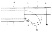
- FIG. 1 is an overall configuration diagram of an endoscope sheath and an endoscope system including the same according to an embodiment of the present invention. It is a side view of the front-end
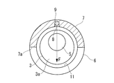
- FIG. 2 is a transverse sectional view of the endoscope sheath taken along the line II in FIG. 1.
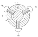
- FIG. 2 is a diagram illustrating a configuration of a fixing unit, and is a transverse cross-sectional view taken along a line II-II of the endoscope sheath of FIG. It is a figure explaining the usage method of the endoscope system of FIG. It is a side view of the front-end
- an endoscope sheath 1 and an endoscope system 100 includes an endoscope 2 and an endoscope sheath 1 having an endoscope channel 11 into which the endoscope 2 can be inserted.
- the endoscope 2 includes a thin and long flexible insertion portion 3 that can be inserted into the pericardial cavity, and a bending portion 4 that is provided at the distal end of the insertion portion 3 and can be bent in at least one direction. I have.
- the endoscope 2 is a direct-view type in which an observation window 5 (see FIG. 3) is provided on a distal end surface 3a perpendicular to the longitudinal axis of the insertion portion 3.
- An objective lens (not shown) and an imaging device (not shown) are provided at the distal end portion of the endoscope 2, and light incident on the observation window 5 is imaged by the objective lens, and the formed image is formed by the imaging device. Images are being taken.
- a fiber bundle is provided in the endoscope 2 along the longitudinal direction, and an image formed by the objective lens is optically transmitted by the fiber bundle to an imaging element provided at the proximal end portion of the endoscope 2. You may be comprised so that.
- the image signal acquired by the imaging device is electrically transmitted to the image processor, and is generated into an endoscopic image by the image processor, and the endoscopic image is displayed on the monitor.
- the endoscope 2 scans the laser light two-dimensionally on the subject, receives the reflected light of the laser light from the subject through the observation window 5, and based on the scanning position of the laser light and the intensity of the reflected light.
- An optical scanning endoscope that generates a two-dimensional image of the subject may be used.
- the endoscope sheath 1 includes a cylindrical sheath body 6 having a longitudinal axis and opening at both ends, and a projecting portion 7 projecting in the longitudinal direction from the distal end of the sheath body 6 connected to the distal end of the sheath body 6.
- a fixing part (position restricting part, rotation restricting part) 10 for fixing the posture.
- the sheath body 6 is flexible so that it can be bent along the tissue shape in the living body.
- an endoscope channel 11 is formed that penetrates along the longitudinal axis from the proximal end opening of the proximal end face of the sheath body 6 to the distal end opening 11 a of the distal end face.
- the endoscope channel 11 has an inner diameter larger than the outer diameter of the insertion portion 3, and the insertion portion 3 can be moved in the longitudinal direction and rotated around the longitudinal axis in the endoscope channel 11.
- the protruding portion 7 has a substantially partial cylindrical shape having a notch 7a cut in the longitudinal direction at a part of the circumferential direction.
- the protruding portion 7 protrudes along a longitudinal direction of the sheath body 6 from a circumferential portion of the annular distal end surface of the sheath body 6 surrounding the distal end opening 11a, and when the sheath body 6 is viewed in the longitudinal direction from the distal end side.
- the endoscope channel 11 is disposed outside in the radial direction.
- the protruding portion 7 has a length dimension extending to a position protruding from the distal end surface 3a of the insertion portion 3 in a state where the curved portion 4 protrudes from the distal end opening 11a.
- the width of the notch 7 a in the radial direction of the sheath body 6 is larger than the diameter of the curved portion 4.
- the protruding portion 7 shown in the figure has a substantially semi-cylindrical shape with a substantially half circumference cut out over the entire length in the longitudinal direction, but the length and width of the notch 7a can be appropriately changed.
- the protrusion 7 has a rigidity capable of maintaining a substantially linear shape against the pressing force to the heart side received from the pericardium in the pericardial cavity.
- the injection port 8 opens on the inner surface of the protruding portion 7 at a position facing the notch 7 a and the endoscope channel 11 in the radial direction with the endoscope channel 11 interposed therebetween.
- the ejection port 8 has a cylindrical inner surface extending perpendicularly to the longitudinal direction of the endoscope channel 11 toward the central axis of the endoscope channel 11, and the endoscope channel 11 is directed toward the notch 7a.
- the cleaning fluid F is jetted radially inward.
- the injection port 8 is provided in the position adjacent to the front end surface 3a of the insertion part 3 in the diameter direction in the state which the curved part 4 protruded from the front end opening 11a, as FIG. 2A shows.
- the cleaning fluid F ejected from the ejection port 8 is sprayed onto the distal end surface 3a.
- the observation window 5 can be cleaned.
- the bending portion 4 is bent toward the notch 7a from the state of FIG. 2A to form a space through which the cleaning fluid F passes on the distal end side of the bending portion 4, so that the injection port 8
- the ejected cleaning fluid F can be sprayed onto the living tissue located on the side of the sheath body 6 through the endoscope channel 11 and the notch 7a to clean the living tissue.
- the fluid channel 9 is formed in the longitudinal direction on the side wall of the sheath body 6 and the protruding portion 7 from the supply port 13 to the injection port 8 provided at the proximal end portion of the sheath body 6.
- the supply port 13 is connected to a fluid source 15 that holds the cleaning fluid F through a pump 14, and the operation of the pump 14 causes the cleaning fluid F to flow from the fluid source 15 to the ejection port 8 through the supply port 13 and the fluid channel 9. Supplied.
- the cleaning fluid F may be a liquid such as physiological saline, or may be a gas that blows away living tissue and deposits such as blood on the observation window 5.
- the fixing unit 10 fixes a midway position in the longitudinal direction of the insertion unit 3 inserted into the endoscope channel 11 to the sheath body 6.
- a fixing portion 10 is provided at intervals in the circumferential direction of the sheath body 6, and the side wall of the sheath body 6 enters the endoscope channel 11 from the outside of the sheath body 6.
- the position and rotation of the insertion portion 3 in the longitudinal direction with respect to the sheath body 6 can be restricted so that the insertion portion 3 does not advance and retreat and rotate with respect to the sheath body 6.
- tip part of the set screw 10a which contacts the insertion part 3 may be coat
- the insertion portion 3 of the endoscope 2 is inserted into the endoscope channel 11 of the sheath body 6, and FIG.
- the longitudinal direction of the insertion portion 3 in the endoscope channel 11 such that the distal end surface 3a of the insertion portion 3 is adjacent to the ejection port 8 in the radial direction with the curved portion 4 extending straight.
- the posture of the insertion portion 3 around the longitudinal axis in the endoscope channel 11 is set so that the bending portion 4 is bent to the opposite side (notch 7a side) from the injection port 8. decide.
- the insertion portion 3 is fixed to the sheath body 6 by the fixing portion 10 at the determined position and posture.
- the sheath body 6 and the insertion part 3 integrated by the fixing part 10 are inserted into the pericardial cavity via a cylindrical trocar arranged in advance from the outside of the body to the pericardial cavity.
- the sheath body 6 is disposed so that the protruding portion 7 is disposed on the pericardial B side, whereby the pericardial B is lifted by the protruding portion 7 having high rigidity.
- the pericardium B is held at a position away from the heart A, and a space S is secured around the distal end surface 3 a of the insertion portion 3.
- the observation window 5 on the distal end surface 3a of the insertion portion 3 is disposed so as to face the heart A that is the observation target tissue, and the heart A is observed from above. Can do.
- the surgeon can bend the curved portion as shown by the solid line in FIG. 4 is returned to a straight line, and the pump 14 is operated. Thereby, the cleaning fluid F is ejected from the ejection port 8 toward the distal end surface 3a of the insertion portion 3 located in front of the ejection port 8, and the observation window 5 is cleaned by the cleaning fluid F.
- the operator is shown by a two-dot chain line in FIG. In this way, the bending portion 4 is bent toward the notch 7a, so that the bending portion 4 is retracted from the path of the cleaning fluid F injected from the injection port 8, and the pump 14 is operated. Accordingly, the cleaning fluid F ejected from the ejection port 8 is ejected to the observation range of the heart A through the notch 7a without being blocked by the distal end portion of the insertion portion 3, and the observation range is washed by the cleaning fluid F. The At this time, since the observation window 5 is directed to the heart A, the observation range of the heart A to be cleaned can be observed by the endoscope 2.
- the ejection port 8 is provided at a position aligned with the distal end surface 3a of the insertion portion 3 in the radial direction in a state where the curved portion 4 protrudes from the distal end opening 11a of the endoscope channel 11. It has been. Further, the distal end side of the sheath body 6 is formed to be opened on the heart A side by a notch 7a provided on the side opposite to the injection port 8 with the endoscope channel 11 sandwiched in the radial direction. Thereby, there exists an advantage that the observation range observed by the curve to the heart A side of the bending part 4 can be efficiently wash
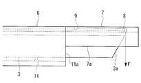
- the endoscope 2 is a direct-view type, but instead, as shown in FIGS. 6A and 6B, the endoscope 2 is tilted with respect to the longitudinal direction. It may be a perspective type in which the observation window 5 is provided on the surface 3a. In the case of the perspective-type endoscope 2, it is not necessary to bend the bending portion 4 at the time of bird's-eye observation of the heart A. A large distance can be secured.
- the insertion portion 3 When cleaning the heart A, as shown in FIG. 6B, instead of operating the bending portion 4, the insertion portion 3 is moved to the proximal end side until the distal end surface 3a does not interfere with the cleaning fluid F ejected from the ejection port 8. Operation to move is performed. Accordingly, the observation range of the heart A can be cleaned with the cleaning fluid F while observing the observation range of the heart A with the endoscope 2. As described above, in the case of the perspective endoscope 2, since the cleaning target is switched by the movement of the insertion portion 3 in the longitudinal direction, the fixing portion 10 may be omitted.
- a rotation restricting portion that restricts the rotation of the insertion portion 3 in the endoscope channel 11 while allowing the insertion portion 3 to move in the longitudinal direction in the endoscope channel 11. It may be provided.
- the rotation restricting portion restricts the rotation of the inserting portion 3 in the endoscope channel 11 so that the inserting portion 3 is held in a posture in which the distal end surface 3a faces the notch 7a.
- the rotation restricting portion includes, for example, a radially projecting protrusion provided on the outer peripheral surface of the insertion portion 3 and a groove that is formed on the inner peripheral surface of the endoscope channel 11 along the longitudinal direction and guides the inserted protrusion. It consists of.
- the protrusion may be provided on the inner peripheral surface of the endoscope channel 11 and the groove may be provided on the outer peripheral surface of the insertion portion 3.
- the sheath body 6 may further be provided with a treatment instrument channel into which the treatment instrument is inserted.
- the treatment instrument channel may be formed completely independently of the fluid channel 9, as shown in FIG. 7, a part of the fluid channel 9 may be used as the treatment instrument channel.
- the sheath body 6 of FIG. 7 includes a treatment instrument insertion port 17 provided on the base end surface of the sheath body 6, a fluid channel 9 extending in the longitudinal direction from the treatment instrument insertion port 17 toward the distal end side, and the fluid channel 9 is further provided with a treatment instrument channel 16 communicating at a midway position 9.
- the fluid channel 9 is formed on the distal end surface of the projecting portion 7 and extends to a treatment instrument opening 18 into which the treatment instrument can project and retract. Thereby, the treatment instrument can be inserted into the pericardial cavity via the treatment instrument insertion port 17, the treatment instrument channel 16, the fluid channel 9 and the treatment instrument opening 18.
- the treatment instrument insertion port 17 and the treatment instrument opening 18 are preferably provided with a valve that prevents the cleaning fluid F from leaking while allowing the treatment instrument to move in the longitudinal direction.
- FIG. 7 shows a guide wire 19 as an example of a treatment instrument.
- the pericardium B is lifted by the guide wire 19 on the distal end side of the projecting portion 7.
- a larger space S can be secured around the area.
- other types of treatment instruments may be used.
- the inner surface of the ejection port 8 is formed perpendicular to the longitudinal direction of the endoscope channel 11, but instead, the inner surface on the proximal end side of the ejection port 8 is As shown in FIG. 8, the base end side may be inclined. By doing in this way, the cleaning fluid F is also injected from the injection port 8 also in the diagonal direction toward the base end side. Therefore, in the state where the bending portion 4 is bent, the cleaning fluid F can be sprayed onto the observation window 5 simultaneously with the heart A to simultaneously clean both the observation range of the heart A and the observation window 5.
- the endoscope 2 and the sheath body 6 are separate from each other. Instead, as shown in FIG. 9, the outer peripheral surface of the insertion portion 3 and the endoscope channel 11 are used.
- the endoscope 2 and the sheath body 6 may be integrally formed by fixing the inner peripheral surfaces of the endoscope 2 and the sheath body 6 to each other.
- the endoscope 2 and the sheath body 6 are arranged so that the distal end surface 3a of the insertion portion 3 is adjacent to the ejection port 8 in the radial direction, and the notch 7a is arranged in a direction in which the bending portion 4 can be bent. Fixed.
- injection port 8 only one injection port 8 is provided, but a plurality of injection ports 8 may be provided instead.
- the plurality of injection ports 8 may be arranged in the longitudinal direction of the protrusion 7 as shown in FIG. 10A, or may be arranged in the circumferential direction of the protrusion 7 as shown in FIG. 10B. .
- a wider range of living tissue can be washed.
- tip part of the insertion part 3 can also be wash
- One fluid channel 9 may be provided for each ejection port 8. By doing in this way, even if any one of the fluid channels 9 or the ejection port 8 is clogged, the observation window 5 and the heart A can be cleaned using the other fluid channel 9 and the ejection port 8.
- one common fluid channel 9 may be provided for the plurality of ejection ports 8.
Landscapes
- Health & Medical Sciences (AREA)
- Life Sciences & Earth Sciences (AREA)
- Surgery (AREA)
- Nuclear Medicine, Radiotherapy & Molecular Imaging (AREA)
- Biomedical Technology (AREA)
- Optics & Photonics (AREA)
- Pathology (AREA)
- Radiology & Medical Imaging (AREA)
- Biophysics (AREA)
- Engineering & Computer Science (AREA)
- Physics & Mathematics (AREA)
- Heart & Thoracic Surgery (AREA)
- Medical Informatics (AREA)
- Molecular Biology (AREA)
- Animal Behavior & Ethology (AREA)
- General Health & Medical Sciences (AREA)
- Public Health (AREA)
- Veterinary Medicine (AREA)
- Endoscopes (AREA)
Abstract
内視鏡シース(1)は、内視鏡チャネル(11)が形成されたシース本体(6)と、内視鏡チャネル(11)の径方向外側において周方向の一部に設けられシース本体(6)の先端から長手方向に延びる突出部(7)と、突出部(7)の先端部に設けられ洗浄流体をシース本体(9)の径方向内方に噴射する噴射口(8)と、噴射口(8)に洗浄流体を供給する流体チャネル(9)とを備え、シース本体(6)の先端側において、内視鏡チャネル(11)を径方向に挟んで噴射口(8)と対向する側が開放されている。
Description
本発明は、内視鏡シースおよび内視鏡システムに関するものである。
従来、洗浄液を噴射する噴射口を先端面に有し、先端面と対向する観察対象組織に洗浄液を噴射することで、観察対象組織に付着した血液等の付着物を洗浄することができる内視鏡が知られている(例えば、特許文献1参照。)。また、内視鏡の先端面に向かって開口する噴射口を有し、噴射口から内視鏡の先端面に洗浄液を噴射することで、先端面の観察窓に付着した付着物を洗浄することができる内視鏡シースが知られている(例えば、特許文献2参照。)。
しかしながら、特許文献1の内視鏡は、観察窓と同一面上に噴射口が設けられているため、観察窓を洗浄することができないという不都合がある。
一方、特許文献2の内視鏡シースは、該内視鏡シースの先端近傍に設けられた噴射口から径方向に洗浄液が噴射される構造となっているため、内視鏡の先端面と対向する観察対象組織を洗浄することができないという不都合がある。特に、心臓と心膜との間の心膜腔内で使用される心嚢内視鏡の場合、内視鏡の側方に位置する心臓を観察するためには、内視鏡シースから内視鏡の先端部を突出させて先端面が心臓を向くように湾曲部を湾曲させる必要がある。このような心嚢内視鏡に特許文献2の内視鏡シースを組み合わせた場合、内視鏡の観察範囲に噴射口からの洗浄液を吹きかけることができず、観察範囲を洗浄することができない。
一方、特許文献2の内視鏡シースは、該内視鏡シースの先端近傍に設けられた噴射口から径方向に洗浄液が噴射される構造となっているため、内視鏡の先端面と対向する観察対象組織を洗浄することができないという不都合がある。特に、心臓と心膜との間の心膜腔内で使用される心嚢内視鏡の場合、内視鏡の側方に位置する心臓を観察するためには、内視鏡シースから内視鏡の先端部を突出させて先端面が心臓を向くように湾曲部を湾曲させる必要がある。このような心嚢内視鏡に特許文献2の内視鏡シースを組み合わせた場合、内視鏡の観察範囲に噴射口からの洗浄液を吹きかけることができず、観察範囲を洗浄することができない。
本発明は、上述した事情に鑑みてなされたものであって、内視鏡の観察窓と内視鏡の側方に位置する観察対象組織の観察範囲の両方を洗浄することができる内視鏡シースおよび内視鏡システムを提供することを目的とする。
上記目的を達成するため、本発明は以下の手段を提供する。
本発明の第1の態様は、内視鏡が挿入される内視鏡チャネルが長手方向に沿って貫通形成された筒状のシース本体と、前記内視鏡チャネルの径方向外側において該内視鏡チャネルの周方向の一部に設けられ、前記内視鏡チャネルの先端開口から突出する前記内視鏡の先端部よりも突出する位置まで前記シース本体の先端から前記長手方向に延びる突出部と、該突出部の先端部に設けられ、前記内視鏡チャネルの先端開口から突出する前記内視鏡の先端部の先端面に向けて洗浄流体を前記シース本体の径方向内方に噴射する噴射口と、前記シース本体および前記突出部に前記長手方向に設けられ前記噴射口に前記洗浄流体を供給する流体チャネルとを備え、前記シース本体の先端側において、前記内視鏡チャネルを径方向に挟んで前記噴射口と対向する側が開放されている内視鏡シースである。
本発明の第1の態様は、内視鏡が挿入される内視鏡チャネルが長手方向に沿って貫通形成された筒状のシース本体と、前記内視鏡チャネルの径方向外側において該内視鏡チャネルの周方向の一部に設けられ、前記内視鏡チャネルの先端開口から突出する前記内視鏡の先端部よりも突出する位置まで前記シース本体の先端から前記長手方向に延びる突出部と、該突出部の先端部に設けられ、前記内視鏡チャネルの先端開口から突出する前記内視鏡の先端部の先端面に向けて洗浄流体を前記シース本体の径方向内方に噴射する噴射口と、前記シース本体および前記突出部に前記長手方向に設けられ前記噴射口に前記洗浄流体を供給する流体チャネルとを備え、前記シース本体の先端側において、前記内視鏡チャネルを径方向に挟んで前記噴射口と対向する側が開放されている内視鏡シースである。
本発明の第1の態様によれば、シース本体の先端側には噴射口を有する突出部が周方向の一部に設けられ、噴射口と対向する側が開放されている。したがって、開放されている部分を観察対象組織に向けてシース本体を配置し、シース本体の内視鏡チャネル内に挿入された内視鏡の先端部を内視鏡チャネルの先端開口から突出部まで突出させることで、観察対象組織を内視鏡で観察することができる。観察対象組織の観察範囲を洗浄したいときには、噴射口と観察対象組織の観察範囲との間に内視鏡が介在しないように内視鏡を配置し、流体チャネルを介して噴射口に洗浄流体を供給することで、噴射口から噴射された洗浄流体を観察対象組織の観察範囲に吹きかけて該観察範囲を洗浄することができる。
また、内視鏡の先端面の観察窓を洗浄したいときには、噴射口と径方向に隣接する位置に内視鏡の先端面を配置し、流体チャネルを介して噴射口に洗浄流体を供給することで、噴射口から内視鏡の先端面へ洗浄流体を吹きかけて観察窓を洗浄することができる。
また、内視鏡の先端面の観察窓を洗浄したいときには、噴射口と径方向に隣接する位置に内視鏡の先端面を配置し、流体チャネルを介して噴射口に洗浄流体を供給することで、噴射口から内視鏡の先端面へ洗浄流体を吹きかけて観察窓を洗浄することができる。
上記第1の態様においては、前記突出部に複数の前記噴射口が設けられていてもよい。
このようにすることで、洗浄流体を広範囲に噴射することができ、内視鏡の先端面および観察対象組織のより広い範囲を洗浄することができる。
このようにすることで、洗浄流体を広範囲に噴射することができ、内視鏡の先端面および観察対象組織のより広い範囲を洗浄することができる。
上記第1の態様においては、前記シース本体の基端部から前記長手方向に延び前記流体チャネルと該流体チャネルの長手方向の途中位置で連通し、処置具が挿入される処置具チャネルを備え、前記流体チャネルが、前記処置具を挿入可能であるとともに、前記突出部の先端面に開口し前記処置具が突没する処置具開口まで延びていてもよい。
このようにすることで、処置具チャネルから流体チャネルに挿入した処置具を突出部の先端の処置具開口から突出させることができる。このように、流体チャネルを処置具用のチャネルとしても使用することで、シース本体の略全長にわたって流体チャネルとは別の処置具チャネルを設ける場合と比べて、シース本体の細径化を図ることができる。
このようにすることで、処置具チャネルから流体チャネルに挿入した処置具を突出部の先端の処置具開口から突出させることができる。このように、流体チャネルを処置具用のチャネルとしても使用することで、シース本体の略全長にわたって流体チャネルとは別の処置具チャネルを設ける場合と比べて、シース本体の細径化を図ることができる。
上記第1の態様においては、前記突出部が、周方向の一部に長手方向に切り欠かれた切欠を有する略部分円筒状であってもよい。
このようにすることで、切欠とは反対側において内視鏡の先端部が突出部によって覆われるので、内視鏡の先端部を周囲の生体組織から保護することができる。
このようにすることで、切欠とは反対側において内視鏡の先端部が突出部によって覆われるので、内視鏡の先端部を周囲の生体組織から保護することができる。
本発明の第2の態様は、上記いずれかに記載の内視鏡シースと、該内視鏡シースの前記内視鏡チャネル内に長手方向に沿って挿入される内視鏡とを備える内視鏡システムである。
上記第2の態様においては、前記内視鏡が、前記内視鏡チャネル内で長手方向に移動可能であってもよい。
このようにすることで、内視鏡の先端面が噴射口と隣接する位置と、内視鏡の先端面が噴射口よりも基端側に配置される位置との間で内視鏡を長手方向に移動させることで、洗浄流体による洗浄対象を観察窓と観察対象組織の観察範囲との間で切り替えることができる。
上記第2の態様においては、前記内視鏡が、前記内視鏡チャネル内で長手方向に移動可能であってもよい。
このようにすることで、内視鏡の先端面が噴射口と隣接する位置と、内視鏡の先端面が噴射口よりも基端側に配置される位置との間で内視鏡を長手方向に移動させることで、洗浄流体による洗浄対象を観察窓と観察対象組織の観察範囲との間で切り替えることができる。
上記第2の態様においては、前記内視鏡の先端が前記噴射口と前記径方向に並ぶ位置に前記内視鏡シースおよび前記内視鏡の前記長手方向の相対位置を規制する位置規制部を備えていてもよい。
このようにすることで、観察窓の洗浄に適した位置に内視鏡の先端面が配置されるように、内視鏡シースおよび内視鏡の相対位置を規制することができる。
このようにすることで、観察窓の洗浄に適した位置に内視鏡の先端面が配置されるように、内視鏡シースおよび内視鏡の相対位置を規制することができる。
上記第2の態様においては、前記内視鏡が、湾曲可能な湾曲部を先端部に備え、前記湾曲部が前記噴射口とは反対側に湾曲するように、前記内視鏡チャネル内における前記内視鏡の長手軸回りの回転を規制する回転規制部を備えていてもよい。
このようにすることで、内視鏡の湾曲部が観察対象組織側に湾曲するように、内視鏡チャネル内における内視鏡の長手軸回りの姿勢を規制することができる。
このようにすることで、内視鏡の湾曲部が観察対象組織側に湾曲するように、内視鏡チャネル内における内視鏡の長手軸回りの姿勢を規制することができる。
上記第2の態様においては、前記内視鏡シースと前記内視鏡とが、一体構造に形成されていてもよい。
このようにすることで、内視鏡に内視鏡シースを取り付ける操作を不要にすることができる。
このようにすることで、内視鏡に内視鏡シースを取り付ける操作を不要にすることができる。
本発明によれば、内視鏡の観察窓と内視鏡の側方に位置する観察対象組織の観察範囲の両方を洗浄することができるという効果を奏する。
以下に、本発明の一実施形態に係る内視鏡シース1および内視鏡システム100について図面を参照して説明する。
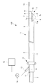
本実施形態に係る内視鏡システム100は、図1に示されるように、内視鏡2と、該内視鏡2が挿入可能な内視鏡チャネル11を有する内視鏡シース1とを備えている。
内視鏡2は、心膜腔内に挿入可能な細径で長尺状の軟性の挿入部3と、該挿入部3の先端部に設けられ少なくとも一方向に湾曲可能な湾曲部4とを備えている。内視鏡2は、挿入部3の長手軸に垂直な先端面3aに観察窓5(図3参照。)が設けられた直視型である。
本実施形態に係る内視鏡システム100は、図1に示されるように、内視鏡2と、該内視鏡2が挿入可能な内視鏡チャネル11を有する内視鏡シース1とを備えている。
内視鏡2は、心膜腔内に挿入可能な細径で長尺状の軟性の挿入部3と、該挿入部3の先端部に設けられ少なくとも一方向に湾曲可能な湾曲部4とを備えている。内視鏡2は、挿入部3の長手軸に垂直な先端面3aに観察窓5(図3参照。)が設けられた直視型である。
内視鏡2の先端部には、対物レンズ(図示略)および撮像素子(図示略)が設けられ、観察窓5に入射した光が対物レンズによって結像され、形成された像が撮像素子によって撮像されるようなっている。あるいは、内視鏡2内に長手方向に沿ってファイババンドルが設けられ、対物レンズによって形成された像がファイババンドルによって内視鏡2の基端部に設けられた撮像素子まで光学的に伝送されるように構成されていてもよい。撮像素子によって取得された画像信号は、電気的にイメージプロセッサに送信され、イメージプロセッサにおいて内視鏡画像に生成され、内視鏡画像がモニタに表示されるようになっている。
内視鏡2は、レーザ光を被写体上で2次元的に走査し、被写体からのレーザ光の反射光を観察窓5を介して受光し、レーザ光の走査位置と反射光の強度とに基づいて被写体の2次元画像を生成する光走査型内視鏡であってもよい。
内視鏡2は、レーザ光を被写体上で2次元的に走査し、被写体からのレーザ光の反射光を観察窓5を介して受光し、レーザ光の走査位置と反射光の強度とに基づいて被写体の2次元画像を生成する光走査型内視鏡であってもよい。
内視鏡シース1は、長手軸を有し両端において開口する円筒状のシース本体6と、シース本体6の先端に接続された該シース本体6の先端から長手方向に突出する突出部7と、突出部7の先端部に設けられ洗浄流体Fを噴射する噴射口8と、噴射口8に洗浄流体Fを供給する流体チャネル9と、内視鏡チャネル11内に配置された挿入部3の位置および姿勢を固定する固定部(位置規制部、回転規制部)10とを備えている。
シース本体6は、生体内の組織形状に沿って湾曲可能な可撓性を有している。シース本体6の内部には、シース本体6の基端面の基端開口から先端面の先端開口11aまで長手軸に沿って貫通する内視鏡チャネル11が形成されている。内視鏡チャネル11は、挿入部3の外径よりも大きな内径を有し、内視鏡チャネル11内で挿入部3の長手方向の移動および長手軸回りの回転が可能となっている。
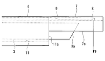
突出部7は、周方向の一部に長手方向に切り欠かれた切欠7aを有する略部分円筒状である。突出部7は、先端開口11aを囲むシース本体6の円環状の先端面の周方向の一部分からシース本体6の長手方向に沿って突出し、シース本体6を先端側から長手方向に見たときに内視鏡チャネル11の径方向外側に配置されている。突出部7は、図2Aに示されるように、先端開口11aから湾曲部4が突出した状態での挿入部3の先端面3aよりも突出する位置まで延びる長さ寸法を有している。
シース本体6の径方向における切欠7aの幅は、湾曲部4の直径よりも大きくなっている。これにより、図1において二点鎖線で示されるように、突出部7内において湾曲部4が切欠7a側に湾曲したときに、挿入部3の先端面3aが切欠7aから径方向へ突出することができるようになっている。図示されている突出部7は、長手方向の全長にわたって略半周を切り欠いた略半円筒状であるが、切欠7aの長さおよび幅は適宜変更可能である。
また、突出部7は、心膜腔内において心膜から受ける心臓側への押圧力に抗して略直線形状を維持可能な剛性を有している。
また、突出部7は、心膜腔内において心膜から受ける心臓側への押圧力に抗して略直線形状を維持可能な剛性を有している。
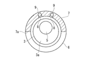
噴射口8は、図3に示されるように、内視鏡チャネル11を間に挟んで切欠7aと内視鏡チャネル11の径方向に対向する位置において突出部7の内面に開口している。噴射口8は、内視鏡チャネル11の中心軸に向かって該内視鏡チャネル11の長手方向に対して垂直に延びる円筒状の内面を有し、切欠7aに向かって内視鏡チャネル11の径方向内方に洗浄流体Fを噴射する。また、噴射口8は、図2Aに示されるように、先端開口11aから湾曲部4が突出した状態で挿入部3の先端面3aと径方向に隣接する位置に設けられている。
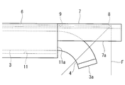
したがって、図2Aに示されるように、噴射口8と径方向に隣接する位置に挿入部3の先端面3aを配置することで、噴射口8から噴射された洗浄流体Fを先端面3aに吹きかけて観察窓5を洗浄することができる。また、図2Bに示されるように、図2Aの状態から湾曲部4を切欠7a側に湾曲させて湾曲部4の先端側に洗浄流体Fが通過するスペースを形成することで、噴射口8から噴射された洗浄流体Fを内視鏡チャネル11および切欠7aを介してシース本体6の側方に位置する生体組織に吹きかけて該生体組織を洗浄することができる。
流体チャネル9は、シース本体6の基端部に設けられた供給口13から噴射口8までシース本体6の側壁および突出部7に長手方向に形成されている。供給口13は、洗浄流体Fを保持する流体源15とポンプ14を介して接続され、ポンプ14の作動によって流体源15から供給口13および流体チャネル9を介して噴射口8まで洗浄流体Fが供給される。洗浄流体Fは、生理食塩水のような液体であってもよく、生体組織および観察窓5上の血液等の付着物を吹き飛ばす気体であってもよい。
固定部10は、内視鏡チャネル11内に挿入された挿入部3の長手方向の途中位置を、シース本体6に対して固定する。このような固定部10は、例えば、図4に示されるように、シース本体6の周方向に間隔をあけて設けられ、シース本体6の外側から内視鏡チャネル11内へシース本体6の側壁を径方向に貫通する複数の止めねじ10aを備える。止めねじ10aを締めることで、シース本体6に対して挿入部3が進退および回転しないように、シース本体6に対する挿入部3の長手方向の位置および回転を規制することができる。挿入部3に接触する止めねじ10aの先端部は、挿入部3の外面を保護するためにゴムのような弾性材で被覆されていてもよい。
次に、このように構成された内視鏡システム100の作用について説明する。
本実施形態に係る内視鏡システム100を使用して心臓Aを観察するためには、まず、内視鏡2の挿入部3をシース本体6の内視鏡チャネル11内に挿入し、図2Aに示されるように、湾曲部4が真っ直ぐに延びた状態で挿入部3の先端面3aが噴射口8と径方向に隣接するように内視鏡チャネル11内での挿入部3の長手方向における位置を決定する。また、図2Bに示されるように、湾曲部4が噴射口8とは反対側(切欠7a側)に湾曲するように、内視鏡チャネル11内での挿入部3の長手軸回りの姿勢を決定する。次に、挿入部3を決定した位置および姿勢に固定部10によってシース本体6に対して固定する。
本実施形態に係る内視鏡システム100を使用して心臓Aを観察するためには、まず、内視鏡2の挿入部3をシース本体6の内視鏡チャネル11内に挿入し、図2Aに示されるように、湾曲部4が真っ直ぐに延びた状態で挿入部3の先端面3aが噴射口8と径方向に隣接するように内視鏡チャネル11内での挿入部3の長手方向における位置を決定する。また、図2Bに示されるように、湾曲部4が噴射口8とは反対側(切欠7a側)に湾曲するように、内視鏡チャネル11内での挿入部3の長手軸回りの姿勢を決定する。次に、挿入部3を決定した位置および姿勢に固定部10によってシース本体6に対して固定する。
次に、固定部10によって一体化されたシース本体6および挿入部3を、体外から心膜腔内まで予め配置された筒状のトロッカーを介して心膜腔内へ挿入する。心膜腔内において、図5に示されるように、突出部7が心膜B側に配置されるようにシース本体6を配置することで、高い剛性を有する突出部7によって心膜Bが持ち上げられて心膜Bが心臓Aから離れた位置に保持され、挿入部3の先端面3aの周囲に空間Sが確保される。この状態で湾曲部4を切欠7a側へ湾曲させることで、挿入部3の先端面3aの観察窓5を観察対象組織である心臓Aと対向するように配置して心臓Aを俯瞰観察することができる。
心膜腔内での観察中に観察窓5に血液等の付着物が付着して観察窓5の洗浄が必要となったとき、術者は、図5において実線で示されるように、湾曲部4を直線状に戻し、ポンプ14を作動させる。これにより、噴射口8から、該噴射口8の正面に位置する挿入部3の先端面3aに向かって洗浄流体Fが噴射され、洗浄流体Fによって観察窓5が洗浄される。
また、心膜腔内での観察中に心臓Aの観察範囲に血液等の付着物が付着して観察範囲の洗浄が必要となったとき、術者は、図5において二点鎖線で示されるように、湾曲部4を切欠7a側へ湾曲させることにより噴射口8から噴射される洗浄流体Fの経路から湾曲部4を退避させ、ポンプ14を作動させる。これにより、噴射口8から噴射された洗浄流体Fは、挿入部3の先端部によって遮られることなく、切欠7aを介して心臓Aの観察範囲へ噴射され、洗浄流体Fによって観察範囲が洗浄される。このときに、観察窓5は心臓Aに向けられているので、洗浄される心臓Aの観察範囲を内視鏡2によって観察することができる。
このように、本実施形態によれば、噴射口8が、内視鏡チャネル11の先端開口11aから湾曲部4を突出させた状態で挿入部3の先端面3aと径方向に並ぶ位置に設けられている。さらに、内視鏡チャネル11を径方向に挟み噴射口8と対向する側に設けられた切欠7aにより、シース本体6の先端側は心臓A側において開放されるように形成されている。これにより、湾曲部4の心臓A側への湾曲によって観察される観察範囲を噴射口8から噴射された洗浄流体Fによって効率的に洗浄することができるという利点がある。また、湾曲部4を、真っ直ぐの状態と湾曲した状態と間で動作させるだけの簡単な操作で、洗浄対象を観察窓5と心臓Aの観察範囲との間で切り替えることができるという利点がある。
本実施形態においては、内視鏡2が直視型であることとしたが、これに代えて、図6Aおよび図6Bに示されるように、内視鏡2が、長手方向に対して傾斜する先端面3aに観察窓5が設けられた斜視型であってもよい。
斜視型の内視鏡2の場合、心臓Aの俯瞰観察の際に湾曲部4を湾曲させる必要がないので、直視型の内視鏡2と比べて、心臓Aと先端面3aとの間により大きな距離を確保することができる。
斜視型の内視鏡2の場合、心臓Aの俯瞰観察の際に湾曲部4を湾曲させる必要がないので、直視型の内視鏡2と比べて、心臓Aと先端面3aとの間により大きな距離を確保することができる。
心臓Aの洗浄時には、図6Bに示されるように、湾曲部4の操作に代えて、先端面3aが噴射口8から噴射される洗浄流体Fに干渉しない位置まで挿入部3を基端側へ移動させる操作が行われる。これにより、心臓Aの観察範囲を内視鏡2によって観察しながら該心臓Aの観察範囲を洗浄流体Fによって洗浄することができる。
このように、斜視型の内視鏡2の場合、洗浄対象の切り替えが挿入部3の長手方向の移動によって行われるため、固定部10は省略されてもよい。
このように、斜視型の内視鏡2の場合、洗浄対象の切り替えが挿入部3の長手方向の移動によって行われるため、固定部10は省略されてもよい。
あるいは、固定部10に代えて、内視鏡チャネル11内での挿入部3の長手方向の移動を許容しつつ、内視鏡チャネル11内での挿入部3の回転を規制する回転規制部が設けられていてもよい。回転規制部は、先端面3aを切欠7a側に向けた姿勢に挿入部3が保持されるように、内視鏡チャネル11内での挿入部3の回転を規制する。回転規制部は、例えば、挿入部3の外周面に設けられた径方向に突出する突起と、内視鏡チャネル11の内周面に長手方向に沿って形成され挿入された突起を案内する溝とから構成される。突起が内視鏡チャネル11の内周面に設けられ、溝が挿入部3の外周面に設けられていてもよい。
本実施形態においては、シース本体6に、処置具が挿入される処置具チャネルがさらに設けられていてもよい。
処置具チャネルは、流体チャネル9とは完全に独立に形成されていてもよいが、図7に示されるように、流体チャネル9の一部を処置具チャネルとして利用してもよい。
処置具チャネルは、流体チャネル9とは完全に独立に形成されていてもよいが、図7に示されるように、流体チャネル9の一部を処置具チャネルとして利用してもよい。
図7のシース本体6には、該シース本体6の基端面に設けられた処置具挿入口17と、該処置具挿入口17から先端側に向かって長手方向に延び流体チャネル9と該流体チャネル9の途中位置で連通する処置具チャネル16とがさらに設けられている。流体チャネル9は、突出部7の先端面に形成され処置具が突没可能な処置具開口18まで延びている。これにより、処置具挿入口17、処置具チャネル16、流体チャネル9および処置具開口18を介して、心膜腔内に処置具を挿入することができる。処置具挿入口17および処置具開口18には、処置具の長手方向の移動を許容しつつ洗浄流体Fの漏れを阻止する弁が設けられていることが好ましい。
図7には、処置具の一例としてガイドワイヤ19が示されている。図7に示されるように、突出部7の先端からガイドワイヤ19を突出させることにより、突出部7の先端側においても、心膜Bをガイドワイヤ19によって持ち上げて、挿入部3の先端面3aの周囲により大きな空間Sを確保することができる。ガイドワイヤ19に代えて、他の種類の処置具を使用してもよい。
本実施形態においては、噴射口8の内面が、内視鏡チャネル11の長手方向に対して垂直に形成されていることとしたが、これに代えて、噴射口8の基端側の内面が、図8に示されるように、基端側に傾斜していてもよい。
このようにすることで、噴射口8からは基端側に向かって斜め方向にも洗浄流体Fが噴射される。したがって、湾曲部4を湾曲させた状態で、心臓Aと同時に観察窓5にも洗浄流体Fを吹きかけて心臓Aの観察範囲と観察窓5の両方を同時に洗浄することができる。
このようにすることで、噴射口8からは基端側に向かって斜め方向にも洗浄流体Fが噴射される。したがって、湾曲部4を湾曲させた状態で、心臓Aと同時に観察窓5にも洗浄流体Fを吹きかけて心臓Aの観察範囲と観察窓5の両方を同時に洗浄することができる。
本実施形態においては、内視鏡2とシース本体6とが別体であることとしたが、これに代えて、図9に示されるように、挿入部3の外周面と内視鏡チャネル11の内周面とが互いに固定されることにより、内視鏡2とシース本体6とが一体構造に形成されていてもよい。内視鏡2とシース本体6は、挿入部3の先端面3aが噴射口8と径方向に隣接するように、また、湾曲部4の湾曲可能な方向に切欠7aが配置されるように、固定される。
このようにすることで、挿入部3とシース本体6との固定作業を不要にすることができる。また、内視鏡チャネル11内に、該内視鏡チャネル11内での挿入部3の進退および回転を可能にするためのクリアランスを確保する必要がないため、シース本体6の細径化を図ることができる。
本実施形態においては、噴射口8が1つのみ設けられていることとしたが、これに代えて、複数の噴射口8が設けられていてもよい。複数の噴射口8は、図10Aに示されるように、突出部7の長手方向に配列されていてもよく、図10Bに示されるように、突出部7の周方向に配列されていてもよい。
このように複数の噴射口8を設けることによって、より広範囲の生体組織を洗浄することができる。また、図10Aのように複数の噴射口8が長手方向に配列している場合には、挿入部3の先端部の側面に付着した付着物も洗浄することができる。
このように複数の噴射口8を設けることによって、より広範囲の生体組織を洗浄することができる。また、図10Aのように複数の噴射口8が長手方向に配列している場合には、挿入部3の先端部の側面に付着した付着物も洗浄することができる。
流体チャネル9は、各噴射口8に対して1本ずつ設けられていてもよい。このようにすることで、いずれかの流体チャネル9または噴射口8が詰まったとしても、他の流体チャネル9および噴射口8を使用して観察窓5および心臓Aの洗浄を行うことができる。
あるいは、複数の噴射口8に対して共通の1本の流体チャネル9が設けられていてもよい。
あるいは、複数の噴射口8に対して共通の1本の流体チャネル9が設けられていてもよい。
1 内視鏡シース
2 内視鏡
3 挿入部
3a 先端面
4 湾曲部
5 観察窓
6 シース本体
7 突出部
7a 切欠
8 噴射口
9 流体チャネル
10 固定部(位置規制部、回転規制部)
11 内視鏡チャネル
13 供給口
14 ポンプ
15 流体源
16 処置具チャネル
17 処置具挿入口
18 処置具開口
19 ガイドワイヤ(処置具)
100 内視鏡システム
F 洗浄流体
A 心臓
B 心膜
2 内視鏡
3 挿入部
3a 先端面
4 湾曲部
5 観察窓
6 シース本体
7 突出部
7a 切欠
8 噴射口
9 流体チャネル
10 固定部(位置規制部、回転規制部)
11 内視鏡チャネル
13 供給口
14 ポンプ
15 流体源
16 処置具チャネル
17 処置具挿入口
18 処置具開口
19 ガイドワイヤ(処置具)
100 内視鏡システム
F 洗浄流体
A 心臓
B 心膜
Claims (9)
- 内視鏡が挿入される内視鏡チャネルが長手方向に沿って貫通形成された筒状のシース本体と、
前記内視鏡チャネルの径方向外側において該内視鏡チャネルの周方向の一部に設けられ、前記内視鏡チャネルの先端開口から突出する前記内視鏡の先端部よりも突出する位置まで前記シース本体の先端から前記長手方向に延びる突出部と、
該突出部の先端部に設けられ、前記内視鏡チャネルの先端開口から突出する前記内視鏡の先端部の先端面に向けて洗浄流体を前記シース本体の径方向内方に噴射する噴射口と、
前記シース本体および前記突出部に前記長手方向に設けられ前記噴射口に前記洗浄流体を供給する流体チャネルとを備え、
前記シース本体の先端側において、前記内視鏡チャネルを径方向に挟んで前記噴射口と対向する側が開放されている内視鏡シース。 - 前記突出部に複数の前記噴射口が設けられている請求項1に記載の内視鏡シース。
- 前記シース本体の基端部から前記長手方向に延び前記流体チャネルと該流体チャネルの長手方向の途中位置で連通し、処置具が挿入される処置具チャネルを備え、
前記流体チャネルが、前記処置具を挿入可能であるとともに、前記突出部の先端に開口し前記処置具が突没する処置具開口まで延びる請求項1または請求項2に記載の内視鏡シース。 - 前記突出部が、周方向の一部に長手方向に切り欠かれた切欠を有する略部分円筒状である請求項1から請求項3のいずれかに記載の内視鏡シース。
- 請求項1から請求項4のいずれかに記載に内視鏡シースと、
該内視鏡シースの前記内視鏡チャネル内に長手方向に沿って挿入される内視鏡とを備える内視鏡システム。 - 前記内視鏡が、前記内視鏡チャネル内で長手方向に移動可能である請求項5に記載の内視鏡システム。
- 前記内視鏡の先端が前記噴射口と前記径方向に並ぶ位置に前記内視鏡シースおよび前記内視鏡の前記長手方向の相対位置を規制する位置規制部を備える請求項6に記載の内視鏡システム。
- 前記内視鏡が、湾曲可能な湾曲部を先端部に備え、
前記湾曲部が前記噴射口とは反対側に湾曲するように、前記内視鏡チャネル内における前記内視鏡の長手軸回りの回転を規制する回転規制部を備える請求項6または請求項7に記載の内視鏡システム。 - 前記内視鏡シースと前記内視鏡とが、一体構造に形成されている請求項5に記載の内視鏡システム。
Priority Applications (2)
| Application Number | Priority Date | Filing Date | Title |
|---|---|---|---|
| PCT/JP2017/011407 WO2018173145A1 (ja) | 2017-03-22 | 2017-03-22 | 内視鏡シースおよび内視鏡システム |
| US16/569,738 US20200015663A1 (en) | 2017-03-22 | 2019-09-13 | Endoscope sheath and endoscope system |
Applications Claiming Priority (1)
| Application Number | Priority Date | Filing Date | Title |
|---|---|---|---|
| PCT/JP2017/011407 WO2018173145A1 (ja) | 2017-03-22 | 2017-03-22 | 内視鏡シースおよび内視鏡システム |
Related Child Applications (1)
| Application Number | Title | Priority Date | Filing Date |
|---|---|---|---|
| US16/569,738 Continuation US20200015663A1 (en) | 2017-03-22 | 2019-09-13 | Endoscope sheath and endoscope system |
Publications (1)
| Publication Number | Publication Date |
|---|---|
| WO2018173145A1 true WO2018173145A1 (ja) | 2018-09-27 |
Family
ID=63585062
Family Applications (1)
| Application Number | Title | Priority Date | Filing Date |
|---|---|---|---|
| PCT/JP2017/011407 Ceased WO2018173145A1 (ja) | 2017-03-22 | 2017-03-22 | 内視鏡シースおよび内視鏡システム |
Country Status (2)
| Country | Link |
|---|---|
| US (1) | US20200015663A1 (ja) |
| WO (1) | WO2018173145A1 (ja) |
Cited By (2)
| Publication number | Priority date | Publication date | Assignee | Title |
|---|---|---|---|---|
| CN114727743A (zh) * | 2019-05-29 | 2022-07-08 | 史赛克公司 | 用于术中手术镜清洁的系统和方法 |
| JP2023502002A (ja) * | 2019-11-04 | 2023-01-20 | ガルフ メディカル テクノロジーズ | 手術用具のための洗浄装置 |
Families Citing this family (5)
| Publication number | Priority date | Publication date | Assignee | Title |
|---|---|---|---|---|
| WO2020163449A1 (en) * | 2019-02-05 | 2020-08-13 | Canon U.S.A., Inc. | Endoscope observation window cleaning |
| CN112587078A (zh) * | 2020-12-29 | 2021-04-02 | 泰州市高港中医院 | 一种尿道膀胱鏡系统、尿道膀胱镜鏡鞘及闭孔器 |
| JP7787517B2 (ja) * | 2022-03-11 | 2025-12-17 | 国立大学法人 長崎大学 | 硬性内視鏡のカバーおよび内視鏡ユニット |
| CN116784785B (zh) * | 2023-08-24 | 2023-11-10 | 湖南省华芯医疗器械有限公司 | 一种内窥镜清洗组件、前端组件及内窥镜 |
| CN120189051B (zh) * | 2025-03-04 | 2025-09-09 | 安徽贝科邦生物科技有限公司 | 成像元件清洁装置及其成像系统 |
Citations (2)
| Publication number | Priority date | Publication date | Assignee | Title |
|---|---|---|---|---|
| JPH0681501U (ja) * | 1993-03-16 | 1994-11-22 | 嗣郎 坂本 | 硬性内視鏡の洗浄具 |
| JP3186191U (ja) * | 2013-07-11 | 2013-09-19 | 国立大学法人 長崎大学 | 硬性内視鏡用の洗浄装置 |
-
2017
- 2017-03-22 WO PCT/JP2017/011407 patent/WO2018173145A1/ja not_active Ceased
-
2019
- 2019-09-13 US US16/569,738 patent/US20200015663A1/en not_active Abandoned
Patent Citations (2)
| Publication number | Priority date | Publication date | Assignee | Title |
|---|---|---|---|---|
| JPH0681501U (ja) * | 1993-03-16 | 1994-11-22 | 嗣郎 坂本 | 硬性内視鏡の洗浄具 |
| JP3186191U (ja) * | 2013-07-11 | 2013-09-19 | 国立大学法人 長崎大学 | 硬性内視鏡用の洗浄装置 |
Cited By (5)
| Publication number | Priority date | Publication date | Assignee | Title |
|---|---|---|---|---|
| CN114727743A (zh) * | 2019-05-29 | 2022-07-08 | 史赛克公司 | 用于术中手术镜清洁的系统和方法 |
| JP2022534590A (ja) * | 2019-05-29 | 2022-08-02 | ストライカー コーポレイション | 術中の外科用スコープ洗浄のシステムと方法 |
| JP7635159B2 (ja) | 2019-05-29 | 2025-02-25 | ストライカー コーポレイション | 術中の外科用スコープ洗浄のシステムと方法 |
| JP2023502002A (ja) * | 2019-11-04 | 2023-01-20 | ガルフ メディカル テクノロジーズ | 手術用具のための洗浄装置 |
| JP7664241B2 (ja) | 2019-11-04 | 2025-04-17 | ガルフ メディカル テクノロジーズ | 手術用具のための洗浄装置システム |
Also Published As
| Publication number | Publication date |
|---|---|
| US20200015663A1 (en) | 2020-01-16 |
Similar Documents
| Publication | Publication Date | Title |
|---|---|---|
| WO2018173145A1 (ja) | 内視鏡シースおよび内視鏡システム | |
| US12075977B2 (en) | Endoscope deflection using a distal folding mechanism | |
| JP6723942B2 (ja) | 内視鏡 | |
| JP3785908B2 (ja) | 内視鏡の観察窓洗浄装置 | |
| US10028642B2 (en) | Endoscope | |
| JP6050211B2 (ja) | 内視鏡 | |
| CN116369831B (zh) | 内窥镜 | |
| JP5329604B2 (ja) | 内視鏡用流体噴射ノズルユニット及び内視鏡 | |
| JP5172469B2 (ja) | 内視鏡 | |
| WO2017183366A1 (ja) | 器具挿入補助具 | |
| JP5665650B2 (ja) | 内視鏡 | |
| KR102025220B1 (ko) | 관절용 내시경 | |
| JP5389721B2 (ja) | 内視鏡用フード | |
| JP5501603B2 (ja) | 内視鏡 | |
| JP4596141B2 (ja) | 超音波内視鏡 | |
| JP5297901B2 (ja) | 内視鏡挿入部の先端部構造 | |
| JP7216226B2 (ja) | 内視鏡 | |
| JP2010063721A (ja) | 内視鏡用フード | |
| JP5514077B2 (ja) | 内視鏡用先端フード及び内視鏡システム | |
| JP3293458B2 (ja) | 内視鏡の流体噴射装置 | |
| JP3989742B2 (ja) | 副送水機能を有する内視鏡 | |
| JP3849218B2 (ja) | 内視鏡用フード | |
| JP4297484B2 (ja) | 内視鏡先端面洗浄用ノズル及び内視鏡 | |
| JP5771507B2 (ja) | 内視鏡用キャップ及び内視鏡ユニット | |
| JP4010797B2 (ja) | 内視鏡 |
Legal Events
| Date | Code | Title | Description |
|---|---|---|---|
| 121 | Ep: the epo has been informed by wipo that ep was designated in this application |
Ref document number: 17901434 Country of ref document: EP Kind code of ref document: A1 |
|
| NENP | Non-entry into the national phase |
Ref country code: DE |
|
| 122 | Ep: pct application non-entry in european phase |
Ref document number: 17901434 Country of ref document: EP Kind code of ref document: A1 |
|
| NENP | Non-entry into the national phase |
Ref country code: JP |