WO2018168535A1 - 極低温冷凍機 - Google Patents
極低温冷凍機 Download PDFInfo
- Publication number
- WO2018168535A1 WO2018168535A1 PCT/JP2018/008135 JP2018008135W WO2018168535A1 WO 2018168535 A1 WO2018168535 A1 WO 2018168535A1 JP 2018008135 W JP2018008135 W JP 2018008135W WO 2018168535 A1 WO2018168535 A1 WO 2018168535A1
- Authority
- WO
- WIPO (PCT)
- Prior art keywords
- stage
- radiation shield
- cylinder
- insertion hole
- cryogenic refrigerator
- Prior art date
- Legal status (The legal status is an assumption and is not a legal conclusion. Google has not performed a legal analysis and makes no representation as to the accuracy of the status listed.)
- Ceased
Links
Images

Classifications
-
- F—MECHANICAL ENGINEERING; LIGHTING; HEATING; WEAPONS; BLASTING
- F25—REFRIGERATION OR COOLING; COMBINED HEATING AND REFRIGERATION SYSTEMS; HEAT PUMP SYSTEMS; MANUFACTURE OR STORAGE OF ICE; LIQUEFACTION SOLIDIFICATION OF GASES
- F25B—REFRIGERATION MACHINES, PLANTS OR SYSTEMS; COMBINED HEATING AND REFRIGERATION SYSTEMS; HEAT PUMP SYSTEMS
- F25B9/00—Compression machines, plants or systems, in which the refrigerant is air or other gas of low boiling point
- F25B9/14—Compression machines, plants or systems, in which the refrigerant is air or other gas of low boiling point characterised by the cycle used, e.g. Stirling cycle
-
- F—MECHANICAL ENGINEERING; LIGHTING; HEATING; WEAPONS; BLASTING
- F25—REFRIGERATION OR COOLING; COMBINED HEATING AND REFRIGERATION SYSTEMS; HEAT PUMP SYSTEMS; MANUFACTURE OR STORAGE OF ICE; LIQUEFACTION SOLIDIFICATION OF GASES
- F25B—REFRIGERATION MACHINES, PLANTS OR SYSTEMS; COMBINED HEATING AND REFRIGERATION SYSTEMS; HEAT PUMP SYSTEMS
- F25B9/00—Compression machines, plants or systems, in which the refrigerant is air or other gas of low boiling point
- F25B9/14—Compression machines, plants or systems, in which the refrigerant is air or other gas of low boiling point characterised by the cycle used, e.g. Stirling cycle
- F25B9/145—Compression machines, plants or systems, in which the refrigerant is air or other gas of low boiling point characterised by the cycle used, e.g. Stirling cycle pulse-tube cycle
-
- F—MECHANICAL ENGINEERING; LIGHTING; HEATING; WEAPONS; BLASTING
- F25—REFRIGERATION OR COOLING; COMBINED HEATING AND REFRIGERATION SYSTEMS; HEAT PUMP SYSTEMS; MANUFACTURE OR STORAGE OF ICE; LIQUEFACTION SOLIDIFICATION OF GASES
- F25B—REFRIGERATION MACHINES, PLANTS OR SYSTEMS; COMBINED HEATING AND REFRIGERATION SYSTEMS; HEAT PUMP SYSTEMS
- F25B2309/00—Gas cycle refrigeration machines
- F25B2309/14—Compression machines, plants or systems characterised by the cycle used
- F25B2309/1406—Pulse-tube cycles with pulse tube in co-axial or concentric geometrical arrangements
-
- F—MECHANICAL ENGINEERING; LIGHTING; HEATING; WEAPONS; BLASTING
- F25—REFRIGERATION OR COOLING; COMBINED HEATING AND REFRIGERATION SYSTEMS; HEAT PUMP SYSTEMS; MANUFACTURE OR STORAGE OF ICE; LIQUEFACTION SOLIDIFICATION OF GASES
- F25B—REFRIGERATION MACHINES, PLANTS OR SYSTEMS; COMBINED HEATING AND REFRIGERATION SYSTEMS; HEAT PUMP SYSTEMS
- F25B2309/00—Gas cycle refrigeration machines
- F25B2309/14—Compression machines, plants or systems characterised by the cycle used
- F25B2309/1413—Pulse-tube cycles characterised by performance, geometry or theory
-
- F—MECHANICAL ENGINEERING; LIGHTING; HEATING; WEAPONS; BLASTING
- F25—REFRIGERATION OR COOLING; COMBINED HEATING AND REFRIGERATION SYSTEMS; HEAT PUMP SYSTEMS; MANUFACTURE OR STORAGE OF ICE; LIQUEFACTION SOLIDIFICATION OF GASES
- F25D—REFRIGERATORS; COLD ROOMS; ICE-BOXES; COOLING OR FREEZING APPARATUS NOT OTHERWISE PROVIDED FOR
- F25D19/00—Arrangement or mounting of refrigeration units with respect to devices or objects to be refrigerated, e.g. infrared detectors
- F25D19/006—Thermal coupling structure or interface
Definitions
- the present invention relates to a cryogenic refrigerator that generates cold by expanding high-pressure refrigerant gas.
- a Gifford-McMahon (GM) refrigerator is known as an example of a refrigerator that generates a cryogenic temperature.
- the GM refrigerator changes the volume of the expansion space by reciprocating the displacer in the cylinder.
- the refrigerant gas expands in the expansion space by selectively connecting the expansion space, the discharge side of the compressor, and the intake side in response to the volume change.
- Patent Document 1 proposes a multistage cryogenic refrigerator having a plurality of stages of cooling units.
- Multi-stage cryogenic refrigerators generally have a refrigeration capacity for the second and subsequent stages and are easily affected by radiant heat from the surroundings, and therefore include a radiation shield for shielding radiant heat.
- the present invention has been made in view of such circumstances, and an object thereof is to improve the cooling performance of a multistage cryogenic refrigerator.
- a cryogenic refrigerator includes a first cylinder and a second cylinder connected in series, and a first cylinder provided at an end of the first cylinder on the second cylinder side.
- the first cooling stage is cooled to the first cooling temperature by supplying the working gas to the inside of the first cylinder and the second cylinder, inflated and exhausted to the outside, and the second cooling stage from the first cooling temperature.
- a cryogenic refrigerator that cools to a second cooling temperature that is also low temperature, a second cooling stage that houses the second cooling stage and shields radiant heat from the outside to the second stage, and a second cooling stage And a temperature sensor that detects the temperature of the second cooling stage.
- the radiation shield is formed with an insertion hole through which the output cable of the temperature sensor is drawn out from the radiation shield. The insertion hole directly receives the radiant heat entering from the outside of the radiation shield into the second cooling stage. It is configured not to.
- the cryogenic refrigerator includes a first cylinder and a second cylinder connected in series, a first cooling stage provided at an end of the first cylinder on the second cylinder side, and a first cylinder of the second cylinder. And a second cooling stage provided at the opposite end.
- the first cooling stage is cooled to the first cooling temperature by supplying the working gas to the inside of the first cylinder and the second cylinder, inflated and exhausted to the outside, and the second cooling stage from the first cooling temperature.
- a cryogenic refrigerator that cools to a second cooling temperature that is also low temperature, a second cooling stage that houses the second cooling stage and shields radiant heat from the outside to the second stage, and a second cooling stage And a temperature sensor that detects the temperature of the second cooling stage.
- the radiation shield is formed with an insertion hole through which the output cable of the temperature sensor is drawn out from the radiation shield, and the cryogenic refrigerator further attempts to directly irradiate the second cooling stage through the insertion hole.
- a shielding member for shielding radiant heat is provided.
- the cooling performance of a multistage cryogenic refrigerator can be improved.
- FIGS. 2A and 2B are schematic views showing the cable insertion hole and its periphery. It is a schematic diagram which shows the cable penetration hole of the cryogenic refrigerator concerning a modification, and its periphery. It is a schematic diagram which shows the cable penetration hole of the cryogenic refrigerator which concerns on another modification, and its periphery. It is a schematic diagram which shows the cable penetration hole of the cryogenic refrigerator which concerns on another modification, and its periphery.
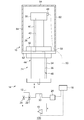
- FIG. 1 is a schematic diagram showing a cryogenic refrigerator 100 according to an embodiment.
- the cryogenic refrigerator 100 is a Gifford McMahon refrigerator (GM refrigerator).
- the cryogenic refrigerator 100 is a two-stage cryogenic refrigerator, and achieves a lower temperature by combining two cooling units in series as will be described later.
- the cryogenic refrigerator 100 includes a compressor 10, a pipe 12, an expander 14, a radiation shield 16, and a control device 18.
- the compressor 10 compresses the low-pressure refrigerant gas returning from the expander 14 and supplies the compressed high-pressure refrigerant gas to the expander 14.
- the pipe 12 connects the compressor 10 and the expander 14.
- the pipe 12 is provided with a high pressure valve 20 and a low pressure valve 22 in parallel.
- the high-pressure working gas is supplied from the compressor 10 to the compressor 10 through the high-pressure valve 20 and the pipe 12.
- the low-pressure working gas is exhausted to the compressor 10 through the pipe 12 and the low-pressure valve 22.
- the refrigerant gas for example, helium gas can be used. Nitrogen gas or other gas may be used as the refrigerant gas.
- the expander 14 expands the high-pressure refrigerant gas supplied from the compressor 10 to generate cold.
- the expander 14 includes a first-stage cooling unit 24, a two-stage cooling unit 26, a drive motor 28, a coupling mechanism 30, and a temperature sensor 48.
- the single-stage cooling unit 24 includes a single-stage 32, a single-stage cylinder 34, and a single-stage displacer 36.
- the two-stage cooling unit 26 includes a two-stage stage 38, a two-stage cylinder 40, and a two-stage displacer 42.
- the first stage cooling unit 24 and the second stage cooling unit 26 are connected in series.
- the direction in which the first-stage cylinder 34 and the second-stage cylinder 40 extend will be referred to as the axial direction, and the side where the second-stage cylinder 40 is provided with respect to the first-stage cylinder 34 in the axial direction will be described as the upper side.
- the axial direction also coincides with the direction in which the first stage displacer 36 and the second stage displacer 42 move.
- the direction orthogonal to the axial direction will be referred to as the radial direction, and the side far from the first stage displacer 36 and the second stage displacer 42 in the radial direction will be described as the inner side.
- the first-stage cylinder 34 and the second-stage cylinder 40 are coaxially connected in series to form one cylinder member 44.
- the single-stage displacer 36 and the two-stage displacer 42 are coaxially connected in series to form one displacer member 46.
- the cylinder member 44 is a hollow airtight container that accommodates the displacer member 46, and guides the reciprocating movement of the displacer member 46 in the axial direction.
- the first stage 32 is an annular member and is fixed to the first stage cylinder 34 so as to surround the upper end of the first stage cylinder 34.
- the second stage 38 is fixed to the upper end of the second stage cylinder 40 so as to surround the upper end of the second stage cylinder 40.
- the second stage 38 is cooled to a lower temperature than the first stage 32.
- the second stage 38 is cooled to about 2K to 10K, for example, and the first stage 32 is cooled to about 30K to 80K, for example.
- the first stage 32 and the second stage 38 are formed of a material having high thermal conductivity such as aluminum or copper.
- the temperature sensor 48 is a temperature sensor for measuring the temperature of the second stage 38 and is attached to the second stage 38.
- the temperature sensor 48 detects the temperature of the second stage 38 at a predetermined cycle, and the detected value is output via the output cable 50.
- the temperature sensor 48 is connected to the control device 18 by the output cable 50, and the detected value is output to the control device 18.
- the drive motor 28 is connected to the displacer member 46 through the connection mechanism 30.
- the connection mechanism 30 includes, for example, a Scotch yoke mechanism.
- the displacer member 46 reciprocates integrally in the axial direction by the drive motor 28 and the coupling mechanism 30.
- the coupling mechanism 30 is coupled to the high pressure valve 20 and the low pressure valve 22 so as to selectively switch between opening of the high pressure valve 20 and opening of the low pressure valve 22 in conjunction with the reciprocating motion. That is, the supply and exhaust of the working gas can be switched in conjunction with the reciprocating motion of the displacer member 46.
- the control device 18 controls the compressor 10 and the drive motor 28.
- the control device 18 controls the pressure difference between the high pressure and the low pressure of the compressor 10 to a target pressure.
- the radiation shield 16 accommodates the two-stage cylinder 40 and the two-stage stage 38 and suppresses radiant heat from the surroundings from entering the two-stage stage 38.
- the radiation shield 16 is formed of a material having high thermal conductivity such as aluminum or copper. In order to reflect radiant heat, the outer surface of the radiation shield 16 may be subjected to gloss plating.
- the radiation shield 16 includes a first radiation shield 62 and a second radiation shield 64.
- the first radiation shield 62 is a disk-shaped member and surrounds the first stage 32.
- the first radiation shield 62 may be formed integrally with the first stage 32 or may be formed separately from the first stage 32 and then coupled to the first stage 32.
- the first radiation shield 62 may be a flange for connecting the first stage 32 formed integrally with the first stage 32 to the object to be cooled.
- the second radiation shield 64 has a bottomed cup shape in which the cylindrical portion 52 and the bottom portion 54 are integrally formed.
- the second radiation shield 64 is fixed to the first radiation shield 62 so that the opening is closed by the first radiation shield 62 with the bottom 54 facing up.
- the first radiation shield 62 and the second radiation shield 64 are cooled by the first stage 32 because they are thermally connected to the first stage 32.
- the second radiation shield 64 is formed with a cable insertion hole 58 through which the output cable 50 of the temperature sensor 48 is drawn out of the second radiation shield 64.
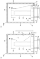
- FIGS. 2 (a) and 2 (b) are schematic views showing the cable insertion hole and its periphery.
- FIG. 2A shows the cable insertion hole 58 of the cryogenic refrigerator 100 according to the present embodiment and its periphery
- FIG. 2B shows the cable insertion hole 58a of the cryogenic refrigerator 100a according to the comparative example and its periphery. Indicates the surrounding area.
- FIG. 2B a part of the first stage 32 and the first radiation shield 62 is shown in cross section.
- the output cable 50 is not shown.
- the cable insertion hole 58 a is formed in the first radiation shield 62.
- the inventors have radiated heat that enters the radiation shield from the cable insertion hole, particularly, enters the radiation shield from the cable insertion hole, the two-stage cylinder, the inner wall of the radiation shield, It was also recognized that the radiant heat that radiates directly onto the two-stage stage without being reflected on the peripheral surface of the cable insertion hole has a relatively large effect on the cooling performance (attainment temperature) of the cryogenic refrigerator.
- the cryogenic refrigerator 100a according to the comparative example as indicated by an arrow in FIG.
- the radiant heat entering from the outside of the second radiation shield 64 through the cable insertion hole 58a can be directly applied to the second stage 38.
- the cable insertion hole 58a has a position, a size, and a size at which the radiant heat entering from the outside of the second radiation shield 64 through the cable insertion hole 58a can be directly applied to the second stage 38. It is formed into a shape. Therefore, in the cryogenic refrigerator 100a according to the comparative example, the cooling performance can be reduced.
- the cable insertion hole 58 is formed in the cylindrical portion 52 of the second radiation shield 64.
- the cable insertion hole 58 extends in the radial direction and penetrates through the second radiation shield 64.
- the cable insertion hole 58 is formed in a position, size, and shape in which the radiant heat that enters the outside of the second radiation shield 64 through the cable insertion hole 58 cannot be directly applied to the second stage 38.
- the two-stage stage 38 is provided at a position that avoids direct radiation heat entering from the cable insertion hole 58.
- the radiant heat that tries to enter the radiation shield 16 from the cable insertion hole 58 is directly applied to the peripheral surface of the two-stage cylinder 40 or the cable insertion hole 58.
- the radiant heat does not enter the two-stage stage 38 without being reflected by the peripheral surfaces of the two-stage cylinder 40 and the cable insertion hole 58, that is, does not directly enter the two-stage stage 38.
- the coupling mechanism 30 opens the high pressure valve.
- a high-pressure working gas is supplied from the compressor 10 through the pipe 12 to the expander 14.
- the coupling mechanism 30 closes the high-pressure valve 20 and opens the low-pressure valve 22.
- the working gas undergoes adiabatic expansion and is discharged to the compressor 10 through the pipe 12.
- the displacer member 46 reciprocates in the cylinder member 44 in synchronization with the supply and discharge of the working gas. By repeating such a heat cycle, the first stage 32 and the second stage 38 are cooled.
- the radiant heat entering the second radiation shield 64 through the cable insertion hole 58 can be directly applied to the peripheral surfaces of the two-stage cylinder 40 and the cable insertion hole 58 but cannot be directly applied to the two-stage stage 38.
- the cooling performance of the cryogenic refrigerator 100 is higher than that in the case where the radiant heat directly hits the two-stage stage 38.
- the radiant heat entering from the outside of the second radiation shield 64 through the cable insertion hole 58 is prevented from being directly applied to the second stage 38. Thereby, the cooling performance of the cryogenic refrigerator 100 is improved.
- cryogenic refrigerator has been described above.
- This embodiment is an exemplification, and it will be understood by those skilled in the art that various modifications can be made to combinations of the respective constituent elements and processing processes, and such modifications are also within the scope of the present invention. is there. A modification is shown below.
- Modification 1 In the embodiment, the case where the cable insertion hole 58 is formed in the second radiation shield 64 has been described. However, the present invention is not limited to this.
- the cable insertion hole 58 may be formed in the first radiation shield 62.
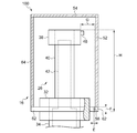
- FIG. 3 is a schematic diagram showing a cable insertion hole and its periphery of the cryogenic refrigerator 100 according to the modification.
- FIG. 3 corresponds to FIG.
- the cable insertion hole 58 is formed in the first radiation shield 62.
- the cable insertion hole 58 extends in the axial direction and penetrates the first radiation shield 62. Specifically, the cable insertion hole 58 is formed so as to satisfy the following expression at all positions of the two-stage stage 38.
- E is the width in the radial direction of the cable insertion hole 58
- F is the thickness in the axial direction of the first radiation shield 62
- G is the distance in the radial direction between the outer edge of the cable insertion hole 58 and the outer edge of the two-stage stage 38
- H is the distance from the lower end of the first radiation shield 62 to the upper end of the second stage 38.
- the radiant heat entering the second radiation shield 64 from the cable insertion hole 58 directly hits the inner wall of the second radiation shield 64 or the peripheral surface of the cable insertion hole 58. That is, the radiant heat does not directly hit the two-stage stage 38.
- FIG. 4 is a schematic diagram showing the cable insertion hole 58 and its periphery of a cryogenic refrigerator 100 according to another modification.
- FIG. 4 corresponds to FIG.
- a plurality of cable insertion holes 58 are shown, but any one of the cable insertion holes 58 may be formed.
- the cable insertion hole 58 is formed so as to extend in a direction intersecting the axial direction and the radial direction, thereby avoiding direct radiant heat to the two-stage stage 38.
- the cable insertion hole 58 may extend away from the second stage 38 as it goes from the outside to the inside of the radiation shield 16.
- Modification 3 In the embodiment and the above-described modification, the position, size, and shape of the cable insertion hole 58 are devised to suppress the direct radiation heat to the second stage 38.
- the present invention is not limited to this, and the second stage 38 is not limited thereto. It is also possible to suppress the radiation heat from directly hitting the two-stage stage 38 by shielding the path of the radiant heat toward the center with a shielding member.
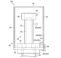
- FIG. 5 is a schematic diagram showing the cable insertion hole 58 and its periphery of a cryogenic refrigerator 100 according to still another modification.
- FIG. 5 corresponds to FIG.
- the cryogenic refrigerator 100 further includes a shielding member 60.
- a plurality of shielding members 60 are displayed, but at least one shielding member 60 may be provided.
- the cable insertion hole 58 is formed in the second radiation shield 64, but the cable insertion hole 58 may be formed in the first radiation shield 62.
- the shielding member 60 is formed of a material having high thermal conductivity such as aluminum or copper.
- the shielding member 60 a is a protruding portion that protrudes from the inner wall of the second radiation shield 64 toward the two-stage cylinder 40.
- the shielding member 60 a may be formed integrally with the second radiation shield 64, or may be formed separately from the second radiation shield 64 and supported by the second radiation shield 64.
- the shielding member 60 b is a protruding portion that protrudes from the outer peripheral surface of the first stage 32 toward the inner wall of the second radiation shield 64.
- the shielding member 60b may be formed integrally with the first stage 32, or may be formed separately from the first stage 32 and supported by the first stage 32.
- the shielding member 60 c is a protruding portion that protrudes from the outer peripheral surface of the two-stage cylinder 40 toward the inner wall of the second radiation shield 64.
- the shielding member 60 c may be formed integrally with the two-stage cylinder 40, or may be formed separately from the two-stage cylinder 40 and supported by the two-stage cylinder 40.
- the shielding member 60a, the shielding member 60b, and the shielding member 60c are all provided between the cable insertion hole 58 and the second stage 38.
- the shielding member 60a, the shielding member 60b, and the shielding member 60c particularly protrude so as to block the path of radiant heat toward the two-stage stage 38. Thereby, it is suppressed that radiant heat directly shines on the two-stage stage 38.
- the shielding member 60a, the shielding member 60b, and the shielding member 60c reflect the radiant heat toward the outside of the first stage 32 and the radiation shield 16, and thus the surface to which the radiant heat is directly irradiated (that is, the side opposite to the two-stage stage 38).
- the surface may be formed of a glossy surface.
- the glossy surface may be plated, for example.
- the shielding member 60d is partly connected to the cable insertion hole 58 after the output cable 50 is pulled out so that the radiant heat to be directly applied to the second stage 38 does not enter the second radiation shield 64 through the cable insertion hole 58. It is a cover member provided outside the second radiation shield 64 so as to face each other.
- the shielding member 60d is fixed to the first radiation shield 62.
- the shielding member 60d may be detachably fixed so that it can be removed during maintenance.
- the shielding member 60d may be, for example, an aluminum tape or a tape whose surface is gloss-plated.
- the cryogenic refrigerator 100 is a two-stage type has been described.
- the invention is not limited to this, and the number of stages of the cryogenic refrigerator 100 may be three or more.
- the first cylinder, the first cooling stage, the second cylinder, and the second cooling stage described in the claims are respectively a two-stage cylinder and a two-stage cooling. It may be realized by a stage, a three-stage cylinder, or a three-stage cooling stage.
- the present invention can be used for a cryogenic refrigerator that generates cold by expanding high-pressure refrigerant gas.
Landscapes
- Engineering & Computer Science (AREA)
- Physics & Mathematics (AREA)
- Mechanical Engineering (AREA)
- Thermal Sciences (AREA)
- General Engineering & Computer Science (AREA)
- Containers, Films, And Cooling For Superconductive Devices (AREA)
- Compressors, Vaccum Pumps And Other Relevant Systems (AREA)
- Devices That Are Associated With Refrigeration Equipment (AREA)
Abstract
極低温冷凍機(100)は、一段シリンダ(34)および二段シリンダ(40)と、一段シリンダ(34)の二段シリンダ(40)側の端部に設けられる一段ステージ(32)と、二段シリンダ(40)の一段シリンダ(34)とは反対側の端部に設けられる二段ステージ(38)と、二段ステージ(38)を収容し、二段ステージ(38)への外部からの輻射熱をシールドするための輻射シールド(16)と、二段ステージ(38)に取り付けられ、二段ステージ(38)の温度を検出する温度センサ(48)と、を備える。輻射シールド(16)には、輻射シールド(16)の中から外に温度センサ(48)の出力ケーブルを引き出すためのケーブル挿通孔(58)が形成されており、ケーブル挿通孔(58)は、輻射シールド(16)の外から中に入り込む輻射熱が二段ステージ(38)に直射しないように構成されている。
Description
本発明は、高圧の冷媒ガスを膨張させて寒冷を発生する極低温冷凍機に関する。
極低温を発生する冷凍機の一例としてギフォードマクマホン(Gifford-McMahon;GM)冷凍機が知られている。GM冷凍機は、シリンダ内でディスプレーサを往復移動することにより、膨張空間の体積を変化させる。この体積変化に対応して膨張空間と圧縮機の吐出側と吸気側とを選択的に接続することで、冷媒ガスが膨張空間で膨張する。
例えば特許文献1には、複数段の冷却部を備える多段式の極低温冷凍機が提案されている。多段式の極低温冷凍機は、一般に、二段目以降の冷凍能力が小さく、周囲からの輻射熱の影響を受けやすいため、輻射熱を遮蔽するための輻射シールドを備える。
本発明者らは、鋭意研究を重ねた結果、多段式の極低温冷凍機の冷却性能の向上を目指す上で、輻射熱のシールドに関して改善の余地があると認識するに至った。
本発明は、こうした状況に鑑みてなされたものであり、その目的は、多段式の極低温冷凍機の冷却性能を向上することにある。
上記課題を解決するために、本発明のある態様の極低温冷凍機は、直列に連結された第1シリンダおよび第2シリンダと、第1シリンダの第2シリンダ側の端部に設けられる第1冷却ステージと、第2シリンダの第1シリンダとは反対側の端部に設けられる第2冷却ステージと、を備える。第1シリンダおよび第2シリンダの内部に作動ガスを供給して膨張させて外部に排気することにより第1冷却ステージを第1の冷却温度に冷却するとともに第2冷却ステージを第1の冷却温度よりも低温である第2の冷却温度に冷却する極低温冷凍機であって、第2冷却ステージを収容し、第2ステージへの外部からの輻射熱をシールドするための輻射シールドと、第2冷却ステージに取り付けられ、第2冷却ステージの温度を検出する温度センサと、を備える。輻射シールドには、当該輻射シールドの中から外に温度センサの出力ケーブルを引き出すための挿通孔が形成されており、挿通孔は、輻射シールドの外から中に入り込む輻射熱が第2冷却ステージに直射しないように構成されている。
本発明の別の態様もまた、極低温冷凍機である。この極低温冷凍機は、直列に連結された第1シリンダおよび第2シリンダと、第1シリンダの第2シリンダ側の端部に設けられる第1冷却ステージと、第2シリンダの第1シリンダとは反対側の端部に設けられる第2冷却ステージと、を備える。第1シリンダおよび第2シリンダの内部に作動ガスを供給して膨張させて外部に排気することにより第1冷却ステージを第1の冷却温度に冷却するとともに第2冷却ステージを第1の冷却温度よりも低温である第2の冷却温度に冷却する極低温冷凍機であって、第2冷却ステージを収容し、第2ステージへの外部からの輻射熱をシールドするための輻射シールドと、第2冷却ステージに取り付けられ、第2冷却ステージの温度を検出する温度センサと、を備える。輻射シールドには、当該輻射シールドの中から外に温度センサの出力ケーブルを引き出すための挿通孔が形成されており、当該極低温冷凍機はさらに、挿通孔を通じて第2冷却ステージに直射しようとする輻射熱を遮蔽する遮蔽部材を備える。
なお、以上の構成要素の任意の組み合わせや、本発明の構成要素や表現を方法、装置、システムなどの間で相互に置換したものもまた、本発明の態様として有効である。
本発明によれば、多段式の極低温冷凍機の冷却性能を向上できる。
以下、各図面に示される同一または同等の構成要素、部材、工程には、同一の符号を付するものとし、適宜重複した説明は省略する。また、各図面における部材の寸法は、理解を容易にするために適宜拡大、縮小して示される。また、各図面において実施の形態を説明する上で重要ではない部材の一部は省略して表示する。
図1は、実施の形態に係る極低温冷凍機100を示す模式図である。図1では、第1輻射シールド62は断面で示されている。極低温冷凍機100は、ギフォード・マクマホン冷凍機(GM冷凍機)である。極低温冷凍機100は、二段式の極低温冷凍機であり、後述のように冷却部を直列に二段組み合わせてより低い温度を達成する。極低温冷凍機100は、圧縮機10と、配管12と、膨張機14と、輻射シールド16と、制御装置18と、を備える。
圧縮機10は、膨張機14から戻ってくる低圧の冷媒ガスを圧縮し、圧縮された高圧の冷媒ガスを膨張機14に供給する。配管12は、圧縮機10と膨張機14とを接続する。配管12には高圧バルブ20および低圧バルブ22が並列に設けられている。高圧の作動ガスは、圧縮機10から高圧バルブ20および配管12を介して圧縮機10に供給される。低圧の作動ガスは、配管12および低圧バルブ22を介して圧縮機10に排気される。冷媒ガスとしては、例えばヘリウムガスを用いることができる。なお、冷媒ガスとして窒素ガスやその他のガスを用いてもよい。
膨張機14は、圧縮機10から供給された高圧の冷媒ガスを膨張させて寒冷を発生させる。膨張機14は、一段冷却部24と、二段冷却部26と、駆動モータ28と、連結機構30と、温度センサ48と、を備える。一段冷却部24は、一段ステージ32と、一段シリンダ34と、一段ディスプレーサ36と、を備える。二段冷却部26は、二段ステージ38と、二段シリンダ40と、二段ディスプレーサ42と、を備える。一段冷却部24と二段冷却部26とは、直列に接続されている。
以降、一段シリンダ34および二段シリンダ40が延在する方向を軸方向とし、軸方向において一段シリンダ34に対して二段シリンダ40が設けられる側を上側として説明する。なお、軸方向は、一段ディスプレーサ36および二段ディスプレーサ42が移動する方向とも一致する。また、軸方向に直交する方向を径方向とし、径方向において一段ディスプレーサ36および二段ディスプレーサ42から遠い側を外側近い側を内側として説明する。なお、これらの表記は、極低温冷凍機100が使用される姿勢を制限するものではなく、極低温冷凍機100は任意の姿勢で使用され得る。
一段シリンダ34と二段シリンダ40は、同軸に直列に接続され、1つのシリンダ部材44を形成する。同様に、一段ディスプレーサ36と二段ディスプレーサ42は、同軸に直列に接続され、1つのディスプレーサ部材46を形成する。シリンダ部材44は、ディスプレーサ部材46を収容する中空の気密容器であり、軸方向にディスプレーサ部材46の往復移動を案内する。
一段ステージ32は、環状の部材であり、一段シリンダ34の上端を環囲するように一段シリンダ34に固定される。二段ステージ38は、二段シリンダ40の上端を環囲するように二段シリンダ40の上端に固定される。二段ステージ38は、一段ステージ32よりも低温に冷却される。二段ステージ38は、例えば2K~10K程度に冷却され、一段ステージ32は、例えば30K~80K程度に冷却される。一段ステージ32と二段ステージ38は、アルミニウムや銅などの熱伝導率の高い材料により形成される。
温度センサ48は、二段ステージ38の温度を測定するための温度センサであり、二段ステージ38に取り付けられている。温度センサ48は所定の周期で二段ステージ38の温度を検出し、検出値は出力ケーブル50を介して出力される。図1の例では、温度センサ48は出力ケーブル50により制御装置18と接続され、検出値は制御装置18に出力される。
駆動モータ28は、連結機構30を介してディスプレーサ部材46に連結されている。連結機構30は、例えばスコッチヨーク機構を含む。駆動モータ28および連結機構30により、ディスプレーサ部材46は軸方向に一体に往復運動する。また、連結機構30は、この往復運動に連動して高圧バルブ20の開弁と低圧バルブ22の開弁とを選択的に切り替えるように高圧バルブ20および低圧バルブ22に連結されている。つまり、ディスプレーサ部材46の往復運動に連動して作動ガスの給気と排気とが切り替えられるように構成されている。
制御装置18は、圧縮機10および駆動モータ28を制御する。制御装置18は例えば、圧縮機10の高圧と低圧との圧力差を目標圧に制御する。
輻射シールド16は、二段シリンダ40および二段ステージ38を収容し、周囲からの輻射熱が二段ステージ38に侵入するのを抑制する。輻射シールド16は、例えばアルミニウムや銅などの熱伝導率の高い材料により形成される。また輻射熱を反射するために、輻射シールド16の外表面に光沢メッキ加工を施してもよい。輻射シールド16は、第1輻射シールド62と、第2輻射シールド64と、を含む。
第1輻射シールド62は、円板状の部材であり、一段ステージ32を環囲する。第1輻射シールド62は、一段ステージ32と一体に形成されても、一段ステージ32とは別体として形成された上で一段ステージ32に結合されてもよい。例えば、第1輻射シールド62は、一段ステージ32と一体に形成される一段ステージ32を冷却対象物に接続するためのフランジであってもよい。第2輻射シールド64は、円筒部52と底部54とが一体に形成された有底カップ形状を有する。第2輻射シールド64は、底部54を上にして、開口が第1輻射シールド62によって塞がれるように第1輻射シールド62に固定される。第1輻射シールド62および第2輻射シールド64は、一段ステージ32と熱的に接続されているため、一段ステージ32により冷却される。第2輻射シールド64には、温度センサ48の出力ケーブル50を第2輻射シールド64の外に引き出すためのケーブル挿通孔58が形成されている。
図2(a)、(b)は、ケーブル挿通孔とその周辺を示す模式図である。図2(a)は本実施の形態に係る極低温冷凍機100のケーブル挿通孔58とその周辺を示し、図2(b)は比較例に係る極低温冷凍機100aのケーブル挿通孔58aとその周辺を示す。図2(b)では、一段ステージ32および第1輻射シールド62の一部を断面で示している。図2(a)、(b)では、出力ケーブル50の表示は省略している。
図2(b)に示す比較例に係る極低温冷凍機100aでは、ケーブル挿通孔58aは第1輻射シールド62に形成されている。ここで、本発明者らは、鋭意研究を重ねた結果、ケーブル挿通孔から輻射シールドの中に入り込む輻射熱が、特にケーブル挿通孔から輻射シールドの中に入り込み、二段シリンダ、輻射シールドの内壁、およびケーブル挿通孔の周面に反射することなく二段ステージに直射する輻射熱が、極低温冷凍機の冷却性能(到達温度)に比較的大きな影響を与えていることを認識した。比較例に係る極低温冷凍機100aでは、図2(b)中に矢印で示すように、ケーブル挿通孔58aを通じて第2輻射シールド64の外から中に入り込む輻射熱が二段ステージ38に直射しうる。つまり、比較例に係る極低温冷凍機100aでは、ケーブル挿通孔58aは、ケーブル挿通孔58aを通じて第2輻射シールド64の外から中に入り込む輻射熱が二段ステージ38に直射可能な位置、大きさ、形状に形成されている。そのため、比較例に係る極低温冷凍機100aでは、冷却性能の低下を招きうる。
図2(a)に示す本実施の形態に係る極低温冷凍機100では、ケーブル挿通孔58は、第2輻射シールド64の円筒部52に形成されている。ケーブル挿通孔58は、径方向に延在して第2輻射シールド64を貫通している。ケーブル挿通孔58は特に、ケーブル挿通孔58を通じて第2輻射シールド64の外から中に入り込む輻射熱が二段ステージ38に直射不可能な位置、大きさ、形状に形成される。別の言い方をすると、二段ステージ38が、ケーブル挿通孔58から入り込む輻射熱の直射を避けた位置に設けられている。
具体的には、ケーブル挿通孔58は、二段ステージ38よりも下方すなわち二段ステージ38よりも二段シリンダ40側に設けられる場合、二段ステージ38のすべての位置において次式を満たすように形成される。
(式1)A/B<C/D
ここで、Aは円筒部52の外周面と二段ステージ38の内周面(すなわち二段シリンダ40の外周面)との径方向における距離、Bはケーブル挿通孔58の下端から二段ステージ38の下端までの軸方向における距離、Cは第2輻射シールド64の径方向における厚み、Dはケーブル挿通孔58の軸方向の幅である。
(式1)A/B<C/D
ここで、Aは円筒部52の外周面と二段ステージ38の内周面(すなわち二段シリンダ40の外周面)との径方向における距離、Bはケーブル挿通孔58の下端から二段ステージ38の下端までの軸方向における距離、Cは第2輻射シールド64の径方向における厚み、Dはケーブル挿通孔58の軸方向の幅である。
この場合、ケーブル挿通孔58から輻射シールド16内に入り込もうとする輻射熱は、二段シリンダ40またはケーブル挿通孔58の周面に直射する。すなわち、輻射熱が、二段シリンダ40やケーブル挿通孔58の周面に反射することなく二段ステージ38に入射するすなわち二段ステージ38に直射することはない。
以上のように構成された極低温冷凍機100の動作を説明する。
連結機構30は高圧バルブを開く。圧縮機10から配管12を通じて膨張機14に高圧の作動ガスが供給される。膨張機14の内部空間が高圧の作動ガスで満たされると、連結機構30は高圧バルブ20を閉じるとともに低圧バルブ22を開く。作動ガスは断熱膨張し、配管12を通じて圧縮機10へと排出される。こうした作動ガスの給排に同期して、ディスプレーサ部材46がシリンダ部材44の内部を往復動する。このような熱サイクルを繰り返すことで一段ステージ32および二段ステージ38が冷却される。
連結機構30は高圧バルブを開く。圧縮機10から配管12を通じて膨張機14に高圧の作動ガスが供給される。膨張機14の内部空間が高圧の作動ガスで満たされると、連結機構30は高圧バルブ20を閉じるとともに低圧バルブ22を開く。作動ガスは断熱膨張し、配管12を通じて圧縮機10へと排出される。こうした作動ガスの給排に同期して、ディスプレーサ部材46がシリンダ部材44の内部を往復動する。このような熱サイクルを繰り返すことで一段ステージ32および二段ステージ38が冷却される。
この際、ケーブル挿通孔58を通じて第2輻射シールド64内に入り込む輻射熱は、二段シリンダ40やケーブル挿通孔58の周面には直射しうるものの、二段ステージ38には直射できない。これにより、極低温冷凍機100の冷却性能は、輻射熱が二段ステージ38に直射する場合に比べて高くなる。
以上説明した本実施の形態に係る極低温冷凍機100によると、ケーブル挿通孔58を通じて第2輻射シールド64の外から中に入り込む輻射熱が二段ステージ38に直射するのが抑止される。これにより、極低温冷凍機100の冷却性能が向上する。
以上、実施の形態に係る極低温冷凍機について説明した。この実施の形態は例示であり、それらの各構成要素や各処理プロセスの組合せにいろいろな変形例が可能なこと、またそうした変形例も本発明の範囲にあることは当業者に理解されるところである。以下変形例を示す。
(変形例1)
実施の形態では、ケーブル挿通孔58が第2輻射シールド64に形成される場合について説明したが、これに限られない。ケーブル挿通孔58は、第1輻射シールド62に形成されてもよい。
実施の形態では、ケーブル挿通孔58が第2輻射シールド64に形成される場合について説明したが、これに限られない。ケーブル挿通孔58は、第1輻射シールド62に形成されてもよい。
図3は、変形例にかかる極低温冷凍機100のケーブル挿通孔とその周辺を示す模式図である。図3は、図2(a)に対応する。本変形例では、ケーブル挿通孔58は、第1輻射シールド62に形成されている。
ケーブル挿通孔58は、軸方向に延在して第1輻射シールド62を貫通している。具体的には、ケーブル挿通孔58は、二段ステージ38のすべての位置において次式を満たすように形成される。
(式2)E/F<G/H
ここで、Eはケーブル挿通孔58の径方向の幅、Fは第1輻射シールド62の軸方向における厚み、Gはケーブル挿通孔58の外縁と二段ステージ38の外縁との径方向における距離、Hは第1輻射シールド62の下端から二段ステージ38の上端までの距離である。
(式2)E/F<G/H
ここで、Eはケーブル挿通孔58の径方向の幅、Fは第1輻射シールド62の軸方向における厚み、Gはケーブル挿通孔58の外縁と二段ステージ38の外縁との径方向における距離、Hは第1輻射シールド62の下端から二段ステージ38の上端までの距離である。
この場合、ケーブル挿通孔58から第2輻射シールド64内に入り込もうとする輻射熱は、第2輻射シールド64の内壁またはケーブル挿通孔58の周面に直射する。すなわち、輻射熱が二段ステージ38に直射することはない。
(変形例2)
図4は、別の変形例に係る極低温冷凍機100のケーブル挿通孔58とその周辺を示す模式図である。図4は、図2(a)に対応する。なお、図4では、複数のケーブル挿通孔58を表示しているが、いずれか1つのケーブル挿通孔58が形成されればよい。本変形例では、軸方向および径方向に交差する方向に延在するようケーブル挿通孔58を形成することにより、輻射熱が二段ステージ38に直射するのを避けている。ケーブル挿通孔58は、例えば、輻射シールド16の外から中に向かうにつれて、二段ステージ38から離れるように延在していてもよい。
図4は、別の変形例に係る極低温冷凍機100のケーブル挿通孔58とその周辺を示す模式図である。図4は、図2(a)に対応する。なお、図4では、複数のケーブル挿通孔58を表示しているが、いずれか1つのケーブル挿通孔58が形成されればよい。本変形例では、軸方向および径方向に交差する方向に延在するようケーブル挿通孔58を形成することにより、輻射熱が二段ステージ38に直射するのを避けている。ケーブル挿通孔58は、例えば、輻射シールド16の外から中に向かうにつれて、二段ステージ38から離れるように延在していてもよい。
(変形例3)
実施の形態および上述の変形例では、ケーブル挿通孔58の位置、大きさ、形状を工夫することによって輻射熱が二段ステージ38に直射するのを抑制したが、これに限られず、二段ステージ38に向かう輻射熱の経路を遮蔽部材により遮蔽することによって輻射熱が二段ステージ38に直射するのを抑制してもよい。
実施の形態および上述の変形例では、ケーブル挿通孔58の位置、大きさ、形状を工夫することによって輻射熱が二段ステージ38に直射するのを抑制したが、これに限られず、二段ステージ38に向かう輻射熱の経路を遮蔽部材により遮蔽することによって輻射熱が二段ステージ38に直射するのを抑制してもよい。
図5は、さらに別の変形例に係る極低温冷凍機100のケーブル挿通孔58とその周辺を示す模式図である。図5は、図2(a)に対応する。本変形例では、極低温冷凍機100は、遮蔽部材60をさらに備える。なお、図4では、複数の遮蔽部材60を表示しているが、少なくとも1つの遮蔽部材60が設けられればよい。また、図4では、ケーブル挿通孔58が第2輻射シールド64に形成されているが、ケーブル挿通孔58は第1輻射シールド62に形成されてもよい。
遮蔽部材60は、例えば、アルミニウムや銅などの熱伝導率の高い材料により形成される。
遮蔽部材60aは、第2輻射シールド64の内壁から二段シリンダ40に向けて突出する突出部である。遮蔽部材60aは、第2輻射シールド64と一体に形成されても、第2輻射シールド64とは別体として形成された上で第2輻射シールド64に支持されてもよい。
遮蔽部材60bは、一段ステージ32の外周面から第2輻射シールド64の内壁に向けて突出する突出部である。遮蔽部材60bは、一段ステージ32と一体に形成されても、一段ステージ32とは別体として形成された上で一段ステージ32に支持されてもよい。
遮蔽部材60cは、二段シリンダ40の外周面から第2輻射シールド64の内壁に向けて突出する突出部である。遮蔽部材60cは、二段シリンダ40と一体に形成されても、二段シリンダ40とは別体として形成された上で二段シリンダ40に支持されてもよい。
つまり、遮蔽部材60a、遮蔽部材60b、遮蔽部材60cはいずれも、ケーブル挿通孔58と二段ステージ38との間に設けられる。遮蔽部材60a、遮蔽部材60b、遮蔽部材60cは特に、二段ステージ38に向かう輻射熱の経路を遮るように突出する。これにより、輻射熱が二段ステージ38に直射するのが抑制される。
なお、遮蔽部材60a、遮蔽部材60b、遮蔽部材60cは、輻射熱を一段ステージ32や輻射シールド16外に向けて反射するために、輻射熱が直射される表面(すなわち二段ステージ38とは反対側の表面)が光沢面で形成されてもよい。その光沢面には、たとえばメッキ加工が施されていてもよい。
遮蔽部材60dは、二段ステージ38に直射するべき輻射熱がケーブル挿通孔58を通じて第2輻射シールド64の中に入り込まないように、出力ケーブル50を引き出した後に、その一部がケーブル挿通孔58と対向するように第2輻射シールド64の外側に設けられるカバー部材である。遮蔽部材60dは、第1輻射シールド62に固定されている。遮蔽部材60dは、メンテナンス時に取り外せるように、取り外し可能に固定されてもよい。遮蔽部材60dは、例えばアルミニウム製のテープや表面に光沢メッキが施されたテープでもよい。
本変形例によれば、挿通孔から輻射シールド16の中に入り込もうとする輻射熱が二段ステージ38に直射する位置にケーブル挿通孔58が形成される場合でも、上述の実施の形態と同様の効果を奏することができる。そのため、ケーブル挿通孔58を形成する位置および大きさの自由度が増す。
(変形例4)
実施の形態では、極低温冷凍機100が二段式である場合について説明したが、これに限られず、極低温冷凍機100の段数は三段以上であってもよい。例えば極低温冷凍機100が三段式の極低温冷凍機の場合、請求項に記載の第1シリンダ、第1冷却ステージ、第2シリンダ、第2冷却ステージはそれぞれ、二段シリンダ、二段冷却ステージ、三段シリンダ、三段冷却ステージにより実現されてもよい。
実施の形態では、極低温冷凍機100が二段式である場合について説明したが、これに限られず、極低温冷凍機100の段数は三段以上であってもよい。例えば極低温冷凍機100が三段式の極低温冷凍機の場合、請求項に記載の第1シリンダ、第1冷却ステージ、第2シリンダ、第2冷却ステージはそれぞれ、二段シリンダ、二段冷却ステージ、三段シリンダ、三段冷却ステージにより実現されてもよい。
上述した前提技術と実施の形態と変形例の任意の組み合わせもまた本発明の実施の形態として有用である。組み合わせによって生じる新たな実施の形態は、組み合わされる実施の形態および変形例それぞれの効果をあわせもつ。
16 輻射シールド、 32 一段ステージ、 34 一段シリンダ、 38 二段ステージ、 40 二段シリンダ、 48 温度センサ、 50 出力ケーブル、 58,60 遮蔽部材、 62 第1輻射シールド、 64 第2輻射シールド、 100 極低温冷凍機。
本発明は、高圧の冷媒ガスを膨張させて寒冷を発生する極低温冷凍機に利用できる。
Claims (6)
- 直列に連結された第1シリンダおよび第2シリンダと、
前記第1シリンダの前記第2シリンダ側の端部に設けられる第1冷却ステージと、
前記第2シリンダの前記第1シリンダとは反対側の端部に設けられる第2冷却ステージと、を備え、
前記第1シリンダおよび前記第2シリンダの内部に作動ガスを供給して膨張させて外部に排気することにより前記第1冷却ステージを第1の冷却温度に冷却するとともに前記第2冷却ステージを第1の冷却温度よりも低温である第2の冷却温度に冷却する極低温冷凍機であって、
前記第1冷却ステージに冷却され、前記第2冷却ステージを収容し、前記第2冷却ステージへの外部からの輻射熱をシールドするための輻射シールドと、
前記第2冷却ステージに取り付けられ、前記第2冷却ステージの温度を検出する温度センサと、を備え、
前記輻射シールドには、当該輻射シールドの中から外に前記温度センサの出力ケーブルを引き出すための挿通孔が形成されており、
前記挿通孔は、前記輻射シールドの外から中に入り込む輻射熱が前記第2冷却ステージに直射しないように構成されていることを特徴とする極低温冷凍機。 - 前記挿通孔は、前記輻射シールドの中に入り込む輻射熱が前記第2シリンダ、前記挿通孔の周面、または前記輻射シールドの内壁に直射するよう形成されていることを特徴とする請求項1に記載の極低温冷凍機。
- 前記挿通孔は、当該挿通孔から前記輻射シールドの中に入り込もうとする輻射熱が前記第2冷却ステージに直射する位置に形成されており、当該輻射熱を遮蔽する遮蔽部材を備えることを特徴とする請求項1に記載の極低温冷凍機。
- 前記遮蔽部材は、前記挿通孔と前記第2冷却ステージとの間に配置され、前記輻射シールドまたは前記第1冷却ステージに支持されていることを特徴とする請求項3に記載の極低温冷凍機。
- 前記遮蔽部材は、前記出力ケーブルを引き出した後に前記挿通孔を閉塞するカバー部材であることを特徴とする請求項3に記載の極低温冷凍機。
- 前記遮蔽部材は、前記輻射熱が直射する表面を金属で形成されることを特徴とする請求項3から5のいずれかに記載の極低温冷凍機。
Priority Applications (2)
| Application Number | Priority Date | Filing Date | Title |
|---|---|---|---|
| CN201880013396.XA CN110382975B (zh) | 2017-03-15 | 2018-03-02 | 超低温制冷机 |
| US16/570,011 US11566821B2 (en) | 2017-03-15 | 2019-09-13 | Cryocooler |
Applications Claiming Priority (2)
| Application Number | Priority Date | Filing Date | Title |
|---|---|---|---|
| JP2017-049497 | 2017-03-15 | ||
| JP2017049497A JP6773589B2 (ja) | 2017-03-15 | 2017-03-15 | 極低温冷凍機 |
Related Child Applications (1)
| Application Number | Title | Priority Date | Filing Date |
|---|---|---|---|
| US16/570,011 Continuation US11566821B2 (en) | 2017-03-15 | 2019-09-13 | Cryocooler |
Publications (1)
| Publication Number | Publication Date |
|---|---|
| WO2018168535A1 true WO2018168535A1 (ja) | 2018-09-20 |
Family
ID=63523012
Family Applications (1)
| Application Number | Title | Priority Date | Filing Date |
|---|---|---|---|
| PCT/JP2018/008135 Ceased WO2018168535A1 (ja) | 2017-03-15 | 2018-03-02 | 極低温冷凍機 |
Country Status (4)
| Country | Link |
|---|---|
| US (1) | US11566821B2 (ja) |
| JP (1) | JP6773589B2 (ja) |
| CN (1) | CN110382975B (ja) |
| WO (1) | WO2018168535A1 (ja) |
Families Citing this family (3)
| Publication number | Priority date | Publication date | Assignee | Title |
|---|---|---|---|---|
| JP7319462B2 (ja) * | 2020-04-23 | 2023-08-01 | 住友重機械工業株式会社 | 超電導磁石装置、および超電導磁石装置の冷却方法 |
| JP2023076871A (ja) | 2021-11-24 | 2023-06-05 | 浜松ホトニクス株式会社 | 冷凍システム |
| US20240292568A1 (en) * | 2023-02-27 | 2024-08-29 | The United States Of America As Represented By The Secretary Of The Navy | Cryogenic Platform |
Citations (6)
| Publication number | Priority date | Publication date | Assignee | Title |
|---|---|---|---|---|
| JPS62140707U (ja) * | 1986-02-27 | 1987-09-05 | ||
| JPH06132567A (ja) * | 1992-10-20 | 1994-05-13 | Sumitomo Heavy Ind Ltd | 伝導冷却型超電導磁石装置 |
| JP2004027866A (ja) * | 2002-06-21 | 2004-01-29 | Aisin Seiki Co Ltd | クライオポンプ装置及びクライオポンプ装置の運転方法 |
| JP2004233047A (ja) * | 2004-02-09 | 2004-08-19 | Mitsubishi Electric Corp | 超電導マグネット |
| JP2009270736A (ja) * | 2008-04-30 | 2009-11-19 | Chubu Electric Power Co Inc | 極低温装置 |
| JP2013160393A (ja) * | 2012-02-01 | 2013-08-19 | Sumitomo Heavy Ind Ltd | 冷凍機装着構造 |
Family Cites Families (18)
| Publication number | Priority date | Publication date | Assignee | Title |
|---|---|---|---|---|
| US5623240A (en) | 1992-10-20 | 1997-04-22 | Sumitomo Heavy Industries, Ltd. | Compact superconducting magnet system free from liquid helium |
| JP4500265B2 (ja) * | 2003-11-20 | 2010-07-14 | 住友重機械工業株式会社 | クライオポンプ |
| JP4857896B2 (ja) * | 2006-05-11 | 2012-01-18 | トヨタ自動車株式会社 | 組電池および車両 |
| CN201141967Y (zh) * | 2007-10-31 | 2008-10-29 | 天津市亚安科技电子有限公司 | 云台摄像机外壳散热结构 |
| TWI490408B (zh) * | 2008-04-04 | 2015-07-01 | Brooks Automation Inc | 利用錫鎵合金的低溫泵 |
| JP5433378B2 (ja) * | 2009-10-29 | 2014-03-05 | 株式会社日立製作所 | 電池電源装置 |
| CN101766359A (zh) * | 2010-01-09 | 2010-07-07 | 徐博 | 一种带有遮阳通风罩的头冠 |
| JP5744692B2 (ja) * | 2011-10-05 | 2015-07-08 | 住友重機械工業株式会社 | 極低温冷凍機及びクライオポンプ及びディスプレーサ |
| KR101910356B1 (ko) * | 2012-04-04 | 2018-10-22 | 에스엘 주식회사 | 이너부재를 포함한 차량용 램프 |
| JP5972666B2 (ja) * | 2012-05-22 | 2016-08-17 | 住友重機械工業株式会社 | 冷却システム及びメンテナンス要否判定方法 |
| JP6161879B2 (ja) * | 2012-07-27 | 2017-07-12 | 住友重機械工業株式会社 | 極低温冷凍機 |
| JP6117090B2 (ja) * | 2013-12-18 | 2017-04-19 | 住友重機械工業株式会社 | 極低温冷凍機 |
| CN204012303U (zh) * | 2014-01-14 | 2014-12-10 | 万电电气股份有限公司 | 户外落地式配电箱 |
| JP6180349B2 (ja) * | 2014-03-18 | 2017-08-16 | 住友重機械工業株式会社 | 極低温冷凍機および極低温冷凍機の制御方法 |
| CN203847833U (zh) * | 2014-04-09 | 2014-09-24 | 安徽中德机床股份有限公司 | 一种防雨桥架 |
| CN204028170U (zh) * | 2014-06-27 | 2014-12-17 | 国家电网公司 | 一种智能电表和预付费插卡电表表箱 |
| JP6305287B2 (ja) | 2014-09-11 | 2018-04-04 | 住友重機械工業株式会社 | 極低温冷凍機 |
| JP2016075429A (ja) * | 2014-10-07 | 2016-05-12 | 住友重機械工業株式会社 | 極低温冷凍機 |
-
2017
- 2017-03-15 JP JP2017049497A patent/JP6773589B2/ja active Active
-
2018
- 2018-03-02 WO PCT/JP2018/008135 patent/WO2018168535A1/ja not_active Ceased
- 2018-03-02 CN CN201880013396.XA patent/CN110382975B/zh active Active
-
2019
- 2019-09-13 US US16/570,011 patent/US11566821B2/en active Active
Patent Citations (6)
| Publication number | Priority date | Publication date | Assignee | Title |
|---|---|---|---|---|
| JPS62140707U (ja) * | 1986-02-27 | 1987-09-05 | ||
| JPH06132567A (ja) * | 1992-10-20 | 1994-05-13 | Sumitomo Heavy Ind Ltd | 伝導冷却型超電導磁石装置 |
| JP2004027866A (ja) * | 2002-06-21 | 2004-01-29 | Aisin Seiki Co Ltd | クライオポンプ装置及びクライオポンプ装置の運転方法 |
| JP2004233047A (ja) * | 2004-02-09 | 2004-08-19 | Mitsubishi Electric Corp | 超電導マグネット |
| JP2009270736A (ja) * | 2008-04-30 | 2009-11-19 | Chubu Electric Power Co Inc | 極低温装置 |
| JP2013160393A (ja) * | 2012-02-01 | 2013-08-19 | Sumitomo Heavy Ind Ltd | 冷凍機装着構造 |
Also Published As
| Publication number | Publication date |
|---|---|
| JP6773589B2 (ja) | 2020-10-21 |
| CN110382975B (zh) | 2021-11-16 |
| JP2018151148A (ja) | 2018-09-27 |
| CN110382975A (zh) | 2019-10-25 |
| US11566821B2 (en) | 2023-01-31 |
| US20200003460A1 (en) | 2020-01-02 |
Similar Documents
| Publication | Publication Date | Title |
|---|---|---|
| JP5632241B2 (ja) | クライオポンプ及び極低温冷凍機 | |
| JP6214498B2 (ja) | 極低温冷凍機 | |
| US10465671B2 (en) | Compressor with a discharge muffler | |
| US9976779B2 (en) | Cryogenic refrigerator | |
| JP5660979B2 (ja) | クライオポンプ及び極低温冷凍機 | |
| US20160097567A1 (en) | Cryogenic refrigerator | |
| WO2018168535A1 (ja) | 極低温冷凍機 | |
| KR101674087B1 (ko) | 축냉식 냉동기 | |
| US9976780B2 (en) | Stirling-type pulse tube refrigerator | |
| US9146047B2 (en) | Integrated Stirling refrigerator | |
| CN108800713B (zh) | 采用斯特林制冷机的多温区风冷冰箱及控温方法 | |
| JP6117090B2 (ja) | 極低温冷凍機 | |
| CN108518912B (zh) | 采用脉管型自由活塞斯特林制冷机的多温区风冷冰箱 | |
| JP6376793B2 (ja) | 蓄冷器式冷凍機 | |
| KR101856281B1 (ko) | 왕복동식 압축기 | |
| JP6792990B2 (ja) | 極低温冷凍機 | |
| JP2019128082A (ja) | 蓄冷型冷凍機 | |
| CN102713468B (zh) | 超低温制冷机 | |
| JP6320142B2 (ja) | 極低温冷凍機 | |
| JP6911649B2 (ja) | 多段型蓄冷式冷凍機 | |
| JP2017048937A (ja) | 極低温冷凍機 | |
| JP2013174393A (ja) | 極低温冷凍機 | |
| JP2007205679A (ja) | 蓄冷器式冷凍機 | |
| JP6842373B2 (ja) | 極低温冷凍機 | |
| JP2024179005A (ja) | 極低温冷凍機 |
Legal Events
| Date | Code | Title | Description |
|---|---|---|---|
| 121 | Ep: the epo has been informed by wipo that ep was designated in this application |
Ref document number: 18767565 Country of ref document: EP Kind code of ref document: A1 |
|
| NENP | Non-entry into the national phase |
Ref country code: DE |
|
| 122 | Ep: pct application non-entry in european phase |
Ref document number: 18767565 Country of ref document: EP Kind code of ref document: A1 |