WO2018168445A1 - サービスプラグ - Google Patents
サービスプラグ Download PDFInfo
- Publication number
- WO2018168445A1 WO2018168445A1 PCT/JP2018/007273 JP2018007273W WO2018168445A1 WO 2018168445 A1 WO2018168445 A1 WO 2018168445A1 JP 2018007273 W JP2018007273 W JP 2018007273W WO 2018168445 A1 WO2018168445 A1 WO 2018168445A1
- Authority
- WO
- WIPO (PCT)
- Prior art keywords
- terminal
- service plug
- unit
- power
- power supply
- Prior art date
- Legal status (The legal status is an assumption and is not a legal conclusion. Google has not performed a legal analysis and makes no representation as to the accuracy of the status listed.)
- Ceased
Links
Images



Classifications
-
- B—PERFORMING OPERATIONS; TRANSPORTING
- B60—VEHICLES IN GENERAL
- B60L—PROPULSION OF ELECTRICALLY-PROPELLED VEHICLES; SUPPLYING ELECTRIC POWER FOR AUXILIARY EQUIPMENT OF ELECTRICALLY-PROPELLED VEHICLES; ELECTRODYNAMIC BRAKE SYSTEMS FOR VEHICLES IN GENERAL; MAGNETIC SUSPENSION OR LEVITATION FOR VEHICLES; MONITORING OPERATING VARIABLES OF ELECTRICALLY-PROPELLED VEHICLES; ELECTRIC SAFETY DEVICES FOR ELECTRICALLY-PROPELLED VEHICLES
- B60L50/00—Electric propulsion with power supplied within the vehicle
- B60L50/50—Electric propulsion with power supplied within the vehicle using propulsion power supplied by batteries or fuel cells
- B60L50/60—Electric propulsion with power supplied within the vehicle using propulsion power supplied by batteries or fuel cells using power supplied by batteries
- B60L50/64—Constructional details of batteries specially adapted for electric vehicles
-
- H—ELECTRICITY
- H01—ELECTRIC ELEMENTS
- H01R—ELECTRICALLY-CONDUCTIVE CONNECTIONS; STRUCTURAL ASSOCIATIONS OF A PLURALITY OF MUTUALLY-INSULATED ELECTRICAL CONNECTING ELEMENTS; COUPLING DEVICES; CURRENT COLLECTORS
- H01R13/00—Details of coupling devices of the kinds covered by groups H01R12/70 or H01R24/00 - H01R33/00
- H01R13/62—Means for facilitating engagement or disengagement of coupling parts or for holding them in engagement
- H01R13/629—Additional means for facilitating engagement or disengagement of coupling parts, e.g. aligning or guiding means, levers, gas pressure electrical locking indicators, manufacturing tolerances
- H01R13/633—Additional means for facilitating engagement or disengagement of coupling parts, e.g. aligning or guiding means, levers, gas pressure electrical locking indicators, manufacturing tolerances for disengagement only
- H01R13/637—Additional means for facilitating engagement or disengagement of coupling parts, e.g. aligning or guiding means, levers, gas pressure electrical locking indicators, manufacturing tolerances for disengagement only by fluid pressure, e.g. explosion
-
- B—PERFORMING OPERATIONS; TRANSPORTING
- B60—VEHICLES IN GENERAL
- B60L—PROPULSION OF ELECTRICALLY-PROPELLED VEHICLES; SUPPLYING ELECTRIC POWER FOR AUXILIARY EQUIPMENT OF ELECTRICALLY-PROPELLED VEHICLES; ELECTRODYNAMIC BRAKE SYSTEMS FOR VEHICLES IN GENERAL; MAGNETIC SUSPENSION OR LEVITATION FOR VEHICLES; MONITORING OPERATING VARIABLES OF ELECTRICALLY-PROPELLED VEHICLES; ELECTRIC SAFETY DEVICES FOR ELECTRICALLY-PROPELLED VEHICLES
- B60L3/00—Electric devices on electrically-propelled vehicles for safety purposes; Monitoring operating variables, e.g. speed, deceleration or energy consumption
- B60L3/0007—Measures or means for preventing or attenuating collisions
-
- B—PERFORMING OPERATIONS; TRANSPORTING
- B60—VEHICLES IN GENERAL
- B60L—PROPULSION OF ELECTRICALLY-PROPELLED VEHICLES; SUPPLYING ELECTRIC POWER FOR AUXILIARY EQUIPMENT OF ELECTRICALLY-PROPELLED VEHICLES; ELECTRODYNAMIC BRAKE SYSTEMS FOR VEHICLES IN GENERAL; MAGNETIC SUSPENSION OR LEVITATION FOR VEHICLES; MONITORING OPERATING VARIABLES OF ELECTRICALLY-PROPELLED VEHICLES; ELECTRIC SAFETY DEVICES FOR ELECTRICALLY-PROPELLED VEHICLES
- B60L3/00—Electric devices on electrically-propelled vehicles for safety purposes; Monitoring operating variables, e.g. speed, deceleration or energy consumption
- B60L3/04—Cutting off the power supply under fault conditions
-
- B—PERFORMING OPERATIONS; TRANSPORTING
- B60—VEHICLES IN GENERAL
- B60R—VEHICLES, VEHICLE FITTINGS, OR VEHICLE PARTS, NOT OTHERWISE PROVIDED FOR
- B60R16/00—Electric or fluid circuits specially adapted for vehicles and not otherwise provided for; Arrangement of elements of electric or fluid circuits specially adapted for vehicles and not otherwise provided for
- B60R16/02—Electric or fluid circuits specially adapted for vehicles and not otherwise provided for; Arrangement of elements of electric or fluid circuits specially adapted for vehicles and not otherwise provided for electric constitutive elements
- B60R16/03—Electric or fluid circuits specially adapted for vehicles and not otherwise provided for; Arrangement of elements of electric or fluid circuits specially adapted for vehicles and not otherwise provided for electric constitutive elements for supply of electrical power to vehicle subsystems or for
- B60R16/033—Electric or fluid circuits specially adapted for vehicles and not otherwise provided for; Arrangement of elements of electric or fluid circuits specially adapted for vehicles and not otherwise provided for electric constitutive elements for supply of electrical power to vehicle subsystems or for characterised by the use of electrical cells or batteries
-
- H—ELECTRICITY
- H01—ELECTRIC ELEMENTS
- H01H—ELECTRIC SWITCHES; RELAYS; SELECTORS; EMERGENCY PROTECTIVE DEVICES
- H01H27/00—Switches operated by a removable member, e.g. key, plug or plate; Switches operated by setting members according to a single predetermined combination out of several possible settings
-
- H—ELECTRICITY
- H01—ELECTRIC ELEMENTS
- H01H—ELECTRIC SWITCHES; RELAYS; SELECTORS; EMERGENCY PROTECTIVE DEVICES
- H01H31/00—Air-break switches for high tension without arc-extinguishing or arc-preventing means
- H01H31/14—Air-break switches for high tension without arc-extinguishing or arc-preventing means with bridging contact that is not electrically connected to either line contact in open position of switch
- H01H31/24—Air-break switches for high tension without arc-extinguishing or arc-preventing means with bridging contact that is not electrically connected to either line contact in open position of switch with rectilinearly-movable bridging contact
-
- H—ELECTRICITY
- H01—ELECTRIC ELEMENTS
- H01H—ELECTRIC SWITCHES; RELAYS; SELECTORS; EMERGENCY PROTECTIVE DEVICES
- H01H39/00—Switching devices actuated by an explosion produced within the device and initiated by an electric current
-
- H—ELECTRICITY
- H01—ELECTRIC ELEMENTS
- H01R—ELECTRICALLY-CONDUCTIVE CONNECTIONS; STRUCTURAL ASSOCIATIONS OF A PLURALITY OF MUTUALLY-INSULATED ELECTRICAL CONNECTING ELEMENTS; COUPLING DEVICES; CURRENT COLLECTORS
- H01R13/00—Details of coupling devices of the kinds covered by groups H01R12/70 or H01R24/00 - H01R33/00
- H01R13/66—Structural association with built-in electrical component
- H01R13/70—Structural association with built-in electrical component with built-in switch
- H01R13/713—Structural association with built-in electrical component with built-in switch the switch being a safety switch
- H01R13/7132—Structural association with built-in electrical component with built-in switch the switch being a safety switch having ejecting mechanisms
-
- H—ELECTRICITY
- H01—ELECTRIC ELEMENTS
- H01R—ELECTRICALLY-CONDUCTIVE CONNECTIONS; STRUCTURAL ASSOCIATIONS OF A PLURALITY OF MUTUALLY-INSULATED ELECTRICAL CONNECTING ELEMENTS; COUPLING DEVICES; CURRENT COLLECTORS
- H01R31/00—Coupling parts supported only by co-operation with counterpart
- H01R31/08—Short-circuiting members for bridging contacts in a counterpart
-
- H—ELECTRICITY
- H01—ELECTRIC ELEMENTS
- H01R—ELECTRICALLY-CONDUCTIVE CONNECTIONS; STRUCTURAL ASSOCIATIONS OF A PLURALITY OF MUTUALLY-INSULATED ELECTRICAL CONNECTING ELEMENTS; COUPLING DEVICES; CURRENT COLLECTORS
- H01R13/00—Details of coupling devices of the kinds covered by groups H01R12/70 or H01R24/00 - H01R33/00
- H01R13/62—Means for facilitating engagement or disengagement of coupling parts or for holding them in engagement
- H01R13/627—Snap or like fastening
- H01R13/6271—Latching means integral with the housing
-
- H—ELECTRICITY
- H01—ELECTRIC ELEMENTS
- H01R—ELECTRICALLY-CONDUCTIVE CONNECTIONS; STRUCTURAL ASSOCIATIONS OF A PLURALITY OF MUTUALLY-INSULATED ELECTRICAL CONNECTING ELEMENTS; COUPLING DEVICES; CURRENT COLLECTORS
- H01R2201/00—Connectors or connections adapted for particular applications
- H01R2201/26—Connectors or connections adapted for particular applications for vehicles
-
- Y—GENERAL TAGGING OF NEW TECHNOLOGICAL DEVELOPMENTS; GENERAL TAGGING OF CROSS-SECTIONAL TECHNOLOGIES SPANNING OVER SEVERAL SECTIONS OF THE IPC; TECHNICAL SUBJECTS COVERED BY FORMER USPC CROSS-REFERENCE ART COLLECTIONS [XRACs] AND DIGESTS
- Y02—TECHNOLOGIES OR APPLICATIONS FOR MITIGATION OR ADAPTATION AGAINST CLIMATE CHANGE
- Y02T—CLIMATE CHANGE MITIGATION TECHNOLOGIES RELATED TO TRANSPORTATION
- Y02T10/00—Road transport of goods or passengers
- Y02T10/60—Other road transportation technologies with climate change mitigation effect
- Y02T10/70—Energy storage systems for electromobility, e.g. batteries
Definitions
- the present invention relates to a service plug.
- Such service plugs are configured to disconnect the power supply circuit between the battery and the load by removing the service plug from the power supply circuit during work in order to ensure the safety of work such as vehicle maintenance and repair. Has been.
- Such a service plug is provided with an interlock terminal on a lever that can be operated by a person, and is connected to a terminal of a connector portion (standby side housing in Patent Document 1) to close the power supply circuit. By separating the terminal of the connector portion, the power supply circuit is opened to cut off the power supply from the battery.
- the rescuer operates the switching lever portion to release the electrical connection between the interlock terminal and the connector portion, thereby allowing the power from the battery to be released. It is possible to cut off the supply.
- the rescuer operates the switching lever portion to release the electrical connection between the interlock terminal and the connector portion, thereby allowing the power from the battery to be released. It is possible to cut off the supply.
- problems such as electric leakage may occur, so it may be dangerous to manually operate the service plug itself. Improvement is desired.
- the present invention has been made to solve the above-described problems, and an object thereof is to provide a service plug that can improve safety.
- a service plug that solves the above problem is a service plug that can be attached to and detached from a connector portion disposed on a power supply circuit between a battery and a load of a vehicle, and is connected to a first terminal of the connector portion.
- a switching lever portion having an interlock terminal that opens the power supply circuit and an actuator that operates based on a collision detection signal of the vehicle causes at least the interlock terminal of the switching lever portion to be in a non-conductive state with the second terminal.
- a power shut-off unit that opens the power circuit.
- the actuator that operates based on the vehicle collision detection signal causes the interlock terminal of the switching lever portion to be in a non-conductive state with the second terminal, thereby opening the power supply circuit and supplying power from the battery. Can be blocked.
- the power supply from the battery can be cut off by the operation of the actuator in the event of a vehicle collision, so that safety can be improved.
- the switching lever portion is rotated with respect to the main body portion to hold the main body portion and the connector portion in a fixed state, and to release the holding state and release the holding state. Is switched to a detachable release state, and the power cut-off unit is brought into the release state by the actuator, thereby bringing the interlock terminal of the switching lever portion into a non-conductive state with the second terminal. It is preferable to open the circuit.
- the power shut-off unit is provided between the main body unit and the connector unit, and the interlock terminal of the switching lever unit is made non-conductive with the second terminal by the actuator. It is preferable that the power bus bar is in a non-conductive state with the first terminal to open the power supply circuit.
- the interlock terminal and the second terminal can be brought into a non-conductive state and the power bus bar and the first terminal can be brought into a non-conductive state.
- the power supply can be cut off.
- the actuator of the power cut-off unit is an explosive actuator that operates based on the collision detection signal. According to this configuration, it becomes possible to quickly cut off the power supply from the battery at the time of the vehicle collision by using the explosive actuator.
- the service plug of the present invention can improve safety.
- FIG. 1 is a schematic configuration diagram of a vehicle according to an embodiment.
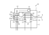
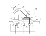
- (A) (b) is sectional drawing for demonstrating operation
- the vehicle V shown in FIG. 1 includes a battery unit B, an inverter unit I, and a motor unit M that are electrically connected by a wire harness W.
- a battery unit B is provided behind the vehicle V, and the inverter unit I and the battery unit B are connected by a wire harness W.
- a connector portion C is provided on a power supply circuit between the battery unit B and the motor unit M as a load.
- the connector plug C is detachably provided with a service plug 10.
- the connector part C of this example has a pair of first terminals C1 constituting a power circuit and a pair of second terminals C2 constituting an interlock circuit for switching on and off the power circuit.
- the service plug 10 includes a main body portion 11 attached to the connector portion C, and a switching lever portion 12 that switches a fixing state between the main body portion 11 and the connector portion C between a locked state and an unlocked state. And have.
- the main body 11 includes a housing 21 and a pair of power bus bars 22 provided in the housing 21.
- the pair of power bus bars 22 is electrically connected to a first terminal C1 provided on the connector part C side, and a power circuit is formed between the battery unit B and the motor unit M.
- the base end portion of the switching lever portion 12 is attached to the main body portion 11 by the rotation pin 31 and can be rotated around the rotation pin 31.
- the switching lever portion 12 has an interlock terminal 32 that can be connected to the second terminal C2 of the connector portion C on the distal end portion side.
- the interlock circuit includes a relay circuit interposed in the power supply circuit, and the power supply circuit is in an open state in a state where the interlock terminal 32 is not electrically connected to the second terminal C2 (non-conductive state). (OFF), and the power supply circuit is closed (ON) when the interlock terminal 32 and the second terminal C2 are electrically connected (conductive state).
- the switching lever portion 12 has an engagement claw portion 33 that engages with the engagement protrusion C3 of the connector portion C in the rotation direction at the distal end portion thereof.
- the engagement claw portion 33 and the engagement protrusion C3 are so-called snap-fit structures, and the rotation of the switching lever portion 12 is restricted by engaging with each other so that the main body portion 11 is held in a fixed state. It has become. That is, the switching lever portion 12 can be switched between a holding state in which the main body portion 11 and the connector portion C are fixed and a release state in which the main body portion 11 can be detached by releasing the holding state. ing.
- a power cutoff unit 13 is provided at the tip of the switching lever unit 12.
- the power shut-off unit 13 has an explosive actuator 41.
- the actuator 41 generates combustion gas by ignition combustion of explosives based on a collision detection signal from a substantially cylindrical cylinder portion 42, a piston portion 43 disposed in a cylinder bore inside the cylinder portion 42, and an impact detection sensor.
- a gas generation unit 44 is provided.
- the cylinder portion 42 has a through hole 42b in one bottom portion 42a of the cylinder bore, and has the gas generating portion 44 in the other bottom portion 42c.
- the piston part 43 has a columnar part 43a and a disk part 43b provided at an end of the columnar part 43a.
- the disc portion 43 b is accommodated in the cylinder bore of the cylinder portion 42 in a state where the columnar portion 43 a is inserted into the through hole 42 b of the cylinder portion 42.
- the diameter of the columnar part 43a is substantially the same as or slightly smaller than the inner diameter of the through hole 42b.
- the diameter of the disc part 43b is substantially the same as the inner diameter of the cylinder part 42, which is larger than the diameter of the columnar part 43a and larger than the inner diameter of the through hole 42b. Thereby, for example, even when the disc portion 43b is close to one bottom portion 42a of the cylinder portion 42, the disc portion 43b having a diameter larger than the through hole 42b contacts the bottom portion 42a. The piston 43 is prevented from dropping from the cylinder bore.
- the gas generating part 44 is attached to the bottom part 42 c so as to be provided between the other bottom part 42 c of the cylinder bore of the cylinder part 42 and the piston part 43.
- the gas generation unit 44 is ignited and burned by an initiator (ignition device) (not shown) based on a collision detection signal S informing that the collision of the vehicle V output from a collision detection sensor (satellite sensor) (not shown) is detected. It has become.
- the collision detection sensor mentioned here includes a determination circuit that determines a collision from acceleration (deceleration) information from the acceleration sensor. When the collision is determined by the determination circuit, the collision detection sensor detects a collision.
- the detection signal S is output to the service plug 10 side.
- the piston part 43 is pressed by the combustion gas generated in association therewith, whereby the piston part 43 has a bottom part 42a having a through hole 42b in the cylinder bore of the cylinder part 42. Move towards the side.
- the switching lever portion 12 moves in a direction away from the connector portion C due to the repulsive force generated by the tip portion of the piston portion 43 (columnar portion 43a) being exposed to the outside and coming into contact with the connector portion C.
- the mechanical contact between the interlock terminal 32 and the second terminal C2 is released, and a non-conduction state is established.
- the relay circuit described above is turned off, the power supply circuit is opened, and a non-conducting state is established.
- the service plug 10 of the present embodiment is attached to the connector part C so that the power bus bar 22 is connected to the first terminal C1 of the connector part C, and the battery unit B is connected to the motor unit M via the inverter unit I.
- a power supply circuit to be connected is configured.
- the power supply circuit is provided with an interlock circuit capable of switching the power supply circuit on and off by turning on and off the relay circuit.
- the relay circuit is turned on and the power supply circuit is turned on, and the second terminal C2 and the service plug 10 are interlocked.
- the relay circuit is turned off and the power supply circuit is opened. Thereby, the power supply from the battery unit B can be cut off.
- the service plug 10 of the present embodiment is provided with a power shut-off unit 13 having an actuator 41 so that the actuator 41 operates based on the collision detection signal S.
- the tip of the columnar portion 43a of the piston portion 43 is in contact with the connector portion C before the actuator 41 is actuated.
- the interlock terminal 32 and the second terminal C2 are electrically connected as shown in FIG.
- the power supply circuit is opened from the battery unit B by bringing the interlock terminal 32 of the switching lever portion 12 into a non-conductive state with the second terminal C2 by the actuator 41 that operates based on the collision detection signal S of the vehicle V.
- the power supply can be cut off.
- safety can be improved.
- the explosive actuator 41 By using the explosive actuator 41, it is possible to quickly cut off the power supply from the battery unit B at the time of a vehicle collision.
- the core wires of the plus-side high-voltage electric wire and the minus-side high-voltage electric wire included in the wire harness W are in direct contact with each other, It is assumed that the core wires of the electric wires are connected to each other through some conductor such as other vehicle components.
- the power supply from the battery unit B is interrupted by the service plug 10 of the present embodiment, a short circuit between the core wires of each electric wire can be suppressed.
- the service plug 10 of the present embodiment includes an intermediate unit 51 having a power shut-off unit 13 between the main body unit 11 and the connector unit C.
- the intermediate unit 51 is provided with a plurality of power cutoff units 13 in the housing 52.
- the attachment structure of the main body 11 to the intermediate unit 51 and the attachment structure of the intermediate unit 51 to the connector C are substantially the same, for example, when the intermediate unit 51 is omitted, the main body 11 is connected to the connector part. It can be attached directly to C.
- an engaging claw portion 52a that engages with an engaging protrusion C3 of the connector portion C and an engaging claw portion 33 of the switching lever portion 12 are engaged with each other in the rotation direction.
- Engaging protrusions 52b are provided in the housing 52 of the intermediate unit 51.
- the switching lever portion 12 is operated to rotate to release the engagement state between the engagement claw portion 33 of the switching lever portion 12 and the engagement protrusion 52 b of the intermediate unit 51.
- the interlock terminal 32 and the second terminal C2 of the connector portion C are brought into a non-conductive state, so that the power supply from the battery unit B is cut off.
- the switching lever portion 12 is grasped and the main body portion 11 is pulled out from the intermediate unit 51.
- the power bus bar 22 of the main body part 11 and the first terminal C1 of the connector part C become non-conductive, the power supply circuit is opened, and the power supply from the battery unit B is reliably cut off. ing.
- the actuator 43 of the power shut-off unit 13 operates so that the piston unit 43 protrudes from the intermediate unit 51 to the connector unit C side.
- the intermediate unit 51 is separated from the connector portion C, whereby the interlock terminal 32 and the second terminal C2 are brought into a non-conductive state, and the power bus bar 22 and the first terminal C1 are brought into a non-conductive state.
- the interlock terminal 32 and the second terminal C2 can be brought into a non-conductive state and the power bus bar 22 and the first terminal C1 can be brought into a non-conductive state, the power supply circuit is reliably opened and the battery unit The power supply from B can be cut off.
- the explosive actuator 41 is used as the power shut-off unit 13, but the present invention is not limited to this.
- the switching lever portion 12 is configured to be rotatable with respect to the main body portion 11 around the rotation pin 31, and the switching lever portion 12 is rotated with the second terminal C2 of the connector portion C by the rotation operation.
- the electrical connection with the interlock terminal 32 is switched between the conductive state and the non-conductive state
- the present invention is not limited to this.
- the electrical connection between the second terminal C2 of the connector portion C and the interlock terminal 32 may be switched between a conductive state and a non-conductive state by sliding the switching lever portion 12.
- the switching lever portion 12 is slid in the direction intersecting the direction in which the main body portion 11 is pulled out from the connector portion C, and after the switching lever portion 12 is slid relative to the main body portion 11, the switching lever portion 12 is moved.
- a configuration may be added in which the main body portion 11 can be pulled out from the connector portion C after rotating.
- An example of such a configuration is a service plug disclosed in, for example, Japanese Patent Application Laid-Open No. 2012-79644.
- the power cutoff by the power cutoff unit 13 is performed based on the collision detection signal S from the collision detection sensor.
- the present invention is not limited to this.
- a configuration may be adopted in which a current input to an inflator initiator (ignition device) is used as a collision detection signal when an airbag mounted on the vehicle V is opened.
- the actuator 41 pops up at least a part of the service plug 10 from the connector part C non-manually, that is, automatically, and releases the electrical connection between the service plug 10 and the connector part C.
- pop-up mechanism Sometimes called pop-up mechanism.
- the service plug 10 (for example, the actuator 41) is configured to receive the collision detection signal S from the collision detection sensor.
- the service plug 10 can include a signal line for connecting the collision detection sensor and the actuator 41 (for example, the gas generation unit 44).
- the collision detection signal S is supplied to the actuator 41 through the signal line.
- the switching lever portion 12 can include the signal line, as shown in FIG. 4, and in some other non-limiting examples, as shown in FIG.
- the intermediate unit 51 can include the signal line.
- the pair of first terminals C1 of the connector part C may be referred to as a power supply circuit or a first pair of fixed contacts.
- the pair of second terminals C2 of the connector C may be referred to as an interlock circuit or a second pair of fixed contacts.
- the power bus bar 22 of the service plug 10 may be referred to as a movable contact of the power circuit.
- the interlock terminal 32 of the service plug 10 may be referred to as a movable contact of the interlock circuit.
- the switching lever portion 12 allows the operator to turn the lever portion 12 with respect to the main body portion 11 with a finger or hand, and holds the lever portion 12 with a finger or hand to move the lever portion 12 and the main body portion 11 together. It is configured so that it can be pulled upward.
- the switching lever part 12 may be called a lever knob or a lever handle.
- Some implementation examples include a service plug that can be attached to and detached from a connector portion (C) disposed on a power circuit between a battery (B) and a load (M) of a vehicle (V). 10), when the service plug (10) is attached to the connector portion (C), the power supply circuit is closed via the service plug (10), and the service plug (10) is connected to the connector.
- the service plug (10) configured to open the power supply circuit when removed from the section (C) is provided.
- the service plug (10) includes an actuator (41) configured to receive a collision detection signal (S) indicating a collision event of the vehicle (V), and the actuator (41) includes the collision detection signal.
- At least a part of the service plug (10) is automatically popped up from the connector part (C), and electrical connection between the service plug (10) and the connector part (C) is established.
- a pop-up mechanism (42, 43, 44) for releasing is provided.
- a service plug (10) is provided for use with a connector part (C) including a fixed contact (C2).
- the service plug (10) includes a main body portion (11) and a lever portion (12) rotatably supported by the main body portion (11), and the main body portion (11) includes the service plug (11).
- a power bus bar (10) that is electrically connected to the first pair of fixed contacts (C1) provided in the first portion of the connector portion (C) when the connector portion (C) is attached. 22).
- the lever portion (12) includes a second pair of fixed contacts (provided in a second portion of the connector portion (C) when the service plug (10) is attached to the connector portion (C)).
- the service plug (10) further includes an actuator (41) configured to receive a collision detection signal (S) indicating a collision event of the vehicle (V), the actuator (41) being configured to detect the collision.
- S collision detection signal
- the lever part (12) of the service plug (10) is automatically popped up from the second part of the connector part (C), and the service plug (10)
- a pop-up mechanism (42, 43, 44) for releasing the electrical connection between the interlock terminal (32) and the second pair of fixed contacts (C2) of the connector portion (C) is provided.
- the pop-up mechanism (42, 43, 44) With the main body portion (11) of the service plug (10) disposed in the first portion of the connector portion (C), the lever portion (12) is rotated with respect to the main body portion (11). And configured to automatically pop up only the lever portion (12) of the service plug (10) from the second portion of the connector portion (C).
- the pop-up mechanism (42, 43, 44) automatically pops up the lever portion (12) and the main body portion (11) from the connector portion (C). Composed.
- the pop-up mechanism (42, 43, 44) is provided in the lever portion (12).
- the service plug (10) includes the body portion (11), the lever portion (12), the first portion of the connector portion (C), and the second portion.
- the intermediate unit (51) further includes an intermediate unit (51) sandwiched between the power bus bar (22) and the interlock terminal (32) through the intermediate unit (51).
- the pop-up mechanism (42, 43, 44) is configured to be electrically connected to the first pair of fixed contacts (C1) and the second pair of fixed contacts (C2), respectively. (51).
- the service plug (10) includes a signal line for supplying the collision detection signal (S) to the actuator (41).
- the pop-up mechanism (42, 43, 44) includes a gas generator (44) and the service plug (10) according to the gas pressure generated by the gas generator (44). And a piston (43).
- the piston (43) includes a piston head (43b) that receives a gas pressure generated by the gas generation unit (44), and the piston (43) performs the protruding stroke. And a leg portion (43a) for pushing the connector portion (C).
Landscapes
- Engineering & Computer Science (AREA)
- Mechanical Engineering (AREA)
- Life Sciences & Earth Sciences (AREA)
- Sustainable Development (AREA)
- Sustainable Energy (AREA)
- Power Engineering (AREA)
- Transportation (AREA)
- Physics & Mathematics (AREA)
- Fluid Mechanics (AREA)
- Details Of Connecting Devices For Male And Female Coupling (AREA)
Abstract
サービスプラグ10は、コネクタ部Cの第1端子C1と接続されて電源回路に接続される一対のパワーバスバー22を有する本体部11と、コネクタ部Cの第2端子C2と導通状態で電源回路を閉状態とし、コネクタ部Cの第2端子C2と非導通状態で電源回路を開状態とするインターロック端子32を有する切り換えレバー部12と、車両Vの衝突検知信号Sに基づいて動作するアクチュエータ41により切り換えレバー部12のインターロック端子32を第2端子C2と非導通状態として電源回路を開状態とする電源遮断部13と、を備える。
Description
本発明は、サービスプラグに関するものである。
従来、ハイブリッド車や電気自動車等の車両には、バッテリと負荷との間の電源回路を遮断するための電源回路遮断装置としてサービスプラグが知られている(例えば特許文献1参照)。
このようなサービスプラグは、車両のメンテナンスや修理などの作業の安全性を確保するために、作業時に電源回路からサービスプラグを取り外すことでバッテリと負荷との間の電源回路を遮断するように構成されている。
このようなサービスプラグは、人が操作可能なレバーにインターロック端子を設け、コネクタ部(特許文献1では待受側ハウジング)の端子に接続することで電源回路を閉状態とし、インターロック端子とコネクタ部の端子とを離間させることで電源回路を開状態としてバッテリからの電力供給を遮断するようになっている。
ところで、上記のようなサービスプラグでは、例えば車両衝突時等には救助者が切り換えレバー部を操作してインターロック用端子とコネクタ部の端子との電気的接続を解除することでバッテリからの電力供給を遮断することが可能となっている。しかしながら、車両衝突時には、例えば高圧バッテリからの高圧回路が傷つきショートすると、漏電などの問題が発生する懸念があることから、サービスプラグを手動で操作すること自体が危険なことがあるため、安全性の向上が望まれている。
本発明は、上記課題を解決するためになされたものであって、その目的は、安全性を向上できるサービスプラグを提供することにある。
上記課題を解決するサービスプラグは、車両のバッテリと負荷との間の電源回路上に配置されたコネクタ部に対して着脱可能なサービスプラグであって、前記コネクタ部の第1端子と接続されて前記電源回路に接続される一対のパワーバスバーを有する本体部と、前記コネクタ部の第2端子と導通状態で前記電源回路を閉状態とし、前記コネクタ部の前記第2端子と非導通状態で前記電源回路を開状態とするインターロック端子を有する切り換えレバー部と、前記車両の衝突検知信号に基づいて動作するアクチュエータにより少なくとも前記切り換えレバー部の前記インターロック端子を前記第2端子と非導通状態として前記電源回路を開状態とする電源遮断部と、を備える。
この構成によれば、車両の衝突検知信号に基づいて動作するアクチュエータにより切り換えレバー部の前記インターロック端子を第2端子と非導通状態とすることで電源回路を開状態としてバッテリからの電力供給を遮断することができる。このように車両衝突時においてアクチュエータの動作によってバッテリからの電力供給を遮断することができるため、安全性を向上できる。
上記サービスプラグにおいて、前記切り換えレバー部は、前記本体部に対して回動動作により、前記本体部と前記コネクタ部との固定状態で保持する保持状態と、前記保持状態を解除して前記本体部を取り外し可能な解除状態とに切り換えるものであり、前記電源遮断部は、前記アクチュエータにより、前記解除状態とすることで前記切り換えレバー部のインターロック端子を前記第2端子と非導通状態として前記電源回路を開状態とすることが好ましい。
この構成によれば、アクチュエータにより切り換えレバー部が解除状態とすることでインターロック端子と第2端子とが非導通状態となって電源回路を開状態とされるため、車両衝突時においてサービスプラグをコネクタ部から容易に取り外すことができる。
上記サービスプラグにおいて、前記電源遮断部は、前記本体部と前記コネクタ部との間に設けられて、前記アクチュエータにより前記切り換えレバー部のインターロック端子を前記第2端子と非導通状態とするとともに前記パワーバスバーを前記第1端子と非導通状態として前記電源回路を開状態とすることが好ましい。
この構成によれば、インターロック端子と第2端子とを非導通状態とするとともにパワーバスバーと第1端子とを非導通状態とすることができるため、電源回路を確実に開状態としてバッテリからの電力供給を遮断することができる。
上記サービスプラグにおいて、前記電源遮断部の前記アクチュエータは、前記衝突検知信号に基づき作動する火薬式のアクチュエータであることが好ましい。
この構成によれば、火薬式のアクチュエータを用いることで車両衝突時のバッテリからの電力供給を素早く遮断することが可能となる。
この構成によれば、火薬式のアクチュエータを用いることで車両衝突時のバッテリからの電力供給を素早く遮断することが可能となる。
本発明のサービスプラグによれば、安全性を向上できる。
(第1実施形態)
以下、サービスプラグの第1実施形態について、図面に従って説明する。なお、各図面では、説明の便宜上、構成の一部を誇張又は簡略化して示す場合がある。また、各部分の寸法比率についても、実際と異なる場合がある。
以下、サービスプラグの第1実施形態について、図面に従って説明する。なお、各図面では、説明の便宜上、構成の一部を誇張又は簡略化して示す場合がある。また、各部分の寸法比率についても、実際と異なる場合がある。
図1に示す車両Vは、ワイヤハーネスWによって電気的に接続されるバッテリユニットBとインバータユニットIとモータユニットMを備える。本例では車両Vの前方にインバータユニットI及びモータユニットMが設けられ、インバータユニットIとモータユニットMとがワイヤハーネスWによって接続される。また、車両Vの後方にバッテリユニットBが設けられ、インバータユニットIとバッテリユニットBとがワイヤハーネスWによって接続される。
バッテリユニットBにおいて、バッテリユニットBと負荷としてのモータユニットMとの間の電源回路上にコネクタ部Cが設けられる。コネクタ部Cにはサービスプラグ10が着脱可能に設けられる。本例のコネクタ部Cは、電源回路を構成する一対の第1端子C1と、前記電源回路のオンオフを切り換えるインターロック回路を構成する一対の第2端子C2とを有する。
図2に示すように、サービスプラグ10は、コネクタ部Cに対して取り付けられる本体部11と、本体部11とコネクタ部Cとの固定状態をロック状態とアンロック状態とに切り換える切り換えレバー部12とを有する。
本体部11は、ハウジング21と、該ハウジング21内に設けられる一対のパワーバスバー22とを有する。一対のパワーバスバー22は、前記コネクタ部C側に設けられた第1端子C1と電気的に接続されてバッテリユニットBとモータユニットMとの間に電源回路が形成される。
切り換えレバー部12は、その基端部が回動ピン31によって本体部11に対して取り付けられ、回動ピン31を中心として回動可能となっている。切り換えレバー部12は、その先端部側にコネクタ部Cの第2端子C2と接続可能なインターロック端子32を有する。ここで、インターロック回路は、前記電源回路中に介在されるリレー回路を有し、前記インターロック端子32が前記第2端子C2と導通されていない状態(非導通状態)で電源回路が開状態(オフ)となり、インターロック端子32と第2端子C2とが導通された状態(導通状態)で電源回路が閉状態(オン)となる。
また、切り換えレバー部12は、その先端部にコネクタ部Cの係合突部C3と回動方向において係合する係合爪部33を有する。係合爪部33と係合突部C3とは、所謂スナップフィット構造であって、互いに係合することで切り換えレバー部12の回動を規制し、本体部11を固定状態で保持するようになっている。すなわち、切り換えレバー部12は、本体部11とコネクタ部Cとの固定状態で保持する保持状態と、保持状態を解除して本体部11を取り外し可能な解除状態とに切り換えることができるようになっている。
また、本実施形態のサービスプラグ10は、切り換えレバー部12の先端部に電源遮断部13が設けられる。
図2~図4(a)(b)に示すように、電源遮断部13は、火薬式のアクチュエータ41を有している。アクチュエータ41は、略円筒状のシリンダ部42と、シリンダ部42の内部のシリンダボアに配設されたピストン部43と、衝撃検知センサからの衝突検知信号に基づき火薬の着火燃焼によって燃焼ガスを発生させるガス発生部44とを有する。
図2~図4(a)(b)に示すように、電源遮断部13は、火薬式のアクチュエータ41を有している。アクチュエータ41は、略円筒状のシリンダ部42と、シリンダ部42の内部のシリンダボアに配設されたピストン部43と、衝撃検知センサからの衝突検知信号に基づき火薬の着火燃焼によって燃焼ガスを発生させるガス発生部44とを有する。
シリンダ部42は、シリンダボアの一方の底部42aに貫通孔42bが設けられ、他方の底部42cに前記ガス発生部44を有する。
ピストン部43は、柱状部43aと、柱状部43aの端部に設けられる円板部43bとを有する。ピストン部43は、柱状部43aがシリンダ部42の貫通孔42bに挿通された状態で、前記円板部43bがシリンダ部42のシリンダボアに収容されている。柱状部43aの直径は、貫通孔42bの内径と略同じ又はやや小さくなっている。円板部43bの直径は、シリンダ部42の内径と略同じとされ、柱状部43aの直径よりも大きく、貫通孔42bの内径よりも大きくなっている。これにより、例えば円板部43bがシリンダ部42の一方の底部42aに近接した場合であっても、貫通孔42bよりも大径の円板部43bが底部42aと当接するため、シリンダ部42のシリンダボアからピストン部43が脱落することが抑えられている。
ピストン部43は、柱状部43aと、柱状部43aの端部に設けられる円板部43bとを有する。ピストン部43は、柱状部43aがシリンダ部42の貫通孔42bに挿通された状態で、前記円板部43bがシリンダ部42のシリンダボアに収容されている。柱状部43aの直径は、貫通孔42bの内径と略同じ又はやや小さくなっている。円板部43bの直径は、シリンダ部42の内径と略同じとされ、柱状部43aの直径よりも大きく、貫通孔42bの内径よりも大きくなっている。これにより、例えば円板部43bがシリンダ部42の一方の底部42aに近接した場合であっても、貫通孔42bよりも大径の円板部43bが底部42aと当接するため、シリンダ部42のシリンダボアからピストン部43が脱落することが抑えられている。
ガス発生部44は、シリンダ部42のシリンダボアの他方の底部42cとピストン部43との間に設けられるようにして底部42cに取り付けられている。ガス発生部44は、図示しない衝突検知センサ(サテライトセンサ)から出力される車両Vの衝突を検知した旨を知らせる衝突検知信号Sに基づき、図示しないイニシエータ(点火装置)によって着火燃焼されるようになっている。なお、ここで言う衝突検知センサは、加速度センサからの加速度(減速度)情報から衝突を判定する判定回路を含んでおり、該判定回路にて衝突と判定された場合に衝突検知センサからの衝突検知信号Sがサービスプラグ10側に出力されるようになっている。
そして、ガス発生部44において火薬が着火燃焼すると、これに伴って発生する燃焼ガスによってピストン部43が押圧されることにより、同ピストン部43がシリンダ部42のシリンダボアにおいて貫通孔42bを有する底部42a側に向けて移動するようになる。これにより、ピストン部43(柱状部43a)の先端部は更に外部に露出してコネクタ部Cと当接することで発生する反発力によって切り換えレバー部12がコネクタ部Cから離間する方向に動作してインターロック端子32と、第2端子C2との機械的接触が解除されて非導通状態となる。これによって、前述したリレー回路がオフとなって電源回路が開放されて非導通状態となる。
次に、本実施形態の作用について説明する。
本実施形態のサービスプラグ10は、コネクタ部Cに対して取り付けることでコネクタ部Cの第1端子C1に対してパワーバスバー22が接続され、バッテリユニットBをインバータユニットIを介してモータユニットMと接続する電源回路が構成される。また、電源回路中にはリレー回路のオンオフによって前記電源回路のオンオフを切り換え可能なインターロック回路が設けられる。コネクタ部Cの第2端子C2とサービスプラグ10のインターロック端子32とが接続されることでリレー回路がオン状態となって電源回路をオン状態とし、第2端子C2とサービスプラグ10のインターロック端子32とが非接続となることでリレー回路がオフ状態となって電源回路が開状態となる。これによって、バッテリユニットBからの電力供給を遮断することができる。
本実施形態のサービスプラグ10は、コネクタ部Cに対して取り付けることでコネクタ部Cの第1端子C1に対してパワーバスバー22が接続され、バッテリユニットBをインバータユニットIを介してモータユニットMと接続する電源回路が構成される。また、電源回路中にはリレー回路のオンオフによって前記電源回路のオンオフを切り換え可能なインターロック回路が設けられる。コネクタ部Cの第2端子C2とサービスプラグ10のインターロック端子32とが接続されることでリレー回路がオン状態となって電源回路をオン状態とし、第2端子C2とサービスプラグ10のインターロック端子32とが非接続となることでリレー回路がオフ状態となって電源回路が開状態となる。これによって、バッテリユニットBからの電力供給を遮断することができる。
また、本実施形態のサービスプラグ10は、アクチュエータ41を有する電源遮断部13が設けられ、衝突検知信号Sに基づいてアクチュエータ41が動作するようになっている。
図4(a)に示すように、アクチュエータ41の作動前においては、ピストン部43の柱状部43aの先端部がコネクタ部Cと当接している。このとき、インターロック端子32と第2端子C2とは図1に示すように、電気的に接続された状態となっている。
図4(b)に示すように、アクチュエータ41が作動すると、前記ピストン部43の円板部43bが底部42a側に押圧されて近接するように移動するようになる。このため、ピストン部43の柱状部43aが更に外部に露出するように動作することで、ピストン部43とコネクタ部Cとの間で反発力が発生する。この反発力により、切り換えレバー部12の係合爪部33とコネクタ部Cの係合突部C3との係合状態が解除され、図2に示すようにコネクタ部Cから切り換えレバー部12が離間するように回動動作し、インターロック端子32と第2端子C2とが離間されてインターロック端子32と第2端子C2とが非導通状態となる。これによって電源回路が開状態となってバッテリユニットBからの電力供給が遮断されるようになっている。
次に、本実施形態の効果を記載する。
(1)車両Vの衝突検知信号Sに基づいて動作するアクチュエータ41により切り換えレバー部12のインターロック端子32を第2端子C2と非導通状態とすることで電源回路を開状態としてバッテリユニットBからの電力供給を遮断することができる。このように車両衝突時においてアクチュエータ41の動作によってバッテリユニットBからの電力供給を遮断することができるため、安全性を向上できる。
(1)車両Vの衝突検知信号Sに基づいて動作するアクチュエータ41により切り換えレバー部12のインターロック端子32を第2端子C2と非導通状態とすることで電源回路を開状態としてバッテリユニットBからの電力供給を遮断することができる。このように車両衝突時においてアクチュエータ41の動作によってバッテリユニットBからの電力供給を遮断することができるため、安全性を向上できる。
(2)アクチュエータ41により切り換えレバー部12が解除状態とすることでインターロック端子32と第2端子C2とが非導通状態となって電源回路を開状態とされるため、車両衝突時においてサービスプラグ10をコネクタ部Cから容易に取り外すことができる。
(3)火薬式のアクチュエータ41を用いることで車両衝突時のバッテリユニットBからの電力供給を素早く遮断することが可能となる。
(4)車両衝突時の衝撃によって、ワイヤハーネスWに含まれるプラス側高圧電線とマイナス側高圧電線との芯線同士が直接的に接触、又は、前記各電線が挿通されるシールドパイプの破断片やそれ以外の車両構成部品等、何らかの導体を介して各電線の芯線同士が接続されることが想定される。しかしながら、本実施形態のサービスプラグ10によってバッテリユニットBからの電力供給が遮断されるため、各電線の芯線同士の短絡を抑制できる。
(4)車両衝突時の衝撃によって、ワイヤハーネスWに含まれるプラス側高圧電線とマイナス側高圧電線との芯線同士が直接的に接触、又は、前記各電線が挿通されるシールドパイプの破断片やそれ以外の車両構成部品等、何らかの導体を介して各電線の芯線同士が接続されることが想定される。しかしながら、本実施形態のサービスプラグ10によってバッテリユニットBからの電力供給が遮断されるため、各電線の芯線同士の短絡を抑制できる。
(第2実施形態)
以下に、サービスプラグの第2実施形態について、図面に従って説明する。なお、図面では、説明の便宜上、構成の一部を誇張又は簡略化して示す場合がある。また、各部分の寸法比率についても、実際と異なる場合がある。また、本実施形態において、上記第1実施形態と同様の構成については、同一の符号を付して、その詳細な説明の一部又は全部を省略する。
以下に、サービスプラグの第2実施形態について、図面に従って説明する。なお、図面では、説明の便宜上、構成の一部を誇張又は簡略化して示す場合がある。また、各部分の寸法比率についても、実際と異なる場合がある。また、本実施形態において、上記第1実施形態と同様の構成については、同一の符号を付して、その詳細な説明の一部又は全部を省略する。
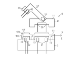
図5に示すように、本実施形態のサービスプラグ10は、本体部11とコネクタ部Cとの間に電源遮断部13を有する中間ユニット51を有する。
中間ユニット51には、ハウジング52内に複数の電源遮断部13が設けられる。本例では、本体部11の中間ユニット51との取付構造と、中間ユニット51のコネクタ部Cとの取付構造が略同じであるため、例えば中間ユニット51を省略した場合に本体部11をコネクタ部Cに直接取り付けることが可能となっている。中間ユニット51のハウジング52には、その端部にコネクタ部Cの係合突部C3と係合する係合爪部52aと、切り換えレバー部12の係合爪部33が回動方向において係合する係合突部52bとが設けられる。
中間ユニット51には、ハウジング52内に複数の電源遮断部13が設けられる。本例では、本体部11の中間ユニット51との取付構造と、中間ユニット51のコネクタ部Cとの取付構造が略同じであるため、例えば中間ユニット51を省略した場合に本体部11をコネクタ部Cに直接取り付けることが可能となっている。中間ユニット51のハウジング52には、その端部にコネクタ部Cの係合突部C3と係合する係合爪部52aと、切り換えレバー部12の係合爪部33が回動方向において係合する係合突部52bとが設けられる。
次に、本実施形態のサービスプラグ10のメンテナンス時における取り外し工程について説明する。
図6に示すように、切り換えレバー部12を回動するように操作して切り換えレバー部12の係合爪部33と中間ユニット51の係合突部52bとの係合状態を解除する。これによってインターロック端子32とコネクタ部Cの第2端子C2とが非導通状態となって、バッテリユニットBからの電力供給が遮断されるようになっている。
図6に示すように、切り換えレバー部12を回動するように操作して切り換えレバー部12の係合爪部33と中間ユニット51の係合突部52bとの係合状態を解除する。これによってインターロック端子32とコネクタ部Cの第2端子C2とが非導通状態となって、バッテリユニットBからの電力供給が遮断されるようになっている。
図7に示すように、切り換えレバー部12を把持して本体部11を中間ユニット51から引き抜く。これにより、本体部11のパワーバスバー22とコネクタ部Cの第1端子C1とが非導通状態となって、電源回路が開放されてバッテリユニットBからの電力供給が確実に遮断されるようになっている。
上述したようにメンテナンス等で作業者がサービスプラグ10を取り外す場合には本体部11と中間ユニット51とが分離するようになっている。
次に、本実施形態のサービスプラグ10の車両衝突時における電力供給の遮断について説明する。
次に、本実施形態のサービスプラグ10の車両衝突時における電力供給の遮断について説明する。
図8に示すように、サービスプラグ10に入力される衝突検知信号Sに基づき、電源遮断部13のアクチュエータ41によりピストン部43が中間ユニット51からコネクタ部C側に飛び出すように動作することで、中間ユニット51がコネクタ部Cから分離する、これにより、インターロック端子32と第2端子C2とが非導通状態となるとともに、パワーバスバー22と第1端子C1とが非導通状態となる。
本実施形態では、上記実施形態の(1)、(3)及び(4)の効果に加えて以下の効果を奏する。
(5)インターロック端子32と第2端子C2とを非導通状態とするとともにパワーバスバー22と第1端子C1とを非導通状態とすることができるため、電源回路を確実に開状態としてバッテリユニットBからの電力供給を遮断することができる。
(5)インターロック端子32と第2端子C2とを非導通状態とするとともにパワーバスバー22と第1端子C1とを非導通状態とすることができるため、電源回路を確実に開状態としてバッテリユニットBからの電力供給を遮断することができる。
なお、上記各実施形態は、以下のように変更してもよい。
・上記各実施形態では、電源遮断部13として火薬式のアクチュエータ41を用いる構成としたが、これに限らない。例えばプッシュソレノイドを用いてピストン部を動作させる機構を採用してもよい。
・上記各実施形態では、電源遮断部13として火薬式のアクチュエータ41を用いる構成としたが、これに限らない。例えばプッシュソレノイドを用いてピストン部を動作させる機構を採用してもよい。
・上記各実施形態では、切り換えレバー部12を回動ピン31を中心として本体部11に対して回動可能な構成として、切り換えレバー部12に回動動作によってコネクタ部Cの第2端子C2とインターロック端子32との電気的接続を導通状態と非導通状態とで切り換える構成としたが、これに限らない。例えば、切り換えレバー部12をスライドさせることでコネクタ部Cの第2端子C2とインターロック端子32との電気的接続を導通状態と非導通状態とで切り換える構成としてもよい。このような構成において、切り換えレバー部12のスライド方向は本体部11をコネクタ部Cから引き抜く方向と交差する方向とし、切り換えレバー部12を本体部11に対してスライドさせた後に、切り換えレバー部12を回動させた後に本体部11をコネクタ部Cから引き抜き可能な構成を付加してもよい。このような構成の一例としては例えば特開2012-79644号公報で開示されているサービスプラグがある。
・上記各実施形態では、衝突検知センサからの衝突検知信号Sに基づき電源遮断部13による電力遮断を実施する構成としたが、これに限らない。例えば車両Vに搭載されるエアバッグの開動作の際にインフレータのイニシエータ(点火装置)に入力される電流を衝突検知信号として用いる構成を採用してもよい。
・アクチュエータ41は、衝突検知信号Sに応答してサービスプラグ10の少なくとも一部をコネクタ部Cから非手動ですなわち自動でポップアップさせて、サービスプラグ10とコネクタ部Cとの電気的接続を解除するポップアップ機構と呼称することがある。
・各実施形態において、サービスプラグ10(例えばアクチュエータ41)は、衝突検知センサからの衝突検知信号Sを受信するように構成される。例えば、サービスプラグ10は、衝突検知センサとアクチュエータ41(例えばガス発生部44)とを接続するための信号線を備えることができる。当該信号線によって衝突検知信号Sがアクチュエータ41に供給される。いくつかの非限定的な例では、図4に示すように、切り換えレバー部12が当該信号線を含むことができ、別のいくつかの非限定的な例では、図5に示すように、中間ユニット51が当該信号線を含むことができる。
・コネクタ部Cの一対の第1端子C1は、電源回路のまたは第1の一対の固定接点と呼称することがある。コネクタ部Cの一対の第2端子C2は、インターロック回路のまたは第2の一対の固定接点と呼称することがある。サービスプラグ10のパワーバスバー22は電源回路の可動接点と呼称することがある。サービスプラグ10のインターロック端子32はインターロック回路の可動接点と呼称することがある。
・切り換えレバー部12は、作業者が指または手で当該レバー部12を本体部11に対して回動でき、当該レバー部12を指または手で保持して当該レバー部12及び本体部11を上方に引くことができるように構成される。切り換えレバー部12は、レバーノブまたはレバーハンドルと呼称することがある。
・上記各実施形態並びに各変形例は適宜組み合わせてもよい。
本開示は以下の実装例を包含する。限定のためでなく理解の補助として実施形態の構成要素の参照符号を付した。
本開示は以下の実装例を包含する。限定のためでなく理解の補助として実施形態の構成要素の参照符号を付した。
[付記1]いくつかの実装例は、車両(V)のバッテリ(B)と負荷(M)との間の電源回路上に配置されたコネクタ部(C)に対して着脱可能なサービスプラグ(10)であって、前記サービスプラグ(10)が前記コネクタ部(C)に取り付けられたときに前記サービスプラグ(10)を介して前記電源回路が閉じられ、前記サービスプラグ(10)が前記コネクタ部(C)から取り外されたときに前記電源回路が開くように構成された前記サービスプラグ(10)を提供する。前記サービスプラグ(10)は、前記車両(V)の衝突イベントを示す衝突検知信号(S)を受信するように構成されるアクチュエータ(41)を備え、前記アクチュエータ(41)は、前記衝突検知信号(S)に応答して前記サービスプラグ(10)の少なくとも一部を前記コネクタ部(C)から自動でポップアップさせて、前記サービスプラグ(10)と前記コネクタ部(C)との電気的接続を解除するポップアップ機構(42,43,44)を備える。
[付記2]いくつかの実装例は、車両(V)の電源回路に含まれる第1の一対の固定接点(C1)と、前記車両(V)のインターロック回路に含まれる第2の一対の固定接点(C2)とを含むコネクタ部(C)とともに使用されるサービスプラグ(10)を提供する。前記サービスプラグ(10)は、本体部(11)と、前記本体部(11)に回動可能に支持されるレバー部(12)とを備え、前記本体部(11)は、前記サービスプラグ(10)が前記コネクタ部(C)に取り付けられたときに前記コネクタ部(C)の第1の部分に設けられる前記第1の一対の固定接点(C1)と電気的に接続されるパワーバスバー(22)を含む。前記レバー部(12)は、前記サービスプラグ(10)が前記コネクタ部(C)に取り付けられたときに前記コネクタ部(C)の第2の部分に設けられる前記第2の一対の固定接点(C2)と電気的に接続されるインターロック端子(32)を含む。前記サービスプラグ(10)は、前記車両(V)の衝突イベントを示す衝突検知信号(S)を受信するように構成されるアクチュエータ(41)を更に備え、前記アクチュエータ(41)は、前記衝突検知信号(S)に応答して前記サービスプラグ(10)の少なくとも前記レバー部(12)を前記コネクタ部(C)の前記第2の部分から自動でポップアップさせて、前記サービスプラグ(10)の前記インターロック端子(32)と前記コネクタ部(C)の前記第2の一対の固定接点(C2)との電気的接続を解除するポップアップ機構(42,43,44)を備える。
[付記3]いくつかの実装例では、前記ポップアップ機構(42,43,44)は、
前記サービスプラグ(10)の前記本体部(11)が前記コネクタ部(C)の前記第1の部分に配置された状態で、前記レバー部(12)を前記本体部(11)に対して回動させて、前記サービスプラグ(10)の前記レバー部(12)のみを前記コネクタ部(C)の前記第2の部分から自動でポップアップさせるように構成される。
前記サービスプラグ(10)の前記本体部(11)が前記コネクタ部(C)の前記第1の部分に配置された状態で、前記レバー部(12)を前記本体部(11)に対して回動させて、前記サービスプラグ(10)の前記レバー部(12)のみを前記コネクタ部(C)の前記第2の部分から自動でポップアップさせるように構成される。
[付記4]いくつかの実装例では、前記ポップアップ機構(42,43,44)は、前記レバー部(12)及び前記本体部(11)を前記コネクタ部(C)から自動でポップアップさせるように構成される。
[付記5]いくつかの実装例では、前記ポップアップ機構(42,43,44)は、前記レバー部(12)に設けられる。
[付記6]いくつかの実装例では、前記サービスプラグ(10)は、前記本体部(11)及び前記レバー部(12)と前記コネクタ部(C)の前記第1の部分及び前記第2の部分との間に挟まれる中間ユニット(51)を更に備え、前記中間ユニット(51)は、前記パワーバスバー(22)及び前記インターロック端子(32)が当該中間ユニット(51)を通過して前記第1の一対の固定接点(C1)及び前記第2の一対の固定接点(C2)とそれぞれ電気的に接続されるように構成され、前記ポップアップ機構(42,43,44)は、前記中間ユニット(51)に設けられる。
[付記6]いくつかの実装例では、前記サービスプラグ(10)は、前記本体部(11)及び前記レバー部(12)と前記コネクタ部(C)の前記第1の部分及び前記第2の部分との間に挟まれる中間ユニット(51)を更に備え、前記中間ユニット(51)は、前記パワーバスバー(22)及び前記インターロック端子(32)が当該中間ユニット(51)を通過して前記第1の一対の固定接点(C1)及び前記第2の一対の固定接点(C2)とそれぞれ電気的に接続されるように構成され、前記ポップアップ機構(42,43,44)は、前記中間ユニット(51)に設けられる。
[付記7]いくつかの実装例では、前記サービスプラグ(10)は、前記衝突検知信号(S)を前記アクチュエータ(41)に供給するための信号線を備える。
[付記8]いくつかの実装例では、前記ポップアップ機構(42,43,44)は、ガス発生部(44)と、前記ガス発生部(44)によって発生したガス圧力によって前記サービスプラグ(10)をポップアップさせる突出ストロークを行いピストン(43)とを備える。
[付記8]いくつかの実装例では、前記ポップアップ機構(42,43,44)は、ガス発生部(44)と、前記ガス発生部(44)によって発生したガス圧力によって前記サービスプラグ(10)をポップアップさせる突出ストロークを行いピストン(43)とを備える。
[付記9]いくつかの実装例では、前記ピストン(43)は、前記ガス発生部(44)によって発生したガス圧力を受けるピストンヘッド(43b)と、前記ピストン(43)が前記突出ストロークを行ったときに前記コネクタ部(C)を押す脚部(43a)とを備える。
本発明がその技術的思想から逸脱しない範囲で他の特有の形態で具体化されてもよいということは当業者にとって明らかであろう。例えば、実施形態(あるいはその1つ又は複数の態様)において説明した部品のうちの一部を省略したり、いくつかの部品を組合せてもよい。本発明の範囲は、添付の請求の範囲を参照して、請求の範囲が権利を与えられる均等物の全範囲と共に確定されるべきである。
10…サービスプラグ
11…本体部
12…切り換えレバー部
13…電源遮断部
22…パワーバスバー
32…インターロック端子
41…アクチュエータ
B…バッテリユニット(バッテリ)
C…コネクタ部
C1…第1端子
C2…第2端子
M…モータ(負荷)
S…衝突検知信号
V…車両
11…本体部
12…切り換えレバー部
13…電源遮断部
22…パワーバスバー
32…インターロック端子
41…アクチュエータ
B…バッテリユニット(バッテリ)
C…コネクタ部
C1…第1端子
C2…第2端子
M…モータ(負荷)
S…衝突検知信号
V…車両
Claims (4)
- 車両のバッテリと負荷との間の電源回路上に配置されたコネクタ部に対して着脱可能なサービスプラグであって、
前記コネクタ部の第1端子と接続されて前記電源回路に接続される一対のパワーバスバーを有する本体部と、
前記コネクタ部の第2端子と導通状態で前記電源回路を閉状態とし、前記コネクタ部の前記第2端子と非導通状態で前記電源回路を開状態とするインターロック端子を有する切り換えレバー部と、
前記車両の衝突検知信号に基づいて動作するアクチュエータにより少なくとも前記切り換えレバー部の前記インターロック端子を前記第2端子と非導通状態として前記電源回路を開状態とする電源遮断部と、
を備えることを特徴とするサービスプラグ。 - 請求項1に記載のサービスプラグにおいて、
前記切り換えレバー部は、前記本体部に対して回動動作により、前記本体部と前記コネクタ部との固定状態で保持する保持状態と、前記保持状態を解除して前記本体部を取り外し可能な解除状態とに切り換えるものであり、
前記電源遮断部は、前記アクチュエータにより、前記解除状態とすることで前記切り換えレバー部の前記インターロック端子を前記第2端子と非導通状態として前記電源回路を開状態とすることを特徴とするサービスプラグ。 - 請求項1に記載のサービスプラグにおいて、
前記電源遮断部は、前記本体部と前記コネクタ部との間に設けられて、前記アクチュエータにより前記切り換えレバー部の前記インターロック端子を前記第2端子と非導通状態とするとともに前記パワーバスバーを前記第1端子と非導通状態として前記電源回路を開状態とすることを特徴とするサービスプラグ。 - 請求項2又は3に記載のサービスプラグにおいて、
前記電源遮断部の前記アクチュエータは、前記衝突検知信号に基づき作動する火薬式のアクチュエータであることを特徴とするサービスプラグ。
Priority Applications (2)
| Application Number | Priority Date | Filing Date | Title |
|---|---|---|---|
| CN201880018308.5A CN110419090B (zh) | 2017-03-17 | 2018-02-27 | 服务插头 |
| US16/492,010 US10811822B2 (en) | 2017-03-17 | 2018-02-27 | Service plug |
Applications Claiming Priority (2)
| Application Number | Priority Date | Filing Date | Title |
|---|---|---|---|
| JP2017053210A JP6705406B2 (ja) | 2017-03-17 | 2017-03-17 | サービスプラグ |
| JP2017-053210 | 2017-03-17 |
Publications (1)
| Publication Number | Publication Date |
|---|---|
| WO2018168445A1 true WO2018168445A1 (ja) | 2018-09-20 |
Family
ID=63522162
Family Applications (1)
| Application Number | Title | Priority Date | Filing Date |
|---|---|---|---|
| PCT/JP2018/007273 Ceased WO2018168445A1 (ja) | 2017-03-17 | 2018-02-27 | サービスプラグ |
Country Status (4)
| Country | Link |
|---|---|
| US (1) | US10811822B2 (ja) |
| JP (1) | JP6705406B2 (ja) |
| CN (1) | CN110419090B (ja) |
| WO (1) | WO2018168445A1 (ja) |
Cited By (2)
| Publication number | Priority date | Publication date | Assignee | Title |
|---|---|---|---|---|
| DE102019130582A1 (de) * | 2019-11-13 | 2021-05-20 | Hanon Systems | Dichtanordnung einer Steckverbindung zum Steckverbinden elektrischer Anschlüsse und Vorrichtung zum Antreiben eines Verdichters mit der Dichtanordnung |
| GB2594321A (en) * | 2020-04-24 | 2021-10-27 | Eaton Intelligent Power Ltd | Manual service disconnect |
Families Citing this family (12)
| Publication number | Priority date | Publication date | Assignee | Title |
|---|---|---|---|---|
| JP6705406B2 (ja) * | 2017-03-17 | 2020-06-03 | 株式会社オートネットワーク技術研究所 | サービスプラグ |
| JP7311294B2 (ja) * | 2019-03-29 | 2023-07-19 | 矢崎総業株式会社 | 電源回路遮断装置 |
| WO2020229681A1 (de) * | 2019-05-16 | 2020-11-19 | Hirschmann Automotive Gmbh | Steckverbindung, ausgebildet als trennstelle mit integriertem masse-potenzialverteiler |
| KR102829333B1 (ko) * | 2020-10-27 | 2025-07-02 | 현대자동차주식회사 | 차량용 전력 변환 장치의 커넥터 구조 |
| JP7714900B2 (ja) | 2021-04-13 | 2025-07-30 | トヨタ自動車株式会社 | サービスプラグ、車載電源装置、車両 |
| US12517178B2 (en) | 2021-05-27 | 2026-01-06 | Midtronics, Inc. | Battery monitoring system |
| US12555965B2 (en) | 2021-08-24 | 2026-02-17 | Midtronics, Inc. | Power adapter for automotive vehicle maintenance device |
| US12330513B2 (en) * | 2022-02-14 | 2025-06-17 | Midtronics, Inc. | Battery maintenance device with high voltage connector |
| US12392833B2 (en) | 2022-05-09 | 2025-08-19 | Midtronics, Inc. | Electronic battery tester |
| CN117854957A (zh) * | 2022-09-30 | 2024-04-09 | 哈廷电子基金会两合公司 | 用于高压互锁回路系统的开关装置 |
| US20250226554A1 (en) | 2024-01-04 | 2025-07-10 | GM Global Technology Operations LLC | Power supply including a manual service disconnect (msd) having pyro fuse |
| CN120816912A (zh) * | 2024-04-11 | 2025-10-21 | 比亚迪股份有限公司 | 碰撞断电装置、碰撞断电系统及车辆 |
Citations (6)
| Publication number | Priority date | Publication date | Assignee | Title |
|---|---|---|---|---|
| JPH0845642A (ja) * | 1994-06-24 | 1996-02-16 | Temic Bayern Chem Airbag Gmbh | 自動車の電池の接地ケーブル又は正電位ケーブルの通電を遮断する装置 |
| JPH11204015A (ja) * | 1997-07-04 | 1999-07-30 | Yazaki Corp | 電源遮断コネクタ |
| JP2001229797A (ja) * | 2000-02-15 | 2001-08-24 | Yazaki Corp | ガス式電源遮断装置 |
| JP2007066855A (ja) * | 2005-09-02 | 2007-03-15 | Fuji Heavy Ind Ltd | 電源の安全プラグ装置 |
| JP2008198358A (ja) * | 2005-04-13 | 2008-08-28 | Toyota Motor Corp | 電流遮断装置及び電流遮断装置の操作方法 |
| JP2013016427A (ja) * | 2011-07-06 | 2013-01-24 | Sumitomo Wiring Syst Ltd | 回路遮断装置 |
Family Cites Families (12)
| Publication number | Priority date | Publication date | Assignee | Title |
|---|---|---|---|---|
| ATE528807T1 (de) * | 2006-05-11 | 2011-10-15 | Johnson Controls Saft Advanced Power Solutions Llc | Modulares batteriesystem |
| WO2010131353A1 (ja) * | 2009-05-15 | 2010-11-18 | トヨタ自動車株式会社 | 電力変換装置、電力変換装置の制御方法およびそれを搭載する車両 |
| JP5264941B2 (ja) * | 2011-01-21 | 2013-08-14 | 本田技研工業株式会社 | 電動車両用電源装置 |
| JP5797776B2 (ja) * | 2011-12-28 | 2015-10-21 | 川崎重工業株式会社 | 電動二輪車及びその制御装置の動作方法 |
| JP5810922B2 (ja) | 2012-01-06 | 2015-11-11 | 住友電装株式会社 | 電源回路遮断装置 |
| US20140211345A1 (en) * | 2013-01-30 | 2014-07-31 | Eaton Corporation | Annunciating or power vending circuit breaker for an electric load |
| US20150207130A1 (en) * | 2014-01-20 | 2015-07-23 | Ford Global Technologies, Llc | Battery cover with electrical disconnect |
| CN104477034A (zh) * | 2014-05-20 | 2015-04-01 | 吴光友 | 汽车断电装置及装有该装置的汽车 |
| DE102014223404A1 (de) * | 2014-11-17 | 2016-05-19 | Robert Bosch Gmbh | Befestigungsvorrichtung für ein elektronisches Bauteil, insbesondere einen Beschleunigungssensor fürAirbagsysteme |
| CN106184158A (zh) * | 2015-05-07 | 2016-12-07 | 于春雨 | 气动执行机构 |
| JP6705406B2 (ja) * | 2017-03-17 | 2020-06-03 | 株式会社オートネットワーク技術研究所 | サービスプラグ |
| JP6787959B2 (ja) * | 2018-09-20 | 2020-11-18 | 株式会社Subaru | 給電コネクタ切離し装置 |
-
2017
- 2017-03-17 JP JP2017053210A patent/JP6705406B2/ja active Active
-
2018
- 2018-02-27 WO PCT/JP2018/007273 patent/WO2018168445A1/ja not_active Ceased
- 2018-02-27 CN CN201880018308.5A patent/CN110419090B/zh active Active
- 2018-02-27 US US16/492,010 patent/US10811822B2/en active Active
Patent Citations (6)
| Publication number | Priority date | Publication date | Assignee | Title |
|---|---|---|---|---|
| JPH0845642A (ja) * | 1994-06-24 | 1996-02-16 | Temic Bayern Chem Airbag Gmbh | 自動車の電池の接地ケーブル又は正電位ケーブルの通電を遮断する装置 |
| JPH11204015A (ja) * | 1997-07-04 | 1999-07-30 | Yazaki Corp | 電源遮断コネクタ |
| JP2001229797A (ja) * | 2000-02-15 | 2001-08-24 | Yazaki Corp | ガス式電源遮断装置 |
| JP2008198358A (ja) * | 2005-04-13 | 2008-08-28 | Toyota Motor Corp | 電流遮断装置及び電流遮断装置の操作方法 |
| JP2007066855A (ja) * | 2005-09-02 | 2007-03-15 | Fuji Heavy Ind Ltd | 電源の安全プラグ装置 |
| JP2013016427A (ja) * | 2011-07-06 | 2013-01-24 | Sumitomo Wiring Syst Ltd | 回路遮断装置 |
Cited By (3)
| Publication number | Priority date | Publication date | Assignee | Title |
|---|---|---|---|---|
| DE102019130582A1 (de) * | 2019-11-13 | 2021-05-20 | Hanon Systems | Dichtanordnung einer Steckverbindung zum Steckverbinden elektrischer Anschlüsse und Vorrichtung zum Antreiben eines Verdichters mit der Dichtanordnung |
| GB2594321A (en) * | 2020-04-24 | 2021-10-27 | Eaton Intelligent Power Ltd | Manual service disconnect |
| GB2594321B (en) * | 2020-04-24 | 2024-10-02 | Eaton Intelligent Power Ltd | Manual service disconnect |
Also Published As
| Publication number | Publication date |
|---|---|
| JP6705406B2 (ja) | 2020-06-03 |
| CN110419090A (zh) | 2019-11-05 |
| JP2018156855A (ja) | 2018-10-04 |
| CN110419090B (zh) | 2021-09-07 |
| US10811822B2 (en) | 2020-10-20 |
| US20200076129A1 (en) | 2020-03-05 |
Similar Documents
| Publication | Publication Date | Title |
|---|---|---|
| WO2018168445A1 (ja) | サービスプラグ | |
| US10137783B2 (en) | High-voltage vehicle network of a motor vehicle, quick-break switch and method of operating the high-voltage vehicle network | |
| CN107004539B (zh) | 用于接通和安全切断电气负载的安全开关装置 | |
| JP7405534B2 (ja) | 火工品特徴部を組み込むスイッチング装置と共に使用するための受動トリガー機構 | |
| JP2021503160A (ja) | 火工式切換装置 | |
| JP2007502005A (ja) | 回路遮断装置 | |
| US10910777B2 (en) | Charging connection for a motor vehicle | |
| CN108352273B (zh) | 用于切换电路的设备及其运行方法和车辆 | |
| JP2004007920A (ja) | 高電圧バッテリ搭載車両の安全プラグ装置 | |
| US4176284A (en) | Automotive battery power circuit breaker | |
| US12340962B2 (en) | Switch for interruption of a direct current circuit powered by two electric voltage sources | |
| JP2017188194A (ja) | 充放電コネクタ | |
| EP3857587B1 (en) | Switch with pyrotechnic actuator | |
| CN111183498B (zh) | 用于接通以来自电压源的高电压运行的电负载回路的装置 | |
| CN202217960U (zh) | 高压开关设备 | |
| US20230178308A1 (en) | Switching Device Having an Actuation Unit, On-Board Electrical System and Motor Vehicle | |
| EP1079407B1 (en) | Gas-type power breaker | |
| JP2003168348A (ja) | 車両用電源カットシステム | |
| CN110979115A (zh) | 儿童安全座椅 | |
| JP2001060427A (ja) | 電源遮断装置 | |
| CN111194472A (zh) | 电系统 | |
| JP2016068795A (ja) | 自動車用電源装置 | |
| CN105317609A (zh) | 可用于发动机齿圈和起动机单向齿轮的保护机构 | |
| JP2011188691A (ja) | ヒューズクリップ |
Legal Events
| Date | Code | Title | Description |
|---|---|---|---|
| 121 | Ep: the epo has been informed by wipo that ep was designated in this application |
Ref document number: 18768489 Country of ref document: EP Kind code of ref document: A1 |
|
| NENP | Non-entry into the national phase |
Ref country code: DE |
|
| 122 | Ep: pct application non-entry in european phase |
Ref document number: 18768489 Country of ref document: EP Kind code of ref document: A1 |