WO2018164093A1 - 突極形回転子の界磁巻線支え部材 - Google Patents
突極形回転子の界磁巻線支え部材 Download PDFInfo
- Publication number
- WO2018164093A1 WO2018164093A1 PCT/JP2018/008484 JP2018008484W WO2018164093A1 WO 2018164093 A1 WO2018164093 A1 WO 2018164093A1 JP 2018008484 W JP2018008484 W JP 2018008484W WO 2018164093 A1 WO2018164093 A1 WO 2018164093A1
- Authority
- WO
- WIPO (PCT)
- Prior art keywords
- field winding
- coil support
- rotor
- insertion hole
- salient pole
- Prior art date
- Legal status (The legal status is an assumption and is not a legal conclusion. Google has not performed a legal analysis and makes no representation as to the accuracy of the status listed.)
- Ceased
Links
Images


Classifications
-
- H—ELECTRICITY
- H02—GENERATION; CONVERSION OR DISTRIBUTION OF ELECTRIC POWER
- H02K—DYNAMO-ELECTRIC MACHINES
- H02K3/00—Details of windings
- H02K3/46—Fastening of windings on the stator or rotor structure
- H02K3/52—Fastening salient pole windings or connections thereto
- H02K3/527—Fastening salient pole windings or connections thereto applicable to rotors only
-
- H—ELECTRICITY
- H02—GENERATION; CONVERSION OR DISTRIBUTION OF ELECTRIC POWER
- H02K—DYNAMO-ELECTRIC MACHINES
- H02K1/00—Details of the magnetic circuit
- H02K1/06—Details of the magnetic circuit characterised by the shape, form or construction
- H02K1/22—Rotating parts of the magnetic circuit
- H02K1/24—Rotor cores with salient poles ; Variable reluctance rotors
- H02K1/246—Variable reluctance rotors
Definitions
- the present invention relates to a field winding support member of a salient pole rotor.
- an insulating plate such as a high-strength phenol plate, a bakelite plate, or a glass epoxy laminated plate is disposed on the lower surface of the field winding, and the field winding is arranged in the radial direction via the insulating plate.
- the structure is such that the field winding is supported by pressing outward.
- the insulating plate is eliminated, the portion that contacts the rotor field winding of the lifting device is made of an insulating material, and the field winding is directly supported by the lifting device.
- the rotor field winding is driven at an effective voltage of 630 V or less corresponding to a low-voltage rotating machine, and the insulation creepage distance is the surface of the material or the insulator.
- a minimum creepage distance of 10 mm is recommended, depending on the degree of fouling. For this reason, the creepage distance with respect to the rotor field winding is usually an insulation distance obtained by adding a safety factor to this minimum creepage distance.
- the present invention can support the rotor field winding while ensuring a desired insulation creepage distance even when the insulating plate on the lower surface of the rotor field winding is eliminated.
- An object of the present invention is to provide a field winding support member for a salient pole rotor.
- the field winding support member of the salient pole rotor according to the first invention for solving the above-mentioned problems is A rotor core composed of a rotor yoke, a magnetic pole protrusion, and a magnetic pole head is provided on the rotating shaft, and a salient pole type rotor in which field windings are arranged on the circumferential surface of the magnetic pole protrusion.
- a field winding support member of a salient pole rotor that presses the field winding adjacent in the circumferential direction radially outward A coil support main body made of an insulating material and provided with a contact surface that directly contacts the radially inner side surface of the adjacent field winding, and an insertion hole formed along the radial direction of the rotating shaft
- An elastic body that is interposed between the rotor yoke and the coil support body and presses the coil support body toward the field winding;
- the coil support main body portion has a counterbore portion formed larger in diameter than the insertion hole at a portion on the outer side in the rotational axis radial direction of the insertion hole.
- the insulating material is a resin.
- the field winding support member of the salient pole type rotor According to the field winding support member of the salient pole type rotor according to the present invention, even when the insulating plate on the lower surface of the rotor field winding is eliminated, it is possible to rotate while ensuring a desired insulation creepage distance. Can support the child field winding.
- FIG. 1 It is a schematic block diagram which shows a salient pole type rotary electric machine. It is a front view of the field winding support member of the salient pole type rotor concerning the example of the present invention. It is sectional drawing of the coil support main-body part shown in FIG. It is a top view of the coil support main-body part shown in FIG. It is explanatory drawing which shows the creeping distance at the time of applying the field winding support member of the salient pole type rotor which concerns on the Example of this invention. It is explanatory drawing which shows the creeping distance when a coil support main-body part does not have a counterbore part.
- the salient pole rotating electrical machine 1 includes a substantially cylindrical stator 10 fixed to a frame or the like (not shown), and a salient pole rotation rotatably held on the inner peripheral side of the stator 10. It has a child 20.
- the rotating shaft 21, the rotor yoke 22 and the magnetic pole protrusion 23 of the salient pole rotor 20 are integrally formed, for example, cut out from a massive magnetic material and formed.
- the rotating shaft 21 is the center of rotation of the salient pole rotor 20, and both axial ends thereof are rotatably supported by bearings (not shown).
- a rotor yoke 22 is integrally formed at the central portion of the rotating shaft 21 in the axial direction so as to cover the periphery of the rotating shaft 21 and extend in the axial direction.
- a magnetic pole protrusion 23 is integrally formed at a position shifted by 90 ° in the circumferential direction in the outer peripheral portion of the rotor yoke 22. That is, the magnetic pole protrusions 23 protrude radially outward from the outer periphery of the rotor yoke 22 and are arranged at equal intervals in the circumferential direction.
- a field winding (field coil) 24 is disposed on the peripheral surface of the magnetic pole protrusion 23 via an insulating plate (not shown).
- the field winding 24 is configured by alternately laminating plate-shaped conductors and plate-shaped insulating members in the radial direction.
- a magnetic pole head 25 is fixed to the top surface (radially outer end surface) of the magnetic pole projection 23 by a plurality of bolts (not shown).
- a gap (a gap of several mm in the radial direction) is secured between the outer peripheral surface of the magnetic pole head 25 and the inner peripheral surface of the stator 10.
- the magnetic pole core 23 is formed by the magnetic pole protrusion 23 and the magnetic pole head 25.
- the rotor yoke 22, the magnetic pole protrusion 23, and the magnetic pole head 25 form a rotor core.
- an insulating plate 27 is provided between the top surface (radially outer end surface) of the field winding 24 and the inner peripheral side surface (radially inner end surface) of the magnetic pole head 25.
- a coil support that pushes up the field winding 24 by directly contacting the inner circumferential surface side (radially inner end surface) between the two field windings 24 adjacent in the circumferential direction.
- a winding support member 28 is provided.
- the coil support 28 is inserted into a coil support main body 281 made of resin (insulating material) and an insertion hole 281 a (see FIG. 3) provided at the tip of the coil support main body 281.
- the base end of the hexagon socket head cap bolt 282 fixed to the rotor yoke 22 and the hexagon socket head cap bolt 282 are inserted between the rotor yoke 22 and the coil support main body 281.
- the disc spring 283 is supported by a washer 284 interposed between the coil support main body 281 and a spool retainer 285 interposed between the rotor yoke 22. .
- the coil support main body 281 is formed in a trapezoidal shape when viewed from the side, and the surface corresponding to the leg is on the radially inner side surface of the field winding 24 adjacent in the circumferential direction.
- the contact surfaces 281c and 281d are in contact with each other.
- the above-described insertion hole 281 a is provided in the central portion of the coil support main body 281 along the radial direction of the rotating shaft 21.
- a counterbore portion 281b having a larger diameter than the insertion hole 281a is provided on the upper bottom side of the insertion hole 281a (outside with respect to the radial direction of the rotation shaft 21).
- the insertion hole 281a is a long hole so as to absorb manufacturing errors of the field winding 24 and the like as shown in FIG. Accordingly, the counterbore part 281b is also a long hole.
- the field winding support member of the salient pole type rotor configured as described above, by providing the counterbore portion 281b, the field winding 24 and the like can be manufactured as shown in FIG. Even when the hexagon socket head bolt 282 is in contact with the end of the insertion hole 281a of the coil support main body 281 due to the above error, as shown by the thick line in FIG. It is possible to ensure a sufficient creepage distance from the attached bolt 282.
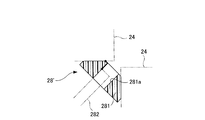
- the hexagon socket head bolt 282 is inserted into the coil support body portion 281 as in the coil support 28 'shown in FIG.
- the field winding support member of the salient pole rotor according to the present embodiment is used, even if the insulating plate on the lower surface of the field winding 24 is eliminated, as described above, the desired Insulation creepage distance can be secured.
Landscapes
- Engineering & Computer Science (AREA)
- Power Engineering (AREA)
- Insulation, Fastening Of Motor, Generator Windings (AREA)
Abstract
コイル支え(28)を、樹脂からなり、隣接する界磁巻線(24)の径方向内側面にそれぞれ直接当接する当接面(281c,281d)、及び、回転軸(21)の径方向に沿って形成された挿通孔(281a)を有するコイル支え本体部(281)と、基端部が回転子継鉄(22)に固定され先端部が径方向外側へ突出し且つコイル支え本体部(281)の挿通孔(281a)に挿通された六角穴付ボルト(282)と、回転子継鉄(22)とコイル支え本体部(281)との間に介在してコイル支え本体部(281)を界磁巻線(24)側へ押圧する皿バネ(283)とを含み、挿通孔(281a)の径方向外側に、挿通孔(281a)に比較して大径に形成されたザグリ部(281b)を有する構成とした。
Description
本発明は、突極形回転子の界磁巻線支え部材に関する。
従来、突極形回転電機において、回転子の界磁巻線の各層間の絶縁物が経年変化により縮小することにより不具合が発生することを防止するため、突極形回転電機の回転子の界磁巻線を押上装置により支えることが公知となっている(例えば、下記特許文献1,2等参照)。
このような押上装置は、界磁巻線の下面にそれぞれ高強度のフェノール板、ベークライト板、ガラスエポキシ積層板等の絶縁板を配設し、この絶縁板を介して界磁巻線を径方向外側へ押圧することにより、界磁巻線を支える構造となっている。
しかしながら、界磁巻線の下面に絶縁板を配置すると、この絶縁物が断熱材として作用し、通風冷却による冷却を妨げてコイルの発熱につながるおそれがあるという問題があった。
そこで、絶縁板を廃止し、押上装置の回転子界磁巻線に当接する部分を絶縁材により構成して、押上装置により直接界磁巻線を支えることが考えられる。
一方で、一般的にIEC60664-1などの規格によれば、回転子界磁巻線は低電圧回転機に相当する実効電圧630V以下で駆動され、その絶縁沿面距離は、材料や絶縁物の表面汚損度によっても異なるが、最小沿面距離は10mmが推奨されている。そのため回転子界磁巻線に対しての沿面距離は通常この最小沿面距離に安全率を加味した絶縁距離が確保されている。
このようなことから本発明は、回転子界磁巻線の下面の絶縁板を廃止した場合であっても、所望の絶縁沿面距離を確保しつつ回転子界磁巻線を支えることが可能な突極形回転子の界磁巻線支え部材を提供することを目的とする。
上記の課題を解決するための第1の発明に係る突極形回転子の界磁巻線支え部材は、
回転子継鉄と磁極突部と磁極頭部からなる回転子鉄心が、回転軸に備えられており、前記磁極突部の周面に界磁巻線が配置されている突極形回転子の、周方向に隣接する前記界磁巻線を径方向外側へ押圧する突極形回転子の界磁巻線支え部材であって、
絶縁材からなり、隣接する前記界磁巻線の径方向内側面にそれぞれ直接当接する当接面、及び、前記回転軸の径方向に沿って形成された挿通孔が設けられたコイル支え本体部と、
基端部が前記回転子継鉄に固定され先端部が径方向外側へ突出するとともに前記先端部が前記コイル支え本体部の挿通孔に挿通されたボルトと、
前記回転子継鉄と前記コイル支え本体部との間に介在して前記コイル支え本体部を前記界磁巻線側へ押圧する弾性体と
を備え、
前記コイル支え本体部が、前記挿通孔の前記回転軸径方向外側の部分に、前記挿通孔に比較して大径に形成されたザグリ部を有する
ことを特徴とする。
回転子継鉄と磁極突部と磁極頭部からなる回転子鉄心が、回転軸に備えられており、前記磁極突部の周面に界磁巻線が配置されている突極形回転子の、周方向に隣接する前記界磁巻線を径方向外側へ押圧する突極形回転子の界磁巻線支え部材であって、
絶縁材からなり、隣接する前記界磁巻線の径方向内側面にそれぞれ直接当接する当接面、及び、前記回転軸の径方向に沿って形成された挿通孔が設けられたコイル支え本体部と、
基端部が前記回転子継鉄に固定され先端部が径方向外側へ突出するとともに前記先端部が前記コイル支え本体部の挿通孔に挿通されたボルトと、
前記回転子継鉄と前記コイル支え本体部との間に介在して前記コイル支え本体部を前記界磁巻線側へ押圧する弾性体と
を備え、
前記コイル支え本体部が、前記挿通孔の前記回転軸径方向外側の部分に、前記挿通孔に比較して大径に形成されたザグリ部を有する
ことを特徴とする。
また、上記の課題を解決するための第2の発明に係る突極形回転子の界磁巻線支え部材は、
前記絶縁材が樹脂である
ことを特徴とする。
前記絶縁材が樹脂である
ことを特徴とする。
本発明に係る突極形回転子の界磁巻線支え部材によれば、回転子界磁巻線の下面の絶縁板を廃止した場合であっても、所望の絶縁沿面距離を確保しつつ回転子界磁巻線を支えることができる。
以下、図面を用いて本発明に係る突極形回転子の界磁巻線支え部材について説明する。
図1から図6を用いて本発明の一実施例に係る突極形回転子の絶縁板の詳細を説明する。
図1に示すように、突極形回転電機1は、図示しないフレーム等に固定された略円筒状の固定子10と、固定子10の内周側に回転自在に保持された突極形回転子20を有している。
突極形回転子20の回転軸21,回転子継鉄22及び磁極突部23は、一体的に形成されており、例えば、塊状の磁性材料から切り出されて成形されたものである。回転軸21は、突極形回転子20の回転中心となるものであって、その軸方向両端部が軸受(図示省略)により、回転可能に支持されている。回転軸21の軸方向の中央部分には、回転子継鉄22が、回転軸21の周囲を覆いつつ軸方向に延在する状態で、一体的に形成されている。回転子継鉄22の外周部のうち周方向に90°ずれた位置には、磁極突部23が一体的に形成されている。つまり、磁極突部23は、回転子継鉄22の外周部から径方向外側に向けて突出すると共に、周方向において等間隔で配置されている。
磁極突部23の周面には、絶縁板(図示省略)を介して、界磁巻線(界磁コイル)24が配置されている。界磁巻線24は、板状をなす導体と板状をなす絶縁部材を径方向に交互に積層することによって構成されている。
磁極突部23の頂面(径方向外側端面)には、磁極頭部25が複数のボルト(図示省略)により固定されている。磁極頭部25の外周面と固定子10の内周面との間には隙間(径方向に数mmの隙間)が確保されている。
なお、磁極突部23と磁極頭部25により、磁極鉄心が形成されている。また、回転子継鉄22と磁極突部23と磁極頭部25により、回転子鉄心が形成されている。
なお、磁極突部23と磁極頭部25により、磁極鉄心が形成されている。また、回転子継鉄22と磁極突部23と磁極頭部25により、回転子鉄心が形成されている。
また、界磁巻線24の頂面(径方向外側端面)と磁極頭部25の内周側面(径方向内側端面)との間には、絶縁板27が設けられている。
そして、本実施例において周方向に隣り合う二つの界磁巻線24間には、その内周面側(径方向内側端面)に直接当接して界磁巻線24を押し上げるコイル支え(界磁巻線支え部材)28が配設されている。
図2に示すように、コイル支え28は、樹脂(絶縁材)からなるコイル支え本体部281と、その先端部がコイル支え本体部281に設けられた挿通孔281a(図3参照)に挿入されるとともにその基端部が回転子継鉄22に固定された六角穴付ボルト282と、六角穴付ボルト282を挿通し回転子継鉄22とコイル支え本体部281との間に介装された皿バネ(弾性体)283とを含んで構成されている。なお、本実施例において皿バネ283は、コイル支え本体部281との間に介装されたワッシャー284と、回転子継鉄22との間に介装されたスプールリテーナ285とにより支持されている。
図3及び図4に示すように、コイル支え本体部281は、側面視概ね台形状に形成され、その脚に相当する面が、周方向に隣接する界磁巻線24の径方向内側面にそれぞれ当接する当接面281c,281dとなっている。
また、上述した挿通孔281aは、コイル支え本体部281の中心部分に回転軸21の径方向に沿って設けられている。そしてこの挿通孔281aの上底側(回転軸21の径方向に対して外側)に、挿通孔281aよりも大径に形成されたザグリ部281bが設けられている。なお、本実施例において挿通孔281aは、図4に示すように界磁巻線24等の製造上の誤差を吸収することができるよう長穴となっている。これに伴い、ザグリ部281bも長穴となっている。
このように構成される本実施例に係る突極形回転子の界磁巻線支え部材によれば、ザグリ部281bを設けたことにより、図5に示すように界磁巻線24等の製造上の誤差により六角穴付ボルト282がコイル支え本体部281の挿通孔281aの端部に当接した場合であっても、図5中に太線で示すように、界磁巻線24と六角穴付ボルト282との間の沿面距離を十分に確保することが可能となる。
すなわち、ザグリ部281bを設けずに界磁巻線24の下面の絶縁板を廃止した場合は、図6に示すコイル支え28’のように、六角穴付ボルト282がコイル支え本体部281の挿通孔281aの端部に当接すると、図6中に太線で示すように、界磁巻線24から六角穴付ボルト282までの沿面距離を十分に確保することが困難となる。これに対し、本実施例に係る突極形回転子の界磁巻線支え部材を用いれば、界磁巻線24の下面の絶縁板を廃止した場合であっても、上述した通り、所望の絶縁沿面距離を確保することができる。
1 突極形回転電機
10 固定子
20 突極形回転子
21 回転軸
22 回転子継鉄
23 磁極突部
24 界磁巻線
25 磁極頭部
25a 外周面
27 絶縁板
28,28’ コイル支え
281 コイル支え本体部
281a 挿通孔
281b ザグリ部
281c,281d 当接面
282 六角穴付ボルト
283 皿バネ
284 ワッシャー
285 スプールリテーナ
10 固定子
20 突極形回転子
21 回転軸
22 回転子継鉄
23 磁極突部
24 界磁巻線
25 磁極頭部
25a 外周面
27 絶縁板
28,28’ コイル支え
281 コイル支え本体部
281a 挿通孔
281b ザグリ部
281c,281d 当接面
282 六角穴付ボルト
283 皿バネ
284 ワッシャー
285 スプールリテーナ
Claims (2)
- 回転子継鉄と磁極突部と磁極頭部からなる回転子鉄心が、回転軸に備えられており、前記磁極突部の周面に界磁巻線が配置されている突極形回転子の、周方向に隣接する前記界磁巻線を径方向外側へ押圧する突極形回転子の界磁巻線支え部材であって、
絶縁材からなり、隣接する前記界磁巻線の径方向内側面にそれぞれ直接当接する当接面、及び、前記回転軸の径方向に沿って形成された挿通孔が設けられたコイル支え本体部と、
基端部が前記回転子継鉄に固定され先端部が径方向外側へ突出するとともに前記先端部が前記コイル支え本体部の挿通孔に挿通されたボルトと、
前記回転子継鉄と前記コイル支え本体部との間に介在して前記コイル支え本体部を前記界磁巻線側へ押圧する弾性体と
を備え、
前記コイル支え本体部が、前記挿通孔の前記回転軸径方向外側の部分に、前記挿通孔に比較して大径に形成されたザグリ部を有する
ことを特徴とする突極形回転子の界磁巻線支え部材。 - 前記絶縁材が樹脂である
ことを特徴とする請求項1記載の突極形回転子の界磁巻線支え部材。
Priority Applications (1)
| Application Number | Priority Date | Filing Date | Title |
|---|---|---|---|
| US16/492,226 US10693339B2 (en) | 2017-03-10 | 2018-03-06 | Field winding support member for salient pole rotor |
Applications Claiming Priority (2)
| Application Number | Priority Date | Filing Date | Title |
|---|---|---|---|
| JP2017-045799 | 2017-03-10 | ||
| JP2017045799A JP6497402B2 (ja) | 2017-03-10 | 2017-03-10 | 突極形回転子の界磁巻線支え部材 |
Publications (1)
| Publication Number | Publication Date |
|---|---|
| WO2018164093A1 true WO2018164093A1 (ja) | 2018-09-13 |
Family
ID=63448967
Family Applications (1)
| Application Number | Title | Priority Date | Filing Date |
|---|---|---|---|
| PCT/JP2018/008484 Ceased WO2018164093A1 (ja) | 2017-03-10 | 2018-03-06 | 突極形回転子の界磁巻線支え部材 |
Country Status (3)
| Country | Link |
|---|---|
| US (1) | US10693339B2 (ja) |
| JP (1) | JP6497402B2 (ja) |
| WO (1) | WO2018164093A1 (ja) |
Families Citing this family (2)
| Publication number | Priority date | Publication date | Assignee | Title |
|---|---|---|---|---|
| JP2024151059A (ja) * | 2023-04-11 | 2024-10-24 | 株式会社日立インダストリアルプロダクツ | 回転電機及び回転電機システム |
| CN119519293B (zh) * | 2024-10-31 | 2025-06-13 | 杭州新恒力电机制造有限公司 | 中大型同步电动机转子磁极安装定位辅助装置 |
Citations (4)
| Publication number | Priority date | Publication date | Assignee | Title |
|---|---|---|---|---|
| JPS5298902A (en) * | 1976-02-11 | 1977-08-19 | Siemens Ag | Salienttpole electric machine airrcooled salienttpole rotor |
| JPS5417005U (ja) * | 1977-07-07 | 1979-02-03 | ||
| JPH0377251U (ja) * | 1989-08-10 | 1991-08-02 | ||
| JPH07163078A (ja) * | 1993-12-06 | 1995-06-23 | Hitachi Ltd | 突極形回転機の回転子 |
Family Cites Families (4)
| Publication number | Priority date | Publication date | Assignee | Title |
|---|---|---|---|---|
| JPS61126757U (ja) | 1985-01-28 | 1986-08-08 | ||
| US4990810A (en) * | 1989-07-18 | 1991-02-05 | Westinghouse Electric Corp. | Coil carrier fixture and field coil carrier assembly |
| JP6353738B2 (ja) * | 2014-08-20 | 2018-07-04 | 株式会社日立製作所 | 回転電機 |
| JP2017085829A (ja) * | 2015-10-30 | 2017-05-18 | 株式会社日立製作所 | 回転電機 |
-
2017
- 2017-03-10 JP JP2017045799A patent/JP6497402B2/ja active Active
-
2018
- 2018-03-06 US US16/492,226 patent/US10693339B2/en active Active
- 2018-03-06 WO PCT/JP2018/008484 patent/WO2018164093A1/ja not_active Ceased
Patent Citations (4)
| Publication number | Priority date | Publication date | Assignee | Title |
|---|---|---|---|---|
| JPS5298902A (en) * | 1976-02-11 | 1977-08-19 | Siemens Ag | Salienttpole electric machine airrcooled salienttpole rotor |
| JPS5417005U (ja) * | 1977-07-07 | 1979-02-03 | ||
| JPH0377251U (ja) * | 1989-08-10 | 1991-08-02 | ||
| JPH07163078A (ja) * | 1993-12-06 | 1995-06-23 | Hitachi Ltd | 突極形回転機の回転子 |
Also Published As
| Publication number | Publication date |
|---|---|
| JP2018152937A (ja) | 2018-09-27 |
| US10693339B2 (en) | 2020-06-23 |
| JP6497402B2 (ja) | 2019-04-10 |
| US20200044508A1 (en) | 2020-02-06 |
Similar Documents
| Publication | Publication Date | Title |
|---|---|---|
| US9343934B2 (en) | Electric motor | |
| JP6688068B2 (ja) | 電気モータ | |
| JP5066062B2 (ja) | 回転電機および回転電機の製造方法 | |
| JP6484824B2 (ja) | 電動機 | |
| JP2015091146A (ja) | 集中巻回転電機のステータ、及びこれを備えた回転電機 | |
| JP6566896B2 (ja) | ステータの製造方法、および巻線装置 | |
| JP2014045634A (ja) | ロータ及びこのロータを備える回転電機 | |
| JP2009089584A (ja) | 電動機 | |
| JP6497402B2 (ja) | 突極形回転子の界磁巻線支え部材 | |
| JP2012200116A (ja) | 電動機 | |
| CN103688446B (zh) | 用于电动机的动子的环形元件 | |
| KR20090053475A (ko) | 마그네트 매입형 비엘디씨 모터 및 회전자 | |
| JP6515322B2 (ja) | 回転電機の固定子 | |
| WO2015114794A1 (ja) | アキシャルギャップ型回転電機 | |
| WO2014203849A1 (ja) | 回転電機及び回転電機の製造方法 | |
| JP6230475B2 (ja) | 突極形回転子 | |
| KR101668182B1 (ko) | 모터의 회전자 조립 방법 | |
| JP2024041219A (ja) | モータ | |
| JP2025109873A (ja) | 電気モータで使用するためのステータ | |
| KR100806112B1 (ko) | 원통형 리니어 모터의 절연구조 | |
| JP6497263B2 (ja) | 回転電機ステータ | |
| JPS626827Y2 (ja) | ||
| JP2018152936A (ja) | 突極形回転子の絶縁板 | |
| KR102297685B1 (ko) | 로터조립체 이를 포함하는 모터 | |
| JP2007104863A (ja) | 外転型コンデンサ電動機の固定子 |
Legal Events
| Date | Code | Title | Description |
|---|---|---|---|
| 121 | Ep: the epo has been informed by wipo that ep was designated in this application |
Ref document number: 18764058 Country of ref document: EP Kind code of ref document: A1 |
|
| NENP | Non-entry into the national phase |
Ref country code: DE |
|
| 122 | Ep: pct application non-entry in european phase |
Ref document number: 18764058 Country of ref document: EP Kind code of ref document: A1 |